1 autonomous quadcopter for fire detection autonomous quadcopter for fire detection henry chang,...
TRANSCRIPT
1
Autonomous Quadcopterfor Fire Detection
Henry Chang, Phyo Htut, Michael Ho, Roberto Bandeira
Abstract—Drone technology has improved over the last few decades and is on the verge of becoming ubiquitous in modern life. Ourproject aims to develop an application for drones -specifically quadcopters- that can help solve a real problem. We decided to engineeran autonomous quadcopter for early detection of wildfires by modifying an existing code base intended for radio control, addingsensors to aid in detection of fires, and designing a custom frame. We employ the use of Micro Air Vehicle Communication Protocol(MAVLink) to send the start command and to receive data such as the location of a fire.
Index Terms—Quadcopter, Autonomous, MAVLink, ArduCopter, Wildfire
F
1 INTRODUCTION
CALIFORNIA’S drought problem has led to a need forheightened monitoring of psychrometrics. The dry
weather makes the environment more susceptible to forestfires and puts residents of heavily forested areas at risk.Therefore, we wanted a solution to catch those forest fireswhile they are still developing. This project designs andimplements an autonomous quadcopter with basic obstacleavoidance which will track down a fire (or any other heatsource) and send the GPS position of the hazard onceidentified. Upon detection of the heat source, in additionto sending the GPS location, it will continue to track the firefront as it moves over time.
2 MATERIALS
2.1 Hardware
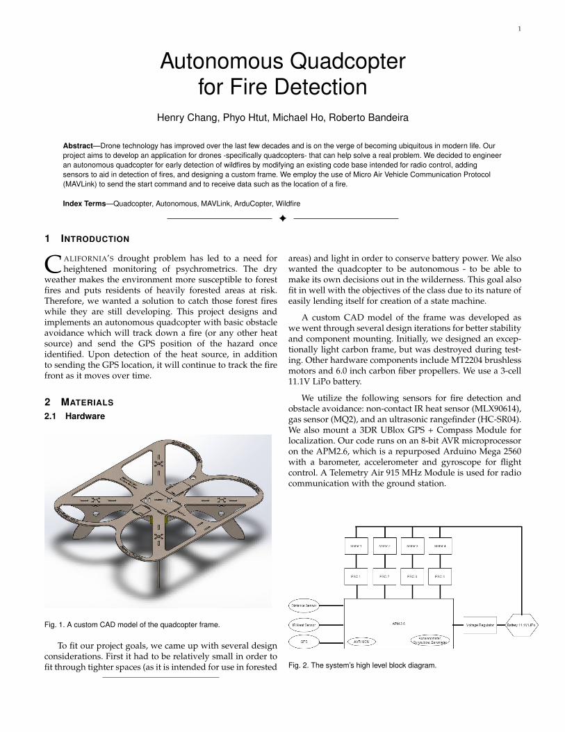
Fig. 1. A custom CAD model of the quadcopter frame.
To fit our project goals, we came up with several designconsiderations. First it had to be relatively small in order tofit through tighter spaces (as it is intended for use in forested
areas) and light in order to conserve battery power. We alsowanted the quadcopter to be autonomous - to be able tomake its own decisions out in the wilderness. This goal alsofit in well with the objectives of the class due to its nature ofeasily lending itself for creation of a state machine.
A custom CAD model of the frame was developed aswe went through several design iterations for better stabilityand component mounting. Initially, we designed an excep-tionally light carbon frame, but was destroyed during test-ing. Other hardware components include MT2204 brushlessmotors and 6.0 inch carbon fiber propellers. We use a 3-cell11.1V LiPo battery.
We utilize the following sensors for fire detection andobstacle avoidance: non-contact IR heat sensor (MLX90614),gas sensor (MQ2), and an ultrasonic rangefinder (HC-SR04).We also mount a 3DR UBlox GPS + Compass Module forlocalization. Our code runs on an 8-bit AVR microprocessoron the APM2.6, which is a repurposed Arduino Mega 2560with a barometer, accelerometer and gyroscope for flightcontrol. A Telemetry Air 915 MHz Module is used for radiocommunication with the ground station.
Fig. 2. The system’s high level block diagram.

2
2.2 Firmware
ArduPilot/APM is an open source unmanned aerial vehiclesystem that supports fixed-wing aircraft, rovers, helicopters,and multicopters. The ”Ardu” part of the name comes fromits development based off the Arduino. There are severalboards associated with ArduPilot and the specific code forcopters in ArduCopter; the latest iteration based off theArduino is the APM2.6, although since then the communityhas moved on to more powerful hardware such as thePixhawk PX4. However, we decided to build off the existingArduCopter code for APM boards due to our familiaritywith the Arduino format. We developed in the Linux en-vironment because although the code is in the Arduinostyle, the supporting firmware governing flight dynamics,stability, sensing, and communication are located in externallibraries and files.
The code is single-threaded and uses a scheduler thatperiodically polls for sensor inputs and performs simple cal-culations based off of those inputs. There is a hard deadlinefor each process to complete and if it does not completewithin the allotted time, the scheduler will move on to thenext process. There is a fixed amount of time for everythingin the scheduler and main loop to loop through once. Themain loop always has priority over the smaller processesin the scheduler and must complete before the scheduledtasks can be run. If there is not enough time to run everyprocess in the scheduler before the next invocation of themain loop, only the ones that can be completed will be run.Therefore it is important to place the most important pro-cesses at the beginning of the scheduler. The main loop doesthe following: 1) read the attitude and heading referencesystem, which consists of getting inertial information andcalculating attitude, 2) check the flight mode (TAKEOFF,FLY, FIRE, RETURN, DISARMED), 3) calculate the neededPID inputs for stability, attitude (pitch, roll, yaw), altitude,and velocity, 4) map those PID-derived values to desiredthrottle values and 5) output the desired throttle values tothe motors. Other tasks invoked in the scheduler includechecking if the quadcopter has landed, checking if it hascrashed, updating the needed average throttle output forhovering, and reading in and processing user inputs. Theonly user input needed for our final application is the”start” command, although others were implemented forsafe testing purposes. This will be discussed further below.
Fig. 3. A simple schematic of the feedback control implemented on themicrocontroller.
Fig. 4. Top-level of the hierarchical state machine, followed by the Flyand Fire States.
3 STATECHART
We use a hierarchical finite state machine to determineour quadcopter’s states and transistions between states. Wepresent a high-level diagram of the top level state machinealong with the nested state machines within two of the moreimportant states (see Figure 4). In the ”Disarmed” state, thequadcopter will not move until the user sends it the message”mode takeoff” through MAVLink. This command arms thequadcopter and sends it to the takeoff state, where it risesto a predefined takeoff height. Upon reaching that height,and making sure that it is relatively stable with minimalaltitude change, it will transition to the ”FLY” state, wherewe have given the quadcopter some initial velocity to fly ina certain direction. It will fly in that direction while scanningfor sign of a fire or an obstacle. If a fire or other heat source isdetected, the quadcopter will transition to the ”FIRE” state,where it will move along the gradient of greatest increasingintensity of infrared waves. The fire state can be triggeredby both the IR sensor and the CO2/smoke sensor. Alongwith moving along the temperature gradient, it will send analert over MAVLink with its GPS location as it locates theheat source. Once it reaches a temperature threshold, it willhold its location at the position related to that temperature

3
such that if the fire moves, the quadcopter will move withit but stay a safe distance away. When in the ”FLY” or”FIRE” states, if the battery is low, or the user requests thequadcopter to return, it will transition to the ”RETURN”state, and will land and disarm when it reaches its originallocation.
4 COMMUNICATION
We used a wireless communication protocol namedMAVLink that is designed for use on autonomous vehicles,and interfaced with our vehicle through a command lineinterface named MAVProxy. Our radio was a 915MHz radiothat would give us a rated range of about 1 mile, whichwas ample range for us to do testing. In a productionsystem, this may need to be changed to allow longer rangecommunication.MAVLink allowed custom messages to be sent, butMAVProxy did not have any built in capability to sendarbitrary messages easily. So, we modified MAVProxy’s”mode” module and ArduCopter to redefine a few statessuch that we could add in our own state definitions.
5 TESTING
5.1 Flight Control
A difficult part of the process of getting a flying quadcopterwas in verifying that it would respond correctly to itsinertial and barometric inputs. For initial testing on stabilityand altitude control, we left off the propellers and lifted upand rotated the quadcopter by hand. We were able to viewthrottle input data to the motors sent over a mini-USB cableto check that if we rotated the quadcopter along a certainaxis, the corresponding motors would have higher throttleinputs. For altitude control, we took the average throttleinput (See Figure 5). A desired height of 100 cm was set forthe ”Takeoff” state, and switched to the ”Land” state after10 seconds. The target height is changed incrementally so asnot to have a large error multiplied with the proportionalgain. At time = 8 seconds, the quadcopter was lifted uppast its target height to see if the motor output would dropto try to get the quadcopter to return to its lower targetheight. Although the direction of change was measured,it was impossible to test actual stability or altitude controlwithout letting it fly on its own with propellers.
5.2 Communication
After MAVLink modifications were implemented, we wereable to wirelessly send commands to the quadcopter fortesting and starting the vehicle, whereas we were originallyconnecting over USB, sending a command, and rushingto unplug the USB before the vehicle started flying. Wewere also able to get much richer debugging data, whichallowed us to wirelessly debug issues with our sensors andstabilization in real time.
Fig. 5. Average motor output data corresponding to altitude control. It isin the ”Takeoff” state for the first ten seconds and lands in the secondten seconds. Note that altitude error is clearly fed back to motor output.
5.3 Fire DetectionOur main sensor for fire detection is the MLX90614 IR sen-sor, and is accompanied by the MQ2 gas sensor to confirmthat the drone has detected the fire. First, we interfaced itthrough an Arduino UNO to familiarize ourselves with thedevice and to measure its range and sensitivity. Testing inthe kitchen while cooking, we were able to see a 4 Kelvinchange from about 10 feet away. Once the interfacing withArduino UNO was finished, we then ported into our micro-controller board, APM2.6 and integrated some statisticsto see if our measured temperature is significant enoughto change states. In order to detect fire, we first take 40
Fig. 6. Schematic of IR sensor to our Micro-controller board, APM2.6.
samples from the IR sensor during initialization while thequadcopter is still disarmed. We compute for the averagetemperature of the vicinity as well as standard deviation.This whole process takes about 5 seconds because we haveto let the samples spread out since we will just get oneidentical value if there were no delay in each reading. Also,to mitigate fluctuating readings from the IR sensor we say a
4
significant temperature is one that is 3 standard deviationsaway from the ambient value, the average of the initial 40samples.
Unfortunately for us, the sensor failed as the last mo-ment which put us in awkward spot before the demonstra-tion, since this was the main sensor for us locate and identifythe fire hazard.
As for gas sensor, just simply attaching the pins to thethe board does the trick and we can just read the valuesthrough the APM2.6 since the APM2.6 already had a builtin library to read from either analog or digital input. Beforeattaching the gas sensor onto the board, we first tested itby fine-tuning the sensor so it can detect fire hazards. Inour case, we tried to fine-tune the sensor by leaving nailpolish remover next to the sensor since the remover containsethanol, one of the substances detectable by the sensor.
5.4 Obstacle AvoidanceFor Obstacle avoidance, we used an ultrasonic distancesensor, HC-SR04, one specifically redesigned to have only3 pins instead of the usual model, that has 4 pins. In orderto use it properly, we mapped the voltage output values tothe actual distance measured, resulting in the affine functionmodel of the sensor that was used on the code.
We chose that sensor in particular because the ArduPilotbase code had a library implemented for it, but unfortu-nately the board we used did not support this version ofthe code, which resulted in us having to write our ownfunctions for it.
Once that code interface was done, the ObstacleAvoidance state of the state machine was written. Thescheduler calls a function that checks if there is an obstacleata distance of 60 cm or less and updates a flag. If at anypoint in time, that flag is updated to 1, the state would bechanged to Obstacle Avoidance, in which the Drone wouldrotate 90 degrees to the right, and then continue searchingfor fires.
6 CONCLUSION
In this project, we designed, modeled, and programmed anautonomous quadcopter. We custom built our own framesand modified existing code to serve our own purposes.We created a state machine of what kinds of behavior wewould like to see from our quadcopter and interfaced with itthrough the MAVLink communication protocol over radio.We gained experience integrating an embedded system withvarious sensors and struggled with connecting all the partstogether. In the end, we were able to demonstrate excellentstability, good altitude control, and velocity control. Withanother day’s worth of work, we would have been able toput together all our states and introduced more nuancedbehaviors. This was an amazing experience - one that wewill cherish and reflect back on as a pivotal point in oureducation.
7 FUTURE GOALS
To expand our project for its intended purpose, we wouldneed sensors with better range and accuracy. We would
need more sensors - right now our best sense of height isthrough the barometer, and pressure can fluctuate with timeeven when the actual height does not change. We envisiona swarm of power-efficient quadcopters with networkedcontrol and can congregate to find the fire front rather thana single point on the front.
So far we have a naive implementation of obstacleavoidance. We are inspired by MIT’s CSAIL Lab, whichhas recently made public an open source obstacle avoidancealgorithm that is relatively computationally inexpensive andcan travel at 30 MPH through wooded areas. The price tagof $1700 for all the components does make this somewhatof an investment.
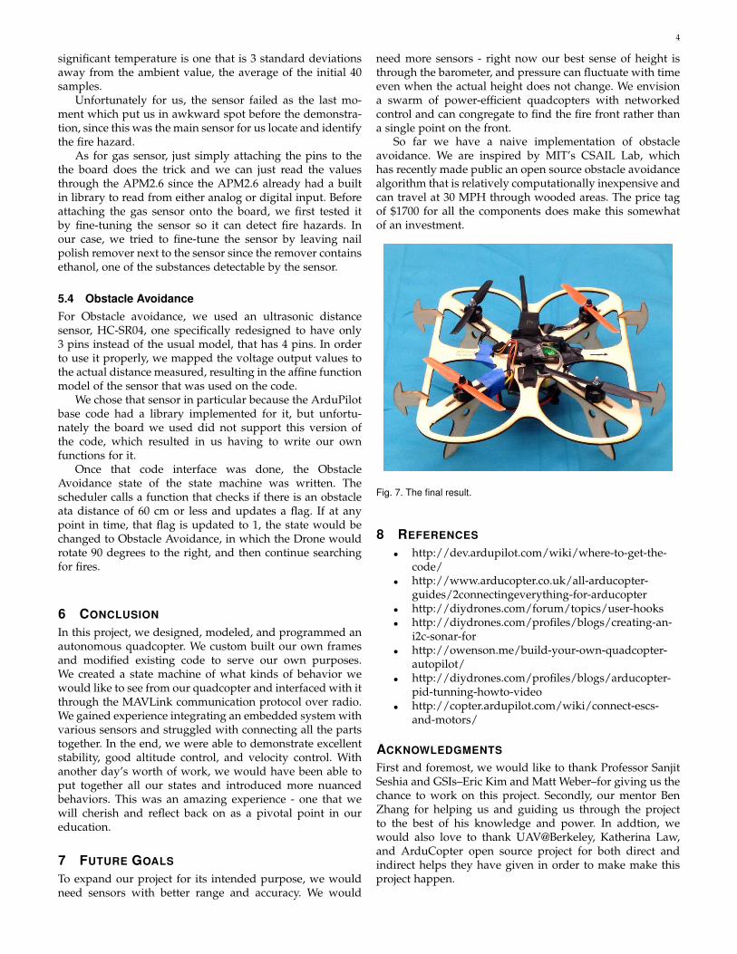
Fig. 7. The final result.
8 REFERENCES
• http://dev.ardupilot.com/wiki/where-to-get-the-code/
• http://www.arducopter.co.uk/all-arducopter-guides/2connectingeverything-for-arducopter
• http://diydrones.com/forum/topics/user-hooks• http://diydrones.com/profiles/blogs/creating-an-
i2c-sonar-for• http://owenson.me/build-your-own-quadcopter-
autopilot/• http://diydrones.com/profiles/blogs/arducopter-
pid-tunning-howto-video• http://copter.ardupilot.com/wiki/connect-escs-
and-motors/
ACKNOWLEDGMENTS
First and foremost, we would like to thank Professor SanjitSeshia and GSIs–Eric Kim and Matt Weber–for giving us thechance to work on this project. Secondly, our mentor BenZhang for helping us and guiding us through the projectto the best of his knowledge and power. In addtion, wewould also love to thank UAV@Berkeley, Katherina Law,and ArduCopter open source project for both direct andindirect helps they have given in order to make make thisproject happen.