1 a convex solution of the h -optimal controller synthesis...
TRANSCRIPT

1
A Convex Solution of the H∞-Optimal Controller Synthesis Problemfor Multi-Delay Systems
Matthew M. Peet, Member, IEEE,
Abstract
Optimal controller synthesis is a bilinear problem and hence difficult to solve in a computationally efficient manner.We are able to resolve this bilinearity for systems with delay by first convexifying the problem in infinite-dimensions -formulating the H∞ optimal state-feedback controller synthesis problem for distributed-parameter systems as a LinearOperator Inequality - a form of convex optimization with operator variables. Next, we use positive matrices to parameterizepositive “complete quadratic” operators - allowing the controller synthesis problem to be solved using SemidefiniteProgramming (SDP). We then use the solution to this SDP to calculate the feedback gains and provide effective methodsfor real-time implementation. Finally, we use several test cases to verify that the resulting controllers are optimal to severaldecimal places as measured by the minimal achievable closed-loop H∞ norm, and as compared against controllersdesigned using high-order Pade approximations.
Index Terms
Delay Systems, LMIs, Controller Synthesis.
I. INTRODUCTION
To control systems with delay, we must account for the transportation and flow of information. Although solutions toequations of the form
x(t) = A0x(t) +A1x(t− τ) +Bu(t)
appear to be functions of time, they are better understood as functions of both time and space:
x(t) = Ax(t) +A1v(t,−τ) +Bu(t)
∂tv(t, s) = ∂sv(t, s), v(t, 0) = x(t).
That is, instead of being lost, the state information, x(t), is preserved as v(t, 0), transported through a hidden process (∂tv =∂sv), moving at fixed velocity (−1m/s), through a pipe of fixed length (τm), emerges a fixed time later (t+τ ) as v(t+τ,−τ),and influences the evolution at that future time (x(t+ τ)).
The implication is that feedback controllers for systems with delay must account for both the visible part of the state, x(t),and the hidden process, v(t, s). This concept is well-established and is expressed efficiently in the use of Lyapunov-Krasovskii(LK) functions - a concept dating back to at least 1959 [1]. LK functionals V (x, v) map V : Rn × Ln2 → R+ and offer amethod for combining the states, both current (x) and hidden (v) into a single energy metric.
While the concept of a LK functional may seem obvious, this same logic has been relatively neglected in the design offeedback controllers for time-delay systems. That is, a controller should not only account for the present state, x(t) ∈ Rn, butshould also react to the hidden state v(t) ∈ L2.
The reason for the relative neglect of the hidden state lies in the development of LMI methods for control in the mid-1990s.Specifically, Ricatti equations and later LMIs were shown to be reliable and practical computational tools for designing optimaland robust controllers for finite-dimensional systems. As a result, research on stability and control of time-delay systems focusedon developing clever ways to suppress the infinite-dimensional nature of the hidden state and apply LMIs to a resulting problemin Rn - for which these tools were originally designed. For example, model transformations were used in [2]–[4], resulting ina Lyapunov function of the form V (x, v) = zTMz where
z(t) = x(t− τ) +
∫ t
t−τ(A0x(s) +A1x(s− τ)) ds.
More recently, Jenson’s inequality and free-weighting matrices have been used to parameterize ever more complex Lyapunovfunctions by projecting the distributed hidden state, v onto a finite-dimensional vector. Indeed, this approach was recentlyformalized and made infinitely scalable in [5] using a projection-based approach so that for any set of basis functions, Li(s),we may define an expanded finite-dimensional vector
zi(t) =
∫ 0
−τLi(s)v(t, s)ds.
M. Peet is with the School for the Engineering of Matter, Transport and Energy, Arizona State University, Tempe, AZ, 85298 USA. e-mail:[email protected]

2
so that the resulting Lyapunov function becomes V (x, v) = zTMz where the size of M increases with the number of basisfunctions.
Given that LMIs were developed for finite-dimensional systems, the desire to project the hidden state v ∈ L2, onto a finite-dimensional vector space is understandable. However, this approach severely limits our ability to perform controller synthesis.Specifically, these projections from P : (x, v) 7→ z are not invertible. This is problematic, since standard methods for controllersynthesis require the state transformation P to be invertible - from primal state (x, v) to dual state (x, v)). In this approach,the controllers are then designed for the dual state u(t) = Z(x, v) and then implemented on the original state using the inversetransformation u(t) = ZP−1(x, v).
In contrast to projection-based approaches, in this paper and its companion [6], we initially ignore the limitations of theLMI framework and directly formulate convex controller synthesis conditions on an infinite-dimensional space. Specifically,in [6], we formulated convex stabilizing controller synthesis conditions directly in terms of existence of a invertible statetransformation P : (x, v) 7→ (x, v) and a dual control operator Z : (x(t), v(t)) 7→ u(t). In Section III, these results areextended to provide a convex formulation of the H∞-optimal full-state feedback controller synthesis problem for a generalclass of Distributed Parameter Systems (DPS).
Having developed a convex formulation of the controller synthesis problem, the question becomes how to test feasibilityof these conditions using LMIs - a tool developed for optimization of positive matrix variables (NOT positive operators). Asdiscussed above, a natural approach is to find a way to project these operators onto a finite-dimensional state space (whereinthey become matrices) and indeed, one can view the work of [7], [8] (or in the PDE case [9]) as an attempt to do exactlythis. However, these works were unable to recover controller gains and furthermore, the feasibility conditions proposed in [6]and in Theorem 3 explicitly prohibit such an approach, as they require the positive operator to be coercive and a projectedoperator will necessarily have a non-trivial null-space.
Because projection is not an option, in this paper and in [6], we have proposed to reverse the dominant paradigm by notnarrowing the control problem to a finite-dimensional space (where we can apply LMIs), but instead to expand the LMI toolsetto explicitly allow for parametrization and optimization of operator variables. To understand how this works, let us now discardODE-based LK functions of the form V (x, v) = xTMx and instead focus on LK functions of the form
V (x, v) :=
∫ 0
−τv(s)Mv(s)ds
where the LK function is positive if M ≥ 0. Now, following the same logic presented above, we increase the complexity ofthe Lyapunov function by replacing v(s) : s 7→ Rn with z(s) : s 7→ Rq defined as
z(s) =
xZ(s)v(s)∫ 0
−τ Z(s, θ)v(θ)dθ
where Z(s) and Z(s, θ) are vectors of functions and increase the dimension of M and hence the complexity of the LKfunction — resulting in the well-known class of “complete-quadratic” functions. The advantage of this approach, then, is thatthe resulting LK function can also be represented as
V (x, v) :=
∫ 0
−τ
[xv(s)
](P[xv(·)
])(s)ds
where (P[xv
])(s) =
[Px+
∫ 0
−τ Q(θ)v(θ)dθ
Q(s)Tx+ S(s)v(s) +∫ 0
−τ R(s, θ)v(θ)dθ
]for some P , Q, S and R (Defined in Theorem 7). In this way, positive matrices represent not just positive LK functions (of thecomplete-quadratic type) but also positive operators in a standardized form - denoted P{P,Q,S,R}. This means that if we assumeour operators to have this standard form, we can enforce positivity using LMI constraints. Furthermore, linear constraints onthe matrix P and the functions Q, R and S translate to linear constraints on the elements of the positive matrix M .
The contribution of Section IV, then, is to assume all operators have the PQRS form and state conditions on the functionsP , Q, R and S such that the resulting operators satisfy the conditions of Theorem 3. Positivity is then formulated as an LMIconstraint in Section VIII.
One of the drawbacks of the proposed approach is that the resulting controllers are expressed as operators - of the formu(t) = ZP−1{P,Q,S,R}(x(t), v(t)). The solution to the LMI yields numerical values of operator Z and functions P , Q, R andS. However, in order to compute the controller gains,
u(t) = K1x(t) +K2v(t,−τ) +
∫ 0
−τK3(s)v(t, s)ds

3
we need to find P , Q, R and S such that P{P ,Q,S,R} = P−1{P,Q,S,R}. This problem is solved in Section VI (which is ageneralization of the result in [10]) by derivation of an analytic expression for P , Q, R and S in terms of P , Q, R and S.Finally, practical implementation requires an efficient numerical scheme for calculating u(t) in real-time. This issue is resolvedin Section VII.
To make the results of this paper more broadly useful, we have developed efficient implementations for: solving the LMI;calculating the feedback gains; and simulating the closed-loop response. These are available online via Code Ocean and at [11].In Section IX, the results are shown to be non-conservative to several decimal places by calculating the minimal achievableclosed-loop H∞-norm bound for several systems and comparing to results obtained using high-order Pade approximationsof the same systems. Obviously, these results presented in this paper are significantly better than any known algorithm forcontroller synthesis with provable performance metrics. Furthermore, these result can be extended in obvious ways to robustcontrol with uncertainty in system parameters or in delay.
As a final note, the reader should be aware that although the discussion here is for a single delay, the results developed arefor multiple delays - a case which requires additional mathematical formalism.
A. NotationShorthand notation used throughout this paper includes the Hilbert spaces Lm2 [X] := L2(X;Rm) of square integrable
functions from X to Rm and Wm2 [X] := W 1,2(X;Rm) = H1(X;Rm) = {x : x, x ∈ Lm2 [X]}. We use Lm2 and Wm
2 whendomains are clear from context. We also use the extensions Ln×m2 [X] := L2(X;Rn×m) and Wn×m
2 [X] := W 1,2(X;Rn×m)for matrix-valued functions. Sn ⊂ Rn×n denotes the symmetric matrices. We say an operator P : Z → Z is positive on asubset X of Hilbert space Z if 〈x,Px〉Z ≥ 0 for all x ∈ X . P is coercive on X if 〈x,Px〉Z ≥ ε ‖x‖2Z for some ε > 0 andfor all x ∈ X . Given an operator P : Z → Z and a set X ⊂ Z, we use the shorthand P(X) to denote the image of P onsubset X . In ∈ Sn denotes the identity matrix. 0n×m ∈ Rn×m is the matrix of zeros with shorthand 0n := 0n×n. We willoccasionally denote the intervals T ji := [−τi,−τj ] and T 0
i := [−τi, 0]. For a natural number, K ∈ N, we adopt the indexshorthand notation which denotes [K] = {1, · · · ,K}. The symmetric completion of a matrix is denoted ∗T .
II. THE LMI FOR H∞-OPTIMAL CONTROLLER SYNTHESIS FOR ODES
To better understand the derivation of the main result in Theorem 3, it is instructive to examine the same result in finitedimensions. This is because much of the proof of Theorem 3 is a simple generalization of the proof of the ODE synthesisLMI (Lemma 1). Indeed, it is important to state that one of the advantages of the PQRS framework (described above and inSection V) is that it simplifies the process of controlling systems with delay. Indeed, equipped with this framework and withthe theoretical justification provided in [6], almost any LMI developed for estimation and control of ODEs may be generalizedand solved for delay systems (using the highly optimized DelayTOOLS extension to SOSTOOLS [12]). To illustrate, considerthe ODE system
x(t) = Ax(t) +B1w(t) +B2u(t), x(0) = 0
y(t) = Cx(t) +D1w(t) +D2u(t).
Then the following LMI provides a necessary and sufficient condition for existence of an H∞-optimal full-state feedbackcontroller.
Lemma 1 (Full-State Feedback Controller Synthesis): Define:
G(s) =
[A+B2K B1
C +D2K D1
].
The following are equivalent.
• There exists a K such that∥∥∥G∥∥∥
H∞< γ.
• There exists a P > 0 and Z such thatPAT +AP + ZTBT2 +B2Z B1 PCT1 + ZTDT2BT1 −γI DT1
C1P +D2Z D1 −γI
< 0
Proof: The proof is a straightforward application of the KYP lemma, a duality transformation, and the Schur Complementlemma. However, since the purpose of this proof is to motivate the proof of Theorem 3, we do not rely on these classicalresults and instead prove the lemma based on first-principles. In addition, we only prove sufficiency of the non-strict inequalitysince the necessity proof of the KYP lemma does not easily generalize. First define the storage function V (x) = xTP−1x.

4
Let u(t) = ZP−1x(t). Then if x(t) is a solution of system G,
V (t) = x(t)TP−1(Ax(t) +B2ZP−1x(t) +B1w(t)) + (Ax(t) +B2ZP
−1x(t) +B1w(t))TP−1x(t)
=
[x(t)w(t)
]T [P−1(A+B2ZP
−1) + ∗T ∗TBT1 P
−1 0
] [x(t)w(t)
]=
[P−1x(t)w(t)
]T [AP +B2Z + ∗T ∗T
BT1 0
] [P−1x(t)w(t)
]Now let z(t) = P−1x(t). Then for any v, the matrix inequality implieszw
v
T AP +B2Z + ∗T ∗T ∗TBT1 −γI ∗T
C1P +D2Z D1 −γI
zwv
≤ 0
Following the proof of the Schur complement lemma, we let v = 1γ ((C1P +D2Z)z +D1w), which implieszw
v
T AP +B2Z + ∗T ∗T ∗TBT1 −γI ∗T
C1P +D2Z D1 −γI
zwv
=
[zw
]T [AP +B2Z + ∗T ∗T
BT1 −γI
] [zw
]+
1
γ
[zw
]T [(C1P +D2Z)T
DT1
] [C1P +D2Z D1
] [zw
]≤ 0
Applying this to V , we find
V (t) =
[P−1x(t)w(t)
]T [AP +B2Z + ∗T ∗T
BT1 0
] [P−1x(t)w(t)
]≤ γ ‖w‖2 − 1
γ
[zw
]T [(C1P +D2Z)T
DT1
] [C1P +D2Z D1
] [zw
]= γ ‖w‖2 − 1
γ‖(C1P +D2Z)z(t) +D1w(t)‖2
= γ ‖w‖2 − 1
γ‖C1x(t) +D2Kx(t) +D1w(t)‖2
= γ ‖w‖2 − 1
γ‖y(t)‖2 .
If w = 0, the LMI implies the system is exponentially stable, which implies limt→∞ ‖x(t)‖ = 0, which implies limt→∞ V (t) =0. Since V (0) = 0, integrating the inequality forward in time, we obtain
1
γ‖y‖2L2
≤ γ ‖w‖2L2
which completes the proof.In the following section, we replicate these steps, simply expandingzw
v
T AP +B2Z + ∗T ∗T ∗TBT1 −γI ∗T
C1P +D2Z D1 −γI
zwv
< 0
and replacing terms such as zTAPz with inner products on the appropriate function space as in 〈z,APz〉. Here the boldversion of z emphasizes this term lies in a function space and the calligraphic notation A indicates A is an operator.
III. AN CONVEX FORMULATION OF THE CONTROLLER SYNTHESIS PROBLEM FOR DISTRIBUTED PARAMETERSYSTEMS
Consider the generic distributed-parameter system
x(t) = Ax(t) + B1w(t) + B2u(t), x(0) = 0,
y(t) = Cx(t) +D1w(t) +D2u(t), (1)
where A : X → Z, B1 : Rm → Z, B2 : U → Z, C : X → Rq , D1 : Rm → Rq , and D2 : U → Rq .We begin with the following mathematical result on duality, which is a reduced version of Theorem 3 in [6].Theorem 2: Suppose P is a bounded, coercive linear operator P : X → X with P(X) = X and which is self-adjoint with
respect to the Z inner product. Then P−1: exists; is bounded; is self-adjoint; P−1 : X → X; and P−1 is coercive.

5
Using Theorem 2, we give a convex formulation of the H∞ optimal full-state feedback controller synthesis problem. Thisresult combines: a) a relatively simple extension of the Schur complement Lemma to infinite dimensions; with b) the dualsynthesis condition in [6]. We note that the ODE equivalent (Lemma 1)of this theorem is necessary and sufficient and theproof structure can be credited with, e.g. [13].
Theorem 3: Suppose there exists an ε > 0, an operator P : Z → Z which satisfies the conditions of Theorem 2, and anoperator Z : X → U such that
〈APz, z〉Z + 〈z,APz〉Z + 〈B2Zz, z〉Z + 〈z,B2Zz〉Z+ 〈z,B1w〉Z + 〈B1w, z〉Z ≤ γw
Tw − vT (CPz)− (CPz)T v
− vT (D2Zz)− (D2Zz)T v − vT (D1w)− (D1w)T v
+ γvT v − ε ‖z‖2Zfor all z ∈ X , w ∈ Rm, and v ∈ Rq . Then for any w ∈ L2, if x(t) and y(t) satisfy x(t) ∈ X and
x(t) = (A+ B2ZP−1)x(t) + B1w(t)
y(t) = (C +D2ZP−1)x(t) +D1w(t) (2)
for all t ≥ 0, then ‖y‖L2≤ γ ‖w‖L2
.Proof: By Theorem 2 P−1: exists; is bounded; is self-adjoint; P−1 : X → X; and is coercive.
For w ∈ L2, let x(t) and y(t) be a solution of
x(t) = (A+ B2ZP−1)x(t) + B1w(t)
y(t) = (C +D2ZP−1)x(t) +D1w(t)
such that x(t) ∈ X for any finite t.Define the storage function V (t) =
⟨x(t),P−1x(t)
⟩Z
. Then V (t) ≥ δ ‖x(t)‖2Z for some δ > 0. Define z(t) = P−1x(t) ∈ X .Differentiating the storage function in time, we obtain
V (t) =⟨x(t),P−1(Ax(t) + B2ZP−1x(t) + B1w(t))
⟩Z
+⟨P−1(Ax(t) + B2ZP−1x(t) + B1w(t)),x(t)
⟩Z
=⟨P−1x(t),Ax(t)
⟩Z
+⟨P−1x(t),B2ZP−1x(t)
⟩Z
+⟨P−1x(t),B1w(t)
⟩Z
+⟨Ax(t),P−1x(t)
⟩Z
+⟨B2ZP−1x(t),P−1x(t)
⟩Z
+⟨B1w(t),P−1x(t)
⟩Z
= 〈z(t),APz(t)〉Z + 〈B2Zz(t), z(t)〉Z + 〈z(t),B1w(t)〉Z + 〈APz(t), z(t)〉Z + 〈z(t),B2Zz(t)〉Z + 〈B1w(t), z(t)〉Z≤ γw(t)Tw(t)− v(t)T (CPz(t))− (CPz(t))T v(t)− v(t)T (D2Zz(t))− (D2Zz(t))T v(t)− v(t)T (D1w(t))
− (D1w(t))T v(t) + γv(t)T v(t)− ε ‖z(t)‖2Z= γw(t)Tw(t)− v(t)T
((C +D2ZP−1)x(t) +D1w(t)
)−((C +D2ZP−1)x(t) +D1w(t)
)Tv(t) + γv(t)T v(t)− ε ‖z(t)‖2Z
= γw(t)Tw(t)− v(t)T y(t)− y(t)T v(t) + γv(t)T v(t)− ε ‖z(t)‖2Zfor any v(t) ∈ Rq and all t ≥ 0. Choose v(t) = 1
γ y(t) and we get
V (t) ≤ γ ‖w(t)‖2 − 2
γ‖y(t)‖2 +
1
γ‖y(t)‖2 − ε ‖z(t)‖2Z
= γ ‖w(t)‖2 − 1
γ‖y(t)‖2 − ε ‖z(t)‖2Z .
Since P is bounded, there exists a σ > 0 such that
V (t) =⟨x(t),P−1x(t)
⟩Z
= 〈z(t),Pz(t)〉Z ≤ σ ‖z(t)‖2Z .
We conclude, therefore, thatV (t) ≤ − ε
σV (t) + γ ‖w(t)‖2 − 1
γ‖y(t)‖2 .
Therefore, since w ∈ L2, we may conclude by Gronwall-Bellman that limt→∞ V (t) = 0. Integrating this expression forwardin time, and using V (0) = V (∞) = 0, we obtain
1
γ‖y‖2L2
≤ γ ‖w‖2L2
which concludes the proof.

6
IV. THEOREM 3 APPLIED TO MULTI-DELAY SYSTEMS
Theorem 3 gives a convex formulation of the controller synthesis problem for a general class of distributed-parametersystems. In this section and the next, we apply Theorem 3 to the case of systems with multiple delays. Specifically, weconsider solutions to the system of equations given by
x(t) = A0x(t) +∑i
Aix(t− τi) +B1w(t) +B2u(t)
y(t) = C0x(t) +∑i
Cix(t− τi) +D1w(t) +D2u(t) (3)
where w(t) ∈ Rm is the disturbance input, u(t) ∈ Rp is the controlled input, y(t) ∈ Rq is the regulated output, x(t) arethe state variables and τi > 0 for i ∈ [1, · · · ,K] are the delays ordered by increasing magnitude. We assume x(s) = 0 fors ∈ [−τK , 0].
Our first step, then, is to express System (3) in the abstract form of (1). Following the mathematical formalism developedin [6], we define the inner-product space Zm,n,K := {Rm×Ln2 [−τ1, 0]×· · ·×Ln2 [−τK , 0]} and for {x, φ1, · · · , φK} ∈ Zm,n,K ,we define the following shorthand notation [
xφi
]:= {x, φ1, · · · , φK},
which allows us to simplify expression of the inner product on Zm,n,K , which we define to be⟨[yψi
],
[xφi
]⟩Zm,n,K
= τKyTx+
K∑i=1
∫ 0
−τiψi(s)
Tφi(s)ds.
When m = n, we simplify the notation using Zn,K := Zn,n,K . The state-space for System (3) is defined as
X :=
{[xφi
]∈ Zn,K : φi∈Wn
2 [−τi,0] andφi(0)=x for all i∈[K]
}.
Note that X is a subspace of Zn,K and inherits the norm of Zn,K . We furthermore extend this notation to say[xφi
](s) =
[y
f(s, i)
]if x = y and φi(s) = f(s, i) for s ∈ [−τi, 0] and i ∈ [K].
We now represent the infinitesimal generator, A : X → Zn,K , of Eqn. (3) as
A[xφi
](s) :=
[A0x+
∑Ki=1Aiφi(−τi)
φi(s)
].
Furthermore, B1 : Rm → Zn,K , B2 : Rp → Zn,K , D1 : Rm → Rq , D2 : Rp → Rq , and C : Zn,K → Rp are defined as
(B1w)(s) :=
[B1w
0
], (B2u)(s) :=
[B2u
0
],(
C[ψφi
]):=[C0ψ +
∑i Ciφi(−τi)
],
(D1w)(s) :=[D1w
], (D2u)(s) :=
[D2u
]Having defined these operators, we note that for any solution x(t) of Eqn. (3), using the above notation if we define
(x(t)) (s) =
[x1(t)x2(t)
](s) =
[x(t)
x(t+ s)
]Then x satisfies Eqn. (1) using the operator definitions given above. The converse statement is also true.
A. A Parametrization of OperatorsWe now introduce a class of operators P{P,Qi,Si,Rij} : Zm,n,K → Zm,n,K , parameterized by matrix P and matrix-valued
functions Qi ∈Wm×n2 [−τi, 0], Si ∈Wn×n
2 [−τi, 0], Rij ∈Wn×n2 [[−τi, 0]× [−τj , 0]] as(
P{P,Qi,Si,Rij}[xφi
])(s) :=
[Px+
∑Ki=1
∫ 0
−τi Qi(s)φi(s)ds
τKQi(s)Tx+τKSi(s)φi(s)+
∑Kj=1
∫ 0
−τjRij(s, θ)φj(θ) dθ.
]

7
For this class of operators, the following Lemma combines Lemmas 3 and 4 in [6] and gives conditions under whichP{P,Qi,Si,Rij} satisfies the conditions of Theorem 2.
Lemma 4: Suppose that Si ∈Wn×n2 [−τi, 0], Rij ∈Wn×n
2 [[−τi, 0]× [−τj , 0]] and Si(s) = Si(s)T , Rij(s, θ) = Rji(θ, s)
T ,P = τKQi(0)T + τKSi(0) and Qj(s) = Rij(0, s) for all i, j ∈ [K]. Further suppose P{P,Qi,Si,Rij} is coercive on Zn,K .Then P{P,Qi,Si,Rij}: is a self-adjoint bounded linear operator with respect to the inner product defined on Zn,K ; mapsP{P,Qi,Si,Rij} : X → X; and P{P,Qi,Si,Rij}(X) = X .
Starting in Section V, we will assume Qi, Si, and Rij are polynomial and give LMI conditions for positivity of operatorsof the form P{P,Qi,Si,Rij}.
B. The Controller Synthesis Problem for Systems with DelayTheorem 3 gives a convex formulation of the controller synthesis problem, where the data is the 6 operators A, B1, B2, C, D1,
and D2 and the variables are the operators P and Z . For multi-delay systems, we have defined the 6 operators and parameterizedthe decision variables P using P{P,Qi,Si,Rij}. We now likewise parameterize the decision variables Z : Zn,k → Rp usingmatrices Z0, Z1i and functions Z2i as(
Z[ψφi
]):=[Z0ψ +
∑i Z1iφi(−τi) +
∑i
∫ 0−τi
Z2i(s)φi(s)ds].
The following theorem gives convex constraints on the variables P , Qi, Si, Rij , Z0, Z1i and Z2i under which Theorem 3 issatisfied when A, B1, B2, C, D1, and D2 are as defined above.
Theorem 5: Suppose that there exist Si ∈ Wn×n2 [−τi, 0], Rij ∈ Wn×n
2 [[−τi, 0]× [−τj , 0]] and Si(s) = Si(s)T such that
Rij(s, θ) = Rji(θ, s)T , P = τKQi(0)T + τKSi(0) and Qj(s) = Rij(0, s) for all i, j ∈ [K], and matrices Z0 ∈ Rp×n,
Z1i ∈ Rp×n and Z2i ∈W p×n2 [T 0
i ] such that⟨x,P{P,Qi,Si,Rij}x
⟩Zn,K
≥ ε ‖x‖2 for all x ∈ Zn,K and
⟨vwy1y2
φi
,P{D,Ei,Si,Gij}vwy1y2
φi
⟩Zq+m+n(K+1),n,K
≤ −ε∥∥∥∥[y1φi
]∥∥∥∥2Zn,K
for all y1 ∈ Rn and
vwy1y2
φi
∈ Zq+m+n(K+1),n,K where
L0 := A0P +
K∑i=1
(τKAiQi(−τi)T +
1
2Si(0)
)+B2Z0,
L1 :=1
τKC0P +
∑i
CiQi(−τi)T +1
τKD2Z0
L2i := CiSi(−τi) +1
τKD2Z1i
L3i := τKAiSi(−τi) +B2Z1i
D =
− γτKI 1
τKD1 L1 L21 . . . L2K
∗T − γτKI BT1 0 . . . 0
∗T ∗T L0 + LT0 L31 . . . L3K
∗T ∗T ∗T −S1(−τ1) . . . 0...
......
.... . .
...∗T ∗T ∗T ∗T . . . −Sk(−τK)
Ei(s) =1
τK·
C0Qi(s) +∑j CjRji(−τj , s) +D2Z2i(s)
0
τK
(A0Qi(s) + Qi(s) +
∑Kj=1AjRji(−τj , s) +B2Z2i(s)
)0...0
Gij(s, θ) :=
∂
∂sRij(s, θ) +
∂
∂θRji(s, θ)
T , i, j ∈ [K].
Then ifu(t) = ZP−1{P,Qi,Si,Rij}
[x(t)
x(t+ s)
]

8
where (Z[xφi
])(s) := Z0x+
K∑i=1
Z1iφi(−τi) +
K∑i=1
∫ 0
−τiZ2i(s)φi(s)ds,
then for any w ∈ L2, if x(t) and y(t) satisfy Eqn. (3), ‖y‖L2≤ γ ‖w‖L2
.Proof: For any w ∈ L2, using the definitions of u(t), and A, B1, B2, C, D1, D2 and Z given above, y(t) and x(t) satisfy
Eqn. (3) if and only if y(t) and x(t) :=
[x(t)
x(t+ s)
]satisfy Eqn. (1). Therefore, ‖y‖L2
≤ γ ‖w‖L2if
〈APz, z〉Z + 〈z,APz〉Z + 〈B2Zz, z〉Z + 〈z,B2Zz〉Z + 〈z,B1w〉Z + 〈B1w, z〉Z≤ γwTw − vT (CPz)− (CPzT v − vT (D2Zz)− (D2Zz)T v − vT (D1w)− (D1w)T v + γvT v − ε ‖z‖2Z
for all z ∈ X , w ∈ Rm, and v ∈ Rq . The rest of the proof is lengthy but straightforward. We simply show that if we define
f =[z2,1(−τ1)T · · · z2,K(−τK)T
]T,
then
〈APz, z〉Z + 〈z,APz〉Z + 〈B2Zz, z〉Z + 〈z,B2Zz〉Z + 〈z,B1w〉Z + 〈B1w, z〉Z− γwTw + vT (CPz) + (CPz)T v + vT (D2Zz) + (D2Zz)T v + vT (D1w) + (D1w)T v − γvT v (4)
=
⟨vwz1f
z2i
,P{D,Ei,Si,Gij}vwz1f
z2i
⟩Zq+m+n(K+1),n,K
≤ −ε∥∥∥∥[z1z2i
]∥∥∥∥2Zn,K
= −ε ‖z‖2Zn,K .
Before we begin, for convenience and efficiency of presentation, we will denote m0 := q +m+ n(K + 1) and
h :=[vT wT zT1 fT
]T.
It may also be helpful to note that the quadratic form defined by a P{D,Ei,Fi,Gij} operator expands out as⟨[hz2i
],P{D,Ei,Fi,Gij}
[hz2i
]⟩Zm0,n,K
= τKhTDh+ τK
K∑i=1
∫ 0
−τihTEi(s)z2i(s)ds+ τK
∑i
∫ 0
−τiz2i(s)
TEi(s)Thds
+ τK∑i
∫ 0
−τiz2i(s)
TFi(s)z2i(s)ds+∑ij
∫ 0
−τi
∫ 0
−τjz2i(s)
TGij(s, θ)z2j(θ) dθds. (5)
Our task, therefore, is simply to write all the terms we find in (4) in the form of Equation (5) for an appropriate choice ofmatrix D and functions Ei, Fi, and Gij . Fortunately, the most complicated part of this operation has already been completed.Indeed, from Theorem 5 in [6], we have the first two terms can be represented as
〈APz, z〉Zn,K + 〈z,APz〉Zn,K =
⟨[hz2i
],D[hz2i
]⟩Zm0,n,K
,

9
where D := P{D1,E1i,Si,Gij} (Do not confuse this D1 with the D1 in Eqn. (1)) and
D1 :=
0 0 0 0 . . . 00 0 0 0 . . . 00 0 C0 + CT0 C1 · · · Ck0 0 CT1 −S1(−τ1) 0 0...
...... 0
. . . 00 0 CkT 0 0 −Sk(−τK)
,
C0 :=A0P+τK
K∑i=1
(AiQi(−τi)T+1
2Si(0)),
Ci := τKAiSi(−τi), i ∈ [K]
E1i(s) :=[0 0 Bi(s)
T 0 · · · 0]T, i ∈ [K]
Bi(s) := A0Qi(s) + Qi(s) +
K∑j=1
AjRji(−τj , s), i ∈ [K]
Gij(s, θ) :=∂
∂sRij(s, θ) +
∂
∂θRji(s, θ)
T , i, j ∈ [K].
Having already dealt with the most difficult terms, we now start with the easiest. Recalling that
(B1w)(s) :=
[B1w
0
], (D1w)(s) :=
[D1w
],
We have 〈z,B1w〉Z = τKzT1 B1w and hence
〈z,B1w〉Z + 〈B1w, z〉Z − γwTw + vTD1w + (D1w)T v − γvT v
= τK
vwz1
z21(−τ1)...
z2K(−τK)
T
1
τK
−γI D1 0 0 . . . 0
DT1 −γI τKBT1 0 . . . 0
0 τKB1 0 0 . . . 00 0 0 0 . . . 0...
......
.... . .
...0 0 0 0 . . . 0
︸ ︷︷ ︸
D0
vwz1
z21(−τ1)...
z2K(−τK)
=
⟨[hz2i
],P{D0,0,0,0}
[hz2i
]⟩Zm0,n,K
Next, we consider the terms
vT (CPz) + (CPz)T v
If we recall that (C[ψφi
]):=[C0ψ +
∑i Ciφi(−τi)
],
10
then we have the expansion
2vT (CPz)
= 2vT[C0(Pz1 +
K∑i=1
∫ 0
−τiQi(s)z2i(s)ds) +
∑i
Ci
(τKQi(−τi)T z1+ τKSi(−τi)z2i(−τi)+
K∑j=1
∫ 0
−τjRij(−τi, θ)z2j(θ) dθ
)]
= 2vT[(
C0P +∑i
τKCiQi(−τi)T)z1
+ τK∑i
CiSi(−τi)z2i(−τi) +
K∑i=1
∫ 0
−τi(C0Qi(s)) z2i(s)ds+
K∑i=1
∫ 0
−τi
∑j
CjRji(−τj , s)z2i(s) ds]
= 2vTτK
[( 1
τKC0P+
∑i
CiQi(−τi)T)z1+
∑i
CiSi(−τi)z2i(−τi) +1
τK
K∑i=1
∫ 0
−τi
C0Qi(s) +∑j
CjRji(−τj , s)
z2i(s)ds]
= τK
vwz1
z21(−τ1)...
z2K(−τK)
T
1
τK
0 0 C0P +∑i τKCiQi(−τi)
T τKC1S1(−τ1) . . . τKCKSK(−τK)
∗T 0 0 0 . . . 0
∗T ∗T 0 0 . . . 0
∗T ∗T ∗T 0 . . . 0...
......
.... . .
...∗T ∗T ∗T ∗T . . . 0
︸ ︷︷ ︸
D2
vwz1
z21(−τ1)...
z2K(−τK)
+ 2τK
K∑i=1
∫ 0
−τi
vwz1
z21(−τ1)...
z2K(−τK)
T
1
τK
C0Qi(s) +∑j CjRji(−τj , s)000...0
︸ ︷︷ ︸
E2i(s)
z2i(s)ds.
We therefore conclude thatvT (CPz) + (CPz)T v =
⟨[hz2i
],P{D2,E2i,0,0}
[hz2i
]⟩Zm0,n,K
.
We now examine the final set of terms which contain Z .
〈B2Zz, z〉Z + 〈z,B2Zz〉Z + vT (D2Zz) + (D2Zz)T v
If we recall that
(B2u)(s) :=
[B2u
0
], (D2u)(s) :=
[D2u
]

11
then we have the expansion
2 〈z,B2Zz〉Z + 2vT (D2Zz)
= 2τKzT1
[B2Z0z1 +
∑i
B2Z1iz2i(−τi) +∑i
∫ 0
−τiB2Z2i(s)z2i(s)ds
]+ 2vT
[D2Z0z1 +
∑i
D2Z1iz2i(−τi) +∑i
∫ 0
−τiD2Z2i(s)z2i(s)ds
]
= τK
vwz1
z21(−τ1)...
z2K(−τK)
T
0 ∗T ∗T ∗T . . . ∗T0 0 ∗T ∗T . . . ∗T
( 1τKD2Z0)T 0 B2Z0 + ZT0 B
T2 ∗T . . . ∗T
( 1τKD2Z11)T 0 (B2Z11)T 0 . . . ∗T
......
......
. . ....
( 1τKD2Z1K)T 0 (B2Z1K)T 0 . . . 0
︸ ︷︷ ︸
D3
vwz1
z21(−τ1)...
z2K(−τK)
+ 2τK
K∑i=1
∫ 0
−τi
v(t)w(t)z1(t)
z21(t,−τ1)...
z2K(t,−τK)
T
1
τK
D2Z2i(s)0
τKB2Z2i(s)0...0
︸ ︷︷ ︸
E3i(s)
z2i(s)ds.
We therefore conclude that
〈B2Zz, z〉+ 〈z,B2Zz〉+ vT (D2Zz) + (D2Zz)T v
=
⟨[hz2i
],P{D3,E3i,0,0}
[hz2i
]⟩Zm0,n,K
12
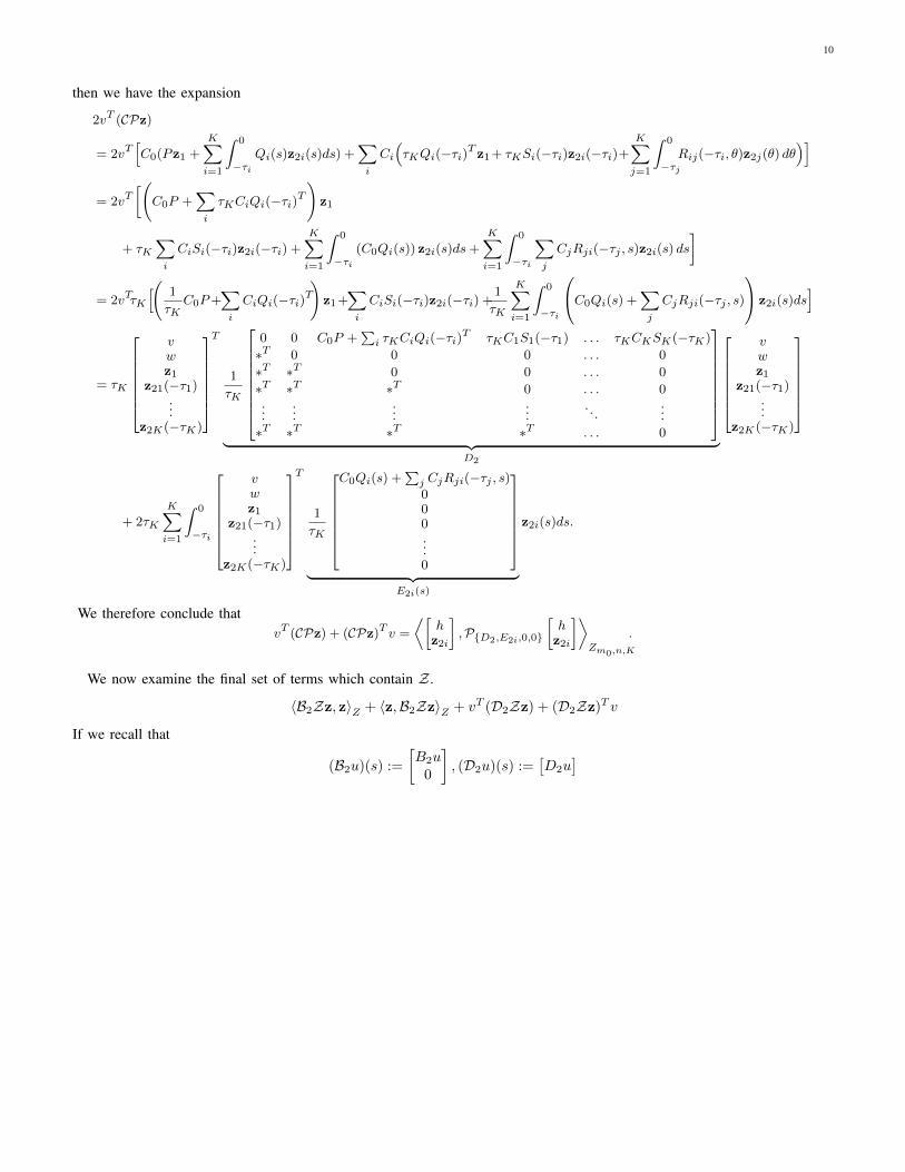
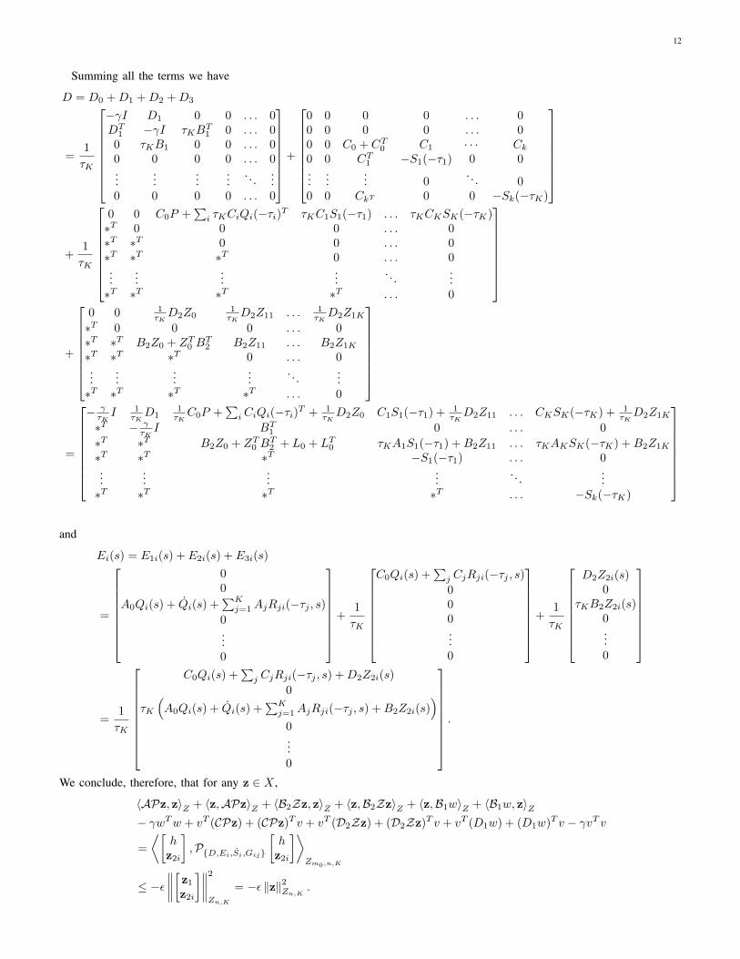
Summing all the terms we have
D = D0 +D1 +D2 +D3
=1
τK
−γI D1 0 0 . . . 0DT
1 −γI τKBT1 0 . . . 0
0 τKB1 0 0 . . . 00 0 0 0 . . . 0...
......
.... . .
...0 0 0 0 . . . 0
+
0 0 0 0 . . . 00 0 0 0 . . . 00 0 C0 + CT0 C1 · · · Ck0 0 CT1 −S1(−τ1) 0 0...
...... 0
. . . 00 0 CkT 0 0 −Sk(−τK)
+1
τK
0 0 C0P +∑i τKCiQi(−τi)T τKC1S1(−τ1) . . . τKCKSK(−τK)
∗T 0 0 0 . . . 0∗T ∗T 0 0 . . . 0∗T ∗T ∗T 0 . . . 0...
......
.... . .
...∗T ∗T ∗T ∗T . . . 0
+
0 0 1τKD2Z0
1τKD2Z11 . . . 1
τKD2Z1K
∗T 0 0 0 . . . 0∗T ∗T B2Z0 + ZT0 B
T2 B2Z11 . . . B2Z1K
∗T ∗T ∗T 0 . . . 0...
......
.... . .
...∗T ∗T ∗T ∗T . . . 0
=
− γτKI 1
τKD1
1τKC0P +
∑i CiQi(−τi)T + 1
τKD2Z0 C1S1(−τ1) + 1
τKD2Z11 . . . CKSK(−τK) + 1
τKD2Z1K
∗T − γτKI BT1 0 . . . 0
∗T ∗T B2Z0 + ZT0 BT2 + L0 + LT0 τKA1S1(−τ1) +B2Z11 . . . τKAKSK(−τK) +B2Z1K
∗T ∗T ∗T −S1(−τ1) . . . 0...
......
.... . .
...∗T ∗T ∗T ∗T . . . −Sk(−τK)
and
Ei(s) = E1i(s) + E2i(s) + E3i(s)
=
00
A0Qi(s) + Qi(s) +∑Kj=1AjRji(−τj , s)
0...0
+
1
τK
C0Qi(s) +∑j CjRji(−τj , s)000...0
+
1
τK
D2Z2i(s)0
τKB2Z2i(s)0...0
=1
τK
C0Qi(s) +∑j CjRji(−τj , s) +D2Z2i(s)
0
τK
(A0Qi(s) + Qi(s) +
∑Kj=1AjRji(−τj , s) +B2Z2i(s)
)0...0
.
We conclude, therefore, that for any z ∈ X ,
〈APz, z〉Z + 〈z,APz〉Z + 〈B2Zz, z〉Z + 〈z,B2Zz〉Z + 〈z,B1w〉Z + 〈B1w, z〉Z− γwTw + vT (CPz) + (CPz)T v + vT (D2Zz) + (D2Zz)T v + vT (D1w) + (D1w)T v − γvT v
=
⟨[hz2i
],P{D,Ei,Si,Gij}
[hz2i
]⟩Zm0,n,K
≤ −ε∥∥∥∥[z1z2i
]∥∥∥∥2Zn,K
= −ε ‖z‖2Zn,K .

13
Thus, by Lemma 4 and Theorem 3, we have that for any w ∈ L2, if x(t) and y(t) satisfy Eqn. (3), ‖y‖L2≤ γ ‖w‖L2
.
Theorem 5 provides a convex formulation of the controller synthesis problem for systems with multiple delays. However,the theorem does not provide a way to enforce the operator inequalities or reconstruct the optimal controller. In Section V wewill review how the operator inequalities can be represented using LMIs. In Sections VI and VII, we discuss how to invertoperators of the P{P,Qi,Si,Rij} class and reconstruct the controller gains in a numerically reliable manner.
V. ENFORCING OPERATOR INEQUALITIES IN THE P{P,Qi,Si,Rij} FRAMEWORK
The problem of enforcing operator positivity on Zm,n,K in the P{P,Qi,Si,Rij} framework was solved in [6] by using a two-step approach. First, we construct an operator P{P ,Q,S,R} whose positivity on Zm,nK,1 is equivalent to positivity of the originaloperator on Zm,n,K . Then, assuming that Q, R, S are polynomials, we give an LMI condition on P and the coefficients ofQ, R, S which ensures positivity of P{P ,Q,S,R} on Zm,nK,1. Because the transformation from {P,Qi, Rij , Si} to {P , Q, R, S}is linear, if Qi, Rij , Si are polynomials, the result is an LMI constraint of the coefficients of these original polynomials. Forease of implementation, these two results are combined in single Matlab function which is described in Section IX.
First, we give the following transformation. Specifically, we say that
{P , Q, S, R} := L1(P,Qi, Si, Rij) (6)if ai = τi
τK, P = P and
Q(s) :=[√a1Q1(a1s) · · · √aKQK(aKs)
]S(s) :=
S1(a1s) 0 0
0. . . 0
0 0 SK(aKs)
R(s, θ) :=√a1a1R11 (sa1, θa1) · · · √a1aKR1K (sa1, θaK)
... · · ·...√
aKa1RK1 (saK , θa1) · · · √aKaKRKK (saK , θaK)
.Then we have the following result [6].Lemma 6: Let {P , Q, S, R} := L1(P,Qi, Si, Rij). Then⟨[
xφi
],P{P,Qi,Si,Rij}
[xφi
]⟩Zm,n,K
≥ α∥∥∥∥[ xφi
]∥∥∥∥Zm,n,K
for all[xφi
]∈ Zm,n,K if and only if⟨[
x
φ
],P{P ,Q,R,S}
[x
φ
]⟩Zm,nK,1
≥ α∥∥∥∥[xφ
]∥∥∥∥Zm,nK,1
for all[x
φ
]∈ Zm,nK,1.
To enforce positivity of P{P ,Q,S,R} on Zm,nK,1 as an LMI, we use the following result [6].Theorem 7: For any functions Y1 : [−τK , 0] → Rm1×n and Y2 : [−τK , 0] × [−τK , 0] → Rm2×n, square integrable on
[−τK , 0] with g(s) ≥ 0 for s ∈ [−τK , 0], suppose that
P = M11 ·1
τK
∫ 0
−τKg(s)ds
Q(s) =1
τK
(g(s)M12Y1(s) +
∫ 0
−τKg(η)M13Y2(η, s)dη
)S(s) =
1
τKg(s)Y1(s)TM22Y1(s)
R(s, θ) = g(s)Y1(s)TM23Y2(s, θ) + g(θ)Y2(θ, s)TM32Y1(θ) +
∫ 0
−τKg(η)Y2(η, s)TM33Y2(η, θ)dη
where M11 ∈ Rm×m, M22 ∈ Rm1×m1 , M33 ∈ Rm2×m2 and
M =
M11 M12 M13
M21 M22 M23
M31 M32 M33
≥ 0.

14
Then⟨x,P{P,Q,S,R}x
⟩Zm,n,1
≥ 0 for all x ∈ Zm,n,1.For notational convenience, we use {P,Q, S,R} ∈ Ξd,m,n to denote the LMI constraints associated with Theorem 7 as
Ξd,m,n :={{P,Q,R, S} :
{P,Q,S,R}={P1,Q1,S1,R1}+{P2,Q2,S2,R2},where {P1, Q1, S1, R1} and {P2, Q2, S2, R2} satisfyThm. 7 with g = 1 and g = −s(s+ τK), respectively.
}We now have the single unified result:
Corollary 8: Suppose there exist d ∈ N, constant ε > 0, matrix P ∈ Rm×m, polynomials Qi, Si, Rij for i, j ∈ [K] suchthat
L1(P,Qi, Si, Rij) ∈ Ξd,m,nK .
Then⟨x,P{P,Qi,Si,Rij}x
⟩Zm,n,K
≥ 0 for all x ∈ Zm,n,K .A more detailed discussion of these LMI-based methods can be found in [6].
VI. AN ANALYTIC INVERSE OF P{P,Qi,Si,Rij}Having taken Qi, Rij , Si to be polynomials and having given an LMI which enforces strict positivity of the operator
P{P,Qi,Si,Rij}, we now give an analytical representation of the inverse of operators of this class. The inverse of P{P,Qi,Si,Rij}is also of the form P{P ,Qi,Si,Rij} where expressions for the matrix P and functions Qi, Rij , Si are given in the followingtheorem, which is a generalization of the result in [10] to the case of multiple delays. In this result, we first extract thecoefficients of the polynomials Qi and Rij as Qi(s) = HiZ(s) and Rij(s, θ) = Z(s)TΓijZ(θ) where Z(s) is a vector ofbases for vector-valued polynomials (typically a monomial basis). The theorem then gives an expression for the coefficientsof Qi and Rij using a similar representation. Note that the results of the theorem are still valid even if the basis functions inZ(s) are not monomials or even polynomials.
Theorem 9: Suppose that Qi(s) = HiZ(s) and Rij(s, θ) = Z(s)TΓijZ(θ) and P := P{P,Qi,Si,Rij} is a coercive operatorwhere P : X → X and P = P∗. Define
H =[H1 . . . HK
]and Γ =
Γ11 . . . Γ1K
......
ΓK,1 . . . ΓK,K
.Now let
Ki =
∫ 0
−τiZ(s)Si(s)
−1Z(s)T ds
K =
K1 0 0
0. . . 0
0 0 KK
H = P−1H
(KHTP−1H − I −KΓ
)−1Γ = −(HTH + Γ)(I +KΓ)−1
[H1 . . . HK
]= H,
Γ11 . . . Γ1K
......
ΓK,1 . . . ΓK,K
= Γ.
If we define
P =(I − HKHT
)P−1
Qi(s) = HiZ(s)Si(s)−1
Si(s) = Si(s)−1
Rij(s, θ) = Si(s)−1Z(s)T ΓijZ(θ)Sj(θ)
−1,
then for P := P{P , 1
τKQi,
1
τ2K
Si,1τK
Rij
}, we have that P = P∗, P : X → X , and PPx = PPx = x for any x ∈ Zm,n,K .
Proof: One approach to proving this theorem is to let P be as defined and show that this implies PPx = x for anyx ∈ Zm,n,K . Although this is clearly the most direct path towards establishing the theorem statement, it is not the easiestto understand, due to the intensely algebraic nature of the calculations. Thus, in order to allow the reader to understand the
15
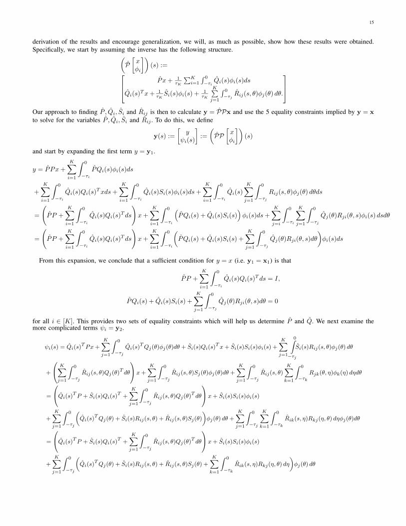
derivation of the results and encourage generalization, we will, as much as possible, show how these results were obtained.Specifically, we start by assuming the inverse has the following structure.(
P[xφi
])(s) := P x+ 1
τK
∑Ki=1
∫ 0
−τi Qi(s)φi(s)ds
Qi(s)Tx+ 1
τKSi(s)φi(s) + 1
τK
K∑j=1
∫ 0
−τj Rij(s, θ)φj(θ) dθ.
Our approach to finding P , Qi, Si and Rij is then to calculate y = PPx and use the 5 equality constraints implied by y = xto solve for the variables P , Qi, Si and Rij . To do this, we define
y(s) :=
[y
ψi(s)
]:=
(PP
[xφi
])(s)
and start by expanding the first term y = y1.
y = PPx+
K∑i=1
∫ 0
−τiPQi(s)φi(s)ds
+K∑i=1
∫ 0
−τiQi(s)Qi(s)
Txds+K∑i=1
∫ 0
−τiQi(s)Si(s)φi(s)ds+
K∑i=1
∫ 0
−τiQi(s)
K∑j=1
∫ 0
−τjRij(s, θ)φj(θ) dθds
=
(PP +
K∑i=1
∫ 0
−τiQi(s)Qi(s)
T ds
)x+
K∑i=1
∫ 0
−τi
(PQi(s) + Qi(s)Si(s)
)φi(s)ds+
K∑j=i
∫ 0
−τi
K∑j=1
∫ 0
−τjQj(θ)Rji(θ, s)φi(s) dsdθ
=
(PP +
K∑i=1
∫ 0
−τiQi(s)Qi(s)
T ds
)x+
K∑i=1
∫ 0
−τi
(PQi(s) + Qi(s)Si(s) +
K∑j=1
∫ 0
−τjQj(θ)Rji(θ, s)dθ
)φi(s)ds
From this expansion, we conclude that a sufficient condition for y = x (i.e. y1 = x1) is that
PP +
K∑i=1
∫ 0
−τiQi(s)Qi(s)
T ds = I,
PQi(s) + Qi(s)Si(s) +
K∑j=1
∫ 0
−τjQj(θ)Rji(θ, s)dθ = 0
for all i ∈ [K]. This provides two sets of equality constraints which will help us determine P and Q. We next examine themore complicated terms ψi = y2.
ψi(s) = Qi(s)TPx+
K∑j=1
∫ 0
−τjQi(s)
TQj(θ)φj(θ)dθ + Si(s)Qi(s)T x+ Si(s)Si(s)φi(s) +
K∑j=1
0∫−τj
Si(s)Rij(s, θ)φj(θ) dθ
+
K∑j=1
∫ 0
−τjRij(s, θ)Qj(θ)
T dθ
x+
K∑j=1
∫ 0
−τjRij(s, θ)Sj(θ)φj(θ)dθ +
K∑j=1
∫ 0
−τjRij(s, θ)
K∑k=1
∫ 0
−τkRjk(θ, η)φk(η) dηdθ
=
Qi(s)TP + Si(s)Qi(s)T +
K∑j=1
∫ 0
−τjRij(s, θ)Qj(θ)
T dθ
x+ Si(s)Si(s)φi(s)
+
K∑j=1
∫ 0
−τj
(Qi(s)
TQj(θ) + Si(s)Rij(s, θ) + Rij(s, θ)Sj(θ)
)φj(θ) dθ +
K∑j=1
∫ 0
−τj
K∑k=1
∫ 0
−τkRik(s, η)Rkj(η, θ) dηφj(θ)dθ
=
Qi(s)TP + Si(s)Qi(s)T +
K∑j=1
∫ 0
−τjRij(s, θ)Qj(θ)
T dθ
x+ Si(s)Si(s)φi(s)
+
K∑j=1
∫ 0
−τj
(Qi(s)
TQj(θ) + Si(s)Rij(s, θ) + Rij(s, θ)Sj(θ) +
K∑k=1
∫ 0
−τkRik(s, η)Rkj(η, θ) dη
)φj(θ) dθ

16
From this expansion, we conclude that a sufficient condition for ψi(s) = φi(s) (i.e. y2 = x2) is that
Si(s)Si(s) = I
Qi(s)TP + Si(s)Qi(s)
T +
K∑j=1
∫ 0
−τjRij(s, θ)Qj(θ)
T dθ = 0
Qi(s)TQj(θ) + Si(s)Rij(s, θ) + Rij(s, θ)Sj(θ)
+
K∑k=1
∫ 0
−τkRik(s, η)Rkj(η, θ) dη = 0.
We now have 5 constraints which P , Qi, Si and Rij must satisfy if P is to be an inverse of P:
Si(s)Si(s) = I
PP +
K∑i=1
∫ 0
−τiQi(s)Qi(s)
T ds = I
PQi(s) + Qi(s)Si(s) +
K∑j=1
∫ 0
−τjQj(θ)Rji(θ, s)dθ = 0 ∀i
Qi(s)TP + Si(s)Qi(s)
T +
K∑j=1
∫ 0
−τjRij(s, θ)Qj(θ)
T dθ = 0
Qi(s)TQj(θ) + Si(s)Rij(s, θ) + Rij(s, θ)Sj(θ)
+
K∑k=1
∫ 0
−τkRik(s, η)Rkj(η, θ) dη = 0
If all 5 constraints are satisfied, we can conclude that PPx = x. Clearly, the first constraint is satisfied if Si(s) = Si(s)−1.
We now parameterize the variables Qi and Rij as
Qi(s) = HiZ(s)Si(s), Rij(s, θ) = Si(s)TZ(s)ΓijZ(θ)Sj(θ)
and examine the second constraint, which is equivalent to
PP = I −K∑i=1
∫ 0
−τiQi(s)Z(s)T dsHT
i .
Solving this expression for P in terms of H , we obtain
P =
(I −
K∑i=1
∫ 0
−τiQi(s)Z(s)T dsHT
i
)P−1
=
(I −
K∑i=1
Hi
(∫ 0
−τiZ(s)Si(s)Z(s)T ds
)HTi
)P−1
=
(I −
K∑i=1
HiKiHTi
)P−1 =
(I − HKHT
)P−1.
We now examine the third set of constraints, indexed by i ∈ [K]:
PQi(s) + Qi(s)Si(s) +
K∑j=1
∫ 0
−τjQj(θ)Rji(θ, s)dθ
= PHiZ(s) + HiZ(s) +
K∑j=1
Hj
∫ 0
−τjZ(θ)Sj(θ)Z(θ)TΓjiZ(s)dθ
=
PHi + Hi +K∑j=1
HjKjΓji
Z(s) = 0.

17
Combining these K constraints into a single expression yields
PH + H + HKΓ = 0.
Substituting our expression for P now yields the constraint
PH + H + HKΓ
=(I − HKHT
)P−1H + H + HKΓ
= P−1H − H(KHTP−1H − I −KΓ
)= 0,
which is equivalent toH = P−1H
(KHTP−1H − I −KΓ
)−1.
Thus we have found an expression for H . Furthermore, since we have already found an expression for P in terms of H , allthat now remains is to solve for Γ. For this result, we turn to the 5th set of constraints:
Qi(s)TQj(θ) + Si(s)Rij(s, θ) + Rij(s, θ)Sj(θ) +
K∑k=1
∫ 0
−τkRik(s, η)Rkj(η, θ) dη
= Si(s)TZ(s)T HT
i HjZ(θ) + Si(s)Z(s)TΓijZ(θ) + Si(s)TZ(s)ΓijZ(θ)
+
K∑k=1
∫ 0
−τkSi(s)
TZ(s)T ΓikZ(η)Sk(η)Z(η)dηΓkjZ(θ)
= Si(s)TZ(s)T
(HTi Hj + Γij + Γij +
K∑k=1
ΓikKkΓkj
)Z(θ)
= 0 ∀i, j ∈ [K]
Combining these K2 constraints into a single expression yields
HTH + Γ + Γ + ΓKΓ = 0.
Solving this expression for Γ, we findΓ = −(HTH + Γ)(I +KΓ)−1.
We have now derived expressions for P , S, H , and Γ. However, to show that PPx = x, we must verify that the fourthconstraint is also satisfied. Namely,
Qi(s)TP + Si(s)Qi(s)
T +
K∑j=1
∫ 0
−τjRij(s, θ)Qj(θ)
T dθ
= Si(s)Z(s)T HTi P + Si(s)Z(s)THT
i +
K∑j=1
∫ 0
−τjSi(s)Z(s)T ΓijZ(θ)Sj(θ)Z(θ)T dθHT
j
= Si(s)Z(s)T
HTi P +HT
i +
K∑j=1
ΓijKjHTj
= 0
for all i ∈ [K], which is satisfied if
HTi P +HT
i +
K∑j=1
ΓijKjHTj = 0 ∀i ∈ [K].
Combining these K constraints into a single expression yields
HTP +HT + ΓKHT = 0.
To verify this is satisfied, we let L = HTP−1H and T = (I +KΓ−KL)−1. Then H = −P−1HT and thus
HTP +HT + ΓKHT
= −TTHTP−1P +HT + ΓKHT
=(−TT + I + ΓK
)HT .

18
Substituting in Γ = (TTL−Γ)(I +KΓ)−1, and observing that Γ, L and K are symmetric (for Γ, this is due to P = P∗), wehave that
− TT + I + ΓK
= I − TT + (TTL− Γ)(I +KΓ)−1K
= I − TT (I + ΓK)(I + ΓK)−1 + (TTL− Γ)K(I + ΓK)−1
= I − TT (I + ΓK)(I + ΓK)−1 + TTLK(I + ΓK)−1
− ΓK(I + ΓK)−1
= I − TT (I + ΓK + LK)(I + ΓK)−1 − ΓK(I + ΓK)−1
= I − (I + ΓK)−1 − ΓK(I + ΓK)−1
= I − (I + ΓK)(I + ΓK)−1 = I − I = 0
In a similar manner, it can be shown that PPx = x. It can be likewise shown directly that P : X → X through a lengthyseries of algebraic manipulations. However, this property is also established by Theorem 2.
VII. CONTROLLER RECONSTRUCTION AND NUMERICAL IMPLEMENTATION
In this section, we reconstruct the controller using Z and P−1 and explain how this can be implemented numerically. First,we have the following obvious result.
Lemma 10: Suppose that (Z[yψi
]):=[Z0y +
∑i Z1iψi(−τi) +
∑i
∫ 0
−τi Z2i(s)ψi(s)ds]
(7)
and (P[xφi
])(s) :=
P x+ 1τK
∑Ki=1
∫ 0
−τi Qi(s)φi(s)ds
Qi(s)Tx+ 1
τKSi(s)φi(s) + 1
τK
K∑j=1
∫ 0
−τj Rij(s, θ)φj(θ) dθ.
Then if u(t) = ZPx(t),
u(t) = K0x(t) +∑i
K1ix(t− τi) +∑i
∫ 0
−τiK2i(s)x(t+ s)ds
where
K0 = Z0P +∑j
(Z1jQj(−τj)T +
∫ 0
−τjZ2j(s)Qj(s)
T ds
)
K1i =1
τKZ1iSi(−τi)
K2i(s) =1
τK
(Z0Qi(s) + Z2i(s)Si(s) +
K∑j=1
(Z1jRji(−τj , s) +
∫ 0
θ=−τjZ2j(θ)Rji(θ, s)dθ
))Proof: Suppose that K = ZP−1 = ZP where

19
ZP[xφi
]= Z0
(P x+
1
τK
K∑i=1
∫ 0
−τiQi(s)φi(s)ds
)+∑i
Z1i
(Qi(−τi)T x+
1
τKSi(−τi)φi(−τi) +
1
τK
K∑j=1
∫ 0
−τjRij(−τi, θ)φj(θ) dθ
)
+∑i
∫ 0
−τiZ2i(s)
(Qi(s)
T x+1
τKSi(s)φi(s) +
1
τK
K∑j=1
∫ 0
θ=−τjRij(s, θ)φj(θ) dθ
)ds
= Z0P x+1
τK
K∑j=1
∫ 0
−τjZ0Qj(s)φj(s)ds+
∑i
Z1iQi(−τi)T x+1
τK
∑i
Z1iSi(−τi)φi(−τi) +1
τK
K∑j=1
∫ 0
−τj
K∑i=1
Z1iRij(−τi, s)φj(s) ds
+∑i
0∫−τi
Z2i(s)Qi(s)T xds+
1
τK
∑j
0∫−τj
Z2j(s)Sj(s)φj(s)ds+1
τK
K∑i,j=1
∫ 0
θ=−τi
∫ 0
s=−τjZ2i(θ)Rij(θ, s)φj(s) dθds
=
(Z0P +
∑i
(Z1iQi(−τi)T +
∫ 0
−τiZ2i(s)Qi(s)
T ds
))x+
1
τK
∑i
Z1iSi(−τi)φi(−τi)
+1
τK
∑j
∫ 0
−τj
(Z0Qj(s) + Z2j(s)Sj(s) +
K∑i=1
(Z1iRij(−τi, s) +
∫ 0
θ=−τiZ2i(θ)Rij(θ, s)dθ
))φj(s)ds
=
Z0P +∑j
(Z1jQj(−τj)T +
∫ 0
−τjZ2j(s)Qj(s)
T ds
)x+1
τK
∑i
Z1iSi(−τi)φi(−τi)
+1
τK
∑i
∫ 0
−τi
(Z0Qi(s) + Z2i(s)Si(s) +
K∑j=1
(Z1jRji(−τj , s) +
∫ 0
θ=−τjZ2j(θ)Rji(θ, s)dθ
))φi(s)ds
We conclude that the controller K has the form(K[xφi
]):=
[K0x+
∑i
K1iφi(−τi) +∑i
0∫−τiK2i(s)φi(s)ds
]
We conclude that given P , Qi, Si and Rij , it should be possible to compute the controller gains K0, K1i and K2i. In practice,however, if S is polynomial, then Si(s) = S(s)−1 will be a rational matrix-valued function. This implies that Qi and Rij arelikewise rational. Computing and analytically integrating such rational functions poses serious challenges. Fortunately, however,this task can be largely avoided. Specifically, if we use the formulae from Theorem 9 and substitute into the expression foru(t), we obtain the following
Corollary 11: If Z is as defined in Lemma 10 and P is as defined in Theorem 9 and u(t) = ZP[
x(t)x(t+ s)
], then
u(t) = K0x(t) +∑i
K1ix(t− τi) +∑i
∫ 0
−τiK2i(s)x(t+ s)ds
where
K0 = Z0P +∑j
(Z1jSj(−τj)−1Z(−τj)T +Oj
)HTj
K1i =1
τKZ1iSi(−τi)−1
K2i(s) =1
τK
((Z0HiZ(s) + Z2i(s)
)+
K∑j=1
(Z1jSj(−τj)−1Z(−τj)T +Oj
)ΓjiZ(s)
)Si(s)
−1
Oi =
∫ 0
−τjZ2j(s)Sj(s)
−1Z(s)T ds
The proof is straightforward.The advantage of this representation is that the matrices Oi can be numerically calculated a priori to machine precision
using trapezoidal integration without an analytic expression for S−1. Naturally, implementation still requires integration of∫ 0
−τi K2i(s)φi(s)ds in real-time. However, practical implementation of such controllers is typically based on sampling {ti} ofthe history, meaning computation of
∫ 0
−τi K2i(s)φi(s)ds can be reduced to matrix multiplication based on numerical evaluationsof S(ti)
−1. This real-time implementation can be further simplified if the state-feedback controller is combined with an H∞-optimal estimator, as described in [14].
20
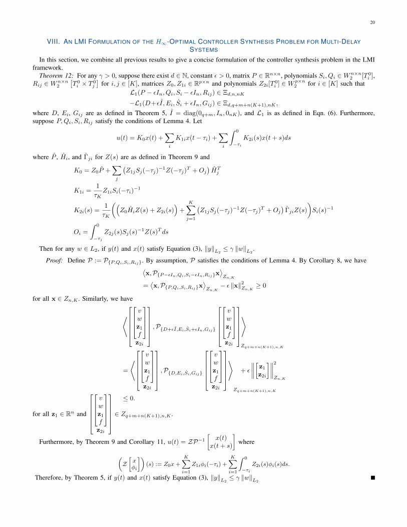
VIII. AN LMI FORMULATION OF THE H∞-OPTIMAL CONTROLLER SYNTHESIS PROBLEM FOR MULTI-DELAYSYSTEMS
In this section, we combine all previous results to give a concise formulation of the controller synthesis problem in the LMIframework.
Theorem 12: For any γ > 0, suppose there exist d ∈ N, constant ε > 0, matrix P ∈ Rn×n, polynomials Si, Qi ∈Wn×n2 [T 0
i ],Rij ∈Wn×n
2
[T 0i × T 0
j
]for i, j ∈ [K], matrices Z0, Z1i ∈ Rp×n and polynomials Z2i[T
0i ] ∈W p×n
2 for i ∈ [K] such thatL1(P − εIn, Qi, Si − εIn, Rij) ∈ Ξd,n,nK
−L1(D+εI, Ei, Si + εIn, Gij) ∈ Ξd,q+m+n(K+1),nK ,
where D, Ei, Gij are as defined in Theorem 5, I = diag(0q+m, In, 0nK), and L1 is as defined in Eqn. (6). Furthermore,suppose P,Qi, Si, Rij satisfy the conditions of Lemma 4. Let
u(t) = K0x(t) +∑i
K1ix(t− τi) +∑i
∫ 0
−τiK2i(s)x(t+ s)ds
where P , Hi, and Γji for Z(s) are as defined in Theorem 9 and
K0 = Z0P +∑j
(Z1jSj(−τj)−1Z(−τj)T +Oj
)HTj
K1i =1
τKZ1iSi(−τi)−1
K2i(s) =1
τK
((Z0HiZ(s) + Z2i(s)
)+
K∑j=1
(Z1jSj(−τj)−1Z(−τj)T +Oj
)ΓjiZ(s)
)Si(s)
−1
Oi =
∫ 0
−τjZ2j(s)Sj(s)
−1Z(s)T ds
Then for any w ∈ L2, if y(t) and x(t) satisfy Equation (3), ‖y‖L2≤ γ ‖w‖L2
.
Proof: Define P := P{P,Qi,Si,Rij}. By assumption, P satisfies the conditions of Lemma 4. By Corollary 8, we have⟨x,P{P−εIn,Qi,Si−εIn,Rij}x
⟩Zn,K
=⟨x,P{P,Qi,Si,Rij}x
⟩Zn,K
− ε ‖x‖2Zn,K ≥ 0
for all x ∈ Zn,K . Similarly, we have
⟨vwz1f
z2i
,P{D+εI,Ei,Si+εIn,Gij}
vwz1f
z2i
⟩Zq+m+n(K+1),n,K
=
⟨vwz1f
z2i
,P{D,Ei,Si,Gij}vwz1f
z2i
⟩Zq+m+n(K+1),n,K
+ ε
∥∥∥∥[z1z2i]∥∥∥∥2
Zn,K
≤ 0.
for all z1 ∈ Rn and
vwz1f
z2i
∈ Zq+m+n(K+1),n,K .
Furthermore, by Theorem 9 and Corollary 11, u(t) = ZP−1[
x(t)x(t+ s)
]where
(Z[xφi
])(s) := Z0x+
K∑i=1
Z1iφi(−τi) +
K∑i=1
∫ 0
−τiZ2i(s)φi(s)ds.
Therefore, by Theorem 5, if y(t) and x(t) satisfy Equation (3), ‖y‖L2≤ γ ‖w‖L2

21
0.2 0.4 0.6 0.8 1 1.2 1.4 1.6
Delay (s)
0
5
10
15
20
25
30
35
40
45
50H
no
rm b
ou
nd
Fig. 1. Calculated Open Loop H∞ norm bound vs. delay for Ex. A.2
IX. NUMERICAL TESTING, VALIDATION AND PRACTICAL IMPLEMENTATION
The algorithms described in this paper have been implemented in Matlab within the DelayTOOLs framework, which isbased on SOSTOOLS and the pvar framework. Several supporting functions were described in [6] and these are sufficient toenforce the conditions of Theorem 12. For all examples, the computation time is in CPU seconds on an Intel i7-5960X 3.0GHzprocessor. This time corresponds to the interior-point (IPM) iteration in SeDuMi and does not account for preprocessing,postprocessing, or for the time spent on polynomial manipulations formulating the SDP using SOSTOOLS. Such polynomialmanipulations can significantly exceed SDP computation time for small problems.
For simulation and practical use, some additional functionality has been added to facilitate calculation of controller gains andreal-time implementation. The most significant new function introduced in this paper is P_PQRS_Inverse_joint_sep_ndelay,which takes the matrix P and polynomials Qi, Si, and Rij and computes P , Hi, and Γij as described in Theorem 9. In addition,the script solver_ndelay_opt_control combines all aspects of this paper and simulates the resulting controller inclosed loop. For simulation, a fixed-step forward difference method is used, with a different set of states representing eachdelay channel. In the simulation results given below, 200 spatial discretization points are used for each delay channel.
A. Bounding the H∞ norm of a Multi-Delay SystemNaturally, the results of this paper can be used to bound the H∞ norm of a time-delay system by simply setting B2 = 0. In
this subsection, we take this approach and verify that the resulting H∞ norm bounds are accurate to several decimal places ascompared with a high-order Pade-based approximation scheme and compare favorably with existing results in the literature. Ineach case, the Pade estimate is calculated using a 10th-order Pade approximation combined with the Matlab norm command.The minimum H∞ norm bound is indicated by γmin.
a) Example A.1:
x(t) =
[−2 00 −.9
]x(t) +
[−1 0−1 −1
]x(t− τ) +
[−.51
]w(t)
y(t) =[1 0
]x(t)
d 1 2 3 Pade [15] [16]γmin .2373 .2365 .2365 .2364 .32 2
b) Example A.2: In Example A.2, we consider a well-studied example which is known to be stable for delays in the intervalτ ∈ [.100173, 1.71785].
x(t) =
[0 1−2 .1
]x(t) +
[0 01 0
]x(t− τ) +
[1 00 1
]w(t)
y(t) =[0 1
]x(t)
We use the algorithm to compute bounds for the open-loop H∞ norm of this system as the delay varies within this interval.The results are illustrated in Figure 1. Note that, as expected, the H∞ norm approaches infinity quickly as we approach thelimits of the stable region.

22
0 2 4 6 8 10 12 14 16 18 20
Times (s)
-0.5
0
0.5
1
Disturbance
States
Input
Fig. 2. Closed-loop system response to a sinc disturbance for Ex. B.3
B. Validation of H∞ optimal controller synthesisWe now apply the controller synthesis algorithm to several problems. Unfortunately, there are very few challenging example
problems available in the literature. When these examples do exist, they are often trivial in the sense that the dynamics canbe entirely eliminated by the controller - meaning only the control effort is to be minimized and the achievable norms donot change significantly with delay or other parameters. The problems listed below were found to be the most challenging asmeasured by either significant variation of the closed-loop norm with delay or the requirement for a degree of more than 1 toachieve optimal performance. In each case, the results are compared to existing results in the literature (when available) andto an H∞ optimal controller designed for the ODE obtained by using a 10th order Pade approximation of the delay terms.
c) Example B.1:
x(t) =
[0 00 1
]x(t) +
[−1 −10 −.9
]x(t− τ) +
[11
]w(t) +
[01
]u(t)
y(t) =
[1 00 0
]x(t) +
[0.1
]u(t)
γmin d = 1 d = 2 d = 3 Pade [17] [2]τ = .99 .10001 .10001 .10001 .1000 .2284 1.882τ = 2 1.438 1.353 1.332 1.339 ∞ ∞
CPU sec .478 .879 2.48 2.78 N/A N/A
d) Example B.2: This example comes from [18]. In that work, the authors set D1 = D2 = 0 and, for e.g. τ = .3, obtaineda closed loop H∞ bound of γ = .3983. Theorem 12 was able to find a closed loop controller for arbitrarily small closed-loopnorm bound (< 10−6). This is because the control effort is not included in the regulated output. We remedy this and add asecond regulated output to obtain
x(t) =
[2 10 −1
]x(t) +
[−1 0−1 1
]x(t− τ) +
[−.51
]w(t) +
[31
]u(t)
y(t) =
[1 −.50 0
]x(t) +
[01
]u(t).
γmin d = 1 d = 2 d = 3 Pade [18]τ = .3 .3953 .3953 .3953 .3953 N/A
CPU sec .655 1.248 2.72 N/A N/A
e) Example B.3: This example is a modified version of the example in [3] (B2 was modified to make the problem moredifficult and regulated outputs and disturbances were added). In that work, the authors were able to find a stabilizing controllerfor a maximum delay of τ1 = .1934 and τ2 = .2387. We are able to find a controller for any τ1 and τ2. The results here are

23
K ↓ n → 1 2 3 5 101 .438 .172 .266 1.24 17.22 .269 .643 2.932 17.1 647.23 .627 2.634 10.736 91.43 5170.25 1.294 13.12 84.77.7 1877 6528110 11.41 469.86 4439 57894 NA
TABLE ICPU SEC INDEXED BY # OF STATES (n) AND # OF DELAYS (K)
K ↓ n → 1 2 3 5 101 .9235 .9791 .9906 .9966 .99912 .8039 .9379 .9709 .9892 .99733 .7657 .9220 .9630 .9862 .99655 .7389 .9099 .9568 .9838 .995910 .7224 .9020 .9527 .9822 NA
TABLE IICLOSED-LOOP NORM BOUND INDEXED BY # OF STATES (n) AND # OF DELAYS (K)
for τ1 = 1 and τ2 = 2. The closed-loop system response is illustrated in Fig. 2.
x(t) =
[−1 20 1
]x(t) +
[.6 −.40 0
]x(t− τ1) +
[0 00 −.5
]x(t− τ2) +
[11
]w(t) +
[01
]u(t)
y(t) =
1 00 10 0
x(t) +
00.1
u(t)
γmin d = 1 d = 2 d = 3 Padeτ1 = 1, τ2 = 2 .6104 .6104 .6104 .6104
CPU sec 2.07 7.25 25.81 N/A
f) Example B.4: In this example, we rigorously examine the computational complexity of the proposed algorithm. We usea generalized n-D system with K delays, a single disturbance w(t) and a single input u(t).
x(t) =−K∑i=1
x(t− i/K)
K+ 1w(t) + 1u(t)
y(t) =
[1T
0
]x(t) +
[01
]where 1 ∈ Rn is the vector of all ones. The resulting computation time is listed in Table I. The achieved closed-loop H∞norms are listed in Table II.
As expected, these results indicate the synthesis problem is not significantly more complex that the stability test. Thecomplexity scales as a function of nK and is possible on desktop computers when nK < 50.
0 2 4 6 8 10 12 14 16 18 200
0.5
1
1.5
2
2.5
3
3.5
4
4.5
User 1 (w=1, 1s delay)
User 4 (w=4, 4s delay)
User 2 (w=2, 2s delay)
User 3 (w=3, 3s delay)
Fig. 3. A Matlab simulation of the step response of the closed-loop temperature dynamics (T2i(t)) for System (8) with 4 users (wi and τi asindicated) coupled with the controller from Theorem 12 with closed-loop gain of .36

24
C. A Scalable Design Example with Multiple State DelaysIn this subsection, we demonstrate the scalability and potential applications of the algorithm by consider a practical problem
faced in hotel management with a centralized hot-water source with multiple showering customers (a generalization of themodel proposed in [19]). Specifically, let us first consider a single user attempting to achieve a desired shower temperatureby adjusting a hot-water tap. In this case, we have an significant transport delay caused by the flow of hot water from thetap to the showerhead. In modeling the dynamics, we assume that a person will adjust the tap at a rate proportional to thedifference between current temperature and desired temperature and the overall flow rate is constant (i.e. does not depend ontemperature). Under these assumptions, we can model the linearized water temperature dynamics at the tap as
T (t) = −α (T (t− τ)− w(t))
where T is the water temperature and w(t) is the desired water temperature. When multiple users are present and the availablehot water pressure is finite, the actions of each user will affect the temperature of all other users. In a linearized model werepresent this as
Ti(t) = −αi(T (t− τi)− wi(t))−∑j 6=i
γij Tj(t)
or
Ti(t) =− αi (T (t− τi)− wi(t)) +∑j 6=i
γijαj (Tj(t− τj)− wj(t))
where we have neglected products γijγjk as it is assumed these coupling coefficients are small. Even for a single user, thesedynamics are often unstable if the delay is significant. For this reason, we introduce a centralized tracking control system tostabilize the temperature dynamics. Obviously, this controller can not sense the desired water temperatures, wi(t). The controllercan, however, sense the tap position and the actual water temperature. We account for this by including an augmented state,T1i which then represents the tap position chosen by user i. Introducing an input into the temperature dynamics yields
T1i(t) = T2i(t)− wi(t) (8)
T2i(t) = −αi (T2i(t− τi)− wi(t)) +∑j 6=i
γijαj (Tj(t− τj)− wj(t)) + ui(t)
yi(t) =
[T1i(t).1ui(t)
].
Aggregating these dynamics into the form of Equation (3), we have
A0 =
[0 I0 0
], Ai =
[0 0
0 Ai
]Ai(:, i) = αi
[γi,1 . . . γi,i−1 −1 γi,i−1 . . . γi,K
]TB1 =
[−I
−Γ + diag(α1 . . . αK)
]Γij = αjγij =
[q1 . . . qK
], B2 =
[0I
]C0 =
[I 00 0
], C1 =
[0 00 0
], D1 =
[00
], D2 =
[0.1I
]Optimal Control of Showering Users
For numerical implementation with nu users, we have a system with 2nu states, nu delays, 2nu regulated outputs and nucontrol inputs. The implementation of this example is included in the accompanying code, wherein we set αi = 1, γij = 1/nand τi = i. The resulting open-loop dynamics are unstable. For nu = 4, we obtain a closed-loop H∞ norm bound of γ = .38.For wi(t) = i, the resulting closed-loop dynamics are illustrated in Figure 3 wherein convergence to the desired showertemperature is observed for all users.
X. CONCLUSION
In this paper, we have shown how the problem of optimal control of systems with multiple delays can be reformulated as aconvex optimization problem with operator variables. We have proposed a parametrization of positive operators using positivematrices and verified the resulting LMIs are accurate to several decimal places when measured by the minimal achievableclosed-loop H∞ norm bound. We have developed an analytic formula for the inverse of the proposed parameterized class ofpositive operators. Finally, we have demonstrated effective methods for real-time computation of the control inputs. Finally,we have implemented the proposed algorithms and gains and simulated the results on a realistic model with 8 states and 4delays.
25
ACKNOWLEDGMENT
This work was supported by the National Science Foundation under grants No. 1301660, 1538374 and 1739990.
REFERENCES
[1] N. N. Krasovskii, Stability of Motion. Stanford University Press, 1963.[2] X. Li and C. De Souza, “Criteria for robust stability and stabilization of uncertain linear systems with state delay,” Automatica, vol. 33, no. 9, pp.
1657–1662, 1997.[3] Y. Cao, Y. Sun, and C. Cheng, “Delay-dependent robust stabilization of uncertain systems with multiple state delays,” IEEE Transactions on Automatic
Control, vol. 43, no. 11, pp. 1608–1612, 1998.[4] P. Park, “A delay-dependent stability criterion for systems with uncertain time-invariant delays,” IEEE Transactions on Automatic control, vol. 44, no. 4,
pp. 876–877, 1999.[5] A. Seuret and F. Gouaisbaut, “Complete quadratic lyapunov functionals using bessel-legendre inequality,” in Proceedings of the European Control
Conference, 2014, pp. 448–453.[6] M. Peet, “SOS methods for multi-delay systems: A dual form of Lyapunov-Krasovskii functional,” IEEE Transactions on Automatic Control, May 2019.[7] N. Krasovskii, “On the analytic construction of an optimal control in a system with time lags,” Journal of Applied Mathematics and Mechanics, vol. 26,
no. 1, pp. 50–67, 1962.[8] D. Ross and I. Flugge-Lotz, “An optimal control problem for systems with differential-difference equation dynamics,” SIAM Journal on Control, vol. 7,
no. 4, pp. 609–623, 1969.[9] I. Lasiecka, “Control of systems governed by partial differential equations: A historical perspective,” in Proceedings of the IEEE Conference on Decision
and Control, 1995, pp. 2792–2797.[10] G. Miao, M. Peet, and K. Gu, “Inversion of separable kernel operators in coupled differential-functional equations and application to controller synthesis,”
in Proceedings of the IFAC World Congress, 2017.[11] M. Peet, “Professional web site for Matthew M. Peet,”
http://control.asu.edu.[12] S. Prajna, A. Papachristodoulou, and P. A. Parrilo, “Introducing SOSTOOLS: a general purpose sum of squares programming solver,” Proceedings of
the IEEE Conference on Decision and Control, 2002.[13] J. Bernussou, P. Peres, and J. C. Geromel, “A linear programming oriented procedure for quadratic stabilization of uncertain systems,” Systems and
Control Letters, vol. 13, no. 1, pp. 65–72, 1989.[14] M. Peet and K. Gu, “Synthesis of full-state observers for time-delay systems using SOS,” in Proceedings of Mathematical Theory of Networks and
Systems, 2018.[15] E. Fridman and U. Shaked, “New bounded real lemma representations for time-delay systems and their applications,” IEEE Transactions on Automatic
control, vol. 46, no. 12, pp. 1973–1979, 2001.[16] U. Shaked, I. Yaesh, and C. de Souza, “Bounded real criteria for linear time-delay systems,” IEEE Transactions on Automatic Control, vol. 43, no. 7,
pp. 1016–1022, 1998.[17] E. Fridman and U. Shaked, “Delay-dependent stability and H∞ control: constant and time-varying delays,” International journal of control, vol. 76,
no. 1, pp. 48–60, 2003.[18] ——, “H∞-state-feedback control of linear systems with small state delay,” Systems & control letters, vol. 33, no. 3, pp. 141–150, 1998.[19] M. M. Peet, “Stability and control of functional differential equations,” Ph.D. dissertation, Stanford University, 2006.
PLACEPHOTOHERE
Matthew M. Peet received the B.S. degree in physics and in aerospace engineering from the University of Texas, Austin,TX, USA, in 1999 and the M.S. and Ph.D. degrees in aeronautics and astronautics from Stanford University, Stanford, CA, in2001 and 2006, respectively. He was a Postdoctoral Fellow at INRIA, Paris, France from 2006 to 2008. He was an AssistantProfessor of Aerospace Engineering at the Illinois Institute of Technology, Chicago, IL, USA, from 2008 to 2012. Currently,he is an Associate Professor of Aerospace Engineering at Arizona State University, Tempe, AZ, USA. Dr. Peet received aNational Science Foundation CAREER award in 2011.