1 © 2003, cisco systems, inc. all rights reserved. ccnp 3 v4 module 6 implementing redundancy in...
TRANSCRIPT

1© 2003, Cisco Systems, Inc. All rights reserved.
CCNP 3 v4 Module 6 Implementing Redundancy in
the Routing Layer

222© 2003, Cisco Systems, Inc. All rights reserved.
Objectives
• Configuring and optimizing Layer 3 redundancy with HSRP
• Configuring Layer 3 redundancy with VRRP and GLBP
• Implementing hardware and software redundancy with modular switches
• Describing high availability in multilayer switching

333© 2003, Cisco Systems, Inc. All rights reserved.
Overview
• A network with High Availability (HA) provides alternate means by which all infrastructure paths and key servers can be accessed at all times.
• Hot Standby Router Protocol (HSRP), Virtual Router Redundancy Protocol (VRRP) and Gateway Load Balancing Protocol (GLBP) create immediate link failover for LAN clients.
• High Availability is also accomplished by implementing redundant links and hardware, such as supervisor engines, route modules and power supplies.
444© 2003, Cisco Systems, Inc. All rights reserved.
The Router Redundancy Process
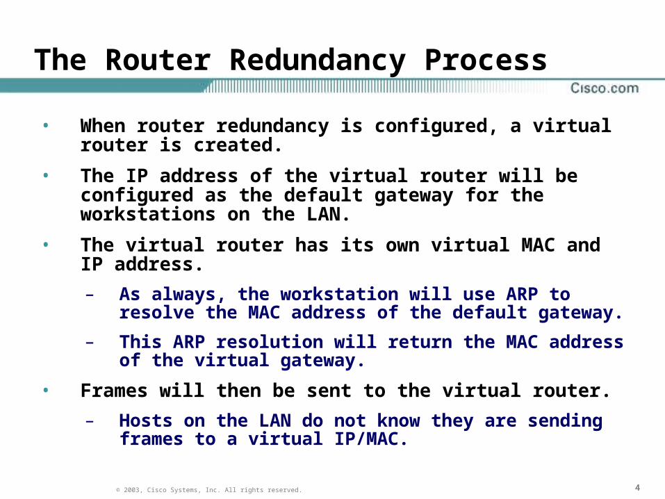
• When router redundancy is configured, a virtual router is created.
• The IP address of the virtual router will be configured as the default gateway for the workstations on the LAN.
• The virtual router has its own virtual MAC and IP address.
– As always, the workstation will use ARP to resolve the MAC address of the default gateway.
– This ARP resolution will return the MAC address of the virtual gateway.
• Frames will then be sent to the virtual router.
– Hosts on the LAN do not know they are sending frames to a virtual IP/MAC.
555© 2003, Cisco Systems, Inc. All rights reserved.
Virtual Routers
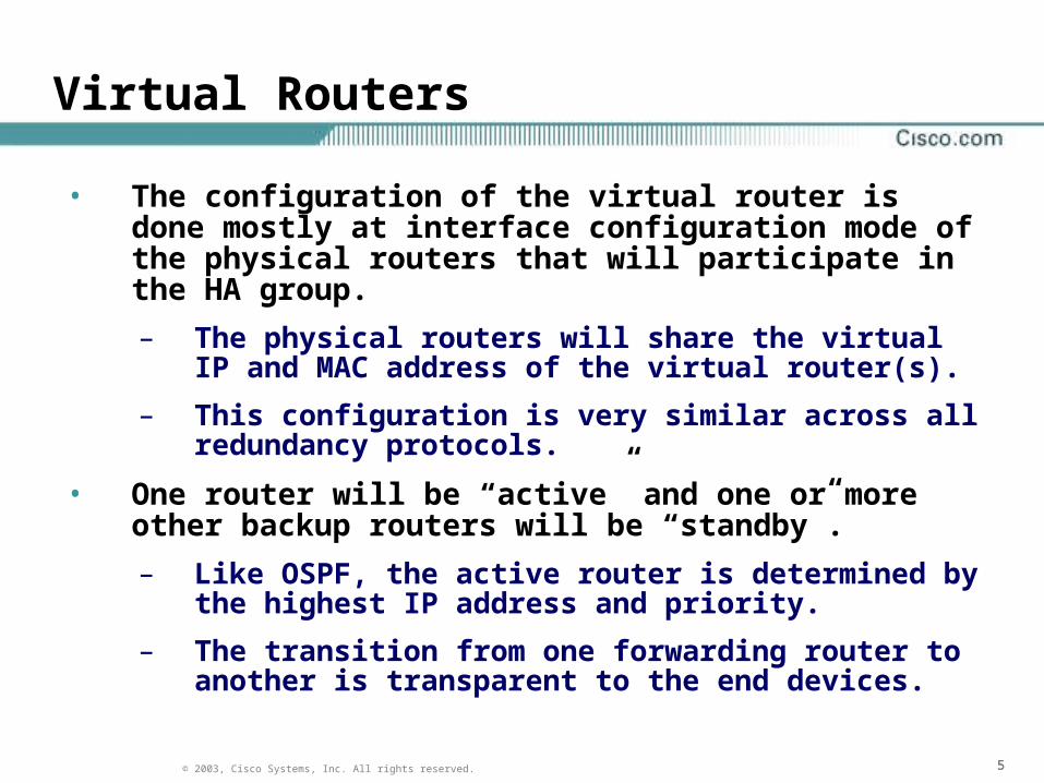
• The configuration of the virtual router is done mostly at interface configuration mode of the physical routers that will participate in the HA group.
– The physical routers will share the virtual IP and MAC address of the virtual router(s).
– This configuration is very similar across all redundancy protocols.
• One router will be “active” and one or more other backup routers will be “standby”.
– Like OSPF, the active router is determined by the highest IP address and priority.
– The transition from one forwarding router to another is transparent to the end devices.
666© 2003, Cisco Systems, Inc. All rights reserved.
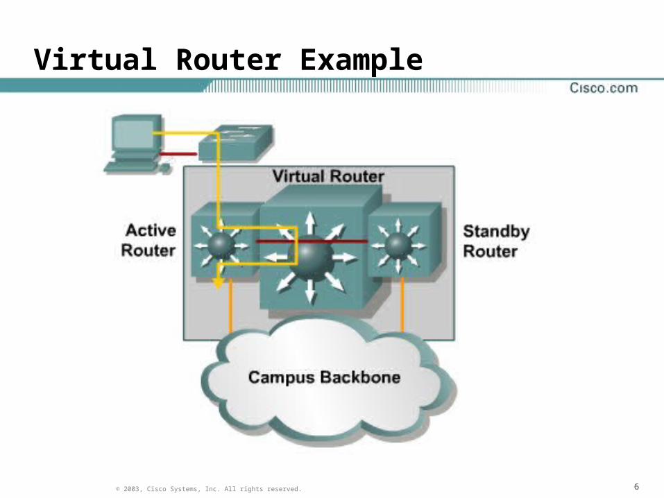
Virtual Router Example

777© 2003, Cisco Systems, Inc. All rights reserved.
Hot Standby Router Protocol (HSRP)
• HSRP defines a standby group of routers, with one router as the active router.
– HSRP consists of a virtual MAC and IP address that are shared between two or more routers that belong to the same HSRP standby group.

888© 2003, Cisco Systems, Inc. All rights reserved.
ARP Resolution with HSRP
• The IP address and corresponding MAC address of the virtual router is maintained in the ARP table of each router in an HSRP standby group.
• The MAC address of the HSRP virtual router is 0000.0c07.acxx, where xx is the HSRP group identifier.
– Here are a few examples:
– Group 1 = 0000.0c07.ac01
– Group 16 = 0000.0c07.ac10
– Group 47 = 0000.0c07.ac2f

999© 2003, Cisco Systems, Inc. All rights reserved.
HSRP Example
Note the priority ofboth routers

101010© 2003, Cisco Systems, Inc. All rights reserved.
HSRP Terminology

111111© 2003, Cisco Systems, Inc. All rights reserved.
HSRP Active and Standby Routers
• Within an HSRP standby group, one router is elected to be the active router. – The active router physically forwards packets sent
to the virtual router.
– The active router also replies with the virtual router MAC address.
• The function of the HSRP standby router is to monitor the active router and begin forwarding packets if the active router fails.– This is done by way of hello messages
121212© 2003, Cisco Systems, Inc. All rights reserved.
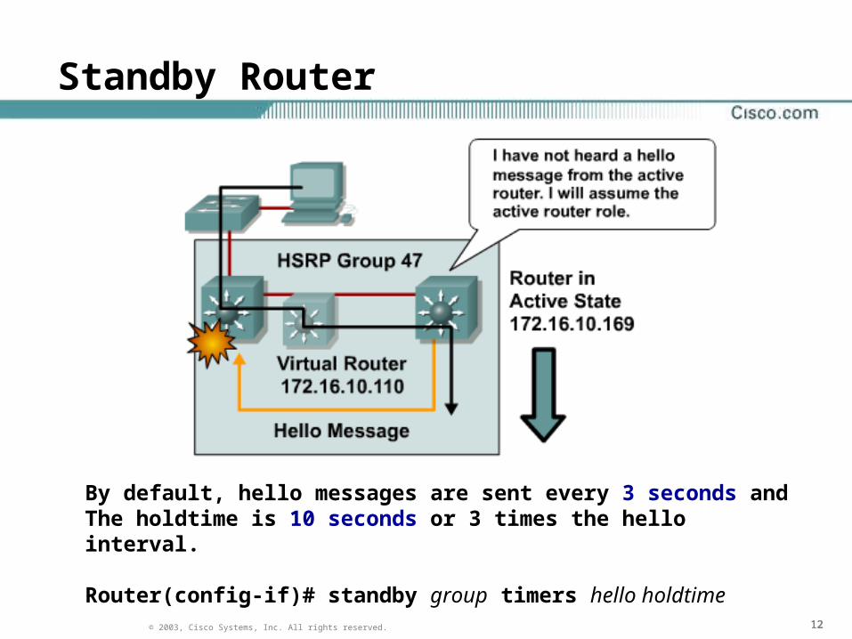
Standby Router
By default, hello messages are sent every 3 seconds andThe holdtime is 10 seconds or 3 times the hello interval.
Router(config-if)# standby group timers hello holdtime

131313© 2003, Cisco Systems, Inc. All rights reserved.
HSRP States
• A router in an HSRP standby group can be in one of the following states: initial, listen, speak, standby, or active. 1. Initial: This is the starting state and indicates that HSRP is not
running.
2. Listen: In the listen state, the router knows the IP address of the virtual router, but is neither the active router nor the standby router.
3. Speak: In the speak state, the router sends periodic hello messages and is actively participating in the election of the active router or standby router.
• The router will remain in the speak state unless it becomes an active or standby router.
4. Standby: In the standby state, because the router is a candidate to become the next active router and will listen for hellos from the active router.
• There is only one standby router for the HSRP group.
5. Active: In the active state, the router is currently forwarding packets that are sent to the virtual MAC address of the group.

141414© 2003, Cisco Systems, Inc. All rights reserved.
HSRP Configuration Commands

151515© 2003, Cisco Systems, Inc. All rights reserved.
HSRP Group Configuration
Router(config)#int fa0/0Router(config-if)#ip addr 192.168.1.3 255.255.255.0Router(config-if)#standby 1 ip 192.168.1.1Router(config-if)#standby 1 priority 200Router(config-if)#standby 1 timers 3 10Router(config-if)#standby 1 preempt ? delay Wait before preempting <cr>Router(config-if)#standby 1 preemptRouter(config-if)#standby 1 authentication standbykey% Maximum authentication string length is 8Router(config-if)#standby 1 authentication secretky
Switch(config)#int vlan 10Switch(config-if)#ip addr 192.168.10.3 255.255.255.0Switch(config-if)#standby 10 ip 192.168.10.1Switch(config-if)#standby 10 priority 200
3550:
161616© 2003, Cisco Systems, Inc. All rights reserved.
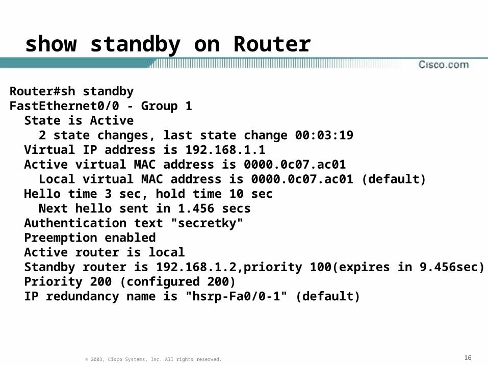
show standby on Router
Router#sh standbyFastEthernet0/0 - Group 1 State is Active 2 state changes, last state change 00:03:19 Virtual IP address is 192.168.1.1 Active virtual MAC address is 0000.0c07.ac01 Local virtual MAC address is 0000.0c07.ac01 (default) Hello time 3 sec, hold time 10 sec Next hello sent in 1.456 secs Authentication text "secretky" Preemption enabled Active router is local Standby router is 192.168.1.2,priority 100(expires in 9.456sec) Priority 200 (configured 200) IP redundancy name is "hsrp-Fa0/0-1" (default)
171717© 2003, Cisco Systems, Inc. All rights reserved.
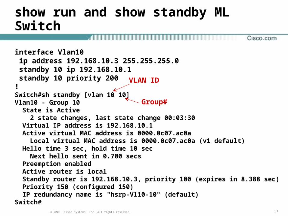
show run and show standby ML Switch
interface Vlan10 ip address 192.168.10.3 255.255.255.0 standby 10 ip 192.168.10.1 standby 10 priority 200!Switch#sh standby [vlan 10 10]Vlan10 - Group 10 State is Active 2 state changes, last state change 00:03:30 Virtual IP address is 192.168.10.1 Active virtual MAC address is 0000.0c07.ac0a Local virtual MAC address is 0000.0c07.ac0a (v1 default) Hello time 3 sec, hold time 10 sec Next hello sent in 0.700 secs Preemption enabled Active router is local Standby router is 192.168.10.3, priority 100 (expires in 8.388 sec) Priority 150 (configured 150) IP redundancy name is "hsrp-Vl10-10" (default)Switch#
VLAN ID
Group#

181818© 2003, Cisco Systems, Inc. All rights reserved.
show standby [brief]

191919© 2003, Cisco Systems, Inc. All rights reserved.
HSRP Load Sharing
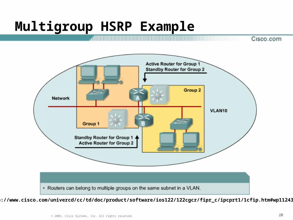
• To facilitate load sharing, a single router may be a member of multiple HSRP standby groups on a single segment. – This allows for additional redundancy and load
balancing among VLANs
– While a router is actively forwarding traffic for one HSRP group, the router can be in standby or listen state for another group.
• There can be up to 255 standby groups on any LAN.
• For each standby group, an IP address and a single well-known MAC address with a unique group identifier is allocated to the group.
202020© 2003, Cisco Systems, Inc. All rights reserved.
Multigroup HSRP Example
http://www.cisco.com/univercd/cc/td/doc/product/software/ios122/122cgcr/fipr_c/ipcprt1/1cfip.htm#wp1124304
212121© 2003, Cisco Systems, Inc. All rights reserved.
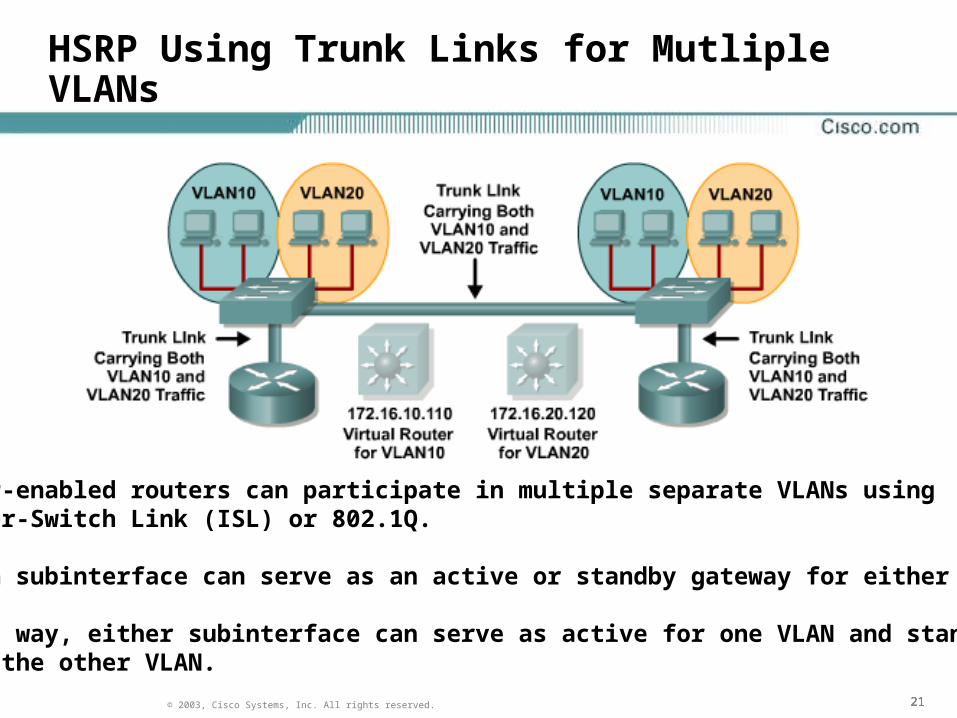
HSRP Using Trunk Links for Mutliple VLANs
HSRP-enabled routers can participate in multiple separate VLANs usingInter-Switch Link (ISL) or 802.1Q.
Each subinterface can serve as an active or standby gateway for either VLAN.
This way, either subinterface can serve as active for one VLAN and standbyfor the other VLAN.

222222© 2003, Cisco Systems, Inc. All rights reserved.
Multiple HSRP Groups and Multiple VLANs

232323© 2003, Cisco Systems, Inc. All rights reserved.
Optimizing HSRP
• HSRP Preempt
• Hello Message Timer Adjustment
• HSRP Interface Tracking

242424© 2003, Cisco Systems, Inc. All rights reserved.
HSRP Preempt
• In the event of an active router failure, a standby router will assume the role of active router.
• By default, the new active router will retain its role as active when the former active router comes back online, even if it has a higher priority than the current active router.
• In order for the former active router to regain its role as active we must configure the ‘preempt’ option.
Router(config-if)# standby 10 preempt

252525© 2003, Cisco Systems, Inc. All rights reserved.
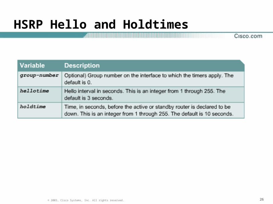
Hello Message Timer Adjustment
• HSRP interfaces send hello messages to communicate with other HSRP interfaces.
– Hello messages are used to determine which router will active and which will be standby.
– Hello messages are also used to determine if an active router has gone down.
• The hello message contains the priority of the router as well as hellotime and holdtime parameter values.
Switch(config-if)#standbygroup-number timershellotime holdtime
• The holdtime value should be at least three times the value of the hellotime.
http://www.cisco.com/univercd/cc/td/doc/product/software/ios122/122cgcr/fipr_c/ipcprt1/1cfip.htm#wp1001531
262626© 2003, Cisco Systems, Inc. All rights reserved.
HSRP Hello and Holdtimes

272727© 2003, Cisco Systems, Inc. All rights reserved.
HSRP Interface Tracking

282828© 2003, Cisco Systems, Inc. All rights reserved.
HSRP Interface Tracking
• In some situations, the status of an interface directly affects which router needs to become the active router.
• If an interface an HSRP router uses to reach some resource goes down, the HSRP router can decrease its priority to a value lower than that of the current standby router.
– This allows the standby router to become active.

292929© 2003, Cisco Systems, Inc. All rights reserved.
HSRP Interface Tracking
Router(config-if)# standby 1 track serial 0/0 50

303030© 2003, Cisco Systems, Inc. All rights reserved.
HSRP Tracking Example
http://www.cisco.com/univercd/cc/td/doc/product/software/ios122/122newft/122t/122t15/fthsrptk.htm

313131© 2003, Cisco Systems, Inc. All rights reserved.
Tuning HSRP Operations
• The HSRP hello and holdtime can be set to millisecond values so that HSRP failover occurs in less than 1 second. For example:
Switch(config-if)#standby 1 timers msec 200 msec 750
• Preempt delay time should also be set to allow the HSRP device time to reconnect with the rest of the network, i.e.. relearn the routing table or spanning-tree topology before it becomes the active router again.
standby 1 preempt delay minimum 180

323232© 2003, Cisco Systems, Inc. All rights reserved.
HSRP Debug Commands
333333© 2003, Cisco Systems, Inc. All rights reserved.
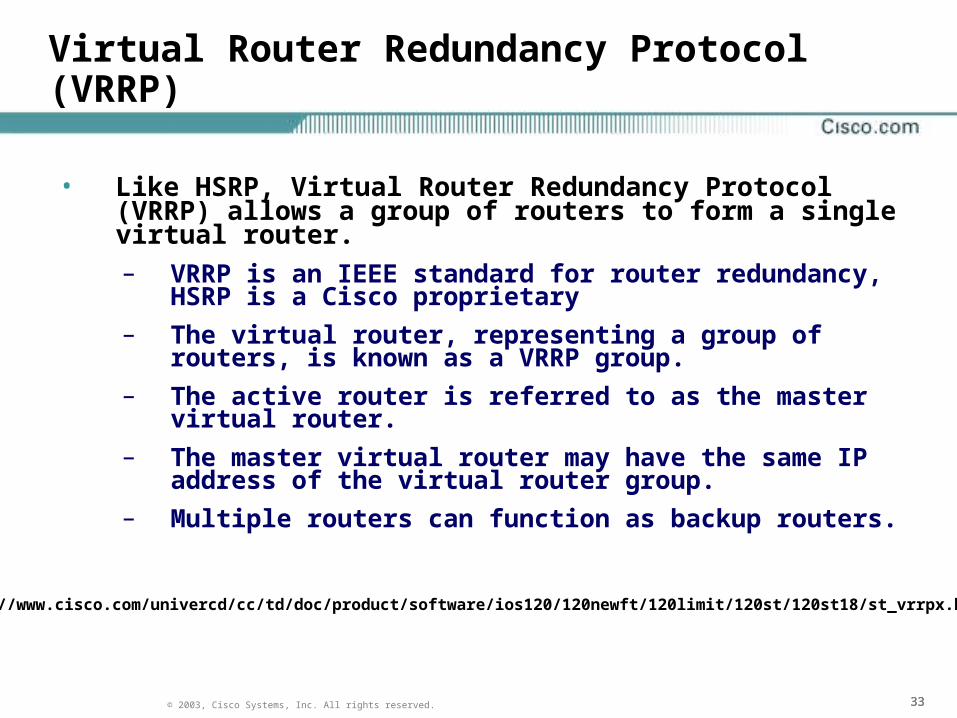
Virtual Router Redundancy Protocol (VRRP)
• Like HSRP, Virtual Router Redundancy Protocol (VRRP) allows a group of routers to form a single virtual router. – VRRP is an IEEE standard for router redundancy, HSRP
is a Cisco proprietary
– The virtual router, representing a group of routers, is known as a VRRP group.
– The active router is referred to as the master virtual router.
– The master virtual router may have the same IP address of the virtual router group.
– Multiple routers can function as backup routers.
http://www.cisco.com/univercd/cc/td/doc/product/software/ios120/120newft/120limit/120st/120st18/st_vrrpx.htm

343434© 2003, Cisco Systems, Inc. All rights reserved.
VRRP Example

353535© 2003, Cisco Systems, Inc. All rights reserved.
VRRP Redundancy Features
• VRRP provides redundancy for the real IP address of a router, or for a virtual IP address shared among the VRRP group members. – If a real IP address is used, the owning router
becomes the master.
– If a virtual IP address is used, the master is the router with the highest priority.
• A VRRP group has one master router and one or more backup routers.
• The master router uses VRRP messages to inform group members of the IP addresses of the backup routers.
363636© 2003, Cisco Systems, Inc. All rights reserved.
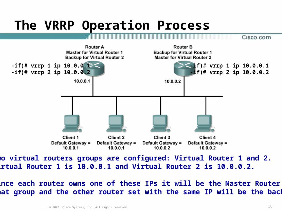
The VRRP Operation Process
-if)# vrrp 1 ip 10.0.0.1-if)# vrrp 2 ip 10.0.0.2
-if)# vrrp 1 ip 10.0.0.1-if)# vrrp 2 ip 10.0.0.2
Two virtual routers groups are configured: Virtual Router 1 and 2.Virtual Router 1 is 10.0.0.1 and Virtual Router 2 is 10.0.0.2.
Since each router owns one of these IPs it will be the Master Router forthat group and the other router set with the same IP will be the backup.

373737© 2003, Cisco Systems, Inc. All rights reserved.
The VRRP Operation Process
The priority of the Master Router is set to 255.Backup router priority values can range from 1 to 254; the defaultvalue is 100. The VRRP MAC address is 0000.5e00.01xx.
The master sends the advertisement on multicast 224.0.0.18 on a default interval of 1 second (advertisement interval).The master-down interval is the time interval for backup to declare the master down (seconds).

383838© 2003, Cisco Systems, Inc. All rights reserved.
VRRP Configuration
Master Router:
interface FastEthernet0/1 ip address 10.1.2.3 255.255.255.0 duplex auto speed auto vrrp 10 ip 10.1.2.3
Backup Router:
interface FastEthernet0/1 ip address 10.1.2.2 255.255.255.0 duplex auto speed auto vrrp 10 ip 10.1.2.3 vrrp 10 priority 150
Even with the higher priority, the routerbelow is still the backup because the router above is using its own IP address.

393939© 2003, Cisco Systems, Inc. All rights reserved.
Gateway Load Balancing Protocol (GLBP)
• While HSRP and VRRP provide gateway resiliency, the standby members of the redundancy group remain idle while the device is in standby mode.
– Only the active router for the HSRP and VRRP group forwards traffic for the virtual MAC.
– In order to provide load balancing, multiple groups must be created with each group pointing to different gateways.
http://www.cisco.com/univercd/cc/td/doc/product/software/ios122/122newft/122t/122t15/ft_glbp.htm

404040© 2003, Cisco Systems, Inc. All rights reserved.
Gateway Load Balancing Protocol (GLBP)
• Cisco designed GLBP allow for simultaneous use of multiple, available gateways, as well as automatic failover between those gateways.
• With GLBP, it is not necessary to configure multiple groups or assign different gateways to clients.

414141© 2003, Cisco Systems, Inc. All rights reserved.
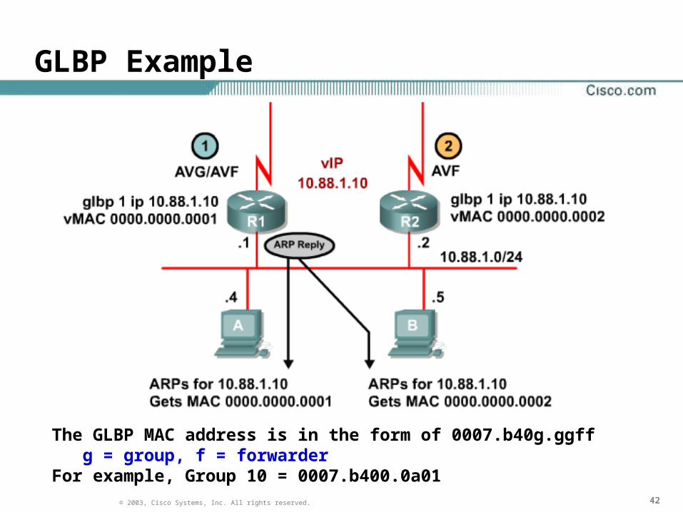
GLBP Operation
• The members of a GLBP group elect one gateway to be the Active Virtual Gateway (AVG) for that group. – The AVG is the router with the highest priority or IP addr.
– Other members of that group provide backup for the AVG.
• The AVG assigns a virtual MAC address to each member of the GLBP group. – The AVG answers all ARP requests sent from clients and
responds with one of the virtual MAC addresses of a member of the GLBP group.
– A GLBP group can have up to four group members.
– Each router in the GLBP group is called an Active Virtual Forwarder (AVF).
424242© 2003, Cisco Systems, Inc. All rights reserved.
GLBP Example
The GLBP MAC address is in the form of 0007.b40g.ggff g = group, f = forwarderFor example, Group 10 = 0007.b400.0a01

434343© 2003, Cisco Systems, Inc. All rights reserved.
GLBP Modes
• GLBP supports different modes of load balancing:
– Weighted load-balancing
• Uses the configured weight value
– Host-dependent
• Same host always uses the same virtual MAC
– Round-robin
• Each ARP reply contains the virtual MAC address of the next router in the group
• In the event that one of the AVFs becomes unavailable, the next AVF takes over for the one that went down.

444444© 2003, Cisco Systems, Inc. All rights reserved.
GLBP Example

454545© 2003, Cisco Systems, Inc. All rights reserved.
VRRP and GLBP Configuration
VRRP Implementation:
Switch(config)#interface vlan10 Switch(config-if)#ip address 10.1.10.5 255.255.255.0 Switch(config-if)#vrrp 10 ip 10.1.10.1
GLBP Implementation:
Router(config)#interface fa0/1 Router(config-if)#ip address 10.1.10.5 255.255.255.0 Router(config-if)#glbp 10 ip 10.1.10.1 Router(config-if)#glbp 10 priority 150 Router(config-if)#glbp 10 preemptRouter(config-if)#glbp 10 timers msec 250 msec 750

464646© 2003, Cisco Systems, Inc. All rights reserved.
Route Processor Redundancy

474747© 2003, Cisco Systems, Inc. All rights reserved.
Redundant Supervisor Engines
• A Catalyst switch can allow a standby supervisor engine to take over if the primary supervisor engine fails.
– In software, this capability is enabled by a feature called Route Processor Redundancy (RPR).
• RPR can run in one of two modes
– RPR and RPR+
• The active Supervisor Engine checks the IOS version of the redundant Supervisor Engine when it boots.
• If the image on the redundant Supervisor Engine is the same then RPR+ is used if they do not match, then RPR is used.
http://www.cisco.com/en/US/products/hw/switches/ps708/products_qanda_item09186a0080159963.shtml http://www.cisco.com/univercd/cc/td/doc/product/lan/cat6000/122sx/swcg/index.htm

484848© 2003, Cisco Systems, Inc. All rights reserved.
RPR+ vs. RPR
• RPR leaves the standby MSFC and PFC non operational until a failover occurs.
• RPR+ places the standby MSFC and PFC in an operational mode upon boot, thereby providing faster failover.
• RPR+ maintains synchronization of the running-configuration file between the two Supervisor Engines.
• Both RPR and RPR+ maintain synchronization of the startup-configuration file between the two Supervisor Engines.
http://www.cisco.com/univercd/cc/td/doc/product/lan/cat6000/122sx/swcg/redund.htm

494949© 2003, Cisco Systems, Inc. All rights reserved.
RPR Configuration

505050© 2003, Cisco Systems, Inc. All rights reserved.
Multilayer Switch Feature Card (MSFC)
• The Catalyst 6500 platform provides Layer 3 functionality through a Multilayer Switch Function card (MSFC) residing on the Supervisor Engine module.
– The MSFC3 which is integrated onto the Supervisor Engine 720.
– The MSFC3 runs Layer 2 protocols on one CPU and Layer 3 protocols on the second CPU.
• VLAN Trunking Protocol, routing protocols, multimedia services, security services etc…
• The MSFC builds the CEF Information Base table in software and downloads this table to the hardware or ASIC on the Policy Feature Card (PFC) and any installed Distributed Forwarding Card (DFC).

515151© 2003, Cisco Systems, Inc. All rights reserved.
Stateless Switchover Mode
• When a redundant supervisor engine runs in SSO mode, the redundant supervisor engine starts up in a fully-initialized state and synchronizes with the persistent configuration and the running config of the active sup engine. – This maintains the configuration of all Layer 2
protocols and the connection of all Layer 2 sessions.
– Layer 3 sessions will be delayed until the newly activated sup engine can repopulate its routing tables.
– SSO is supported in 12.2(20)EWA and later releases.
– Supported on Catalyst 4500 and 6500.
http://www.cisco.com/en/US/products/hw/switches/ps708/products_white_paper0900aecd801c5cd7.shtml

525252© 2003, Cisco Systems, Inc. All rights reserved.
Single Router Mode (SRM)
• In SRM redundancy, only the designated router (MSFC) is visible to the network at any given time.– Dual Router Mode (DRM) had both MFSCs active and used HSRP to
maintain an active and secondary relationship.
– This caused added complexity and peering problems.
• Instead, SRM uses an active designated router and a standby non-designated router.
• The non-designated router is booted up completely and participates in configuration synchronization, which is automatically enabled when entering SRM.
• The configuration of the non-designated router is exactly the same as the designated router, but its interfaces are kept in a "line down" state and are not visible to the network. – When the designated router fails, the non-designated router takes
over and brings up all its interfaces.
http://www.cisco.com/univercd/cc/td/doc/product/lan/cat6000/122sx/swcg/srmsso.htm

535353© 2003, Cisco Systems, Inc. All rights reserved.
Failure with SRM and SSO
• When the switch is powered on, SRM with SSO runs between the two Supervisor Engines.
– The Supervisor Engine that boots first becomes the active Supervisor.
• If the active Supervisor Engine 720 or MSFC3 fails, the redundant Supervisor Engine 720 and MSFC3 become active.
– The newly active Sup720 uses the existing PFC3 Layer 3 switching information to forward traffic while the newly active MSFC3 builds its routing table.
– Routing protocols have to then build the routing table for the newly activated Sup Engine.
• Packets that need to be routed are dropped until this is done.

545454© 2003, Cisco Systems, Inc. All rights reserved.
Nonstop Forwarding (NSF)
• Cisco NSF always runs with SSO and provides redundancy for Layer 3 traffic.
• The main purpose of NSF is to continue forwarding IP packets following a sup. engine switchover and the subsequent establishment of the routing protocols peering relationships. – Cisco NSF is supported by the BGP, OSPF, IS-IS and
EIGRP protocols for routing and is supported by CEF for forwarding.
– A networking device is NSF-aware if it is running NSF-compatible software.
– A device is NSF-capable if it has been configured to support NSF
http://www.cisco.com/univercd/cc/td/doc/product/lan/cat6000/122sx/swcg/nsfsso.htm

555555© 2003, Cisco Systems, Inc. All rights reserved.
Configuring NSF with SSO
Router> enable Router# configure terminal Enter configuration commands, one per line. End with CNTL/Z. Router(config)# redundancy Router(config-red)# mode sso Router(config-red)# end Router# show redundancy states Router# configure tRouter(config)# router ospf 1Router(config-router)# nsf

565656© 2003, Cisco Systems, Inc. All rights reserved.
Redundant Power

575757© 2003, Cisco Systems, Inc. All rights reserved.
6509 Startup showing Power in Redundancy Mode
00:00:54: SP: SP: Currently running ROMMON from S (Gold) region00:01:02: %SYS-SP-5-RESTART: System restarted --Cisco Internetwork Operating System SoftwareIOS (tm) s72033_sp Software (s72033_sp-SP-M), Version 12.2(14)SX1, EARLY DEPLOYMENT RELEASE TAC Support: http://www.cisco.com/tacCopyright (c) 1986-2003 by cisco Systems, Inc.Compiled Tue 27-May-03 20:48 by ccai00:01:03: %OIR-SP-6-INSPS: Power supply inserted in slot 100:01:03: %C6KPWR-SP-4-PSOK: power supply 1 turned on.00:01:03: %OIR-SP-6-INSPS: Power supply inserted in slot 200:01:03: %C6KPWR-SP-4-PSOK: power supply 2 turned on.00:01:03: %C6KPWR-SP-4-PSREDUNDANTBOTHSUPPLY: in power-redundancy mode, system is operating on both power supplies.00:01:04: %C6KENV-SP-4-FANHIOUTPUT: Version 2 high-output fan-tray is in effect00:01:09: %FABRIC-SP-5-FABRIC_MODULE_ACTIVE: the switching fabric module in slot 5 became active00:01:10: %DIAG-SP-6-RUN_COMPLETE: Module 5: Running Complete Diagnostics...00:01:30: %C6KENV-SP-4-CLOCKFAILED: clock 2 failed00:01:32: %DIAG-SP-6-DIAG_OK: Module 5: Passed Online Diagnostics00:01:33: %OIR-SP-6-INSCARD: Card inserted in slot 5, interfaces are now online00:01:33: %DIAG-SP-6-RUN_COMPLETE: Module 2: Running Complete Diagnostics...00:03:28: %DIAG-SP-6-DIAG_OK: Module 2: Passed Online Diagnostics00:03:28: %OIR-SP-6-INSCARD: Card inserted in slot 2, interfaces are now online00:04:00: %SNMP-5-COLDSTART: SNMP agent on host SouthCityPress is undergoing a cold start