1 2 simatic net - siemens ag · this system manual contains installation instructions for several...
TRANSCRIPT

___________________
___________________
___________________
___________________
___________________
___________________
___________________
___________________
SIMATIC NET
Industrial Remote Communication Remote Networks SCALANCE M874, M876
Operating Instructions
08/2016 C79000-G8976-C331-06
Preface
Security recommendations 1
Description of the device 2
Installation 3
Connecting up 4
Dimension drawings 5
Technical specifications 6
Approvals A

Siemens AG Division Process Industries and Drives Postfach 48 48 90026 NÜRNBERG GERMANY
C79000-G8976-C331-06 Ⓟ 10/2016 Subject to change
Copyright © Siemens AG 2013 - 2016. All rights reserved
Legal information Warning notice system
This manual contains notices you have to observe in order to ensure your personal safety, as well as to prevent damage to property. The notices referring to your personal safety are highlighted in the manual by a safety alert symbol, notices referring only to property damage have no safety alert symbol. These notices shown below are graded according to the degree of danger.
DANGER indicates that death or severe personal injury will result if proper precautions are not taken.
WARNING indicates that death or severe personal injury may result if proper precautions are not taken.
CAUTION indicates that minor personal injury can result if proper precautions are not taken.
NOTICE indicates that property damage can result if proper precautions are not taken.
If more than one degree of danger is present, the warning notice representing the highest degree of danger will be used. A notice warning of injury to persons with a safety alert symbol may also include a warning relating to property damage.
Qualified Personnel The product/system described in this documentation may be operated only by personnel qualified for the specific task in accordance with the relevant documentation, in particular its warning notices and safety instructions. Qualified personnel are those who, based on their training and experience, are capable of identifying risks and avoiding potential hazards when working with these products/systems.
Proper use of Siemens products Note the following:
WARNING Siemens products may only be used for the applications described in the catalog and in the relevant technical documentation. If products and components from other manufacturers are used, these must be recommended or approved by Siemens. Proper transport, storage, installation, assembly, commissioning, operation and maintenance are required to ensure that the products operate safely and without any problems. The permissible ambient conditions must be complied with. The information in the relevant documentation must be observed.
Trademarks All names identified by ® are registered trademarks of Siemens AG. The remaining trademarks in this publication may be trademarks whose use by third parties for their own purposes could violate the rights of the owner.
Disclaimer of Liability We have reviewed the contents of this publication to ensure consistency with the hardware and software described. Since variance cannot be precluded entirely, we cannot guarantee full consistency. However, the information in this publication is reviewed regularly and any necessary corrections are included in subsequent editions.

SCALANCE M874, M876 Operating Instructions, 08/2016, C79000-G8976-C331-06 3
Preface
Purpose of the Operating Instructions These compact operating instructions contain information with which you will be able to install and connect up a device of the SCALANCE M874, M876 product line. The configuration and the integration of the device in a network are not described in these instructions.
Validity of the manual These operating instructions apply to the following devices:
● SCALANCE M874-2
● SCALANCE M874-3
● SCALANCE M876-3
● SCALANCE M876-4
Naming of the devices Classification Description Terms used Product line For all devices and variants of all product
groups within the SCALANCE M-800 prod-uct line, the term M-800 is used.
M-800
Product group For all devices and variants of a product group, only the product group is used.
• M874 stands for M874-2, M874-3
• M876 stands for M876-3, M876-4
• M87x stands for M874-2, , M874-3, M876-3, M876-4
Device For a device, only the device name is used. M874-2 M874-3 M876-3 M876-4

Preface
SCALANCE M874, M876 4 Operating Instructions, 08/2016, C79000-G8976-C331-06
Further documentation ● System manual "Industrial Ethernet"
The system manual contains information on other SIMATIC NET products that you can operate along with the devices of this product line in an Industrial Ethernet network.
There, you will find among other things optical performance data of the communications partner that you require for the installation.
The "SIMATIC NET Industrial Ethernet" system manual can be found on the Internet pages of Siemens Industry Online Support under the following entry ID:27069465 (http://support.automation.siemens.com/WW/view/wn/27069465)
● "Passive network components" system manual
This system manual contains installation instructions for several of the most common components and guidelines for setting up networked automation plants in buildings.
The "Passive Network Components" system manual can be found on the Internet pages of Siemens Industry Online Support under the following entry ID:84922825 (http://support.automation.siemens.com/WW/view/en/84922825)
SIMATIC NET manuals You will find SIMATIC NET manuals on the Internet pages of Siemens Industry Online Support:
● using the search function:
Link to Siemens Industry Online Support (http://support.automation.siemens.com/)
Enter the entry ID of the relevant manual as the search item.
● In the navigation panel on the left hand side in the area "Industrial Communication":
Link to the area "Industrial Communication" (http://support.automation.siemens.com/WW/view/en/10805878/133400)
Go to the required product group and make the following settings: tab "Entry list", Entry type "Manuals"
You will find the documentation for the SIMATIC NET products relevant here on the data medium that ships with some products:
● Product CD / product DVD
● SIMATIC NET Manual Collection
You will find the article numbers for the Siemens products of relevance here in the following catalogs:
● SIMATIC NET Industrial Communication / Industrial Identification, catalog IK PI
● SIMATIC Products for Totally Integrated Automation and Micro Automation, catalog ST 70
● Industry Mall - catalog and ordering system for automation and drive technology, Online catalog (http://eb.automation.siemens.com/)
You can request the catalogs and additional information from your Siemens representative.

Preface
SCALANCE M874, M876 Operating Instructions, 08/2016, C79000-G8976-C331-06 5
Security information Siemens provides products and solutions with industrial security functions that support the secure operation of plants, systems, machines and networks.
In order to protect plants, systems, machines and networks against cyber threats, it is necessary to implement – and continuously maintain – a holistic, state-of-the-art industrial security concept. Siemens’ products and solutions only form one element of such a concept.
Customer is responsible to prevent unauthorized access to its plants, systems, machines and networks. Systems, machines and components should only be connected to the enterprise network or the internet if and to the extent necessary and with appropriate security measures (e.g. use of firewalls and network segmentation) in place.
Additionally, Siemens’ guidance on appropriate security measures should be taken into account. For more information about industrial security, please visit Link: (http://www.siemens.com/industrialsecurity)
Siemens’ products and solutions undergo continuous development to make them more secure. Siemens strongly recommends to apply product updates as soon as available and to always use the latest product versions. Use of product versions that are no longer supported, and failure to apply latest updates may increase customer’s exposure to cyber threats.
To stay informed about product updates, subscribe to the Siemens Industrial Security RSS Feed under Link: (http://www.siemens.com/industrialsecurity).
Trademarks The following and possibly other names not identified by the registered trademark sign ® are registered trademarks of Siemens AG:
SCALANCE, SINEMA, KEY-PLUG, C-PLUG
License conditions
Note Open source software
Read the license conditions for open source software carefully before using the product.
You will find license conditions in the following documents on the supplied data medium:
● OSS_ScalanceM-800_S615_86.htm
SIMATIC NET glossary Explanations of many of the specialist terms used in this documentation can be found in the SIMATIC NET glossary.
You will find the SIMATIC NET glossary on the Internet at the following address:
50305045 (http://support.automation.siemens.com/WW/view/en/50305045)

Preface
SCALANCE M874, M876 6 Operating Instructions, 08/2016, C79000-G8976-C331-06
SCALANCE M874, M876 Operating Instructions, 08/2016, C79000-G8976-C331-06 7
Table of contents
Preface ................................................................................................................................................... 3
1 Security recommendations ...................................................................................................................... 9
2 Description of the device ....................................................................................................................... 15
2.1 Product characteristics............................................................................................................ 15
2.2 Accessories ............................................................................................................................. 17
2.3 Terminals ................................................................................................................................ 20
2.4 LED display ............................................................................................................................. 22 2.4.1 SCALANCE M874-2, M874-3 ................................................................................................. 22 2.4.2 SCALANCE M876-3, M876-4 ................................................................................................. 25
2.5 SET button .............................................................................................................................. 27
2.6 C-PLUG and KEY-PLUG ........................................................................................................ 29
3 Installation ............................................................................................................................................ 31
3.1 Securing the housing .............................................................................................................. 33
3.2 Wall mounting ......................................................................................................................... 34
3.3 Installation on the DIN rail ....................................................................................................... 36
3.4 Installing on the S7-300 standard rail ..................................................................................... 38
3.5 Installing on the S7-1500 standard rail ................................................................................... 40
3.6 Installation on a desktop pedestal .......................................................................................... 42
4 Connecting up ....................................................................................................................................... 45
4.1 Safety when connecting up ..................................................................................................... 46
4.2 SIM card .................................................................................................................................. 48
4.3 Power supply .......................................................................................................................... 49
4.4 Grounding ............................................................................................................................... 51
4.5 Digital input/output .................................................................................................................. 52
4.6 Antennas ................................................................................................................................. 55
4.7 Ethernet port ........................................................................................................................... 58
4.8 Inserting and removing the PLUG .......................................................................................... 59
5 Dimension drawings .............................................................................................................................. 61
5.1 SCALANCE M874-2, M874-3 ................................................................................................. 61
5.2 SCALANCE M876-3, M876-4 ................................................................................................. 63
6 Technical specifications ........................................................................................................................ 65
6.1 GPRS/EDGE router SCALANCE M874-2 .............................................................................. 65

Table of contents
SCALANCE M874, M876 8 Operating Instructions, 08/2016, C79000-G8976-C331-06
6.2 HSPA+ router SCALANCE M874-3 ....................................................................................... 68
6.3 HSPA+ router SCALANCE M876-3 ....................................................................................... 71
6.4 LTE router SCALANCE M876-4 ............................................................................................ 74
6.5 LTE router SCALANCE M876-4 (NAM) ................................................................................. 78
6.6 Antenna gain .......................................................................................................................... 82
A Approvals ............................................................................................................................................. 85
A.1 EU declaration of conformity .................................................................................................. 87 A.1.1 ATEX ...................................................................................................................................... 88 A.1.2 RoHS ...................................................................................................................................... 88 A.1.3 R&TTE / RED ......................................................................................................................... 88 A.1.3.1 Protection of health and safety .............................................................................................. 88 A.1.4 Products ................................................................................................................................. 90
A.2 RCM / C-TICK ........................................................................................................................ 91
A.3 ATEX ...................................................................................................................................... 92
A.4 IECEx ..................................................................................................................................... 93
A.5 Conformity with FCC .............................................................................................................. 94
A.6 RSS-210 Industry of Canada ................................................................................................. 96
A.7 FM certification ....................................................................................................................... 97
A.8 UL certification (product safety) ............................................................................................. 98
A.9 UL HAZ. LOC certification (explosion protection) .................................................................. 99
A.10 EAC ...................................................................................................................................... 100
Index ................................................................................................................................................... 101

SCALANCE M874, M876 Operating Instructions, 08/2016, C79000-G8976-C331-06 9
Security recommendations 1
To prevent unauthorized access, note the following security recommendations.
General ● You should make regular checks to make sure that the device meets these
recommendations and/or other security guidelines.
● Evaluate your plant as a whole in terms of security. Use a cell protection concept with suitable products:
Link: (http://www.industry.siemens.com/topics/global/en/industrial-security/network-security/Pages/Default.aspx)
● When the internal and external network are disconnected, an attacker cannot access internal data from the outside. Therefore operate the device only within a protected network area.
● Operate the device only within a protected network area.
● Use VPN to encrypt and authenticate communication from and to the devices.
● For data transmission via a non-secure network use an encrypted VPN tunnel (IPsec, Open VPN).
● Separate connections correctly (WBM. Telnet, SSH etc.).
Physical access ● Limit physical access to the device to qualified personnel.
The memory card or the PLUG (C-PLUG, KEY-PLUG) contains sensitive data such as certificates, keys etc. that can be read out and modified.
● Lock unused physical ports on the device. Unused ports can be used to gain forbidden access to the plant.

Security recommendations
SCALANCE M874, M876 10 Operating Instructions, 08/2016, C79000-G8976-C331-06
Software (security functions) ● Keep the software up to date. Check regularly for security updates of the product.
You will find information on this on the Internet pages "Industrial Security (http://www.siemens.com/industrialsecurity)".
● Inform yourself regularly about security advisories and bulletins published by Siemens ProductCERT (http://www.siemens.com/cert/en/cert-security-advisories.htm).
● Only activate protocols that you really require to use the device.
● The option of VLAN structuring provides good protection against DoS attacks and unauthorized access. Check whether this is practical or useful in your environment.
● Restrict access to the device by firewall, VPN (IPsec, OSINEMA RC) and NAT.
● Use a central logging server to log changes and accesses. Operate your logging server within the protected network area and check the logging information regularly.
Passwords ● Define rules for the use of devices and assignment of passwords.
● Regularly update passwords and keys to increase security.
● Change all default passwords for users before you operate the device.
● Only use passwords with a high password strength. Avoid weak passwords for example password1, 123456789, abcdefgh.
● Make sure that all passwords are protected and inaccessible to unauthorized personnel.
● Do not use the same password for different users and systems or after it has expired.
Keys and certificates This section deals with the security keys and certificates you require to set up SSL, VPN (IPsec, OpenVPN) and SINEMA RC.
● The device contains a pre-installed SSL certificate with key. Replace this certificate with a self-made certificate with key. We recommend that you use a certificate signed by a reliable external or internal certification authority.
● Use the certification authority including key revocation and management to sign the certificates.
● Make sure that user-defined private keys are protected and inaccessible to unauthorized persons.
● Verify certificates and fingerprints on the server and client to prevent "man in the middle" attacks.
● It is recommended that you use password-protected certificates in the PKCS #12 format
● It is recommended that you use certificates with a key length of at least 2048 bits.
● Change keys and certificates immediately, if there is a suspicion of compromise.

Security recommendations
SCALANCE M874, M876 Operating Instructions, 08/2016, C79000-G8976-C331-06 11
Secure/non-secure protocols ● Avoid or disable non-secure protocols, for example Telnet and TFTP. For historical
reasons, these protocols are still available, however not intended for secure applications. Use non-secure protocols on the device with caution.
● Avoid or disable non-secure protocols. Check whether use of the following protocols is necessary:
– Broadcast pings
– Non authenticated and unencrypted interfaces
– ICMP (redirect)
– LLDP
– Syslog
– DHCP Options 66/67
– TFTP
● The following protocols provide secure alternatives:
– SNMPv1/v2 → SNMPv3
Check whether use of SNMPv1 is necessary. SNMPv1 is classified as non-secure. Use the option of preventing write access. The product provides you with suitable setting options.
If SNMP is enabled, change the community names. If no unrestricted access is necessary, restrict access with SNMP.
– HTTP → HTTPS
– Telnet → SSH
● Use secure protocols when access to the device is not prevented by physical protection measures.
● To prevent unauthorized access to the device or network, take suitable protective measures against non-secure protocols.
● If you require non-secure protocols and services, activate these at interfaces that are located within a protected network area.
● Using a firewall, restrict the services and protocols available to the outside to a minimum.
● For the DCP function, enable the "DCP read-only" mode after commissioning.

Security recommendations
SCALANCE M874, M876 12 Operating Instructions, 08/2016, C79000-G8976-C331-06
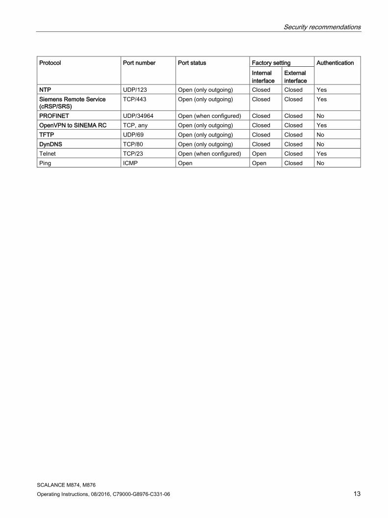
Available protocols per port The following list provides you with an overview of the open ports on this device. Keep this in mind when configuring a firewall.
The table includes the following columns:
● Protocol
All protocols that the device supports
● Port number
Port number assigned to the protocol
● Port status
– Open
The port is always open and cannot be closed.
– Open (when configured)
The port is open if it has been configured.
● Factory setting
– Open
The factory setting of the port is "Open".
– Closed
The factory setting of the port is "Closed".
● Authentication
Specifies whether or not the protocol is authenticated during access.
With some protocols the port can be open but access is prevented by a predefined IP package filter rule. You will find further information on the predefined IP package rules in "Security > Firewall > Predefined IPv4"
Protocol Port number Port status Factory setting Authentication
Internal interface
External interface
SSH TCP/22 Open (when configured) Open Closed Yes HTTP TCP/80 Open (when configured) Open Closed Yes HTTPS TCP/443 Open Open Closed Yes SNTP UDP/123 Open (only outgoing) Closed Closed No SNMP UDP/161 Open (when configured) Open Closed Yes DNS TCP/53 Open (when configured) Open Closed No
UDP/53 Open (when configured) Open Closed No Syslog UDP/514 Open (only outgoing) Closed Closed No IPsec UDP/500
UDP/4500 Open (when configured) Closed Open Yes
DHCP UDP/67 UDP/68
Open (when configured) Open Closed No
Security recommendations
SCALANCE M874, M876 Operating Instructions, 08/2016, C79000-G8976-C331-06 13
Protocol Port number Port status Factory setting Authentication Internal interface
External interface
NTP UDP/123 Open (only outgoing) Closed Closed Yes Siemens Remote Service (cRSP/SRS)
TCP/443 Open (only outgoing) Closed Closed Yes
PROFINET UDP/34964 Open (when configured) Closed Closed No OpenVPN to SINEMA RC TCP, any Open (only outgoing) Closed Closed Yes TFTP UDP/69 Open (only outgoing) Closed Closed No DynDNS TCP/80 Open (only outgoing) Closed Closed No Telnet TCP/23 Open (when configured) Open Closed Yes Ping ICMP Open Open Closed No

Security recommendations
SCALANCE M874, M876 14 Operating Instructions, 08/2016, C79000-G8976-C331-06

SCALANCE M874, M876 Operating Instructions, 08/2016, C79000-G8976-C331-06 15
Description of the device 2 2.1 Product characteristics
Interfaces Functionality M874-2
M874-3 M876-3 M876-4
Connectors for external anten-nas
1 SMA antenna connector
2 SMA antenna connectors
Ethernet interface 2 x RJ-45 10 / 100 Mbps 4 x RJ-45 10 / 100 Mbps Digital input/output 1/1 1/1
Scope of delivery The following components ship with the product:
● One device
● A 5-pin terminal block for the power supply
● A 2-pin terminal block for the digital output
● A 2-pin terminal block for the digital input
● Product CD
Note Not included with the product
The following components do not ship with the product: • KEY-PLUG / C-PLUG
You will find more detailed information in "C-PLUG and KEY-PLUG (Page 29)". • Antennas
You will find more detailed information in "Accessories (Page 17)". • Standard SIM card
Use the SIM card from the chosen mobile wireless provider

Description of the device 2.1 Product characteristics
SCALANCE M874, M876 16 Operating Instructions, 08/2016, C79000-G8976-C331-06
Article numbers Type Article number Description SCALANCE M874-2 6GK5 874-2AA00-2AA2 Mobile wireless router for 2G (EDGE) SCALANCE M874-3 6GK5 874-3AA00-2AA2 Mobile wireless router for 3G (HSPA+) SCALANCE M876-3
6GK5 876-3AA02-2BA2 Mobile wireless router for 3G (HSPA+) with an-tenna diversity
6GK5876-3AA02-2EA2 (Korea)
SCALANCE M876-4 6GK5 876-4AA00-2BA2 Mobile wireless router for 4G (LTE) with antenna diversity 6GK5876-4AA00-2DA2
(NAM: North America)
Unpacking and checking
WARNING
Do not use any parts that show evidence of damage
If you use damaged parts, there is no guarantee that the device will function according to the specification.
If you use damaged parts, this can lead to the following problems: • Injury to persons • Loss of the approvals • Violation of the EMC regulations
Use only undamaged parts.
1. Make sure that the package is complete.
2. Check all the parts for transport damage.

Description of the device 2.2 Accessories
SCALANCE M874, M876 Operating Instructions, 08/2016, C79000-G8976-C331-06 17
2.2 Accessories You will find further information on the accessories program for the M-800 in the Industry Mall (https://eb.automation.siemens.com/goos/WelcomePage.aspx?regionUrl=/en&language=en). Type Properties Article number C-PLUG Exchangeable storage medium (32 MB) for the
configuration data 6GK1900-0AB00
Exchangeable storage medium (256 MB) for the configuration data
6GK1900-0AB10
KEY-PLUG SINEMA RC Exchangeable storage medium (256 MB) to enable the connection functionality to SINEMA Remote Connect and for storing configuration data.
6GK5908-0PB00
Desktop pedestal SCALANCE M-800 desktop pedestal for table mounting for SCALANCE M812 / M816 / M874-X / M876-X / S615
6GK5898-8MD00
Antennas Type Properties Article number ANT794-3M Flat antenna for GSM networks, for tri-band
with 900 / 1800 / 1900 MHz; weatherproof for indoor and outdoor areas; 1.2 m connecting cable connected permanently to the antenna; SMA connector, including adhesive mounting tape
6NH9870-1AA00
ANT794-4MR Omnidirectional antenna for GSM (2G), UMTS (3G) and LTE(4G); weatherproof for indoor and outdoor areas; 5 m connecting cable connected permanently to the antenna; SMA connector, including installation bracket, screws, wall plugs
6NH9860-1AA00
ANT 896-4MA IRC antenna ANT 896-4MA for GSM (2G), UMTS (3G) and LTE (4G),omnidirectional characteristic, radial swiveling, with additional joint, antenna gain: 2 dBi, incl. SMA connect-or, IP54, (-40 to +85 °C), note national ap-provals, for direct mounting with SMA connector; package contains: 1X ANT896-4MA compact instructions on paper German / English, scope of delivery 1x ANT896-6MA
6GK5896-4MA00-0AA3
ANT 896-4ME IRC antenna ANT 896-4MA for GSM (2G), UMTS (3G) and LTE (4G) networks, omnidi-rectional characteristic incl. N female connect-or 3 dBi; IP66 (-40 to +70 °C), note national approvals; mounting on cabinet; compact instructions on paper German/English;; scope of delivery: 1X ANT896-4ME
6GK5896-4ME00-0AA0

Description of the device 2.2 Accessories
SCALANCE M874, M876 18 Operating Instructions, 08/2016, C79000-G8976-C331-06
Type Properties Article number ANT 896-6MH Mobile wireless antenna ANT 896-6MH for
GSM (2G), UMTS (3G) and LTE (4G) net-works, suitable for railway applications, omni-directional characteristic incl. N-female connector; 5/6 dBi; IP69K (-40 to +85 °C), note national approvals; mounting on vehicle roof compact instructions on paper Ger-man/English; scope of delivery: 1X ANT896-6MH
6GK5896-6MH00-0AA0
ANT 896-6MM Mobile wireless antenna ANT 896-6MM for GSM (2G), UMTS (3G), LTE EU (4G) net-works, GPS and WLAN 2.4/5 GHz, omnidirec-tional characteristic incl. 3x pigtail with QMA connector antenna gain: 5/8 dBi; IP69K (-40 to +85 °C), note national approvals; mounting on vehicle roof; compact instructions on paper German/English; scope of delivery: 1x ANT896-6MM
6GK5896-6MM00-0AA0
SIMATIC NET CABLE N-CONNECT/SMA
Flexible connecting cable SCALNCE M anten-na, preassembled, various lengths.
0.3 meters 6XV1875-5LE30 1 meter 6XV1875-5LH10
2 meters 6XV1875-5LH20 5 meters 6XV1875-5LH50
Flexible connecting cable SCALNCE M anten-na, preassembled, various lengths, railway applications.
1 meter 6XV1875-5UH10 2 meters 6XV1875-5UH20 5 meters 6XV1875-5UH50
SIMATIC NET N-CONNECT MALE/MALE
Flexible connecting cable e.g. for 2 RCOAX segments, various lengths.
1 meter 6XV1875-5AH10 2 meters 6XV1875-5AH20 5 meters 6XV1875-5AH50 5 meters 6XV1875-5AH50
10 meters 6XV1875-5AN10 Flexible connecting cable e.g. for 2 RCOAX segments, various lengths, railway applica-tions
1 meter 6XV1875-5SH10 2 meters 6XV1875-5SH20 5 meters 6XV1875-5SH50 5 meters 6XV1875-5SH50

Description of the device 2.2 Accessories
SCALANCE M874, M876 Operating Instructions, 08/2016, C79000-G8976-C331-06 19
Type Properties Article number SIMATIC NET CABLE QMA/N-CONNECT
Flexible adapter cable, preassembled with two connectors QMA/N connect male/female, length 1 m, pack of 3
6XV1875-5JH10
Flexible adapter cable, preassembled with two connectors QMA/N connect male/female, railway applications, length 1 m, pack of 1
6XV1875-5VH10
SIMATIC NET WINKELADAPTER SMA/SMA MALE/ FEMALE
Angled adapter with two connectors SMA male and SMA female. This adapter simplifies the mounting of an antenna connecting cable on a SCALANCE M and e.g. allows a space-saving feed from above or below.
6GK5898-1CV00-4AA0
IE FC RJ45 PLUG RJ-45 connector (10/100 Mbps) with rugged metal housing and FC connection technology for IE FC cable 2x2 180 degree cable outlet various package sizes
Pack of 1 6GK1901-1BB10-2AA0 Pack of 10 6GK1901-1BB10-2AB0 Pack of 50 6GK1901-1BB10-2AE0
SIMATIC NET Lightning Protector LP798-1N
Lightning protection element with N/N fe-male/female connector, IP65 (-40 to +100 °C), 0 to 6 GHz with gas discharge technology for SCALANCE W and M antennas, compact instructions on paper German/English
6GK5798-2LP00-2AA6
SIMATIC N-Connect/N-Connect
Female / female panel feedthrough 2.4.GHz and 5 GHz cabinet feedthrough for wall thick-ness maximum 4.5 mm
6GK5798-2PP00-2AA6

Description of the device 2.3 Terminals
SCALANCE M874, M876 20 Operating Instructions, 08/2016, C79000-G8976-C331-06
2.3 Terminals The device has the following terminal strips.
Connectors and terminal markings
① Input for the power supply L1, M2, L2, M2
Terminal strip with five screw connectors
② Functional ground
③ Digital input +DI, -DI Terminal strip with two screw connectors
④ Digital output +DO, -DO Terminal strip with two screw connectors

Description of the device 2.3 Terminals
SCALANCE M874, M876 Operating Instructions, 08/2016, C79000-G8976-C331-06 21
Terminals ① - ④ Screwdriver blade 0.4 x 2.5 (DIN 5264) Clamping screw M2 Tightening torque 0.2 Nm - 0.25 Nm AWG 28 AWG 16 AWG Wire end ferrule without plastic collar to DIN 46228/1
0.2 mm2 1.5 mm2
Wire end ferrule with plastic collar to DIN 46228/4
0.2 mm2 1.5 mm2
Stripped length 7 mm 7 mm

Description of the device 2.4 LED display
SCALANCE M874, M876 22 Operating Instructions, 08/2016, C79000-G8976-C331-06
2.4 LED display
2.4.1 SCALANCE M874-2, M874-3
LED Status Meaning F OFF
No fault/error.
ON
The device is starting up or an error has occurred. Possible errors/faults: • Wrong PIN number
Flashing
The bootloader waits in this state for a new firmware file that you can download using TFTP.

Description of the device 2.4 LED display
SCALANCE M874, M876 Operating Instructions, 08/2016, C79000-G8976-C331-06 23
LED Status Meaning L
OFF
Device turned off, no power supply.
ON
Device turned on, power supply present.
SC
OFF
SIM card OK, no connection.
ON
Wrong PIN number / SIM card error
ON
Connection established
Q OFF
No reception Signal strength: < -109 dBm
Flashing
Signal strength bad: -89 dBm to -109 dBm
On
Signal strength medium: -73 dBm to -89 dBm
ON
Signal strength good: > -73 dBm
OFF
No VPN connection is established.
ON
All configured VPN connections are established.
Flashing
Only some of the configured VPN connections are established.
P1/P2 OFF
Ethernet connection to local computer or LAN not established
ON
Ethernet connection to local computer or LAN established
ON
Device receiving / sending data

Description of the device 2.4 LED display
SCALANCE M874, M876 24 Operating Instructions, 08/2016, C79000-G8976-C331-06
LED Status Meaning DI OFF
Digital input inactive
ON
Digital input active.
DO OFF
Digital output inactive
ON
Digital output active.

Description of the device 2.4 LED display
SCALANCE M874, M876 Operating Instructions, 08/2016, C79000-G8976-C331-06 25
2.4.2 SCALANCE M876-3, M876-4
LED Status Meaning F OFF
No fault/error.
ON
The device is starting up or an error has occurred. Possible errors/faults: • Wrong PIN number
Flashing
The bootloader waits in this state for a new firmware file that you can download using TFTP.
L
OFF
Device turned off, no power supply.
ON
Device turned on, power supply present.

Description of the device 2.4 LED display
SCALANCE M874, M876 26 Operating Instructions, 08/2016, C79000-G8976-C331-06
LED Status Meaning SC
OFF
SIM card OK, no connection.
ON
Wrong PIN number / SIM card error
ON
Connection established
Q OFF
No reception Signal strength: < -109 dBm
Flashing
Signal strength bad: -89 dBm to -109 dBm
On
Signal strength medium: -73 dBm to -89 dBm
ON
Signal strength good: > -73 dBm
OFF
No VPN connection is established.
ON
All configured VPN connections are established.
Flashing
Only some of the configured VPN connections are established.
P1 P2 P3 P4
OFF
Ethernet connection to local computer or LAN not established
ON
Ethernet connection to local computer or LAN established
ON
Device receiving / sending data
DI OFF
Digital input inactive
ON
Digital input active.
DO OFF
Digital output inactive
ON
Digital output active.

Description of the device 2.5 SET button
SCALANCE M874, M876 Operating Instructions, 08/2016, C79000-G8976-C331-06 27
2.5 SET button With a SCALANCE M.800, the SET button is on the front of the housing beside the LED display.
The SET button has the following functions:
● Restart
Hold down the button for longer than 3 seconds to run a restart.
● Loading new firmware
If the normal procedure with the "Load & Save" menu of Web Based Management does not work, the reset button can be used to load new firmware. This situation can occur if there is a power outage during the normal firmware update.
– Hold down the button until the red fault LED (F) starts to flash after approximately 3 seconds.
– Now release the button. The bootloader waits in this state for a new firmware file that you can download using TFTP.

Description of the device 2.5 SET button
SCALANCE M874, M876 28 Operating Instructions, 08/2016, C79000-G8976-C331-06
You will find more information in the section "Service and Maintenance" in the SCALANCE M-800 Web Based Management configuration manual.
● Reset to factory defaults
– Hold down the button until the red fault LED (F) stops flashing after approximately 10 seconds and is permanently lit.
– Now release the button and wait until the fault LED (F) goes off again. The device then starts automatically with the factory settings and can be reached via the IP address 192.168.1.1.
You will find more information in the section "Service and Maintenance" in the SCALANCE M-800 Web Based Management configuration manual.
WARNING
EXPLOSION HAZARD
Do not press the SET button if there is a potentially explosive atmosphere.

Description of the device 2.6 C-PLUG and KEY-PLUG
SCALANCE M874, M876 Operating Instructions, 08/2016, C79000-G8976-C331-06 29
2.6 C-PLUG and KEY-PLUG
How it works The C-PLUG or KEY-PLUG is used to transfer the configuration of the old device to the new device when a device is replaced.
NOTICE
Do not remove or insert a C-PLUG / KEY-PLUG during operation!
A PLUG may only be removed or inserted when the device is turned off. The device checks whether or not a PLUG is present at one second intervals. If it is detected that the PLUG was removed, there is a restart.
If a valid KEY-PLUG was inserted in the device, the device changes to a defined error state following the restart.
When the new device starts up with the PLUG, it then continues automatically with exactly the same configuration as the old device. One exception to this can be the IP configuration if it is set over DHCP and the DHCP server has not been reconfigured accordingly.
A reconfiguration is necessary if you use functions based on MAC addresses. If an incorrect PLUG, for example from another product or a damaged PLUG is inserted, the device signals an error with the "F" LED.
You can either remove the PLUG again or select the option to reformat the PLUG.
In terms of the PLUG, devices work in two modes:
● Without PLUG
The device stores the configuration in internal memory. This mode is active when no PLUG is inserted.
● With PLUG
The configuration stored on the PLUG is displayed in WBM in "Information > PLUG". If changes are made to the configuration, the device stores the configuration directly on the PLUG and in the internal memory. This mode is active as soon as a PLUG is inserted. As soon as the device is started with a PLUG inserted, the device starts up with the configuration data on the PLUG.
License information on the KEY-PLUG In addition to the configuration, the KEY-PLUG also contains a license that allows the use of Siemens Remote Services.
See also Inserting and removing the PLUG (Page 59)
Accessories (Page 17)

Description of the device 2.6 C-PLUG and KEY-PLUG
SCALANCE M874, M876 30 Operating Instructions, 08/2016, C79000-G8976-C331-06

SCALANCE M874, M876 Operating Instructions, 08/2016, C79000-G8976-C331-06 31
Installation 3
Safety notices When installing the device, keep to the safety notices listed below.
WARNING
If a device is operated in an ambient temperature of more than 50 °C, the temperature of the device housing may be higher than 70 °C. The device must therefore be installed so that it is only accessible to service personnel or users that are aware of the reason for restricted access and the required safety measures at an ambient temperature higher than 50 °C.
Safety notices on use in hazardous areas
General safety notices relating to protection against explosion
WARNING
EXPLOSION HAZARD
SUBSTITUTION OF COMPONENTS MAY IMPAIR SUITABILITY FOR CLASS I, DIVISION 2 OR ZONE 2.
WARNING
The device may only be operated in an environment with pollution degree 1 or 2 (see IEC 60664-1).
WARNING
When used in hazardous environments corresponding to Class I, Division 2 or Class I, Zone 2, the device must be installed in a cabinet or a suitable enclosure.
Installation
SCALANCE M874, M876 32 Operating Instructions, 08/2016, C79000-G8976-C331-06
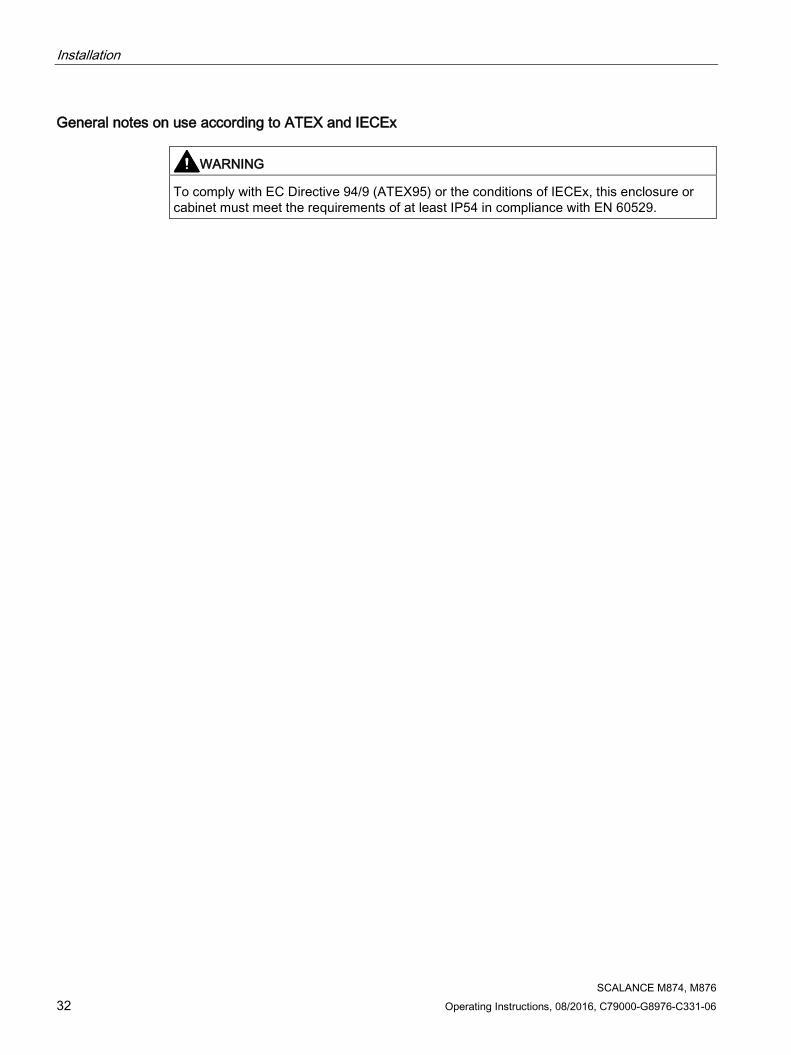
General notes on use according to ATEX and IECEx
WARNING
To comply with EC Directive 94/9 (ATEX95) or the conditions of IECEx, this enclosure or cabinet must meet the requirements of at least IP54 in compliance with EN 60529.

Installation 3.1 Securing the housing
SCALANCE M874, M876 Operating Instructions, 08/2016, C79000-G8976-C331-06 33
3.1 Securing the housing
Types of installation For the device, you have the following options:
● Wall mounting (no ceiling mounting)
● Installation on a DIN rail
● Installing on the S7-300 standard rail
● Installing on the S7-1500 standard rail
● Mounting on a pedestal
Strain relief for the cables
Regardless of the type of installation, make sure that there is suitable strain relief for the connecting cable.
Shielding of cables
If cables are installed permanently, it is advisable to remove the insulation of the shielded cable and to establish contact on the shield/PE conductor bar.
Permitted installation direction
● Vertical installation (ventilation openings at the top and bottom)
Clearances
Keep to the minimum clearances to other components or to walls of a housing so that the convection ventilation of the device is not blocked.
● Below at least 10 cm
● Above at least 10 cm
● M876-3
– At an ambient temperature up to 60° C, a clearance of 5 cm must be maintained between the sides and adjacent devices.
● M876-4
– At an ambient temperature up to 60° C, a clearance of 5 cm must be maintained between the sides and adjacent devices.
– Only in the “LTE only” mode permitted: The device can be operated at an ambient temperature from 60° C up to 70° C, if there is forced convection with an air speed of 0.5 m/s through the device.

Installation 3.2 Wall mounting
SCALANCE M874, M876 34 Operating Instructions, 08/2016, C79000-G8976-C331-06
3.2 Wall mounting
Note
The wall mounting must be capable of supporting four times the weight of the device, but at least 50 N. For information on the weight, refer to the section "Technical specifications (Page 65)".
Requirement A standard SIM card exists for the device.
Installation 1. Insert the SIM card, see section "SIM card (Page 48)".
2. Prepare the drill holes for wall mounting. For the precise dimensions, refer to the section " SCALANCE M874-2, M874-3 (Page 61)".
3. Secure the device to the wall with two screws. When mounting on a wall, use mounting fittings suitable for the type of wall.
1. Connect the power supply, refer to the section "Power supply (Page 49)".
2. Fit the connectors for the digital input and digital output, refer to the section "Digital input/output (Page 52)".
3. Connect the antenna, refer to the section "Antennas (Page 55)".

Installation 3.2 Wall mounting
SCALANCE M874, M876 Operating Instructions, 08/2016, C79000-G8976-C331-06 35
4. Connect the device to the local network, refer to the section "Ethernet port (Page 58)".
5. Connect the terminal with as short a cable as possible ≤ 150 mm and a large cross-sectional area ≥ 1.5 mm² to the functional ground of the system, see section "Terminals (Page 20)“ and section “Grounding (Page 51)“.

Installation 3.3 Installation on the DIN rail
SCALANCE M874, M876 36 Operating Instructions, 08/2016, C79000-G8976-C331-06
3.3 Installation on the DIN rail
Requirement A standard SIM card exists for the device.
Installation 1. Insert the SIM card, see section "SIM card (Page 48)".
2. Place the third housing guide of the device on the top edge of the DIN rail ①.
3. Press the device down against the DIN rail until the spring catch locks in place ②.
4. Connect the power supply, refer to the section "Power supply (Page 49)".
5. Fit the connectors for the digital input and digital output, refer to the section "Digital input/output (Page 52)".
6. Connect the antenna, refer to the section "Antennas (Page 55)".
7. Connect the device to the local network, refer to the section "Ethernet port (Page 58)".
8. Connect the terminal with as short a cable as possible ≤ 150 mm and a large cross-sectional area ≥ 1.5 mm² to the functional ground of the system, see section "Terminals (Page 20)“ and section “Grounding (Page 51)“.

Installation 3.3 Installation on the DIN rail
SCALANCE M874, M876 Operating Instructions, 08/2016, C79000-G8976-C331-06 37
Dismantling 1. Disconnect all connected cables.
2. Using a screwdriver, pull down the catch on the rear of the device.
3. Pull lower part of the device away from the DIN rail.

Installation 3.4 Installing on the S7-300 standard rail
SCALANCE M874, M876 38 Operating Instructions, 08/2016, C79000-G8976-C331-06
3.4 Installing on the S7-300 standard rail
Requirement A standard SIM card exists for the device.
Installation 1. Insert the SIM card, see section "SIM card (Page 48)".
2. Place the second housing guide of the device on the top edge of the standard rail ①.
3. Press the device down against the standard rail until the spring catch locks in place ②.
4. Connect the power supply, refer to the section "Power supply (Page 49)".
5. Fit the connectors for the digital input and digital output, refer to the section "Digital input/output (Page 52)".
6. Connect the antenna, refer to the section "Antennas (Page 55)".
7. Connect the device to the local network, refer to the section "Ethernet port (Page 58)".
8. Connect the terminal with as short a cable as possible ≤ 150 mm and a large cross-sectional area ≥ 1.5 mm² to the functional ground of the system, see section "Terminals (Page 20)“ and section “Grounding (Page 51)“.

Installation 3.4 Installing on the S7-300 standard rail
SCALANCE M874, M876 Operating Instructions, 08/2016, C79000-G8976-C331-06 39
Dismantling 1. Disconnect all connected cables.
2. Using a screwdriver, pull down the catch on the rear of the device.
3. Remove the device from the standard rail.

Installation 3.5 Installing on the S7-1500 standard rail
SCALANCE M874, M876 40 Operating Instructions, 08/2016, C79000-G8976-C331-06
3.5 Installing on the S7-1500 standard rail
Requirement There is a SIM card for the device.
Installation 1. Insert the SIM card, see section "SIM card (Page 48)".
2. Place the first housing guide of the device on the top edge of the standard rail ①.
3. Using a screwdriver, pull down the catch ② on the rear of the device.
4. Swing the device down while pulling down the catch ③. After it is released, the spring catch locks in place.
5. Connect the power supply, refer to the section "Power supply (Page 49)".
6. Fit the connectors for the digital input and digital output, refer to the section "Digital input/output (Page 52)".
7. Connect the antenna, refer to the section "Antennas (Page 55)".
8. Connect the device to the local network, refer to the section "Ethernet port (Page 58)".
9. Connect the terminal with as short a cable as possible ≤ 150 mm and a large cross-sectional area ≥ 1.5 mm² to the functional ground of the system, see section "Terminals (Page 20)“ and section “Grounding (Page 51)“.

Installation 3.5 Installing on the S7-1500 standard rail
SCALANCE M874, M876 Operating Instructions, 08/2016, C79000-G8976-C331-06 41
Dismantling 1. Disconnect all connected cables.
2. Using a screwdriver, pull down the catch on the rear of the device.
3. Remove the device from the standard rail.

Installation 3.6 Installation on a desktop pedestal
SCALANCE M874, M876 42 Operating Instructions, 08/2016, C79000-G8976-C331-06
3.6 Installation on a desktop pedestal
Requirement A standard SIM card exists for the device.
Installation 1. Insert the SIM card, see section "SIM card (Page 48)".
2. Place the third housing guide of the device on the top edge of the pedestal ①.
3. Press the device down against the pedestal until the spring catch locks in place ②.
4. Connect the power supply, refer to the section "Power supply (Page 49)".
5. Fit the connectors for the digital input and digital output, refer to the section "Digital input/output (Page 52)".
6. Connect the antenna, refer to the section "Antennas (Page 55)".
7. Connect the device to the local network, refer to the section "Ethernet port (Page 58)".
8. Connect the terminal with as short a cable as possible ≤ 150 mm and a large cross-sectional area ≥ 1.5 mm² to the functional ground of the system, see section "Grounding (Page 51)“ and section “Terminals (Page 20)“.

Installation 3.6 Installation on a desktop pedestal
SCALANCE M874, M876 Operating Instructions, 08/2016, C79000-G8976-C331-06 43
Dismantling 1. Disconnect all connected cables.
2. Using a screwdriver, pull down the catch on the rear of the device.
3. Remove the device from the pedestal.
See also Accessories (Page 17)

Installation 3.6 Installation on a desktop pedestal
SCALANCE M874, M876 44 Operating Instructions, 08/2016, C79000-G8976-C331-06

SCALANCE M874, M876 Operating Instructions, 08/2016, C79000-G8976-C331-06 45
Connecting up 4
WARNING
EXPLOSION HAZARD
SUBSTITUTION OF COMPONENTS MAY IMPAIR SUITABILITY FOR CLASS I, DIVISION 2 OR ZONE 2.
WARNING
EXPLOSION HAZARD
DO NOT OPEN WHEN ENERGIZED.

Connecting up 4.1 Safety when connecting up
SCALANCE M874, M876 46 Operating Instructions, 08/2016, C79000-G8976-C331-06
4.1 Safety when connecting up
Safety notices When connecting up the device, keep to the safety notices listed below.
WARNING
The equipment is designed for operation with Safety Extra-Low Voltage (SELV) by a Limited Power Source (LPS).
This means that only SELV / LPS complying with IEC 60950-1 / EN 60950-1 / VDE 0805-1 must be connected to the power supply terminals. The power supply unit for the equipment power supply must comply with NEC Class 2, as described by the National Electrical Code (r) (ANSI / NFPA 70).
If the equipment is connected to a redundant power supply (two separate power supplies), both must meet these requirements.
Safety notices on use in hazardous areas
General safety notices relating to protection against explosion
WARNING
EXPLOSION HAZARD
DO NOT CONNECT OR DISCONNECT EQUIPMENT WHEN A FLAMMABLE OR COMBUSTIBLE ATMOSPHERE IS PRESENT.
Safety notices for use according to ATEX and IECEx
If you use the device under ATEX or IECEx conditions you must also keep to the following safety notices in addition to the general safety notices for protection against explosion:
WARNING
Take measures to prevent transient voltage surges of more than 40% of the rated voltage. This is the case if you only operate devices with SELV (safety extra-low voltage).

Connecting up 4.1 Safety when connecting up
SCALANCE M874, M876 Operating Instructions, 08/2016, C79000-G8976-C331-06 47
Safety notices when using the device according to Hazardous Locations (HazLoc)
If you use the device under HazLoc conditions you must also keep to the following safety notices in addition to the general safety notices for protection against explosion:
WARNING
EXPLOSION HAZARD
DO NOT DISCONNECT WHILE CIRCUIT IS LIVE UNLESS AREA IS KNOWN TO BE NON-HAZARDOUS.
This equipment is suitable for use in Class I, Division 2, Groups A, B, C and D or non-hazardous locations only.
This equipment is suitable for use in Class I, Zone 2, Group IIC or non-hazardous locations only.

Connecting up 4.2 SIM card
SCALANCE M874, M876 48 Operating Instructions, 08/2016, C79000-G8976-C331-06
4.2 SIM card
NOTICE
Turn off the power supply before replacing SIM cards
Before you insert or remove the SIM card, turn off the power supply of the M-800.
Do not open the compartment for the SIM card during operation. This can damage the SIM card and the device.
Procedure 1. The compartment for the standard SIM card is located on the back of the device. Directly
beside to the compartment for the SIM card in the opening in the housing, there is a small button. To open the drawer, press the button with a sharp object, for example a pencil.
2. Place the SIM card in the tray so that the card audibly locks in place and so that its gold-
plated contacts remain visible.
3. Then push the tray with the SIM card completely back into the housing.

Connecting up 4.3 Power supply
SCALANCE M874, M876 Operating Instructions, 08/2016, C79000-G8976-C331-06 49
4.3 Power supply The power supply is connected using a 5-pin terminal block. The power supply is non-floating.
PIN Signal Description 1 L1+ 24 VDC 2 M1 Ground 3 M2 Ground 4 L2+ 24 VDC 5
Functional ground, refer to the section Grounding (Page 51)"
Connecting up 4.3 Power supply
SCALANCE M874, M876 50 Operating Instructions, 08/2016, C79000-G8976-C331-06
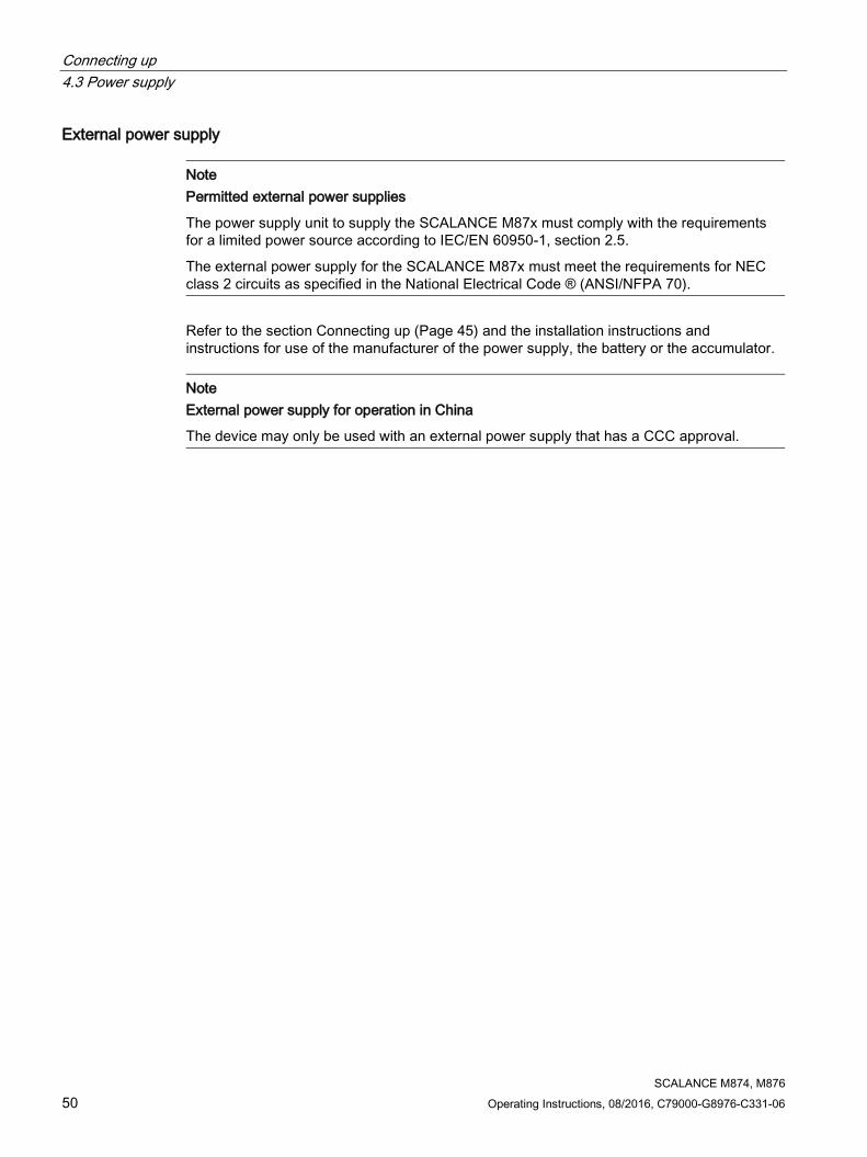
External power supply
Note Permitted external power supplies
The power supply unit to supply the SCALANCE M87x must comply with the requirements for a limited power source according to IEC/EN 60950-1, section 2.5.
The external power supply for the SCALANCE M87x must meet the requirements for NEC class 2 circuits as specified in the National Electrical Code ® (ANSI/NFPA 70).
Refer to the section Connecting up (Page 45) and the installation instructions and instructions for use of the manufacturer of the power supply, the battery or the accumulator.
Note External power supply for operation in China
The device may only be used with an external power supply that has a CCC approval.

Connecting up 4.4 Grounding
SCALANCE M874, M876 Operating Instructions, 08/2016, C79000-G8976-C331-06 51
4.4 Grounding EMC disturbances are diverted to ground via ground. This increases the immunity of the data transmission.
It is crucial for the correct operation of ground that the connection to the reference potential surface always has low impedance. Such a connection of the functional ground of the device does not go first through the cable channel and then to the mounting plate or DIN rail terminal, but goes directly to the mounting plate or DIN rail terminal.
The SCALANCE M87x has a terminal for grounding, refer to the section "Power supply (Page 49)“ or section “Terminals (Page 20)“.
The terminal is identified by the following symbol for the grounding.
1. Connect the terminal of the device with as short a cable as possible ≤ 150 mm and a
large cross-sectional area ≥ 2.5 mm² to the functional ground of the system. In many cases, the entire metallic construction of the system serves as ground.
2. Also connect the standard rails of a system with ground.
Protective earth/functional ground The connection of the reference potential surface with the protective earth system is normally in the cabinet close to the power feed-in. This earth conducts fault currents to ground safely and according to DIN/VDE 0100 is a protective earth to protect people, animals and property from too high contact voltages.
Apart from the protective earth, there is functional grounding in the cabinet. According to EN60204-1 (DIN/VDE 0113 T1) electrical circuits must be grounded. The chassis (0 V) is grounded at one defined point. Here, once again the grounding is implemented with the lowest leakage resistance to ground in the vicinity of the power feed-in.
With automation components, functional ground also ensures interference-free operation of a controller. Via the functional ground, interference currents coupled in via the connecting cables are discharged to ground.
In terms of the large-area and low impedance implementation, a functional ground set up for this purpose generally also meets the requirements of protective earth. On the other hand, protective earth does not always meet the requirements of functional ground. In general while the connection for protective earth is always low resistance, it is not necessarily low impedance.
The resistance of a connection for protective earth must always be as small as possible to divert fault currents safely to ground. The length of a protective earth cable can therefore be several meters (m) long, without seriously impairing this effect. For a functional ground for diverting HF disturbances, this cable does however have impedance and is therefore not suitable.

Connecting up 4.5 Digital input/output
SCALANCE M874, M876 52 Operating Instructions, 08/2016, C79000-G8976-C331-06
4.5 Digital input/output The digital input/output (relay contact) is a floating switch with which error/fault states can be signaled by breaking the contact.
CAUTION
Damage due to voltage being too high or too low
The voltage at the digital input/output must not exceed 30 VDC and not fall below -30 VDC, otherwise the digital input/output will be destroyed.
Note Interference pulse
Zo avoid evaluating an interference pulse, the pulse for the signal 1 (TRUE / HIGH) must be at least 200 ms.
Rules for user wiring
● Always wire the digital input/output in pairs-
● The maximum permitted cable length is 30 m.

Connecting up 4.5 Digital input/output
SCALANCE M874, M876 Operating Instructions, 08/2016, C79000-G8976-C331-06 53
Digital input The 2-pin terminal block has the following assignment:
DI+ 24 VDC DI- (input ground) -
If there is an adequate switching voltage at the digital input, the digital input is active and the "DI" LED is lit.

Connecting up 4.5 Digital input/output
SCALANCE M874, M876 54 Operating Instructions, 08/2016, C79000-G8976-C331-06
Digital output The 2-pin terminal block has the following assignment:
DO+ Relay 24 VDC / 1 A DO- Relay 24 VDC / 1 A

Connecting up 4.6 Antennas
SCALANCE M874, M876 Operating Instructions, 08/2016, C79000-G8976-C331-06 55
4.6 Antennas
Note
Use the antennas from the accessories program for the M87x device. You will find more detailed information in "Accessories (Page 17)". If you use a different antenna, there is no guarantee that the device will function according to the specification.
The antenna socket for connecting the antenna is of the type SMA. The antenna used should have an impedance of about 50 ohms.
CAUTION
Minimum clearance to the device
The device may only be operated when the distance between the device (or antenna) and user is at least 20 cm.
Notes on lightning protection
WARNING
Danger due to lightning strikes
Antennas installed outdoors must be within the area covered by a lightning protection system. Make sure that all conducting systems entering from outdoors are protected by lightning protection electrical bonding.
When implementing your lightning protection concept, make sure you adhere to the requirements of the VDE 0182 or IEC 62305 standards.
Suitable lightning protectors are available in the range of accessories of SIMATIC NET Industrial WLAN:
● Lightning protector LP798-1N (order no. 6GK5798-2LP00-2AA6)
● Lightning protector LP798-2N (order no. 6GK5798-2LP10-2AA6)
Note
We recommend that you use the maintenance-free lightning protector LP798-2N. Exception:
When there is also DC power supplied via the antenna cable. In this case, only the lightning protector LP798-1N can be used.

Connecting up 4.6 Antennas
SCALANCE M874, M876 56 Operating Instructions, 08/2016, C79000-G8976-C331-06
● Depending on the connector, an adapter cable is required to connect to SMA.
WARNING
Danger due to lightning strikes
Installing this lightning protector between an antenna and a SCALANCE M87x is not adequate protection against a lightning strike. The LP798-1N lightening protector only works within the framework of a comprehensive lightning protection concept. If you have questions, ask a qualified specialist company.
Note
The requirements of EN61000-4-5, "Surge Immunity Test" on power supply lines with 24 VDC are met only when a Blitzductor is used:
24 VDC: BVT AVD 24 type no. 918 422
Vendor: DEHN+SÖHNE GmbH+Co.KG, Hans Dehn Str. 1, Postfach 1640, D - 92306 Neumarkt, Germany
Frequency bands in Europe, China, the USA and other regions Depending on the frequency bands used by your mobile wireless provider, antennas must be tuned to the following frequencies:
● In Europe, America, Africa, Asia and Australia:
– GSM 900 MHz
– DCS 1800 MHz
– UMTS 2100 MHz
– LTE 800 MHz, 900 MHz, 1800 MHz, 2100 MHz, 2600 MHz depending on the provider
● In the USA:
– GSM 850 MHz
– PCS 1900 MHz (also for UMTS)
● In Korea:
– UMTS 2100 MHz
Check with your mobile wireless provider for the suitable frequencies.
Signal quality During installation make sure that there is a good signal strength of > -73 dBm.
If the "Q" LED is lit permanently, the signal quality is good. For more detailed information, refer to the section "LED display (Page 22)".
Avoid large metal objects in the immediate vicinity.

Connecting up 4.6 Antennas
SCALANCE M874, M876 Operating Instructions, 08/2016, C79000-G8976-C331-06 57
SCALANCE M876 antenna connectors

Connecting up 4.7 Ethernet port
SCALANCE M874, M876 58 Operating Instructions, 08/2016, C79000-G8976-C331-06
4.7 Ethernet port Connect the local network with the local applications to the Ethernet port, for example a programmable logic controller, a machine with an Ethernet interface for remote monitoring or a PC.
To set up the device, connect a PC with a Web browser to one of the Ethernet ports.
For the connection, use a path cable with an RJ-45 plug. You will find the properties of the Ethernet interface in the technical specifications.

Connecting up 4.8 Inserting and removing the PLUG
SCALANCE M874, M876 Operating Instructions, 08/2016, C79000-G8976-C331-06 59
4.8 Inserting and removing the PLUG
NOTICE
Do not remove or insert a C-PLUG / KEY-PLUG during operation!
A PLUG may only be removed or inserted when the device is turned off. The device checks whether or not a PLUG is present at one second intervals. If it is detected that the PLUG was removed, there is a restart. If a valid KEY-PLUG was inserted in the device, the device changes to a defined error state following the restart. With SCALANCE M, the wireless interface is deactivated in this case.
Inserting the PLUG 1. Turn off the power to the device.
2. The housing of the PLUG has a protruding ridge on the long side. The slot has a groove at this position. Insert the PLUG correctly oriented into the slot.

Connecting up 4.8 Inserting and removing the PLUG
SCALANCE M874, M876 60 Operating Instructions, 08/2016, C79000-G8976-C331-06
Removing the PLUG 1. Turn off the power to the device.
2. Insert a screwdriver between the front edge of the PLUG and the slot and release the PLUG.
3. Remove the PLUG.

SCALANCE M874, M876 Operating Instructions, 08/2016, C79000-G8976-C331-06 61
Dimension drawings 5 5.1 SCALANCE M874-2, M874-3
Dimensions are specified in mm.
Figure 5-1 Side view M874-2 and M874-3

Dimension drawings 5.1 SCALANCE M874-2, M874-3
SCALANCE M874, M876 62 Operating Instructions, 08/2016, C79000-G8976-C331-06
Figure 5-2 Front view M874-2 and M874-3

Dimension drawings 5.2 SCALANCE M876-3, M876-4
SCALANCE M874, M876 Operating Instructions, 08/2016, C79000-G8976-C331-06 63
5.2 SCALANCE M876-3, M876-4 Dimensions are specified in mm.
Figure 5-3 M876-3 and M876-4 side view

Dimension drawings 5.2 SCALANCE M876-3, M876-4
SCALANCE M874, M876 64 Operating Instructions, 08/2016, C79000-G8976-C331-06
Figure 5-4 M876-3 and M876-4 front view

SCALANCE M874, M876 Operating Instructions, 08/2016, C79000-G8976-C331-06 65
Technical specifications 6 6.1 GPRS/EDGE router SCALANCE M874-2
M874-2 Article number 6GK5 874-2AA00-2AA2 Ethernet interface Attachment to Industrial Ethernet
Quantity 2
Design
RJ-45 jack Characteristics: • 10/100BASE-T • Ethernet IEEE 802.3 • 10/100 Mbps
Wireless interface Antenna connector
Quantity 1 Design SMA socket (straight) Impedance 50 Ω nominal Antenna cable Cable length < 30 m
Frequency band GSM 850 MHz = GSM 850 900 MHz = GSM 900 1800 MHz = GSM 1800 1900 MHz = GSM 1900
EGPRS Properties Multislot class 12, end device class B • Coding scheme downlink: CS 1 ... 4, MCS 1
... 9 • Coding scheme uplink: CS 1 ... 4, MCS 1 ... 9
Transmission speed • Downlink: up to 237 kbps: • Uplink: up to 237 kbps:
GPRS Properties Multislot class 12, end device class B, coding scheme 1 … 4
Transmission speed • Downlink: up to 85.6 kbps. • Uplink: up to 85.6 kbps.
GSM (CSD dial-in) Properties Radio Link Protocol (RLP) V.110, non-transparent
Transmission speed up to 14.4 kbps SMS (TX) Properties Text mode, SMSoverIP

Technical specifications 6.1 GPRS/EDGE router SCALANCE M874-2
SCALANCE M874, M876 66 Operating Instructions, 08/2016, C79000-G8976-C331-06
M874-2 Electrical data Power supply Quantity 1
Design Terminal block, 5 terminals Properties Input voltage:
• 12 to 24 VDC • min. 10.8 VDC, max. 28.8 VDC Maximum power consumption 8 W Maximum cable length < 3 m
Digital input Quantity 1 Design Terminal block, 2 terminals Properties Rated voltage 24 VDC Safety Extra Low Voltage
(SELV) For state "1": 10 to 30 VDC For state "0": -30 to 3 VDC Maximum input current 8 mA Cables should be routed in pairs Maximum cable length < 30 m Inputs isolated from electronics.
Digital output Quantity 1 Design Terminal block, 2 terminals Properties Rated voltage 24 VDC Safety Extra Low Voltage
(SELV) Relay, internally not current limited Maximum current carrying capacity 1 A Cables should be routed in pairs Maximum cable length < 30 m Output isolated from electronics
Permitted ambient conditions Ambient temperature During operation -20 ℃ to +60 ℃ During storage -40 ℃ to +70 ℃ During transporta-
tion -40 ℃ to +70 ℃
Relative humidity During operation ≤ 95% at 25 °C, no condensation Design, dimensions and weight Module format Compact module S7-1500 Degree of protection IP20 Weight 290 g Dimensions (W x H x D) 34.8 x 150.9 x 134.7 mm

Technical specifications 6.1 GPRS/EDGE router SCALANCE M874-2
SCALANCE M874, M876 Operating Instructions, 08/2016, C79000-G8976-C331-06 67
M874-2 Installation options • Wall mounting
• Mounting on a DIN rail • Mounting on an S7-300 standard rail • Mounting on an S7-1500 standard rail • Mounting on a pedestal
Installation direction Vertical (ventilation openings at the top and bottom)
Product functions Firewall and security • Stateful inspection
• Packet filter • IPsec VPN for up to 20 connections • Password protection
Router functions • NAPT (port forwarding) • NAT (IP masquerading) • NAT traversal • NETMAP • Dynamic DNS client • DNS cache • NTP • Remote logging • Connection monitoring • Alarm SMS • Sending SMS messages from the local area
network
Configuration / management • Web-based administration user interface (WBM)
• Remote access with HTTPS • SNMP and SNMP traps

Technical specifications 6.2 HSPA+ router SCALANCE M874-3
SCALANCE M874, M876 68 Operating Instructions, 08/2016, C79000-G8976-C331-06
6.2 HSPA+ router SCALANCE M874-3
M874-3 Article number 6GK5 874-3AA00-2AA2 Ethernet interface Attachment to Industrial Ethernet
Quantity 2
Design
RJ-45 jack Characteristics: • 10/100BASE-T • Ethernet IEEE 802.3 • 10/100 Mbps
Wireless interface Antenna connector
Quantity 1 Design SMA socket (straight) Impedance 50 Ω nominal
Antenna cable Cable length < 30 m Frequency bands UMTS 800 MHz = band VI
850 MHz = band V 900 MHz = band VIII 1900 MHz = band II 2100 MHz = band I
GSM 850 MHz = GSM 850 900 MHz = GSM 900 1800 MHz = GSM 1800 1900 MHz = GSM 1900
UMTS with HSPA+ Transmission speed • HSDPA (downlink): up to 14.4 Mbps • HSUPA (uplink): up to 5.76 Mbps
EGPRS Properties Multislot class 12, end device class B • Coding scheme downlink: CS 1 ... 4, MCS 1
... 9 • Coding scheme uplink: CS 1 ... 4, MCS 1 ... 9
Transmission speed • Downlink: up to 237 kbps: • Uplink: up to 237 kbps:
GPRS Properties Multislot class 12, end device class B, coding scheme 1 … 4
Transmission speed • Downlink: up to 85.6 kbps. • Uplink: up to 85.6 kbps.
GSM (CSD dial-in) Properties Radio Link Protocol (RLP) V.110, non-transparent
Transmission speed up to 14.4 kbps

Technical specifications 6.2 HSPA+ router SCALANCE M874-3
SCALANCE M874, M876 Operating Instructions, 08/2016, C79000-G8976-C331-06 69
M874-3 SMS (TX) Properties Text mode, SMSoverIP Electrical data Power supply Quantity 1
Design Terminal block, 5 terminals Properties Input voltage:
• 12 to 24 VDC • min. 10.8 VDC, max. 28.8 VDC Maximum power consumption 8 W Maximum cable length < 3 m
Digital input Quantity 1 Design Terminal block, 2 terminals Properties Rated voltage 24 VDC Safety Extra Low Voltage
(SELV) For state "1": 10 to 30 VDC For state "0": -30 to 3 VDC Maximum input current 8 mA Cables should be routed in pairs Maximum cable length < 30 m Inputs isolated from electronics.
Digital output Quantity 1 Design Terminal block, 2 terminals Properties Rated voltage 24 VDC Safety Extra Low Voltage
(SELV) Relay, internally not current limited Maximum current carrying capacity 1 A Cables should be routed in pairs Maximum cable length < 30 m Output isolated from electronics
Permitted ambient conditions Ambient temperature During operation -20 °C ... +60 °C (vertical installation)
Installed horizontally, the device can be used for ambient temperatures up to 40 °C.
During storage -40 ℃ to +70 ℃ During transporta-
tion -40 ℃ to +70 ℃
Relative humidity During operation ≤ 95% at 25 °C, no condensation Design, dimensions and weight Module format Compact module S7-1500 Degree of protection IP20 Weight 290 g Dimensions (W x H x D) 34.8 x 150.9 x 134.7 mm

Technical specifications 6.2 HSPA+ router SCALANCE M874-3
SCALANCE M874, M876 70 Operating Instructions, 08/2016, C79000-G8976-C331-06
M874-3 Installation options • Wall mounting
• Mounting on a DIN rail • Mounting on an S7-300 standard rail • Mounting on an S7-1500 standard rail • Mounting on a pedestal
Installation direction Vertical (ventilation openings at the top and bottom)
Product functions Firewall and security • Stateful inspection
• Packet filter • IPsec VPN for up to 20 connections • SINEMA RC client • Password protection
Router functions • NAPT (port forwarding) • NAT (IP masquerading) • NAT traversal • NETMAP • Dynamic DNS client • DNS cache • NTP • Remote logging • Connection monitoring
Configuration / management • Web-based administration user interface (WBM)
• Remote access with HTTPS • SNMP and SNMP traps

Technical specifications 6.3 HSPA+ router SCALANCE M876-3
SCALANCE M874, M876 Operating Instructions, 08/2016, C79000-G8976-C331-06 71
6.3 HSPA+ router SCALANCE M876-3
M876-3 Article number 6GK5 876-3AA02-2BA2
6GK5 876-3AA02-2EA2 Ethernet interface Attachment to Industrial Ethernet
Quantity 4
Design
RJ-45 jack Characteristics: • 10/100BASE-T • Ethernet IEEE 802.3 • 10/100 Mbps
Wireless interface Antenna connector
Quantity 2 A1: Main antenna A2: UMTS: RX diversity
Design SMA socket (straight) Impedance 50 Ω nominal Antenna cable Cable length < 30 m
Frequency bands GSM 850 MHz = GSM 850 900 MHz = GSM 900 1800 MHz = GSM 1800 1900 MHz = GSM 1900
UMTS with HSPA+ 800 MHz = band VI 850 MHz = band V 900 MHz = band VIII 1900 MHz = band II 2100 MHz = band I
CDMA 800, 1900 MHz UMTS with HSPA+
Transmission speed • HSDPA (downlink): up to 14.4 Mbps • HSUPA (uplink): up to 5.76 Mbps
CDMA
Properties EV-DO Rev.A Transmission speed • Forward link: up to 3.1 Mbps
• Reverse link: up to 1.8 Mbps
EGPRS Properties Multislot class 12, end device class B • Coding scheme downlink: CS 1 ... 4, MCS 1
... 9 • Coding scheme uplink: CS 1 ... 4, MCS 1 ... 9
Transmission speed • Downlink: up to 237 kbps: • Uplink: up to 237 kbps:

Technical specifications 6.3 HSPA+ router SCALANCE M876-3
SCALANCE M874, M876 72 Operating Instructions, 08/2016, C79000-G8976-C331-06
M876-3 GPRS Properties Multislot class 12, end device class B, coding
scheme 1 … 4 Transmission speed • Downlink: up to 85.6 kbps.
• Uplink: up to 85.6 kbps.
GSM (CSD dial-in) Properties Radio Link Protocol (RLP) V.110, non-transparent
Transmission speed up to 14.4 kbps SMS (TX) Properties Text mode, SMSoverIP Electrical data Power supply Quantity 1
Design Terminal block, 5 terminals Properties Input voltage:
• 12 to 24 VDC • min. 10.8 VDC, max. 28.8 VDC Maximum power consumption 8 W Maximum cable length < 3 m
Digital input Quantity 1 Design Terminal block, 2 terminals Properties Rated voltage 24 VDC Safety Extra Low Voltage
(SELV) For state "1": 10 to 30 VDC For state "0": -30 to 3 VDC Maximum input current 8 mA Cables should be routed in pairs Maximum cable length < 30 m Inputs isolated from electronics.
Digital output Quantity 1 Design Terminal block, 2 terminals Properties Rated voltage 24 VDC Safety Extra Low Voltage
(SELV) Relay, internally not current limited Maximum current carrying capacity 1 A Cables should be routed in pairs Maximum cable length < 30 m Output isolated from electronics
Permitted ambient conditions Ambient temperature During operation Without air flow and with a clearance at the side
of 5 cm to the neighboring device: -20 ℃ to +60 ℃
During storage -40 ℃ to +70 ℃ During transporta-
tion -40 ℃ to +70 ℃
Relative humidity During operation ≤ 95% at 25 °C, no condensation

Technical specifications 6.3 HSPA+ router SCALANCE M876-3
SCALANCE M874, M876 Operating Instructions, 08/2016, C79000-G8976-C331-06 73
M876-3 Design, dimensions and weight Module format Compact module S7-1500 Degree of protection IP20 Weight 290 g Dimensions (W x H x D) 34.8 x 147 x 134.7 mm Installation options • Wall mounting
• Mounting on a DIN rail • Mounting on an S7-300 standard rail • Mounting on an S7-1500 standard rail • Mounting on a pedestal
Installation direction Vertical (ventilation openings at the top and bottom)
Product functions Firewall and security • Stateful inspection
• Packet filter • IPsec VPN for up to 20 connections • SINEMA RC client • Password protection
Router functions • NAPT (port forwarding) • NAT (IP masquerading) • NAT traversal • NETMAP • Dynamic DNS client • DNS cache • NTP • Remote logging • Connection monitoring • Alarm SMS • Sending SMS messages from the local area
network
Configuration / management • Web-based administration user interface (WBM)
• Remote access with HTTPS • SNMP and SNMP traps

Technical specifications 6.4 LTE router SCALANCE M876-4
SCALANCE M874, M876 74 Operating Instructions, 08/2016, C79000-G8976-C331-06
6.4 LTE router SCALANCE M876-4
M876-4 Article number 6GK5 876-4AA00-2BA2 Ethernet interface Attachment to Industrial Ethernet
Quantity 4
Design
RJ-45 jack Characteristics: • 10/100BASE-T • Ethernet IEEE 802.3 • 10/100 Mbps
Wireless interface Antenna connector
Quantity 2 A1: Main antenna A2: UMTS: RX diversity LTE: RX MIMO
Design SMA socket (straight) Impedance 50 Ω nominal Antenna cable Cable length < 30 m
Frequency bands LTE 2100 MHz = band I 1800 MHz = band 3 2600 MHz = band 7 900 MHz = band 8 800 MHz = band 20
UMTS with HSPA+ 900 MHz = band VIII 1800 MHz = band III 2100 MHz = band I
GSM 850 MHz = GSM 850 1900 MHz = GSM 1900
LTE
Transmission speed • Downlink: up to 100 Mbps • Uplink: up to 50 Mbps
UMTS with HSPA+ Transmission speed • HSDPA (downlink): up to 14.4 Mbps • HSUPA (uplink): up to 5.76 Mbps
EGPRS Properties Multislot class 12, end device class B • Coding scheme downlink: CS 1 ... 4, MCS 1
... 9 • Coding scheme uplink: CS 1 ... 4, MCS 1 ... 9
Transmission speed • Downlink: up to 237 kbps: • Uplink: up to 237 kbps:

Technical specifications 6.4 LTE router SCALANCE M876-4
SCALANCE M874, M876 Operating Instructions, 08/2016, C79000-G8976-C331-06 75
M876-4 GPRS Properties Multislot class 12, end device class B, coding
scheme 1 … 4 Transmission speed • Downlink: up to 85.6 kbps.
• Uplink: up to 85.6 kbps.
GSM (CSD dial-in) Properties Radio Link Protocol (RLP) V.110, non-transparent
Transmission speed up to 14.4 kbps SMS (TX) Properties Text mode, SMSoverIP Electrical data Power supply Quantity 1
Design Terminal block, 5 terminals Properties Input voltage:
• 12 to 24 VDC • min. 10.8 VDC, max. 28.8 VDC Maximum power consumption 8 W Maximum cable length < 3 m
Digital input Quantity 1 Design Terminal block, 2 terminals Properties Rated voltage 24 VDC Safety Extra Low Voltage
(SELV) For state "1": 10 to 30 VDC For state "0": -30 to 3 VDC Maximum input current 8 mA Cables should be routed in pairs Maximum cable length < 30 m Inputs isolated from electronics.
Digital output Quantity 1 Design Terminal block, 2 terminals Properties Rated voltage 24 VDC Safety Extra Low Voltage
(SELV) Relay, internally not current limited Maximum current carrying capacity 1 A Cables should be routed in pairs Maximum cable length < 30 m Output isolated from electronics

Technical specifications 6.4 LTE router SCALANCE M876-4
SCALANCE M874, M876 76 Operating Instructions, 08/2016, C79000-G8976-C331-06
M876-4 Permitted ambient conditions Ambient temperature During operation Without air flow and with a clearance at the side
of 5 cm to the neighboring device: -20 ℃ to +60 ℃ Without clearance at the side and an air flow of 0.5 m/s (Only in the “LTE only” mode) -20 ℃ to +70 ℃
During storage -40 ℃ to +70 ℃ During transporta-
tion -40 ℃ to +70 ℃
Relative humidity During operation ≤ 95% at 25 °C, no condensation Design, dimensions and weight Module format Compact module S7-1500 Degree of protection IP20 Weight 290 g Dimensions (W x H x D) 34.8 x 147 x 134.7 mm Installation options • Installation in a 19" rack
• Mounting on a DIN rail • Mounting on an S7-300 standard rail • Mounting on an S7-1500 standard rail • Wall mounting • Mounting on a pedestal
Installation direction Vertical (ventilation openings at the top and bottom)

Technical specifications 6.4 LTE router SCALANCE M876-4
SCALANCE M874, M876 Operating Instructions, 08/2016, C79000-G8976-C331-06 77
M876-4 Product functions Firewall and security • Stateful inspection
• Packet filter • IPsec VPN for up to 20 connections • SINEMA RC client • Password protection
Router functions • NAPT (port forwarding) • NAT (IP masquerading) • NAT traversal • NETMAP • Dynamic DNS client • DNS cache • NTP • Remote logging • Connection monitoring • Alarm SMS • Sending SMS messages from the local area
network
Configuration / management • Web-based administration user interface (WBM)
• Command Line Interface (CLI) • Remote access with HTTPS • SNMP and SNMP traps

Technical specifications 6.5 LTE router SCALANCE M876-4 (NAM)
SCALANCE M874, M876 78 Operating Instructions, 08/2016, C79000-G8976-C331-06
6.5 LTE router SCALANCE M876-4 (NAM)
M876-4 (NAM) Article number 6GK5876-4AA00-2DA2 Ethernet interface Attachment to Industrial Ethernet
Quantity 4
Design
RJ-45 jack Characteristics: • 10/100BASE-T • Ethernet IEEE 802.3 • 10/100 Mbps
Wireless interface Antenna connector
Quantity 2 A1: Main antenna A2: UMTS: RX diversity LTE: RX MIMO
Design SMA socket (straight) Impedance 50 Ω nominal Antenna cable Cable length < 30 m
Frequency bands LTE 1900 MHz = band 2 AWS = band 4 850 MHz = band 5 700 MHz = band 17 700 MHz = band 13
UMTS with HSPA+ 850 MHz = band V AWS = band IV 1900 MHz = band II
GSM 850 MHz = GSM 850 900 MHz = GSM 900 1800 MHz = GSM 1800 1900 MHz = GSM 1900
LTE
Transmission speed • Downlink: up to 100 Mbps • Uplink: up to 50 Mbps
UMTS with HSPA+ Transmission speed • HSDPA (downlink): up to 14.4 Mbps • HSUPA (uplink): up to 5.76 Mbps
EGPRS Properties Multislot class 12, end device class B • Coding scheme downlink: CS 1 ... 4, MCS 1
... 9 • Coding scheme uplink: CS 1 ... 4, MCS 1 ... 9

Technical specifications 6.5 LTE router SCALANCE M876-4 (NAM)
SCALANCE M874, M876 Operating Instructions, 08/2016, C79000-G8976-C331-06 79
M876-4 (NAM) Transmission speed • Downlink: up to 237 kbps:
• Uplink: up to 237 kbps:
GPRS Properties Multislot class 12, end device class B, coding scheme 1 … 4
Transmission speed • Downlink: up to 85.6 kbps. • Uplink: up to 85.6 kbps.
GSM (CSD dial-in) Properties Radio Link Protocol (RLP) V.110, non-transparent
Transmission speed up to 14.4 kbps SMS (TX) Properties Text mode, SMSoverIP Electrical data Power supply Quantity 1
Design Terminal block, 5 terminals Properties Input voltage:
• 12 to 24 VDC • min. 10.8 VDC, max. 28.8 VDC Maximum power consumption 8 W Maximum cable length < 3 m
Digital input Quantity 1 Design Terminal block, 2 terminals Properties Rated voltage 24 VDC Safety Extra Low Voltage
(SELV) For state "1": 10 to 30 VDC For state "0": -30 to 3 VDC Maximum input current 8 mA Cables should be routed in pairs Maximum cable length < 30 m Inputs isolated from electronics.
Digital output Quantity 1 Design Terminal block, 2 terminals Properties Rated voltage 24 VDC Safety Extra Low Voltage
(SELV) Relay, internally not current limited Maximum current carrying capacity 1 A Cables should be routed in pairs Maximum cable length < 30 m Output isolated from electronics

Technical specifications 6.5 LTE router SCALANCE M876-4 (NAM)
SCALANCE M874, M876 80 Operating Instructions, 08/2016, C79000-G8976-C331-06
M876-4 (NAM) Permitted ambient conditions Ambient temperature During operation Without air flow and with a clearance at the side
of 5 cm to the neighboring device: -20 ℃ to +60 ℃ Without clearance at the side and an air flow of 0.5 m/s (Only in the “LTE only” mode) -20 ℃ to +70 ℃
During storage -40 ℃ to +70 ℃ During transporta-
tion -40 ℃ to +70 ℃
Relative humidity During operation ≤ 95% at 25 °C, no condensation Design, dimensions and weight Module format Compact module S7-1500 Degree of protection IP20 Weight 290 g Dimensions (W x H x D) 34.8 x 147 x 134.7 mm Installation options • Installation in a 19" rack
• Mounting on a DIN rail • Mounting on an S7-300 standard rail • Mounting on an S7-1500 standard rail • Wall mounting • Mounting on a pedestal
Installation direction Vertical (ventilation openings at the top and bottom)

Technical specifications 6.5 LTE router SCALANCE M876-4 (NAM)
SCALANCE M874, M876 Operating Instructions, 08/2016, C79000-G8976-C331-06 81
M876-4 (NAM) Product functions Firewall and security • Stateful inspection
• Packet filter • IPsec VPN for up to 20 connections • SINEMA RC client • Password protection
Router functions • NAPT (port forwarding) • NAT (IP masquerading) • NAT traversal • NETMAP • Dynamic DNS client • DNS cache • NTP • Remote logging • Connection monitoring • Alarm SMS • Sending SMS messages from the local area
network
Configuration / management • Web-based administration user interface (WBM)
• Command Line Interface (CLI) • Remote access with HTTPS • SNMP and SNMP traps

Technical specifications 6.6 Antenna gain
SCALANCE M874, M876 82 Operating Instructions, 08/2016, C79000-G8976-C331-06
6.6 Antenna gain
Antenna gain for M874-2, M87x-3 Users and installers must be provided with antenna installation instructions and transmitter operating conditions that must be followed to avoid exceeding the permitted RF exposure. Maximum antenna gain
GSM 1800 GSM 900 SCALANCE M874-2 10.04 dBi 4.05 dBi SCALANCE M874-3 9.36 dBi 2.91 dBi SCALANCE M876-3 9.36 dBi 2.91 dBi
Antenna gain for M876-4
Note
Depending on the selected wireless standard and the wireless frequency used, antennas with different antenna gains can be used. If you change the frequency band during operation, it is possible that the maximum permitted antenna again also changes. Check whether the antenna you are using is approved for the changed frequency range. If necessary, change the antenna so as not to violate the operational requirements. Or use an antenna with a gain less than 3.58 dBi to cover all bands.
Frequency band Maximum antenna gain in dBi GSM /GPRS 900 3.58 E-GPRS 900 9.88 GSM /GPRS 1800 9.84 E-GPRS 1800 13.85 UMTS FDD1 13.35 UMTS FDD III 13.45 UMTS VIII 10.27 LTE FDD 3 12.66 LTE FDD 7 13.86 LTE FDD 8 10.58 LTE FDD 20 8.76

Technical specifications 6.6 Antenna gain
SCALANCE M874, M876 Operating Instructions, 08/2016, C79000-G8976-C331-06 83
Antenna gain for M876-4NAM
R&TTE / RED (Europe) Frequency band Maximum antenna gain in dBi 900 MHz GSM /GPRS 900 2.96
GSM /GPRS 1800 8.85
FFC (USA) Frequency band Maximum antenna gain in
dBi 850 MHz LTE 850 MHz = band 5 3.25
700 MHz = band 17 3.25 GSM 850 MHz = GSM 850 3.25 UMTS with HSPA+
850 MHz = band V 3.25
1700 MHz LTE AWS = band 4 5.5 UMTS with HSPA+
AWS = band IV 5.5
1900 MHz LTE 1900 MHz = band 2 2.51 GSM 1900 MHz = GSM 1900 2.51 UMTS with HSPA+
1900 MHz = band II 2.51
IC (Canada) Frequency band Maximum antenna gain in dBi 850 MHz LTE 850 MHz = band 5 0.16
700 MHz = band 13 0.16 700 MHz = band 17 0.16
GSM 850 MHz = GSM 850 0.16 UMTS with HSPA+ 850 MHz = band V 0.16 1700 MHz LTE AWS = band 4 5.5 UMTS with HSPA+ AWS = band IV 5.5 1900 MHz LTE 1900 MHz = band 2 2.51 GSM 1900 MHz = GSM 1900 2.51 UMTS with HSPA+ 1900 MHz = band II 2.51

Technical specifications 6.6 Antenna gain
SCALANCE M874, M876 84 Operating Instructions, 08/2016, C79000-G8976-C331-06

SCALANCE M874, M876 Operating Instructions, 08/2016, C79000-G8976-C331-06 85
Approvals A
Approvals issued
Note Issued approvals on the type plate of the device
The specified approvals apply only when the corresponding mark is printed on the product. You can check which of the following approvals have been granted for your product by the markings on the type plate.
Approvals for shipbuilding are not printed on the device type plate.
WARNING
Personal injury and property damage can occur
The installation of expansions that are not approved for SIMATIC NET products or their target systems may violate the requirements and regulations for safety and electromagnetic compatibility.
Only use expansions that are approved for the system.

Approvals
SCALANCE M874, M876 86 Operating Instructions, 08/2016, C79000-G8976-C331-06
● Keep to the installation guidelines The devices meet the requirements if you adhere to the installation and safety instructions contained in this documentation and in the following documentation when installing and operating the devices.
● You can always find the latest documentation on the Internet The current descriptions of the currently available products can always be found on the Internet under the specified entry IDs/Internet pages:
– "Industrial Ethernet / PROFINET Industrial Ethernet" System Manual
– "Industrial Ethernet / PROFINET - Passive network components" System Manual
You will find information on the system manuals in the section "Preface (Page 3)", in "Further documentation".
– "EMC Installation Guidelines" configuration manual
ID = 60612658 (http://support.automation.siemens.com/WW/view/en/60612658)
● Working on the device To protect the device from electrostatic discharge, personnel must first discharge any electrostatic charge from their body before touching the device.
Note
The test was performed with a device and a connected communications partner that also meets the requirements of the standards listed above.
When operating the device with a communications partner that does not comply with these standards, adherence to the corresponding values cannot be guaranteed.
Current approvals on the Internet You will find the current approvals for the product on the Internet pages of Siemens Industry Online Support.
80046561 (http://support.automation.siemens.com/WW/view/en/80046561/134200)
National approvals You will find an overview of the country-specific wireless approvals of SIMATIC NET devices with GSM or UMTS services on the Internet pages of Siemens Automation Customer Support. You will find the link to the document on the following page:
ik-Info (www.siemens.com/simatic-net/ik-info)

Approvals A.1 EU declaration of conformity
SCALANCE M874, M876 Operating Instructions, 08/2016, C79000-G8976-C331-06 87
A.1 EU declaration of conformity
The EC Declaration of Conformity is available for all responsible authorities at:
Siemens Aktiengesellschaft Process Industries and Drives Division, Process Automation DE-76181 Karlsruhe Germany
You will find the EC declaration of conformity for these products on the Internet pages of Siemens Industry Online Support (https://support.industry.siemens.com/cs/ww/en/ps/15914/cert).
The SIMATIC NET products described in these Operating Instructions meet the requirements of the following EC directives:
● 94/9/EC
Directive of the European Parliament and the Council of 23 March 1994 on the approximation of the laws of the Member States concerning equipment and protective systems intended for use in potentially explosive atmospheres (until 19.04.2016).
● 2014/34/EU
Directive of the European Parliament and of the Council of 26 February 2014 on the harmonization of the laws of the Member States relating to equipment and protective systems intended for use in potentially explosive atmospheres official journal of the EU L96, 29/03/2014, pages. 309–356 (as of 20.04.2016)
● 1999/5/EC
Directive of the European Parliament and of the Council of March 9, 1999 on Radio Equipment and Telecommunications Terminal Equipment and the mutual recognition of their conformity (until 12.06.2016).
● 2014/53/EU
Directive of the European Parliament and of the Council of April 16, 2014 on the harmonization of the laws of the member states relating to placing radio equipment on the market.; official journal of the EU L153, 22/05/2014, pages. 62–106 (as of 13.06.2016)
● 2011/65/EU (RoHS)
RoHS directive of the European Parliament and of the Council of 8 June 2011 on the restriction of the use of certain hazardous substances in electrical and electronic equipment.
The current versions of the applied standards can be seen in the EC Declaration of Conformity.
Which of the described standards apply to the product can be found in Products (Page 90).

Approvals A.1 EU declaration of conformity
SCALANCE M874, M876 88 Operating Instructions, 08/2016, C79000-G8976-C331-06
A.1.1 ATEX
ATEX directive (correct usage in potentially explosive atmospheres) The SIMATIC NET product meets the requirements of the EC directive:94/9/EC (until 19.04.2016) and 2014/34/EU (as of 20.04.2016) "Equipment and Protective Devices for Use in Potentially Explosive Atmospheres" according to the standards listed in the section Products (Page 90):
Applied standard:
1 EN 60079-0 Hazardous areas - Part 0: Equipment - General requirements
2 EN 60079-15 Explosive atmospheres - Part 15: Equipment protection by type of protection "n"
A.1.2 RoHS
RoHS directive (restriction of the use of certain hazardous substances) The SIMATIC NET products described in these operating instructions meet the requirements of the EC directive 2011/65/EC for the restriction of the use of certain hazardous substances in electrical and electronic equipment:
Applied standard:
3 EN 50581 Technical documentation for the assessment electrical and electronic products with respect to restriction of hazardous substances
A.1.3 R&TTE / RED
A.1.3.1 Protection of health and safety Article 3 (1) a) protection of health and safety
4 EN 60950-1 Information technology equipment - Safety - Part 1: General requirements
5 EN 62311 Assessment of electronic and electrical equipment related to human exposure re-strictions for electromagnetic fields (0 Hz – 300 GHz)

Approvals A.1 EU declaration of conformity
SCALANCE M874, M876 Operating Instructions, 08/2016, C79000-G8976-C331-06 89
Art. 3 (1) b) EMC
6 ETSI EN 301 489-1 Electromagnetic compatibility and radio spectrum matters (ERM) - Electromagnetic compatibility for radio equipment and services - Part 1 : Common technical re-quirements
7 ETSI EN 301 489-7 Electromagnetic compatibility and radio spectrum matters (ERM) - Electromagnetic compatibility for radio equipment and services - Part 7 : Specific conditions for mobile and portable radio and ancillary equipment of digital cellular radio telecom-munications systems (GSM and DCS).
8 ETSI EN 301 489-24 Electromagnetic compatibility and radio spectrum matters (ERM) - Electromagnetic compatibility for radio equipment and services - Part 24 : Specific conditions for mobile and portable IMT-2000 CDMA Direct Spread (UTRA) radio and ancillary equipment.
9 EN 61000-6-2 Electromagnetic compatibility (EMC) - Part 6-2: Generic standards - Immunity for industrial environments
10 EN 61000-6-3 Electromagnetic compatibility (EMC) - Part 6-3: Generic standards - Emission standard for residential, commercial and light-industrial environments
11 EN 61000-6-4 Electromagnetic compatibility (EMC) - Part 6-4: Generic standards - Emission standard for industrial environments
Art. 3 (2) Efficient use of the radio spectrum
12 ETSI EN 301 511 Global System for Mobile communications (GSM); Harmonized EN for mobile sta-tions in the GSM 900 and GSM 1800 bands covering essential requirements of article 3.2 of the R&TTE directive
13 ETSI EN 301 908-1 IMT cellular networks - Harmonized EN covering the essential requirements of arti-cle 3.2 of the R&TTE directive - Part 1: Introduction and common requirements
14 ETSI EN 301 908-2 IMT cellular networks - Harmonized EN covering the essential requirements of arti-cle 3.2 of the R&TTE directive - Part 2: CDMA Direct Spread (UTRA FDD) User Equipment (UE)
15 ETSI EN 301 908-13 IMT cellular networks - Harmonized EN covering the essential requirements of article 3.2 of the R&TTE directive - Part 13: Further developed universal terrestrial wireless access (E-UTRA) end devices (UE)

Approvals A.1 EU declaration of conformity
SCALANCE M874, M876 90 Operating Instructions, 08/2016, C79000-G8976-C331-06
A.1.4 Products
Product designation and standards
The standards that apply to the product are described in ATEX (Page 88), RoHS (Page 88) and R&TTE / RED (Page 88). Product name Standards SCALANCE M874-2 1, 2, 3, 4, 5, 6, 9, 10, 11, 12 SCALANCE M874-3 1, 2, 3, 4, 5, 6, 7, 9, 11, 12, 13, 14 SCALANCE M876-3 1, 2, 3, 4, 5, 6, 7, 9, 11, 12, 13, 14 SCALANCE M876-4 1, 2, 3, 4, 5, 6, 7, 8, 9, 11, 12, 13, 14, 15
See also Antenna gain (Page 82)

Approvals A.2 RCM / C-TICK
SCALANCE M874, M876 Operating Instructions, 08/2016, C79000-G8976-C331-06 91
A.2 RCM / C-TICK The products meet the requirements of the AS/NZS CISPR11 : 2011 standard (Industrial, scientific and medical equipment - Radio- frequency disturbance characteristics - Limits and methods of measurement).

Approvals A.3 ATEX
SCALANCE M874, M876 92 Operating Instructions, 08/2016, C79000-G8976-C331-06
A.3 ATEX
Explosion protection directive (ATEX) The SIMATIC NET product meets the requirements of the EC directives:94/9/EC (until 19.04.2016) and 2014/34/EU (as of 20.04.2016) "Equipment and Protective Devices for Use in Potentially Explosive Atmospheres”.
WARNING
When using (installing) SIMATIC NET products in hazardous area zone 2, make absolutely sure that the associated conditions are adhered to:
You will find these conditions in the document (DC_ATEX_99.pdf) "Approval of SIMATIC/ SIMATIC NET Products for Direct Installation in Ex-Zone 2"
You will find the document on the accompanying product CD and in the SIMATIC NET Manual Collection.
ATEX code:
II 3 G Ex nA IIC T4 Gc
Name, address of the notified center:
DEKRA CERTIFICATION B.V., Utrechtseweg 310, 6812 AR Arnhem, P.O. Box 5185, 6802 ED Arnhem,
The Netherlands
Test type certificate
KEMA 07 ATEX 0145X
The product meets the requirements of the standards
● EN 60079-0: Explosive atmospheres - Part 0: Equipment - General requirements
● EN 60079-15: Explosive atmospheres - Part 15: Equipment protection by type of protection "n"
The current versions of the standards can be seen in the current version of the type examination certificate KEMA 07 ATEX 0145 X.

Approvals A.4 IECEx
SCALANCE M874, M876 Operating Instructions, 08/2016, C79000-G8976-C331-06 93
A.4 IECEx
IECEx The SIMATIC NET products meet the requirements of explosion protection according to IECEx.
IECEx classification:
Ex nA IIC T4 Gc
DEK 14.0025X
The products meet the requirements of the following standards:
● IEC 60079-0 : Explosive atmospheres - Part 0: Equipment - General requirements
● IEC 60079-15 : Explosive atmospheres - Part 15: Equipment protection by type of protection "n"
The current versions of the standards can be seen in the current version of the IECEx certificate DEK 14.0025X.
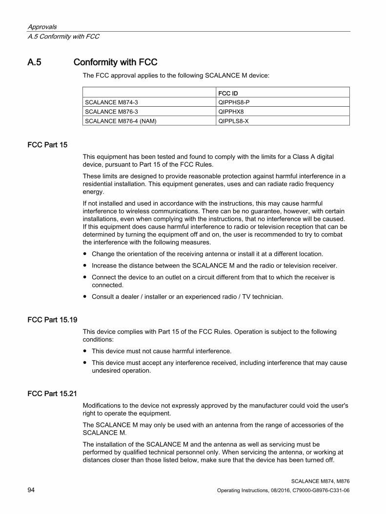
Approvals A.5 Conformity with FCC
SCALANCE M874, M876 94 Operating Instructions, 08/2016, C79000-G8976-C331-06
A.5 Conformity with FCC The FCC approval applies to the following SCALANCE M device: FCC ID SCALANCE M874-3 QIPPHS8-P SCALANCE M876-3 QIPPHX8 SCALANCE M876-4 (NAM) QIPPLS8-X
FCC Part 15 This equipment has been tested and found to comply with the limits for a Class A digital device, pursuant to Part 15 of the FCC Rules.
These limits are designed to provide reasonable protection against harmful interference in a residential installation. This equipment generates, uses and can radiate radio frequency energy.
If not installed and used in accordance with the instructions, this may cause harmful interference to wireless communications. There can be no guarantee, however, with certain installations, even when complying with the instructions, that no interference will be caused. If this equipment does cause harmful interference to radio or television reception that can be determined by turning the equipment off and on, the user is recommended to try to combat the interference with the following measures.
● Change the orientation of the receiving antenna or install it at a different location.
● Increase the distance between the SCALANCE M and the radio or television receiver.
● Connect the device to an outlet on a circuit different from that to which the receiver is connected.
● Consult a dealer / installer or an experienced radio / TV technician.
FCC Part 15.19 This device complies with Part 15 of the FCC Rules. Operation is subject to the following conditions:
● This device must not cause harmful interference.
● This device must accept any interference received, including interference that may cause undesired operation.
FCC Part 15.21 Modifications to the device not expressly approved by the manufacturer could void the user's right to operate the equipment.
The SCALANCE M may only be used with an antenna from the range of accessories of the SCALANCE M.
The installation of the SCALANCE M and the antenna as well as servicing must be performed by qualified technical personnel only. When servicing the antenna, or working at distances closer than those listed below, make sure that the device has been turned off.

Approvals A.5 Conformity with FCC
SCALANCE M874, M876 Operating Instructions, 08/2016, C79000-G8976-C331-06 95
This device contains GSM, GPRS Class 12, EGPRS Class 10, and UMTS functions in the 900 and 1800 MHz band that must not be used in territories of the USA.
This device can be used for mobile and fixed applications. Internal / external antennas used with this device must be at a distance of at least 20 cm from all persons and must not be located so that they operate in combination with any other antenna or transmitter.
Users and installers must be provided with antenna installation instructions and transmitter operating conditions that must be followed to avoid exceeding the permitted RF exposure.
Antennas for the transmitter module used must not exceed the following antenna gains in operating configurations for mobile and fixed applications, see Maximum antenna gain (Page 90).
This device is approved as a module for installation in other devices.
See also Antenna gain (Page 82)

Approvals A.6 RSS-210 Industry of Canada
SCALANCE M874, M876 96 Operating Instructions, 08/2016, C79000-G8976-C331-06
A.6 RSS-210 Industry of Canada
RSS-247 of Industry Canada for SCALANCE M876-4 (NAM) This device complies with Industry Canada licence-exempt RSS standard(s).
Operation is subject to the following two conditions: (1) this device may not cause interference, and (2) this device must accept any interference, including interference that may cause undesired operation of the device.
This radio transmitter (IC: 267AA-MPCIE1V1) has been approved by Industry Canada to operate with the antenna types listed in section 5.4 with the maximum permissible gain and required antenna impedance for each antenna type indicated. Antenna types not included in this list, having a gain greater than the maximum gain indicated for that type, are strictly prohibited for use with this device.
Under Industry Canada regulations, this radio transmitter may only operate using an antenna of a type and maximum (or lesser) gain approved for the transmitter by Industry Canada. To reduce potential radio interference to other users, the antenna type and its gain should be so chosen that the equivalent isotropically radiated power (e.i.r.p.) is not more than that necessary for successful communication.
To reduce potential radio interference to other users, the antenna type and its gain should be so chosen that the equivalent isotropically radiated power (e.i.r.p.) is not more than that permitted for successful communication.
That the device for the band 5150-5250 MHz is only for indoor usage to reduce potential for harmful interference to co-channel mobile satellite systems.
Users should also be cautioned to take note that high power radars are allocated as primary users (meaning they have priority) of 5250-5350 MHz and 5650-5850 MHz and these radars could cause interference and/or damage to LE-LAN devices.
This equipment complies with IC RSS-102 radiation exposure limits set forth for an uncontrolled environment. This equipment should be installed and operated with minimum distance 20cm between the radiator & your body.
Le présent appareil est conforme aux CNR d'Industrie Canada applicables aux appareils radio exempts de licence. L'exploitation est autorisée aux deux conditions suivantes : (1) l'appareil ne doit pas produire de brouillage, et (2) l'utilisateur de l'appareil doit accepter tout brouillage radioélectrique subi, même si le brouillage est susceptible d'en compromettre le fonctionnement.
See also Antenna gain (Page 82)

Approvals A.7 FM certification
SCALANCE M874, M876 Operating Instructions, 08/2016, C79000-G8976-C331-06 97
A.7 FM certification
Approved for use in Cl. 1, Div. 2, GP. A, B, C, D, T4 Cl. 1, Zone 2, GP. IIC T4
Ta: -20 °C to + 60 C
For the use of the product in hazardous areas, the following requirements are met:
● Factory Mutual Approval Standard Class Number 3611
● FM Hazardous (Classified) Location Electrical Equipment: Non Incendive / Class I / Division 2 / Groups A,B,C,D / T4 and Non Incendive / Class I / Zone 2 / Group IIC / T4

Approvals A.8 UL certification (product safety)
SCALANCE M874, M876 98 Operating Instructions, 08/2016, C79000-G8976-C331-06
A.8 UL certification (product safety)
Applied standards
● UL 60950-1 (Information Technology Equipment)
● UL 508 (Industrial Control Equipment)
● CSA C22.2 No.60950-1 (Information Technology Equipment)

Approvals A.9 UL HAZ. LOC certification (explosion protection)
SCALANCE M874, M876 Operating Instructions, 08/2016, C79000-G8976-C331-06 99
A.9 UL HAZ. LOC certification (explosion protection)
I.T.E. for HAZ.LOC.
CL.I, DIV.2, GP A,B,C,D T4
CL.1, Zone2, GP IIC, T4
For temperature information "T.." or the maximum ambient temperature "Ta:..", refer to the type plate.
Applied standards
● UL 60950-1 (Information Technology Equipment)
● CSA C22.2 No.60950-1 (Information Technology Equipment)
● ANSI/ISA 12.12.01-2007
● CSA C22.2 No. 213-M1987

Approvals A.10 EAC
SCALANCE M874, M876 100 Operating Instructions, 08/2016, C79000-G8976-C331-06
A.10 EAC
Marking for the customs union EAC (Eurasian Conformity)
Customs union of Russia, Belarus and Kazakhstan
Declaration of the conformity according to the technical regulations of the customs union (TR CU)

SCALANCE M874, M876 Operating Instructions, 08/2016, C79000-G8976-C331-06 101
Index
A Accessories, 17
C Connecting up
Digital input, 53 Digital output, 54 Ethernet interface, 58 Grounding, 51 Power supply, 49 SIM card, 48
C-PLUG, 29
D Digital input, 53 Digital output, 54 Dimension drawing
SCALANCE M874-2, 61 SCALANCE M874-3, 61 SCALANCE M876-3, 63 SCALANCE M876-4, 63
DIN rail, 36
E Ethernet interface, 58 External power supply
China, 50
G Glossary, 5 Grounding, 51
I Installation
DIN rail, 36 Pedestal, 42 S7-1500 standard rail, 40, 40
S7-300 standard rail, 38 Wall, 34
K KEY-PLUG, 29
L LED display
M874-2, 22 M874-3, 22 M876-3, 25
P Power supply, 49 Product property, 15
S S7-1500 standard rail, 40 S7-300 standard rail, 38 Safety notices
for installation, 31 Use in hazardous areas, 31, 46 when connecting up, 46
Scope of delivery, 15 SET button, 27 Signal quality, 56 SIM card, 48 SIMATIC NET glossary, 5 System manual, 86
W Wall mounting, 34

Index
SCALANCE M874, M876 102 Operating Instructions, 08/2016, C79000-G8976-C331-06