1. 2 overview shared ethernet works extremely well under ideal conditions. when the number of...
TRANSCRIPT

1

2
OverviewShared Ethernet works extremely well under ideal conditions.
When the number of devices trying to access the network is low, the number of collisions stays well within acceptable limits.
However, when the number of users on the network increases, the increased number of collisions can cause intolerable performance.
Bridging was developed to help ease performance problems that arose from increased collisions.
Switching evolved from bridging to become the key technology in modern Ethernet LANs.

3
Layer 2 BridgingAs more nodes are added to an Ethernet physical segment, contention for the media increases.
Ethernet is a shared media, which means only one node can transmit data at a time.
The addition of more nodes increases the demands on the available bandwidth and places additional loads on the media.
By increasing the number of nodes on a single segment, the probability of collisions increases, resulting in more and more retransmissions.
A solution to the problem is to break the large segment into smaller parts and separate them into isolated collision domains.
To accomplish this a bridge keeps a table of MAC addresses and the associated ports in its memory.
The bridge then forwards or discards frames based on the table entries.

4
Bridging Graphic

5
Layer 2 SwitchingGenerally, a bridge has only two ports limiting the division into two collision domains.
All decisions made by a bridge are based on MAC or Layer 2 addressing and do not affect the logical or Layer 3 addressing. Thus, a bridge will divide a collision domain but has no effect on a logical or broadcast domain.
On the other hand a switch is essentially a fast, multi-port bridge, which can contain dozens of ports.
Rather than accommodate only two collision domains, each port creates its own collision domain.
In a network of twenty nodes, twenty collision domains exist if each node is plugged into its own switch port.
If an uplink port is included, one switch can accomodate twenty-one single-node collision domains.
A switch dynamically builds and maintains a Content-Addressable Memory (CAM) table, holding all of the necessary MAC information for each port.

6
MicrosegmentationA switch is simply a bridge with many ports. The two nodes in this small segment, or collision domain, consist of the two switch ports and the host connected to each. These small physical segments are called microsegments.

7
Full DuplexAnother capability emerges when only two nodes are connected. In a network that uses twisted-pair cabling, one pair is used to carry the transmitted signal from one node to the other node. A separate pair is used for the return or received signal. The capability of communication in both directions at the same time is known as full duplex.

8
LatencyLatency is the delay measured between the time a frame first starts to leave the source device and the time the first part of the frame reaches its destination.
A wide variety of conditions can cause delay as a frame travels from source to destination:
• Media delays caused by the finite speed that signals can travelthrough the physical media.
• Circuit delays caused by the electronics that process the signalalong the path.
• Software delays caused by the decisions that software must maketo implement switching and protocols.
• Delays caused by the content of the frame and influenced by the frame switching decisions to be made. For example, a device
cannot route a frame to a destination until the destination MAC address has been read
9
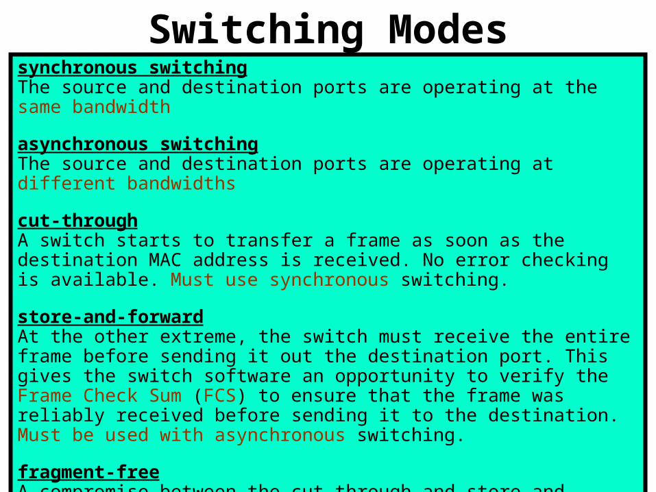
Switching Modessynchronous switchingThe source and destination ports are operating at the same bandwidth
asynchronous switchingThe source and destination ports are operating at different bandwidths
cut-throughA switch starts to transfer a frame as soon as the destination MAC address is received. No error checking is available. Must use synchronous switching.
store-and-forwardAt the other extreme, the switch must receive the entire frame before sending it out the destination port. This gives the switch software an opportunity to verify the Frame Check Sum (FCS) to ensure that the frame was reliably received before sending it to the destination. Must be used with asynchronous switching.
fragment-freeA compromise between the cut-through and store-and-forward modes.Fragment-free reads the first 64 bytes, which includes the frame header, and switching begins before the entire data field and checksum are read.

10
Spanning Tree Protocol (STP)Allows switches to be set up with redundant links, while preventing switching loops. Each switch in a LAN using STP sends special messages called Bridge Protocol Data Units (BPDUs) out all its ports to let other switches know of its existence and to elect a root bridge for the network. The switches then use the Spanning-Tree Algorithm (STA) to resolve and shut down the redundant paths.

11
The 5 STP States
Mr. J. Schram Mnemonic to remember the 5 STP states:
BettyLikesLeaningFeatherDusters
Remember…Do not confuse Shielded Twisted Pair (STP) with Spanning Tree Protocol (STP)

12
Directly Connected EnvironmentsShared media environmentOccurs when multiple hosts have access to the same medium.
Extended shared media environmentIs a special type of shared media environment in which networking devices can extend the environment so that it can accommodate multiple access on longer cable distances.
Point-to-point network environmentIs widely used in dialup network connections and is the most familiar to the home user. It is a shared networking environment in which one device is connected to only one other device, such as connecting a computer to an Internet Service Provider (ISP) by modem and a phone line.

13
Indirectly Connected Environments
Circuit SwitchedAll packets take the same route. All packets arrive at the destination in order.
Packet SwitchedEach packet takes it own route. Allows multiple packets to be sent simultaneously over different paths.Packets usually arrive out of order and must be sorted at the destination.
14
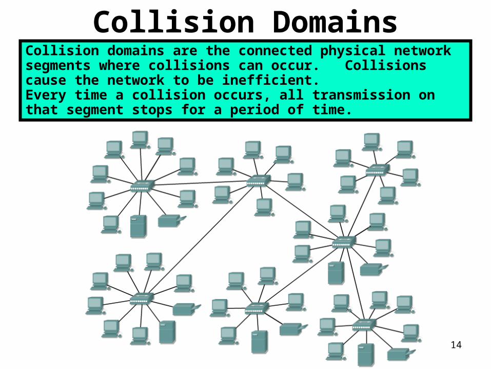
Collision DomainsCollision domains are the connected physical network segments where collisions can occur. Collisions cause the network to be inefficient. Every time a collision occurs, all transmission on that segment stops for a period of time.

15
Collision Domain Segmentation

16
The 5-4-3-2-1 RuleThe 5-4-3-2-1 rule requires that the following guidelines should not be exceeded:
Five segments of network media
Four repeaters or hubs
Three host segments of the network
Two link sections (no hosts)
One large collision domain
The 5-4-3-2-1 rule also provides guidelines to keep round-trip delay time in a shared network within acceptable limits.

17
Layer 2 BroadcastsTo communicate with all collision domains, protocols use broadcast and multicast frames at Layer 2 of the OSI model.
When a node needs to communicate with all hosts on the network, it sends a broadcast frame with a destination MAC address 0xFFFFFFFFFFFF.
This is an address to which the network interface card (NIC) of every host must respond.

18
Broadcast DomainsA broadcast domain is a grouping of collision domains that are connected by Layer 2 devices.
Breaking up a LAN into multiple collision domains increases the opportunity for each host in the network to gain access to the media. This effectively reduces the chance of collisions and increases available bandwidth for every host.
But broadcasts are forwarded by Layer 2 devices and if excessive, can reduce the efficiency of the entire LAN.
Broadcasts have to be controlled at Layer 3 with routers.

19
Data Flow Through a Network

20
What is a Segment?As with many terms and acronyms, segment has multiple meanings.
The dictionary definition of the term is as follows:
• A separate piece of something
• One of the parts into which an entity, or quantity is divided or marked
off as if by natural boundaries
In the context of data communication, the following definitions are used:
• Section of a network that is bounded by bridges, routers, or switches.
• In a LAN using a bus topology, a segment is a continuous electrical
circuit that is often connected to other such segments with repeaters.
• Term used in the TCP specification to describe a single transport layer unit of information – the Layer 4 Protocol Data Unit (PDU)

21