1 2 3 modeling the apparent and intrinsic viscoelastic re
TRANSCRIPT
1 2 3 4 5 6 7 8 9 10 11 12 13 14 15 16 17 18 19 20 21 22 23 24 25 26 27 28 29 30 31 32 33 34 35 36 37 38 39 40 41 42 43 44 45 46 47 48 49 50 51 52 53 54 55 56 57 58 59 60 61 62 63 64 65
* denotes corresponding author
Modeling the apparent and intrinsic viscoelastic relaxation of hydrating
cement paste
X. Lia, Z.C. Grasleya*, E.J. Garboczic, and J.W. Bullardb
aZachry Department of Civil Engineering, Texas A&M University
[email protected], [email protected]
bMaterials and Structural Systems Division, Engineering Laboratory, National Institute of Standards and
Technology, Gaithersburg, MD USA
[email protected], [email protected]
ABSTRACT
Finite element procedures combined with microstructure development modeling are
integrated to quantitatively predict the viscoelastic/viscoplastic relaxation of cement paste
due to intrinsic calcium silicate hydrate viscoelasticity and microstructure evolution
associated with the hydration process. The combined models are implemented in a
computational routine to predict time-dependent stress and strain fields in cement paste. The
model simulations suggest that inherent viscoelastic deformation caused by calcium silicate
hydrate is not necessarily the primary mechanism leading to the overall early-age
viscoelastic/viscoplastic behavior of cement paste. The effect of time-dependent dissolution
of cement grains occurring during the hydration process is substantial and should be
*Revised ManuscriptClick here to view linked References

1 2 3 4 5 6 7 8 9 10 11 12 13 14 15 16 17 18 19 20 21 22 23 24 25 26 27 28 29 30 31 32 33 34 35 36 37 38 39 40 41 42 43 44 45 46 47 48 49 50 51 52 53 54 55 56 57 58 59 60 61 62 63 64 65
considered as a significant mechanism for the apparent viscoelasticity/viscoplasticity of
cement paste.
Keywords: C-S-H [B]; Finite Element Analysis [C]; Microstructure [B]; Viscoelastic;
Dissolution; THAMES
1. Introduction
Previously, a model implementing the finite element method (FEM) was used to successfully
predict the elastic properties of cement paste based on the elastic properties of the
microscopic phases and their evolving spatial structure [1]. However, it is widely known that
cement paste exhibits viscoelastic/viscoplastic (VE/VP) effects in addition to the
instantaneous elastic effects; such time-dependent VE/VP effects have a significant impact on
the stress and strain fields in cementitious materials [2]. Theoretically predicting the VE/VP
relaxation moduli of cement paste is a difficult task. In addition to its complex, random,
composite matrix arrangement at the micrometer scale, the microstructure evolution of
cement paste during the hydration process is an additional important complexity, as its
response to load critically depends on loading histories relative to the time the new
components are formed.

1 2 3 4 5 6 7 8 9 10 11 12 13 14 15 16 17 18 19 20 21 22 23 24 25 26 27 28 29 30 31 32 33 34 35 36 37 38 39 40 41 42 43 44 45 46 47 48 49 50 51 52 53 54 55 56 57 58 59 60 61 62 63 64 65
The VE/VP behavior of cement paste has been traditionally attributed to the inherent VE/VP
behavior of the calcium silicate hydrate (C-S-H) phase [2], and based on this understanding,
many mechanisms towards C-S-H VE/VP behavior have been proposed, such as the seepage
theory [3, 4] and the viscous shear theory [3, 5]. Besides inherent C-S-H VE/VP effects,
researchers have also suggested other mechanisms leading to time-dependent deformation of
cement paste, including poromechanical effects (see, e.g., [6-11]) and dissolution of load
bearing phases [12, 13]. Poromechanical effects manifest as a time-dependent transfer of
stress from the pore fluid phase to the solid skeleton inside saturated cementitious materials,
which leads to an effective relaxation of the moduli [14, 15]. Similarly, an effective
relaxation of the moduli, shown in preliminary results of the model described in this present
paper, may also occur due to the redistribution of stress generated by the dissolution of load
bearing solid phases [16]. Since the effect of poromechanics is apparently only substantial
when the material is fully saturated, in this paper, the main VE/VP mechanisms considered
are the intrinsic VE/VP behavior of C-S-H and the time-dependent dissolution of cement
grains. While it is well known that drying of cementitious materials while under load
enhances deformation (i.e., the so-called “drying creep” or “Pickett effect”), the consideration
of drying is outside the scope of the present paper and thus will not be addressed.
The objective of this research is to develop a model using computational methods to predict
the evolution of VE/VP properties of hydrating cement paste based on the aforementioned
mechanisms. By carrying out virtual experiments using the model, the contribution of each
mechanism towards the overall VE/VP behavior of cementitious materials can be evaluated.
1 2 3 4 5 6 7 8 9 10 11 12 13 14 15 16 17 18 19 20 21 22 23 24 25 26 27 28 29 30 31 32 33 34 35 36 37 38 39 40 41 42 43 44 45 46 47 48 49 50 51 52 53 54 55 56 57 58 59 60 61 62 63 64 65
2. Methodology and Model Validation
2.1. Microstructure Modeling
The previously referenced prediction of cement paste elastic moduli involved utilizing the
microstructure model CEMHYD3D (CEMent HYDration in 3D) [17], which generated
lattice-based 3D digital microstructure images of specific cement pastes at specific degrees of
hydration. Each voxel in the 3D microstructure was treated as an eight-node tri-linear cubic
element in a finite element solver at the micrometer scale. By assigning individual phase
elastic moduli to each voxel (depending on which individual phase occupied each voxel) and
applying periodic displacement boundary conditions, the finite element program predicted the
full 3D stress and strain fields [1, 18, 19]. These fields were spatially averaged over the
microstructure to determine the composite elastic moduli at a given degree of hydration and
then compared to experiments where both elastic moduli and degree of hydration were
measured [20].
In the computational approach undertaken in this research, a next-generation hydration model
called THAMES (Thermodynamic Hydration And Microstructure Evolution) [21, 22] was
utilized to simulate the microstructure evolution during the hydration process at the
micrometer level. THAMES is capable of producing 3D snapshots of hydrating cement paste
microstructure at different ages based in part on thermodynamic equilibrium calculations and
phenomenological dissolution kinetics [21]. The input provided to THAMES was the phase
makeup (mass fractions of constituents) of the cement considered at the particle level, the
particle size distribution of the cement, and the water to cement ratio (w/c). THAMES
randomly placed the digital cement grains within a specified domain, and the grains began to
dissolve at the surface according to phenomenological dissolution kinetics functions. At each

1 2 3 4 5 6 7 8 9 10 11 12 13 14 15 16 17 18 19 20 21 22 23 24 25 26 27 28 29 30 31 32 33 34 35 36 37 38 39 40 41 42 43 44 45 46 47 48 49 50 51 52 53 54 55 56 57 58 59 60 61 62 63 64 65
time step, the pore fluid speciation from the previous time step was combined with the
change in speciation induced from dissolution since the previous step. Based on the new
speciation at the present time step, the thermodynamic engine GEMS (Gibbs Energy
Minimization) [23, 24] was utilized to find the equilibrium solution speciation and the mass
of each solid constituent in equilibrium with the solution. It was assumed that near-
equilibrium conditions were present between the hydration products and pore solution, which
is a reasonable approximation after about 12-24 hrs of hydration for typical portland cement
pastes. The new hydration products formed at a particular time step were spatially located
based on local geometric information regarding interfaces. This information included
restrictions on where a particular constituent can grow and empirical information regarding
the growth habit of the constituent (i.e. random, acicular, isotropic). The output from
THAMES at each time step is a representative microstructure of constituents, in which each
cubic voxel consists of a single phase.
2.2. Finite Element Method
Finite element procedures were rewritten in C++, based on the existing Fortran codes [18, 19],
to match THAMES, since it is also written in C++. The finite element codes were combined
with the THAMES microstructure model to develop an elastic moduli prediction model as
well as a VE/VP relaxation moduli prediction model. In each case, the THAMES
microstructure was meshed using a spatially aligned numerical discretization [25] such that
each voxel (consisting of a unique phase) became an eight node tri-linear cubic finite element.
In the elastic properties prediction model, each voxel was assigned isotropic elastic moduli.
For anisotropic crystalline phases, the effective average isotropic moduli were calculated as
the arithmetic average of the Voigt and Reuss polycrystalline bounds [26]. This procedure
1 2 3 4 5 6 7 8 9 10 11 12 13 14 15 16 17 18 19 20 21 22 23 24 25 26 27 28 29 30 31 32 33 34 35 36 37 38 39 40 41 42 43 44 45 46 47 48 49 50 51 52 53 54 55 56 57 58 59 60 61 62 63 64 65
was deemed an accurate approximation owing to the probable random orientation of these
phases within a given microstructure. The microstructure was subjected to strain-controlled
periodic displacement boundary conditions and the total mechanical energy stored inside the
whole microstructure was minimized to solve the boundary value problem [1, 19]. The
composite elastic moduli were calculated by solving the elastic equations on a regular finite
element mesh [20], based on the volume averaged stress of the composite under the specific
boundary condition. A similar approach has yielded elastic moduli that agree well with the
experimental results obtained from general porous materials and also cement paste specimens
fabricated using the same cement and w/c considered in the simulations [1, 27].
To predict the time-dependent VE/VP behavior of cement paste, the elastic microstructure
model was discretized in time to account for the time and (stress or strain) history dependent
mechanical properties. At each time step in the finite element calculations, the microstructure
model THAMES provided a snapshot of the 3D time-evolving microstructure, and similarly
to the elastic moduli prediction model, the VE/VP finite element model solved the strain-
controlled viscoelastic problem by minimizing the total energy stored in the microstructure at
each time step.1 The virtual work principle was used with the viscoelastic model to calculate
the mechanical energy of the viscoelastic phases inside the microstructure [28, 29].
In the domain Ω of the problem, the virtual work expression for stored mechanical energy is
derived under a virtual stress boundary condition induced by the traction condition
1 This solution procedure for the VE/VP material problem disregards any linear momentum in the body asso-ciated with its motion. This approach generates negligible error since the velocity of the time-dependent defor-mation is extremely slow under the boundary conditions considered.

1 2 3 4 5 6 7 8 9 10 11 12 13 14 15 16 17 18 19 20 21 22 23 24 25 26 27 28 29 30 31 32 33 34 35 36 37 38 39 40 41 42 43 44 45 46 47 48 49 50 51 52 53 54 55 56 57 58 59 60 61 62 63 64 65
i ji jt nσ= (1)
for all points lying on a part of the boundary denoted as 2S , where ijσ are components of the
Cauchy stress tensor and jn are components of the unit normal vector [30, 31]. A variational
form of virtual work for infinitesimal deformations is
2
..0ii i i i ij ij
Siu b d u d u u d dtδ δ δ ρ δε σ
Ω Ω Ω
Ω + Ω− Ω− Ω =∫ ∫ ∫ ∫ , (2)
where ρ is mass density, ib are body force components, iu are displacement components,
ijε are infinitesimal strain components, δ denotes an infinitesimal variation, and the
overhead dots denote partial differentiation with respect to time [29]. Under a quasi-static
state with a negligible inertia, the terms containing velocity components in eq. (2) can be
eliminated and the instantaneous stored energy in viscoelastic phases can be approximated as
12 ij ijkl kl i iC d u b dψ ε ε
Ω Ω
= Ω + Ω∫ ∫ , (3)
where ψ is the energy stored in viscoelastic phases and ijklC are components of
instantaneous elastic moduli. Through minimizing the total mechanical energy stored in the
microstructures, stress and strain fields of these microstructures at each time step can be
predicted through FEM. While cementitious materials are rarely subjected to large
deformation gradients on the macroscopic length scale – owing to their quasi-brittle nature –
it is possible that locally large deformation gradients might still occur in the microstructure.
While infinitesimal strains are considered in the analysis discussed herein, further study is
needed to determine the likelihood of finite strains in the microstructure.

1 2 3 4 5 6 7 8 9 10 11 12 13 14 15 16 17 18 19 20 21 22 23 24 25 26 27 28 29 30 31 32 33 34 35 36 37 38 39 40 41 42 43 44 45 46 47 48 49 50 51 52 53 54 55 56 57 58 59 60 61 62 63 64 65
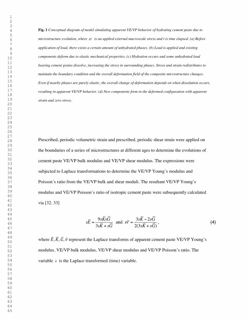
Fig. 1 Conceptual diagram of model simulating apparent VE/VP behavior of hydrating cement paste due to
microstructure evolution, where σ is an applied external macroscale stress and t is time elapsed. (a) Before
application of load, there exists a certain amount of unhydrated phases. (b) Load is applied and existing
components deform due to elastic mechanical properties. (c) Hydration occurs and some unhydrated load
bearing cement grains dissolve, increasing the stress in surrounding phases. Stress and strain redistributes to
maintain the boundary condition and the overall deformation field of the composite microstructure changes.
Even if nearby phases are purely elastic, the overall change of deformation depends on when dissolution occurs,
resulting in apparent VE/VP behavior. (d) New components form in the deformed configuration with apparent
strain and zero stress.
Prescribed, periodic volumetric strain and prescribed, periodic shear strain were applied on
the boundaries of a series of microstructures at different ages to determine the evolutions of
cement paste VE/VP bulk modulus and VE/VP shear modulus. The expressions were
subjected to Laplace transformations to determine the VE/VP Young’s modulus and
Poisson’s ratio from the VE/VP bulk and shear moduli. The resultant VE/VP Young’s
modulus and VE/VP Poisson’s ratio of isotropic cement paste were subsequently calculated
via [32, 33]
9 3 2 and 3 2(3 )
sKsG sK sGsE ssK sG sK sG
ν−
= =+ +
, (4)
where !", $%, &, ( represent the Laplace transforms of apparent cement paste VE/VP Young’s
modulus, VE/VP bulk modulus, VE/VP shear modulus and VE/VP Poisson’s ratio. The
variable s is the Laplace transformed (time) variable.

1 2 3 4 5 6 7 8 9 10 11 12 13 14 15 16 17 18 19 20 21 22 23 24 25 26 27 28 29 30 31 32 33 34 35 36 37 38 39 40 41 42 43 44 45 46 47 48 49 50 51 52 53 54 55 56 57 58 59 60 61 62 63 64 65
A major challenge in predicting the VE/VP behavior of cement paste is that microstructure
evolution associated with hydration (i.e., dissolution of cement phases and precipitation of
hydrates) occurs over the same time scale as VE/VP relaxation. This change of internal
structure leads to stress and strain redistribution inside the whole composite. A key
assumption in the model discussed herein is that when there is phase change in one voxel
between two successive time steps (e.g. from C3S to C-S-H), stress carried by the original
phase would be redistributed to surrounding phases upon dissolution (thus increasing the
stress carried by these phases), resulting in an apparent VE/VP deformation. This assumption
implies that stress redistribution takes place much faster than chemical phase changes.
Meanwhile, the newly formed phases must form in a stress-free state that conforms to the
preexisting deformed configuration, and no historical responses in this voxel before
formation occurs should be included in the finite element calculation. As a result, apparent
strain2 (i.e., strain that exists independent of the state of stress) is produced inside the
microstructure and information regarding apparent strain must be stored in the finite element
formulation for calculation purposes. Fig. 1 elaborates conceptually the redistribution of
stress and strain of an evolving microstructure under a general stress-controlled boundary
condition, which yields an apparent VE/VP response. The same apparent VE/VP response
appears under a strain-controlled period boundary condition, which is applied in the model.
The term “apparent VE/VP” moduli is reserved for modeling the constitutive behavior at the
macroscale induced by smaller length scale mechanisms that are not due to inherent VE
behavior of phases within the material.
2 Apparent strain is defined here, from a continuum mechanics perspective, as strain that exists independent of the state of stress. Unlike free strains (e.g., strain induced by changes in temperature or moisture state of the material), the apparent strain here does not involve a change in the atomic or molecular spacing from the refer-ence configuration. However, from a book-keeping perspective, apparent strain is treated in the same fashion as free strains.

1 2 3 4 5 6 7 8 9 10 11 12 13 14 15 16 17 18 19 20 21 22 23 24 25 26 27 28 29 30 31 32 33 34 35 36 37 38 39 40 41 42 43 44 45 46 47 48 49 50 51 52 53 54 55 56 57 58 59 60 61 62 63 64 65
To illustrate the process of the VE/VP model more specifically, Fig. 2 shows the simplified
flow chart for the computational scheme. At the first time step in the model, a strain-
controlled periodic boundary condition is applied on the microstructure of a particular age,
and the finite element calculation is carried out based on historical responses of each voxel
and the loading histories. For each voxel, the linearly viscoelastic constitutive relationship
may be expressed as [34]
( ) ( ) ( ) ( ) ( )0 0
t t
ij kl ijkl ijkl klt t s C s ds C t s s dsσ ε ε= − = −∫ ∫ɺ ɺ , (5)
where ( ) ijklC t are the components of the viscoelastic relaxation moduli tensor at time t. With
the involvement of discretized time steps in the finite element calculation, eq. (5) may be
approximated as
( ) ( ) ( ) ( ) ( ) ( )1
0 10
[ ]k n
ij n kl n ijkl kl k ijkl n k ijkl n kk
t t C t t C t t C t tσ ε ε= −
+=
= + − − −∑ , (6)
where 0t denotes the initial time when the periodic boundary condition is applied and it is
the time at ith time step. For those phases considered to be purely conservative (phases with
only elastic properties), the summation in eq. (6) becomes zero. With the calculated stress
and strain histories in each voxel, the total energy stored in the whole microstructure is
calculated and minimized at each time step to determine the resultant stress and strain fields
inside the microstructure, which are then spatially averaged to calculate the VE/VP moduli at
the macroscopic scale.

1 2 3 4 5 6 7 8 9 10 11 12 13 14 15 16 17 18 19 20 21 22 23 24 25 26 27 28 29 30 31 32 33 34 35 36 37 38 39 40 41 42 43 44 45 46 47 48 49 50 51 52 53 54 55 56 57 58 59 60 61 62 63 64 65
At each subsequent time step, the new microstructure for the age corresponding to that time
step is input into the model and comparison between the previous microstructure and the
current microstructure is carried out on every voxel to check for phase change. Voxels with
phase change are recorded and the previous mechanical responses of such voxels are
disregarded in future calculations. Furthermore, any stresses within the dissolved phase are
redistributed to the surrounding voxels. The VE moduli of phase-changed voxels are relaxed
according to the loading histories subsequent to the time they are formed during all the
following time steps. That is, if one voxel experiences phase change at the i th time step
( 0t t= ), in all subsequent time steps the moduli of this specified voxel are no longer based on
the mechanical properties of the previous phase, but on the current changed phase. If the
voxel is switched to an elastic phase, the moduli of this voxel are kept constant in all the
following time steps with the current phase elastic moduli; if the voxel is switched to a VE
phase (such as C-S-H), the moduli of this voxel would be assigned a VE moduli with the
relaxation starting at time 0t t= , the time at which phase change occurs, for all the following
time steps. Calculations are carried out based on the renewed response histories and moduli.
The second step in the routine is repeated until all time steps are complete.
Fig. 2 Simplified flow chart for the computational finite element procedure predicting the apparent VE/VP
behavior of cement paste.
The computational scheme and associated material model allows investigation of relaxation
caused by both intrinsic C-S-H viscoelasticity and microstructure evolution concurrently. It

1 2 3 4 5 6 7 8 9 10 11 12 13 14 15 16 17 18 19 20 21 22 23 24 25 26 27 28 29 30 31 32 33 34 35 36 37 38 39 40 41 42 43 44 45 46 47 48 49 50 51 52 53 54 55 56 57 58 59 60 61 62 63 64 65
also can separately model the VE/VP relaxation of cement paste due strictly to intrinsic C-S-
H relaxation or the apparent VE/VP relaxation of cement paste due strictly to dissolution of
certain phases. One can evaluate the contribution of intrinsic relaxation to the overall VE/VP
behavior by defining a unique VE or VP constitutive property for any given phase while
utilizing unchanging microstructure for all time steps or one can strictly examine the effect of
microstructure evolution by utilizing time-evolving microstructures of composites with
purely elastic phases. This separation allows us to judge the relative magnitude of these two
sources of VE/VP behavior, as compared to experiment, which always mixes the two sources.
2.3. Model Validation
The advantage of the newly generated model and finite element implementation is that it is
able to simulate apparent VE/VP effects that occur due to microstructure evolution while
simultaneously considering intrinsic VE/VP properties associated with phases that exhibit
VE/VP behavior. As far as the authors are aware, there are no commercially available FEM
software packages capable of validating this novel aspect of the new software. However, a
simple simulation was performed to evaluate the physical rationality of the computed results.
The simulation considered a THAMES generated microstructure for a 0.40 w/c cement paste
(simulated under an isothermal condition of 25° C) that utilized chemical and physical data
for a certain well-characterized portland cement. Microstructure snapshots were taken over
the course of several days of age. Each phase in the microstructure was assigned elastic
properties taken from [1], except C-S-H was assigned a VE Young’s modulus prescribed as
( )( ) 11.2 11.2exp 0.2 GPaE t t= + − , which allows 50% of the instantaneous elastic Young’s
modulus to be relaxed as t→∞. The Poisson’s ratio of the C-S-H was prescribed to be time-
independent as 0.25ν = . As shown in Fig. 3(a), during the first 13 days, a constant periodic

1 2 3 4 5 6 7 8 9 10 11 12 13 14 15 16 17 18 19 20 21 22 23 24 25 26 27 28 29 30 31 32 33 34 35 36 37 38 39 40 41 42 43 44 45 46 47 48 49 50 51 52 53 54 55 56 57 58 59 60 61 62 63 64 65
bulk strain ( 11 22 33= =ε ε ε ) of 0.01 was applied to the composite material, and this applied
strain was suddenly removed at the 13th day, forcing the material to return back to its original
geometry of zero bulk strain.
Fig. 3 Virtual experiment of 0.40 w/c cement paste with an evolving microstructure under a virtual strain
controlled boundary condition. (a) Virtual applied bulk strain history with a sudden removal at 13th day. (b)
Mechanical response (apparent volumetric stress) of viscoelastic composite material under boundary history (a).
The VE Young’s modulus of C-S-H was assumed to be ( ) 11.2 11.2 exp( 0.2 )E t t GPa= + − , where t is in days and
the Poisson’s ratio of C-S-H was assumed to be a constant value of 0.25. The elastic properties of all other
phases were taken from [1]. As illustrated by diagrams using simplified parallel phase geometry, the sudden
drop of the apparent volumetric stress into a negative magnitude was associated with the tensile pressure
required to force those phases formed after the initial application of bulk strain back to a zero strain condition.
Fig. 3(b) shows the apparent macroscopic volumetric stress (the average value of 11σ , 22σ
and 33σ ) of the composite predicted by the finite element model. During the first 13 d, the
composite showed smooth relaxation under constant controlled strain due to the two stress-
relaxation mechanisms (i.e., phase dissolution of cement grains and intrinsic VE properties of
the C-S-H), and at the 13th day, with the sudden removal of the periodic bulk strain, the
volumetric stress of the material also exhibited a sudden drop. However, instead of returning
back to zero as the external controlled strain did, the volumetric stress assumed a negative
value. The existence of the residual stress within the composite is not unexpected. As
illustrated conceptually by the diagrams in Fig. 3(b), when a controlled strain is applied, the

1 2 3 4 5 6 7 8 9 10 11 12 13 14 15 16 17 18 19 20 21 22 23 24 25 26 27 28 29 30 31 32 33 34 35 36 37 38 39 40 41 42 43 44 45 46 47 48 49 50 51 52 53 54 55 56 57 58 59 60 61 62 63 64 65
existing phases deform under the external boundary condition. During the hydration process,
some phases inside the composite material dissolve and form new phases in the deformed
configuration in a stress-free state. When the bulk strain of the microstructure was suddenly
forced back to zero in the simulation, opposing stresses were necessarily generated within the
latter-formed phases, leading to a negative volumetric stress. A very simple model, a spring
of length L, serves to further illustrate this point. Suppose the spring is extended in tension by
an amount x and held there. Another spring is added in parallel, of unextended length L/ = L
+ x. This second spring is longer, but carries no force. When the first spring is released, it will
not relax all the way back to zero extension but will retain some amount of tension since the
second spring will be simultaneously pulled into compression.
2.4. Virtual Experiments
To further exploit the utility of the newly generated model, a sequence of virtual experiments
were performed to probe the contribution of each VE/VP mechanism (intrinsic C-S-H
viscoelasticity or microstructure evolution) to overall early-age VE/VP behavior of cement
paste. By applying purely controlled periodic volumetric strain and purely controlled periodic
shear strain on the boundary of a series of microstructures with 3100 voxels (with the
dimension of each voxel as 1 µm3) at different ages, the evolution of apparent cement paste
VE/VP bulk modulus and VE/VP shear modulus were simulated by the model. The apparent
VE/VP Young’s modulus and the apparent VE/VP Poisson’s ratio were then calculated using
eq. (4). All microstructures utilized in the virtual experiments were generated by THAMES
on simulated sealed cement pastes of CCRL Proficiency Sample Cement 168, simulated
under an isothermal, sealed condition of 25 ) (298 K) [35], and the mechanical elastic
moduli of each individual phase (e.g. C3S, C-S-H) were taken from previous studies

1 2 3 4 5 6 7 8 9 10 11 12 13 14 15 16 17 18 19 20 21 22 23 24 25 26 27 28 29 30 31 32 33 34 35 36 37 38 39 40 41 42 43 44 45 46 47 48 49 50 51 52 53 54 55 56 57 58 59 60 61 62 63 64 65
elaborated in [1]. The cement composite microstructures considered different values of w/c
varying from 0.35 to 0.50, and ages from 1 d to 56 d.
3. Results and Discussion
3.1. Viscoelasticity/Viscoplasticity due to Microstructure Evolution
To evaluate the apparent VE/VP behavior occurring strictly due to microstructure evolution,
microstructures of cement composites with pure elastic phases (no inherent viscoelasticity) at
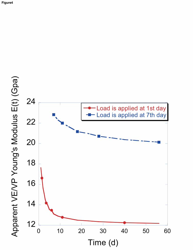
different ages (from 1 d to 56 d) were first considered. Fig. 4 shows the predicted apparent
VE/VP Young’s modulus of 0.40 w/c cement paste under constant periodic strain boundary
condition applied at different ages of 1 d and 7 d. The relaxation shown in Fig. 4 was due
entirely to the time-dependent dissolution of cement grains. From the predicted results, one
can see that the apparent VE/VP behavior caused by dissolution of cement grains is
substantial. Thus, microstructure evolution associated with the hydration process should be
included as a significant mechanism in cement paste VE/VP behavior. Additionally, as the
rate of relaxation of cement paste slows as cement paste ages (because of the decreasing
hydration rate with age), the well-known aging effect of cement paste VE/VP behavior is
demonstrated by the hydration-related dissolution mechanism. Time-dependent, stress-
induced dissolution of hydrates in cementitious materials might also induce apparent
viscoelastic effects, but at this time it is unclear how cement composites dissolve under
various external stress conditions, and thus stress-induced dissolution is not considered in this
paper.

1 2 3 4 5 6 7 8 9 10 11 12 13 14 15 16 17 18 19 20 21 22 23 24 25 26 27 28 29 30 31 32 33 34 35 36 37 38 39 40 41 42 43 44 45 46 47 48 49 50 51 52 53 54 55 56 57 58 59 60 61 62 63 64 65
Fig. 4 Apparent VE/VP Young’s modulus of 0.40 w/c cement paste when loaded at different ages (1 d and 7 d).
In this graph, apparent VE/VP behavior was considered to occur strictly due to dissolution of load bearing
cement grains. The dissolution of load bearing cement grains resulted in significant apparent VE/VP behavior
for the macroscopic cement pastes, and was able to account for the well-known aging effect of VE/VP behavior
of cement paste.
3.2 Intrinsic C-S-H Viscoelasticity
To further investigate the mechanisms of cement paste VE/VP behavior, a simulation was
carried out to compare the effect of intrinsic C-S-H viscoelasticity relative to dissolution
effects on the overall VE/VP behavior of cement paste.
Intrinsic viscoelasticity of C-S-H has been historically regarded as the primary mechanism
leading to cement paste VE/VP behavior. However, recent experimental results suggest that
C-S-H may not exhibit as much creep and relaxation as previously thought [36]. A clear
demonstration is required to show the contribution of C-S-H intrinsic viscoelasticity towards
overall cement paste VE/VP properties. Thus, a simulation was performed where dissolution
effects were ignored and periodic boundary conditions were applied onto non-aging
microstructures; that is, the microstructures did not evolve with time during the simulation
and the simulated cement paste relaxation was due entirely to inherent C-S-H viscoelasticity.
Since, due to experimental challenges, there are no sufficient data currently available for
modeling creep or relaxation of the C-S-H phase over several days, for simulation purposes,
the viscoelastic Young’s modulus of C-S-H was assumed to be
( ) 11.2 11.2 exp( 0.2 )E t t GPa= + − , where t is in unit of days and the Poisson’s ratio of C-S-H
was set to be a time-independent constant value of 0.2. All other phases in the microstructure
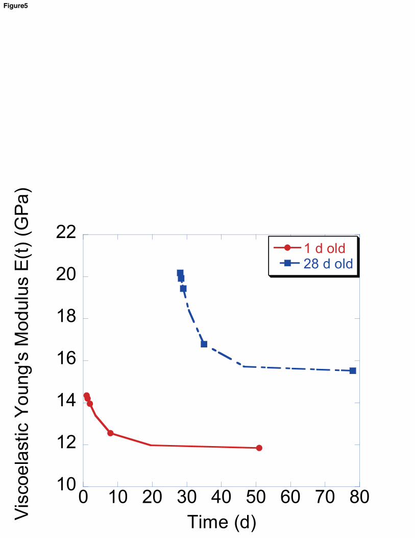
were assigned to be elastic with properties taken from [1]. Fig. 5 shows the apparent VE
1 2 3 4 5 6 7 8 9 10 11 12 13 14 15 16 17 18 19 20 21 22 23 24 25 26 27 28 29 30 31 32 33 34 35 36 37 38 39 40 41 42 43 44 45 46 47 48 49 50 51 52 53 54 55 56 57 58 59 60 61 62 63 64 65
Young’s modulus associated with the response of 0.45 w/c paste, where the relaxation was
due strictly to the intrinsic viscoelastic relaxation of C-S-H.
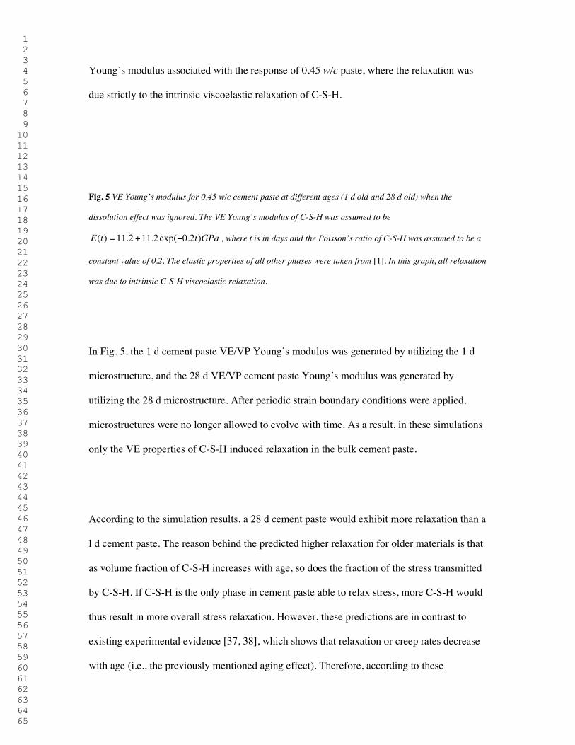
Fig. 5 VE Young’s modulus for 0.45 w/c cement paste at different ages (1 d old and 28 d old) when the
dissolution effect was ignored. The VE Young’s modulus of C-S-H was assumed to be
( ) 11.2 11.2 exp( 0.2 )E t t GPa= + − , where t is in days and the Poisson’s ratio of C-S-H was assumed to be a
constant value of 0.2. The elastic properties of all other phases were taken from [1]. In this graph, all relaxation
was due to intrinsic C-S-H viscoelastic relaxation.
In Fig. 5, the 1 d cement paste VE/VP Young’s modulus was generated by utilizing the 1 d
microstructure, and the 28 d VE/VP cement paste Young’s modulus was generated by
utilizing the 28 d microstructure. After periodic strain boundary conditions were applied,
microstructures were no longer allowed to evolve with time. As a result, in these simulations
only the VE properties of C-S-H induced relaxation in the bulk cement paste.
According to the simulation results, a 28 d cement paste would exhibit more relaxation than a
l d cement paste. The reason behind the predicted higher relaxation for older materials is that
as volume fraction of C-S-H increases with age, so does the fraction of the stress transmitted
by C-S-H. If C-S-H is the only phase in cement paste able to relax stress, more C-S-H would
thus result in more overall stress relaxation. However, these predictions are in contrast to
existing experimental evidence [37, 38], which shows that relaxation or creep rates decrease
with age (i.e., the previously mentioned aging effect). Therefore, according to these

1 2 3 4 5 6 7 8 9 10 11 12 13 14 15 16 17 18 19 20 21 22 23 24 25 26 27 28 29 30 31 32 33 34 35 36 37 38 39 40 41 42 43 44 45 46 47 48 49 50 51 52 53 54 55 56 57 58 59 60 61 62 63 64 65
simulations, C-S-H relaxation cannot be the primary mechanism of early-age cement paste
VE/VP behavior unless the VE properties of the C-S-H itself dramatically change with age. If
C-S-H phases experience significant aging, the functions for C-S-H VE moduli must vary
relative to the age when specific particles of C-S-H are formed. This effect was not present in
the current model.
3.3. Predicted Effects of Different w/c
To investigate the influence of different values of w/c on the apparent VE/VP Young’s
modulus at different loading ages, microstructures of cement paste with purely elastic phases
(with elastic properties taken from [1]) and w/c from 0.35 to 0.50 were utilized. In this set of
simulations, the VE/VP relaxation of cement paste occurred strictly due to dissolution of load
bearing cement grains. Fig. 6 shows the predicted results of apparent VE/VP Young’s
modulus for different values of w/c as well as the normalized apparent VE/VP Young’s
modulus, which are normalized by the instantaneous elastic Young’s modulus at loading ages
of 1 d and 7 d. As shown in Fig. 6(a) and Fig. 6(b), older cement pastes establish lower
relaxation rates for all different w/c considered because of the decreasing hydration rate (and
thus dissolution rate) with age, which is consistent with the discussion in previous sections
and experimental results. According to Fig. 6(c) and Fig. 6(d), at an early age of 1 d, the
normalized results clearly show that lower w/c results in a greater percent relaxation than
higher w/c. This simulation result agrees with experimental data from Vichit-Vadakan and
Scherer [37], which shows that lower w/c cement pastes experience larger relaxation than
higher w/c pastes at early ages. According to the model discussed here, this experimentally
observed ranking may occur because dissolution of load bearing cement grains is the
dominant factor affecting the relaxation rate at early ages due to the high rate of hydration.

1 2 3 4 5 6 7 8 9 10 11 12 13 14 15 16 17 18 19 20 21 22 23 24 25 26 27 28 29 30 31 32 33 34 35 36 37 38 39 40 41 42 43 44 45 46 47 48 49 50 51 52 53 54 55 56 57 58 59 60 61 62 63 64 65
As low w/c generates higher hydration rate at early age, a larger relaxation rate with low w/c
paste is observed. At later loading ages, on the other hand, higher w/c results in larger
relaxation [2]. This larger relaxation for higher w/c at later ages is likely due in part to the
lower fraction of solid phases in high w/c cement pastes, which results in a smaller volume of
available stress transferring phases. That is, when load bearing cement grains within a high
w/c paste dissolve during a single time step, there would be a lower volume of previously
formed solid phases (because of the high w/c) sharing the redistributed stress, leading to a
higher relaxation rate.
Fig. 6 Apparent viscoelastic Young’ modulus for different w/c at loading age of (a) 1 d and (b) 7 d and
normalized apparent VE/VP relaxation at loading age of (c) 1 d and (d) 7 d, where apparent VE/VP Young’s
modulus E(t) was normalized by instantaneous elastic Young’s modulus. VE/VP behavior was considered to
occur strictly due to microstructure evolution.
3.4 Evolution of Stresses
Besides the prediction of the effect of age and w/c on the apparent VE/VP properties of
cement paste, predictions of the evolution of stresses (volumetric stress and deviatoric stress)
carried by different phases (hydrated phases and unhydrated phases) inside cement paste
composites also become achievable through the computational scheme.

1 2 3 4 5 6 7 8 9 10 11 12 13 14 15 16 17 18 19 20 21 22 23 24 25 26 27 28 29 30 31 32 33 34 35 36 37 38 39 40 41 42 43 44 45 46 47 48 49 50 51 52 53 54 55 56 57 58 59 60 61 62 63 64 65
Volumetric stress is the stress tending to change the volume of the body, with magnitude
given by
11 22 33 1
3 3Ip σ σ σ+ +
= = , (7)
where p is the volumetric stress, iI are the three invariants of the stress tensor and
11 22 33, ,σ σ σ are normal stresses.
Deviatoric stress is the stress tending to distort the stressed body. Components of the stress
deviator tensor are given by
11 12 13 11 12 13
21 22 23 21 22 23
31 32 33 31 32 33
[ ]ij
s s s ps s s s p
s s s p
σ − σ σ = = σ σ − σ σ σ σ −
, (8)
where ijs is deviatoric stress, and ijσ are the components of the overall stress tensor. A scalar
measure of deviatoric stress magnitude is
21 2
1 12 3ij jis s s I I= = − , (9)
where s is the scalar deviatoric stress and i, j = 1, 2, or 3.
Since both volumetric stress and deviatoric stress are closely related to the three invariants of
the stress tensor, their evolution with time can be representative of the corresponding
evolutions of the general stress distribution inside the microstructure. Fig. 7 shows the
predicted evolution of p and s carried by hydrated phases and unhydrated phases at
different ages. In this figure, p for each phase is normalized by total volumetric stress

1 2 3 4 5 6 7 8 9 10 11 12 13 14 15 16 17 18 19 20 21 22 23 24 25 26 27 28 29 30 31 32 33 34 35 36 37 38 39 40 41 42 43 44 45 46 47 48 49 50 51 52 53 54 55 56 57 58 59 60 61 62 63 64 65
carried by the whole microstructure and s for each phase is normalized by total deviatoric
stress carried by the whole microstructure. The normalization is expressed according to
/ ( )( )
( )hydrated unhydrated
N
tt
tσ
σσ =
< >∑ (10)
where ( )Ntσ is either normalized volumetric or deviatoric stress at time t,
/ ( )hydrated unhydrated tσ∑ is the summed volumetric or deviatoric stress over hydrated or
unhydrated voxels at time t, and ( )tσ< > is the integrated volumetric or deviatoric stress
over the whole volume of the microstructure at time t. Microstructures constructed
considering 0.40 w/c with pure elastic phases at different ages were utilized in the model, and
the elastic properties of all phases were taken from [1].
Fig. 7 Normalized volumetric stress and deviatoric stress carried by hydrated phases and unhydrated phases
inside cement paste microstructure under loading age of 1 d. The summed volumetric and deviatoric stresses
carried by hydrated phases and unhydrated phases at time t are normalized by total volumetric stress or total
deviatoric stress carried by the whole microstructure at time t, respectively.
As C-S-H creep and relaxation has historically been considered the dominant mechanism
leading to cement paste creep and relaxation, some constitutive models, such as the
solidification theory [39], have been developed based on this understanding. Although the
solidification theory appears to have been developed with a uniaxial stress state in mind [40],
under any specific boundary conditions, evolutions of volumetric stress and deviatoric stress
with time should all be capable of representing the general stress evolutions inside the
microstructure, as discussed in previous paragraphs of this section. Due to equilibrium

1 2 3 4 5 6 7 8 9 10 11 12 13 14 15 16 17 18 19 20 21 22 23 24 25 26 27 28 29 30 31 32 33 34 35 36 37 38 39 40 41 42 43 44 45 46 47 48 49 50 51 52 53 54 55 56 57 58 59 60 61 62 63 64 65
requirements, the normalized, spatially averaged stress carried by the solidified products
(equivalent to hydration products) in the solidification theory may be calculated through
( )( )( )
total ttt
σσ =
ν (11)
where ( )tν is the aging function describing the volume fraction of solidified phases, and
( )total tσ is the normalized total stress, either volumetric stress or deviatoric stress, predicted
by the present model. Note that the solidification theory does not allow for any stress being
carried by the unhydrated cement, even after the cement paste has set. From a simple
composite theory view, it is clear that if solid phases are connected to the main solid
backbone, they will carry load. Computations have shown that at lower values of w/c, the
effective elastic moduli are significantly affected by the unhydrated cement [1].
For comparison purposes, the curves of normalized stresses carried by solidified phases
calculated via the new model presented in this paper are obtained by summing all normalized
stresses carried by the phases that solidify after load is applied. The evolution of stresses
carried by the hydration products after the application of load (at age of 1 d) as predicted by
the solidification theory and the new model are shown together in Fig. 8. The predictions
considered a 0.40 w/c cement paste hydrating under isothermal conditions (25° C).
Fig. 8 Comparison between the new model developed herein and the solidification theory regarding normalized
(a) volumetric and (b) deviatoric stress carried by solidified phases (hydration products). The stresses are
normalized by instantaneous total stress carried by the microstructure.

1 2 3 4 5 6 7 8 9 10 11 12 13 14 15 16 17 18 19 20 21 22 23 24 25 26 27 28 29 30 31 32 33 34 35 36 37 38 39 40 41 42 43 44 45 46 47 48 49 50 51 52 53 54 55 56 57 58 59 60 61 62 63 64 65
The solidification theory predicts that the average stress carried by solidified or hydrated
phases decreases with time, which results from the presumption that only solidified phases
may transmit stress. The solidification theory implies that hydration products are non-aging
viscoelastic materials and aging arises in the bulk scale due to the increase in load bearing
materials as a result of solidification and deposition of hydration products. As hydration
progresses, each newly formed layer of the hydration products solidifies in a stress-free state
and these layers are only subject to loads after they form. As a result of the predicted decrease
in stress carried by solidified phases (including C-S-H) as hydration progresses, the
solidification theory can account for the early-age aging effect through reduced C-S-H creep
as stress in that phase decreases. However, according to the model developed herein and as
shown in Fig. 7, the total stress carried by solidified phases increases with age. This increase
occurs because the new model accounts for the fact that stress may be transmitted by both
hydrated and unhydrated phases (hydrostatic stresses may be transmitted by cement grains at
any age, while deviatoric stresses may only be transmitted once percolation of the solid
skeleton has occurred). Since unhydrated phases are allowed to carry stress, their dissolution
results in an increase in stress on hydration products. Thus, the solidification theory is only
able to capture early-age aging effects while considering C-S-H viscoelasticity as a primary
mechanism for early-age cement paste creep and relaxation because the ability of cement
grains to transmit stress is neglected.
4. Conclusions
A computational scheme that couples a microstructure evolution model and a time-stepping
finite element method capable of tracking phase formation is developed in this paper to
predict the apparent VE/VP properties of cement paste as a function of time-evolving

1 2 3 4 5 6 7 8 9 10 11 12 13 14 15 16 17 18 19 20 21 22 23 24 25 26 27 28 29 30 31 32 33 34 35 36 37 38 39 40 41 42 43 44 45 46 47 48 49 50 51 52 53 54 55 56 57 58 59 60 61 62 63 64 65
microstructures. From the model simulations, the apparent VE/VP behavior of hydrating
cement paste due to dissolution of cement grains is a significant factor in the overall early-age
creep and relaxation of the paste. The main reasons behind this are the stress transmission from
dissolved load bearing phases to surrounding hydrated phases or cement grains, and the
generation of apparent strain in the new components that form in deformed configurations
(i.e., the newly formed phases have a deformation gradient but no stress). Simulation results
also indicate that intrinsic C-S-H viscoelasticity is not likely the primary mechanism leading
to the early-age creep and relaxation behavior of cementitious materials; this is because
significant C-S-H relaxation results in simulated macroscopic behavior that is in conflict with
experimental evidence of early-age aging effects.
The comparison between the evolution of stresses within hydration products predicted by the
new computational scheme and that predicted by the solidification theory indicates that the
specific assumption made about the extent to which unhydrated phases can transmit stress is
key to interpreting VE/VP mechanisms of cement paste. If one stipulates that unhydrated
phases do not carry stress (as with the solidification theory), then increased formation of C-S-
H can lead to aging of VE/VP properties of cement paste (e.g., reductions in creep or
relaxation rates at later ages). However, as demonstrated by the new computational scheme
and model presented herein, if one presumes that unhydrated phases may transmit stress once
the solid phases form a percolated network, then their dissolution results in an increase in
stress on hydration products as hydration progresses. This increase in stress in the less stiff
hydration products results in a greater relaxation rate, counteracting any reduction in rate due
to the increased formation of C-S-H; thus, the formation of C-S-H does not act as a source of
aging of VE/VP properties of cement paste. Conversely, the slowing of the cement

1 2 3 4 5 6 7 8 9 10 11 12 13 14 15 16 17 18 19 20 21 22 23 24 25 26 27 28 29 30 31 32 33 34 35 36 37 38 39 40 41 42 43 44 45 46 47 48 49 50 51 52 53 54 55 56 57 58 59 60 61 62 63 64 65
dissolution process (associated with the hydration reaction) with time may lead to lower
creep and relaxation rates of cement paste at later ages, contributing strongly to the early age
aging of cement paste.
The model discussed in this paper is yet unable to fully explain certain observed VE/VP
behavior of cement paste, including overall observed magnitude and differences between
responses associated with tensile and compressive stresses. Thus, additional mechanisms
must be considered in addition to hydration induced cement grain dissolution.
Acknowledgments
This research was supported by the National Science Foundation CAREER Award Program
under grant numbers 0843979 and 1327314. Any opinions, findings, and conclusions or
recommendations expressed in this material are those of the author(s) and do not necessarily
reflect the views of the National Science Foundation.
References
[1] Haecker CJ, Garboczi EJ, Bullard JW, Bohn RB, Sun Z, Shah SP, et al. Modeling the
linear elastic properties of Portland cement paste. Cement and Concrete Research.
2005;35(10):1948-60.
[2] Mindess S, Young JF, Darwin D. Concrete. 2nd ed. Upper Saddle River, NJ: Prentice
Hall; 2002.
[3] Tamtsia BT, Beaudoin JJ. Basic creep of hardened cement paste A re-examination of the
role of water. Cement and Concrete Research. 2000;30(9):1465-75.

1 2 3 4 5 6 7 8 9 10 11 12 13 14 15 16 17 18 19 20 21 22 23 24 25 26 27 28 29 30 31 32 33 34 35 36 37 38 39 40 41 42 43 44 45 46 47 48 49 50 51 52 53 54 55 56 57 58 59 60 61 62 63 64 65
[4] Powers TC. Mechanisms of shrinkage and reversible creep of hardened portland cement
paste Proceedings of International Conference On the Structure of Concrete. London,
England: Cement and Concrete Association; 1968.
[5] Ruetz W. A hypothesis for the creep of hardened cement paste and the influence of
simultaneous shrinkage Proceedings of International Conference On the Structure of
Concrete. London, England: Cement and Concrete Association; 1968.
[6] Leung CK, Grasley ZC. Poromechanical damping of cementitious materials. Journal of
Materials in Civil Engineering. 2012;24(2):232-8.
[7] Grasley ZC, Leung CK. Desiccation shrinkage of cementitious materials as an aging,
poroviscoelastic response. Cement and Concrete Research. 2011;41(1):77-89.
[8] Grasley ZC, Scherer GW, Lange DA, Valenza JJ. Dynamic pressurization method for
measuring permeability and modulus: II. cementitious materials. Materials and Structures.
2007;40(7):711-21.
[9] Coussy O, Monteiro PJM. Poroelastic model for concrete exposed to freezing
temperatures. Cement and Concrete Research. 2008;38(1):40-8.
[10] Scherer GW. Characterization of saturated porous bodies. Materials and
Structures/Materiaux et Constructions. 2004;37(265):21-30.
[11] Ulm FJ, Constantinides G, Heukamp FH. Is concrete a poromechanics material? - A
multiscale investigation of poroelastic properties. Materials and Structures/Materiaux et
Constructions. 2004;37(265):43-58.
[12] Suter M, Benipal G. Constitutive model for aging thermoviscoelasticity of reacting
concrete I: theoretical formulation. Mechanics of Time-Dependent Materials.
2010;14(3):277-90.
[13] Jensen M, Hansen PF. Autogenous deformation and change of the relative humidity in
silica fume-modified cement paste. ACI Materials Jounal. 1996;93(6):539-43.

1 2 3 4 5 6 7 8 9 10 11 12 13 14 15 16 17 18 19 20 21 22 23 24 25 26 27 28 29 30 31 32 33 34 35 36 37 38 39 40 41 42 43 44 45 46 47 48 49 50 51 52 53 54 55 56 57 58 59 60 61 62 63 64 65
[14] Jones CA, Grasley ZC. Correlation of hollow and solid cylinder dynamic pressurization
tests for measuring permeability. Cement and Concrete Research. 2009;39(4):345-52.
[15] Grasley Z, Scherer G, Lange D, Valenza J. Dynamic pressurization method for
measuring permeability and modulus: II. cementitious materials. Materials and Structures.
2007;40(7):711-21.
[16] Grasley ZC, Jones CA, Li X, Garboczi EJ, Bullard JW. Elastic and viscoelastic
properties of calcium silicate hydrate. NICOM 4: 4th International Symposium on
Nanotechnology in Consturction2012.
[17] Bentz DP. Quantitative comparison of real and CEMHYD3D model microstructures
using correlation functions. Cement and Concrete Research. 2006;36(2):259-63.
[18] Garboczi EJ. Finite element and finite difference programs for computing the linear
electric and elastic properties of digital images of random materials. Building and Fire
Research Laboratory,National Institute of Standards and Technology; 1998.
[19] Bohn RB, Garboczi EJ. User manual for finite element and finite difference programs: A
parallel version of NISTIR-6269. Gaithersburg: U.S. Department of commerce, Technology
Administration, National Institute of Standards and Technology, Information Technology
Laboratory, Building and Fire Research Labortory; 2003.
[20] Garboczi EJ, Day AR. An algorithm for computing the effective linear elastic properties
of heterogeneous materials: Three-dimensional results for composites with equal phase
poisson ratios. Journal of the Mechanics and Physics of Solids. 1995;43(9):1349-62.
[21] Bullard JW, Lothenbach B, Stutzman PE, Snyder KA. Coupling thermodynamics and
digital image models to simulate hydration and microstructure development of portland
cement pastes. Journal of Materials Research. 2011;26(4):609-22.
[22] Lothenbach B, Winnefeld F. Thermodynamic modelling of the hydration of portland
cement. Cement and Concrete Research. 2006;36(2):209-26.

1 2 3 4 5 6 7 8 9 10 11 12 13 14 15 16 17 18 19 20 21 22 23 24 25 26 27 28 29 30 31 32 33 34 35 36 37 38 39 40 41 42 43 44 45 46 47 48 49 50 51 52 53 54 55 56 57 58 59 60 61 62 63 64 65
[23] Kulik DA. Gibbs energy minimization approach to modeling sorption equilibria at the
mineral-water interface: Thermodynamic relations for multi-site-surface complexation.
American Journal of Science. 2002;302(3):227-79.
[24] Kulik DA. Dual-thermodynamic estimation of stoichiometry and stability of solid
solution end members in aqueous–solid solution systems. Chemical Geology. 2006;225(3–
4):189-212.
[25] Zohdi TI. Homogenization Methods and Multiscale Modeling. Encyclopedia of
Computational Mechanics: John Wiley & Sons, Ltd; 2004.
[26] Watt JP, Peselnick L. Clarification of the HashinϋShtrikman bounds on the effective
elastic moduli of polycrystals with hexagonal, trigonal, and tetragonal symmetries. Journal of
Applied Physics. 1980;51(3):1525 - 31.
[27] Kamali S, Moranville M, Garboczi E, Prené S, Gérard B. Influence of hydrate
dissolution by water on the Young’s modulus of cement-based materials. In: de Borst MP-C,
van Mier, Balkema, editor. FRAMCOS-5. Vail, CO, USA April 11, 2004.
[28] Bower AF. Applied mechanics of solids. Brown University, Providence, Rhode Island,
USA CRC Press; 1 edition 2009.
[29] Zienkiewicz OC, Taylor RL. Finite element method (5th edition) Volume 2 - solid
mechanics: Butterworth-Heinemann 2000; 2000.
[30] Lubliner J. Plasticity theory (revised edition). University of California at Berkeley:
Pearson Education, Inc.; 2008.
[31] Fung Y, Tong P. Classical and computational solid mechanics. Volume 1 of Advanced
series in engineering science: World Scientific Publishing Company; 2001.
[32] Timnoshenko SP, Goodier JN. Theory of elasticity. New York,: McGraw-Hill; 1970.
[33] Landau LD, Lifshitz EM. Theory of elasticity. 3rd ed. Oxford: Pergamon; 1986.

1 2 3 4 5 6 7 8 9 10 11 12 13 14 15 16 17 18 19 20 21 22 23 24 25 26 27 28 29 30 31 32 33 34 35 36 37 38 39 40 41 42 43 44 45 46 47 48 49 50 51 52 53 54 55 56 57 58 59 60 61 62 63 64 65
[34] Wineman AS, Rajagopal KR. Mechanical response of polymers: An introduction.
Cambridge, United Kingdom: Cambridge University Press 2000.
[35] Haupt RK. Explanation of final report on results of tests for portland cement proficiency
samples No.167 and No.168. Gaithersburg, Maryland: Cement and Concrete Reference
Laboratory; 2008.
[36] Jones CA, Grasley ZC. Short-term creep of cement paste during nanoindentation.
Cement and Concrete Composites. Cement and Concrete Composites. 2011;33(1):12-8.
[37] Vichit-Vadakan W, Scherer GW. Measuring permeability and stress relaxation of young
cement paste by beam bending. Cement and Concrete Research. 2003;33(12):1925-32.
[38] Pane I, Hansen W. Early age creep and stress relaxation of concrete containing blended
cements. Materials and Structures. 2002;35(2):92-6.
[39] Carol I, Bazant ZP. Viscoelasticity with aging caused by solidification of nonaging
constituent. Journal of Engineering Mechanics, ASCE. 1993;119(11):2252-69.
[40] Bazant ZP, Hauggard AB, Baweja S, Ulm FJ. Microprestress–solidification theory for
concrete creep: I. Aging and drying effects. Journal of Engineering Mechanics, ASCE.
1997;123(11):1188-94.

σ
σ
σ
σ
σ
σ
(a) t = t0 (b) t = t1 (c) t = t2
(d) t = t3
Unhydrated material
Water
Newly formed material
Dissolvedphases
Figure1

Start.
Time step = 1.
Does phase change?
Viscoelastic calculation.
NO
All time stepscalculated?
End.
YES
Modify modulus.
Record apparent strain.
YES
Time step + 1.NO
Figure2

-0.1
0
0.1
0.2
0.3
0.4
0.5
0.6
0 5 10 15 20 25 30
Permenant Stress at Zero Strain
Apparent Stress
Ap
pare
nt
Volu
metr
ic S
tress
(G
Pa)
Time (d)
T
Hydration products
Cement grains
C Compressive stress
T Tensile stress
0 Zero stress
ε = ε11
ε = ε11
CC
ε = 0
ε = 0
00Newly formedhydration products
ε = ε11
ε = ε11
CC 0
-0.02
0
0.02
0.04
0.06
0.08
0.1
0.12
0 5 10 15 20 25 30
Applied Strain
Applie
d B
ulk
Str
ain
Time (d)
(a) (b)
Figure3
12
14
16
18
20
22
24
0 10 20 30 40 50 60
Load is applied at 1st dayLoad is applied at 7th day
Ap
pare
nt
VE
/VP
Yo
ung
's M
od
ulu
s E
(t)
(Gp
a)
Time (d)
Figure4
10
12
14
16
18
20
22
0 10 20 30 40 50 60 70 80
1 d old28 d old
Vis
coe
last
ic Y
oung
's M
od
ulu
s E
(t)
(GP
a)
Time (d)
Figure5

8
10
12
14
16
18
20
22
0 10 20 30 40 50 60
w/c = 0.35w/c = 0.40w/c = 0.45w/c = 0.50
Ap
pare
nt
VE
/VP
Yo
ung
's M
od
ulu
s E
(t)
(GP
a)
Time (d)
0.65
0.7
0.75
0.8
0.85
0.9
0.95
1
1.05
0 10 20 30 40 50 60
w/c = 0.35w/c = 0.40w/c = 0.45w/c = 0.50
Norm
aliz
ed V
E/V
P Y
oung
's M
od
ulu
s E
(t)/
E(1
)
Time (d)
0.86
0.88
0.9
0.92
0.94
0.96
0.98
1
1.02
0 10 20 30 40 50 60
w/c = 0.35w/c = 0.40w/c = 0.45w/c = 0.50
Norm
aliz
ed V
E/V
P Y
oung
's M
od
ulu
s E
(t)/
E(7
)
Time (d)
(c) (d)
(a) (b)
Figure6

0
0.2
0.4
0.6
0.8
1
0 10 20 30 40 50 60
Data 1 5_35_48 2012-1-15 5:08:41 2013/8/1
Volumetric Stress Carried by Hydrated Phases
Deviatoric Stress Carried by Hydrated Phases
Volumetric Stress Carried by Unhydrated Phases
Deviatoric Stress Carried by Unhydrated Phases
Norm
aliz
ed
Su
mm
ed
Str
ess
Carr
ied
by
Phase
s
Time after Load is Applied (d)
Figure7

0
0.2
0.4
0.6
0.8
1
0 10 20 30 40 50 60
Computational Model Solidification Theory
Norm
aliz
ied V
olu
metr
ic S
tress
Carr
ied
by
Solid
ified
Ph
ase
s
Time after Load is Applied (d)
0
0.2
0.4
0.6
0.8
1
0 10 20 30 40 50 60
Computational Model Solidification Theory
Norm
aliz
ed
De
viato
ric
Str
ess
Ca
rrie
d b
y S
olid
ifie
d P
hase
s
Time after Load is Applied (d)
(a) (b)
Figure8

1 2 3 4 5 6 7 8 9 10 11 12 13 14 15 16 17 18 19 20 21 22 23 24 25 26 27 28 29 30 31 32 33 34 35 36 37 38 39 40 41 42 43 44 45 46 47 48 49 50 51 52 53 54 55 56 57 58 59 60 61 62 63 64 65
* denotes corresponding author
Modeling the apparent and intrinsic viscoelastic relaxation of hydrating
cement paste
X. Lia, Z.C. Grasleya*, E.J. Garboczic, and J.W. Bullardb
aZachry Department of Civil Engineering, Texas A&M University
[email protected], [email protected]
bMaterials and Structural Systems Division, Engineering Laboratory, National Institute of Standards and
Technology, Gaithersburg, MD USA
[email protected], [email protected]
ABSTRACT
Finite element procedures combined with microstructure development modeling are
integrated to quantitatively predict the viscoelastic/viscoplastic relaxation of cement paste
due to intrinsic calcium silicate hydrate viscoelasticity and microstructure evolution
associated with the hydration process. The combined models are implemented in a
computational routine to predict time-dependent stress and strain fields in cement paste. The
model simulations suggest that inherent viscoelastic deformation caused by calcium silicate
hydrate is not necessarily the primary mechanism leading to the overall early-age
viscoelastic/viscoplastic behavior of cement paste. The effect of time-dependent dissolution
of cement grains occurring during the hydration process is substantial and should be
*Marked/Highlighted Revised manuscript

1 2 3 4 5 6 7 8 9 10 11 12 13 14 15 16 17 18 19 20 21 22 23 24 25 26 27 28 29 30 31 32 33 34 35 36 37 38 39 40 41 42 43 44 45 46 47 48 49 50 51 52 53 54 55 56 57 58 59 60 61 62 63 64 65
considered as a significant mechanism for the apparent viscoelasticity/viscoplasticity of
cement paste.
Keywords: C-S-H [B]; Finite Element Analysis [C]; Microstructure [B]; Viscoelastic;
Dissolution; THAMES
1. Introduction
Previously, a model implementing the finite element method (FEM) was used to successfully
predict the elastic properties of cement paste based on the elastic properties of the
microscopic phases and their evolving spatial structure [1]. However, it is widely known that
cement paste exhibits viscoelastic/viscoplastic (VE/VP) effects in addition to the
instantaneous elastic effects; such time-dependent VE/VP effects have a significant impact on
the stress and strain fields in cementitious materials [2]. Theoretically predicting the VE/VP
relaxation moduli of cement paste is a difficult task. In addition to its complex, random,
composite matrix arrangement at the micrometer scale, the microstructure evolution of
cement paste during the hydration process is an additional important complexity, as its
response to load critically depends on loading histories relative to the time the new
components are formed.

1 2 3 4 5 6 7 8 9 10 11 12 13 14 15 16 17 18 19 20 21 22 23 24 25 26 27 28 29 30 31 32 33 34 35 36 37 38 39 40 41 42 43 44 45 46 47 48 49 50 51 52 53 54 55 56 57 58 59 60 61 62 63 64 65
The VE/VP behavior of cement paste has been traditionally attributed to the inherent VE/VP
behavior of the calcium silicate hydrate (C-S-H) phase [2], and based on this understanding,
many mechanisms towards C-S-H VE/VP behavior have been proposed, such as the seepage
theory [3, 4] and the viscous shear theory [3, 5]. Besides inherent C-S-H VE/VP effects,
researchers have also suggested other mechanisms leading to time-dependent deformation of
cement paste, including poromechanical effects (see, e.g., [6-11]) and dissolution of load
bearing phases [12, 13]. Poromechanical effects manifest as a time-dependent transfer of
stress from the pore fluid phase to the solid skeleton inside saturated cementitious materials,
which leads to an effective relaxation of the moduli [14, 15]. Similarly, an effective
relaxation of the moduli, shown in preliminary results of the model described in this present
paper, may also occur due to the redistribution of stress generated by the dissolution of load
bearing solid phases [16]. Since the effect of poromechanics is apparently only substantial
when the material is fully saturated, in this paper, the main VE/VP mechanisms considered
are the intrinsic VE/VP behavior of C-S-H and the time-dependent dissolution of cement
grains. While it is well known that drying of cementitious materials while under load
enhances deformation (i.e., the so-called “drying creep” or “Pickett effect”), the consideration
of drying is outside the scope of the present paper and thus will not be addressed.
The objective of this research is to develop a model using computational methods to predict
the evolution of VE/VP properties of hydrating cement paste based on the aforementioned
mechanisms. By carrying out virtual experiments using the model, the contribution of each
mechanism towards the overall VE/VP behavior of cementitious materials can be evaluated.

1 2 3 4 5 6 7 8 9 10 11 12 13 14 15 16 17 18 19 20 21 22 23 24 25 26 27 28 29 30 31 32 33 34 35 36 37 38 39 40 41 42 43 44 45 46 47 48 49 50 51 52 53 54 55 56 57 58 59 60 61 62 63 64 65
2. Methodology and Model Validation
2.1. Microstructure Modeling
The previously referenced prediction of cement paste elastic moduli involved utilizing the
microstructure model CEMHYD3D (CEMent HYDration in 3D) [17], which generated
lattice-based 3D digital microstructure images of specific cement pastes at specific degrees of
hydration. Each voxel in the 3D microstructure was treated as an eight-node tri-linear cubic
element in a finite element solver at the micrometer scale. By assigning individual phase
elastic moduli to each voxel (depending on which individual phase occupied each voxel) and
applying periodic displacement boundary conditions, the finite element program predicted the
full 3D stress and strain fields [1, 18, 19]. These fields were spatially averaged over the
microstructure to determine the composite elastic moduli at a given degree of hydration and
then compared to experiments where both elastic moduli and degree of hydration were
measured [20].
In the computational approach undertaken in this research, a next-generation hydration model
called THAMES (Thermodynamic Hydration And Microstructure Evolution) [21, 22] was
utilized to simulate the microstructure evolution during the hydration process at the
micrometer level. THAMES is capable of producing 3D snapshots of hydrating cement paste
microstructure at different ages based in part on thermodynamic equilibrium calculations and
phenomenological dissolution kinetics [21]. The input provided to THAMES was the phase
makeup (mass fractions of constituents) of the cement considered at the particle level, the
particle size distribution of the cement, and the water to cement ratio (w/c). THAMES
randomly placed the digital cement grains within a specified domain, and the grains began to
dissolve at the surface according to phenomenological dissolution kinetics functions. At each

1 2 3 4 5 6 7 8 9 10 11 12 13 14 15 16 17 18 19 20 21 22 23 24 25 26 27 28 29 30 31 32 33 34 35 36 37 38 39 40 41 42 43 44 45 46 47 48 49 50 51 52 53 54 55 56 57 58 59 60 61 62 63 64 65
time step, the pore fluid speciation from the previous time step was combined with the
change in speciation induced from dissolution since the previous step. Based on the new
speciation at the present time step, the thermodynamic engine GEMS (Gibbs Energy
Minimization) [23, 24] was utilized to find the equilibrium solution speciation and the mass
of each solid constituent in equilibrium with the solution. It was assumed that near-
equilibrium conditions were present between the hydration products and pore solution, which
is a reasonable approximation after about 12-24 hrs of hydration for typical portland cement
pastes. The new hydration products formed at a particular time step were spatially located
based on local geometric information regarding interfaces. This information included
restrictions on where a particular constituent can grow and empirical information regarding
the growth habit of the constituent (i.e. random, acicular, isotropic). The output from
THAMES at each time step is a representative microstructure of constituents, in which each
cubic voxel consists of a single phase.
2.2. Finite Element Method
Finite element procedures were rewritten in C++, based on the existing Fortran codes [18, 19],
to match THAMES, since it is also written in C++. The finite element codes were combined
with the THAMES microstructure model to develop an elastic moduli prediction model as
well as a VE/VP relaxation moduli prediction model. In each case, the THAMES
microstructure was meshed using a spatially aligned numerical discretization [25] such that
each voxel (consisting of a unique phase) became an eight node tri-linear cubic finite element.
In the elastic properties prediction model, each voxel was assigned isotropic elastic moduli.
For anisotropic crystalline phases, the effective average isotropic moduli were calculated as
the arithmetic average of the Voigt and Reuss polycrystalline bounds [26]. This procedure

1 2 3 4 5 6 7 8 9 10 11 12 13 14 15 16 17 18 19 20 21 22 23 24 25 26 27 28 29 30 31 32 33 34 35 36 37 38 39 40 41 42 43 44 45 46 47 48 49 50 51 52 53 54 55 56 57 58 59 60 61 62 63 64 65
was deemed an accurate approximation owing to the probable random orientation of these
phases within a given microstructure. The microstructure was subjected to strain-controlled
periodic displacement boundary conditions and the total mechanical energy stored inside the
whole microstructure was minimized to solve the boundary value problem [1, 19]. The
composite elastic moduli were calculated by solving the elastic equations on a regular finite
element mesh [20], based on the volume averaged stress of the composite under the specific
boundary condition. A similar approach has yielded elastic moduli that agree well with the
experimental results obtained from general porous materials and also cement paste specimens
fabricated using the same cement and w/c considered in the simulations [1, 27].
To predict the time-dependent VE/VP behavior of cement paste, the elastic microstructure
model was discretized in time to account for the time and (stress or strain) history dependent
mechanical properties. At each time step in the finite element calculations, the microstructure
model THAMES provided a snapshot of the 3D time-evolving microstructure, and similarly
to the elastic moduli prediction model, the VE/VP finite element model solved the strain-
controlled viscoelastic problem by minimizing the total energy stored in the microstructure at
each time step.1 The virtual work principle was used with the viscoelastic model to calculate
the mechanical energy of the viscoelastic phases inside the microstructure [28, 29].
In the domain Ω of the problem, the virtual work expression for stored mechanical energy is
derived under a virtual stress boundary condition induced by the traction condition
1 This solution procedure for the VE/VP material problem disregards any linear momentum in the body asso-ciated with its motion. This approach generates negligible error since the velocity of the time-dependent defor-mation is extremely slow under the boundary conditions considered.

1 2 3 4 5 6 7 8 9 10 11 12 13 14 15 16 17 18 19 20 21 22 23 24 25 26 27 28 29 30 31 32 33 34 35 36 37 38 39 40 41 42 43 44 45 46 47 48 49 50 51 52 53 54 55 56 57 58 59 60 61 62 63 64 65
i ji jt nσ= (1)
for all points lying on a part of the boundary denoted as 2S , where ijσ are components of the
Cauchy stress tensor and jn are components of the unit normal vector [30, 31]. A variational
form of virtual work for infinitesimal deformations is
2
..0ii i i i ij ij
Siu b d u d u u d dtδ δ δ ρ δε σ
Ω Ω Ω
Ω + Ω− Ω− Ω =∫ ∫ ∫ ∫ , (2)
where ρ is mass density, ib are body force components, iu are displacement components,
ijε are infinitesimal strain components, δ denotes an infinitesimal variation, and the
overhead dots denote partial differentiation with respect to time [29]. Under a quasi-static
state with a negligible inertia, the terms containing velocity components in eq. (2) can be
eliminated and the instantaneous stored energy in viscoelastic phases can be approximated as
12 ij ijkl kl i iC d u b dψ ε ε
Ω Ω
= Ω + Ω∫ ∫ , (3)
where ψ is the energy stored in viscoelastic phases and ijklC are components of
instantaneous elastic moduli. Through minimizing the total mechanical energy stored in the
microstructures, stress and strain fields of these microstructures at each time step can be
predicted through FEM. While cementitious materials are rarely subjected to large
deformation gradients on the macroscopic length scale – owing to their quasi-brittle nature –
it is possible that locally large deformation gradients might still occur in the microstructure.
While infinitesimal strains are considered in the analysis discussed herein, further study is
needed to determine the likelihood of finite strains in the microstructure.
1 2 3 4 5 6 7 8 9 10 11 12 13 14 15 16 17 18 19 20 21 22 23 24 25 26 27 28 29 30 31 32 33 34 35 36 37 38 39 40 41 42 43 44 45 46 47 48 49 50 51 52 53 54 55 56 57 58 59 60 61 62 63 64 65
Fig. 1 Conceptual diagram of model simulating apparent VE/VP behavior of hydrating cement paste due to
microstructure evolution, where σ is an applied external macroscale stress and t is time elapsed. (a) Before
application of load, there exists a certain amount of unhydrated phases. (b) Load is applied and existing
components deform due to elastic mechanical properties. (c) Hydration occurs and some unhydrated load
bearing cement grains dissolve, increasing the stress in surrounding phases. Stress and strain redistributes to
maintain the boundary condition and the overall deformation field of the composite microstructure changes.
Even if nearby phases are purely elastic, the overall change of deformation depends on when dissolution occurs,
resulting in apparent VE/VP behavior. (d) New components form in the deformed configuration with apparent
strain and zero stress.
Prescribed, periodic volumetric strain and prescribed, periodic shear strain were applied on
the boundaries of a series of microstructures at different ages to determine the evolutions of
cement paste VE/VP bulk modulus and VE/VP shear modulus. The expressions were
subjected to Laplace transformations to determine the VE/VP Young’s modulus and
Poisson’s ratio from the VE/VP bulk and shear moduli. The resultant VE/VP Young’s
modulus and VE/VP Poisson’s ratio of isotropic cement paste were subsequently calculated
via [32, 33]
9 3 2 and 3 2(3 )
sKsG sK sGsE ssK sG sK sG
ν−
= =+ +
, (4)
where !", $%, &, ( represent the Laplace transforms of apparent cement paste VE/VP Young’s
modulus, VE/VP bulk modulus, VE/VP shear modulus and VE/VP Poisson’s ratio. The
variable s is the Laplace transformed (time) variable.

1 2 3 4 5 6 7 8 9 10 11 12 13 14 15 16 17 18 19 20 21 22 23 24 25 26 27 28 29 30 31 32 33 34 35 36 37 38 39 40 41 42 43 44 45 46 47 48 49 50 51 52 53 54 55 56 57 58 59 60 61 62 63 64 65
A major challenge in predicting the VE/VP behavior of cement paste is that microstructure
evolution associated with hydration (i.e., dissolution of cement phases and precipitation of
hydrates) occurs over the same time scale as VE/VP relaxation. This change of internal
structure leads to stress and strain redistribution inside the whole composite. A key
assumption in the model discussed herein is that when there is phase change in one voxel
between two successive time steps (e.g. from C3S to C-S-H), stress carried by the original
phase would be redistributed to surrounding phases upon dissolution (thus increasing the
stress carried by these phases), resulting in an apparent VE/VP deformation. This assumption
implies that stress redistribution takes place much faster than chemical phase changes.
Meanwhile, the newly formed phases must form in a stress-free state that conforms to the
preexisting deformed configuration, and no historical responses in this voxel before
formation occurs should be included in the finite element calculation. As a result, apparent
strain2 (i.e., strain that exists independent of the state of stress) is produced inside the
microstructure and information regarding apparent strain must be stored in the finite element
formulation for calculation purposes. Fig. 1 elaborates conceptually the redistribution of
stress and strain of an evolving microstructure under a general stress-controlled boundary
condition, which yields an apparent VE/VP response. The same apparent VE/VP response
appears under a strain-controlled period boundary condition, which is applied in the model.
The term “apparent VE/VP” moduli is reserved for modeling the constitutive behavior at the
macroscale induced by smaller length scale mechanisms that are not due to inherent VE
behavior of phases within the material.
2 Apparent strain is defined here, from a continuum mechanics perspective, as strain that exists independent of the state of stress. Unlike free strains (e.g., strain induced by changes in temperature or moisture state of the material), the apparent strain here does not involve a change in the atomic or molecular spacing from the refer-ence configuration. However, from a book-keeping perspective, apparent strain is treated in the same fashion as free strains.

1 2 3 4 5 6 7 8 9 10 11 12 13 14 15 16 17 18 19 20 21 22 23 24 25 26 27 28 29 30 31 32 33 34 35 36 37 38 39 40 41 42 43 44 45 46 47 48 49 50 51 52 53 54 55 56 57 58 59 60 61 62 63 64 65
To illustrate the process of the VE/VP model more specifically, Fig. 2 shows the simplified
flow chart for the computational scheme. At the first time step in the model, a strain-
controlled periodic boundary condition is applied on the microstructure of a particular age,
and the finite element calculation is carried out based on historical responses of each voxel
and the loading histories. For each voxel, the linearly viscoelastic constitutive relationship
may be expressed as [34]
( ) ( ) ( ) ( ) ( )0 0
t t
ij kl ijkl ijkl klt t s C s ds C t s s dsσ ε ε= − = −∫ ∫ɺ ɺ , (5)
where ( ) ijklC t are the components of the viscoelastic relaxation moduli tensor at time t. With
the involvement of discretized time steps in the finite element calculation, eq. (5) may be
approximated as
( ) ( ) ( ) ( ) ( ) ( )1
0 10
[ ]k n
ij n kl n ijkl kl k ijkl n k ijkl n kk
t t C t t C t t C t tσ ε ε= −
+=
= + − − −∑ , (6)
where 0t denotes the initial time when the periodic boundary condition is applied and it is
the time at ith time step. For those phases considered to be purely conservative (phases with
only elastic properties), the summation in eq. (6) becomes zero. With the calculated stress
and strain histories in each voxel, the total energy stored in the whole microstructure is
calculated and minimized at each time step to determine the resultant stress and strain fields
inside the microstructure, which are then spatially averaged to calculate the VE/VP moduli at
the macroscopic scale.
1 2 3 4 5 6 7 8 9 10 11 12 13 14 15 16 17 18 19 20 21 22 23 24 25 26 27 28 29 30 31 32 33 34 35 36 37 38 39 40 41 42 43 44 45 46 47 48 49 50 51 52 53 54 55 56 57 58 59 60 61 62 63 64 65
At each subsequent time step, the new microstructure for the age corresponding to that time
step is input into the model and comparison between the previous microstructure and the
current microstructure is carried out on every voxel to check for phase change. Voxels with
phase change are recorded and the previous mechanical responses of such voxels are
disregarded in future calculations. Furthermore, any stresses within the dissolved phase are
redistributed to the surrounding voxels. The VE moduli of phase-changed voxels are relaxed
according to the loading histories subsequent to the time they are formed during all the
following time steps. That is, if one voxel experiences phase change at the i th time step
( 0t t= ), in all subsequent time steps the moduli of this specified voxel are no longer based on
the mechanical properties of the previous phase, but on the current changed phase. If the
voxel is switched to an elastic phase, the moduli of this voxel are kept constant in all the
following time steps with the current phase elastic moduli; if the voxel is switched to a VE
phase (such as C-S-H), the moduli of this voxel would be assigned a VE moduli with the
relaxation starting at time 0t t= , the time at which phase change occurs, for all the following
time steps. Calculations are carried out based on the renewed response histories and moduli.
The second step in the routine is repeated until all time steps are complete.
Fig. 2 Simplified flow chart for the computational finite element procedure predicting the apparent VE/VP
behavior of cement paste.
The computational scheme and associated material model allows investigation of relaxation
caused by both intrinsic C-S-H viscoelasticity and microstructure evolution concurrently. It

1 2 3 4 5 6 7 8 9 10 11 12 13 14 15 16 17 18 19 20 21 22 23 24 25 26 27 28 29 30 31 32 33 34 35 36 37 38 39 40 41 42 43 44 45 46 47 48 49 50 51 52 53 54 55 56 57 58 59 60 61 62 63 64 65
also can separately model the VE/VP relaxation of cement paste due strictly to intrinsic C-S-
H relaxation or the apparent VE/VP relaxation of cement paste due strictly to dissolution of
certain phases. One can evaluate the contribution of intrinsic relaxation to the overall VE/VP
behavior by defining a unique VE or VP constitutive property for any given phase while
utilizing unchanging microstructure for all time steps or one can strictly examine the effect of
microstructure evolution by utilizing time-evolving microstructures of composites with
purely elastic phases. This separation allows us to judge the relative magnitude of these two
sources of VE/VP behavior, as compared to experiment, which always mixes the two sources.
2.3. Model Validation
The advantage of the newly generated model and finite element implementation is that it is
able to simulate apparent VE/VP effects that occur due to microstructure evolution while
simultaneously considering intrinsic VE/VP properties associated with phases that exhibit
VE/VP behavior. As far as the authors are aware, there are no commercially available FEM
software packages capable of validating this novel aspect of the new software. However, a
simple simulation was performed to evaluate the physical rationality of the computed results.
The simulation considered a THAMES generated microstructure for a 0.40 w/c cement paste
(simulated under an isothermal condition of 25° C) that utilized chemical and physical data
for a certain well-characterized portland cement. Microstructure snapshots were taken over
the course of several days of age. Each phase in the microstructure was assigned elastic
properties taken from [1], except C-S-H was assigned a VE Young’s modulus prescribed as
( )( ) 11.2 11.2exp 0.2 GPaE t t= + − , which allows 50% of the instantaneous elastic Young’s
modulus to be relaxed as t→∞. The Poisson’s ratio of the C-S-H was prescribed to be time-
independent as 0.25ν = . As shown in Fig. 3(a), during the first 13 days, a constant periodic

1 2 3 4 5 6 7 8 9 10 11 12 13 14 15 16 17 18 19 20 21 22 23 24 25 26 27 28 29 30 31 32 33 34 35 36 37 38 39 40 41 42 43 44 45 46 47 48 49 50 51 52 53 54 55 56 57 58 59 60 61 62 63 64 65
bulk strain ( 11 22 33= =ε ε ε ) of 0.01 was applied to the composite material, and this applied
strain was suddenly removed at the 13th day, forcing the material to return back to its original
geometry of zero bulk strain.
Fig. 3 Virtual experiment of 0.40 w/c cement paste with an evolving microstructure under a virtual strain
controlled boundary condition. (a) Virtual applied bulk strain history with a sudden removal at 13th day. (b)
Mechanical response (apparent volumetric stress) of viscoelastic composite material under boundary history (a).
The VE Young’s modulus of C-S-H was assumed to be ( ) 11.2 11.2 exp( 0.2 )E t t GPa= + − , where t is in days and
the Poisson’s ratio of C-S-H was assumed to be a constant value of 0.25. The elastic properties of all other
phases were taken from [1]. As illustrated by diagrams using simplified parallel phase geometry, the sudden
drop of the apparent volumetric stress into a negative magnitude was associated with the tensile pressure
required to force those phases formed after the initial application of bulk strain back to a zero strain condition.
Fig. 3(b) shows the apparent macroscopic volumetric stress (the average value of 11σ , 22σ
and 33σ ) of the composite predicted by the finite element model. During the first 13 d, the
composite showed smooth relaxation under constant controlled strain due to the two stress-
relaxation mechanisms (i.e., phase dissolution of cement grains and intrinsic VE properties of
the C-S-H), and at the 13th day, with the sudden removal of the periodic bulk strain, the
volumetric stress of the material also exhibited a sudden drop. However, instead of returning
back to zero as the external controlled strain did, the volumetric stress assumed a negative
value. The existence of the residual stress within the composite is not unexpected. As
illustrated conceptually by the diagrams in Fig. 3(b), when a controlled strain is applied, the

1 2 3 4 5 6 7 8 9 10 11 12 13 14 15 16 17 18 19 20 21 22 23 24 25 26 27 28 29 30 31 32 33 34 35 36 37 38 39 40 41 42 43 44 45 46 47 48 49 50 51 52 53 54 55 56 57 58 59 60 61 62 63 64 65
existing phases deform under the external boundary condition. During the hydration process,
some phases inside the composite material dissolve and form new phases in the deformed
configuration in a stress-free state. When the bulk strain of the microstructure was suddenly
forced back to zero in the simulation, opposing stresses were necessarily generated within the
latter-formed phases, leading to a negative volumetric stress. A very simple model, a spring
of length L, serves to further illustrate this point. Suppose the spring is extended in tension by
an amount x and held there. Another spring is added in parallel, of unextended length L/ = L
+ x. This second spring is longer, but carries no force. When the first spring is released, it will
not relax all the way back to zero extension but will retain some amount of tension since the
second spring will be simultaneously pulled into compression.
2.4. Virtual Experiments
To further exploit the utility of the newly generated model, a sequence of virtual experiments
were performed to probe the contribution of each VE/VP mechanism (intrinsic C-S-H
viscoelasticity or microstructure evolution) to overall early-age VE/VP behavior of cement
paste. By applying purely controlled periodic volumetric strain and purely controlled periodic
shear strain on the boundary of a series of microstructures with 3100 voxels (with the
dimension of each voxel as 1 µm3) at different ages, the evolution of apparent cement paste
VE/VP bulk modulus and VE/VP shear modulus were simulated by the model. The apparent
VE/VP Young’s modulus and the apparent VE/VP Poisson’s ratio were then calculated using
eq. (4). All microstructures utilized in the virtual experiments were generated by THAMES
on simulated sealed cement pastes of CCRL Proficiency Sample Cement 168, simulated
under an isothermal, sealed condition of 25 ) (298 K) [35], and the mechanical elastic
moduli of each individual phase (e.g. C3S, C-S-H) were taken from previous studies

1 2 3 4 5 6 7 8 9 10 11 12 13 14 15 16 17 18 19 20 21 22 23 24 25 26 27 28 29 30 31 32 33 34 35 36 37 38 39 40 41 42 43 44 45 46 47 48 49 50 51 52 53 54 55 56 57 58 59 60 61 62 63 64 65
elaborated in [1]. The cement composite microstructures considered different values of w/c
varying from 0.35 to 0.50, and ages from 1 d to 56 d.
3. Results and Discussion
3.1. Viscoelasticity/Viscoplasticity due to Microstructure Evolution
To evaluate the apparent VE/VP behavior occurring strictly due to microstructure evolution,
microstructures of cement composites with pure elastic phases (no inherent viscoelasticity) at
different ages (from 1 d to 56 d) were first considered. Fig. 4 shows the predicted apparent
VE/VP Young’s modulus of 0.40 w/c cement paste under constant periodic strain boundary
condition applied at different ages of 1 d and 7 d. The relaxation shown in Fig. 4 was due
entirely to the time-dependent dissolution of cement grains. From the predicted results, one
can see that the apparent VE/VP behavior caused by dissolution of cement grains is
substantial. Thus, microstructure evolution associated with the hydration process should be
included as a significant mechanism in cement paste VE/VP behavior. Additionally, as the
rate of relaxation of cement paste slows as cement paste ages (because of the decreasing
hydration rate with age), the well-known aging effect of cement paste VE/VP behavior is
demonstrated by the hydration-related dissolution mechanism. Time-dependent, stress-
induced dissolution of hydrates in cementitious materials might also induce apparent
viscoelastic effects, but at this time it is unclear how cement composites dissolve under
various external stress conditions, and thus stress-induced dissolution is not considered in this
paper.

1 2 3 4 5 6 7 8 9 10 11 12 13 14 15 16 17 18 19 20 21 22 23 24 25 26 27 28 29 30 31 32 33 34 35 36 37 38 39 40 41 42 43 44 45 46 47 48 49 50 51 52 53 54 55 56 57 58 59 60 61 62 63 64 65
Fig. 4 Apparent VE/VP Young’s modulus of 0.40 w/c cement paste when loaded at different ages (1 d and 7 d).
In this graph, apparent VE/VP behavior was considered to occur strictly due to dissolution of load bearing
cement grains. The dissolution of load bearing cement grains resulted in significant apparent VE/VP behavior
for the macroscopic cement pastes, and was able to account for the well-known aging effect of VE/VP behavior
of cement paste.
3.2 Intrinsic C-S-H Viscoelasticity
To further investigate the mechanisms of cement paste VE/VP behavior, a simulation was
carried out to compare the effect of intrinsic C-S-H viscoelasticity relative to dissolution
effects on the overall VE/VP behavior of cement paste.
Intrinsic viscoelasticity of C-S-H has been historically regarded as the primary mechanism
leading to cement paste VE/VP behavior. However, recent experimental results suggest that
C-S-H may not exhibit as much creep and relaxation as previously thought [36]. A clear
demonstration is required to show the contribution of C-S-H intrinsic viscoelasticity towards
overall cement paste VE/VP properties. Thus, a simulation was performed where dissolution
effects were ignored and periodic boundary conditions were applied onto non-aging
microstructures; that is, the microstructures did not evolve with time during the simulation
and the simulated cement paste relaxation was due entirely to inherent C-S-H viscoelasticity.
Since, due to experimental challenges, there are no sufficient data currently available for
modeling creep or relaxation of the C-S-H phase over several days, for simulation purposes,
the viscoelastic Young’s modulus of C-S-H was assumed to be
( ) 11.2 11.2 exp( 0.2 )E t t GPa= + − , where t is in unit of days and the Poisson’s ratio of C-S-H
was set to be a time-independent constant value of 0.2. All other phases in the microstructure
were assigned to be elastic with properties taken from [1]. Fig. 5 shows the apparent VE

1 2 3 4 5 6 7 8 9 10 11 12 13 14 15 16 17 18 19 20 21 22 23 24 25 26 27 28 29 30 31 32 33 34 35 36 37 38 39 40 41 42 43 44 45 46 47 48 49 50 51 52 53 54 55 56 57 58 59 60 61 62 63 64 65
Young’s modulus associated with the response of 0.45 w/c paste, where the relaxation was
due strictly to the intrinsic viscoelastic relaxation of C-S-H.
Fig. 5 VE Young’s modulus for 0.45 w/c cement paste at different ages (1 d old and 28 d old) when the
dissolution effect was ignored. The VE Young’s modulus of C-S-H was assumed to be
( ) 11.2 11.2 exp( 0.2 )E t t GPa= + − , where t is in days and the Poisson’s ratio of C-S-H was assumed to be a
constant value of 0.2. The elastic properties of all other phases were taken from [1]. In this graph, all relaxation
was due to intrinsic C-S-H viscoelastic relaxation.
In Fig. 5, the 1 d cement paste VE/VP Young’s modulus was generated by utilizing the 1 d
microstructure, and the 28 d VE/VP cement paste Young’s modulus was generated by
utilizing the 28 d microstructure. After periodic strain boundary conditions were applied,
microstructures were no longer allowed to evolve with time. As a result, in these simulations
only the VE properties of C-S-H induced relaxation in the bulk cement paste.
According to the simulation results, a 28 d cement paste would exhibit more relaxation than a
l d cement paste. The reason behind the predicted higher relaxation for older materials is that
as volume fraction of C-S-H increases with age, so does the fraction of the stress transmitted
by C-S-H. If C-S-H is the only phase in cement paste able to relax stress, more C-S-H would
thus result in more overall stress relaxation. However, these predictions are in contrast to
existing experimental evidence [37, 38], which shows that relaxation or creep rates decrease
with age (i.e., the previously mentioned aging effect). Therefore, according to these

1 2 3 4 5 6 7 8 9 10 11 12 13 14 15 16 17 18 19 20 21 22 23 24 25 26 27 28 29 30 31 32 33 34 35 36 37 38 39 40 41 42 43 44 45 46 47 48 49 50 51 52 53 54 55 56 57 58 59 60 61 62 63 64 65
simulations, C-S-H relaxation cannot be the primary mechanism of early-age cement paste
VE/VP behavior unless the VE properties of the C-S-H itself dramatically change with age. If
C-S-H phases experience significant aging, the functions for C-S-H VE moduli must vary
relative to the age when specific particles of C-S-H are formed. This effect was not present in
the current model.
3.3. Predicted Effects of Different w/c
To investigate the influence of different values of w/c on the apparent VE/VP Young’s
modulus at different loading ages, microstructures of cement paste with purely elastic phases
(with elastic properties taken from [1]) and w/c from 0.35 to 0.50 were utilized. In this set of
simulations, the VE/VP relaxation of cement paste occurred strictly due to dissolution of load
bearing cement grains. Fig. 6 shows the predicted results of apparent VE/VP Young’s
modulus for different values of w/c as well as the normalized apparent VE/VP Young’s
modulus, which are normalized by the instantaneous elastic Young’s modulus at loading ages
of 1 d and 7 d. As shown in Fig. 6(a) and Fig. 6(b), older cement pastes establish lower
relaxation rates for all different w/c considered because of the decreasing hydration rate (and
thus dissolution rate) with age, which is consistent with the discussion in previous sections
and experimental results. According to Fig. 6(c) and Fig. 6(d), at an early age of 1 d, the
normalized results clearly show that lower w/c results in a greater percent relaxation than
higher w/c. This simulation result agrees with experimental data from Vichit-Vadakan and
Scherer [37], which shows that lower w/c cement pastes experience larger relaxation than
higher w/c pastes at early ages. According to the model discussed here, this experimentally
observed ranking may occur because dissolution of load bearing cement grains is the
dominant factor affecting the relaxation rate at early ages due to the high rate of hydration.

1 2 3 4 5 6 7 8 9 10 11 12 13 14 15 16 17 18 19 20 21 22 23 24 25 26 27 28 29 30 31 32 33 34 35 36 37 38 39 40 41 42 43 44 45 46 47 48 49 50 51 52 53 54 55 56 57 58 59 60 61 62 63 64 65
As low w/c generates higher hydration rate at early age, a larger relaxation rate with low w/c
paste is observed. At later loading ages, on the other hand, higher w/c results in larger
relaxation [2]. This larger relaxation for higher w/c at later ages is likely due in part to the
lower fraction of solid phases in high w/c cement pastes, which results in a smaller volume of
available stress transferring phases. That is, when load bearing cement grains within a high
w/c paste dissolve during a single time step, there would be a lower volume of previously
formed solid phases (because of the high w/c) sharing the redistributed stress, leading to a
higher relaxation rate.
Fig. 6 Apparent viscoelastic Young’ modulus for different w/c at loading age of (a) 1 d and (b) 7 d and
normalized apparent VE/VP relaxation at loading age of (c) 1 d and (d) 7 d, where apparent VE/VP Young’s
modulus E(t) was normalized by instantaneous elastic Young’s modulus. VE/VP behavior was considered to
occur strictly due to microstructure evolution.
3.4 Evolution of Stresses
Besides the prediction of the effect of age and w/c on the apparent VE/VP properties of
cement paste, predictions of the evolution of stresses (volumetric stress and deviatoric stress)
carried by different phases (hydrated phases and unhydrated phases) inside cement paste
composites also become achievable through the computational scheme.
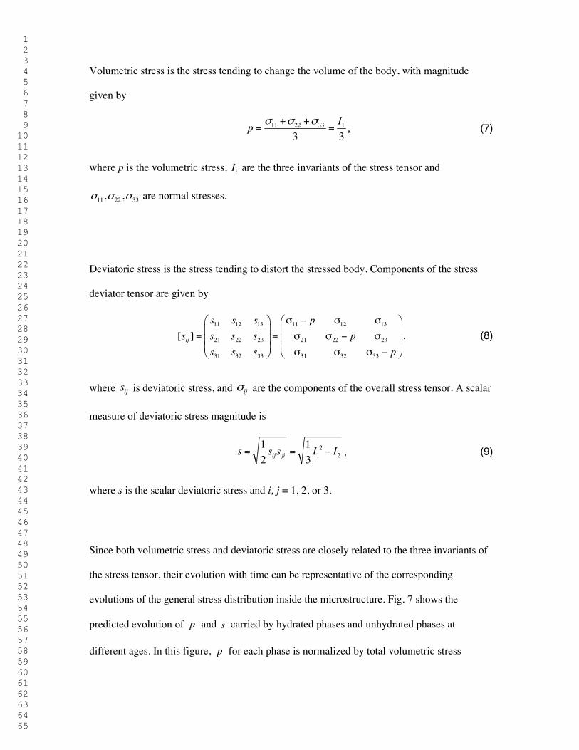
1 2 3 4 5 6 7 8 9 10 11 12 13 14 15 16 17 18 19 20 21 22 23 24 25 26 27 28 29 30 31 32 33 34 35 36 37 38 39 40 41 42 43 44 45 46 47 48 49 50 51 52 53 54 55 56 57 58 59 60 61 62 63 64 65
Volumetric stress is the stress tending to change the volume of the body, with magnitude
given by
11 22 33 1
3 3Ip σ σ σ+ +
= = , (7)
where p is the volumetric stress, iI are the three invariants of the stress tensor and
11 22 33, ,σ σ σ are normal stresses.
Deviatoric stress is the stress tending to distort the stressed body. Components of the stress
deviator tensor are given by
11 12 13 11 12 13
21 22 23 21 22 23
31 32 33 31 32 33
[ ]ij
s s s ps s s s p
s s s p
σ − σ σ = = σ σ − σ σ σ σ −
, (8)
where ijs is deviatoric stress, and ijσ are the components of the overall stress tensor. A scalar
measure of deviatoric stress magnitude is
21 2
1 12 3ij jis s s I I= = − , (9)
where s is the scalar deviatoric stress and i, j = 1, 2, or 3.
Since both volumetric stress and deviatoric stress are closely related to the three invariants of
the stress tensor, their evolution with time can be representative of the corresponding
evolutions of the general stress distribution inside the microstructure. Fig. 7 shows the
predicted evolution of p and s carried by hydrated phases and unhydrated phases at
different ages. In this figure, p for each phase is normalized by total volumetric stress
1 2 3 4 5 6 7 8 9 10 11 12 13 14 15 16 17 18 19 20 21 22 23 24 25 26 27 28 29 30 31 32 33 34 35 36 37 38 39 40 41 42 43 44 45 46 47 48 49 50 51 52 53 54 55 56 57 58 59 60 61 62 63 64 65
carried by the whole microstructure and s for each phase is normalized by total deviatoric
stress carried by the whole microstructure. The normalization is expressed according to
/ ( )( )
( )hydrated unhydrated
N
tt
tσ
σσ =
< >∑ (10)
where ( )Ntσ is either normalized volumetric or deviatoric stress at time t,
/ ( )hydrated unhydrated tσ∑ is the summed volumetric or deviatoric stress over hydrated or
unhydrated voxels at time t, and ( )tσ< > is the integrated volumetric or deviatoric stress
over the whole volume of the microstructure at time t. Microstructures constructed
considering 0.40 w/c with pure elastic phases at different ages were utilized in the model, and
the elastic properties of all phases were taken from [1].
Fig. 7 Normalized volumetric stress and deviatoric stress carried by hydrated phases and unhydrated phases
inside cement paste microstructure under loading age of 1 d. The summed volumetric and deviatoric stresses
carried by hydrated phases and unhydrated phases at time t are normalized by total volumetric stress or total
deviatoric stress carried by the whole microstructure at time t, respectively.
As C-S-H creep and relaxation has historically been considered the dominant mechanism
leading to cement paste creep and relaxation, some constitutive models, such as the
solidification theory [39], have been developed based on this understanding. Although the
solidification theory appears to have been developed with a uniaxial stress state in mind [40],
under any specific boundary conditions, evolutions of volumetric stress and deviatoric stress
with time should all be capable of representing the general stress evolutions inside the
microstructure, as discussed in previous paragraphs of this section. Due to equilibrium

1 2 3 4 5 6 7 8 9 10 11 12 13 14 15 16 17 18 19 20 21 22 23 24 25 26 27 28 29 30 31 32 33 34 35 36 37 38 39 40 41 42 43 44 45 46 47 48 49 50 51 52 53 54 55 56 57 58 59 60 61 62 63 64 65
requirements, the normalized, spatially averaged stress carried by the solidified products
(equivalent to hydration products) in the solidification theory may be calculated through
( )( )( )
total ttt
σσ =
ν (11)
where ( )tν is the aging function describing the volume fraction of solidified phases, and
( )total tσ is the normalized total stress, either volumetric stress or deviatoric stress, predicted
by the present model. Note that the solidification theory does not allow for any stress being
carried by the unhydrated cement, even after the cement paste has set. From a simple
composite theory view, it is clear that if solid phases are connected to the main solid
backbone, they will carry load. Computations have shown that at lower values of w/c, the
effective elastic moduli are significantly affected by the unhydrated cement [1].
For comparison purposes, the curves of normalized stresses carried by solidified phases
calculated via the new model presented in this paper are obtained by summing all normalized
stresses carried by the phases that solidify after load is applied. The evolution of stresses
carried by the hydration products after the application of load (at age of 1 d) as predicted by
the solidification theory and the new model are shown together in Fig. 8. The predictions
considered a 0.40 w/c cement paste hydrating under isothermal conditions (25° C).
Fig. 8 Comparison between the new model developed herein and the solidification theory regarding normalized
(a) volumetric and (b) deviatoric stress carried by solidified phases (hydration products). The stresses are
normalized by instantaneous total stress carried by the microstructure.

1 2 3 4 5 6 7 8 9 10 11 12 13 14 15 16 17 18 19 20 21 22 23 24 25 26 27 28 29 30 31 32 33 34 35 36 37 38 39 40 41 42 43 44 45 46 47 48 49 50 51 52 53 54 55 56 57 58 59 60 61 62 63 64 65
The solidification theory predicts that the average stress carried by solidified or hydrated
phases decreases with time, which results from the presumption that only solidified phases
may transmit stress. The solidification theory implies that hydration products are non-aging
viscoelastic materials and aging arises in the bulk scale due to the increase in load bearing
materials as a result of solidification and deposition of hydration products. As hydration
progresses, each newly formed layer of the hydration products solidifies in a stress-free state
and these layers are only subject to loads after they form. As a result of the predicted decrease
in stress carried by solidified phases (including C-S-H) as hydration progresses, the
solidification theory can account for the early-age aging effect through reduced C-S-H creep
as stress in that phase decreases. However, according to the model developed herein and as
shown in Fig. 7, the total stress carried by solidified phases increases with age. This increase
occurs because the new model accounts for the fact that stress may be transmitted by both
hydrated and unhydrated phases (hydrostatic stresses may be transmitted by cement grains at
any age, while deviatoric stresses may only be transmitted once percolation of the solid
skeleton has occurred). Since unhydrated phases are allowed to carry stress, their dissolution
results in an increase in stress on hydration products. Thus, the solidification theory is only
able to capture early-age aging effects while considering C-S-H viscoelasticity as a primary
mechanism for early-age cement paste creep and relaxation because the ability of cement
grains to transmit stress is neglected.
4. Conclusions
A computational scheme that couples a microstructure evolution model and a time-stepping
finite element method capable of tracking phase formation is developed in this paper to
predict the apparent VE/VP properties of cement paste as a function of time-evolving

1 2 3 4 5 6 7 8 9 10 11 12 13 14 15 16 17 18 19 20 21 22 23 24 25 26 27 28 29 30 31 32 33 34 35 36 37 38 39 40 41 42 43 44 45 46 47 48 49 50 51 52 53 54 55 56 57 58 59 60 61 62 63 64 65
microstructures. From the model simulations, the apparent VE/VP behavior of hydrating
cement paste due to dissolution of cement grains is a significant factor in the overall early-age
creep and relaxation of the paste. The main reasons behind this are the stress transmission from
dissolved load bearing phases to surrounding hydrated phases or cement grains, and the
generation of apparent strain in the new components that form in deformed configurations
(i.e., the newly formed phases have a deformation gradient but no stress). Simulation results
also indicate that intrinsic C-S-H viscoelasticity is not likely the primary mechanism leading
to the early-age creep and relaxation behavior of cementitious materials; this is because
significant C-S-H relaxation results in simulated macroscopic behavior that is in conflict with
experimental evidence of early-age aging effects.
The comparison between the evolution of stresses within hydration products predicted by the
new computational scheme and that predicted by the solidification theory indicates that the
specific assumption made about the extent to which unhydrated phases can transmit stress is
key to interpreting VE/VP mechanisms of cement paste. If one stipulates that unhydrated
phases do not carry stress (as with the solidification theory), then increased formation of C-S-
H can lead to aging of VE/VP properties of cement paste (e.g., reductions in creep or
relaxation rates at later ages). However, as demonstrated by the new computational scheme
and model presented herein, if one presumes that unhydrated phases may transmit stress once
the solid phases form a percolated network, then their dissolution results in an increase in
stress on hydration products as hydration progresses. This increase in stress in the less stiff
hydration products results in a greater relaxation rate, counteracting any reduction in rate due
to the increased formation of C-S-H; thus, the formation of C-S-H does not act as a source of
aging of VE/VP properties of cement paste. Conversely, the slowing of the cement

1 2 3 4 5 6 7 8 9 10 11 12 13 14 15 16 17 18 19 20 21 22 23 24 25 26 27 28 29 30 31 32 33 34 35 36 37 38 39 40 41 42 43 44 45 46 47 48 49 50 51 52 53 54 55 56 57 58 59 60 61 62 63 64 65
dissolution process (associated with the hydration reaction) with time may lead to lower
creep and relaxation rates of cement paste at later ages, contributing strongly to the early age
aging of cement paste.
The model discussed in this paper is yet unable to fully explain certain observed VE/VP
behavior of cement paste, including overall observed magnitude and differences between
responses associated with tensile and compressive stresses. Thus, additional mechanisms
must be considered in addition to hydration induced cement grain dissolution.
Acknowledgments
This research was supported by the National Science Foundation CAREER Award Program
under grant numbers 0843979 and 1327314. Any opinions, findings, and conclusions or
recommendations expressed in this material are those of the author(s) and do not necessarily
reflect the views of the National Science Foundation.
References
[1] Haecker CJ, Garboczi EJ, Bullard JW, Bohn RB, Sun Z, Shah SP, et al. Modeling the
linear elastic properties of Portland cement paste. Cement and Concrete Research.
2005;35(10):1948-60.
[2] Mindess S, Young JF, Darwin D. Concrete. 2nd ed. Upper Saddle River, NJ: Prentice
Hall; 2002.
[3] Tamtsia BT, Beaudoin JJ. Basic creep of hardened cement paste A re-examination of the
role of water. Cement and Concrete Research. 2000;30(9):1465-75.

1 2 3 4 5 6 7 8 9 10 11 12 13 14 15 16 17 18 19 20 21 22 23 24 25 26 27 28 29 30 31 32 33 34 35 36 37 38 39 40 41 42 43 44 45 46 47 48 49 50 51 52 53 54 55 56 57 58 59 60 61 62 63 64 65
[4] Powers TC. Mechanisms of shrinkage and reversible creep of hardened portland cement
paste Proceedings of International Conference On the Structure of Concrete. London,
England: Cement and Concrete Association; 1968.
[5] Ruetz W. A hypothesis for the creep of hardened cement paste and the influence of
simultaneous shrinkage Proceedings of International Conference On the Structure of
Concrete. London, England: Cement and Concrete Association; 1968.
[6] Leung CK, Grasley ZC. Poromechanical damping of cementitious materials. Journal of
Materials in Civil Engineering. 2012;24(2):232-8.
[7] Grasley ZC, Leung CK. Desiccation shrinkage of cementitious materials as an aging,
poroviscoelastic response. Cement and Concrete Research. 2011;41(1):77-89.
[8] Grasley ZC, Scherer GW, Lange DA, Valenza JJ. Dynamic pressurization method for
measuring permeability and modulus: II. cementitious materials. Materials and Structures.
2007;40(7):711-21.
[9] Coussy O, Monteiro PJM. Poroelastic model for concrete exposed to freezing
temperatures. Cement and Concrete Research. 2008;38(1):40-8.
[10] Scherer GW. Characterization of saturated porous bodies. Materials and
Structures/Materiaux et Constructions. 2004;37(265):21-30.
[11] Ulm FJ, Constantinides G, Heukamp FH. Is concrete a poromechanics material? - A
multiscale investigation of poroelastic properties. Materials and Structures/Materiaux et
Constructions. 2004;37(265):43-58.
[12] Suter M, Benipal G. Constitutive model for aging thermoviscoelasticity of reacting
concrete I: theoretical formulation. Mechanics of Time-Dependent Materials.
2010;14(3):277-90.
[13] Jensen M, Hansen PF. Autogenous deformation and change of the relative humidity in
silica fume-modified cement paste. ACI Materials Jounal. 1996;93(6):539-43.

1 2 3 4 5 6 7 8 9 10 11 12 13 14 15 16 17 18 19 20 21 22 23 24 25 26 27 28 29 30 31 32 33 34 35 36 37 38 39 40 41 42 43 44 45 46 47 48 49 50 51 52 53 54 55 56 57 58 59 60 61 62 63 64 65
[14] Jones CA, Grasley ZC. Correlation of hollow and solid cylinder dynamic pressurization
tests for measuring permeability. Cement and Concrete Research. 2009;39(4):345-52.
[15] Grasley Z, Scherer G, Lange D, Valenza J. Dynamic pressurization method for
measuring permeability and modulus: II. cementitious materials. Materials and Structures.
2007;40(7):711-21.
[16] Grasley ZC, Jones CA, Li X, Garboczi EJ, Bullard JW. Elastic and viscoelastic
properties of calcium silicate hydrate. NICOM 4: 4th International Symposium on
Nanotechnology in Consturction2012.
[17] Bentz DP. Quantitative comparison of real and CEMHYD3D model microstructures
using correlation functions. Cement and Concrete Research. 2006;36(2):259-63.
[18] Garboczi EJ. Finite element and finite difference programs for computing the linear
electric and elastic properties of digital images of random materials. Building and Fire
Research Laboratory,National Institute of Standards and Technology; 1998.
[19] Bohn RB, Garboczi EJ. User manual for finite element and finite difference programs: A
parallel version of NISTIR-6269. Gaithersburg: U.S. Department of commerce, Technology
Administration, National Institute of Standards and Technology, Information Technology
Laboratory, Building and Fire Research Labortory; 2003.
[20] Garboczi EJ, Day AR. An algorithm for computing the effective linear elastic properties
of heterogeneous materials: Three-dimensional results for composites with equal phase
poisson ratios. Journal of the Mechanics and Physics of Solids. 1995;43(9):1349-62.
[21] Bullard JW, Lothenbach B, Stutzman PE, Snyder KA. Coupling thermodynamics and
digital image models to simulate hydration and microstructure development of portland
cement pastes. Journal of Materials Research. 2011;26(4):609-22.
[22] Lothenbach B, Winnefeld F. Thermodynamic modelling of the hydration of portland
cement. Cement and Concrete Research. 2006;36(2):209-26.

1 2 3 4 5 6 7 8 9 10 11 12 13 14 15 16 17 18 19 20 21 22 23 24 25 26 27 28 29 30 31 32 33 34 35 36 37 38 39 40 41 42 43 44 45 46 47 48 49 50 51 52 53 54 55 56 57 58 59 60 61 62 63 64 65
[23] Kulik DA. Gibbs energy minimization approach to modeling sorption equilibria at the
mineral-water interface: Thermodynamic relations for multi-site-surface complexation.
American Journal of Science. 2002;302(3):227-79.
[24] Kulik DA. Dual-thermodynamic estimation of stoichiometry and stability of solid
solution end members in aqueous–solid solution systems. Chemical Geology. 2006;225(3–
4):189-212.
[25] Zohdi TI. Homogenization Methods and Multiscale Modeling. Encyclopedia of
Computational Mechanics: John Wiley & Sons, Ltd; 2004.
[26] Watt JP, Peselnick L. Clarification of the HashinϋShtrikman bounds on the effective
elastic moduli of polycrystals with hexagonal, trigonal, and tetragonal symmetries. Journal of
Applied Physics. 1980;51(3):1525 - 31.
[27] Kamali S, Moranville M, Garboczi E, Prené S, Gérard B. Influence of hydrate
dissolution by water on the Young’s modulus of cement-based materials. In: de Borst MP-C,
van Mier, Balkema, editor. FRAMCOS-5. Vail, CO, USA April 11, 2004.
[28] Bower AF. Applied mechanics of solids. Brown University, Providence, Rhode Island,
USA CRC Press; 1 edition 2009.
[29] Zienkiewicz OC, Taylor RL. Finite element method (5th edition) Volume 2 - solid
mechanics: Butterworth-Heinemann 2000; 2000.
[30] Lubliner J. Plasticity theory (revised edition). University of California at Berkeley:
Pearson Education, Inc.; 2008.
[31] Fung Y, Tong P. Classical and computational solid mechanics. Volume 1 of Advanced
series in engineering science: World Scientific Publishing Company; 2001.
[32] Timnoshenko SP, Goodier JN. Theory of elasticity. New York,: McGraw-Hill; 1970.
[33] Landau LD, Lifshitz EM. Theory of elasticity. 3rd ed. Oxford: Pergamon; 1986.

1 2 3 4 5 6 7 8 9 10 11 12 13 14 15 16 17 18 19 20 21 22 23 24 25 26 27 28 29 30 31 32 33 34 35 36 37 38 39 40 41 42 43 44 45 46 47 48 49 50 51 52 53 54 55 56 57 58 59 60 61 62 63 64 65
[34] Wineman AS, Rajagopal KR. Mechanical response of polymers: An introduction.
Cambridge, United Kingdom: Cambridge University Press 2000.
[35] Haupt RK. Explanation of final report on results of tests for portland cement proficiency
samples No.167 and No.168. Gaithersburg, Maryland: Cement and Concrete Reference
Laboratory; 2008.
[36] Jones CA, Grasley ZC. Short-term creep of cement paste during nanoindentation.
Cement and Concrete Composites. Cement and Concrete Composites. 2011;33(1):12-8.
[37] Vichit-Vadakan W, Scherer GW. Measuring permeability and stress relaxation of young
cement paste by beam bending. Cement and Concrete Research. 2003;33(12):1925-32.
[38] Pane I, Hansen W. Early age creep and stress relaxation of concrete containing blended
cements. Materials and Structures. 2002;35(2):92-6.
[39] Carol I, Bazant ZP. Viscoelasticity with aging caused by solidification of nonaging
constituent. Journal of Engineering Mechanics, ASCE. 1993;119(11):2252-69.
[40] Bazant ZP, Hauggard AB, Baweja S, Ulm FJ. Microprestress–solidification theory for
concrete creep: I. Aging and drying effects. Journal of Engineering Mechanics, ASCE.
1997;123(11):1188-94.