1 2 3 4 5 - miguelamartinezc.files.wordpress.com file1081 vw golf & jeta 2a chapter 2 part a:...
TRANSCRIPT

1081 VW Golf & Jeta
2A
Chapter 2 Part A:Engine repair procedures - 1.05 and 1.3 litre pre August 1985
GeneralType . . . . . . . . . . . . . . . . . . . . . . . . . . . . . . . . . . . . . . . . . . . . . . . . . . . . Four-cylinder in-line, water cooled, overhead camshaftCode:
1.05 litre . . . . . . . . . . . . . . . . . . . . . . . . . . . . . . . . . . . . . . . . . . . . . . . GN1.3 litre . . . . . . . . . . . . . . . . . . . . . . . . . . . . . . . . . . . . . . . . . . . . . . . . HK
Firing order . . . . . . . . . . . . . . . . . . . . . . . . . . . . . . . . . . . . . . . . . . . . . . . 1-3-4-2 (No 1 at camshaft sprocket end)Displacement:
1.05 litre . . . . . . . . . . . . . . . . . . . . . . . . . . . . . . . . . . . . . . . . . . . . . . . 1043 cc1.3 litre . . . . . . . . . . . . . . . . . . . . . . . . . . . . . . . . . . . . . . . . . . . . . . . . 1272 cc
Bore:1.05 litre . . . . . . . . . . . . . . . . . . . . . . . . . . . . . . . . . . . . . . . . . . . . . . . 75.0 mm1.3 litre . . . . . . . . . . . . . . . . . . . . . . . . . . . . . . . . . . . . . . . . . . . . . . . . 75.0 mm
Stroke:1.05 litre . . . . . . . . . . . . . . . . . . . . . . . . . . . . . . . . . . . . . . . . . . . . . . . 59.0 mm1.3 litre . . . . . . . . . . . . . . . . . . . . . . . . . . . . . . . . . . . . . . . . . . . . . . . . 72.0 mm
Compression ratio:1.05 litre . . . . . . . . . . . . . . . . . . . . . . . . . . . . . . . . . . . . . . . . . . . . . . . 9.5 to 11.3 litre . . . . . . . . . . . . . . . . . . . . . . . . . . . . . . . . . . . . . . . . . . . . . . . . 9.5 to 1
Compression pressure:New . . . . . . . . . . . . . . . . . . . . . . . . . . . . . . . . . . . . . . . . . . . . . . . . . . . 8 to 10 barMinimum . . . . . . . . . . . . . . . . . . . . . . . . . . . . . . . . . . . . . . . . . . . . . . . 7.0 barMaximum permissible difference between any two cylinders . . . . . . 3.0 bar
Camshaft - examination and renovation . . . . . . . . . . . . . . . . . . . . . . 27Camshaft - refitting . . . . . . . . . . . . . . . . . . . . . . . . . . . . . . . . . . . . . . 35Camshaft - removal . . . . . . . . . . . . . . . . . . . . . . . . . . . . . . . . . . . . . . 10Crankshaft and bearings - examination and renovation . . . . . . . . . . 21Crankshaft and main bearings - refitting . . . . . . . . . . . . . . . . . . . . . . 29Crankshaft and main bearings - removal . . . . . . . . . . . . . . . . . . . . . 18Crankshaft oil seals - renewal . . . . . . . . . . . . . . . . . . . . . . . . . . . . . . 14Cylinder block/crankcase - examination and renovation . . . . . . . . . 22Cylinder head - dismantling and overhaul . . . . . . . . . . . . . . . . . . . . . 11Cylinder head - reassembly . . . . . . . . . . . . . . . . . . . . . . . . . . . . . . . . 34Cylinder head - refitting . . . . . . . . . . . . . . . . . . . . . . . . . . . . . . . . . . . 36Cylinder head - removal . . . . . . . . . . . . . . . . . . . . . . . . . . . . . . . . . . 9Engine dismantling - general information . . . . . . . . . . . . . . . . . . . . . 7Engine reassembly - general information . . . . . . . . . . . . . . . . . . . . . 28Engine - adjustments after major overhaul . . . . . . . . . . . . . . . . . . . . 41Engine ancillary components - removal . . . . . . . . . . . . . . . . . . . . . . 8Engine ancillary components and gearbox - refitting . . . . . . . . . . . . 39Engine - refitting . . . . . . . . . . . . . . . . . . . . . . . . . . . . . . . . . . . . . . . . 40Engine - removal . . . . . . . . . . . . . . . . . . . . . . . . . . . . . . . . . . . . . . . . 5Engine/gearbox - separation . . . . . . . . . . . . . . . . . . . . . . . . . . . . . . . 6Examination and renovation - general information . . . . . . . . . . . . . . 20
Flywheel - examination and renovation . . . . . . . . . . . . . . . . . . . . . . . 25Flywheel - refitting . . . . . . . . . . . . . . . . . . . . . . . . . . . . . . . . . . . . . . . 33Flywheel - removal . . . . . . . . . . . . . . . . . . . . . . . . . . . . . . . . . . . . . . . 13General information . . . . . . . . . . . . . . . . . . . . . . . . . . . . . . . . . . . . . . 1Major operation only possible after removal of engine from vehicle . . 3Major operations possible with engine in vehicle . . . . . . . . . . . . . . . 2Method of engine removal . . . . . . . . . . . . . . . . . . . . . . . . . . . . . . . . . 4Oil filter - renewal . . . . . . . . . . . . . . . . . . . . . . . . . . . . . . . . . . . . . . . . 19Oil pump - examination and renovation . . . . . . . . . . . . . . . . . . . . . . 24Oil pump - refitting . . . . . . . . . . . . . . . . . . . . . . . . . . . . . . . . . . . . . . . 31Oil pump - removal . . . . . . . . . . . . . . . . . . . . . . . . . . . . . . . . . . . . . . 16Pistons and connecting rods - examination and renovation . . . . . . . 23Pistons and connecting rods - refitting . . . . . . . . . . . . . . . . . . . . . . . 30Pistons and connecting rods - removal . . . . . . . . . . . . . . . . . . . . . . . 17Sump - refitting . . . . . . . . . . . . . . . . . . . . . . . . . . . . . . . . . . . . . . . . . 32Sump - removal . . . . . . . . . . . . . . . . . . . . . . . . . . . . . . . . . . . . . . . . ..15Timing belt and sprockets - examination and renovation . . . . . . . . . 26Timing belt and sprockets - refitting . . . . . . . . . . . . . . . . . . . . . . . . . 37Timing belt and sprockets - removal . . . . . . . . . . . . . . . . . . . . . . . . . 12Valve clearances - checking and adjustment . . . . . . . . . . . . . . . . . . 38
2A•1
Specifications
Contents
Easy, suitable fornovice with littleexperience
Fairly easy, suitablefor beginner withsome experience
Fairly difficult,suitable for competentDIY mechanic
Difficult, suitable forexperienced DIYmechanic
Very difficult,suitable for expert DIYor professional
Degrees of difficulty
54321

CrankshaftMain journal:
Standard diameter . . . . . . . . . . . . . . . . . . . . . . . . . . . . . . . . . . . . . . . 54.0 mmUndersizes . . . . . . . . . . . . . . . . . . . . . . . . . . . . . . . . . . . . . . . . . . . . . 53.75, 53.50 and 53.25 mm
Crankpin:Standard diameter . . . . . . . . . . . . . . . . . . . . . . . . . . . . . . . . . . . . . . . 42 mmJournal undersizes . . . . . . . . . . . . . . . . . . . . . . . . . . . . . . . . . . . . . . . 41.75, 41.50 and 41.25 mm
Endfloat:Maximum . . . . . . . . . . . . . . . . . . . . . . . . . . . . . . . . . . . . . . . . . . . . . . 0.20 mmMinimum . . . . . . . . . . . . . . . . . . . . . . . . . . . . . . . . . . . . . . . . . . . . . . . 0.07 mm
Main bearing maximum running clearance . . . . . . . . . . . . . . . . . . . . . . 0.17 mm
Connecting rodsBig-end:
Maximum running clearance . . . . . . . . . . . . . . . . . . . . . . . . . . . . . . . . 0.095 mmMaximum endfloat . . . . . . . . . . . . . . . . . . . . . . . . . . . . . . . . . . . . . . . 0.40 mm
PistonsClearance in bore:
Maximum . . . . . . . . . . . . . . . . . . . . . . . . . . . . . . . . . . . . . . . . . . . . . . 0.07 mmMinimum . . . . . . . . . . . . . . . . . . . . . . . . . . . . . . . . . . . . . . . . . . . . . . . 0.03 mm
Diameter:Standard . . . . . . . . . . . . . . . . . . . . . . . . . . . . . . . . . . . . . . . . . . . . . . . 74.98 mmOversize:
1st oversize . . . . . . . . . . . . . . . . . . . . . . . . . . . . . . . . . . . . . . . . . . . 75.23 mm2nd oversize . . . . . . . . . . . . . . . . . . . . . . . . . . . . . . . . . . . . . . . . . . 75.48 mm3rd oversize . . . . . . . . . . . . . . . . . . . . . . . . . . . . . . . . . . . . . . . . . . . 75.98 mm
Wear limit (10 mm from base/ right angles to pin) . . . . . . . . . . . . . . . . . 0.04 mm
Piston ringsMaximum clearance in groove. . . . . . . . . . . . . . . . . . . . . . . . . . . . . . . . 0.15 mmEnd gap:
Compression rings . . . . . . . . . . . . . . . . . . . . . . . . . . . . . . . . . . . . . . . 0.30 to 0.45 mmOil scraper ring . . . . . . . . . . . . . . . . . . . . . . . . . . . . . . . . . . . . . . . . . . 0.25 to 0.40 mm
Gudgeon pinFit in piston . . . . . . . . . . . . . . . . . . . . . . . . . . . . . . . . . . . . . . . . . . . . . . . Push fit at 60°C
Cylinder headMaximum allowable face distortion . . . . . . . . . . . . . . . . . . . . . . . . . . . . 0.1 mm
CamshaftRun-out at centre bearing . . . . . . . . . . . . . . . . . . . . . . . . . . . . . . . . . . . . 0.02 mmEndfloat . . . . . . . . . . . . . . . . . . . . . . . . . . . . . . . . . . . . . . . . . . . . . . . . . . 0.15 mm
ValvesSeat angle . . . . . . . . . . . . . . . . . . . . . . . . . . . . . . . . . . . . . . . . . . . . . . . . 45°Head diameter:
Inlet . . . . . . . . . . . . . . . . . . . . . . . . . . . . . . . . . . . . . . . . . . . . . . . . . . . 34.0 mmExhaust . . . . . . . . . . . . . . . . . . . . . . . . . . . . . . . . . . . . . . . . . . . . . . . . 28.1 mm
Stem diameter:Inlet . . . . . . . . . . . . . . . . . . . . . . . . . . . . . . . . . . . . . . . . . . . . . . . . . . . 7.97 mmExhaust . . . . . . . . . . . . . . . . . . . . . . . . . . . . . . . . . . . . . . . . . . . . . . . . 7.95 mm
Standard overall length:Inlet . . . . . . . . . . . . . . . . . . . . . . . . . . . . . . . . . . . . . . . . . . . . . . . . . . . 110.5 mmExhaust . . . . . . . . . . . . . . . . . . . . . . . . . . . . . . . . . . . . . . . . . . . . . . . . 110.5 mm
Valve guidesMaximum valve rock (stem flush with guide):
Inlet . . . . . . . . . . . . . . . . . . . . . . . . . . . . . . . . . . . . . . . . . . . . . . . . . . . 1.0 mmExhaust . . . . . . . . . . . . . . . . . . . . . . . . . . . . . . . . . . . . . . . . . . . . . . . . 1.3 mm
Valve timingNil valve clearance at 1.0 mm valve lift1.05 litre:
Inlet opens . . . . . . . . . . . . . . . . . . . . . . . . . . . . . . . . . . . . . . . . . . . . . 9° ATDCInlet closes . . . . . . . . . . . . . . . . . . . . . . . . . . . . . . . . . . . . . . . . . . . . . 13° ABDCExhaust opens . . . . . . . . . . . . . . . . . . . . . . . . . . . . . . . . . . . . . . . . . . 15° BBDCExhaust closes . . . . . . . . . . . . . . . . . . . . . . . . . . . . . . . . . . . . . . . . . . 11° BTDC
2A•2 Engine repair procedures - 1.05 and 1.3 litre pre August 1985
1081 VW Golf & Jeta

1.3 litre:Inlet opens . . . . . . . . . . . . . . . . . . . . . . . . . . . . . . . . . . . . . . . . . . . . . 3° BTDCInlet closes . . . . . . . . . . . . . . . . . . . . . . . . . . . . . . . . . . . . . . . . . . . . . 38° ABDCExhaust opens . . . . . . . . . . . . . . . . . . . . . . . . . . . . . . . . . . . . . . . . . . 41° BBDCExhaust closes . . . . . . . . . . . . . . . . . . . . . . . . . . . . . . . . . . . . . . . . . . 3° BTDC
Valve clearancesWarm:
Inlet . . . . . . . . . . . . . . . . . . . . . . . . . . . . . . . . . . . . . . . . . . . . . . . . . . . 0.15 to 0.20 mmExhaust . . . . . . . . . . . . . . . . . . . . . . . . . . . . . . . . . . . . . . . . . . . . . . . . 0.25 to 0.30 mm
Cold:Inlet . . . . . . . . . . . . . . . . . . . . . . . . . . . . . . . . . . . . . . . . . . . . . . . . . . . 0.10 to 0.15 mmExhaust . . . . . . . . . . . . . . . . . . . . . . . . . . . . . . . . . . . . . . . . . . . . . . . . 0.20 to 0.25 mm
LubricationSystem type . . . . . . . . . . . . . . . . . . . . . . . . . . . . . . . . . . . . . . . . . . . . . . Wet sump, pressure feed, full flow filterLubricant type/specification/capacity . . . . . . . . . . . . . . . . . . . . . . . . . . Refer to “Lubricants, fluids and capacities”Filter type . . . . . . . . . . . . . . . . . . . . . . . . . . . . . . . . . . . . . . . . . . . . . . . . Champion C101/C160 Pump type . . . . . . . . . . . . . . . . . . . . . . . . . . . . . . . . . . . . . . . . . . . . . . . Eccentric gear driven by crankshaftPressure (2000 rpm with oil temperature 80°C) . . . . . . . . . . . . . . . . . . . 2.0 bar minimum
Torque wrench settings Nm lbf ftEngine to gearbox . . . . . . . . . . . . . . . . . . . . . . . . . . . . . . . . . . . . . . . . . 55 41Exhaust pipe to manifold . . . . . . . . . . . . . . . . . . . . . . . . . . . . . . . . . . . . 25 18Flywheel bolts . . . . . . . . . . . . . . . . . . . . . . . . . . . . . . . . . . . . . . . . . . . . . 75 55Clutch bolts . . . . . . . . . . . . . . . . . . . . . . . . . . . . . . . . . . . . . . . . . . . . . . 25 18Sump bolts . . . . . . . . . . . . . . . . . . . . . . . . . . . . . . . . . . . . . . . . . . . . . . . 20 15Sump drain plug . . . . . . . . . . . . . . . . . . . . . . . . . . . . . . . . . . . . . . . . . . . 30 22Main bearing cap bolts . . . . . . . . . . . . . . . . . . . . . . . . . . . . . . . . . . . . . . 65 48Oil pump bolts . . . . . . . . . . . . . . . . . . . . . . . . . . . . . . . . . . . . . . . . . . . . 10 7Connecting rod big-end cap nuts (oiled):
Stage 1 . . . . . . . . . . . . . . . . . . . . . . . . . . . . . . . . . . . . . . . . . . . . . . . . 30 22Stage 2* . . . . . . . . . . . . . . . . . . . . . . . . . . . . . . . . . . . . . . . . . . . . . . . Tighten further 1/4 turn (90°)
Oil suction pipe to pump . . . . . . . . . . . . . . . . . . . . . . . . . . . . . . . . . . . . 10 7Oil relief valve plug . . . . . . . . . . . . . . . . . . . . . . . . . . . . . . . . . . . . . . . . . 25 18Oil pressure sender switch . . . . . . . . . . . . . . . . . . . . . . . . . . . . . . . . . . . 25 18Timing cover . . . . . . . . . . . . . . . . . . . . . . . . . . . . . . . . . . . . . . . . . . . . . . 10 7Valve cover . . . . . . . . . . . . . . . . . . . . . . . . . . . . . . . . . . . . . . . . . . . . . . . 10 7Camshaft sprocket bolt . . . . . . . . . . . . . . . . . . . . . . . . . . . . . . . . . . . . . 80 59Crankshaft sprocket/pulley nut . . . . . . . . . . . . . . . . . . . . . . . . . . . . . . . 80 59Coolant pump bolts . . . . . . . . . . . . . . . . . . . . . . . . . . . . . . . . . . . . . . . . 10 7Distributor flange bolts . . . . . . . . . . . . . . . . . . . . . . . . . . . . . . . . . . . . . . 20 15Cylinder head bolts (engine cold):
Stage 1 . . . . . . . . . . . . . . . . . . . . . . . . . . . . . . . . . . . . . . . . . . . . . . . . 40 30Stage 2 . . . . . . . . . . . . . . . . . . . . . . . . . . . . . . . . . . . . . . . . . . . . . . . . 60 44Stage 3 . . . . . . . . . . . . . . . . . . . . . . . . . . . . . . . . . . . . . . . . . . . . . . . . Tighten further 1/2 turn (180°)
Engine mountings (with oiled threads):Refer to illustrations 40.1a and 40.1b
(a) M8 . . . . . . . . . . . . . . . . . . . . . . . . . . . . . . . . . . . . . . . . . . . . . . . . . 25 18(a) M10 . . . . . . . . . . . . . . . . . . . . . . . . . . . . . . . . . . . . . . . . . . . . . . . . 45 33(b) . . . . . . . . . . . . . . . . . . . . . . . . . . . . . . . . . . . . . . . . . . . . . . . . . . . . 35 26(c) . . . . . . . . . . . . . . . . . . . . . . . . . . . . . . . . . . . . . . . . . . . . . . . . . . . . 45 33(d) . . . . . . . . . . . . . . . . . . . . . . . . . . . . . . . . . . . . . . . . . . . . . . . . . . . . 50 37(e) . . . . . . . . . . . . . . . . . . . . . . . . . . . . . . . . . . . . . . . . . . . . . . . . . . . . 60 44(f) . . . . . . . . . . . . . . . . . . . . . . . . . . . . . . . . . . . . . . . . . . . . . . . . . . . . 70 52(g) . . . . . . . . . . . . . . . . . . . . . . . . . . . . . . . . . . . . . . . . . . . . . . . . . . . . 80 59
* When checking the connecting rod-to-crankshaft journal radial clearance using Plastigage, tighten only to 30Nm (22 lbf ft).
Engine repair procedures - 1.05 and 1.3 litre pre August 1985 2A•3
2A
1081 VW Golf & Jeta
1 General information
The 1.05 and 1.3 litre engines are offour-cylinder, in-line, overhead camshaft type,mounted transversely at the front of thevehicle. The transmission is attached to theleft-hand side of the engine.
The crankshaft is of five bearing type andseparate thrustwashers are fitted to thecentral main bearing to control crankshaftendfloat.
The camshaft is driven by a toothed beltwhich also drives the coolant pump. Thetoothed belt is tensioned by moving the coolantpump in its eccentric mounting. The valves areoperated from the camshaft by rocker fingerswhich pivot on ball-head studs. The distributor
is driven by the camshaft and is located on theleft-hand end of the cylinder head.
The oil pump is of the eccentric gear typedriven from the end of the crankshaft.
The cylinder head is of crossflow design,with the inlet manifold at the rear and theexhaust manifold at the front.
The crankcase ventilation system is of thepositive type and consists of an oil separatoron the rear (coolant pipe side) of the cylinder
block, connected to the air cleaner by arubber hose. Vacuum from the air cleanerprovides a partial vacuum in the crankcaseand the piston blow-by gases are drawnthrough the oil separator and into the enginecombustion chambers.
2 Major operations possiblewith engine in vehicle
The following operations can be carried outwithout having to remove the engine from thevehicle:a) Removal and servicing of the cylinder
head, camshaft and timing beltb) Removal of the flywheel and crankshaft
rear oil seal (after removal of the gearbox)c) Removal of the sumpd) Removal of the piston/connecting rod
assemblies (after removal of the cylinderhead and sump)
e) Renewal of the crankshaft front and rearoil seals and the camshaft front oil seal
f) Renewal of the engine mountingsg) Removal of the oil pump
3 Major operation onlypossible after removal ofengine from vehicle
The following operation can only be carriedout after removal of the engine from the vehicle:a) Renewal of crankshaft main bearings
4 Method of engine removal
1 The engine, together with the gearbox,must be lifted from the engine compartmentand the engine separated from the gearboxon the bench. Two people will be needed.
2 A hoist of 150 kg capacity will be needed tolift the engine approximately 1 metre. If thehoist is not portable, then sufficient roommust be left behind the vehicle to push it backout of the way so that the engine may belowered. Blocks will be needed to support theengine after removal.3 Ideally the vehicle should be over a pit. Ifthis is not possible then the body must besupported on axle stands (see “Jacking andvehicle support”) so that the front wheels maybe turned to undo the driveshaft nuts. Theleft-hand shaft is accessible from above butthe right-hand shaft must be undone fromunderneath. Removal of the gearshift linkagecan only be done from underneath, as canremoval of the exhaust pipe bracket. When alltasks are complete, lower the vehicle backonto its wheels.4 A set of splined keys will be required toremove and refit the socket-head bolts usedto secure certain items, such as the cylinderhead bolts.5 Draining of oil and coolant is best doneaway from the working area if possible. Thissaves the mess made by spilled oil in theplace where you must work.6 If an air conditioning system is fitted,observe the precautions listed in Chapter 3.
5 Engine - removal 41 Disconnect the battery negative lead.2 Remove the bonnet.3 Drain the engine coolant and remove theradiator, complete with cooling fan unit.4 Remove the air cleaner unit.5 Loosen the clip and disconnect the tophose from the thermostat housing.6 Place a container beneath the engine thenunscrew the sump drain plug and drain the oil- see Chapter 1. When complete, clean thedrain plug and washer and refit it to the sump.
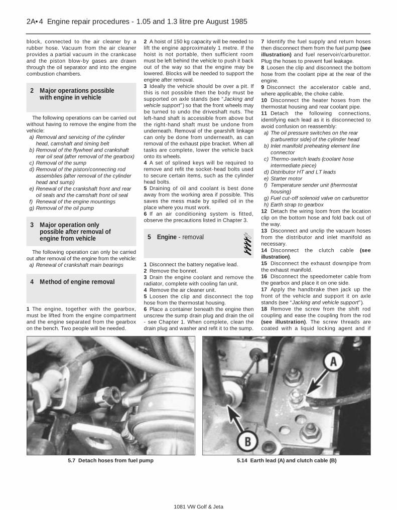
7 Identify the fuel supply and return hosesthen disconnect them from the fuel pump (seeillustration) and fuel reservoir/carburettor.Plug the hoses to prevent fuel leakage.8 Loosen the clip and disconnect the bottomhose from the coolant pipe at the rear of theengine.9 Disconnect the accelerator cable and,where applicable, the choke cable.10 Disconnect the heater hoses from thethermostat housing and rear coolant pipe.11 Detach the following connections,identifying each lead as it is disconnected toavoid confusion on reassembly:a) The oil pressure switches on the rear
(carburettor side) of the cylinder headb) Inlet manifold preheating element line
connectorc) Thermo-switch leads (coolant hose
intermediate piece) d) Distributor HT and LT leadse) Starter motorf) Temperature sender unit (thermostat
housing) g) Fuel cut-off solenoid valve on carburettorh) Earth strap to gearbox
12 Detach the wiring loom from the locationclip on the bottom hose and fold back out ofthe way.13 Disconnect and unclip the vacuum hosesfrom the distributor and inlet manifold asnecessary.14 Disconnect the clutch cable (seeillustration). 15 Disconnect the exhaust downpipe fromthe exhaust manifold.16 Disconnect the speedometer cable fromthe gearbox and place it on one side.17 Apply the handbrake then jack up thefront of the vehicle and support it on axlestands (see “Jacking and vehicle support”).18 Remove the screw from the shift rodcoupling and ease the coupling from the rod(see illustration). The screw threads arecoated with a liquid locking agent and if
2A•4 Engine repair procedures - 1.05 and 1.3 litre pre August 1985
1081 VW Golf & Jeta
5.7 Detach hoses from fuel pump 5.14 Earth lead (A) and clutch cable (B)

difficulty is experienced, it may be necessaryto heat up the coupling with a blowlamp whilstobserving the necessary fire precautions.Note that once removed this screw should berenewed.19 Note its orientation then withdraw the shiftrod coupling.20 Unbolt the exhaust steady bracket fromthe downpipe and clutch housing/startermotor.21 Detach the reversing light switch lead(see illustration).22 Unbolt the driveshafts from the driveflanges and tie them to one side with wire.23 Attach a suitable hoist to the engine liftingeye brackets (one at each end of the cylinderhead on the carburettor side) (seeillustration). Take the weight of theengine/gearbox unit.24 Working from above, undo the threeengine mounting/bearer retaining bolts(underneath the carburettor) (see illustration).25 Undo and remove the gearbox mountingbolt (rear left side of engine compartment).26 Undo and remove the front enginemounting bolt and then remove the boltssecuring the bracket to the engine. Withdrawthe mounting (see illustrations).
27 Before lifting out the engine/gearbox unit,get an assistant to hold the engine steady andhelp guide it clear of surrounding componentsas it is removed.28 Lift the engine/gearbox unit from theengine compartment (see illustration) whileturning it as necessary to clear the internallymounted components. Make sure that allwires, cables and hoses have beendisconnected.29 Lower the unit onto a workbench or largepiece of wood placed on the floor.
6 Engine/gearbox - separation 31 The engine/gearbox unit must besupported so that the gearbox can be easedaway from it. Either support the engine onblocks so that the gearbox overhangs thebench, or do the job while the engine andgearbox are on the hoist.2 Detach the lead from the alternator thenunclip the lead from the locating clips on thesump side walls.
Engine repair procedures - 1.05 and 1.3 litre pre August 1985 2A•5
2A
5.18 Shift rod coupling screw 5.21 Reversing light switch 5.23 Engine lifting eye
5.24 Engine mounting/bearer - right-hand 5.26a Undo front mounting through-bolt
1081 VW Golf & Jeta
5.26b Unbolt and remove mounting unit 5.28 Lifting out engine/gearbox unit

3 Because the rear bearing of the starterarmature is in the bellhousing, it is necessaryto remove the starter before separating theengine and gearbox. If not already removedwhen unbolting the starter motor, also detachthe exhaust pipe support bracket (seeillustration).4 Detach the coolant pipe at its flange on therear side of the coolant pump and at theclutch housing.5 Undo the clutch housing belly plate boltand withdraw the plate.6 Undo and remove the remainingengine-to-gearbox securing bolts then pull thegearbox free. Do not insert wedges or you willdamage the facing. Tap the gearbox gentlyand wriggle it off the two dowels which locateit. The intermediate plate will remain inposition (see illustrations).
7 Engine dismantling - generalinformation
1 If possible, mount the engine on a stand forthe dismantling procedure, but failing this,support it in an upright position with blocks ofwood.2 Cleanliness is most important. If the engineis dirty, it should be cleaned with paraffinwhile keeping it in an upright position.3 Avoid working with the engine directly on aconcrete floor as grit presents a real source oftrouble.4 As parts are removed, clean them in aparaffin bath. Do not immerse parts withinternal oilways in paraffin as it is difficult toremove. Clean oilways with nylon pipecleaners.5 Obtain suitable containers to hold smallitems. This will help when reassembling theengine and also prevent possible loss.6 Obtain complete sets of gaskets when theengine is being dismantled but retain the oldgaskets with a view to using them as a patternto make a replacement if a new one is notavailable.7 When possible, refit nuts, bolts andwashers in their location after being removed.This helps to protect the threads and will alsobe helpful when reassembling the engine.8 Retain unserviceable components in orderto compare them with the new parts supplied.
8 Engine ancillary components- removal 3
With the engine removed from the vehicleand separated from the gearbox, theexternally mounted ancillary componentsshould now be removed before dismantlingbegins. The removal sequence need notnecessarily follow the order given:a) Alternator and drivebeltb) Inlet manifold and carburettorc) Exhaust manifoldd) Distributore) Fuel pumpf) Thermostatg) Clutchh) Crankcase ventilation hosei) Distributor cap and spark plugsj) Oil filterk) Engine mountings (see illustrations)l) Dipstick (see illustration)m)Oil pressure switchesn) Coolant temperature thermo-switcho) Alternator mounting bracket and engine
earth leadp) Engine rear coolant pipe (see illustration)
2A•6 Engine repair procedures - 1.05 and 1.3 litre pre August 1985
6.3 Starter motor and exhaust supportbracket
6.6a Undo securing bolts (recessed boltshown) . . .
6.6b . . . then separate engine andtransmission
8.1b Right-hand rear mounting viewedfrom above
8.1a Lift the mounting away
8.1c Engine dipstick and tube 8.1d Removing engine rear coolant pipe
1081 VW Golf & Jeta

9 Cylinder head - removal 31 If the engine is still in the vehicle, first carryout the following operations:a) Disconnect the battery negative leadb) Remove the air cleaner and fuel pumpc) Drain the cooling system and remove the
top hose and thermostatd) Remove the distributor and spark plugse) Remove the inlet and exhaust manifolds.
If necessary, this can be carried out withthe cylinder head on the bench
f) Disconnect the wiring from the coolanttemperature sender and oil pressureswitch
2 Unscrew the nuts and bolts from the valvecover and remove the cover together with thegasket and reinforcement strips (seeillustrations).3 Turn the engine until the indentation in thecamshaft sprocket appears in the TDC hole inthe timing cover and the notch in thecrankshaft pulley is aligned with the TDCpointer on the front of the oil pump (seeillustrations). Now turn the crankshaft onequarter of a turn anti-clockwise so that noneof the pistons are at TDC.
4 Unbolt and remove the timing cover (seeillustration), noting that the dipstick tube andearth lead are fitted to the upper bolts. Onsome later 1.3 litre models, it is necessary toremove the crankshaft pulley to remove thelower timing belt cover. Pull the dipstick tubefrom the cylinder block.5 Using a socket through the hole in thecamshaft sprocket, unscrew the timing coverplate upper retaining bolt.6 Loosen the coolant pump retaining bolts,then turn the pump body clockwise to releasethe tension from the timing belt. Remove thetiming belt from the camshaft sprocket.
7 Remove the bolts and withdraw the timingcover plate, followed by the coolant pump ifrequired.8 Using a splined key, unscrew the cylinderhead bolts half a turn at a time in the reverseorder to that shown for tightening. Note thelocation of the engine lifting hooks. 9 Lift the cylinder head from the block (seeillustration). If it is stuck, tap it free with awooden mallet. Do not insert a lever asdamage will occur to the joint faces. 10 Remove the gasket from the cylinderblock (see illustration).
Engine repair procedures - 1.05 and 1.3 litre pre August 1985 2A•7
2A
9.2a Removing valve cover. . . 9.2b . . . and gasket
9.4 Removing timing cover 9.9 Removing cylinder head . . . 9.10 . . . and gasket
1081 VW Golf & Jeta
9.3a TDC mark on camshaft sprocket and pointer 9.3b Crankshaft pulley notch aligned with TDC pointer

10 Camshaft - removal 31 If the engine is still in the vehicle, first carryout the following operations:a) Disconnect the battery negative leadb) Remove the air cleaner and fuel pumpc) Remove the distributor and spark plugs
2 If the cylinder head is still fitted to theengine, first carry out the proceduredescribed in paragraphs 3 to 6 inclusive.3 Unscrew the nuts and bolts from the valvecover and remove the cover together with thegasket and reinforcement strips.4 Turn the engine until the indentation in thecamshaft sprocket appears in the TDC hole inthe timing cover and the notch in the
crankshaft pulley is aligned with the TDCpointer on the front of the oil pump. Now turnthe crankshaft one quarter of a turnanti-clockwise so that none of the pistons areat TDC.5 Unbolt and remove the timing cover, notingthat the dipstick tube and earth lead are fittedto the upper bolts. On some later 1.3 litremodels, it is necessary to remove thecrankshaft pulley to remove the lower timingbelt cover.6 Loosen the coolant pump retaining bolts,then turn the pump body clockwise to releasethe tension from the timing belt. Remove thetiming belt from the camshaft sprocket.7 Prise the oil spray tube from the top of thecylinder head (see illustration).8 Note how the cam follower clips are fittedthen prise them from the ball-studs (seeillustration).
9 Identify each cam follower for location thenremove each one by levering with ascrewdriver. Make sure that the peak of therelevant cam is pointing away from thefollower first by turning the camshaft asnecessary (see illustration).10 Unscrew the camshaft sprocket bolt andremove the spacer (see illustration). Thesprocket can be held stationary using a metalbar with two bolts, with one bolt inserted in ahole and the other bolt resting on the outer rimof the sprocket.11 Tap the sprocket from the camshaft with awooden mallet and prise out the Woodruffkey.12 Using feeler blades, check the camshaftendfloat by inserting the blade between theend of the camshaft and distributor flanges(see illustration). If it is more than the amountspecified, the components will have to bechecked for wear and renewed as necessary.13 Using an Allen key, unscrew the bolts andremove the distributor flange (seeillustration). Remove the gasket.14 Carefully slide the camshaft from thecylinder head, taking care not to damage thethree bearing surfaces as the lobes of thecams pass through them (see illustration).15 Prise the camshaft oil seal from thecylinder head (see illustration).
2A•8 Engine repair procedures - 1.05 and 1.3 litre pre August 1985
10.7 Removing oil spray tube 10.8 Removing a cam follower clip 10.9 Removing a cam follower
10.13 Removing distributor flange 10.14 Withdrawing camshaft
10.10 Removing camshaft sprocket bolt(early type sprocket shown)
10.12 Checking camshaft endfloat
10.15 Removing camshaft oil seal
1081 VW Golf & Jeta

11 Cylinder head - dismantlingand overhaul 3
Dismantling 1 Remove the cylinder head and camshaft, asdescribed in the previous Sections.2 Using a valve spring compressor, compresseach valve spring in turn until the split colletscan be removed. Release the compressor andremove the retainers and springs (seeillustrations). If the retainers are difficult toremove, do not continue to tighten thecompressor but gently tap the top of the toolwith a hammer. Always make sure that thecompressor is held firmly over the retainer.3 Remove each valve from the cylinder head,keeping them identified for location.4 Prise the valve seals from the valve guidesand remove the lower spring seats (seeillustration).5 Do not remove the cam follower ball-studsunless they are unserviceable. They are likelyto be seized in the head.
Overhaul6 Use a scraper to carefully remove anycarbon from the cylinder head. Remove alltraces of gasket then wash the cylinder headthoroughly in paraffin and wipe dry.7 Use a straight-edge and feeler blade tocheck that the cylinder head mating surface isnot distorted. If it is, then it must beresurfaced by a suitably equipped engineeringworks. If the cylinder head face is to beresurfaced, this will necessitate the valveseats being re-cut so that they are recesseddeeper by an equivalent amount to thatmachined from the cylinder head. This isnecessary to avoid the possibility of the valvescoming into contact with the pistons andcausing serious damage and is a task to beentrusted to a suitably equipped enginerecondition specialist. (see illustration).
8 Examine the valve heads for pitting andburning. Renew any valve which is badlyburnt. Examine the valve seats at the sametime. If the pitting is very slight, it can beremoved by grinding the valve heads andseats together with coarse, then fine, grindingpaste. Note that the exhaust valves should notbe re-cut, they should be renewed if thesealing face is excessively grooved as a resultof regrinding.9 Where excessive pitting has occurred, thevalve seats must be re-cut or renewed by aspecialist.10 Valve grinding is carried out as follows.Place the cylinder head upside down on abench with a block of wood at each end.Smear a trace of coarse carborundum pasteon the seat face and press a suction grindingtool onto the valve head. With a semi-rotaryaction, grind the valve head to its seat, liftingthe valve occasionally to redistribute thegrinding paste. When a dull matt even surfaceis produced on both the valve seat and thevalve, wipe off the paste and repeat theprocess with fine carborundum paste asbefore. A light spring placed under the valvehead will greatly ease this operation. When asmooth unbroken ring of light grey matt finishis produced on both the valve and seat, thegrinding operation is complete.
11 Scrape away all carbon from the valvehead stem and clean away all traces ofgrinding compound. Clean the valves andseats with a paraffin-soaked rag, then wipewith a clean rag.12 Check for wear in the valve guides. Thismay be detected by fitting a new valve in theguide and checking the amount that the rim ofthe valve will move sideways when the top ofthe valve stem is flush with the top of thevalve guide. The rock limit for the inlet valve is1.0 mm and 1.3 mm for the exhaust valve.This can be measured with feeler blades if youuse a clamp as a datum but it must be with anew valve. If the rock is at or below this limitwith your old valve then this indicates that theexisting guide(s) do not need renewal. Checkeach valve guide in turn but note that the inletand exhaust valve stem dimensions differ, sodo not get them confused. If the rock exceedsthe limit with a new valve, this will indicate theneed for new valve guides as well. Theremoval and refitting of new guides is a taskwhich must be entrusted to a specialist.
Engine repair procedures - 1.05 and 1.3 litre pre August 1985 2A•9
2A
11.4 . . . and valve spring lower seats
11.7 Measure cylinder head depthbetween points indicated
Minimum allowable depth a = 119.3 mm
1081 VW Golf & Jeta
11.2a Compressing a valve spring to remove split collets 11.2b Removing valve springs and retainers . . .

13 If possible, compare the length of thevalve springs with new ones and renew themas a set if any are shorter.14 If the engine is still in the vehicle, clean thepiston crowns and cylinder bore upper edgesbut make sure that no carbon drops betweenthe pistons and bores. To do this, locate twoof the pistons at the top of their bores andseal off the remaining bores with paper andmasking tape. Press a little grease betweenthe two pistons and their bores to collect anycarbon dust which can be wiped away whenthe piston is lowered. To prevent carbonbuild-up, polish the piston crown with metalpolish but remove all traces of the polishafterwards.
12 Timing belt and sprockets -removal 3
1 If the engine is still in the vehicle, first carryout the following operations:a) Disconnect the battery negative lead b) Remove the air cleaner c) Remove the alternator drivebelt
2 Turn the engine until the indentation in thecamshaft sprocket appears in the TDC hole inthe timing cover and the notch in thecrankshaft pulley is aligned with the TDCpointer on the front of the oil pump.3 Unbolt and remove the timing cover, notingthat the dipstick tube and earth lead are fittedto the upper bolts. On some later 1.3 litremodels, it is necessary to remove thecrankshaft pulley to remove the lower timingbelt cover.4 Loosen the coolant pump retaining bolts,then turn the pump body clockwise to releasethe tension from the timing belt. Remove thetiming belt from the camshaft sprocket (seeillustration).5 Using an Allen key, unbolt the pulley fromthe crankshaft sprocket then remove thetiming belt.6 To remove the camshaft sprocket, unscrewthe bolt and remove the spacer. Tap off thesprocket and remove the Woodruff key. Donot turn the camshaft. The sprocket can beheld stationary using a metal bar with twobolts, with one bolt inserted through a
sprocket hole and the other bolt resting on theouter rim.7 To remove the crankshaft sprocket,unscrew the bolt and lever the sprocket fromthe crankshaft (see illustration). Do not turnthe crankshaft otherwise the pistons maytouch the valve heads. Hold the crankshaftstationary with a lever inserted in the starterring gear (remove the starter as applicable).Remove the Woodruff key.
13 Flywheel - removal 31 Remove the clutch.2 Hold the flywheel stationary with a lever orangle iron (see illustration) engaged with thestarter ring gear.3 Unscrew the bolts and lift the flywheel fromthe crankshaft (see illustration).4 Remove the engine plate from the cylinderblock (see illustration). 5 The flywheel bolts must be renewed oncethey are removed.
14 Crankshaft oil seals - renewal 3Front seal1 Remove the crankshaft sprocket.2 If available, use VW tool 2085 to remove theseal from the oil pump housing. Removal of
the seal with the engine and oil pump inposition in the vehicle can prove difficultwithout the special tool. In this instance, analternative method is to drill two holes,diagonally opposed to each other in the seal,insert two self-tapping screws and then pullon the screws using grips to withdraw theseal. If using this method, care must be takennot to drill into the housing.3 If the oil pump is removed from the engine,the seal can be prised out and a new itemfitted - see illustration 31.1.4 Clean the recess in the oil pump.5 Smear a little clean engine oil on the lip andouter edge of the new seal, then fit it with VWtool 10-203 or by tapping it in with a suitablemetal tube .6 Refit the crankshaft sprocket.
Rear seal7 Remove the flywheel.
Method 18 Drill two diagonally opposite holes in theseal. Insert two self-tapping screws and pullout the seal with grips.9 Clean the recess in the housing.10 Smear a little clean engine oil on the lipand outer edge of the new seal then tap it intothe housing using a suitable metal tube11 Refit the flywheel.
Method 212 Remove the sump.13 Unscrew the bolts and withdraw thehousing from the dowels on the cylinderblock. Remove the gasket (see illustrations).
2A•10 Engine repair procedures - 1.05 and 1.3 litre pre August 1985
12.4 Releasing timing belt from camshaftsprocket
12.7 Removing crankshaft sprocket boltand washer
13.2 One method of holding the flywheelstationary
13.3 Removing flywheel 13.4 Removing engine plate
1081 VW Golf & Jeta

14 Support the housing and drive out the oilseal (see illustration). 15 Clean the recess in the housing.16 Smear a little clean engine oil on the lipand outer edge of the new seal then tap it intothe housing using a block of wood (seeillustration).17 Clean the mating faces then refit thehousing, together with a new gasket, andtighten the bolts evenly in diagonal sequence.18 Refit the sump and flywheel.
15 Sump - removal 31 If the engine is still in the vehicle, first carryout the following operations:
a) Jack up the front of the vehicle andsupport it on axle stands (see “Jackingand vehicle support”). Apply thehandbrake
b) Disconnect the right-hand side driveshaftand the exhaust system
c) Unclip the alternator wire from the sump(see illustration)
d) Drain the engine oil into a suitablecontainer. Clean the drain plug andwasher and refit it, tightening to thespecified torque
2 Unscrew the bolts and withdraw the sumpfrom the cylinder block (see illustration). If itis stuck, lever it away or cut through thegasket with a knife .3 Scrape the gasket from the sump andcylinder block.
16 Oil pump - removal 31 Remove the timing belt and crankshaftsprocket. 2 Remove the sump. 3 Unbolt and remove the pick-up tube andstrainer from the oil pump and cylinder block.Remove the flange gasket (see illustration). 4 Unscrew the bolts and withdraw the oilpump from the dowels on the front of thecylinder block. Note that the timing pointedbracket is located on the two upper centralbolts and the timing belt guard on the twoleft-hand side bolts. Remove the gasket (seeillustrations).
Engine repair procedures - 1.05 and 1.3 litre pre August 1985 2A•11
2A
14.13a Withdrawing crankshaft rear oilseal housing . . .
14.13b . . . and gasket 14.14 Remove crankshaft rear oil sealfrom housing
16.3 Removing oil pump pick-up tube andstrainer
16.4a Removing oil pump . . . 16.4b . . . and gasket
14.16 Installing new crankshaft rear oilseal
15.1 Alternator wire clip on sump 15.2 Removing the sump
1081 VW Golf & Jeta

17 Pistons and connecting rods- removal 3
1 Remove the cylinder head.2 Remove the sump.3 Unbolt and remove the pick-up tube andstrainer from the oil pump and cylinder block.Remove the flange gasket.4 Using a feeler blade, check that theconnecting rod big-end endfloat on eachcrankpin is within the specified limits (seeillustration). If not, the components must bechecked for wear and renewed as necessary. 5 Check the big-end caps and connectingrods for identification marks, if necessary usea centre punch to mark them for location andposition. Note that the cut-outs in theconnecting rods and caps face the timing beltend of the engine. The arrows on the pistoncrown also face the timing belt (seeillustration).6 Turn the crankshaft so that No 1 crankpin isat its lowest point.7 Unscrew the big-end nuts and tap free thecap, together with its bearing shell (seeillustration).8 Using the handle of a hammer, tap thepiston and connecting rod from the bore andwithdraw it from the top of the cylinder block(see illustration).9 Loosely refit the cap to the connecting rod.10 Repeat the procedure given in paragraphs7 to 9 on No 4 piston and connecting rod,then turn the crankshaft through half a turn
and repeat the procedure on No 2 and 3pistons.11 Note that during reassembly, theconnecting rod bolts must be renewed.
18 Crankshaft and mainbearings - removal 3
1 Disconnect the connecting rods from thecrankshaft. It is not essential to remove thepistons or, therefore, to remove the cylinderhead.2 Remove the oil pump and the rear oil sealhousing.3 Using a feeler blade, check that thecrankshaft endfloat is within the specifiedlimits (see illustration). Insert the feeler bladebetween the centre crankshaft web and thethrustwashers. This will indicate whether newthrustwashers are required or not.4 Check that the main bearing caps areidentified for location and position. Thereshould be a cast number in the crankcaseventilation pipe/coolant coolant pipe side ofthe caps, numbered from the timing belt endof the engine (see illustration).5 Unscrew the bolts and tap the main bearingcaps free. Keep the bearing shells and wherefitted, the thrustwashers identified forposition.6 Lift the crankshaft from the crankcase andremove the remaining bearing shells andthrustwashers. Keep them identified forposition (see illustration).
19 Oil filter - renewal 1Refer to Chapter 1, Section 18
20 Examination and renovation- general information
With the engine completely stripped, cleanall the components and examine them forwear. Each part should be checked andwhere necessary renewed or renovated, asdescribed in the following Sections. Renewmain and big-end shell bearings as a matter ofcourse, unless you know that they have hadlittle wear and are in perfect condition
2A•12 Engine repair procedures - 1.05 and 1.3 litre pre August 1985
17.4 Checking connecting rod endfloat 17.5 Piston crown showing arrow whichpoints to timing belt end of engine
17.7 Withdrawing a big-end cap
18.3 Checking crankshaft endfloat
17.8 Removing a piston
18.4 Crankshaft main bearing capnumbering
18.6 Removing crankshaft
1081 VW Golf & Jeta

21 Crankshaft and bearings -examination and renovation 5
1 Examine the bearing surfaces of thecrankshaft for scratches or scoring. Using amicrometer, check each journal and crankpinfor ovality. Where this is found to be in excessof 0.17 mm, the crankshaft will have to bereground and undersize bearings fitted.2 Crankshaft regrinding should be carried outby a specialist who will normally supply thematching undersize main and big-end shellbearings.3 If crankshaft endfloat is more than themaximum specified amount, new centre mainbearing shells with side flanges will have to befitted to replace the thrustwashers. These areusually supplied together with the main andbig-end bearings on a reground crankshaft.
22 Cylinder block/crankcase -examination and renovation 5
1 The cylinder bores must be examined fortaper, ovality, scoring and scratches. Start byexamining the top of the bores. If these areworn, a slight ridge will be found which marksthe top of the piston ring travel. If the wear isexcessive, the engine will have had a high oilconsumption rate accompanied by bluesmoke from the exhaust.2 If available, use an inside dial gauge tomeasure the bore diameter just below theridge and compare it with the diameter at thebottom of the bore, which is not subject towear. If the difference is more than 0.15 mm,the cylinders will normally require reboringwith new oversize pistons fitted.3 If cylinder bore wear does not exceed 0.20mm, special oil control rings and pistons canbe fitted to restore compression and stop theengine burning oil.4 If new pistons are being fitted to old bores,it is essential to roughen the bore wallsslightly with fine glasspaper to enable the newpiston rings to bed in properly.5 Thoroughly examine the crankcase and
cylinder block for cracks and damage and usea piece of wire to probe all oilways andwaterways to ensure that they areunobstructed.6 Check the core plugs for leaks and security(see illustration).
23 Pistons and connecting rods- examination and renovation 4
1 Examine the pistons for ovality, scoring andscratches. Check the connecting rods forwear and damage.2 To remove the pistons from the connectingrods, first mark the two components inrelation to each other. The indentation on thebearing end of the connecting rod faces thesame way as the arrow on the piston crown(see illustration).3 Prise out the circlips then dip the piston inhot water. Press out the gudgeon pin andseparate the piston from the connecting rod.4 Assemble the pistons in reverse order.5 If new rings are to be fitted to the originalpistons, expand the old rings over the top ofthe pistons by using three old feeler blades toprevent the rings dropping into emptygrooves.6 Before fitting the new rings, insert each ofthem into the cylinder bore approximately15.0 mm from the bottom and check that theend gaps are as specified (see illustration).7 When fitting the rings to the pistons, ensurethat the TOP markings face towards the
piston crown and arrange the end gaps at120° intervals (see illustration). Using a feelerblade, check that the clearance of each ring inits groove is within the limits specified (seeillustration).
24 Oil pump - examination andrenovation 3
Note: The manufacturer does not supply anyclearances for checking oil pump gear wear,so the pump must be assumed to be in goodorder provided that oil pressure is asspecified. Pressure can only be checked withthe engine assembled and the task should beentrusted to a VW garage. A visualexamination of the oil pump can be made asfollows:1 Using an Allen key, unscrew the relief valveplug and extract the spring and plunger (seeillustrations).2 Using an impact screwdriver, remove thecross-head screws and withdraw the coverfrom the pump (see illustration).3 Remove the rotors, noting that theindentation on the outer rotor faces the cover(see illustrations).
Engine repair procedures - 1.05 and 1.3 litre pre August 1985 2A•13
2A
22.6 Core plugs in cylinder block
23.2 Indentations on big-end bearings(arrowed) must face same way as arrow on
piston crown
23.6 Checking piston ring gaps 23.7a Space ring gaps at 120° intervals 23.7b Checking piston ring-to-groove wallclearance
1081 VW Golf & Jeta

4 Clean the components in paraffin and wipedry, then examine them for wear and damage.If evident, renew the oil pump complete but ifin good order, reassemble the pump in reverseorder and tighten the screws and plug.
25 Flywheel - examination andrenovation 4
1 A damaged flywheel must be renewed.2 Inspect the starter ring teeth. If these arechipped or worn it is possible to renew thestarter ring. This means heating the ring until itmay be separated from the flywheel, or
alternatively splitting it. A new ring must then beshrunk on. If you know how to do this and youcan get a new ring, then the job can be donebut it is beyond the capacity of most owners.3 Serious scoring on the flywheel clutchfacing again requires a new flywheel. Do notattempt to clean the scoring off with a scraperor emery.
26 Timing belt and sprockets -examination and renovation 1
1 The timing belt should be renewed as amatter of course at 40 000 miles (60 000 km),see Chapter 1.2 The full length of the timing belt must bechecked for signs of uneven wear, splitting oroil contamination. Renew the belt if there isthe slightest doubt about its condition.3 The camshaft and crankshaft sprockets donot normally require renewal as wear takesplace very slowly.
27 Camshaft - examination andrenovation 3
Examine the camshaft bearing surfaces,cam lobes and followers for wear. If wear isexcessive, renew the camshaft and followers.
Check the camshaft run-out by turning itbetween fixed centres with a dial gauge onthe centre journal. If the run-out exceeds thatspecified, renew the shaft (see illustration).
28 Engine reassembly - generalinformation
To ensure maximum life with minimumtrouble from a rebuilt engine, adhere to thefollowing:a) Ensure that all components are spotlessly
cleanb) Ensure that all oilways are clearc) Ensure lockwashers are fitted where
indicatedd) Lubricate all bearings and other working
surfaces thoroughly with clean engine oilduring assembly
e) Renew any bolts or studs with damagedthreads.
f) Gather together a torque wrench, oil canand some clean rags
g) Obtain a set of engine gaskets and oilseals, together with a new oil filter
2A•14 Engine repair procedures - 1.05 and 1.3 litre pre August 1985
24.2 Removing oil pump cover . . . 24.3a . . . and rotors 24.3b Outer rotor indentation (arrowed)must face cover
27.2 Checking camshaft run-out
1081 VW Golf & Jeta
24.1a Unscrew relief valve plug . . . 24.1b . . . and remove spring and plunger
29 Crankshaft and mainbearings - refitting 3
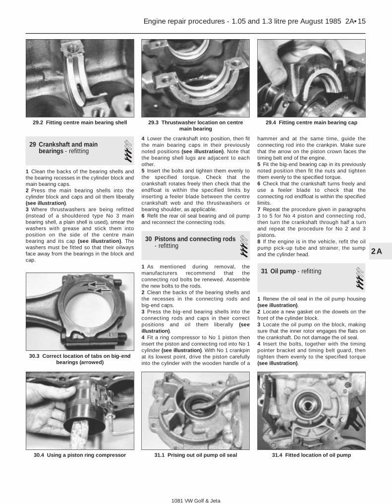
1 Clean the backs of the bearing shells andthe bearing recesses in the cylinder block andmain bearing caps.2 Press the main bearing shells into thecylinder block and caps and oil them liberally(see illustration).3 Where thrustwashers are being refitted(instead of a shouldered type No 3 mainbearing shell, a plain shell is used), smear thewashers with grease and stick them intoposition on the side of the centre mainbearing and its cap (see illustration). Thewashers must be fitted so that their oilwaysface away from the bearings in the block andcap.
4 Lower the crankshaft into position, then fitthe main bearing caps in their previouslynoted positions (see illustration). Note thatthe bearing shell lugs are adjacent to eachother.5 Insert the bolts and tighten them evenly tothe specified torque. Check that thecrankshaft rotates freely then check that theendfloat is within the specified limits byinserting a feeler blade between the centrecrankshaft web and the thrustwashers orbearing shoulder, as applicable.6 Refit the rear oil seal bearing and oil pumpand reconnect the connecting rods.
30 Pistons and connecting rods- refitting 3
1 As mentioned during removal, themanufacturers recommend that theconnecting rod bolts be renewed. Assemblethe new bolts to the rods.2 Clean the backs of the bearing shells andthe recesses in the connecting rods andbig-end caps.3 Press the big-end bearing shells into theconnecting rods and caps in their correctpositions and oil them liberally (seeillustration).4 Fit a ring compressor to No 1 piston theninsert the piston and connecting rod into No 1cylinder (see illustration). With No 1 crankpinat its lowest point, drive the piston carefullyinto the cylinder with the wooden handle of a
hammer and at the same time, guide theconnecting rod into the crankpin. Make surethat the arrow on the piston crown faces thetiming belt end of the engine.5 Fit the big-end bearing cap in its previouslynoted position then fit the nuts and tightenthem evenly to the specified torque.6 Check that the crankshaft turns freely anduse a feeler blade to check that theconnecting rod endfloat is within the specifiedlimits.7 Repeat the procedure given in paragraphs3 to 5 for No 4 piston and connecting rod,then turn the crankshaft through half a turnand repeat the procedure for No 2 and 3pistons.8 If the engine is in the vehicle, refit the oilpump pick-up tube and strainer, the sumpand the cylinder head.
31 Oil pump - refitting 31 Renew the oil seal in the oil pump housing(see illustration).2 Locate a new gasket on the dowels on thefront of the cylinder block. 3 Locate the oil pump on the block, makingsure that the inner rotor engages the flats onthe crankshaft. Do not damage the oil seal.4 Insert the bolts, together with the timingpointer bracket and timing belt guard, thentighten them evenly to the specified torque(see illustration).
Engine repair procedures - 1.05 and 1.3 litre pre August 1985 2A•15
2A
29.2 Fitting centre main bearing shell 29.3 Thrustwasher location on centremain bearing
29.4 Fitting centre main bearing cap
30.3 Correct location of tabs on big-endbearings (arrowed)
30.4 Using a piston ring compressor 31.1 Prising out oil pump oil seal 31.4 Fitted location of oil pump
1081 VW Golf & Jeta

5 Locate a new gasket on the flange facethen fit the pick-up tube and strainer. Insertthe bolts and tighten them to the specifiedtorque.6 Refit the sump, timing belt and sprocket.
32 Sump - refitting 31 If applicable (ie. the engine has beendismantled), refit the crankshaft rear oil sealand housing.2 Clean the mating faces of the sump andcylinder block.3 Locate the new gasket on the block (seeillustration) then fit the sump. Insert the sumpbolts and tighten them evenly in diagonalsequence to the specified torque. If required,the two bolts at the flywheel end of the sump
can be replaced by socket-headed bolts tofacilitate their removal with the engine in thevehicle. Note that the tightening torque for thereplacement bolts is 8 Nm (6 Ibf ft).4 If the engine is in the vehicle, replenish itwith oil, fasten the alternator wire to the sumpclip and lower the vehicle to the ground.
33 Flywheel - refitting 31 Locate the engine plate on the cylinderblock dowels.2 Clean the mating faces of the flywheel andcrankshaft then locate the flywheel in position.Note that the bolt holes only align in oneposition as they are offset.3 Apply locking fluid to the threads of newbolts (see illustration) then insert and tightenthem in a diagonal sequence to the specifiedtorque while holding the flywheel stationary.4 Refit the clutch.
34 Cylinder head - reassembly 31 Fit the valves into their correct locations inthe cylinder head.2 Working on each valve at a time, locate thevalve spring lower seat in position.3 Before fitting each valve seal, locate thespecial plastic sleeve provided in the gasketset over the valve stem in order to preventdamage to the seal (see illustration).4 Slide each new seal over the valve stemand press it firmly onto the guide using ametal tube (see illustration). Remove theplastic sleeve.5 Fit the spring and retainer over each valvestem, then compress the spring with thecompressor and insert the split collets.Release the compressor and remove it.6 Refit the camshaft.
35 Camshaft - refitting 31 Smear a little clean engine oil on the lip andouter edge of the camshaft oil seal then driveit squarely into the cylinder head with a blockof wood.2 Oil the camshaft bearing surfaces then slidethe camshaft into position, taking care not todamage the oil seal.3 Fit the distributor flange, together with anew gasket, and tighten the socket-headbolts.4 Using a feeler blade, check that thecamshaft endfloat is as specified.5 Fit the Woodruff key then fit the sprocket tothe camshaft followed by the spacer and bolt.Tighten the bolt while holding the sprocketstationary with a metal bar and two bolts (seeillustration).6 Fit the cam followers by turning thecamshaft so that the relevant cam lobe peakis pointing away from the valve, then tap thefollower between the valve stem and cam andonto the ball-stud.7 Slide the cam follower clips into thegrooves on the ball studs and locate theupper ends on the cam followers (seeillustration).
2A•16 Engine repair procedures - 1.05 and 1.3 litre pre August 1985
32.3 Fitting sump gasket 33.3 Applying liquid locking fluid toflywheel bolts
34.3 Locate plastic sleeve on valvestem . . .
34.4 . . . then fit the new oil seal 35.5 Method of tightening camshaftsprocket bolt
35.7 Cam follower clip and groove inball-stud
1081 VW Golf & Jeta

8 Adjust the valve clearances.9 Turn the camshaft so that the indentation inthe sprocket is pointing downwards and inline with the pointer on the timing cover plate(see illustration).10 Turn the crankshaft a quarter of a turnclockwise so that the notch in the crankshaftpulley is aligned with the TDC pointer on thefront of the oil pump.11 Fit the timing belt to the camshaftsprocket and coolant pump.12 Using a screwdriver in the coolant pump,
turn the pump anti-clockwise and tension thetiming belt until it can just be turned through90° with the thumb and forefinger midwaybetween the camshaft sprocket and coolantpump.13 Tighten the coolant pump bolts when thebelt tension is correct and check the timingmarks are still aligned.14 Fit the dipstick tube to the cylinder block.15 Fit the timing cover, insert the bolts withthe earth lead and dipstick tube bracket, thentighten the bolts.
16 Press the oil spray tube into the top of thecylinder head.17 Refit the valve cover with a new gasket,locate the reinforcement strips and tighten thenuts and bolts.18 If the engine is in the vehicle, reverse thepreliminary procedures given in Section 10.
36 Cylinder head - refitting 31 Position Nos 1 and 4 pistons at TDC thenturn the crankshaft a quarter of a turnanti-clockwise so that neither of the pistons isat TDC. 2 Ensure that the faces of the cylinder headand block are perfectly clean then locate thenew gasket on the block, making sure that alloil and coolant holes are visible. The gasketpart number should be uppermost (seeillustration).3 Lower the cylinder head onto the gasketthen insert the bolts together with the enginelifting hooks.4 Using a splined key, tighten the bolts in thestages given in Specifications, using thesequence shown (see illustration).5 Refit the coolant pump, if applicable.6 Fit the timing cover plate and insert thecoolant pump bolts loosely.7 If required, refit the camshaft.8 Refit and tighten the timing cover plateupper retaining bolt.9 If applicable, refit the crankshaft sprocketand timing belt to the crankshaft (seeillustration).10 Turn the camshaft so that the indentationin the sprocket is aligned with the pointer onthe timing cover plate.11 Turn the crankshaft a quarter of a turnclockwise so that the notch in the crankshaftpulley (temporarily refit if necessary) is alignedwith the TDC pointer on the front of the oilpump.12 Fit the timing belt to the camshaftsprocket and coolant pump.13 Using a screwdriver in the coolant pump,turn the pump anti-clockwise and tension thetiming belt until it can just be turned through90° with the thumb and forefinger midwaybetween the camshaft sprocket and coolantpump (see illustration).14 Tighten the coolant pump bolts when thetension is correct and check that the timingmarks are still aligned.15 Fit the dipstick tube to the cylinder block.16 Fit the timing cover, insert the bolts withthe earth lead and dipstick tube bracket andtighten the bolts.17 Refit the valve cover with a new gasket,locate the reinforcement strips and tighten thenuts and bolts.18 If the engine is in the vehicle, reverse thepreliminary procedures given in Section 9.
Engine repair procedures - 1.05 and 1.3 litre pre August 1985 2A•17
2A
35.9 Camshaft sprocket (later type) withindex mark aligned with timing cover TDC
pointer
36.2 Correct fitting of cylinder headgasket
36.4 Cylinder head bolt tightening sequence
36.9 Fitting crankshaft sprocket andtiming belt
36.13 Tensioning timing belt
1081 VW Golf & Jeta

37 Timing belt and sprockets -refitting 3
1 Fit the Woodruff key in the crankshaft andtap the sprocket into position .2 Insert the bolt and tighten it to the specifiedtorque while holding the crankshaft stationarywith a lever in the starter ring gear.3 Fit the Woodruff key to the camshaft then fitthe sprocket followed by the spacer and bolt.Tighten the bolt while holding the sprocketstationary with a metal bar and two bolts.4 Locate the timing belt on the crankshaftsprocket then fit the pulley. Insert the boltsand tighten them with an Allen key.5 Turn the camshaft so that the indentation inthe sprocket is aligned with the pointer on thetiming cover plate. Check that the notch in thecrankshaft pulley is aligned with the TDCpointer on the front of the oil pump6 Fit the timing belt to the camshaft sprocketand coolant pump.7 Using a screwdriver in the coolant pump,turn the pump anti-clockwise and tension thetiming belt until it can just be turned through90° with the thumb and forefinger midwaybetween the camshaft sprocket and coolantpump.8 Tighten the coolant pump bolts when thebelt tension is correct and check that thetiming marks are still aligned.9 Fit the timing cover, insert the bolts with theearth lead and dipstick tube bracket, thentighten the bolts.10 If the engine is in the vehicle, reverse thepreliminary procedures given in Section 12.
38 Valve clearances - checkingand adjustment 3
1 The valve clearances can be checked andadjusted with the cylinder head removed(prior to refitting after overhaul) or in thenormal manner described in Section 12 ofChapter 1.2 There are two specified valve clearancesettings, these being for a cold (cylinder headremoved) or warm (engine in vehicle) enginecondition.3 If the valve clearances are adjusted with theengine cold, recheck the clearances againafter 600 miles (900 km) with the engine at itsnormal operating temperature.
39 Engine ancillary componentsand gearbox - refitting 3
Refer to Section 8 and refit the listedancillary components.
Refit the gearbox to the engine, reversingthe procedures described in Section 6.
40 Engine - refitting 4Reverse the removal procedure given in
Section 5 but note the following additionalpoints:a) When lowering the engine/gearbox unit
into the vehicle, ensure that thedriveshafts are aligned with the flanges
b) Assemble the engine mountings looselyinitially and tighten them only after theunit is central without straining themountings (see illustrations)
c) Adjust the clutchd) Adjust the accelerator cable and, where
applicable, the choke cablee) Refill the engine with oil and coolant
41 Engine - adjustments aftermajor overhaul 2
1 With the engine/gearbox unit fitted to thevehicle, make a final check to ensure thateverything has been reconnected and that norags or tools have been left in the enginecompartment.2 If new pistons or crankshaft bearings havebeen fitted, turn the carburettor engine speedscrew in about half a turn to compensate forthe initial tightness of the new components.3 Fully pull out the choke (manual chokemodels) and start the engine. This may take alittle longer than usual as the fuel pump andcarburettor float chamber may be empty.4 As soon as the engine starts, push in thechoke to the detent. Check that the oilpressure light goes out.5 Check the oil filter, fuel hoses and coolanthoses for leaks.6 Run the engine to normal operatingtemperature, then adjust the slow running(idle).7 If new pistons or crankshaft bearings havebeen fitted, the engine must be run-in for thefirst 500 miles (750 km). Do not operate theengine at full throttle or allow the engine tolabour in any gear.8 Although not strictly essential, it is goodpractice to change the engine oil and filterafter the initial running-in period. This will getrid of the small metallic particles which areproduced by new components bedding in toeach other.
2A•18 Engine repair procedures - 1.05 and 1.3 litre pre August 1985
1081 VW Golf & Jeta
40.1a Engine mounting bolt identification - see Specifications for torque settings
40.1b Engine/transmission mounting bolt identification -see Specifications for torque settings