?0i^ agriculture unhed states ^ department of iffects of
TRANSCRIPT

UnHed States ^ Department of Agriculture
Agricultural Research Service
Agriculture Handbook Number 696
?0i^ iffects of Electrical
Voltage/Current on Farm Animals
How To Detect and Remedy Problems
a: O;
- ;
Lefcourt, A.M., ed. 1991. Effects of Electrical Voltage/Current on Farm Animals: How To Detect and Remedy Problems. U.S. Department of Agriculture, Agriculture Hand- book No. 696, 142 pp.
This handbook examines 1) the history of stray voltage/current problems on farms, 2) the physical and electrical sources of stray voltage/current phenomena, 3) the physiological and behavioral bases for losses in milk production, 4) methods for iden- tifying and detecting stray voltage/current problems, 5) methods for mitigating such problems, and 6) areas where further research may be warranted. While the primary emphasis is on cattle and dairy farms, the theories and procedures discussed are com- pletely relevant to all tj^es of livestock and livestock housing facilities. Recommenda- tions are made for action levels and concerning mitigation techniques. The fundamental conclusion of this handbook is that stray voltages/currents can be reduced to acceptable levels.
KEYWORDS: Stray voltage/current, neutral-to-earth voltage, electrical shock, history, sources, physiological effects, behavioral modifications, mitigation, dairy farms, cows.
Trade names are used in this publication solely to provide specific information. Men- tion of a trade name does not constitute a guarantee or warranty of the product by the U.S. Department of Agriculture or an endorsement by the Department over products not mentioned.
Copies of this publication can be purcliased from the Superintendent of Documents, Govern- ment Printing Office, Washington, DC 20402.
Microfiche copies can be purchased from the National Technical Information Service, 5285 Port Royal Road, Springfield, VA 22161.
Agricultural Research Service has no additional copies for free distribution.
Issued December 1991
ISBN 0-16-036208-3
9 780160"362088
90000 For sale by the U.S. Government Printing Office Superintendent of Documents, Mail Stop: SSOP, Washington, DC 20402-9328
ISBN 0-16-036208-3

This handbook is dedicated to the memory of Robert Appleman. Dr. Appleman was a pioneer in the field of stray voltage, and he continued his efforts to find and disseminate harmonious solutions to this problem until his untimely death on June 21,1991.

Preface
There were two primary reasons for publishing this handbook. First, we, as scientists, were distressed that our research results were being misinterpreted and misconstrued in media and in courtrooms. Second, we were disheartened by the animosity that some- times arose among livestock farmers, dairy equipment manufacturers, and public utilities companies because of a lack of understanding of the causes and effects of stray voltages on farms. For these reasons, we met at Cornell University in May of 1988 to review our opinions and concerns, and to discuss the possibility of publishing a "white paper" on stray voltage. At this meeting, we concluded that there was an ex- cellent possibility that a consensus could be reached, and a second meeting was scheduled for October in Minneapolis.
At the first meeting, the question of funding for future meetings and, if relevant, publi- cation of the "white paper" was raised. Several foxmdations and agencies funded prin- cipally by utilities or dairy cooperatives had offered financial support. However, to eliminate any and all potential for even the appearance of bias, we decided to accept no industry funding whatsoever. All travel and meeting expenses were borne by in- dividuals, generally by utilizing university or Government funds.
At the second meeting, a firm consensus was reached that a "white paper" should be published and that it be published as a U.S. Department of Agriculture (USDA) Hand- book. The Department was chosen as publisher because it represents an imbiased source of fiznds to pay for publication, because it has a mechanism for making avail- able publications to the public through the Government Printing Office, and because federal publications are 1) imderstood by the general population to be unbiased and 2) normally viewed as expert testimony in legal proceedings.
To guarantee that the oral consensus reached at the second meeting was faithfully transferred to paper, we decided on a rather complex procedure for actually writing the manuscript. Chapters were written under the guidance of chapter editors, who then distributed copies of the chapters to all participants for comment. Next, these chapter editors revised their chapters and sent copies to the editor in chief, who as- sembled and integrated the chapters into a manuscript. The manuscript was dis- tributed to all participants to ensure that all comments had been dealt with satisfactorily by the chapter editors. In addition, as part of the original agreement among contributors, Lloyd B. Craine served as the in-depth reviewer. Remaining problems were addressed to the editor in chief for reconciliation. Subsequently, the USDA's Agricultural Research Service Information Staff and Office of Public Affairs reviewed the manuscript. Ultimately, the edited manuscript was distributed for final approval, and each contributor signed a notice acknowledging that the manuscript was factually correct and a faithful represention.
Alan M. Lefcourt Editor in chief

Contributors
Daniel J. Aneshansley, Ph.D. Associate Professor Cornell University Dept. of Agricultural & Biol. Engineering Ithaca, NY 14853
Robert Appleman, Ph.D. Professor & Extension Animal Scientist Dairy Management University of Minnesota Department of Animal Science St. Paul, MN 55108
Harold Cloud, Ph.D. Professor (retired) University of Minnesota Department of Agricultural Engineering St. Paul, MN 55108
Lloyd B. Craine Professor (Emeritus) Washington State University Electrical and Computer Engin. Depart. Pullman, WA 99164-2752
H. David Currence, Ph.D. Associate Professor University of Missouri Agricultural Engineering Department Columbia, MO 65201
R. C. Gorewit, Ph.D. Professor Cornell University Department of Animal Science Ithaca, NY 14853
Paul Gumprich New Liskeard College of Agr. Tech. RO. Box "G" New Liskeard, Ontario Canada POJ IPO
Robert Gustafson, Ph.D. Professor & Head The Ohio State University Agricultural Engineering Department 590 Woody Hayes Dr. Columbus, OH 43210
Ben Hawkin Head of Engin. & Anim. Sei. New Liskeard College of Agr. Tech. P.O. Box "G" New Liskeard, Ontario Canada POJ IPO
David Kammel, Ph.D. Assistant Professor Extension Agricultural Engineer University of Wisconsin-Madison Agricultural Engineering Department Madison, WI 53706
Alan M. Lefcourt, Ph.D. Biomédical Engineer U.S. Department of Agriculture Agricultural Research Service Milk Secretion and Mastitis Laboratory Beltsville, MD 20705
David C. Ludington, Ph.D. Professor Cornell University Dept. of Agricultural & Biol. Engineering Ithaca, NY 14853
Roger Pellerin, M.E. Research Associate Cornell University Dept. of Agricultural & Biol. Engineering Ithaca, NY 14853
Lee Southwick Extension Associate NY State College of Vet. Medicine Cornell University Quality Milk Promotion Service Ithaca, NY 14850
Láveme Stetson, P.E. U.S. Department of Agriculture Agricultural Research Service University of Nebraska - East Campus Lincoln, Nebraska 68583

Warning
Identification and, particularly, diagnosis of stray voltage problems can require considerable electrical expertise. That is not to say that the input of farmers is not necessary and valuable. Often, the input and observations of people in daily association with a stray voltage/current prob- lem are critically important to its solution. However, electrical systems can be dangerous. Persons without special training should never attempt investigation of the electrical distribution or farm electrical systems. For example, persons without special training should never open electrical ser- vice panels nor should they even contemplate altering any wiring.
Using a voltage measuring device with well insulated probes to measure voltages between pos- sible points of animal or human contact should not result in a safety hazard with one important exception. Voltages that cause stray voltage/current problems are normally so low that they can- not be detected without special instruments. If an electrical shock can actually be felt or if animals are knocked down, a possible hazard to life exists. The device or electric circuit respon- sible for the shock should be disconnected by unplugging the device or by deenergizing the cir- cuit at the service panel. The situation should be examined by an electrical professional as soon as possible.

Contents
1. Introduction 1 Robert D. Appleman, editor
Summary 1-1
History 1-2
Recognition 1-2
Early Field Experiences 1-2
Solutions 1-3
Where Do We Stand Now? 1-4
2. Sources of Stray Voltage/Current 2 David Ludington, editor
Summary 2-1
Sources 2-4
Characteristics of a Source 2-4
Neutral/Ground System Voltage to Earth 2-5
Voltage Drop in Secondary Neutral 2-7
Neutral/Ground Bus and Equipment Grounds 2-10
Excessive Secondary Neutral Current 2-13
Caveat 2-17
Power Delivery Systems 2-17
Power Generation and Transmission 2-18
Primary Distribution 2-18
Single-Phase Service Drops 2-19
Three-Phase Service Drops 2-22
Additional Sources of Information 2-22
3. Physiological and Behavioral Effects 3 Daniel J. Aneshansley and R. C. Gorewit, editors
Sunmiary 3-1
Introduction 3-3
Physiological Basis for Sensitivity to Currents 3-3
Human Sensitivity 3-3
Electrical Currents That Affect Dairy Cows 3-4
Voltage Sensitivity 3-5

Controlled Research 3-5
Behavior and Physiology 3-5
Production, Reproduction, and Health 3-11
Observations From Dairy Farms 3-14
Sjonptoms Attributed to Stray Voltage 3-14
Farm Surveys 3-15
Problems with Interpreting Survey Data 3-18
Factors Affecting Response 3-18
Perception and Interpretation of Stimuli 3-19
Predictability and Controllability of Stimuli 3-19
Genetic Selection 3-20
Lactation 3-20
Learned Behavior 3-20
Animal-Operator Interaction 3-21
Conclusion 3-22
4. Mitigation 4 Robert Gustafson^ editor
Summary 4-1
Voltage Reduction 4-2
Active Voltage Suppression 4-3
Gradient Control 4-4
Retrofitting Existing Facilities 4-10
Isolation 4-12
Whole Farm Isolation 4-12
Single-Building-Service Isolation 4-16
Isolation of Grounded Equipment Within a Single Service 4-18
Conclusion 4-20
Appendix: Examples 4-21
Example 1. Single-Phase Distribution Line 4-21
Example 2. Single-Phase Farmstead 4-22
5. Detection and Measurement 5 LaVeme Stetson, editor
Summary 5-1
Detection 5-2
Point to Point 5-2
Point to Reference Ground 5-3
Interpreting Measurements 5-4
Instruments 5-6
Measurements 5-6
Voltage 5-6
Current 5-9
Resistance 5-10
Equipment Grounding 5-11
Investigation Procedures 5-13
Farm Secondary Systems 5-14
Primary Distribution Systems 5-14
Additional Sources of Information 5-15
6. Recommendations for Research 6 Lloyd B. Craine, editor
Summary 6-1
Introduction 6-2
Physiological EfiTects 6-2
Power Systems 6-2
Load Growth 6-3
Power Quahty 6-3
Transients 6-3
Power System Maintenance 6-4
General Recommendations on Power Systems 6-4
Direct Current Voltages and Direct Currents 6-5
Measurement Problems 6-5
Electric and Magnetic Fields 6-6
Sensitivity of Animals 6-6
Where To Obtain Additional Information 6-7
Mitigation Equipment 6-7
7. Annotated Summary and Recommendations 7 Alan M. Lefcourt, editor
Summary 7-1
Definition of Stray Voltage 7-3
An Elevated Neutral-to-Earth Voltage Is Not
Stray Voltage Per Se 7-3
History 7-4
Sources 7-4
Animal Contact 7-5
Cicuit Impedances 7-5
Neutral-to-Earth Voltages 7-7
Leakage or Coupled Sources 7-7
Physiological and Behavioral Effects 7-7
Sensitivity to Electric Currents 7-8
Electrical Currents That Affect Dairy Cows 7-8
Impedance of Cows 7-8
Normal Cow Behavior 7-8
Behavioral Responses to Current 7-8
Physiological Responses to Current 7-9
Factors Influencing Responses to Stray Voltages 7-10
Mastitis 7-10
Caveat 7-10
Conclusions. 7-10
Mitigation 7-11
Voltage Reduction 7-11
Active Voltage Suppression 7-11
Gradient Control 7-11
Isolation 7-12
Detection and Measurement 7-13
Warning 7-13
Basic Measurement Procedures 7-14
Instrumentation 7-15
Investigation Procedures 7-15
Identification of Sources 7-16

Future Research 7-16
Physiology 7-16
Power Systems 7-16
Recommendations 7-17
Action Levels 7-17
New Construction 7-18
Existing Problems 7-18
8. Bibliography 8 David Kammel, editor
9. Glossary 9 David Currence, editor

Figures
Figure 2-1. Diagram of a path through two animal contact points. 2-5
Figure 2-2. Schematic of a model for an electrical path from neutral bus to earth through two animal contact points. 2-6
Figure 2-3. Schematics of neutral/ground system between an outbuilding and transformer and of equivalent circuits. 2-9
Figure 2-4. Schematic of neutral/ground bus with attached conductors and bonds. 2-11
Figure 2-5. A branch circuit with power conductors (B&W) and equipment ground (G) properly connected. 2-11
Figure 2-6. A branch circuit with power conductors (B&W) and equipment ground (G) properly connectd. A connection (RG) between the equipment and earth ex- ists. 2-12
Figure 2-7. Fault in properly wired equipment causes fault current to flow toward trans- former. 2-12
Figure 2-8. Three-conductor 120/240-V secondary distributions with balanced (A) and un- balanced (B) loads. Each load is 600 W. 2-13
Figure 2-9. Improper use of the white conductor (neutral) as an equipment grounding con- ductor. Frame should not be bonded to neutral. 2-15
Figure 2-10. Improper interconnection of white conductor (neutral) and the equipment grounding conductor (G). These conductors must be separated. 2-15
Figure 2-11. Leakage current to earth from an energized buried electric cable. 2-15
Figure 2-12. Improper grounding of remote equipment with ground rod. 2-16
Figure 2-13. Multigrounded neutral distribution system (wye). 2-19
Figure 2-14. Delta distribution system. 2-20
Figure 2-15. Open delta distribution system. 2-20
Figure 3-1. An equivalent electrical circuit showing the elements that must be in place for a stray voltage problem to exist. V is the voltage source and Z's are circuit impedances. Current equals V divided by series impedance. 3-5
Figure 3-2. Time elapsed before a cow drank 1 gallon of water as a function of the volt- age applied between the waterer and the rear hooves of the cow. The ex- tremes at each voltage represent the range of responses for all animals. The solid areas represent the standard errors of the means. 3-12
Figure 3-3. Changes in rolling herd average of cows before and after isolation. Herds are separated into two groups; those that showed an abrupt increase in rolling herd average after isolation and those that showed little change. Dairy Herd Improvement (DHI) trend for other herds in the region of the survey is also shown. 3-16
Figure 3-4. Behavioral and milk production responses to increasing current levels. Voltages (right vertical axis) were estimated using a worst-case circuit impedance (500 ohms) and a more realistic impedance (1,000 ohms). 3-22
Figure 4-1. A four-wire feeder from farm main to outbuilding. Note that the neutral in the outbuilding is not bonded to the grounding bus (GR) but is bonded at the main service. 4-2
Figure 4-2. Voltage suppression by controlled current to earth. 4-3
Figure 4-4. Animal approaching an equipotential plane. 4-4
Figure 4-3. Animals on equipotential planes. All body contacts are at the same potential. 4-5
Figure 4-5. Milkline bond. 4-6
Figure 4-6. Equipotential plane in stall barn: top, typical layout of reinforcing rod grid and overlying mesh in a stall dairy barn; bottom, three-dimensional view. 4-8
Figure 4-7. Equipotential plane in a milking parlor: top, cross-sectional view; bottom, three- dimensional view. Note that the operator pit is part of the plane. 4-9
Figure 4-8. Voltage ramp adjacent to an equipotential plane: top, side view; bottom, frontal view. 4-10
Figure 4-10. Retrofit equipotential plane in milking parlor. 4-11
Figure 4-9. Retrofit equipotential plane in stanchion/tie stall barn. 4-11
Figure 4-11. Secondary-neutral voltage-drop distribution under case-1 and case-2 conditions. 4-13
Figure 4-12. Apparent impedance characteristics of three saturable reactors.. 4-15
Figure 4-13. Isolation device test circuit. Values for Ep and Ep are shown in figure 4-14. (Subscripts P and F stand for primary and farmstead, respectively.) 4-16
Figure 4-14. Part-cycle saturation and triggering waveforms. 4-17
Figure 4-15. Peak and rms voltages vs. source voltage for three saturable reactors. 4-18
Figure 4-18. Saturating reactor application at a building service entrance. 4-18
Figure 4-17. Isolation transformer installation, single service. 4-19

Figure 4-16. Isolating transformer installation, whole farmstead. 4-19
Figure 4-A1. Ten-farm, single-phase-line model. 4-21
Figure 4-A3. Ten-farm model, fault-to-earth examples. 4-24
Figure 4-A2. Ten-farm model, nonfault examples. 4-24
Figure 4-A4. Ten-farm model, bad-connector examples. 4-25
Figure 4-A5. Ten-farm model, voltage suppression at a selected location. 4-25
Figure 4-A6. Ten-farm model, modified system resistance. 4-26
Figure 4-A7. Example farmstead system. 4-26
Figure 5-1. Point-to-point method of voltage measurement in cow contact area. 5-2
Figure 5-2. Point-to-reference-ground method of voltage measurement. 5-3
Figure 5-3. General animal-path measurement circuit. 5-4
Figure 5-4. Voltage measurement using a high-impedance meter and a leakage path. 5-4
Figure 5-5. Current measurement with an ammeter and a low-impedance-source path. 5-5
Figure 5-6. Voltage measurement with shunt and a high-impedance reference ground show- ing voltage divider effect. 5-8
Figure 5-7. Checking a meter for the ability to separate ac and dc voltages. 5-8
Figure 5-8. Use of blocking capacitor when meter does not separate ac and dc voltages. 5-8
Figure 5-9. Voltage measurement using a shunt resistor to test the current-producing capacity of a source voltage. 5-8
Figure 5-10. An analog volt-ohm-milliammeter. The meter indicates 1.6 V on the 2.5-Vac scale. 5-8
Figure 5-11. A current reading with a 500-ohm resistor in series to approximate the mini- mum contact and body resistance of an animal. 5-10
Figure 5-12. Test setup for measuring grounding electrode resistance by the fall-of-potential method. V = voltmeter, A = ammeter, Ci » electrode to be tested, C2 » cur- rent injection electrode, and P2 = voltage measurement electrode. 5-11
Figure 5-13. An insulation or ground fault test on deenergized systems. 5-12

Figure 7-1. An equivalent electrical circuit showing the elements that must be in place for a stray voltage problem to exist. V is the voltage source and Z's are circuit impedances. Current equals V divided by series impedance. 7-5
Figure 7-2. Behavioral and milk production responses to increasing current levels. Vol- tages, on the right, were estimated using a worst case circuit impedance and a more realistic impedance. 7-9
Figure 7-3. Voltage measurement using a high-impedance meter and a leakage path. 7-14
Figure 7-4. Voltage measurement using a shunt resistor to test the current-producing capacity of a source voltage. 7-14
Tables
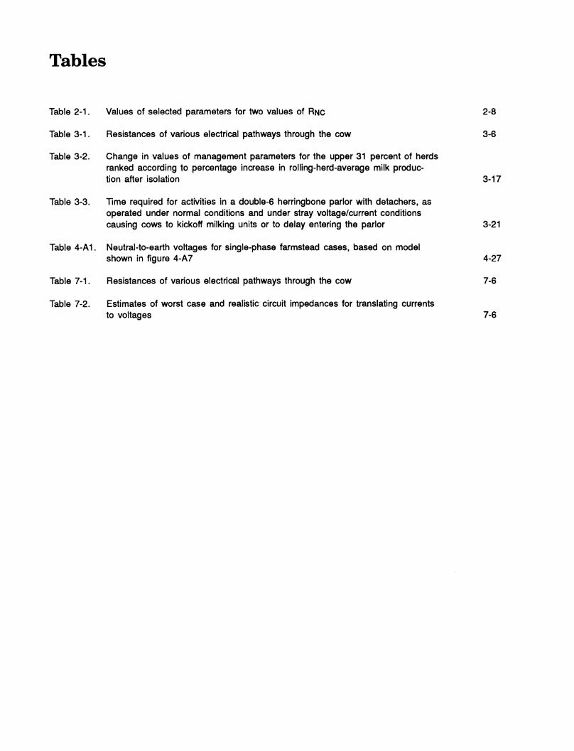
Table 2-1. Values of selected parameters for two values of RNC
Table 3-1. Resistances of various electrical pathways through the cow
Table 3-2. Change In values of management parameters for the upper 31 percent of herds ranked according to percentage increase in rolling-herd-average milk produc- tion after isolation
Table 3-3. Time required for activities in a double-6 herringbone parlor with detachers, as operated under normal conditions and under stray voltage/current conditions causing cows to kickoff milking units or to delay entering the parlor
Table 4-A1. Neutral-to-earth voltages for single-phase farmstead cases, based on model shown in figure 4-A7
Table 7-1. Resistances of various electrical pathways through the cow
Table 7-2. Estimates of worst case and realistic circuit impedances for translating currents to voltages
2-8
3-6
3-17
3-21
4-27
7-6
7-6
Effects of Electrical Voltage/Current on Farm Animals: How To Detect and Remedy Problems
1. Introduction Robert D. Appleman, editor
Summary sources, gradient control by use of equipotential planes, and isolation.
While stray voltages / currents cannot be totally eliminated, they can be reduced.
While some knowledge of stray voltage has ex- isted for many years, it was not until about 1982 that the national and worldwide nature of this phenomenon was recognized. Even when livestock problems were recognized, early solutions were not always fully effective and/or were not always satisfactory to both farmers and power suppliers. One of the challenges to solving stray voltage/cur- rent problems has been in persuading everyone in- volved to work as a team in diagnosing and solving the problems on the basis of a rational un- derstanding of the factors involved.
Numerous research studies have quantified the physiological and behavioral responses of dairy cat- tle to electric currents. Cows were found to be more susceptible to stray voltages compared to humans due to cows' relatively lower body resistan- ces. Animals respond to current and not directly to the voltage that produced the current. Ohm's law states that current equals voltage divided by resistance. Thus, for a given voltage, a lower body resistance will result in a higher current (and a greater effect). Even so, it is important to realize that the currents required for perception, be- havioral change, or physiological effects to occur are widely variable. Furthermore, symptoms as- sociated with stray voltage/current problems are not unique and many factors other than stray volt- age/current can cause similar behavior, health, and/or production problems.
The sources of relatively small amounts of electri- cal currents passing through animals are often very difficult to locate. Stray voltages/currents may arise because of poor electrical connections, corrosion of switches, frayed insulation, faulty equipment, or heavily loaded power lines.
Solutions to stray voltage/current problems in- clude voltage reduction, control of leakage voltage
Introduction 1-1

History
Recognition
Anyone who has been involved in identifying, diag- nosing, and correcting stray voltage/current problems in livestock facilities recognizes their complexity. These problems often cause frustra- tion, since many, if not most, livestock farmers have little imderstanding of electrical distribution and farmstead wiring systems. At the same time, few electrical workers understand the behavioral and physiological responses of animals to small electrical currents. Furthermore, the importance of the farmers' reactions to these problems is not generally appreciated; i.e., their reaction to live- stock behavioral changes associated with stray vol- tages/currents may create even more serious problems.
One of the challenges of solving stray voltage/cur- rent problems has been in persuading everyone in- volved to work as a team in diagnosing and solving the problems on the basis of a rational im- derstanding of the factors involved. Successful solu- tion of stray voltage/current problems usually involves many people, including the livestock (usually dairy) farmer, electrician, power supplier, milking equipment representative, veterinarian, milking company fieldman, nutrition consultant, and county Extension agent. It is very easy, par- ticularly under the stress of serious economic los- ses, to try to shift the responsibility for the diagnosis and solution of a suspected problem to one person or organization. In most cases, team- work by, rather than animosity among, the people involved is necessary to quickly diagnose and cor- rect an existing problem.
It has been known for many years that problems associated with the management and milking of dairy cows may occur when relatively small electri- cal currents pass through cows' bodies. An Australian researcher (Churchwood 1948) implied that current resulting from electrical equipment in the milking area may have affected cows negative- ly. Similar statements were published some years
later in New Zealand (Phillips 1962a and b). The first cases of stray voltage on the North American continent were reported in Washington State in 1969 (Graine et al. 1969a and 1970) and in Canada in 1975 (Feistman and White 1975). These cases were assumed to be unusual and to represent a primarily localized problem; thus, they received little attention and publicity in the popular press and trade journals.
Beginning in 1977, numerous farms with stray voltage/current problems were identified in the upper Midwest and east coast regions of the United States and Canada. Between 1978 and 1982, several comprehensive Extension Service bul- letins relating to the identification and solution of stray voltage/current problems were prepared, the one by Cloud et al. (1980) being the most widely distributed throughout the United States.
By 1982, numerous articles and news releases con- cerning stray voltage were published. For ex- ample. Hoard's Dairyman — a popular magazine that most dairy farmers receive — published at least 12 articles, notes, or references related to the subject between 1980 and 1983. This period marked the beginning of national and worldwide recognition of stray voltage. The proceedings of a workshop on stray voltage in Minneapolis, Min- nesota, were published in 1983 (National Rural Electric Cooperative Association 1983). In 1984, a national stray voltage symposium was held in Syracuse, New York; the proceedings of the sym- posium were published in 1985 by the American Society of Agricultural Engineers (Majerus et al. 1985). In the same year, a comprehensive review appeared in the Journal of Dairy Science (Ap- pleman and Gustafson, 1985b).
Early Field Experiences
The first farms in which stray voltage/current problems were identified were suffering severe los- ses of milk production and income. The producers were generally aware they had problems and had spent considerable time and money attempting to improve their feeding program, the milking equip- ment, their milking procedures, and hygiene. But nothing seemed to help. Finally, when stray vol- tages/currents were measured and appropriate cor-
1-2 Robert D. Appleman

rective procedures were completed, favorable responses were often immediate and dramatic. In- creases in daily milk production of 10 to 15 poimds per cow (20 to 30 percent) were com- monplace. Improved cow temperament and a sig- nificant reduction in the time required to complete milking chores were often cited by farmers. Im- proved udder health, less mastitis, and improved milk quality were also frequently reported respon- ses.
When these results were passed on to neighbors, and when reports began to appear in the popular press, other farmers suspected that they, too, might have similar problems and were quick to make demands of their electrical power suppliers, farm electricians, and milking equipment dealers. In general, these people had little knowledge of how and what levels of electrical current can ef- fect animals, were xmaware of methods for sys- tematically identifying and mitigating stray voltage/current problems, and often reacted to the farmers with disdain and contempt. Sometimes, no real problem existed; other times, attempts were made to shift the responsibility of diagnosis and solution to other persons or organizations. When the latter occurred, farmers felt that no one cared, animosity between two or more individuals developed, and the teamwork required to solve the problem quickly dissolved.
In the 1980's, as a direct result of continuing re- search efforts, appropriate diagnostic and mitiga- tion procedures were developed and adopted. Many dairy groups, including university Extension Services, conducted training sessions for persons with electrical expertise, held information sessions for producers and others providing support and as- sistance to dairy farmers, and established more imiform procedures for diagnosis and mitigation. It is hoped that the sense of teamwork needed for cooperation has been established.
Solutions
The causes of relatively small amounts of electri- cal current passing through cows are often very difficult to identify. Some factors that contribute to excessive voltages are poor connections, cor- rosion of switches, frayed insulation, faulty equip-
ment, and heavily loaded power lines. Problems are frequently time dependent; e.g., problems during evening milkings are common. Someone who is familiar with electrical systems, wiring, and equipment and who is knowledgeable about stray voltage/current should be consulted and, if possible, be present when measurements are being made.
Solutions to the problem have included 1) voltage reduction by removal of bad neutral connections and faulty loads or by neutral current reduction by load balancing; 2) control of leakage voltage sources, i.e., removing or correcting wiring, ground- ing, and electrical loads; 3) gradient control by use of equipotential planes; and 4) isolation (See "Glossary" for definition of terms).
One significant problem was and continues to be that many farms are not wired and maintained in accordance with the National Electrical Code (the code which covers farm electrical wiring systems). Bringing farms to present code standards oflen, but not always, solves stray voltage/current problems. In the past, rewiring or improvement of electrical systems was one of the first solutions suggested to farmers. If rewiring failed to solve the problem, as it often did, farmers were then asked to install an equipotential plane in their milking area. Farmers were often reluctant to do so because of the difficulty and expense involved in replacing concrete already in place and perfect- ly usable. An alternative solution was isolation. If the problem source was primarily off-farm, and if tests showed that leaving the farm neutral discon- nected from the primary neutral at the farm trans- former eliminated the problem voltages, farmers wanted to operate in that manner. (This solution was sometimes termed "the disconnect.") Unfor- tunately, neutral disconnection is a cause of sig- nificant safety concern and is a violation of the National Electrical Safety Code (the code under which the power suppliers operate). Because of safety considerations, the primary and farm neutrals must remain connected imder fault condi- tions and during lightning strikes. The problem was to allow the neutrals to be disconnected under normal operating conditions without affect- ing safety. The power supply industry turned to the installation of isolation transformers.
Introduction 1-3

Installation of isolation transformers results in some system grounding being removed from the distribution system. Some electrical experts be- came apprehensive about this reduced grounding; and since isolation transformers are relatively ex- pensive, some farmers resisted having to pay for them and, as required in some instances, also their installation costs. The farmers felt that the costs should not be their responsibility, because the transformers eliminated what the farmers per- ceived to be solely an off-farm problem. But most farmers made the purchase and, seeing favorable results, were simply happy to have the problem solved and appreciated the efforts of everyone in- volved in the diagnosis and mitigation process. Other devices to allow effective isolation while providing interconnections during faults have been developed. For example, devices to balance neutral- to-ground voltages at a point on the distribution system are available.
Where Do We Stand Now?
Today, stray voltage/current is a recognized phenomenon. The theoretical basis for stray volt- age/current problems is understood, sources can be identified, and cost-effective solutions exist.
Numerous research studies have quantified the physiological and behavioral responses of dairy cat- tle to electric currents. Cows were found to be more susceptible to stray voltages compared to humans due to cows' relatively lower body resis- tances. Animals respond to current and not direct- ly to the voltage that produced the current. Ohm's law states that current equals voltage divided by resistance. Thus, for a given voltage, a lower body resistance will result in a higher current (and a greater effect). Even so, it is important to realize that the currents required for perception, be- havioral change, or physiological effects to occur are widely variable. Furthermore, symptoms as- sociated with stray voltage/current problems are not unique and many factors other than stray volt- age/current can cause similar behavior, health, and/or production problems.
The primary impact of stray voltages/currents on milk production involves changes in behavior. Be- cause the effects of stray voltages/currents are primarily behavioral rather than physiological, good milk yield can probably be maintained despite the presence of moderate levels of stray voltage/current if the farming practice is good. One important conclusion concerning behavioral responses to electrical stimulation is that a farmer's reaction to animal behavioral changes can magnify existing management problems or even create new and more serious problems.
Detection of a stray voltage/current problem depends on the type of the problem, the knowledge of the investigator, and the use of standard electrical equipment for making measure- ments. It is important that the equipment and pro- cedures used in the detection and measurement of stray voltage/current be matched to the desired function and to the electrical expertise of the in- vestigator. While standard electrical instruments are adequate for most types of measurements re- quired for stray voltage investigations, these meas- urements should be interpreted by professionals skilled in detecting the sources of stray volt- age/current problems and making mitigation recommendations.
Approaches for controlling neutral-to-earth vol- tages fall into four categories: 1) voltage reduc- tion, 2) active suppression, 3) gradient control, and 4) isolation. Most on-farm sources can be dealt with by improvement of wiring and elimina- tion of faults (voltage reduction). The most com- mon off-farm source is the inherent impedance of the grounded neutral system of the primary. All the approaches listed above are conceptually soimd; all have their advantages and disad- vantages. The most suitable approach in any given situation must be based on the available in- formation and constraints of the situation.
Problems that may arise due to the use of electri- cal power on farms and the principles that apply to the mitigation of particular problems that may affect dairy cattle productivity and health are well imderstood. However, there is need for further re- search; and the types of research needed are iden- tified and discussed in chapter 6.
1-4 Robert D. Appleman

While stray voltage cannot be totally eliminated, it can certainly be reduced to an acceptable level. The procedures and processes for reduction are dis- cussed in the chapters that follow.
Introduction 1-5

2. Sources of Stray Voltage/Current David Ludington, editor
Summary
Stray voltage is a small voltage (less than lOV) that can be measured between two possible con- tact points. If these two points are contacted by an animal or person, a current will flow. The amoimt of current depends on the voltage and the circuit impedance, which includes the source, con- tact, and body impedances. Animals or persons respond to the resulting current flow and not to the applied voltage. Thus, it is important to deter- mine the current level so that the expected response can be predicted according to data generated by controlled scientific tests. The curent can be reliably estimated by measuring (at the time of contact) the voltage across the contact points and dividing by the sum of the contact and body impedances, in accordance with Ohm's law. Relationships among current levels and t)T[)es of responses are discussed in chapter 3, "Physiologi- cal and Behavioral Effects."
An observed voltage may come from a low-internal- impedance source (such as from current flow through a neutral/groxmding system to earth) or a high impedance source (such as from leakage resis- tance across insulation, or field coupling). It is im- portant to remember that the internal source and the load impedances combine to limit the current that will flow; e.g., a high impedance source will limit current flow regardless of the magnitude of the load impedance.
Low Impedance Sources A low impedance source is identified as a source whose measured voltage decreases only slightly when a low impedance load is connected in paral- lel across it. The neutral/grounding system of the distribution line primary and/or the farm secon- dary system is the usual low-impedance source for stray voltage. Load, leakage, and/or fault currents flowing through the impedances of the neutral, grounding conductors, and earth produce voltages across these impedances. The multiple connections of the neutral/grounding system to earth throxigh groimd rods, metallic water lines, or other ground electrodes mean that there will always be voltages
to earth. Any metallic structure connected to the neutral or to the grounding system will be at some small voltage to earth. The following are some examples of conditions that produce or in- crease this neutral/ground system voltage to earth.
♦ Primary neutral-to-reference-ground voltage: The magnitude of a neutral-to-reference- ground voltage is a function of the currents flowing in the neutral/grounding system and the points between which the voltage is measured. For power-distribution systems with a primary neutral, the primary neutral is part of this neutral/grounding system, and current from the primary neutral can result in the measurement of an excessive voltage be- tween the point of interconnection of the primary and secondary neutrals at the dis- tribution transformer, and a reference ground.
♦ Unbalanced loads: In a 120/240-volt three-con- ductor system, the ideal is to keep the 120- volt loads continually balanced between the two hot conductors and the neutral so that no current flows in the neutral. However, the cur- rent draw by certain loads, e.g., motors and lights, varies according to such factors as time of day, season, and relative position of the loads along the distribution system. Therefore, it is impossible to completely balance loads. Substantially imbalanced loads will produce high currents (and thus voltages to earth) in the secondary neutral system. The high start- ing currents associated with motors means that there will often be momentary high cur- rents (and voltages), called transients, on the system.
♦ Faults: Fault currents result from a low resis- tance contact between conductors having con- siderable voltage on them and a metallic (equipment frame) or conducting material (water, earth). The fault may be from the full voltage of the line (if directly from a line con- ductor) or from some lower voltage, such as a water heater element or a winding on a motor. The fault current may be large enough to cause a circuit breaker or fuse to open, thus preventing any serious effects of the
Sources 2-1

fault or the fault current. The circuit breaker may not operate if an alternate path to ground limits current flow in the neutral or if a high impedance in the circuit limits current flow. Fault currents can produce relatively high stray voltages, which need to be cor- rected.
♦ Bad connections: Bad, corroded (high resis- tance), loose, or broken (open) connections can increase the impedance of an otherwise low impedance circuit. Current flow through the high resistance will increase the chances that the current will take an unintended path, and produce stray voltage/current problems.
♦ Improper wiring: The interconnection of the neutral (white) conductor and the equipment grounding (green or bare) conductor at each building service entrance (with one exception, see "Voltage Reduction" in chapter4) is re- quired by electrical codes. Compliance with the codes means that the neutral and ground- ing conductors will be at the same voltage at points of interconnection. All electrical equip- ment, with the exception of some portable equipment, is required to be grounded. Cur- rents in the grounding conductor will also cause voltages to earth to appear. Improper grounding practices may be of the following tjrpes: 1) use of neutral (white wire) also as the groimding conductor and 2) use of a ground rod at the unit instead of a conductor leading back to the service entrance.
High Impedance Sources A high impedance source is a source whose measured open-circuit voltage decreases greatly when a load is appropriately applied between the two contact points. Two types of high impedance sources may occur on farms.
♦ Leakage Paths: Leakage paths can result from the presence of moisture and dirt on insulat- ing surfaces, as well as from the presence of damaged, cracked, or broken insulation on con- ductors, on terminal boards, or in equipment. A leakage path results when one of these con- ditions provides a path for current to leak to metallic parts or to other conductors. A resis-
tive leakage path often occurs where there are damp, or wet, and dirty conditions, as typical- ly seen in many farm areas. The insulated material from which current leaks will be found to have a measurable voltage relative to some other object. Leakage pathways are usually high resistance pathways, i.e. the measured voltage will drop greatly when a load is applied. Current flow through a high resistance pathway is normally very small.
♦ Coupled Circuits: An electric field can capaci- tively couple an alternating voltage to an insu- lated metallic object, giving it a voltage measurable with a sensitive meter. Tests will usually show that a coupled circuit cannot deliver appreciable current. An alternating magnetic field can also induce a voltage in a circuit; however, conditions to cause induced stray voltage are rare on farms. Proper bond- ing and/or shielding will prevent or eliminate coupled voltages.
Power Distribution Systems Electrical distribution systems are divided roughly into two areas, the primary distribution network from the substation to the distribution trans- former primary and the secondary service from the transformer secondary to the farmstead. The power utilities' responsibility normally extends into the secondary as far as the power meter.
The most common primary distributions to farms are single-phase and three-phase with wye (Y) and delta (A) configurations. A single-phase wye distribution uses one hot conductor and a neutral, while a single-phase delta uses two "hot" conduc- tors with no neutral. A three-phase wye distribu- tion uses four conductors (three hot and a neutral). A three-phase delta distribution uses three "hot" conductors with no neutral. A variant of the delta distribution, the open delta, uses three conductors with one of the three grounded and used as the neutral. Three-phase systems generally start from a substation and are common- ly divided into multiple single-phase distributions. The primary neutrals are grounded at intervals along the line (multigrounded) and at each dis- tribution transformer, and they are connected to the secondary neutral and its grounding system at
2-2 David Ludington
each distribution transformer. The interconnection of neutrals and grounds improves the safety of the power system, but allows interaction of off- farm and on-farm problems. In the absence of a primary neutral, farmsteads are not likely to be af- fected by off-farm problems; however, the relative impact of on-farm problems may be increased.
As indicated, electrical power is distributed with different phases. In addition, appliances such as motors can alter phase relationships. Therefore, it is important to examine phase relationships among electrical currents when analyzing the im- pact of electrical loads or faults. The voltage at any point in the neutral/ground system is the resultant (vector sum) of all currents/impedances at that point. The voltage will depend not only on the magnitudes of the currents but also on the phase relationships, i.e., whether the currents are in phase or out of phase. Knowledge of phase relationships is particularly important when at- tempting to balance electrical loads and/or identify the source(s) of a stray voltage/current problem.
For any suspected stray voltage/current problem, it is important to determine whether the source of the problem is primarily due to any of the pre- viously mentioned on-farm electrical conditions and sources, or is due to the interconnection of the secondary neutral/ground to the primary multi- groxmded neutral. Both secondary and primary neutral/groimd systems, considered separately, will each have some voltage to earth in normal opera- tion. These voltages are due to normal current flow through the unavoidable impedance of the neutral and groimding resistances of each system. Where the secondary and primary neutrals are connected, current flow in each system will a4just, so there will be the same voltage to earth at the interconnection point.
Caveat Only if a voltage can be contacted by an animal, and the measured voltage at time of contact ex- ceeds levels of concern, is it necessary to continue investigations to determine the actual source of the voltage.
Sources 2-3
Sources
Stray voltage/currents on farms result from the in- teractions of multiple variables. The energy basi- cally comes from the electrical power system. Because of the way electricity is distributed and used, there will always be stray voltages/currents. The magnitudes of these stray voltage/currents at different locations depend primarily on conditions on the primary and farm secondary power-distribu- tion systems. The following sections report the various ways in which a stray voltage may occur on a farm and the importance of paths in deter- mining the magnitude of the current that will flow. Grenerally, the stray voltage that can be measured between two possible animal/person con- tact points and that arises from currents in the neutral/grounding system is due to a combination of conditions in the secondary and primary sys- tems. Stray voltage from leakage/coupling-type sources may come from either system.
Characteristics of a Source
Source Definition A source of stray voltage/current has two ter- minals across which a voltage can be measured; and when a load is applied across the two ter- minals, current flows from one terminal and returns to the other. Examples of common electri- cal sources include batteries, alternators, and electrical outlets. All sources have an internal im- pedance that limits the magnitude of current flow. When a load is applied across the two terminals, this source impedance causes the terminal voltage to be less than the open-circuit source voltage (the voltage measured without the load in place). A high impedance source is a source whose measured open-circuit voltage decreases greatly when a load is appropriately applied between the two contact points, A low impedance source is iden- tified as a source whose measured voltage decreases only slightly when a low impedance load is connected in parallel across it
If the exact terminals of a source are not acces- sible or well defined, terminals that are accessible
can be used for making measurements. If the ter- minals are remote from the actual electrical source, the total source impedance would include the impedance of the conductive path from the ac- tual source to one terminal and the impedance of the path from the second terminal back to the source. The effective source voltage and its inter- nal impedance at a specific location can be ob- tained by measurement (see chapter 5, "Detection and Measurement").
Animal Contcu^t and Stray Voltage Electrical current will flow through an animal if the animal comes in contact with two points/areas (i.e., terminals) that are at different potentials (there is a voltage between the two points). Cur- rent flow is what is perceived by the animal and not the voltage differential. The level of percep- tion, or type of response, will depend on the mag- nitude of current flow and the location of the points of contact. Therefore it is desirable to re- late current levels with animal responses by con- ducting controlled scientific tests. The physiological and behavioral effects of different levels of stray voltage/current are addressed in chapter 3.
Voltage Drop and Impedances The flow of current (I) in a path or circuit will be impeded or opposed by one or more of the follow- ing: 1) resistance (R), 2) capacitive reactance (Xc), and 3) inductive reactance (XL). Resistance has to do with the physical properties and size of the con- ductive material. Capacitive reactance concerns conductors separated with a dielectric (insulation). Inductive reactance has to do with the laws of magnetism and inductors or situations which might exhibit inductive characteristics. Impedance (Z) of a path is the complex sum of two or more of these factors which are present in a circuit. Be- cause no path in an outbuilding may be pure, that is, contains only one factor, the term "im- pedance" which includes all three factors, is often used.
This opposition to current flow is really a load, which produces a voltage drop (E) along the path. The voltage drop can be calculated by using Ohm's Law, which states that the voltage in an electrical path is the product of the current flow
2-4 David Ludington

and the impedance of that path (E = IxZ). The im- pedance of a conductor, for example, is dependent on the resistance of the conductor itself (size, material, length) plus the resistance of all connec- tions and any capacitive or inductive reactance.
Example of Source, Path, and Impedance The term "source voltage" (Es) in this section is defined as the voltage between two animal contact points/areas measured without a shunt resistor in parallel with the meter (fig. 2-1). This measured voltage can also be referred to as the "open circuit voltage" (Eoc) (see chapter 5, "Detection and Meas- urement"). The current passing through the animal contacting these points will depend on the contact voltage (Ec), i.e., the voltage between the two contact points (e.g., water bowl and concrete floor) while the animal is making contact, and the sum of the contact and animal impedances. The contact voltage will be less than the open circuit voltage because of the voltage drops due to the current flow in the circuit impedances.
Important factors in determining the magnitude of the contact voltage are 1) the source impedance (Zs), 2) the path impedances (Zpi, Zp2), 3) contact impedances (Zci, Zc2), and 4) the impedance of the animal (ZA). (Contact impedance (Zci) could, for example, be between the nose and metal water bowl and (Zc2) between the hoofs and concrete floor. It is possible to include these contact im- pedances as part of the animal impedance (ZA), but generally it is better to consider them separately, as they vary with conditions.) These im-
pedances play a major role in controlling the cur- rent flow (Ic) through the animal. A high im- pedance in any single component of the circuit will limit current flow through the animal. How- ever, only when one or more of the impedances Zs, Zpi, or Zp2 is high, will there be a large dif- ference between the open circuit voltage and the contact voltage.
To reiterate, circuit impedance is a fiinction of —
♦ The source impedance and the impedances of the pathways between the voltage source and the animal contact points.
♦ The impedances of the contacts themselves, e.g., nose to metal, hooves to concrete, udder to milkline.
♦ The impedance of the animal between the two points of contact, e.g., mouth to four hooves.
Neutral/Ground System Voltage to Earth
The most common source voltage which results in stray voltage/current problems is an elevated neutral/groxmd system voltage to earth, i.e., the voltage measured between the neutral/groimd point in the service entrance panel of a building and an isolated reference electrode placed in the earth. This neutral-to-reference-groxmd voltage results from currents flowing through the complex neutral and grounding system of conductive materials (impedances) within the power system.
-WW^
ANIMAL CONTACT POINTS
z^ CI
1 z E.
A A
J ^ E z
<Î2 I
Figure 2-1. Diagram of a path through two animal contact points.
Sources 2-5
For example, all metal equipment and piping within a structure is bonded to the neutral bus. Grounding is discussed in this chapter under the section heading "Neutral/Groimd Bus and Equip- ment Groimds." The neutral-to-reference ground voltage may be different at various points along the neutral because of interactions among these complex current paths.
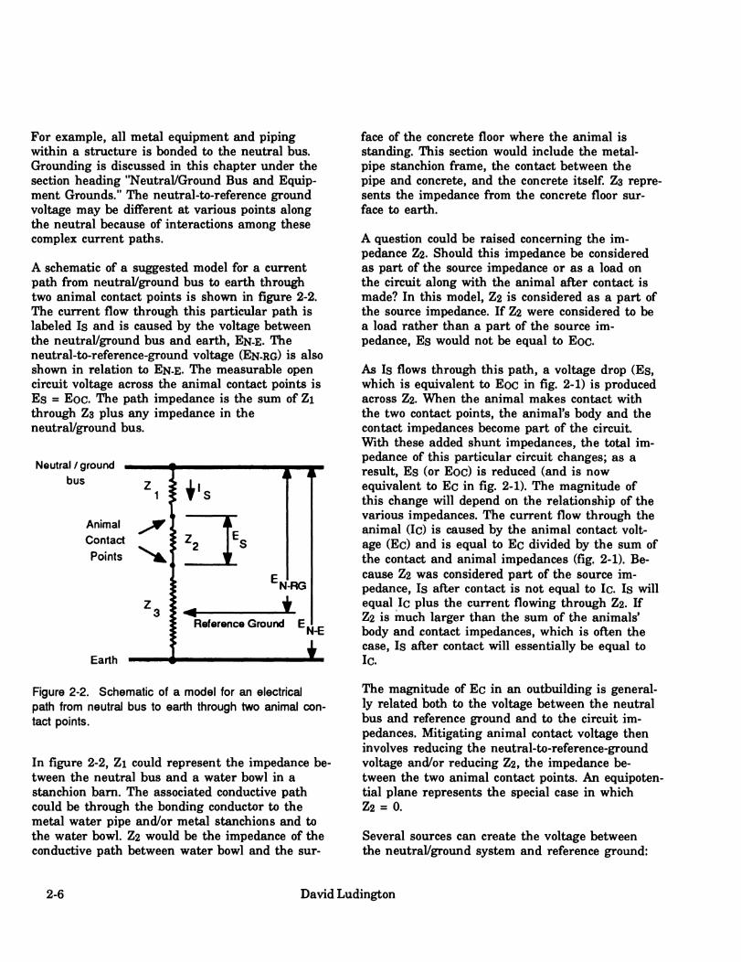
A schematic of a suggested model for a current path from neutral/ground bus to earth through two animal contact points is shown in figure 2-2. The current flow through this particular path is labeled Is and is caused by the voltage between the neutral/ground bus and earth, EN-E. The neutral-to-reference-ground voltage (EN-RG) is also shown in relation to EN-E. The measurable open circuit voltage across the animal contact points is Es = Eoc. The path impedance is the sum of Zi through Z3 plus any impedance in the neutral/groimd bus.
Neutral/ground bus
Animal Contact
Points
Earth
face of the concrete floor where the animal is standing. This section would include the metal- pipe stanchion frame, the contact between the pipe and concrete, and the concrete itself. Z3 repre- sents the impedance from the concrete floor sur- face to earth.
A question could be raised concerning the im- pedance Z2. Should this impedance be considered as part of the source impedance or as a load on the circuit along with the animal after contact is made? In this model, Z2 is considered as a part of the source impedance. If Z2 were considered to be a load rather than a part of the source im- pedance. Es would not be equal to Eoc
As Is flows through this path, a voltage drop (Es, which is equivalent to Eoc in fig. 2-1) is produced across Z2. When the animal makes contact with the two contact points, the animal's body and the contact impedances become part of the circuit. With these added shimt impedances, the total im- pedance of this particular circuit changes; as a result. Es (or Eoc) is reduced (and is now equivalent to Ec in fig. 2-1). The magnitude of this change will depend on the relationship of the various impedances. The current flow through the animal (Ic) is caused by the animal contact volt- age (Ec) and is equal to Ec divided by the sum of the contact and animal impedances (fig. 2-1). Be- cause Z2 was considered part of the source im- pedance. Is after contact is not equal to Ic. Is will equal Ic plus the current flowing through Z2. If Z2 is much larger than the sum of the animals' body and contact impedances, which is often the case. Is after contact will essentially be equal to Ic.
Figure 2-2. Schematic of a model for an electrical path from neutral bus to earth through two animal con- tact points.
In figure 2-2, Zi could represent the impedance be- tween the neutral bus and a water bowl in a stanchion bam. The associated conductive path could be through the bonding conductor to the metal water pipe and/or metal stanchions and to the water bowl. Z2 would be the impedance of the conductive path between water bowl and the sur-
The magnitude of Ec in an outbuilding is general- ly related both to the voltage between the neutral bus and reference ground and to the circuit im- pedances. Mitigating animal contact voltage then involves reducing the neutral-to-reference-ground voltage and/or reducing Z2, the impedance be- tween the two animal contact points. An equipoten- tial plane represents the special case in which Z2 = 0.
Several sources can create the voltage between the neutral/ground system and reference groimd:
2-6 David Ludington

the voltage drop in the secondary neutral system; currents in the grounding conductor; and load, leakage, or fault currents in the primary or secon- dary grounding resistances.
Voltage Drop in Secondary Neutral
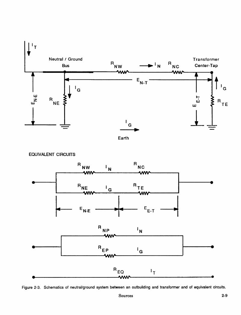
Voltage drops due to currents in the farm secon- dary-neutral/grounding systems and the grounding resistances are a source for stray voltages. A schematic of the secondary neutral conductor and earth circuit between the neutral bus in an out- building and the center tap of the farm distribu- tion transformer is shown in figure 2-3. Definitions of terms used in figure 2-3 and in sub- sequent discussions are listed below. Also shown are the equivalent circuit diagrams. The direction of instantaneous current flow and voltage drop is dependent on the neutral-to-reference-groimd vol- tages at the transformer center tap and at the neutral/ground bus point. (The equipment-ground- ing conductors are not shown in this simplified diagram; it is presumed they are carrying no leakage or fault current, and thus not producing a voltage drop. The grounding system would have a voltage to earth corresponding to the neutral-to- earth voltage at the point of connection.)
The following simplified example applies when the neutral bus has a higher potential than the
transformer center tap. The actual current flows and voltages would depend on many factors includ- ing other service drops fiî'om the transformer and the presence or absence of a primary grounded neutral. The purpose of this example is to il- lustrate the factors involved, even in a simplistic case, in the division of current at the neutral bus and center tap and the impact of changes in selected circuit impedances.
The current, IT, will divide at the bus into a cur- rent flow in the neutral conductor (IN) and a cur- rent flow in the ground (IG), the magnitude of each being a function of the impedances of the two paths. The current flowing to earth. IG, is fiir- ther divided among all the paths to ground, with even further division as the currents proceed toward earth. The magnitudes of some of the cur- rents in these individual paths will be small but they cannot be ignored.
The current. IG, is the sum of the current flows in all paths from the neutral bus through earth to either 1) the primary neutral via the transformer groimd or other primary neutral grounds (wye dis- tribution) or 2) the transformer groimd (delta dis- tribution). For simplicity the schematic shows all the ground current returning via the transformer ground. Because of the voltage drops across the impedances, which are shown as resistances RNW,
Definitions of terms used in figure 2-3 and in following discussions
RNE = resistance paths to earth at the bus end of the neutral. RTE = resistance between the transformer center tap and earth. Rj^^ = resistance of the neutral conductor. RNC = resistance of all connectors along the neutral conductor. RNP = total resistance of neutral path. REP = total resistance of earth path. REQ = equivalent resistance of circuit. IT = imbalanced load and fault current returning to neutral bus via the equipment grounds and other
bonded equipment or current entering from the primary neutral. IQ = current flow through earth path. IN = current flow through neutral conductor. EN-T = voltage between bus and transformer center tap. EN-E = voltage between the neutral/ground bus and earth. EE-T = voltage between the earth and center tap of the transformer.
Sources 2-7

RNC, RNE, and RTE, there will be a voltage dif- ferential between the bus and the transformer cen- ter tap. The magnitudes of individual voltage drops are dependent on current flow and impedan- ces.
To better illustrate many of the concepts needed to xmderstand the cause for stray voltage, values will be given to the variables. (Note: resistances are used in place of impedances so that the ex- ample can be followed more easily.) Two cases will be considered:
♦ Where resistance of neutral connectors, RNC, is zero.
♦ Where RNC is 0.5 ohms (Í2), because of poor connections.
Assume the following values: IT = 20 amperes (A), RNE = 3.0 Í2, RTE = 25 fí, and RNW = 0.076 Í2 (150 feet, AWG #4 aluminum). The results of several calculations are shown in table 2-1.
The equivalent resistance (REQ) of the two paral- lel circuits between the neutral bus and the transformer's center tap is dominated by the resis- tance of the neutral conductor path. With the poor connectors in the neutral conductor path, the resis- tance of the neutral path (RNP) is 0.58 ß; the resistance of the earth path is 28 Í2. These two resistances in parallel have an equivalent resis- tance (REQ) of 0.56 Í2, which is slightly less than RNP. The equivalent resistance of resistances in
Table 2-1. Values of selected parameters for two values of RNC
Value RNC = o.on RNC = 0.5 fí
REQ (ft) 0.076 0.56 EN.T(V) 1.52 11.29 IN (A) 19.95 19.60 IG (A) 0.05 0.40 EN-E(V) 0.16 1.21 EE-T(V) 1.35 10.18
Rules for significant figures have been ignored so that the sum of the parts will more nearly equal the total. There is some rounding error.
parallel is always less than the smallest in- dividual resistance. Unless the neutral conductor is open, REQ will be slightly less than RNP.
With the current flow in the neutral conduc- tor/earth system from the neutral bus to the trans- former (IT) equal to 20 A and the neutral conductor path at the lower resistance, the volt- age between the neutral bus and the center tap of the transformer (EN-T) would be about 1.5 volts (V). When the resistance of the poor connectors is added to the resistance of the neutral conductor this voltage increases to 11.3 V. This voltage ap- pears across both paths — neutral conductor and earth — and at the equipment grounding conduc- tor at the neutral/ground bonding point.
^The actual farm case will have a multigrounded secondary system with several neutral/ground return conductors, ser- vice-entrance grounding points, and ground contacting equipment. The return load and/or leakage/fault currents will divide among the neutral, the grounding conductors, the grounding resistances, and the earth according to their rela- tive admittances (inverse of impedances) to return to the transformer center tap. These form complex current paths and the voltages measured between two different points will generally not be the same. The multigrounded primary neutral has the same problems of neutral conductor impedance, connector resistances, and variable grounding resis- tances; with load, leakage and fault currents injected at various locations along the primary line. Other secondary sys- tems also may contribute their problems due to secondary-primary neutral interconnections. As any wire, including the primary neutral, has a finite impedance, the resulting current flow gives rise to various voltage drops along the primary neutral conductor and from this conductor to earth. This effect (again simplified) is discussed in detail in the examples in the appendix of chapter 4, "Mitigation". It must be remembered that where the primary and secondary neutrals are connected together at the transformer center tap, the two neutrals at the point of connection are always at the same voltage relative to earth. If there is no primary neutral, or if the primary and secondary neutrals are iso- lated, the two neutrals can be at different voltages.
2-8 David Ludington
i''
T LÜ
Lii
Neutral / Ground
Bus
1 NE
R NW
"N-T
Earth
N NC
Transformer
Center-Tap
■A/VSA/^
fít LU
R TE
EQUIVALENT CIRCUITS
EQ
Figure 2-3. Schematics of neutral/ground system between an outbuilding and transformer and of equivalent circuits.
Sources 2-9

The division of current at the neutral bus is inver- sely proportional to the resistances of the two paths, i.e., neutral conductor and earth. Most of the current flows through the neutral path where the resistance is much lower: over 19.5 A versus less than 0.5 A. This same relationship between current and resistance will govern the amount of current that will flow through each of the many paths between the neutral bus and earth. We should be reminded of the saying, "Electricity al- ways takes the path of least resistance." This statement is often taken to mean that all the cur- rent takes the path of least resistance. This is wrong. "More current will take the path of lower resistance" is more accurate.
The total voltage difference between the neutral bus and transformer (EN-T) will be divided be- tween the neutral-to-earth connection (RNE) and transformer-to-earth connection (RTE). The EN-E voltage produced by conditions on the secondary side of the transformer is a function of the follow- ing factors:
♦ Current flow (imbalance, fault, other) in the neutral/earth system.
♦ Impedance of the neutral/earth circuit.
♦ Relationship between the impedances of the neutral-to-earth connection and the trans- former-to-earth connection.
The voltage along the neutral bus to the trans- former increased from 1.5 V to 11.3 V when the connector impedance was added. These voltages are the same irrespective of path, i.e., across the neutral conductor or the earth. In the earth path, about 10 percent (3/28) of the total voltage change occurs at the neutral-to-earth connection because the impedance at this point is about one-tenth (3 vs. 25 Í2) of the impedance at the transformer cen- ter tap. As a result of the poor connection, the EN- E voltage increased over seven times, from about 0.16 V to about 1.2 V. The magnitude of this in- crease vividly demonstrates how one simple prob- lem in the electrical distribution system has the possibility of creating a stray voltage/current prob- lem. A sevenfold increase in the EN-E will produce
a sevenfold increase in any contact voltage whose source is the EN-E.
The above example clearly demonstrates that problems with the secondary neutral conductor can easily produce a stray voltage/current prob- lem. It is important to keep the resistance of the secondary neutral as low as feasible. It is also im- portant to keep current flow in this conductor as low as possible to reduce the chance of producing a stray voltage/current problem should the resis- tance of the conductor increase over time. In the example, the increase in resistance resulted from failure of a connector. Such increases are common with corroded connectors.
Neutral/Ground Bus and Equipment Grounds
The neutral/ground bus at. the farm service entrance is the junction for all parts of the groimded neutral system of the secondary. In the wiring system for a farmstead, as stipulated in the National Electrical Code of 1990, Section 250- 50 (a), the equipment grounding conductors must be bonded to the neutral and to the grounding electrode conductor at the main service-entrance panel. The neutral and equipment grounding con- ductor must also be grounded at other building panels on the farm and at the distribution trans- former. The electrical system and supply equip- ment must be grounded according to the National Electrical Code, section 250-42. (Separation of grounding and neutral conductors at a building panel is sometimes allowed accrding to a specific exception for agricultural buildings; see below.)
A separate wire (conductor) should be used for equipment grounding, although vmder certain cir- cumstances, a metal sheath of a cable or a metal raceway (such as a rigid steel conduit) may be used as the equipment grounding conductor. In any case, the grounding conductors are connected to the grounded neutral conductor and the ground- ing electrode at the building service entrance. The equipment grounds are intended to carry small capacitively coupled or leakage currents or heavy current only in the event of a fault. (Some localities may permit/require separation of neutral and grounding conductors at the outbuilding ser- vice entrance or subpanel. Thus, these conductors
2-10 David Ludington

remain separate and are carried independently to the main service entrance, where they are bonded; see chapter 4, "Mitigation.")
Figure 2-4 illustrates a neutral/ground bus in a building service entrance showing the many parts that are joined together at the bus. The secondary neutral conductor is joined to the white (neutral conductor) current canying conductors for the 120- V circuits; the grounding electrode conductor; equipment grounding conductors (green or bare wires); and bonding conductors to water pipes, panel boxes, and other metal objects. The path from the neutral/ground bus to earth will be via the groimding electrode; the bondings to water pipes, etc.; and some of the electrical equipment groimds, such as those going to motors on the gut- ter cleaner and electrically heated stock waterers. These several paths, with individual impedances, are in parallel. The neutral-to-earth resistance (RNE) in figure 2-3 represents the equivalent im- pedance of all these parallel paths.
^^ Transformer Î Center-Tap
Secondary Neutral Conductor
Neutral / ground bus
Grounding Electrical Bonding (neutral) electrode equipment to pipes, Conductors conductor grounding other metallic (120 V circuits)
conductors objects
Figure 2-4. Schematic of neutral/ground bus with at- tached conductors and bonds.
Voltage Drop in Equipment Grounds Equipment groimds (green or bare wires) are re- quired to prevent shocks due to faults in electrical equipment. Equipment grounds are intended to provide a low-resistance return path for fault cur- rent, thus causing an overcurrent device to trip/open and prevent a voltage from developing between exposed metal parts of electrical equip- ment and earth. Equipment grounding conductors
are supposed to carry current only when there is a fault. Figure 2-5 shows a branch circuit with a properly installed equipment ground. The equip- ment groimding conductor is shown attached to the neutral/ground bus at the service entrance panel. The National Electrical Code requires that equipment grounding conductors (green or bare) and the neutral (white) conductor be separated at all points beyond the breaker panel of the main service entrance in an outbuilding.
Figure 2-5. A branch circuit with power conductors (B&W) and equipment ground (G) properly connected.
The frame of the electric equipment in figure 2-5 is shown as being isolated fi*om earth. If the equip- ment frame and earth were the two animal con- tact points, the value of the impedance Z2 in figure 2-2, would be very high. Under normal con- ditions, there would be essentially no current flow in the equipment grounding conductor and the fi*ame would take on the same potential with respect to earth as the neutral bus. Due to a low value of the resistance of the equipment groimd- ing conductor, the animal contact voltage (Ec) would be nearly equal to the neutral-to-earth volt- age if the animal's feet were at earth potential (i.e., Z3 = 0). If the animal were standing on con- crete or a wooden floor (Z3 greater than 0 but less than infinity), the contact voltage would be less than the neutral-to-reference-groimd voltage be- cause of the voltage drop across Z3.
Sources 2-11

Often the frame of electrical equipment is not iso- lated from earth, and there is a current path to ground/earth. Such equipment would include a gut- ter cleaner, condensing units on a milk tank, a milk pump, and a domestic water pump. Figure 2-6 illustrates such a situation. The im- pedance of this path is shown as RG. Referring to figure 2-2, Z2 can be low.
N
Figure 2-6. A branch circuit with power conductors (B&W) and equipment ground (G) properly connected. A connection (RQ) between the equipment and earth exists.
the equipment and the magnitude of the resulting current is sufficient to cause a response.
Leakage or Fault Current on an Equipment Ground Leakage or fault currents will produce a voltage drop along the equipment grounding conductor. For example, a 10-A fault current in 50 feet of #12 copper conductor will result in a voltage drop of 0.9 V. It is important to maintain low-resis- tance equipment grounds. Corrosive environments in livestock facilities can deteriorate electrical con- nections. Such deterioration can cause excessive voltage drops along the grounding conductor and increase the chances of establishing a stray volt- age/current problem. Periodic inspections and maintenance are essential to preserve the integrity of electrical systems.
Figure 2-7 illustrates the effect of a piece of equip- ment with an electrical fault. The equipment is in contact with the earth. Part of the fault current, IFI, is shown returning to the neutral bus via the equipment grounding conductor. The remaining fault current, IF2, returns via an earth path. Dif- ferences in current magnitudes affect the voltage drop between the equipment frame and the neutral bus.
With the equipment ground conductor connected to the neutral/groimd bus and to the equipment frame, and with a path to earth, there will be a current flow (shown as IG' in fig. 2-6) whenever there is a neutral-to-reference-groimd voltage. This current flow will be accompanied by a volt- age drop that will be divided between the equip- ment grounding conductor and the drop across RG. The voltage drop across RG would equal the open circuit voltage (Eoc). There could be little voltage drop along the equipment ground conduc- tor.
Figures 2-5 and 2-6 show proper wiring and no faults. Even so, a possible animal-contact voltage directly proportional to the neutral-to-reference- ground voltage does exist between the equipment and ground. A stray voltage/current problem will exist only if animals can come into contact with
ii SERVICE
ENIRANCE I ; LOAD^FAULTCURRENT
Figure 2-7. Fault in properly wired equipment causes fault current to flow toward transformer.
Considered by itself, this voltage drop in the equip- ment grounding conductor would raise the open
2-12 David Ludington

circuit voltage, Eoc However, this voltage drop together with the changes in the secondary neutral current (discussed earlier) may result in an increase or decrease of the open circuit volt- age, depending on their relative magnitudes and phase relationships. The resulting open circuit volt- age will appear as a voltage (ENE) between the faulty equipment and earth and could be accessed by animals through any conductive path to the faulty equipment. The lower contact voltage (Ec) would be measured on animal contact.
Excessive Secondary Neutral Current
B ^
I «5A B
j BN
N •-
-
I^-OA
El BR
^^ i »o" R •—» Ï
5A
(A) Balanced Load
Excessive current, IT, flowing in the secondary neutral system of a service drop can result from several factors, including 1) imbalance of the 120- V electric loads in the outbuilding, 2) the phase relationship between the various currents, e.g., im- balance, fault, and primary neutral (fig. 2-3), 3) electrical faults, and 4) improper wiring.
Unbalanced 120'V Loads Unbalanced 120-V loads in an outbuilding can have a major effect on the voltage measured be- tween the neutral bus and a reference ground. A three-conductor service drop to a farmstead is il- lustrated in figure 2-8. The two ungrounded con- ductors are labeled B and R, and the neutral conductor is N. The voltages EBN and ERN are 120 V and EBR is 240 V. Figure 2-8A shows two 600-W resistive loads, one across EBN and one across ERN. Both loads are on at the same time. The current flow in conductors B and R is at 5.0 A, and that in conductor N is 0.0 A. The reason the current in the neutral is 0.0 A instead of 10.0 A is that voltages EBN and ERN, and thus the cur- rents IB and IR, are out of phase by 180 degrees. Therefore the two current flows of 5.0 A, which meet at point X, cancel each other rather than add together. This is an example of balanced loads, i.e., no neutral current flow. If one load had an inductive or capacitive component, there would have been a phase shift in the current. As a result, the two currents IB and IR would not have canceled completely, and the neutral conductor would have carried a small current. IN.
Figure 2-8B shows the same circuit arrangement except with three 600-W loads, two across EBN
B #-
I «10A B
N •<
I^.SA
R •-
I^.SA
(B) Unbalanced Load
Figure 2-8. Three-conductor 120/240-V secondary dis- tributions with balanced (A) and unbalanced (B) loads. Each load is 600 W.
and one across ERN. The current flows have changed. Now current flow is 5.0 A in conductor R but 10.0 A in conductor B and 5.0 A in N. The cur- rent flow in conductor B is now only partially can- celed by the current in R, with the remainder flowing in conductor N. This circuit is unbalanced. The current flow in the neutral conductor is 5.0 A, the difference between the current in conduc- tors IB and IR. Balancing 120-V loads as nearly as possible, including the times they are on, will reduce the secondary neutral current and the resulting voltage drop.
Phase Relationships The phase relationship between the secondary neutral current and the primary neutral current
Sources 2-13

has a direct bearing on the voltage between the neutral bus and a reference ground for a single- phase service. When primary and secondary are both single-phase systems, these two currents can be in phase or 180 degrees out of phase; thus, the voltage drop in the secondary neutral can be in phase or 180 degrees out of phase with the primary neutral. In reality, these relationships are more complicated than this statement suggests. The use of inductive loads, such as motors and high intensity discharge lamps (mercury vapor or high pressure sodium), causes phase shifts be- tween current and voltage that are less than 180 degrees. These shifted voltages do not directly add or subtract.
When two or more currents or voltage drops com- bine at a junction, the resulting current or voltage is always the vector sum of the components. If two voltage drops are involved and are in phase, they will add, and the voltage between the neutral bus and a reference ground will increase. If the two are 180 degrees out of phase, the vec- tor sum will be smaller than the larger com- ponent and perhaps smaller than both components. If the two voltages are out of phase by less than 180 degrees^, the vector sum will lie between these two extremes. The high starting currents associated with motors mean that there will often be momentary high currents (and vol- tages), called transients, on the system.
A true delta primary distribution has no primary neutral conductor and, thus, no primary neutral current. Therefore the secondary neutral current (voltage drop) is independent of primary distribu- tion and occurs because of conditions on the farmstead.
Fault or Leakage Currents Undesired current will occasionally flow when a conductor - hot (black or red) wire, neutral (white) wire, or electrical equipment (e.g., a heat- ing element in a water heater) - makes electrical contact with an object which is at a lower poten- tial. The contact may be the result of a fault (i.e., direct contact) or leakage, e.g., via dirt and mois- ture. Leakage may also result from capacitive cou- pling. Coupling is discussed in this chapter under the heading "Coupled Voltage/Current." In general.
a conductive pathway to an area of lower poten- tial must exist before any current can flow. This path may be another wire or a grounded material which is in direct contact with the defect. Alterna- tively, moisture and dirt around the defect may provide a conductive path to earth. Common causes of fault or leakage currents are old equip- ment, improper wiring, and poor maintenance of electrical equipment. In addition, water heaters, buried cables or equipment, and submersible water pumps are especially susceptible to damage which results in current leakage or faults.
The severity of the problem, i.e., the amoimt of current flow, depends on the impedance of the path and location of the problem. A ''dead short" would have a very low impedance and would most likely trigger protective fuses or circuit breakers. In contrast, a crack in insulation surroimded by moist cobwebs could have a high impedance to earth and result in a small current flow.
The location of the problem within a piece of equipment is also important. In a 120-V electric heater, for example, a fault involving the black (hot) wire would be more serious than the same kind of fault involving the white neutral wire. This is because the black wire is never groimded, which means that the voltage in the black wire relative to earth approaches 120 V. The voltage in the white wire relative to earth will be similar to the neutral-to-reference-ground voltage at the ser- vice entrance, because the white wire is the neutral conductor.
Fault or leakage currents must return to the cen- ter tap of the distribution transformer. Depending on the phase relationship between these currents and any secondary-neutral imbalance current, the secondary-neutral voltage drop may be increased or decreased. In other words, fault or leakeige cur- rents can improve or worsen the current balance on the secondary neutral and, thus, the voltage be- tween the neutral bus and a reference ground. It is best to minimize leakage currents.
Fault Current to Earth: If a fault to earth occurs, the leakage or fault current will return to the transformer's center tap via the grounding conduc- tors and also via the secondary and primary
2-14 David Ludington
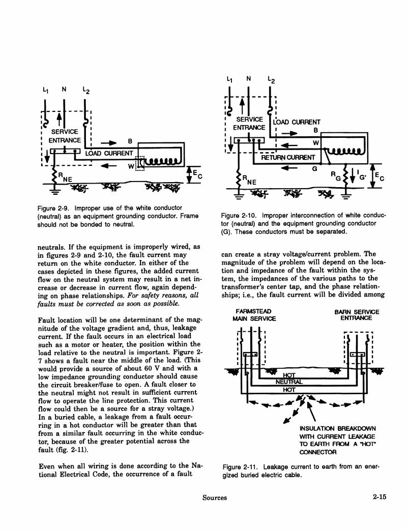
N
B
LOAD CURREhfT
Wi n 1 ,^ sMjjF ^p^r E
Figure 2-9. Improper use of the white conductor (neutral) as an equipment grounding conductor. Frame should not be bonded to neutral.
neutrals. If the equipment is improperly wired, as in figures 2-9 and 2-10, the fault current may return on the white conductor. In either of the cases depicted in these figures, the added current flow on the neutral system may result in a net in- crease or decrease in current flow, again depend- ing on phase relationships. For safety reasons, all faults must be corrected as soon as possible.
Fault location will be one determinant of the mag- nitude of the voltage gradient and, thus, leakage current. If the fault occurs in an electrical load such as a motor or heater, the position within the load relative to the neutral is important. Figure 2- 7 shows a fault near the middle of the load. (This would provide a source of about 60 V and with a low impedance grounding conductor should cause the circuit breaker/fuse to open. A fault closer to the neutral might not result in sufficient current flow to operate the line protection. This current flow could then be a source for a stray voltage.) In a buried cable, a leakage from a fault occur- ring in a hot conductor will be greater than that from a similar fault occurring in the white conduc- tor, because of the greater potential across the fault (fig. 2-11).
Even when all wiring is done according to the Na- tional Electrical Code, the occurrence of a fault
"¡^ 4r
Figure 2-10. Improper interconnection of white conduc- tor (neutral) and the equipment grounding conductor (G). These conductors must be separated.
can create a stray voltage/current problem. The magnitude of the problem will depend on the loca- tion and impedance of the fault within the sys- tem, the impedances of the various paths to the transformer's center tap, and the phase relation- ships; i.e., the fault current will be divided among
FARMSTEAD MAIN SERVICE
BARN SERVICE ENTRANCE
INSULATION BREAKDOWN WITH CURRENT LEAKAGE TO EARTH FROM A TIOT* CONNECTOR
Figure 2-11. Leakage current to earth from an ener- gized buried electric cable.
Sources 2-15
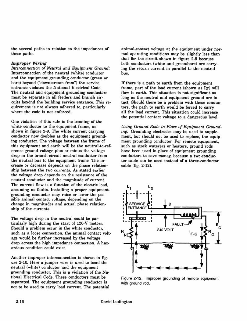
the several paths in relation to the impedances of these paths.
Improper Wiring Interconnection of Neutral and Equipment Ground: Interconnection of the neutral (white) conductor and the equipment grounding conductor (green or bare) beyond ("downstream from") the service entrance violates the National Electrical Code. The neutral and equipment grounding conductors must be separate in all feeders and branch cir- cuits beyond the building service entrance. This re- quirement is not always adhered to, particularly where the code is not enforced.
One violation of this rule is the bonding of the white conductor to the equipment frame, as shown in figure 2-9. The white current carrying conductor now doubles as the equipment ground- ing conductor. The voltage between the frame of this equipment and earth will be the neutral-to-ref- erence-ground voltage plus or minus the voltage drop in the branch-circuit neutral conductor fi-om the neutral bus to the equipment frame. The in- crease or decrease depends on the phase relation- ship between the two currents. As stated earlier the voltage drop depends on the resistance of the neutral conductor and the magnitude of current. The current flow is a fimction of the electric load, assuming no faults. Installing a proper equipment- grounding conductor may raise or lower the pos- sible animal contact voltage, depending on the change in magnitudes and actual phase relation- ship of the currents.
The voltage drop in the neutral could be par- ticularly high during the start of 120-V motors. Should a problem occur in the white conductor, such as a loose connection, the animal contact volt- age would be further increased by the voltage drop across the high impedance connection. A haz- ardous condition could exist.
Another improper interconnection is shown in fig- ure 2-10. Here a jumper wire is used to bond the neutral (white) conductor and the equipment groimding conductor. This is a violation of the Na- tional Electrical Code. These conductors must be separated. The equipment grounding conductor is not to be used to carry load current. The potential
animal-contact voltage at the equipment under nor- mal operating conditions may be slightly less than that for the circuit shown in figure 2-9 because both conductors (white and green/bare) are carry- ing the return current in parallel to the neutral bus.
If there is a path to earth fi*om the equipment frame, part of the load current (shown as IGO will flow to earth. This situation is not significant as long as the neutral and equipment ground are in- tact. Should there be a problem with these conduc- tors, the path to earth would be forced to carry all the load current. This situation could increase the potential contact voltage to a dangerous level.
Using Ground Rods in Place of Equipment Ground- ing: Grounding electrodes may be used to supple- ment, but should not be used to replace, the equip- ment groimding conductor. For remote equipment, such as stock waterers or heaters, ground rods have been used in place of equipment grounding conductors to save money, because a two-conduc- tor cable can be used instead of a three-conductor cable (fig. 2-12).
Figure 2-12. Improper grounding of remote equipment with ground rod.
2-16 David Ludington
Such a use of ground rods does not meet National Electrical Code requirements and can lead to haz- ardous contact voltages — up to 120 V — for both animals and humans should a fault occur. The seriousness of the problem will depend on the loca- tion and impedance of the fault and the im- pedance of the earth path. Fault current will flow in the earth, where it may cause serious, touch or step voltages for animals and humans at the waterer. In addition, because of the grounding resistance, fuses or circuit breakers may fail to operate.
Coupled Voltage/Current
Conductive materials which are electrically iso- lated from ground can acquire a voltage with respect to a reference ground. This voltage can ap- pear as a result of capacitive or inductive cou- pling. It can also appear as a result of a high-resistance leakage path from the power lines, or, for example, from a pulsating high-voltage source, such as a cow trainer or electrified fence. Cow trainers consist of a single wire; thus, the electric field around the wire is much higher than that around a 120- or 240-V branch circuit cable. Branch circuit cables have two conductors in close proximity. Because the "out" and "back" current flow through the two conductors, the magnetic field of one conductor cancels most of the mag- netic field of the other conductor. Thus, the resul- tant magnetic field around the cables is low.
Voltages can be capacitively coupled when a single conductor carrying an alternating or pulsating volt- age rims parallel to electrically isolated conductive materials. For example, voltage might be induced in an isolated stainless steel milk pipeline which is parallel with a cow trainer located above the cows in a stanchion barn.
Because the voltage is the result of coupling rather than direct contact with an electrical supp- ly, the source impedance for the milk pipeline, for example, would be very high. Therefore the capabilities of producing current levels sufficient to cause problems are rare. Depending on the capacitance of the item in question and its level of isolation, there may be enough stored energy to cause a problem when an animal shorts or dischar-
ges the energy from the item to ground. There would, however, be little sustained current flow.
Step Potentials
Current flowing through the resistance of the earth can set up a potential (voltage) gradient across the earth surface. The potential is highest near the contact point where the current enters the earth. The voltage between two points (as from front to rear hooves of an animal) depends on the current and resistance of the path between those points (the hooves). The resistance increases with increasing distance between points of con- tact. Normally a heavy current such as might originate from a power fault or lightning strike and close proximity of an animal to the current source are needed to result in the flow of a dangerous current through the animal. The step potential decreases rapidly away from the earth- current contact point. This decrease is the basis for designs of step-potential gradient zones com- monly used with equipotential planes.
Caveat
Only if a voltage which the animal contacts (Ec) is sufficient to produce a current at a level of con- cern, is it then necessary to make the appropriate measurements to determine the source(s) and devise a mitigation process.
Power Delivery Systems
Another origin of stray voltage/current problems is an elevated voltage between the primary neutral and earth. "Neutral-to-earth" voltage is the name given to the voltage measured between the multi- groimded neutral system (generally the neutral bus at the service entrance) and earth. This volt- age is estimated by measuring the voltage be- tween the neutral/ground bus and a reference (isolated) ground rod. The accuracy of the es- timate depends on the location of the reference ground and the measurement system. "Neutral-to- reference ground voltage" is a more accurate
Sources 2-17

Items in a delivery system for electric power
Generation Transmission Substation Primary distribution (three- and single-phase) Customer's transformer Secondary distribution
Utility service drop (three- and single-phase) Meter Feeders to buildings Service entrance conductors Service equipment/distribution panel
Gocation of secondary neutral/ground bus) Branch circuits and feeders Appliance/load
name for what is being measured and will there- fore be used for the remainder of this section.
Stray voltage should not be equated with neutral- to-reference-ground voltage. The reason is that animals would not normally make simultaneous contact with the primary multigrounded neutral system and the reference groxmd. The actual con- tact voltage is generally a fraction of the neutral- to-reference-ground voltage and depends on the impedances of the current paths between the animal, the neutral/groimding bus, and earth.
To understand the causes of elevated neutral-to-ref- erence-ground voltages, relations among the electric-power distribution system and the farmstead electrical system must be understood. The delivery system which brings electric power from the generation plant to the customer's ap- pliance is made up of many components. Not all systems have the same components, but the follow- ing list contains most of the major items.
The words "primary" and "secondary" are used in discussing distribution of electric power. The im- plication is that primary voltages are higher than secondary voltages, which are usually on the customer's side of the transformer. Distribution transformers commonly have a high-voltage (primary) side and a low-voltage (secondary) side.
The earlier parts of this chapter have dealt with the secondary system.
Power Generation and Transmission
Nearly all the commercial production of ac electricity is accomplished with three-phase synchronous alternators. These alternators produce three single-phase currents with 120 degrees between each phase. Most power used worldwide has a sinusoidal waveform of 50 or 60 hertz (Hz) (cycles per second). This generated power is transmitted at high voltages (up to and over 700 kilovolts (kV)) to substations, where the voltage is reduced for either subtransmission to a second substation or primary distribution. Vol- tages of primary distribution lines are usually less than 35 kV phase to phase.
Primary Distribution
Primary distribution lines deliver power from the substation to the customer's transformer. These lines are normally owned by public or private utility companies. Three-phase wye (Y), three- phase delta (A), and single phase are the most common configurations used for primary distribu- tion of electric power. From the substation, a three-phase primary could go directly 1) to a large customer, 2) to supply single-phase power to smaller customers, or 3) to serve as a feed to single-phase primary-distribution branches.
Wye Distribution A three-phase wye primary distribution with a multigrounded neutral system uses four conduc- tors (fig. 2-13). Three of the conductors (A, B, and C) are ungroimded phase (hot) conductors. The fourth conductor (N) is a groxmded neutral conduc- tor. This primary neutral is grounded at intervals along the distribution line and at each trans- former. A single-phase primary distribution with two conductors, one ungrounded (B) and one grounded (N), is shown branching from the three- phase line. Other single-phase branches could be taken from conductor A, B, or C and N. To reduce current flow in the neutral, the utility will try to balance the load on the three ungrounded conduc- tors by choosing which ungrounded conductor to use for individual service drops or for single-phase
2-18 David Ludington

SUBSTATION
(SECONDARY SIDE OF
TRANSFORMER) PRIMARY DISTRIBUTION
3 PHASE. 4 CONDUCTOR
UL JULuJ prrpnn
I 120 1120
240 V
B
N 1 PHASE. 2 CONDUCTOR
T ÜUUJ JuJ nnrpnr
SECX>NDARY DISTRIBUTION
SINGLE PHASE SERVICE DROPS TO FARMSTEADS
I r— I
120 1120
240 V
B
N
Figure 2-13. Multigrounded neutral distribution system (wye).
branches. From a practical standpoint, it is impos- sible to cancel (balance) all neutral currents. Varia- tions in use of electricity by time of day, differences in phases of loads at individual user sites, and the variable spacing of users along the distribution mean that there will be different neutral currents along the neutral.
Delta Distribution A true three-phase delta (A) primary system uses three conductors (fig. 2-14). All of the conductors are ungroimded (hot) conductors. There is no grounded primary neutral. A single-phase primary distribution branch attached to conductors A and C is also shown. Again, the utility will try to balance loads on the three primary-phase conduc- tors by choosing the appropriate pair of conduc- tors for all single-phase hnes and services.
Open Delta Distribution A third, less common, type of three-phase primary distribution is the open delta, or V phase, which has two imgroimded phase conductors and a groimded primary neutral (fig. 2-15). The secon- dary consists of a single-phase service drop (B,N,C 120/240 V) which uses a single transformer and three conductors. A single-phase service drop (C,N,B 120/240 V) and a three-phase service drop (A,C,B 120/240 V) can be provided by using two transformers and four conductors. There may or may not be bonding between the primary and secondary neutrals.
Single-Phase Service Drops
Service drops take power from the secondary side of the transformer to the electric meter. Single- phase (120/240-V) power can be obtained from either a three-phase or single-phase primary. In
Sources 2-19
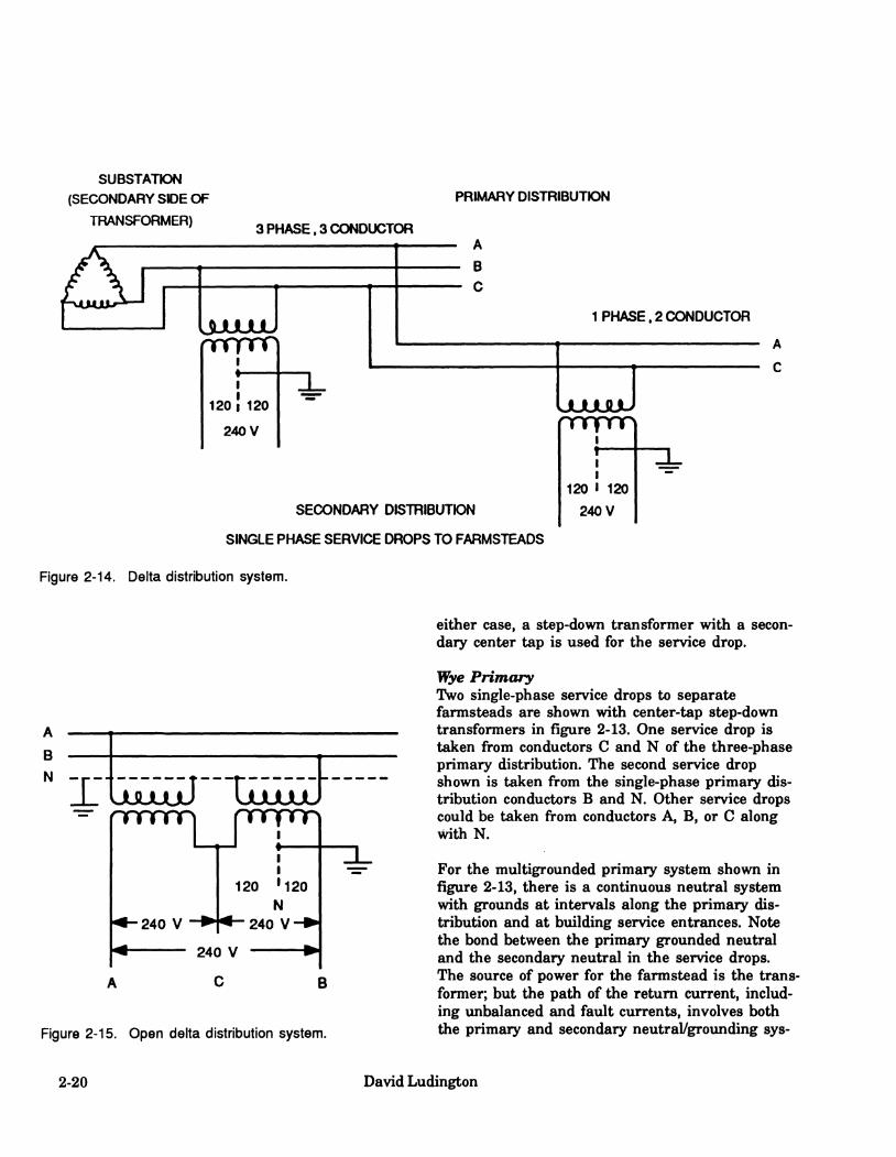
SUBSTATJON (SECONDARY SDE OF
TRANSFORMER)
PRIMARY DISTRIBUTION
3 PHASE. 3 CONDUCTOR
IjuuuuU rrmnn
A
B C
1 PHASE. 2 CONDUCTOR
120 ! 120
240 V
SECONDARY DISTRIBUTION
SINGLE PHASE SERVICE DROPS TO FARMSTEADS
uuuuuJ nrrpnri
r—— I I
120 I 120 240 V
Figure 2-14. Delta distribution system.
B
N - r JLflJUuJ ULIUU^
Figure 2-15. Open delta distribution system.
either case, a step-down transformer with a secon- dary center tap is used for the service drop.
Yiye Primary Two single-phase service drops to separate farmsteads are shown with center-tap step-down transformers in figure 2-13. One service drop is taken from conductors C and N of the three-phase primary distribution. The second service drop shown is taken fi^om the single-phase primary dis- tribution conductors B and N. Other service drops could be taken fi-om conductors A, B, or C along with N.
For the multigrounded primary system shown in figure 2-13, there is a continuous neutral system with grounds at intervals along the primary dis- tribution and at building service entrances. Note the bond between the primary grounded neutral and the secondary neutral in the service drops. The source of power for the farmstead is the trans- former; but the path of the return current, includ- ing unbalanced and fault currents, involves both the primary and secondary neutral/grounding sys-
2-20 David Ludington

terns and earth. The farmstead distribution sys- tem is not isolated from the primary distribution. Neutral load or fault currents to neutral or ground at an adjacent farmstead(s) can affect the neutral-to-ground voltage of a farmstead. The primary and secondary neutrals will have the same voltage to reference ground at the point where they are bonded.
The earth is a return current path in parallel with the neutral conductor paths. These paths are not only in parallel but also interconnected at many points via the multiple grounds. According to the National Electrical Code, the neutral on a farmstead must be grounded at the transformer, main service (meter), and generally at the out- building service entrances for safety reasons. The amount of current flowing in each of these paths — earth and neutral conductor paths — will depend on their relative impedances. (The higher the relative impedance, the lower the current.) Under the excepted condition in which the primary and secondary neutrals are disconnected, the use of an approved surge protection device is required.
Voltage Between the Primary Neutral and a Reference Ground The magnitude of the voltage between the primary neutral and a reference ground is depend- ent on the voltage drop in the neutral system. Be- cause the primary/secondary neutral is groimded at each distribution transformer and the primary at intervals at distribution poles, some current pas- ses throxigh the grounding resistances. Thus there is an expected, usual, voltage to earth all along the line. This voltage will be different at various locations and will change constantly, depending on load changes and seasonal changes in earth resis- tance. The impedance of the neutral conductor depends both on the size of the conductor (resis- tive component) and the spacing from the other power conductor(s) (reactive component); thus there is a reasonable limit to a lowest impedance for the neutral.
The National Electrical Code and National Electri- cal Safety Code require that the primary and secondary neutrals be interconnected at the dis- tribution transformer for safety. (There is an excep-
tion whereby if an approved surge arrester is used, this requirement is waived.) One conse- quence is that at the point of interconnection, the neutral to earth voltage for the primary and secon- dary neutrals will be the same, i.e., the load, leakage, and fault currents, and the impedances in the primary and secondary neutrals; the secon- dary equipment-grounding system; and the ground- ing resistances, together, determine the observed voltage at the interconnection point. Any change in current in either system is likely to produce a change in this voltage. For example, changes in load at another farm or at a factory or residence may produce a change in the neutral-to-earth volt- age at a given farm. Thus, there can be secondary to secondary system effects due to interconnec- tions with the primary neutral, as well as effects from primary system changes. Depending on phase relationships of the currents, the neutral-to- earth voltage may increase or decrease. These in- teractions are discussed in detail in chapter 4, "Mitigation."
Consequences of interconnecting primary and secondary neutrals in three-phase distribution sys- tems are similar to those for single-phase distribu- tions. However, it is possible on a three-phase line (but not on a single-phase line) to rotate the dif- ferent single-phase loads to different phases. The neutral currents will tend to balance and thus reduce the magnitude of the neutral-to-earth volt- age along the line. (A balemced three-phase load does not contribute appreciably to neutral current.)
To solve difficult stray voltage problems at a farm, it is sometimes useful to temporarily disconnect the primary and secondary neutrals. This must be done only by the utility; a stray voltage expert should be present to interpret the electrical meas- urements made. The procedures for detecting and correcting problems are discussed in the chapters on measurements and detection, and on mitigation.
Delta Primary Two single-phase service drops (120/240 V) for farmsteads are shown in figure 2-14. They are shown originating from the three-phase and single- phase primary distribution lines. These drops begin on the secondary side of the transformer
Sources 2-21

and are the start of the secondary distribution net- work.
Additional Sources of Information
For the delta ungrounded primary system, the transformer isolates the farmstead distribution from the primary distribution system. There are no direct connections (bonding) of conductors. The transformer secondary windings become the power source for the farmstead, and therefore all im- balance and fault currents must return to the transformer directly via the secondary grounded neutral and earth system. The farmstead is not impacted by off-farm loads or faults except through changes in line voltages or through chan- ges in effective impedances to earth. However, be- cause system grounding is restricted to the farmstead, faults or unbalanced loads at the farmstead are likely to have a greater effect on the neutral-to-reference-groimd voltage for this dis- tribution system than for one in which the primary neutral is bonded to the secondary neutral.
For additional information, see Surbrook and Reese (1981), Cloud et al. (1987), and Ludington et al. (1987).
Three-Phase Service Drops
Some large farms use three-phase, four-wire ser- vice drops. These can be taken from either a three- phase primary wye or delta distribution system. Most commonly three transformers are used, one for each phase. The transformer windings are con- nected to form a wye. The three secondaries are also connected to form a wye, with the center point used for the neutral, thus yielding 120/208 V (fig. 2-16). Two or three transformers can also be connected to form an open or closed delta (fig. 2-16). One transformer has a center tap on the secondary side. The secondary neutral originates at this center tap and is bonded to the primary grounded neutral; both are grounded at the trans- former pole. This service would provide single- phase 120/240 V, and three-phase 240 V. In combined single- and three-phase systems, a larger transformer is needed to accommodate the added single-phase 120/240-V load.
2-22 David Ludington

Wye
208
208
Secondary
Delta
Secondary - Open, with 2 transformers
- Closed, with 3 transformers
Figure 2-16. Single- and three-phase secondaries derived from (top) a wye distribution and (bottom) a delta distribution. If the delta distribution is an open-delta distribution, the third transformer shown with dashed lines is not used; hence the term "open."
Sources 2-23
3. Physiological and Behavioral Effects Daniel J. Aneshansley and R. C. Gorewit, editors
Summary
Although cows and humans may be similarly sensi- tive to electric current, cows are more susceptible to stray voltages primarily because they have much lower body impedances (resistances) com- pared to humans. From Ohm's law, current is equal to voltage divided by impedance. Therefore, for a given voltage, a lower body impedance results in a larger current. Current level is of criti- cal importance because animals respond to the cur- rent passing through their bodies, and not directly to the voltage that generated the current
During electrical contact, it is actually the total series impedance that limits the current cows or humans receive and not just body impedance. The total series impedance is the sum of source, path, contact, and body impedances. Body plus contact impedances of cows are much lower than impedan- ces of humans. Furthermore, the wet environment in which cows are housed can accentuate differen- ces in contact impedances, e.g., cows standing in manure make better electrical contact with the earth than farmers wearing rubber boots. A lower body impedance plus lower contact impedances means that more current is delivered to a cow than to a human for a fixed voltage.
There are several sets of cow contact points or areas between which a cow is likely to contact voltage and allow a pathway for current. The im- pedances of most of these pathways have been studied. The path of least impedance is the mouth- to-all-hooves pathway. No studies have been reported on the effects of environmental conditions on contact impedance. However, it is known that water or wet environments allow better electrical contact (lower contact impedance). All reported measurements of cow impedances involved making some form of cow contact (certainly not stand- ardized) and therefore include a value, albeit some- what variable, for contact impedance.
The magnitude of current needed to elicit minimal behavioral responses is very similar to the mag- nitude of current that can just be perceived by
humans (0.5-2 mA). Because cows cannot tell a re- searcher when they perceive a current, re- searchers look for responses they can see or measure such as changes in behavior. The mini- mum current needed to cause cows to lifli their legs or open their mouths more often than they do normally can be as low as 0.5 mA to as much as 5 mA
The voltages needed to deliver these currents depend on the body impedance of the cow, the con- tact impedances between the cow and the conduc- tive structures, any impedance of the conductive structures, and the impedance of the voltage source. If the sum of these series impedances is as- sumed to range from 500 to 1,000 ohms, then the range of voltages over which a cow first perceives current (shows a minimal behavioral response) is 0.25 to 5 V. If the source impedance is high, in the thousands to millions of ohms, as from a leakage source, then much greater voltages are needed to provide currents that can be sensed. Older recommendations for tolerable levels of cow contact voltages (0.5 V (1980) and 0.7 V (1987)) were based on the lowest values for perceived cur- rents and low values for body, contact, path, and source impedances.
These past voltage recommendations need to be reviewed in light of recent research which indi- cates that when currents are below 6 mA for a short term (21 days), production, reproduction, and animal health are not affected; nor is there a significent effect on the levels of hormones natural- ly released during milking or in response to stress. Some moderate behavioral changes are evi- dent, however, at currents between 3 and 6 mA, and as currents approach 4 ma, these changes may require an additional investment of time from the dairy operator. When currents above 7 mA are delivered through the milk, milking machines are kicked off. Although there is no con- clusive evidence, it appears that behavioral chan- ges which might require additional labor could occur at voltages as low as 1.5 V (3 mA). How- ever, it also appears that the large majority of cows probably do not demonstrate problem be- haviors until voltages are about 3 or 4 V. These voltage estimates are based on total impedances of 500 or 1,000 ohms. Direct economic effects have
Physiological Effects 3-1

been shown at voltages of 4 V and above, but only in a small percentage of cases where animals refused to drink for 36 hours (6 out of 90 animals). For these six animals, production dropped rapidly during this period and significant health problems would have occurred if the animals had not been given alternate sources of water. Experiments involving long-term exposures of cows to voltage also indicate that cows ac- climate physiologically and behaviorally to con- stant and intermittent currents below 6 mA.
Based on current research, cow contact voltages from low impedance sources should be kept less than 2 to 4 V. Cow contact voltages between 1 and 4 V from low impedance sources may cause behavioral effects resulting in increased labor costs and/or inappropriate responses of farmers to the changes in behavior. These possible increased costs have to be balanced against the cost of reduc- ing voltages in the range of 1 to 4 V. Once cow contact voltages reach 1.0 V, a program of routine monitoring should be initiated to ensure that the voltages do not increase significantly.
Attempts have been made to link stray voltage/cur- rent problems with herd health problems. Cows normally experience various health problems, in- cluding mastitis. Mastitis, or infection of the mam- mary gland, is a fact of life in the dairy industry. Animal susceptibility and treatment as well as milking and hygiene practices are directly related to problems with mastitis. Electrical current can- not directly cause infections. It can affect the etiol- ogy of mastitis only indirectly, e.g., when a milking machine kicked off by a cow is reattached without first being cleaned.
It should be emphasized that factors such as mistreatment of cows, milking machine problems, disease, poor sanitation, and nutritional disorders can cause cows to exhibit all the symptoms that have been reported to occur on farms reporting stray voltage.
3-2 D.J. Aneshansley and R.C. Grorewit
Introduction
The effects of electric current on cows depend on the characteristics (magnitude, duration, and waveform) of the current; electrical properties (im- pedance) and sensitivity of the cows through which the current passes; and the environmental conditions. The sensitivity of cows can vary, depending on their prior experiences. Our task is to summarize the existing literature and knowledge and provide some reasoned judgment as to the effects of electric currents on dairy cows and on the profitability of a dairy operation. Specifically, we intend to review how dairy cows are affected by electric currents and predict the consequences of these effects. Effects are related to electric currents, therefore, the electrical charac- teristics of the voltage sources that provide the current and electrical characteristics of the subject are crucial in determining the effects. Although electric currents can cause death, currents that do so are much higher than those associated with stray voltage / current problems. Such high currents result from electrical problems or disturbances that are beyond the scope of our discussion. Data avail- able on human sensitivity will be compared with those available on dairy cow sensitivity, and ap- propriate comparisons made. The effect of dura- tion and pattern of exposure to current will be examined with respect to conditioned responses.
Physiological Basis for Sensitivity to Currents
The nervous systems of all animals communicate by way of electrochemical signals. Therefore, it is not surprising that electrical currents can be per- ceived, cause muscles to contract, and disturb con- trol mechanisms within animals. Humans perceive electrical current as one or more of the following: a vibration (tingling), burning sensation, or pain. The perception depends on the type of receptor stimulated by the electrical current. We can only surmise that perceptions of animals and humans are similar. The catastrophic effects of electrical shock (muscle contractions, ventricular fibrillation, and bums) are similar for humans and animals. Currents that cause catastrophic effects are much
higher than those associated with stray volt- age/current problems.
Reviews of research and information on stray volt- age have been published (Hansen and Endahl 1983, Appleman and Gustafson 1985b, Migerus et al. 1985), and our review is now added to the literature.
Human Sensitivity
Human safety has been a concern ever since the commercial distribution of electric power was begun. Therefore, the effects of electricity on humans have been well studied (Bridges et al. 1985). Much of the information gained from these studies relates to our sensitivity to 50- and 60-Hz currents — not unexpectedly, as these are the two frequencies at which electrical power is generated in the world.
Human sensitivity to electrical currents of increas- ing strength is generally stated in terms of a con- tinuum of effects. We can just perceive electricity at currents between 0.5 and 2.0 mA. Such cur- rents are generally perceived as a tingling sensa- tion or as heat. The next distinguishable effect in the continuum is muscle contraction. The maxi- mum current (6 to 23 mA) at which persons are able to overcome muscle contraction to the extent that they can release their hold on live conductors is referred to as the "let-go current." Higher cur- rents cause muscle contractions that do not per- mit such release. Currents (20 to 30 mA) that pass through the thorax can cause prolonged con- traction of the respiratory muscles and arrest breathing. Breathing can also be stopped by cur- rents to that part of the nervous system that con- trols breathing. Currents that pass through the thorax can disrupt the heart muscle and cause car- diac failure, simple arrest, or, most commonly, ventricular fibrillation. It has been suggested that the threshold for ventricular fibrillation in ver- tebrates is proportional to body weight and de- pendent upon the duration of the current flow. For currents greater than 500 mA, current flows lasting less than 0.2 seconds can cause ventricular fibrillation; for currents between 50 and 500 mA, flows lasting more than 2 seconds can also cause ventricular fibrillation.
Physiological Effects 3-3
The impedance of the body is critical for estimat- ing the effects of stray voltages. From Ohm's law, we know that current is inversely proportional to impedance and directly proportional to the volt- age, i.e., current equals voltage divided by im- pedance. Since animals come in contact with voltages rather than currents, the body impedance will determine the magnitude of current flow and, hence, the animal response. The impedance of the body depends to some extent on the points of con- tact, i.e., the path the current takes within the body.
Only 50/60-Hz currents have been considered to this point. Contact with currents of higher and lower frequencies is also possible. Interestingly, human sensitivity decreases for currents of higher and lower frequencies. Perception thresholds in- crease from 1 mA at 50/60 Hz, to 2 mA at 1,000 Hz and to 10 mA at 10,000 Hz. Let-go currents also increase at higher frequencies. For frequen- cies below 10 Hz, our sensitivity appears to be diminished as well. Direct currents (0 Hz) cause a different phenomenon from that caused by alter- nating currents. Direct currents are felt only when they are established or interrupted. Percep- tion depends greatly on the conditions of contact with voltage, the individual, and the duration of the current flow. The average threshold for perceiv- ing direct current is 5.2 mA for men and 3.5 mA for women, values which compare with 1.0 mA at 60 Hz for both men and women. Direct currents of 40 to 60 mA are called release currents, rather than let-go currents, because in tests, subjects could let go but refused to do so in apprehension of the severe shock that would occur on release. At higher levels, direct currents can also cause burns.
Electrical Currents That Affect Dairy Cows
Electrical currents can be produced with almost any waveform desired. Typical waveforms include fixed amplitude with no time variation (dc, or direct currents), sinusoidal (ac, or alternating cur- rents), exponential decay, pulsed (single and con- tinuous), damped sinusoidal, and direct current resulting from half-wave-rectified sinusoids. In the commercial and residential sectors, the most prevalent waveform of electrical energy is
sinusoidal at 50/60 Hz. As discussed in chapter 2, the electrical power distribution system is the ul- timate source of almost all stray voltages, and the most common source of stray voltage is an elevated neutral-to-earth voltage at the service panel. Therefore, discussions will emphasize the ef- fects of 50/60-Hz currents.
However, we cannot simply dismiss other types of waveforms. If the magnitude and duration of an electrical event are sufficient, it can have an ef- fect on animals. There is evidence that like humans, animals are not highly sensitive to direct currents and to alternating currents at higher fre- quencies. The sources of non-50/60-Hz currents present in the farm animal's environment have been discussed (see chapter 2). However, animal sensitivity to these currents is low, and the cur- rents would have to be of greater magnitude to produce effects similar to those of 50/60-Hz alter- nating currents. To the best of our knowledge, non- 50/60-Hz currents exist on farms but not at levels to which animals are sensitive unless for planned and accepted uses (cow trainers, electrified fen- ces). Unfortunately, most voltmeters respond to waveforms over a wide range of frequencies (at least to 20,000 Hz), but in different ways. As these voltmeters may "average" all waveforms across most frequencies, they may indicate vol- tages that are not solely 60 Hz. Caution must be exercised when such voltage measurements are compared with values given for animal sensitivity because those values were measured at 60 Hz. As cows are less sensitive to higher frequency cur- rents, such comparisons are very conservative and possibly meaningless, depending on the frequency components of the measured voltages. In some cases an oscilloscope may be needed to measure actual waveforms (see chapter 5).
Temporal variation of 50/60-Hz waveforms also needs to be considered. Dairy cows are generally not subjected to continuous currents but rather to 50/60-Hz currents that change in amplitude and duration. Thus, we will emphasize 50/60-Hz cur- rents that exist for at least one complete cycle, e.g., 1/60 of a second for 60-Hz ac, and currents that are continuous when discussing possible electrical contacts.
3-4 D.J. Aneshansley and R.C. Gorewit

Voltage Sensitivity
Contact with electricity by humans or cows is generally made across a part of an impedance net- work to which a voltage source is attached. The current delivered by the voltage source will depend upon the magnitude of the voltage source, the source impedance, the series impedance of the paths connecting the voltage source to contact areas, the contact impedance, and the impedance of the body pathway (fig. 3-1). Animals and humans alike are current sensitive; therefore these impedances are crucial in determining the ef- fect of a voltage.
Cow
ww Path 2
Series Impedance -
z + z + Source Paths
WVSH
Contact 2
z +z Contacts Cow
Figure 3-1. An equivalent electrical circuit showing the elements that must be in place for a stray voltage prob- lem to exist. V is the voltage source and Z's are circuit impedances. Current equals V divided by series im- pedance.
Body impedance varies both with current pathway within the individual and with the individual. Studies have been carried out to characterize the impedances of pathways within cows (Phillips and Parkinson 1963, Graine et al. 1970, Woolford 1972, Whittlestone et al. 1975, Lefcourt 1982, Norell et al. 1983, Henke Drenkard et al. 1985).
The impedances reported for 60 Hz differed among cows and among pathways and ranged from 250 to 3,000 ohms (table 3-1). Thus, at least two sources of variation determine the effect of a voltage on an individual dairy cow: the current sensitivity of that animal and the impedance of the body pathway through which the current is delivered.
Dairy cows have a much lower body impedance (resistance) than humans, i.e., less than one-tenth the impedance of the human body. Furthermore, in the farm environment, contact impedances of cows are likely to be lower. Cows are nearly al- ways in contact with moisture. Their four hooves are in close association with urine, water, and feces on concrete surfaces; and they eat and drink with moist mouths. In contrast, humans in the same environment as dairy cows generally wear shoes or rubber boots and have dry skin.
Controlled Research
Behavior and Physiology
We feel that it is necessary to comment on normal cow behavior before summarizing the extensive series of experiments which examined adverse ef- fects of currents on cows.
Normal Cow Behavior Cows exhibit wide differences in temperament. Some are always gentle, others are quite active, alert, and somewhat nervous under normal condi- tions, and very excitable under stress. Between these two extremes are animals that are usually quiet, but tend to react strongly to changes in their normal routine. Temperament is about 50 percent heritable; thus, selection for this trait would be effective. Its correlation (relationship) with milk yield, however, is close to zero.
Feeding behavior is affected by environmental temperature, kind of feed, age of cattle, condition of teeth, and other health conditions. In general, feed consumption decreases with increasing en- vironmental temperature. Cows receiving a total
Physiological Effects 3-5
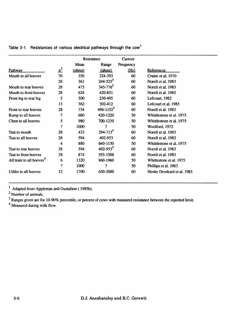
Table 3-1. Resistances of various electrical pathways through the cow^
Resistance Current Mean Range Frequency
Pathway n^ 70
iohms) 350
(çhmç) 324-393
(Hz) 60
References Mouth to all hooves Craine et al. 1970
28 361 244-525^ 60 NoreUetal. 1983 Mouth to rear hooves 28 475 345-776^ 60 NorcUetal. 1983 Mouth to front hooves 28 624 420-851 60 NoreUetal. 1983 Front leg to rear leg 5 300 250405 60 Lefcourt. 1982
13 362 302-412 60 Lefcourt et al. 1985 Front to rear hooves 28 734 496-1152' 60 NoreUetal. 1983 Rump to all hooves 7 680 420-1220 50 Whittlestone et al. 1975 Chest to all hooves 5 980 700-1230 50 Whittlestone et al. 1975
? 1000 ? 50 Woolford, 1972 Teat to mouth 28 433 294-713^ 60 NoreUetal. 1983 Teat to all hooves 28 594 402-953 60 NoreUetal. 1983
4 880 640-1150 50 Whittlestone et al. 1975 Teat to rear hooves 28 594 402-953^ 60 NweU et al. 1983 Teat to front hooves 28 874 593-1508 60 NoreUetal. 1983 All teats to all hooves^ 6 1320 860-1960 50 Whittestoneetal. 1975
? 1000 7 50 PhiUipsetal. 1963 Udder to all hooves 12 1700 650-3000 60 Henke Drenkard et al. 1985
Adapted from Appleman and Gustafson ( 1985b). ' Number of animals. ' Ranges given are for 10-90% percentile, or percent of cows with measured resistance between the reported limit ^ Measured during milk flow.
3-6 D.J. Aneshansley and R.C. Gorewit

mixed ration (TMR) typically eat about 12 meals per day, each lasting over 20 minutes; thus they spend 4.2 hours per day consuming feed. When hay and silage are offered, cows spend an average of 6.4 hours per day consuming feed. In most herd operations, competition for feed doesn't limit productivity. When cattle are fed adequately, dominant cattle may eat first and faster, but sub- ordinates will obtain their fill during times of low competition. Individual feed intakes of group-fed cattle appear to be more dependent on physiologi- cal need than social advantage.
Rumination is the act of regurgitating, remasticat- ing, and reswallowing previously ingested feed. Rumination time varies from 4 to 9 hours, with large variations both within and among animals. Rumination time is reduced when cows are fed ground hay or concentrates instead of long hay.
Cattle drink by dipping their muzzle into the water and sucking the fluid into the mouth. The tongue plays only a passive role in drinking. Cows may tend to splash or "play" with the water when drinking. Drinking fi^equency tends to increase when cattle are dependent on supplementary feeds and when housed. Water intake is a func- tion of dry matter ingestion, environmental temperature, and level of milk production. The volume of water consumed daily by a Holstein cow producing 60 pounds of milk may be 17 gal- lons when ambient temperatures average 68°F, but over 30 gallons when temperatures average 95^F.
Normal, healthy cows urinate 9 or 10 times and defecate 12 to 18 times daily. Environmental condi- tions can affect these processes. Cows will urinate less fi^equently in hot, dry environments, 3 or 4 times daily.
Adult cattle do not appear to sleep; but they typi- cally spend 9 to 12 hours per day lying down. Their head is generally held erect or turned to the side for eructation of gasses fi^om the rumen. On the other hand, calves have been observed sleeping for up to 3.2 hours daily.
Concentrating animals, by decreasing the surface area per animal, or introducing new animals into
the herd can increase aggressiveness in the herd. Keeping animals together fi^om an early age, limit- ing introductions, and keeping disturbances to a minimum are of importance in limiting aggressive- ness and social stress.
Tail-switching is sometimes used to express in- tense emotion. Restrained animals in a fearful situation tail-switch more than usual as they struggle against restraint.
Cows are often called creatures of habit. They notice any unusual change in their routine, and they often stare at or smell imfamiliar objects.
Kicking is a common behavior that can be a prob- lem. In some cases, the herdsman may choose to apply antikicking devices. Most cows kick because they are frightened, are in pain, or have been mistreated.
While most cows exhibit normal behavior patterns and respond to kindness and superior herd management, a few animals in every herd will from time to time develop behaviors which inter- fere with the regular herd routine. Stray volt- age/current problems can accentuate normal differences in behavior.
Behavioral Responses to Current The basic behavioral response of any organism to an annoying stimulus is avoidance. The response to a pleasurable stimulus is to seek it out and at- tempt reexposure to it.
Electrical current can be perceived in a variety of ways by humans. It is usually an annoying stimulus. However, it can be used therapeutically. For example, in humans, tonic electrical neural stimulation (TENS) relieves back and leg pain when it is used to saturate the specific part of the nervous system that transmits signals of pain to the brain.
Humans can avoid an objectionable voltage much more easily than cows cem. Humans can walk away from or remember not to come in contact with a voltage source. The dairy cow, however, lives in a restricted environment. Under some con- ditions, cows, like humans, may avoid the voltage
Physiological Effects 3-7

by moving their body or appendages away from the source or simply tolerate it if it is not too bothersome. However, because of management pro- cedures, cows may not be able to avoid voltage sources despite their desire to do so.
Behavioral changes are manifestations of physiological reactions occurring within the or- ganism. In cows, the extent of the behavioral change resulting from exposure to stray volt- age/current can range from subtle (leg lifting or twitching) to dramatic (muscle spasms, seizures) and is related to the intensity of the current. We must understand that what appears to be bother- some to humans may not be a problem for cows. Care should be taken not to assume that cows per- ceive their environment the same way we perceive ours.
As discussed throughout this document, the rela- tion between voltage and current is determined by the familiar Ohm's law: E = IxZ, where E is the voltage potential (volts), I is the current flow (amperes), and Z is the impedance of the total cir- cuit in ohms. Impedance often simplifies to pure resistance, R. However, R is more generally the real part of the complex impedance of the total cir- cuit at 50/60 Hz and is expressed in ohms.
The effect of a specific voltage on a cow is in- fluenced by many factors, which together deter- mine the distribution of current flow through the cow's body, namely, 1) voltage that is measurable between two points of contact, 2) source im- pedance, 3) the impedances of the electrical path- ways between the coVs contact points and source voltage, 4) the contact impedances at the two points where the cow makes contact with the electrical conductors, 5) resistance of the cow's body pathway, and 6) the sensitivity of the cow
Because these many factors cannot be determined in the field, scientists have sampled groups of cows and determined the currents necessary to elicit a response from each cow. The data obtained provide a basis upon which to estimate the statisti- cal distribution of response-eliciting currents for all cows. Likewise, groups of cows can be sampled, and the resistance of a specified path- way within each cow can be measured. These
data provide a basis upon which to estimate the statistical distribution of resistances for the specified pathway for all cows. In fact, distribu- tions of all the variables that influence the response of animals can be estimated and in most cases have been. With these estimates, it would be possible to select a sensitive cow (most sensi- tive in 100 animals), a low resistance cow (lowest in 100 animals for the lowest resistance pathway), and lowest circuit impedance (lowest in 100 condi- tions, where circuit impedance includes items 2-4 above). By multiplying these factors together, an estimate can be made of the lowest voltage that will cause 1 animal in a million animals to respond.
Over the years, many experiments have been per- formed to examine the effects of currents on the behavior and physiology of dairy cattle. It is often diflRcult to separate behavioral changes from physiological responses. Therefore, some of the re- search trials examined the effects of currents on physiology and behavior. In the paragraphs that follow, a summary will be given of those ex- perimental trials that focused on the behavioral and physiological effects of stray voltage on cows.
Behavioral Research New Zealand: Whittlestone et al. (1975) showed that cows would break their trained behavior of pushing a metal plate to receive food when this ac- tivity was coupled with the application of 2.5 mA of current over a four-teat-to-all-hooves pathway.
University of Minnesota: Norell et al. (1983) taught cows to press a plate to receive grain rewards. Then they administered a current of up to 6 mA over the front-to-rear-hooves pathway whenever the plate was pushed. Applying the cur- rent did not affect the learned plate-pressing be- havior. In a similar test, but with the muzzle-to-all hooves pathway, plate pressing was delayed by current varying from 1 to 4.5 mA on the first test day and from 3 to 4.5 mA on sub- sequent days. In a second experiment, cows were trained to raise their front hoof to avoid continua- tion of a front-to-rear-hooves exposure to current. Ninety-seven percent of the animals showed the learned escape response at currents above 2 mA. To avoid shock over the mouth-to-all-hooves path-
3-8 D.J. Aneshansley and R.C. Grorewit

way, mouth opening was the specific response. Fif- teen percent of the cows responded to 1.0 mA and 90 percent to 5.0 mA. In other experiments, cows subjected to a 4-mA current required twice as much time to cross a grid from the preparation stall to a milking stall compared to control animals.
USD A and Cornell University: Lefcourt (1982) and Lefcourt et al. (1986) examined a front-leg-to- rear-leg pathway. Most of the cows in his experi- ments exhibited mild responses such as flinching or vocalization at 3.0 mA of current. The most sen- sitive cows responded to 1.0 mA of current. Henke Drenkard et al. (1985) at Cornell University used an udder-to-all-hooves pathway on four lactating cows. Their results suggested that some cows were sensitive to 2 mA, but most responded to 4 mA.
University of Minnesota: Gustafson et al. (1985b) foimd that for the front-to-rear-hooves and mouth- to-all-hooves pathways, the avoidance responses (front leg raising and mouth opening, respectively) were obtained over a range of ac and dc currents, 0 to 5 mA ac and 0 to 6 mA dc. The response rate for the front-to-rear-hooves pathway was statisti- cally significant above 2 mA ac, and above 1 mA dc. The response rate for the mouth-to-all-hooves pathwaywas significantly greater above 2 mA ac, and above 4 mA dc. Response rates for the body-to- all-hooves pathway, with currents from 0 to 7.5 mA ac and from 0 to 9 mA dc were inconclusive. No reliable response pattern was obtained for the body pathway.
Combined Physiological and Behavioral Re- search Hormones are chemicals that are produced in specific organs, and they enter the blood and react with various tissues in the body. Basically, there are two types of hormones. Those produced in ductless glands are called endocrine hormones. Hormones that are manufactured in glands with ducts are called exocrine hormones. Hormones in- fluence many biological functions of the body, in- cluding growth, development, and metabolism.
Certain endocrine hormones are very important for development of the udder and its day-to-day function. These hormones are insulin, growth hor- mone, adrenal glucocorticoids, prolactin, thyroid hormones, ovarian hormones, oxytocin, and catecholamines such as epinephrine (adrenaline). Ovarian hormones, insulin, prolactin, growth hor- mone, glucocorticoids, and prolactin are also in- volved in mammary development. Oxytocin and catecholamines are involved in milk ejection, or let- down. Cortisol, prolactin, and oxytocin are released during normal milking of dairy cows. During stress, catecholamines, cortisol, and prolac- tin are all released. Catecholamines can block the effects of ox3Íx)cin and thereby decrease milk yields. Incomplete milk removal, in turn, can in- crease the chance that the cows will get mastitis if their udders are exposed to microorganisms.
As mentioned in chapter 1, stray voltage has been associated with problems in milk let-down and an overall decrease in milk production. If stray vol- tages are a stress to lactating dairy cows, one would assume that exposure to these voltages iinder controlled experimental situations would result in the elevation of stress hormone levels in blood. Workers at USDA and Cornell University have carried out several experiments which were specifically designed to measure the effects of various currents and voltages on the levels of hor- mones naturally released during stress in the dairy cow and on their relationship to blood flow, milk flow, milk yield, milk composition, and release of oxytocin, prolactin, cortisol, and catecholamines.
Cornell University : Holstein cows were exposed during milkings to electrical current to assess its effects on behavior, health, milking performance, and endocrine responses (Henke Drenkard et al. 1985). Treatments consisted of 60-Hz square-wave current of 5 seconds' duration applied every 30 seconds from udder to hooves. Three treatments (0, 4, and 8 mA; 0, 1.6, and 3.2 V) were appHed over three consecutive 1-week periods. A cow received the same current treatment during 14 consecutive milkings, beginning with the evening
^Studies at Cornell prior to 1986 used alternating, constant current sources for stimulation. Subsequently, sinusoidal currents were used. Responses to both types of currents were similar.
Physiological Effects 3-9

milking and ending with the morning milking. Treatments began 5 minutes before milking and continued until milking imit removal. Milk ac- cumulation curves provided information about milk yields, milking times (durations), peak milk flow rates, and times of peak milk flow. Residual milk yields also were measured. Milk was analyzed for protein, fat, and somatic cells. Blood samples from 60 minutes before to 60 minutes after treatment were collected, and oxytocin, prolactin, and cortisol concentrations were measured.
Behavioral responses to current decreased afl^r in- itiation of milking and with repeated trials. Chan- ges in milk production, milking performance, and milk composition were not significant. Changes in milking-related cortisol responses during 8-mA cur- rent stimulation were significant. Oxytocin release was delayed during 8-mA treatments. Current treatments did not affect prolactin concentrations or animal health.
The Cornell group also examined the effects of three intensities of current (4, 6, and 8 mA; 1.6, 2.4, and 3.2 V) on milk production, milk composi- tion, health, and levels of hormones normally released at milking in cows. No significant chan- ges in health, hormone levels, or milk production or composition were seen after cows were exposed to electrical current. Once more, cows quickly be- came acclimated treatments.
In order to randomize the exposure of cows to electrical current and eliminate their ability to avoid exposure to treatments, Gorewit et al. (1984a) performed the following experiment. Holstein cows were assigned to two groups of four each. Treatments were 4 mA (3.5-3.8 V) or no cur- rent for four 96-hour periods. The current was ap- plied across electrodes penetrating the hide of the animals, one electrode on each side of the spine in the lumbar area. For 5 minutes current was given for 30-second durations between 30-second rest periods. Cows received current every 4 hours for four 24-hour intervals. No individual cow received current at the same time every day. Milk yield was reduced 0.16 kg (0.32 lb) per milking by ex- posure to a 4-mA current. This decrease was not statistically significant. Percentages of milk fat
and milk protein were not changed by current. Overall numbers of milk somatic cells were vari- able during the experiment. Feed and water con- sumption were not influenced by treatments. The greatest behavioral response to current was shown upon initial exposure. Cows became accustomed to shock within 24 hours of exposure. By the end of the fourth 96-hour period, behavioral responses to current were almost extinct. It was concluded that exposing cows to 4 mA (3.5-3.8 V) of alternating current in a semirandomized nonavoidance en- vironment for four consecutive 24-hour intervals (96 hours) does not alter milk yield, milk composi- tion, or intake of feed and water.
Grorewit and Aromando (1985) examined the ef- fects of electrical current on cardiovascular respon- ses. They foimd that normal milking causes the release of oxj^cin, which causes an increase in mammary blood flow, and that epinephrine can reduce this normal milking-induced change in blood flow. Cows were tested to see whether they would show a change in heart rate and mammary blood flow upon exposure to current. If electrical shock is stressful, no increase in blood flow during milking would be expected because of epinephrine release. An experiment to determine the effects of 4 mA (3-6 V) of square-wave ac exposure on mam- mary-gland blood-flow rate, heart rate, and blood pressure of cows at rest and throughout milking was performed. Current was administered to cows through electrodes located near the spine begin- ning 10 seconds prior to udder massage and throughout milking. Without current, a single rise in mammary-blood-flow rate occurred during milk- ings, and mammary blood flow increased within 40 seconds of milking — heart rate and blood pres- sure did not change significantly. Cows subjected to current showed abrupt increases in mammary blood flow rate, heart rate, and blood pressure im- mediately upon current application prior to milk- ing. A second rise in mammary blood flow occurred during milking within 42 seconds of milk- ing machine attachment. Milk yield was not in- fluenced by current. The experimental data showed that 4 mA (3.6 V) of alternating current applied prior to and during milking does not in- fluence normal physiological changes in mammary- gland blood flow during milking.
3-10 D.J. Aneshansley and R.C. Gorewit
USDA'Agricultural Research Service (ARS): As mentioned previously, catecholamine release has been considered to be a causative factor for decreased milk production and lactational inhibi- tion in cows exposed to stress. However, Lefcourt et al. (1982) found no change in plasma concentra- tions of epinephrine (adrenalin) and norepinephrine in cows subjected to electrical cur- rent between milkings. Six cows were subjected to 5-mA-ac treatments starting 10 minutes prior to milking and lasting for 20 minutes. Current was supplied either continuously or intermittently for 5 of every 30 seconds. Voltage was applied to abraded skin on front and rear legs via electrocar- diogram electrodes and ranged from 1.1 to 2 V. During intermittent voltage treatment, milking time decreased by 50 seconds and milk yield decreased by 10 percent. Analysis of blood samples revealed no change in norepinephrine, epinephrine, or oxytocin concentrations. Neither the USDA-ARS group nor any other research team has been able to reproduce this drop in milk production since this study was published.
In a subsequent study (Lefcourt et al. 1985), seven cows were subjected to 3.6-mA-ac and six cows to 6.0-mA-ac treatments for 7 days. Current was applied intermittently as described above at both morning and evening milkings. Comparsion of data obtained during the 7-day treatment periods with data obtained during the 5-day pretreatment and 5-day posttreatment period; showed that milk yield, milking time, and Wiscon- sin Mastitis Test scores were not affected by either treatment. It was concluded that "milk 3deld can be maintained, at least in the short term, in cows subjected to electrical shock due to power-line problems if dairy producers take excep- tional care to accommodate behavioral responses." It should be noted that the original experimental design called for a 12-mA treatment. This treat- ment was dropped from the experimental protocol after the first set of cows were exposed to 12 mA because of the severe behavioral responses elicited. These responses, if even slightly exag- gerated, might have resulted in an animal catch- ing a leg between crossbars normally used to contruct stalls and possibly being injured.
In another study, cows were subjected for 10 seconds to current treatments of 0, 2.5, 5.0, 7.5., 10.0, and then 12.5 mA (Lefcourt et al. 1986). Cur- rent was applied between milkings as described above. Norepinephrine concentrations remained un- affected. Epinephrine concentrations increased for two cows during the 10-mA (5-V) treatments. There were transient increases in heart rate imme- diately after the 10- and 12.5-mA treatments. Milk production was not reduced by any of the treatments in this study.
Production, Reproduction, and Health
Water Bowl Research Milk is 87 percent water. A reduction in water in- take reduces milk production. Feed consumption is also reduced when water intake decreases, thus decreasing milk yields even further.
Washington State University: Craine et al. (1970) found that cows choose to drink less often from water troughs carrying an applied voltage. Water troughs at 3 and 6 V relative to earth were visited 20 and 68 percent less often, respectively, than troughs without voltage. Also, heifers did not drink for more than 8 hours from a water trough with 8 V relative to earth, and then they only drank from the trough reluctantly.
Cornell University: Since 1985, Cornell re- searchers have emphasized examining the effects of voltage applied between the water source and hooves of cows. A number of long-term and short- term studies have been conducted. Cows were ex- posed to constant voltages (0.5 to 4 V for 21 days and 3 to 6 V for 2 days) (Aneshansley et al. 1987, Gorewit et al. 1987, Gorewit et al. 1988, Gorewit et al. 1989) and discontinuous voltages (6 V, 12 hours of the day for 7 days; 8-V pulses every 20 seconds, 12 hours of the day for 7 days) (Aneshansley et al. 1988b).
The first water bowl experiment involved 21-day exposures to 0, 0.5, 1.0, 2.0, and 4.0 V. These ex- posures were preceded and followed by 2-week pretreatment and 2-week posttreatment periods. Water and feed intake, milk yield and quality, and aspects of udder and animal health were monitored throughout the 7-week trial. The path
Physiological Effects 3-11
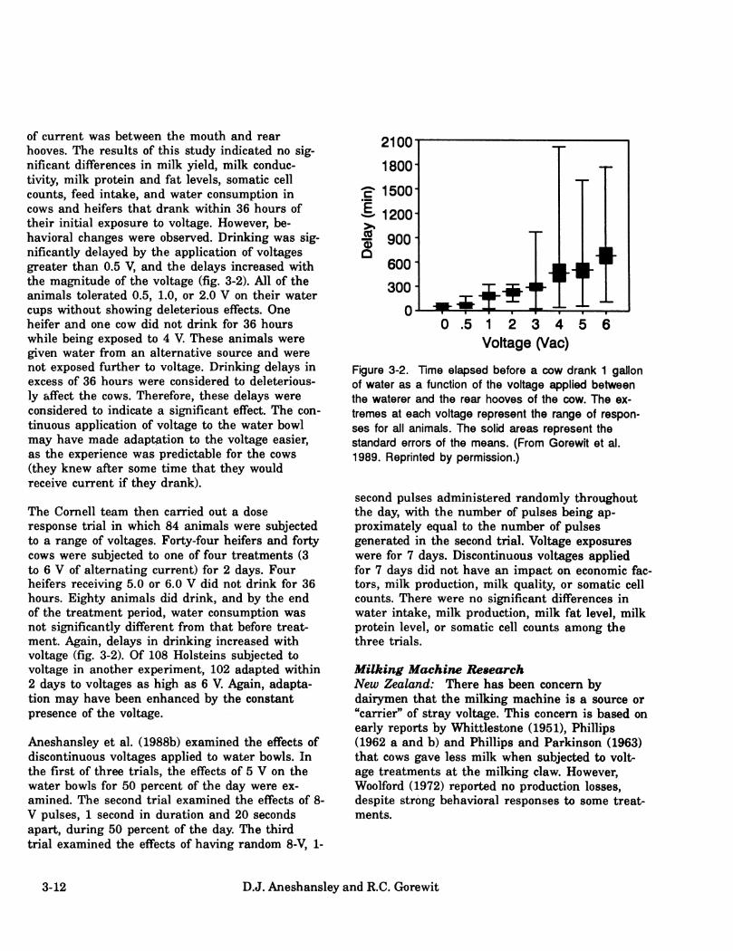
of current was between the mouth and rear hooves. The results of this study indicated no sig- nificant differences in milk )deld, milk conduc- tivity, milk protein and fat levels, somatic cell counts, feed intake, and water consumption in cows and heifers that drank within 36 hours of their initial exposure to voltage. However, be- havioral changes were observed. Drinking was sig- nificantly delayed by the application of voltages greater than 0.5 V, and the delays increased with the magnitude of the voltage (fig. 3-2). All of the animals tolerated 0.5, 1.0, or 2.0 V on their water cups without showing deleterious effects. One heifer and one cow did not drink for 36 hours while being exposed to 4 V. These animals were given water fi:*om an alternative source and were not exposed further to voltage. Drinking delays in excess of 36 hours were considered to deleterious- ly affect the cows. Therefore, these delays were considered to indicate a significant effect. The con- tinuous application of voltage to the water bowl may have made adaptation to the voltage easier, as the experience was predictable for the cows (they knew after some time that they would receive current if they drank).
The Cornell team then carried out a dose response trial in which 84 animals were subjected to a range of voltages. Forty-four heifers and forty cows were subjected to one of four treatments (3 to 6 V of alternating current) for 2 days. Four heifers receiving 5.0 or 6.0 V did not drink for 36 hours. Eighty animals did drink, and by the end of the treatment period, water consumption was not significantly different from that before treat- ment. Again, delays in drinking increased with voltage (fig. 3-2). Of 108 Holsteins subjected to voltage in another experiment, 102 adapted within 2 days to voltages as high as 6 V. Again, adapta- tion may have been enhanced by the constant presence of the voltage.
Aneshansley et al. (1988b) examined the effects of discontinuous voltages applied to water bowls. In the first of three trials, the effects of 5 V on the water bowls for 50 percent of the day were ex- amined. The second trial examined the effects of 8- V pulses, 1 second in duration and 20 seconds apart, during 50 percent of the day. The third trial examined the effects of having random 8-V, 1-
2100-
1800- T ;£• 1500-
¿ 1200-
t 900- Q
600-
300-
0- ,^f*"tTi 0 .5 1 2 3 4 5 6
Voltage (Vac)
Figure 3-2. Time elapsed before a cow drank 1 gallon of water as a function of the voltage applied between the waterer and the rear hooves of the cow. The ex- tremes at each voltage represent the range of respon- ses for all animals. The solid areas represent the standard errors of the means. (From Gorewit et al. 1989. Reprinted by permission.)
second pulses administered randomly throughout the day, with the number of pulses being ap- proximately equal to the number of pulses generated in the second trial. Voltage exposures were for 7 days. Discontinuous voltages applied for 7 days did not have an impact on economic fac- tors, milk production, milk quality, or somatic cell counts. There were no significant differences in water intake, milk production, milk fat level, milk protein level, or somatic cell counts among the three trials.
Milking Machine Research New Zealand: There has been concern by dairymen that the milking machine is a source or "carrier" of stray voltage. This concern is based on early reports by Whittlestone (1951), Phillips (1962 a and b) and Phillips and Parkinson (1963) that cows gave less milk when subjected to volt- age treatments at the milking claw. However, Woolford (1972) reported no production losses, despite strong behavioral responses to some treat- ments.
3-12 D.J. Aneshansley and R.C. Gorewit

Cornell University: To determine the effects of ac voltages applied through the milking machine, re- searchers at Cornell exposed eight cows to 0, 4, 8, and 16 V and eight heifers to 0, 2, 4, and 8 V ap- plied through electrodes at the distal end of the milking machine inflations (Aneshansley et al. 1988b). Each cow received all treatments in a Latin square design on four consecutive milkings over 2 days. Behavioral response, milk production, residual milk, machine-on time, milk composition, and current (temporal pattern during milking and maximum value) were recorded. Only behavioral response was significantly affected by differences in the voltage. Behavioral responses (kicking machine off and "dancing^ ) were observed with 8 V for the heifers and 16 V for the cows and only when these voltages produced currents in excess of 6 mA for the heifers and 8 mA for the cows. Current during milking increased with milk flow and with increased numbers of somatic cells.
In another set of experiments, 3 mA of current was applied through the milk to 8 heifers and 5 mA to 8 cows for 14 consecutive milkings. Milk production was not significantly affected by cur- rent exposure.
University of Minnesota: Gustaf son et al. (1983) showed that the minimum resistances from high- and low-line milking systems are 79.9 and 30.3 kohms, respectively. They also showed that the minimum resistance from the metal claw through the cow to the floor is 3 kohms. Between a milk- ing system and the concrete floor, the voltages that would generate perceived currents (1 mA) through the cow would have to be about 50 Vac and 25 Vac for high and low lines, respectively. Thus, it would be very difficult for cows to receive perceptible currents from these stray voltage sour- ces when bucket milked.
Long-Term and Full-Lactation Research Two research groups have studied the long-term ef- fects of voltage exposure on behavior, milk produc- tion, reproduction, and health of cows.
New Liskeard College, Ontario, Canada: Two tri- als were performed to examine the effects of volt- age on milk production, incidence of mastitis, feed and water consumption, fertility, and behavior.
Each trial was run according to a switchback design involving four consecutive 4-week periods (112 days).
Cows were randomly placed into one of six groups between 10 and 14 days postpartum. Each cow was exposed to two 4-week periods of voltage and two 4-week periods without voltage. Voltage was applied between the floor and the water bowls, stanchions, and head rails, the last three types of fixtures being electrically connected. During the voltage periods, cows received the test voltage (1.0 V, trial 1 and 2.5 V, trial 2) from 5 a.m. to 8 a.m. and 5 p.m. to 8 p.m. During the remaining time they received a base level voltage which was 30 percent of test voltage (0.3 and 0.75 volt for trials 1 and 2, respectively). The variation in voltage was used to represent the changes in peak load on most dairy farms.
Parameters measured were voltage level; daily milk production; milking speed; milk composition; water consumption; feed consumption; estrus be- havior; behavior, including number of times each animal urinated, defecated, and drank and the amount of time the animal spent lying or stand- ing; and environmental temperature and relative humidity.
In subsequent trials, cows were subjected to up to 5 V. Preliminary analysis of the results showed no significant changes in any of the parameters measured as a function of voltage.
Cornell University: Researchers exposed 40 cows (2d-5th lactation) in groups of 10 to 0, 1, 2, or 4 V for a full lactation. The voltage for each group of 10 was applied between the water bowl and front hooves. Milk production, water and feed intake, reproduction, and animal health were not affected at any treatment level. In addition, analysis of blood samples showed no change in the immune system of the animals. Pregnancies, days-open, abortions, and other reproductive data were nor- mal for all treatments compared to nonexperimen- tal cows in the imiversity dairy herd.
Physiological Effects 3-13
Observations From Dairy Farms
The symptoms shown by animals subjected to stray voltages vary, depending on the pathway through the animals and the magnitude of the voltage. There are three general classifications of symptoms, and they are related to 1) behavior modification, 2) milking characteristics, and 3) production performance. It must be remembered, however, that many factors other than stray volt- age can cause behavior, health, or production problems. These factors include management and cow handling methods, environmental conditions, nutritional disorders, mastitis control methods, sanitation, and disease. The following are the most common symptoms reported in field observa- tions.
Ssmiptoms Attributed to Stray Voltage
Behavior Excessive or Unusual Nervousness in Milking Par- lor or Stall Barn at Milking: Unusual nervous- ness at milking is often characterized by cows dancing or stepping around while in the stall. If this behavior is caused by stray voltage, it is usually due to a voltage between the stall pipes (which the cow touches) and the concrete floor (on which the cow is standing). There must be contact between the voltage source and the cow. However, dairy farmers are reminded that cows may be- come nervous for reasons other than stray volt- age, such as malfimctioning milking equipment (too high vacuum or inappropriate pulsation ratios) or operator abuse. Even a change in milk- ing routine may result in cows temporarily appear- ing nervous.
Reluctance 7b Enter and/or Eagerness 7b Flee Milking Parlor: Cows subjected to stray voltages in the parlor stalls soon become reluctant to enter the parlor. In extreme cases, nearly all cows have to be driven into the parlor, and they may tend to stampede out upon release. But again, reluctance to enter the parlor is not specific to stray volt- age/current problems because cows may be trained
to expect the parlor operator to chase them into the milking stalls.
Increased Frequency of Defecation and/or Urina- tion in Milking Parlor: It is well documented that nervous cattle will excrete body wastes more frequently. This phenomenon may be due to con- tact with stray voltage or to other causes, includ- ing operator abuse, presence of strangers, and change to green feed from dry roughages.
Reluctance To Consume Water or Feed: Any class of livestock that is subjected to stray voltage may exhibit the sjrmptom of reduced intake of water and/or feed. Documented cases include dairy and beef cattle, swine, and poultry. Reduced intake may be manifested generally throughout the farmstead or only at a specific waterer or feeding location. Grenerally speaking, higher voltages are required to limit water or feed consumption than to alter the other behavioral characteristics dis- cussed previously. A rather specific symptom in- dicative of a probable stray voltage/current problem is the uncharacteristic lapping of water during animals' attempts to meet their demand for water. Farmers must recognize, too, that there are other causes for these behaviors, especially boredom by cattle confined to stalls, change in water quality, the feeding of spoiled or un- palatable feeds, and sickness.
Milking Characteristics Poor milk let-down, incomplete milk-out fleaving abnormal amounts of residual milk in one or more quarters), and increased milking time are common symptoms noted by dairy farmers having stray voltage/current problems. The physiological mechanisms preventing satisfactory milk-out are not fully xmderstood. Researchers haven't been suc- cessful in identifying any significant hormonal changes. However, researchers have demonstrated that the milking-machine-hose/udder pathway, even under high flow rates, is not a likely path- way for electrical currents to the cow.
Poor Milk Let-Down and Incomplete or Uneven Milk-Out: The number of cows affected by and the severity of milk let-down problems appear to be dependent on the level of stray voltage present. When it is high enough to cause the cows to move
3-14 D.J. Aneshansley and R.C. Grorewit
or step about during the milking process, it is dif- ficult to keep the milking unit properly aligned and adjusted to provide an even weight distribu- tion necessary to promote fast, effective milk-out. On the other hand, a damaged teat canal may result in one quarter being consistently slow to milk-out. Milking machine dysfimction can also result in uneven or incomplete milk-out.
Increased Milking Time: If the stray voltage/cur- rent problem is severe enough to affect cows' be- havior, such as kicking off the machine, milk-out may be influenced. This problem can result in ad- ditional time needed for milking.
Production Performance: Although stray voltage has not been shown to have a direct physiological effect on cows, severe behavioral responses will complicate management practices. As a result, labor efficiency and profitability may be lowered.
Increased Somatic Cell Count and Incidence of Clinical Mastitis: Mastitis, whether clinical or subclinical (indicated by high somatic cell coxmts), is the result of an infection of the mammary gland. Such infections aren't directly caused by stray voltages. However, if cows' behavior is modified, and if the milking routine is altered be- cause of the change in cows' behavior, what may result is a less satisfactory milking performance, increased somatic cell counts, and increased in- cidence of clinical mastitis.
Lowered Milk Production: If cows drink less water, consume less food, or develop mastitis, they are likely to produce less milk. Whether or not milk production will be adversely affected by stray voltage depends on the extent to which the cows' behavior is altered and how management compen- sates. On the other hand, improvement in milk production is not always apparent after a stray voltage/current problem has been corrected (see "Farm Surveys," below).
Attempts have been made to associate the problems of unthrifty and unhealthly animals, poor reproduction, and weak calves with stray volt- age. The failure of controlled research to find a direct physiological effect in animals subjected to stray voltages and the absence of documented
case studies demonstrating a marked improve- ment in these traits upon correction of an existing problem lead to the conclusion that there is no direct and causal relationship.
In summary, recall that many nonelectrical condi- tions can cause symptoms similar to those result- ing from the exposure of animals to stray voltage. A careful analysis of all possible causes of unusual animal behavior and/or poor animal performance is necessary if proper corrective procedures are to be found.
Farm Surveys
The national and worldwide nature of stray volt- age/current problems has been recognized. Australian researchers implied in 1948 (Churchwood 1948) that current resulting from electrical equipment in the milking area may have affected cows negatively. New Zealand researchers published a similar statement in 1962 (Phillips 1962 a and b). Investigators from the Washington State University first reported stray voltages in the United States in 1969 (Graine et al. 1969a and 1970). Canadians reported incidences of stray voltage problems in 1975 (Feistman and White 1975).
Starting in 1980, problems from stray voltages began to surface throughout much of the United States and Canada. Some researchers estimated that 20 percent of all parlor operations were probably affected. Results from a survey of 131 Ontario dairy farms showed that 80 percent of the farms had voltages on the electrical neutral suffi- ciently high to be a possible problem. Based on the guidelines recommended in this handbook (see chapter 7), from 29 to 36 percent of those farms had a voltage differential between cow contact sur- faces sufficient to be of concern. One problem with these statistics is that they are not based on uniform criteria and are therefore somewhat mis- leading.
Recently Appleman et al. (1987 a and b) surveyed a number of farms in west-central Minnesota. Through the cooperation of four rural electric cooperatives and one investor-owned utility, 394 of the farms were identified as having primary and
Physiological Effects 3-15
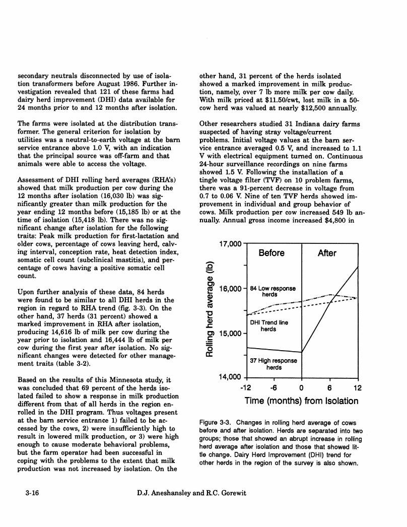
secondary neutrals disconnected by use of isola- tion transformers before August 1986. Further in- vestigation revealed that 121 of these farms had dairy herd improvement (DHI) data available for 24 months prior to and 12 months after isolation.
The farms were isolated at the distribution trans- former. The general criterion for isolation by utilities was a neutral-to-earth voltage at the bam service entrance above 1.0 V, with an indication that the principal source was off-farm and that animals were able to access the voltage.
Assessment of DHI rolling herd averages (RHA's) showed that milk production per cow during the 12 months after isolation (16,030 lb) was sig- nificantly greater than milk production for the year ending 12 months before (15,185 lb) or at the time of isolation (15,418 lb). There was no sig- nificant change after isolation for the following traits: Peak milk production for first-lactation and older cows, percentage of cows leaving herd, calv- ing interval, conception rate, heat detection index, somatic cell coiuit (subclinical mastitis), and per- centage of cows having a positive somatic cell count.
Upon further analysis of these data, 84 herds were found to be similar to all DHI herds in the region in regard to RHA trend (fig. 3-3). On the other hand, 37 herds (31 percent) showed a marked improvement in RHA after isolation, producing 14,616 lb of milk per cow during the year prior to isolation and 16,444 lb of milk per cow during the first year after isolation. No sig- nificant changes were detected for other manage- ment traits (table 3-2).
Based on the results of this Minnesota study, it was concluded that 69 percent of the herds iso- lated failed to show a response in milk production different from that of all herds in the region en- rolled in the DHI program. Thus yoltages present at the bam service entrance 1) failed to be ac- cessed by the cows, 2) were insufficiently high to result in lowered milk production, or 3) were high enough to cause moderate behavioral problems, but the farm operator had been successful in coping with the problems to the extent that milk production was not increased by isolation. On the
other hand, 31 percent of the herds isolated showed a marked improvement in milk produc- tion, namely, over 7 lb more milk per cow daily. With milk priced at $11.50/cwt, lost milk in a 50- cow herd was valued at nearly $12,500 annually.
Other researchers studied 31 Indiana dairy farms suspected of having stray voltage/current problems. Initial voltage values at the bam ser- vice entrance averaged 0.5 V, and increased to 1.1 V with electrical equipment turned on. Continuous 24-hour surveillance recordings on nine farms showed 1.5 V. Following the installation of a tingle voltage filter (TVF) on 10 problem farms, there was a 91-percent decrease in voltage from 0.7 to 0.06 V. Nine of ten TVF herds showed im- provement in individual and group behavior of cows. Milk production per cow increased 549 lb an- nually. Annual gross income increased $4,800 in
17,000
0)
0) n O)
JO
o er
16,000- 84 Low response herds
15,000-
14,000
Before
DHI Trend line herds
37 High response herds
After
6 -12 -6 0 6 12
Time (months) from Isolation
Figure 3-3. Changes in rolling herd average of cows before and after isolation. Herds are separated into two groups; those that showed an abrupt increase in rolling herd average after isolation and those that showed lit- tle change. Dairy Herd Improvement (DHI) trend for other herds in the region of the survey is also shown.
3-16 D.J. Aneshansley and R.C. Gorewit

Table 3-2. Change in values of management parameters for the upper 31 percent of herds ranked according to percentage increase in rolling-herd-average milk production after isolation
For the 1 vear ending: 1 year Time 1 year before of after
Parameter isolation isolation isolation Production traits (lb)
Ï
Annual milk/cow 14,687^ 14,616* 16,444** Peak milk, Ist-lactation cows 53.0 55.7 56.7 Peak milk, older cows 70.1 71.9 75.0
Herd size No. cows 50.0 51.3 53.5 Cows leaving herd, % 35.6 36.4 37.6
Mastitis Somatic cell coimt 408,300 300,600 340,600 Cows positive, % 26.2 26.8 24.6
Reproduction Calving interval, months 13.1 13.1 13.1 Heat detection index, % 48.0 47.0 46.4 Conception rate, % 58.9 59.9 58.2
*'*^Means within a row differ (P<0.05) when superscripts differ.
Physiological Effects 3-17

the 10 TVF herds, which averaged 70 cows per herd.
Problems with Interpreting Survey Data
The most common form of survey involves a series of questions designed to detect or confirm relation- ships among known or suspected factors. The prin- cipal problem with surveys of this type is confirming that a detected relationship is causal, i.e., that one factor caused the second to occur as opposed to both factors being unrelated except by chance or by some shared input from a third agent. The critical problem for establishing causality is to determine the mechanism by which the factors are related. For example, if survey data indicates that an outbreak of food poisoning was caused by eating the daily special at "Ernie's" Friday night, the mechanism can be shown to be contaminated food if, and only if, it can be scien- tifically established that the food was con- taminated and that the contaminated food was capable of producing symptoms of food poisoning.
A more complex type of survey might examine the effect of a treatment on a number of factors. For example, does lowering the neutral-to-earth volt- age at the service entrance from 2.0 to 4.0 V to less than 0.5 V result in increased milk produc- tion? Besides establishing a mechanism as dis- cussed above, there are two additional critical problems with establishing causality for this tj^e of survey. First, the treatment must be specific. For the example, this would mean that nothing on the farm and no farm operations are altered ex- cept for the reduction in voltage at the service entrance. Second, a control group is needed to demonstrate that changes are due to the treat- ment rather than from random or unknown fac- tors. For the example, this means that milk production would have to be monitored on two sets of identical farms, one set where the voltage is reduced and one set where no mitigation is per- formed.
The perfect survey situation does not exist and it is obvious that some compromise of the critical problems outlined above is inevitable. Still survey data is very valuable for suggesting new lines of inquiry. In terms of stray voltage/current
problems, survey data is less useful. The inability to scientifically establish a direct effect of stray voltage/current on milk production violates the first critical problem with surveys, i.e. estab- lishing the mechanism of a supposed causal relationship. The second critical problem requires that the treatment be specific. Farmers are con- stantly changing farm operations and when problems are known to exist on a farm, the farmer is even more likely to make changes. Under these conditions, it is impossible to at- tribute any increase in production to a single change. In figure 3-3, milk production following stray voltage mitigation increased only on farms with initially lower than average production. This suggests that these farms were not optimally managed and that the adoption of improved management techniques, which often accompanies intervention of coimty agents or others, was large- ly responsible for the increase in production. The third critical problem is the adequacy of the con- trol group. For figure 3-3, as with most stray volt- age surveys, no comparison was made to farms where elevated voltages were previously identified but not mitigated.
Factors Affecting Response
Responses of animals to electric current will vary from animal to animal. Differences in responses can be related to each animal's genetic heritage, past exposure to current and other noxious stimuli, and environment at the time of the ex- posure. The progression of responses as current levels increase — awareness, irritation, pain, and finally death — is similar for all cows. The prin- cipal challenge is to determine the maximum cur- rent level which results in awareness but not irritation for most cows under normal manage- ment conditions. Therefore, the following discus- sions will focus on effects of low-intensity currents, Le., currents that cause awareness or irritation; thus, some of the statements made below are not applicable for high-intensity currents.
3-18 D.J. Aneshansley and R.C. Gorewit

Perception and Interpretation of Stimuli
Cows feel the passage of small electrical currents through their bodies, and all cows have similar capabilities to feel these currents. Therefore, dif- ferences in how cows respond to current depend not on their ability to feel the current but, in- stead, on their perception and interpretation of it. One factor which influences how noxious stimuli like exposure to electrical current are perceived is the genetic heritage of the animal. In humans, responses to noxious stimuli vary from individual to individual, and genetic makeup and/or psychological profile can be correlated to type and degree of response. In cows, it has been shown that the level of current necessary to elicit be- havioral changes varies from cow to cow. Of cows tested, a small percentage, less than 3 percent, showed behavioral changes at relatively low cur- rent levels. It is impossible to determine to what degree the sensitivity of these cows was due to genetic heritage or to past history. However, be- cause the currents were administered under ex- perimentally controlled conditions, differences in responses were not due to changes in the cir- cumstances imder which the currents were ad- ministered.
Prior experiences will most definitely influence how a cow responds to current. For example, the response to any novel stimulus will be exag- gerated, and the initial response of cows to a very low intensity electric current is often exaggerated and sometimes even appears theatrical. If the cur- rent is sustained, the cows quickly adapt; and after a period of minutes, behavior appears nor- mal. If, instead, currents of short duration are repeated, the greatest response is at the onset of the stimulus, and after a few exposures, even the response to the onset of the exposure is gone. A cow's history will also influence how she responds to electrical currents. Previous traumatic experien- ces will tend to diminish responses to currents. Furthermore, cows have often had prior exposure to electrical currents because of the accepted use of trainers and electrified fences. Perhaps electri- cal current is perceived as a minor irritation when compared with the trauma of dehorning or calving. Sometimes the particular way in which an animal is raised can influence its perception of
the world. For example, chickens raised in small cages and then allowed to enter a large yard will initially express a preference for the confining cages. In contrast, chickens raised in a large yard will be quite distressed when placed in cages. There are probably many such environmental fac- tors which can potentially influence a cow's respon- ses to electric stimuli; however, it is difficult to identify specific factors and next to impossible to determine the relative importance of these factors in terms of their influence on responses to electri- cal stimuli.
Predictability and Controllability of Stimuli
Predictability and controllability of stimuli are im- portant concepts which help us to imderstand how cows perceive and interpret electrical stimuli. Pre- dictability involves the ability of a cow to predict when an exposure to current will occur. Control- lability has to do with whether the cow can avoid the exposure. Both predictability and control- lability are continuous functions with two ex- tremes. One extreme for predictability is for the exposure to be associated with some easily recog- nizable event, e.g., attachment of the milking machine. The other extreme is that exposures are totally random, occurring at any time or place. The extremes for controllability are absolute con- trol at essentially no cost in effort and no control regardless of energy expended.
Cost, or energy expenditure, is an important aspect of controllability. Often a noxious stimulus can be avoided if the animal is willing to expend the necessary time and energy. For example, shade might be available on a hot and sunny day if the cow is willing to leave the pasture and return to the bam.
The interactions between predictability and control- lability are actually much more important in terms of responses to current than is either factor alone. One of the most distressing combinations arises when the advent of exposure is easily pre- dictable but totally xmcontrollable (or un- avoidable). The distress is further increased if for some reason the animal believes the exposures can be avoided when in reality they cannot be avoided. Such a circumstance arose in an experi-
Physiological Effects 3-19

ment where two monkeys in adjacent cages were shocked. One monkey could avoid the shocks if he pressed a button after hearing a buzzer. The second monkey was shocked whenever the first monkey was shocked, i.e., when the first monkey didn't bother to press his button. The second monkey became quite distressed. On a dairy farm, electrical stimuli are likely to be reasonably pre- dictable.
Exposure to electrical currents depends on the ex- istence of a voltage source. This voltage source will determine where and how exposures occur. Cows will normally know in which building they will be exposed and may even be able to reliably predict when each exposure will occur. The ability to predict exposures is not a problem by itself, as prior warnings tend to reduce the impact of noxious stimuli. Only when there is an ap- pearance of controllability does predictability be- come a problem. For example, a cow might know that there is a good chance of her being exposed if she enters the milking parlor. She may decide to avoid the exposure by not entering the milking parlor. The farmer then force her into the parlor. Thus, the apparent ability of the cow to avoid the exposure has been thwarted. Forcing the cow into the parlor under these circumstances could result in significant physiological and psychological responses. These responses are much greater than the responses to the current itself. The best way to handle this particular problem is to cajole the animal into entering the parlor rather than forc- ing her to enter. This example is important for two reasons. First, it demonstrates that animal management techniques can significantly influence how cows respond to stray voltages. Second, it shows that exposure to stray voltages/currents can create secondary problems that have a greater im- pact on production than the current itself.
Another example of a possible on-farm problem is a voltage potential between the waterer and the floor. When the voltage is always present, the cow knows exactly what causes the stimulus and has absolute control over when each exposure will occur. In cases where the voltage is present at ran- dom intervals, the cow can test the waterer and decide whether or not to drink. Because the cow has control over when she will be exposed, the
psychological impact of the current is reduced. Under experimental conditions, most cows rapidly adapt to a constant presence of voltage across the waterer, and drinking patterns quickly return to normal. When the voltage is present at random in- tervals, drinking patterns also return to normal, and there is no difference in drinking patterns be- tween periods when the voltage is present and when it is not. The cows will ignore the currents and drink when they are thirsty.
Genetic Selection
Evidence from stray voltage experiments suggests that as a result of the genetic selection of animals for productivity, the ability of those animals to respond to noxious stimuli has been reduced. In dairy cows, electrical stimuli during milking and between milkings do not cause any significant physiological response despite exaggerated be- havioral responses. In other species of animals, electrical stimuli of similar magnitude cause large and easily detectable physiological changes, includ- ing increases in heart rate, respiration rate, and levels of stress hormones in blood.
Lactation
In some species, such as humans and rats, physiological and behavioral responses to noxious stimuli are reduced during lactation. It has been suggested that differences in the magnitude of responses are not due to differences in physiologi- cal capacities to respond, but may result because lactating animals are not as "aware" of the noxious stimuli.
Learned Behavior
In Pavlov's classical experiment on conditioning, a buzzer was sounded whenever a dog was fed. After a short time, the dog salivated whenever the buzzer was sounded whether or not food was present. Electric shock is an excellent conditioning stimulus and is used extensively as such in scien- tific experiments. The conditioning aspect of electric shock has important consequences for stray voltage/current problems on farms. First, ad- verse behavioral changes may actually be the result of shock but may not be directly correlated
3-20 D.J. Aneshansley and R.C. Grorewit

with individual shocks. Second, even when the shock stimulus is removed by fixing the underly- ing electrical problem, the animals may continue to show behavior problems. These behavioral problems may have been "learned" or, alternative- ly, the cow may be responding to some other stimulus which the cow had previously associated with shock, in analogy to the buzzer in Pavlov's ex- periment.
Animal-Operator Interaction
Dairy cows must be trained to the milking routine. Key aspects during milking are that they stand quietly, allow the udder to be handled without kicking, and avoid defecating or urinating. They should have good milk let-down with mini- mal stimulation and milk out quickly.
As shown by research under controlled conditions and by many field observations, the primary
reason for any loss in milk production by cows ex- posed to currents of 4.0 to 6.0 mA appears to be due to the operator and the way affiected animals are handled. Affected animals may cause milking machine operators to become fi*ustrated and less patient and to employ inconsistent, hurried, and less desirable milking practices.
Table 3-3 shows the extra time required for milk- ing cows exposed to current in a milking parlor. With twice daily milking of 100 cows, the prolonga- tion of the milking routine increases the annual milking labor requirement by nearly 250 hours. Let us assume that in an attempt to make up the time lost, the parlor operator alters the milking routine by taking shortcuts in the washing, drying, massaging, and forestripping of teats before milking and also hurries the teat-dipping procedure after the milker unit has been removed. Likely consequences of these actions are an in- crease in the number of bacteria remaining on the
Table 3-3. Time required for activities in a double-6 herringbone parlor with detachers, as operated under normal conditions and imder stray voltage/current conditions causing cows to kickoff* milking units or to delay entering the parlor
Reattach Delay Normal milking entering milking unit parlor
Activity Wash, dry, massage &
(Second s/cow)
forestrip teats 30 30 30 Attach unit 13 13 13 Reattach unit 0 12 0
Subtotal 43 55 43
Postmilking teat dipping 9 9 9
Cow entry 10 10 22 Cow exit 10 10 10
Subtotal 29 29 41
Total 72 84 84
Time required to handle 1 cow (min.) 1.2 1.4 1.4 Cows per hour (steady state) 50 43 43 Time required to handle 100 cows 2 h, 0 min 2 h, 20 min 2 h. 20 min
Physiological Effects 3-21
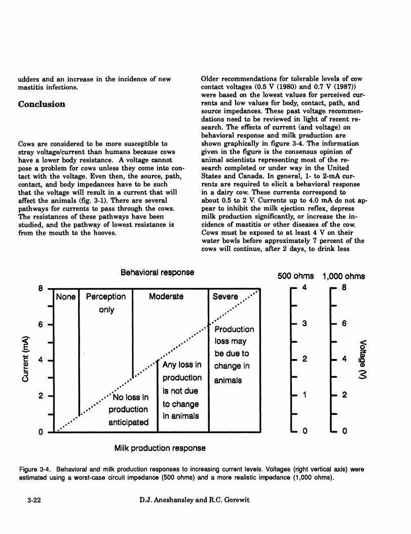
udders and an increase in the incidence of new mastitis infections.
Conclusion
Cows are considered to be more susceptible to stray voltage/current than humans because cows have a lower body resistance. A voltage cannot pose a problem for cows unless they come into con- tact with the voltage. Even then, the source, path, contact, and body impedances have to be such that the voltage will result in a current that will affect the animals (fig. 3-1). There are several pathways for currents to pass through the cows. The resistances of these pathways have been studied, and the pathway of lowest resistance is fi:*om the mouth to the hooves.
Older recommendations for tolerable levels of cow contact voltages (0.5 V (1980) and 0.7 V (1987)) were based on the lowest values for perceived cur- rents and low values for body, contact, path, and source impedances. These past voltage recommen- dations need to be reviewed in light of recent re- search. The effects of current (and voltage) on behavioral response and milk production are shown graphically in figure 3-4. The information given in the figure is the consensus opinion of animal scientists representing most of the re- search completed or under way in the United States and Canada. In general, 1- to 2-mA cur- rents are required to elicit a behavioral response in a dairy cow. These currents correspond to about 0.5 to 2 V. Currents up to 4.0 mA do not ap- pear to inhibit the milk ejection reflex, depress milk production significantly, or increase the in- cidence of mastitis or other disea&es of the cow. Cows must be exposed to at least 4 V on their water bowls before approximately 7 percent of the cows will continue, after 2 days, to drink less
Behavioral response
8
6 -
e 4
3 2 -
— None Perception
only
Moderate Severe .,♦*** .♦*
...••••■
Production loss may
be due to
♦ Any loss in change in
- ..••'•
production animals
-
.♦
..♦•* No loss in
..^** production
anticipated
is not due
to change in animals
500 ohms 1,000 ohms f- 4 r- 8
- 3
- 2
- 1
- 6
.4 I (D
- 3 - 2
- 0
Milk production response
Figure 3-4. Behavioral and mill< production responses to increasing current levels. Voltages (right vertical axis) were estimated using a worst-case circuit impedance (500 ohms) and a more realistic impedance (1,000 ohms).
3-22 D.J. Aneshansley and R.C. Gorewit

water. Most cows (more than 90 percent) adapt within 2 days to constant voltages as high as 6 V on the water bowls.
Based on current research, cow contact voltages from low impedance sources should be kept less than 2 to 4 V. Cow contact voltages between 1 and 4 V from low impedance sources may cause behavioral effects resulting in increased labor costs and/or inappropriate responses of farmers to the changes in behavior. These possible increased costs have to be balanced against the cost of reduc- ing voltages in the range of 1 to 4 V. Once cow contact voltages reach 1.0 V, a program of routine monitoring should be initiated to ensure that the voltages do not increase significantly.
It is doubtful that the milking machine plays a role in the exposure of cows to stray voltage. The voltage necessary to override the resistance of the milking path would be in excess of neutral-to- earth voltages.
Since cows acclimate physiologically and be- haviorally to the current or voltage levels men- tioned herein, it is very doubtful that they would react differently upon continuous long-term (more than 50 days) or intermittent long-term current ex- posure (more than 96 consecutive hours) to those currents.
Preliminary results from long-term experiments (21-day, 28-day, and full lactation exposures) sup- port this conclusion.
As mentioned earlier, cows experience various health problems, including mastitis. Mastitis is a fact of life in the dairy industry, and it is caused by infection of the udder and not electricity.
It should be reemphasized that factors such as mistreatment of cows, milking machine problems, disease, poor sanitation, and nutritional disorders may cause cows to manifest any of the symptoms that are associated with stray voltage/current problems.
Animals are quite variable in response to a specific current. Minnesota researchers found that mouth opening is a specific, current-elicited
response for the mouth-to-all-hooves pathway. No responses were observed during control (no cur- rent) trials; specific avoidance responses were ex- hibited 13.8 percent of the time at 1.0 mA of current, 30.0 percent of the time at 2.0 mA, 92.3 percent of the time at 4.0 mA; and 98.4 percent of the time at 5.0 mA.
The voltage required to elicit a response depends on the resistance of the pathway taken by the cur- rent through the cow's body. A number of such pathways have been examined. Differences among pathway resistances, including cow contact resis- tance, have been shown to be as great as sixfold or greater. While some pathway resistances ap- proach 1,000 ohms or more, worst-case resistances of specific cows on specific farms may be as low as 500 ohms. Voltage levels required to elicit the various behavioral responses are shown in figure 3-4.
Behavioral responses to stray voltage vary by cow and circumstance. Variations in responses are due to how the cows perceive current and not to dif- ferences in the ability of cows to feel current. Some important considerations in dealing with be- havioral responses to electrical stimulation are 1) that the farmer's reaction to behavioral chan- ges may magnify existing problems or even create new and more serious problems and 2) that even when the stray voltage is eliminated or effectively suppressed, behavioral problems may continue be- cause of the effects of conditioning.
Physiological Effects 3-23

4. Mitigation Robert Gustafson, editor
Summary
This chapter presents the various solutions to stray or neutral-to-earth voltage problems in live- stock facilities. The advantages and disadvantages of each are covered. The mitigation of existing problems and prevention of future problems demand careful consideration of electrical sources, animal sensitivity, and characteristics of the correc- tive procedures or devices. Effects of any mitiga- tion, by modifications of the electrical system on either the farmstead or distribution systems under normal and fault conditions, must be considered.
Approaches for controlling stray or neutral-to- earth voltages fall into four categories:
♦ Voltage reduction by mitigation of the causa- tive or exacerbating conditions (e.g., by remov- ing bad neutral connections and faulty loads; improving or correcting wiring and grounds; balancing loads; or controlling leakage cur- rents by cleaning, reinsulating, or grounding).
♦ Active suppression of the voltage by a nulling device.
♦ Gradient control by use of equipotential planes and transition zones to maintain the animals' step and touch potentials at an ac- ceptable level.
♦ Isolation of a portion of the groimding or grounded neutral system from the animals.
The most suitable approaches in any given situa- tion must be based on the available information and constraints of the specific situation. All of the corrective devices and procedures discussed are theoretically sound. All have their advantages and disadvantages. Specific concepts and devices will continue to evolve; however, the principles underly- ing the control of problem voltages have been clearly identified.
Understanding the characteristics of various volt- age problems, their interactions, and the effect of
corrective procedures can be enhanced through the use of circuit models. Gustafson and Hansen (1985) developed two personal computer programs useful in the analyses of single-phase, multi- grounded distribution and farmstead systems. The programs use resistive models to simulate systems with a single-phase multigrounded primary serv- ing 120/240-V single-phase farmsteads. Examples 1 and 2 of the appendix of this chapter are used to demonstrate electrical characteristics discussed within this chapter.
Other models have been developed with slightly different circuit parameters. However, the prin- ciples demonstrated and results obtained are similar to those of examples 1 and 2.
Mitigation 4-1

Voltage Reduction
If investigations show a troublesome level of neutral-to-earth voltage due to such conditions as the presence of 1) high resistance connections either on or off the farm, 2) neutral imbalance cur- rents on or off the farm, 3) imdersized neutrals, or 4) fault currents to earth or to equipment grounding conductors, corrections can be made and the remaining voltage assessed. Likely conse- quences of these conditions are presented in cases 5P, 6P, 8P, 9P, and lOP of example 1, and cases 3F, 5F, and 7F of example 2. The interaction of such conditions and the results of correction proce- dures, as discussed later, must be evaluated.
Reduction of grounding resistance on the distribu- tion neutral will reduce the neutral-to-earth volt- age due to system loading. This is demonstrated by cases 14P and 15P of example 1. Since the proportion of the system grounding supplied by the farmsteads is often large compared with that
supplied by the distribution neutral grounds, the effectiveness of this approach may be limited. It is important to recognize that much of the system grounding on the farmstead is supplied by items which are equipment grounded and in contact with the earth.
If the farmstead system contains long secondary neutrals, an option of using a four-wire service to an outbuilding is allowed by the National Electri- cal Code (NEC) of 1990. Use of a four-wire system as shown in figure 4-1 will reduce the contribu- tion of the secondary neutral voltage between the main service and outbuilding panel to the groimd- ing system at the outbuilding. Only the neutral-to- earth voltage on the grounding system at the main service will be '•arried to the outbuilding ground system by the fourth wire (the grounding conductor). Neutral-to-earth voltages will remain from all other sources. For the four-wire system, all neutral and grounding conductors in the out- building service and all feeders from that service must be completely separated. The originating end of the four-wire system must meet all NEC re- quirements as a service, i.e., disconnect with over-
TRANSFORMER
LOAD
OUTBUILOINO SERVICE
Figure 4-1. A four-wire feeder from farm main to outbuilding. Note that the neutral in the outbuilding is not bonded to the grounding bus (GR) but is bonded at the main service.
4-2 Robert Gustafson

HI H2 N
) ^\
NEUTRAL/GROUNDING ^l BAR
POWER INPUTS
SERVICE GROUNDING
ELECTRODE
SENSING INPUTS
1 NULLING DEVICE
J
REFERENCE =■ ELECTRODE
OUTPUT TO REMOTE ELECTRODE
REMOTE ELECTRODE
SYSTEM
Figure 4-2. Voltage suppression by controlled current to earth.
current protection, system grounding, appropriate enclosure, and neutral-to-ground bonding connec- tion. The equipment grounding conductors must have the same ampacity as the ungroimded con- ductors.
As discussed in the sources chapter, voltages may appear between metallic objects which are not bonded to the electrical system or equipment grounding. These voltages are commonly caused by what are termed "leakage currents." Leakage due to moisture and dirt or capacitive coupling can also occur. In rare instances leakage currents may arise that are strong enough to cause problems for animals. As described in the measure- ment chapter, careful testing procedures should be followed to assess current-producing capability. Mitigation involves groimding or bonding of metal- lic structures and may also require cleaning, repositioning, and adding of drainage holes to deal with moisture and dirt.
Active Voltage Suppression
Since voltage is produced by current flow through a system impedance, a second source of current may be used to null or cancel the original source at a point in the system. One procedure used to mitigate neutral-to-earth voltage, as demonstrated by cases IIP, 12P, and 13? of example 1, is to deliver a controlled current to earth (fig. 4-2). Volt- age between a point in the neutral/groimding sys- tem and an isolated reference ground or grounds is used as the input to a differential amplifier. Current delivered to a remote-grounding-electrode system is then adjusted to null out the measured voltage. A description of this method is given by Winter and Dick (1983). Comparison of the sup- pressed cases to the base case in example 1 demonstrates that the voltage is also reduced along the line for farms near the location of the device. Power required for the compensating cir- cuit depends on the required current and resis- tance of the remote-grounding-electrode system. In the example, for the device near the middle of a 10-farm line, the power required would be ap-
Mitigation 4-3

proximately 250 W for a 10-ohm remote-electrode system.
Two advantages of this approach are that 1) instal- lation of a nulling imit requires no modification of the basic existing electrical system, so if this sys- tem has been properly wired the full safety benefits of the interconnected grounded neutral system would be retained and 2) nulling of the neutral-to-earth voltage at a point lowers the level of neutral-to-earth voltage on the distribution sys- tem.
Disadvantages include 1) possible maintenance problems inherent to active (amplifier system) type devices, 2) high initial cost, and 3) the poten- tial for offsetting problem sources which should be corrected by other means. Existing units limit the offset capabilities to a level that should not sig- nificantly affect the operation of overcurrent protection devices imder fault conditions.
Gradient Control
Gradient control by equipotential planes will negate the effects of all neutral-to-earth voltages in livestock facilities if they reduce the potential differences at all possible animal contact points to an acceptable level. Gradient control is used by the electrical industry to minimize the risk of haz- ardous step (foot-to-foot) and touch (hand-to-foot) potentials under fault conditions at substations and aroiuid electrical equipment. In addition to protecting people, animals, and equipment under fault or lightning conditions, proper equipotential systems in livestock facilities can solve stray volt- age/current problems. They also provide an addi- tional system-grounding electrode. Equipotential planes add to the electrical safety of humans and animals,
Equipotential Plane The definition of the equipotential plane is derived from two words. Equipotential means having the same electrical potential throughout; plane means a flat or level surface, together they form a level surface having the same electrical potential throughout.
Any animal standing on the floor containing a properly installed equipotential plane will have all possible contact points at or very near the same potential. Figure 4-3 shows animals on equipoten- tial planes. Equipotential planes can alleviate stray voltage / current problems only in areas where they have been properly installed.
Some areas where an equipotential plane might be installed are stanchion bams, tie-stall bams, free-stall barns, milking parlors (including operator pit and holding areas), and around electri- cally heated waterers and mechanical feed bunks.
A properly installed equipotential plane must in- clude all of the following: 1) Equipment ground- ing, 2) metalwork bonding, and 3) a conductive network in the floor bonded to the electrical sys- tem grounding.
If an equipotential plane is properly installed, the only possible concern is that the animals will receive an electrical shock when they move on or off the plane as shown in figure 4-4. If the neutral- to-earth voltage is high enough to force an unac- ceptable current through the animals' bodies from the front to rear hooves they may refuse or be reluctant to move on or off the equipotential plane. This voltage problem can be reduced sub- stantially (but not totally eliminated) by a voltage gradient ramp. A properly constructed voltage ramp subjects the animals to an acceptable
VOLTMETER SHOWS A STEP POTENTIAL
Figure 4-4. Animal approaching an equipotential plane.
4-4 Robert Gustafson

METAL WATER PIPE
METAL STALL PIPES
VOLTMETER SHOWS NO VOLTAGE FROM PIPE TO FLOOR
6"x 6" REINFORCING MESH
REINFORCING ROD TIES ALL PARTS OF THE MESH TOGETHER
METAL WATER PIPE
VOLTMETER SHOWS NO VOLTAGE FROM PIPE TO FLOOR
Figure 4-3. Animals on equipotential planes. All body contacts are at the same potential.
Mitigation 4-5
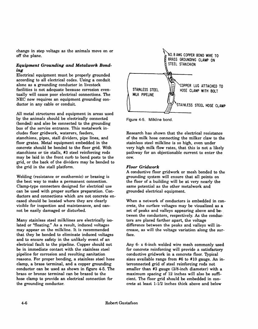
change in step voltage as the animals move on or off the plane.
Equipment Grounding and Metalwork Bond- ing Electrical equipment must be properly grounded according to all electrical codes. Using a conduit alone as a grounding conductor in livestock facilities is not adequate because corrosion even- tually will cause poor electrical connections. The NEC now requires an equipment groimding con- ductor in any cable or conduit.
All metal structures and equipment in areas used by the animals should be electrically connected (bonded) and also be connected to the grounding bus of the service entrance. This metalwork in- cludes floor gridwork, waterers, feeders, stanchions, pipes, stall dividers, pipe lines, and floor grates. Metal equipment embedded in the concrete should be bonded to the floor grid. With stanchions or tie stalls, #3 steel reinforcing rods may be laid in the front curb to bond posts to the grid, or the back of the dividers may be bonded to the grid in the stall platform.
Welding (resistance or exothermic) or brazing is the best way to make a permanent connection. Clamp-type connecters designed for electrical use can be used with proper surface preparation. Con- ductors and connections which are not concrete en- cased should be located where they are clearly visible for inspection and maintenance, and can- not be easily damaged or disturbed.
Many stainless steel milklines are electrically iso- lated or "floating." As a result, induced voltages may appear on the milkline. It is recommended that they be bonded to eliminate induced voltages and to ensure safety in the unlikely event of an electrical fault to the pipeline. Copper should not be in immediate contact with the stainless steel pipeline for corrosion and resulting sanitation reasons. For proper bonding, a stainless steel hose clamp, a brass terminal, and a copper grounding conductor can be used as shown in figure 4-5. The brass or bronze terminal can be brazed to the hose clamp to provide an electrical connection for the grounding conductor.
i^. 10.8 AWG COPPER BONO WIRE TO BRASS GROUNDING CLAMP ON STEEL STANCHION
STAINLESS STEEL MILK PIPELINE
OPPER LUG ATTACHED TO HOSE CLAMP WITH BOLT
^ ^STAINLESS STEEL HOSE CLAMP
Figure 4-5. Milkline bond.
Research has shown that the electrical resistance of the milk hose connecting the milker claw to the stainless steel milkline is so high, even under very high milk flow rates, that this is not a likely pathway for an objectionable current to enter the cow.
Floor Gridwork A conductive floor gridwork or mesh bonded to the grounding system will ensure that all points on the floor of a building will be at very nearly the same potential as the other metalwork and groimded electrical equipment.
When a network of conductors is embedded in con- crete, the surface voltages may be visualized as a set of peaks and valleys appearing above and be- tween the conductors, respectively. As the conduc- tors are placed farther apart, the voltage difference between the peaks and valleys will in- crease, as will the voltage variation along the sur- face.
Any 6- x 6-inch welded wire mesh commonly used for concrete reinforcing will provide a satisfactory conductive gridwork in a concrete floor. Typical sizes available range from #6 to #10 gauge. An in- terconnected grid of steel reinforcing rods not smaller than #3 gauge (3/8-inch diameter) with a maximum spacing of 12 inches will also be suffi- cient. The floor grid should be embedded in con- crete at least 1-1/2 inches thick above and below
4-6 Robert Gustafson

to protect the metal from corrosion due to mois- ture and manure.
The specific arrangement and procedures for properly installing floor gridwork will vary with the type of facility and construction practices. The following guidelines and recommendations are based on the test results and experiences with field installations as well as extensive laboratory testing. A general procedure that has proven very satisfactory is to install an interconnecting grid of steel reinforcing rods that serves as a base.for a continuous overcovering of welded wire mesh. The location and spacing of the base reinforcing rods is not critical. In stanchion- or tie-stall facilities, two rods spanning the full length of the floor and three or four placed at intermediate locations across the floor have proved effective.
New Construction All concrete floors installed in new or remodeled confinement livestock facilities should include an equipotential plane. The installation procedure may vary, depending on the type of facility and construction practices. The wire mesh or reinforc- ing rods are laid out in the floor area. Before the concrete is poured, the mesh is bonded to all equipment, stalls, and partitions that are to be em- bedded in the concrete. The bonds in the grid should be checked before the concrete is poured to ensure that they're electrically sound. Any equip- ment not embedded in concrete should also be bonded to the mesh in an appropriate manner to provide electrical continuity at all surfaces. Provision should be made to allow an exposed means of bonding the equipotential plane to the groimding electrode system. This provision will allow the bond to be visually inspected in the fu- ture.
The size of the wire in the mesh or the size of the reinforcing rods is not critical except as related to the possible deterioration through corrosion, etc. Number-10 welded wire mesh (6 by 6 inches) and #3 gauge (3/8 inch) reinforcing rods should be satisfactory.
Figure 4-6 shows a typical layout of the reinforc- ing-rod base grid auid overlying mesh in a stall
dairy bam. Figure 4-7 shows an equipotential plane in a milking parlor.
The following recommendations should be con- sidered when designing an eqmpotential plane for any livestock facility:
♦ All intersections of the reinforcing rods in the base grid should be solidly welded together (see figs. 4-6 and 4-7).
♦ All reinforcing rods in the base grid should span the full length or width of the building.
♦ The cross-reinforcing rods in a stall dairy barn should be bent to go underneath the gut- ter.
♦ The milking parlor plane must include the operator's pit.
♦ The floor gridwork should extend into the hold- ing and exit areas and/or a transition ramp should be installed where the animals move onto and off the floor.
♦ At intervals (every three or four strands), the welded wire mesh should be tack welded or brazed to the crosswise reinforcing rods where they intersect.
♦ Where convenient, the reinforcing rods should be welded to the metalwork in the building. For example, the lengthwise reinforcing rods in a stall dairy barn may be welded to the rear pipes of the stall dividers.
♦ It is preferable to position the equipotential plane so that the mesh is in the center or upper portion of the concrete floor, (1-1/2 to 2 inches from both surfaces).
It is not necessary to include mesh in the floor of the gutter or to extend the mesh through narrow concrete curbs, such as the curb at the fi*ont of the stall dividers in a stall dairy bam, which may be poured before the floor. However, when the mesh is installed in the floor, it should extend up to the edges of any such curbs.
Mitigation 4-7
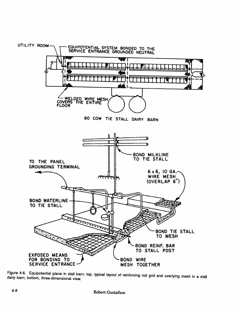
UTILITY ROOM EOUiPOTENTiAL SYSTEM BONDED TO THE SERVICE ENTRANCE GROUNDED NEUTRAL
mmxfiiaiibuiLLLLLLi i4in
th-rrrntrrrrm|bd±mi^m
/-,^v.Äii-DED WIRE MESH COVERS THE ENTIRE FLOOR
60 COW TIE STALL DAIRY BARN
TO THE PANEL GROUNDING TERMINAL
BONO WATERLINE TO TIE STALL
Ï BOND MILKLINE TO TIE STALL
6x6, 10 GA. WIRE MESH (OVERLAP 6")
BOND TIE STALL TO MESH
BONO REINF. BAR TO STALL POST
EXPOSED MEANS FOR BONDING TO SERVICE ENTRANCE
BONO WIRE MESH TOGETHER
öZVJ: .!rr^:a^Ji:!f!'^''' ^^P- ^-^^^^ '^^-^ °^ -"^--g ^«^ 9"^ and ovenying mesh i dairy barn; bottom, three-dimensional view. in a stall
4-8 Robert Gustafson
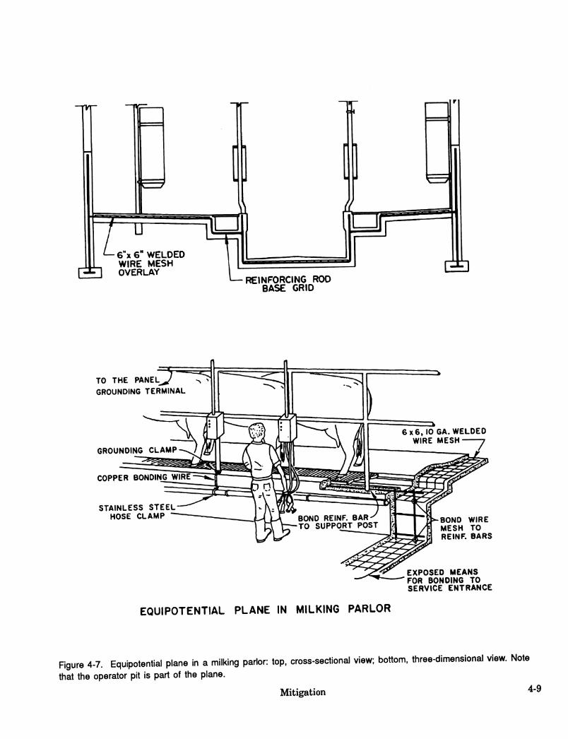
i]
r 7 TJ
6"x 6" WELDED WIRE MESH OVERLAY
REINFORCING ROD BASE GRID
TO THE PANEL GROUNDING TERMINAL
GROUNDING CLAMP
COPPER BONDING WIRE
STAINLESS STEEL HOSE CLAMP
6 X6J0 6A. WELDED WIRE MESH "7
BOND WIRE MESH TO REINF. BARS
EXPOSED MEANS FOR BONDING TO SERVICE ENTRANCE
EQUIPOTENTIAL PLANE IN MILKING PARLOR
Figure 4-7. Equipotential plane in a milking parlor: top. cross-sectional view; bottom, three-dimensional view. Note
that the operator pit is part of the plane.
Mitigation 4-9

Proper performance of an equipotential plane depends on positive electrical continuity between the reinforcing rod base, the welded wire mesh, all metalwork in the facility, and the system electrical ground at the service entrance to the building. Mul- tiple connections will help ensure electrical con- tinuity of all components. Where possible, stanchion or stall pipework can be welded or clamped to the reinforcing rod base or welded wire mesh by using short sections of reinforcing rod. It is not necessary to provide connections be- tween every pipe and the equipotential plane, but a few distributed throughout the facility will help ensure electrical continuity. The equipotential plane and its associated metalwork can be bonded to the service-entrance-system groxmd by extend- ing one of the reinforcing rods into a convenient location in the building, where it is bent upward to project above the concrete. A groimding conduc- tor (AWG #6 or larger copper wire ) can then be clamped to the rod and connected to the service- entrance grounding bus.
Voltage Ramp (Gradiant Control) An animal may be affected when it steps onto or off the floor of the equipotential plane. A properly constructed voltage ramp will reduce the potential effect by providing a more gradual change in volt- age at the perimeter of the plane. The voltage dif- ference between an animal's front and rear hooves cannot be totally eliminated as it moves on or off the plane. However, the difference can normally be reduced to an acceptable level.
Based on the results of laboratory tests, an effec- tive voltage ramp can be provided at animal entrance and exit locations by essentially extend- ing the equipotential plane outward and downward at a 45-degree angle as shown in figure 4-8.
The voltage ramp can be made by driving or bury- ing 8- or 10-foot copper-clad ground rods into the soil at an angle to the surface. The rods should be no more than 12 inches apart, and enough should be used to span the width of the access path. The rods should be installed at a 45-degree angle (1:1 slope) to the surface.
rVS
DOORWAY
PARLOR FLOOR >
BONDING TO EQUIPOTENTIAL PLANE
[4-6* STEP HOLDING r AREA
Parlor
m ÎT
J BONDING -^
CONDUCTOR ([GROUND RODS^
45* angle V Holding
Area
Figure 4-8. Voltage ramp adjacent to an equipotential plane: top, side view; bottom, frontal view.
Electrical connections to the equipotential plane and to the copper-clad ground rods should be en- cased in concrete. The ground rods for the voltage ramp should be installed at the time the reinforc- ing-rod base grid and welded wire mesh are laid out for the equipotential plane. A section of rein- forcing rod should be attached to the end of the mesh across the access area. The 45-degree rods are then bonded to this reinforcing rod.
Retrofitting Existing Facilities
There are two practical ways to retrofit existing facilities with equipotential systems. If possible, the preferred way is to fabricate the equipotential plane, as explained earlier, over the entire exist- ing floor in the facility and pour a 2-inch overlay of concrete. Retrofitting in this way can be practi- cal in a milking parlor facility but may not be
4-10 Robert Gustafson

feasible in a stall barn. Sometimes a partial plane is adequate. For example, an eqiiipotentail plane could be installed for the cow platforms and operator's pit in a milking parlor. If the problem in the parlor is solved, no more may need to be done. If the problem remains, additional steps can be taken. For example, if the cows are reluctant to enter the parlor, a voltage ramp may be neces- sary. In a stall bam, it may be possible to retrofit a section of the cow platform. If doing so solves
•5-^4 SOLID COPPERWIRE
the problem, the remainder of the cow platform can be retrofitted. If the cows are then reluctant to step across the gutter, it may be necessary to retrofit the center walkway also.
Another way to retrofit an existing facility with an equipotential plane is to saw grooves in the ex- isting concrete floor and grout in copper conduc- tors that are electrically interconnected to the metalwork in the facility, all of which are then
-OVERHEAD BOND
STALL " PLATFORM TfW
Ft t:
-TRANSITION ^^^^^^ j ^^LEY F
— -y^ FEED T^^MANGER -*
/I '"■"^* BOND TO I I SERVICE PANEL z EQUIPOTENTIAL PLANE
BONO T0= WATERLINE. STANCHIONS, PIPELINE Figure 4-9. Retrofit equipotential plane in stanchion/tie stall barn.
BOND TO STALLS
EQUIPOTENTIAL PLANE #4 SOLID COPPERWIRE (DASHED LINES)
BOND TO MILKLINE AND STALLS
-^^ND TO SERVICE PANEL
Figure 4-10. Retrofit equipotential plane in milking parlor.
Mitigation 4-11

equipment grounded to the service entrance. This method involves grooving the concrete about 1 to 1-1/2 inches deep and 1/4 inch wide, then laying AWG #4 soft copper wire into the grooves and grouting over the grooves. Wires should be placed in the feed manger, front hoof area, and rear hoof area. For example, in a stall bam like that shown in figure 4-9, two conductors spaced 12 inches apart could be located 6 to 10 inches from the edge of and parallel to the gutter. These conduc- tors would provide the system for the back feet. Two conductors spaced 12 inches apart are placed 6 to 10 inches from and parallel to the front curb to take care of the front feet area. One conductor is placed 6 to 10 inches from the front curb in the manger. Welds or pressure-type connections are used to bond these wires together at several points along the length of the barn. At a mini- mum, the wires should be bonded at each end of the barn and to the stallwork and water line. The exothermic weld, or CADWELD, is particularly good for bonding the copper wires together and to steel posts or other equipment. A quick-setting grout will speed installation. A grout approved by the Department of Health and Human Services' Food and Drug Administration should be used in the manger area, because of its proximity to animal feed. Milking parlors and holding areas can also be retrofitted by this method (fig. 4-10). Wires are spaced 12 to 18 inches apart and are placed in the cow platform area and entrance and exit alleys. Wires should also be placed in the operator pit. To be effective the copper conductors must be interconnected at the end and bonded to the electrically interconnected stallwork. The en- tire system must then be equipment grounded to the electrical service entrance. This method of retrofitting allows use of the facility during con- struction, since most of the work can be per- formed between milkings.
Isolation
of the grounded neutral system can prevent neutral-to-earth voltages on the nonisolated por- tion of the system from accessing the animals. Isolation can be accomplished at either of two sites of a conventional multigrounded system: 1) ahead of the farm main service (whole farm isolation) and 2) at the livestock building single service (single servive isolation). Careful considera- tion must be given to the safety and operational ef- fects if isolation is used.
Whole Farm Isolation
Whole farm isolation can be accomplished 1) at the distribution transformer or 2) with an isola- tion transformer following the distribution trans- former. The important features of these approaches will be discussed. In all cases some system grounding will be removed from the dis- tribution system, at least during nonfault condi- tions. As will be shown, this can affect both on- and oflF-farm sources of neutral-to-earth voltage.
Effect of Isolation on the Primary Neutral Under nonfault conditions, isolation of the farmstead removes its grounding from the grounded neutral system of the distribution primary. This removal increases both the ground- ing resistance of the distribution neutral system and the neutral-to-earth voltage on the primary. Such neutral-to-earth voltage increases resulting from the isolation of one or more farmsteads imder nonfault conditions along a 10-farm, single- phase line are modeled in cases 2P, 3P, and 4P of example 1 (appendix). The effect of isolation of farmsteads along the line diminishes with dis- tance from isolation. However, isolation raises the concern that neutral-to-earth voltages may be raised to a problem level at farms or residences in close proximity. In these cases further action may be necessary to maintain or reduce the neutral-to- earth voltage.
The term "isolation" is used to describe electrical separation of all or a portion of the grounded neutral system of a farmstead from the remainder of the power distribution system. Isolation of part
Effect of Neutral Isolation on the Secondary Neutral Whole farm isolation removes contributions from off-farm sources. However, it will also affect on- farm sources resulting from secondary-neutral volt- age drops and on-farm faults. Changes in magnitude of neutral-to-earth voltages resulting
4-12 Robert Gustafson
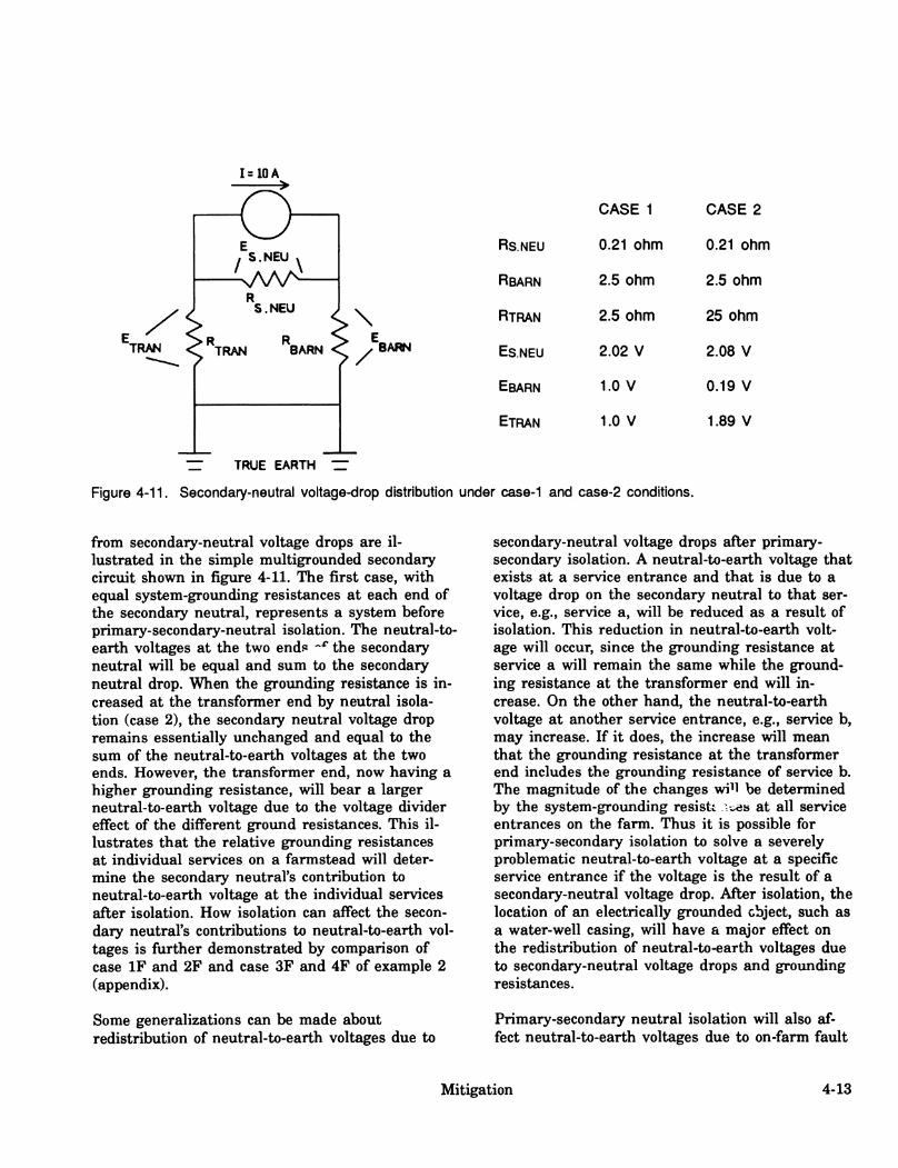
I=10A
o / S.NEU .
s. NEU
TRAN TRAN BARN
\
BARN
CASE 1 CASE 2
RS.NEU 0.21 ohm 0.21 ohm
RBARN 2.5 ohm 2.5 ohm
RTRAN 2.5 ohm 25 ohm
Es.NEU 2.02 V 2.08 V
EBARN 1.0 V 0.19 V
ETRAN 1.0 V 1.89 V
— TRUE EARTH ZT
Figure 4-11. Secondary-neutral voltage-drop distribution under case-1 and case-2 conditions.
from secondary-neutral voltage drops are il- lustrated in the simple multigrounded secondary circuit shown in figure 4-11. The first case, with equal system-groimding resistances at each end of the secondary neutral, represents a system before primary-secondary-neutral isolation. The neutral-to- earth voltages at the two endi^ -^^ the secondary neutral will be equal and sum to the secondary neutral drop. When the grounding resistance is in- creased at the transformer end by neutral isola- tion (case 2), the secondary neutral voltage drop remains essentially imchanged and equal to the sum of the neutral-to-earth voltages at the two ends. However, the transformer end, now having a higher groimding resistance, will bear a larger neutral-to-earth voltage due to the voltage divider effect of the different ground resistances. This il- lustrates that the relative grounding resistances at individual services on a farmstead will deter- mine the secondary neutral's contribution to neutral-to-earth voltage at the individual services after isolation. How isolation can affect the secon- dary neutral's contributions to neutral-to-earth vol- tages is further demonstrated by comparison of case IF and 2F and case 3F and 4F of example 2 (appendix).
Some generalizations can be made about redistribution of neutral-to-earth voltages due to
secondary-neutral voltage drops after primary- secondary isolation. A neutral-to-earth voltage that exists at a service entrance and that is due to a voltage drop on the secondary neutral to that ser- vice, e.g., service a, will be reduced as a result of isolation. This reduction in neutral-to-earth volt- age will occur, since the groxmding resistance at service a will remain the same while the groimd- ing resistance at the transformer end will in- crease. On the other hand, the neutral-to-earth voltage at another service entrance, e.g., service b, may increase. If it does, the increase will mean that the grounding resistance at the transformer end includes the grovmding resistance of service b. The magnitude of the changes wi^l be determined by the system-grounding resistt i-^h at all service entrances on the farm. Thus it is possible for primary-secondary isolation to solve a severely problematic neutral-to-earth voltage at a specific service entrance if the voltage is the result of a secondary-neutral voltage drop. After isolation, the location of an electrically grounded object, such as a water-well casing, will have a major effect on the redistribution of neutral-to-earth voltages due to secondary-neutral voltage drops and groimding resistances.
Primary-secondary neutral isolation will also af- fect neutral-to-earth voltages due to on-farm fault
Mitigation 4-13

currents to earth. Since the resistance of the return path of such a fault current to the trans- former is increased, the contribution of neutral-to- earth voltage will be increased proportionally. The fault current can create a neutral-to-earth voltage either in phase or 180 degrees out of phase with other existing neutral-to-earth voltages, resulting in a net increase or decrease. Cases 5F through 8F of example 2 demonstrate these effects.
Available Devices for Neutral Isolation Devices are now available to provide primary-to- secondary-neutral isolation at the distribution transformer in conformance with section 97D of the National Electrical Safety Code (NESC) of 1990. The NESC applies to transmission and dis- tribution systems. The major safety concern is for the prompt interruption of service to the customer in the event of 1) a winding-to-winding fault in the distribution transformer or 2) a primary con- ductor short to a service conductor. Sufficient fault current must pass from the customer service to the primary system to ensure operation of the line overcurrent protection or transformer fuse. As a result of this concern, the groxmding committee of the NESC modified the 1984 code to require the isolating device to have a 3-kV-or-less, 60-Hz breakdown voltage.
Although the NESC deems a 3-kV-device suitable for providing the necessary consumer safety, some persons involved with isolation for animal confine- ment have the opinion that the lower the sparkover voltage, the safer. The risk is related to high voltage directly entering a household or cus- tomer premise. This risk exists even without isola- tion. Therefore, any safety benefit of such devices must be quantified through the reduction in fault clearing time (fuse or circuit breaker action).
Since the change in the 1984 NESC to specify isolation devices with a breakdown voltage of 3 kV or less, three methods have been developed for isolating the primary and secondary neutrals at the distribution transformers. They make use of 1) conventional spark gap, 2) a saturable reactor, or 3) a solid state switch. These methods provide a high impedance interconnect below a specified threshold voltage and a low impedance intercon- nect when the voltage exceeds that threshold. The
"high** impedance is relative to the grounding im- pedance of the isolated secondary system. The "low^ impedance provides that under any condi- tion creating a primary-to-secondary voltage above the threshold level, the device impedance will be reduced to the extent that the neutrals are essen- tially bonded. As discussed in the following sec- tion, under normal operation these devices will affect neutral-to-earth voltages on both the primary and secondary systems.
Low Voltage Lightning Arresters: Several types of conventional, low-voltage lightning arresters are being used for primary-secondary-neutral isola- tion. Since most of these gaps are designed as low- current devices, their use may be restricted to systems with appropriate limitations on fault cur- rents.
Saturable Reactors: Saturable reactors designed to give an impedance-change threshold in the range of 10 to 24 V ac are also in use. Figure 4- 12 shows the apparent impedance characteristics of three such devices as a fimction of the root means square (rms) voltage (Vrms) (60 Hz) across the device. Below saturation voltage, the high im- pedance provides isolation. Above saturation, the impedance drops to a very low level to provide neutral interconnection. As discussed below, when peak voltages are above the saturation threshold, part-cycle conduction will create a nonsinusoidal neutral-to-earth voltage on the secondary. These devices also include a lightning (surge) arrester to divert fast-rising transient voltages, such as lightn- ing voltages. Such transients would otherwise cre- ate high voltages across the reactors.
Solid State Switch: The solid state switching device is equipped with two thyristors and a con- trol circuit for each. The control circuit triggers the thyristors when an instantaneous voltage above the specified threshold occurs across the device. For a 60-Hz waveform whose peak is above the threshold, the device triggers during each half cycle and remains closed for the remainder of the half cycle. This device also has a surge arrester in parallel to assist in passing fast rising transients.
4-14 Robert Gustafson

3000
2000
_ 1000
E 800 600 < 500
10 400 E w 300 >
200 ilJ o 1 100 Q UJ
80 a. 60 S 50 •■" 40 z 30 UJ a: 20 < a. Q. < 10
8 6 5 4 3
O DEVICE A (Rdcûf0.007ohm)
X DEVICE B (Rdci^0J45ohm)
¿i DEVICE C
2-
4 6 8 10 12 14 16 18 20 22 24 26 28 30
rms VOLTAGES ACROSS DEVICE (Vrms)
Figure 4-12. Apparent impedance characteristics of three saturable reactors, where Arms=rms amperages.
Characteristics During Part-Cycle Saturation or Triggering: Under certain conditions, the voltage between the groxinded-neutral systems of the primary and secondary can saturate or trigger the isolation device during part cycles (Gustafson et al. 1985c). Such a condition can occur, for ex- ample, when a short-term large load (as from a large-motor start) is placed on the distribution sys- tem. The resulting voltages will cause partial
saturation of saturable reactors or will create part- cycle closure of the solid state switch. Either ac- tion will lead to the development of a non-sinusoidal neutral-to-earth voltage on the secondary grounded neutral.
To demonstrate the characteristics of devices near saturation or a triggering level, the circuit shown in figure 4-13 was used. In the circuit, Rp repre-
Mitigation 4-15

t -Ep- n > R source
Device
< <
> >Rp=2ohms
-EF-
? 1 Rp =2 ohms^ Voriable Source
Figure 4-13. Isolation device test circuit. Values for Ep and Ep are shown in figure 4-14. (Subscripts P and F stand for primary and farmstead, respectively.)
sents the lumped resistance of the groiinded- neutral system of the primary and RF the lumped resistance of the groimded-neutral system of the farmstead. An analysis was made of rms and peak voltages and of the waveform under varying condi- tions at or near the saturation or triggering level. Figure 4-14 shows typical waveforms for the Ep and EF. Figure 4-15 shows both the peak and rms values of EF as a function of Ep for three saturable reactors. Human and animal sensitivity in the 60-Hz frequency range for this non- sinusoidal waveform is proportional to the peak current. Since most volt-ohm meters commonly used for monitoring and troubleshooting read average or rms values, they will not provide the necessary data on neutral-to-earth voltages occur- ring at or near the saturation or triggering level. A voltmeter that can detect peak voltages or an os- cilloscope-type instrument will be needed.
Whole Farm Isolation With Isolating Ttans- former Isolating transformers such as the transformer shown schematically in figure 4-16 have been used extensively in the past to create a separate groimded neutral system on the farmstead. In this system, a primary-to-secondary fault current in the distribution transformer is carried by the dis- tribution system's neutral and groimding. An isolating transformer represents an investment in the range of $1,000 to $3,000, plus the cost of operating losses of the transformer. Care must be taken to ensure installation according to prevail-
20 22 24
E SOURCE (Vrmt)
26
16 16 20 22 24 26 26 30
E SOURCE (Vrmt)
11.00 11.25 11.50 11.75 12.00 12.25
E SOURCE (Vrmt)
Figure 4-15. Peak and rms voltages vs. source volt- age for three saturable reactors.
ing codes and recommendations, particularly for overcurrent protection, bonding, and grounding.
4-16 Robert Gustafson

o V .
o V -
Ep (Primory}
Seoles: Vert. 20 V/OIV Horis . 2 Nis/Oiv
Cp (F«nnsteod)
(o) Sotvroble Reoctor
O V-
0 V-
E_ (Primory)
Seoles Vert. 20 V/OIV Horlt. 2 mt/OlV
tf { Formsteod )
(b) Solid Stote Switch
Figure 4-14. Part-cycle saturation and triggering waveforms.
Mitigation 4-17
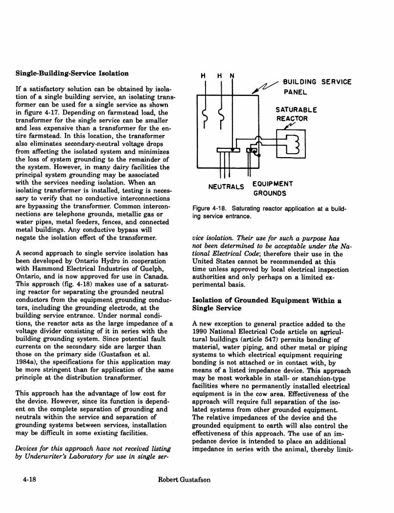
Single-Building-Service Isolation
If a satisfactory solution can be obtained by isola- tion of a single building service, an isolating trans- former can be used for a single service as shown in figure 4-17. Depending on farmstead load, the transformer for the single service can be smaller and less expensive than a transformer for the en- tire farmstead. In this location, the transformer also eliminates secondary-neutral voltage drops from affecting the isolated system and minimizes the loss of system grounding to the remainder of the system. However, in many dairy facilities the principal system grounding may be associated with the services needing isolation. When an isolating transformer is installed, testing is neces- sary to verify that no conductive interconnections are bypassing the transformer. Common intercon- nections are telephone groimds, metallic gas or water pipes, metal feeders, fences, and connected metal buildings. Any conductive bypass will negate the isolation effect of the transformer.
A second approach to single service isolation has been developed by Ontario Hydro in cooperation with Hammond Electrical Industries of Guelph, Ontario, and is now approved for use in Canada. This approach (fig. 4-18) makes use of a saturat- ing reactor for separating the grounded neutral conductors from the equipment grounding conduc- tors, including the groimding electrode, at the building service entrance. Under normal condi- tions, the reactor acts as the large impedance of a voltage divider consisting of it in series with the building grounding system. Since potential fault currents on the secondary side are larger than those on the primary side (Gustafson et al. 1984a), the specifications for this application may be more stringent than for application of the same principle at the distribution transformer.
This approach has the advantage of low cost for the device. However, since its function is depend- ent on the complete separation of grounding and neutrals within the service and separation of groimding systems between services, installation may be difficult in some existing facilities.
Devices for this approach have not received listing by Underwriter's Laboratory for use in single ser-
H H N BUILDING SERVICE
PANEL
SATURABLE REACTOR
NEUTRALS EQUIPMENT
GROUNDS
Figure 4-18. Saturating reactor application at a build- ing service entrance.
vice isolation. Their use for such a purpose has not been determined to be acceptable under the Na- tional Electrical Code; therefore their use in the United States cannot be recommended at this time unless approved by local electrical inspection authorities and only perhaps on a limited ex- perimental basis.
Isolation of Grounded Equipment Within a Single Service
A new exception to general practice added to the 1990 National Electrical Code article on agricul- tural buildings (article 547) permits bonding of material, water piping, and other metal or piping systems to which electrical equipment requiring bonding is not attached or in contact with, by means of a listed impedance device. This approach may be most workable in stall- or stanchion-type facilities where no permanently installed electrical equipment is in the cow area. Effectiveness of the approach will require full separation of the iso- lated systems from other grounded equipment. The relative impedances of the device and the grounded equipment to earth will also control the eflFectiveness of this approach. The use of an im- pedance device is intended to place an additional impedance in series with the animal, thereby limit-
4-18 Robert Gustafson

MAIN OISCONNCCT
WITH OVCRCU«RCNT PROTCCTION
TO OlSTAieUTlON
TRANSFORMER
SCCOMOARY
TRANSFORMER CASE SONOEO TO
SUPPLY SIDE ONLY
SURGE
ARRESTER
L. Í 1
ffl L__^_Li
BUILDING SERVICES
Figure 4-16. Isolating transformer installation, whole farmstead.
FARMSTEAD MAIN DISCONNECT
n
-t-o- ii.,r. I 3—t
TO OlSTRieuTlON
TRANSFORMER
SECONDARY
TIUIfSR)RMER DISCONNECT f
AND OVERCURNENT |
PROTECTION I
^
TRANSFORMER CASE aONOEO TO
SUPPLY SIDE ONLY
SURGE ARRESTER
I 1 III 1
r -/I
/
I [^
OTHER SERVICE
ISOLATING
TRANSFORMER ANY LOW RESISTANCE INTERCONNECTION
^WILL BY-FASS THE ISOLATION
TRANSFORMER AND RENDER THE
TRANSFORMER INEFFECTIVE
Figure 4-17. Isolation transformer installation, single service.
Mitigation 4-19
ing the current that any neutral-to-earth voltage on the system can force through the animal.
Conclusion
Four methods (voltage reduction, active suppres- sion, gradient control, and isolation) are available for dealing with stray voltage/current problems. Since most on-farm sources of stray voltage/cur- rent can be adequately dealt with by improvement of wiring, grounding, load balancing, reduction of leakage, and elimination of faults (voltage reduc- tion), the principal development work has been concentrated on methods for dealing with oflF-farm sources.
The most common off-farm source is the inherent impedance of the groxmded-neutral system of the primary. Since it will not always be practical to lower the neutral impedance or primary groimd- ing resistance to the extent of precluding the development of problem voltages for livestock, other measures for protecting livestock from stray voltage/currents are being explored. The on-farm techniques of voltage reduction, active voltage sup- pression, gradient control, and isolation are op- tions which can be considered. Further work is needed to help the electrical industry develop and select appropriate approaches that meet the needs of specific situations.
There are also situations in which electrical problems on adjacent farms or residences can af- fect the distribution primary's neutral-to-earth volt- age at a farm. These situations are due to the common interconnection of secondary neutrals to the primary neutral at each of the farms or residencies. Identification and mitigation of these problems at other locations may solve a neutral-to- earth problem at a specific farm.
4-20 Robert Gustafson

Appendix: Examples
Understanding the characteristics of various volt- age problems, their interactions, and the effect of corrective procedures can be enhanced through the use of circuit models. Gustafson and Hansen (1985) developed two personal computer programs useful in the analyses of single-phase, multi- groimded distribution and farmstead systems. The programs use resistive models to simulate systems with a single-phase multigrounded primary serv- ing 120/240-V single-phase farmsteads. Examples 1 and 2, below, are used to demonstrate electrical characteristics discussed within this chapter.
Other models have been developed with slightly different circuit parameters. However, the prin- ciples demonstrated and results obtained are similar to those of examples 1 £Uid 2.
Example 1. Single-Phase Distribution Line
Neutral-to-earth voltages (voltages across Roi) for a series of cases based on a model with a single- phase distribution line and certain assumed parameters are shown in figure 4-Al.
Case IP — Base-Case In case IP, the base-case neutral-to-earth voltages are due strictly to the loading of the distribution system (fig. 4-A2).
R L1
hA/WS^AAAAf
R Li
Rw Rw --'\/\/\/^-TTAAA/^—
R, R G1 :v. NE1 :R F1 R Gi :v, NEi :R Fi F10
Earth
Figure 4-A1. Ten-farm, single-phase-line model, where
E = Substation voltage source: 7,200 V RL¡ = Load on farm i: Farms 1, 3, 5, 7, 9 at 30 A at 240 V
Farms 2, 4, 6, 8, 10 at 60 A at 240 V Rpi = System grounding on farm i: 1.5 ohms/farm RQJ = Primary system grounding: Equivalent to four 25-ohm grounds/mile Rw = Neutral conductor resistance: Equivalent to #6 copper wire and 1,300 ft between farms Rs = Substation grounding resistance: 0.25 ohm VNE¡= Neutral-to-earth voltage on farm i.
Mitigation 4-21

Case 2P — Isolation of Farm 6 Case 2P demonstrates the effect of isolation of a single farm near the middle of the line, farm 6, with a 250-ohm isolating device. The value (neutral-to-earth voltage) shown at farm 6 would be on the primary side of the transformer. Due to isolation, the voltage on farm 6 would be inde- pendent of this value (fig. 4-A2).
Case 3P — Isolation of Farms 5, 6, and 7 Case 3P demonstrates the effect of also isolating the two farms on either side of farm 6 (fig. 4-A2).
Case 4P — Isolation of Farms 6. 7. and 8 Case 4P demonstrates the effect of isolation of three farms at slightly different locations along the Hne (fig. 4-A2).
Case 5P — 5-A Fault to Earth on Farm 6, 180 Degrees Out of Phase With Primarv Case 5P introduces a 5-A fault to earth on farm 6, without isolation, from the secondary phase leg 180 degrees out of phase with the primary. In this case the voltage at farm 6 is increased by 2 V. In- creases in voltage diminish in magnitude on both sides of farm 6 (fig. 4-A3).
Case 6P — 5-A Fault to Earth on Farm 6, In Phase With Primarv Case 6P introduces a 5-A fault to earth on farm 6, without isolation, from the secondary phase leg in phase with the primary. In this case the volt- age at farm 6 is reduced to near zero. Voltage in- creases with distance in both directions fi^om the farm. This cancellation effect is the same as would be accomplished by current fi-om the volt- age suppression device discussed earlier (fig. 4-A3).
Case 7P — Isolation of Farm 6 With an On-Farm Fault Case 7P demonstrates that when a fault occurs on an isolated farm, its effect on the distribution sys- tem is to add another 120-V load on the trans- former. A comparison of cases 7P and 2P shows that the results are not distinguishably different for the distribution line. However, as shown in ex- ample 2, isolation will have a significant effect on the on-farm contribution to the neutral-to-earth voltage of fault currents (fig. 4-A3).
Cases 8R 9R and lOP — Bad Connectors in Primarv Neutral Cases 8P, 9P, and lOP show the effect of placing one 5-ohm bad connector at one of three different locations along the distribution line (fig. 4-A4).
Cases IIP. 12R and 13P — Voltage Suppression bv Current Device Cases IIP, 12P, and 13P show the effect of active current suppression at one of three locations along the distribution line (fig. 4-A5).
Cases 14P and 15P — Primarv-Grounding-Svstem Changes Cases 14P and 15P show the effect of additional grounding of the primary system. For case 14P, grounding was increased from four grounds per mile at 25 ohms each, to eight grounds per mile at 12.5 ohms each. At farm 6, for example, this in- crease in groimds reduced the voltage by 0.3 V, or 13 percent. In contrast, raising the farmstead ground resistance fi-om 1.5 ohms to 3.0 ohms raised the voltage at farm 6 by 1.6 V, or 77 per- cent (fig. 4-A6).
Example 2. Single-Phase Farmstead
Neutral-to-earth-voltage solutions for a series of cases based on the farmstead shown schematically in figure 4-A7 are given in table 4-Al. These solu- tions were obtained by using the program described by Gustafson and Hansen (1985).
Case IF — Base Case In case IF, the base case, neutral-to-earth vol- tages are due to the combination of primary sys- tem loading and secondary-neutral voltage drops.
Case 2F — Farmstead Isolation Case 2F shows the results of isolation on the primary-system voltage rises. The only neutral-to- earth voltages remaining on the farm are a result of the secondary-neutral voltage drop. Due to the phase of the imbalance current in the secondary neutral, the neutral-to-earth voltage at building 3 is 180 degrees out of phase with the neutral-to- earth voltage at the primary.
4-22 Robert Gustafson

Case 3F — Bad Secondary-Neutral Conductor Case 3F demonstrates the effect, without isolation, of a 0.35 ohm resistance (as might occur due to a bad connector) in the neutral to building 3. The resistance increases the magnitude of the neutral- to-earth voltage at building 3.
Case 4F — Bad Connector With Isolation If the system with the bad connector is isolated, case 4F, a large component of the secondary-volt- age drop is seen at building 3, increasing the mag- nitude of the neutral-to-earth voltage at building 3.
Case 5F — Groxmd Fault From the In-Phase Leg For case 5F, a 3-A fault, which is in phase with the primary, from the hot conductor to the earth is added to the base case loading. The fault cur- rent creates a voltage 180 degrees out of phase with the neutral-to-earth voltage created by the nonfault loading. With the fault current effect su- perimposed on the base case voltages, the resul- tant voltages are lower in magnitude than the base case voltages.
Case 6F — In-Phase Fault With Isolation In case 6F, (which is like case 5 but with isola- tion), all neutral-to-earth voltages increase, and all secondary neutral-to-earth voltages are out of phase with the primary.
Case 7F — Ground Fault From the Öut-of-Phase Leg In case 7F, a 3-A fault from the hot conductor 180 degrees out-of-phase with the primary is added to the base case loading. The fault-created current is in phase with the load currents; therefore, all vol- tages increase in magnitude.
Case 8F — Out-of-Phase Fault With Isolation Case 8F shows that the addition of isolation to case 7F has little effect on the magnitude of the voltages. On the secondary, the increase in neutral- to-earth voltage due to the fault current nearly off- sets the removed neutral-to-earth voltage from the primary. On the primary side, the increase in neutral-to-earth voltage due to removal of farm grounding nearly offsets the neutral-to-earth volt- age resulting from the on-farm fault current.
Mitigation 4-23

> UJ
i < IÜ I
I -I < Q: I-
u CO < X
I
o CD
1
z
in <. I • I 2
>2 Si
a. X
ISOLATE FARMS 6.7,8
ISOLATE FARMS 5,6, 7
-SUBSTATION
FARM NO.
END OF LINE
4-
s 5
Figure 4-A2. Ten-farm model, nonfault examples.
IÜ
s O >
û: < U I p
<
û.
lu < X ÛL
I
^^ 5 A ON-FARM FAULT
4L 180* OUT-OF-PHASE WITH PRIMARY
^^ ISOLATE FARM 6 WITH ON-FARM FAULT
ÜJ en
U. ± I û.
o CO
END OF LINE
3
4
5I-
Figure 4-A3. Ten-farm model, fault-to-earth examples.
4-24 Robert Gustafson

Figure 4-A4. Ten-farm model, bad-connector examples.
I > Î Id
%
5
< I
I
i
UJ in < X a.
I
15 ^
SUPPRESSION
BASE
SUPPRESSION
FARM
SUPPRESSION AT FARM 6
FARM 3
- SUBSTATION
/
FARM NO.
END OF LINE
3-
2 5»-
Figure 4-A5. Ten-farm model, voltage suppression at a selected location.
Mitigation 4-25

FARMSTEAD AT 3 OHM
Figure 4-A6. Ten-farm model, modified system resistance.
BIdg I
7200 V
1 120/240V
100 ft ♦3/0
lp«2û5 25 Û
Figure 4-A7. Example farmstead system.
4-26 Robert Gustafson

Table 4-Al. Neutral-to-earth voltages for single-phase farmstead cases, based on model shown in figure 4-A7
Neutral-to-earth voltaces
Case T-pole P side
T-pole S side
Yard Dole Bide. 1 Bide. 2 Bldg^J.
IF Base 2.63 2.63 2.62 2.77 2.61 2.14
2F P-S isolation 5.62 0.04 0.04 0.19 0.04 0.44^
3F 0.35-ohm bad connector, bldg. 3, no isolation
3.16 3.16 3.15 3.29 3.14 2.47^
4F Bad connect., with isolation
5.63 1.00 1.00 1.16 1.00 4.53^
5F 3-A fault, inphase, bldg. 3, no isolation
0.15^ 0.15^ 0.14^ 0.01 0.148 0.71^
6F Inphase fault, with isolation
5.58 5.12^ 5.09 4.92^ 5.09^ 5.65^
7F 3-A fault, out of phase, bldg. 3, no isolation
5.42 5.42 5.38 5.52 5.38 4.98
8F Out of phase fault, with isolation
5.66 5.20 5.17 5.31 5.16 4.77
^180 degrees out of phase with primary hot conductor.
Mitigation 4-27
5. Detection and Measurement La Verne Stetson, editor
Summary
Detection information, instrumentation, and proce- dures to be followed by investigators of suspected stray voltage/current problems are described in some detail. Both equipment and procedures must be matched to the desired function and electrical expertise of the investigator. If carefully selected and used, standard electrical instruments are ade- quate for most types of measurements required for stray voltage investigations.
Voltage and current measurements of concern in stray voltage investigations should be made by per- sons knowledgeable about farm electrification, in- strument characteristics, proper measurement procedures, and animal responses. These measure- ments must be interpreted by professionals skilled in stray voltage/current problems and capable of recommending mitigating solutions.
Instrumentation for stray voltage investigations can be categorized as to function of the equip- ment, level of electrical expertise required of the user, and location of equipment usage in relation to electrical hazards that may exist. Instrumenta- tion suitable to different functions, locations, or levels of expertise is discussed in detail.
It must be recognized that problems, people, equip- ment, and suggested procedures will not fall neat- ly within single categories. Problems can be simple or complex. People may, through ex- perience or training, acquire a broad range of capabilities. Some methods and equipment may be used by nearly anyone whereas others may be used only by appropriately experienced or trained persons. For highly complex problems, high levels of electrical expertise are required. But whether the problem is simple or complex, measurements made between random points without an under- standing of the intricacies of the problem and the meaning of the electrical quantities measured, or without knowledge of the characteristics of the in- struments used, are of little value.
This chapter addresses detection information, equipment, and investigative procedures for per- sons investigating or monitoring suspected stray voltage/current problems.
Detection and Measurement 5-1

Detection
Voltage is the easiest electrical quantity to measure and, as shown by experience, the most reliable first indicator of a possible stray volt- age/current problem. Two methods are generally used to make stray voltage measurements: 1) point-to-point and 2) point-to-reference ground.
Point to Point
The point-to-point method simply involves measur- ing between points which may be contacted simul- taneously by an animal or a person (fig. 5-1). The two most common points of contact are a metallic structure, such as a stanchion, and the floor or
earth. The mfigor drawback of this method is variability of readings due to the condition of the floor or earth at the time of measurement and the contact resistance of the meter probe with the floor or earth. If the floor is wet or damp from manure or water, the following method usually gives satisfactory results: Clamp (or clip) one of the test leads to the metal equipment, making sure that the electrical contact is good, and con- nect the other test lead to a hoof-area-size (16- to 36-square-inch) copper plate placed on the floor. Water or fresh manure should be used to improve contact of the plate with the floor. Two such plates can be used to measure step voltages, i.e., the voltage between an animal's front and rear hooves as it steps onto an equipotential plane. Determination of the possible existence of step vol- tages is an important, and necessary, part of any stray voltage investigation (fig. 4-4).
METAL STALL PIPES
VOLTMETER SHOWS SOME OR NO
VOLTAGE FROM STANCHION PIPE TO FLOOR
Figure 5-1. Point-to-point method of voltage measurement in cow contact area.
5-2 LaVeme Stetson

VOLTMETER
REFERENCE GROUND
^;v-r*-*/:'.^ •^;v-
SERVICE PANEL •NEUTRAL BUS
STANCHION
FEEDER OR WATERER
FLOOR
GRATE
Figure 5-2. Point-to-reference-ground method of voltage measurement.
Point to Reference Ground
The first step in using the point-to-reference- ground technique is to drive a ground rod to a depth of at least 1.3 m (4 ft) into moist soil at a distance of at least 8 m (25 ft) from any electrical- system grounding electrode or grounded metal equipment in contact with the earth (fig. 5-2). Such metal equipment includes underground power lines, gas lines, and metallic water lines. An insulated conductor is then run from this refer- ence ground into the building housing the equip- ment to be tested and connected to one terminal of the meter. The other meter lead is used to measure voltages between the reference groimd and various metal equipment and the floor. This
method usually yields higher voltage readings than the animal-contact point-to-point method. The voltages measured by the reference ground method are not those the animals contact. The ad- vantage of this method is that it is more useftil in identifying specific sources and gives more repeatable readings. The major disadvantages are the necessity to install a reference ground and the length of test leads (conductor) that must be transported about to make the measurements. Also, as the voltages measured may be larger than the actual cow-contact voltages, some lay per- sons may not interpret the readings properly.
Detection and Measurement 5-3
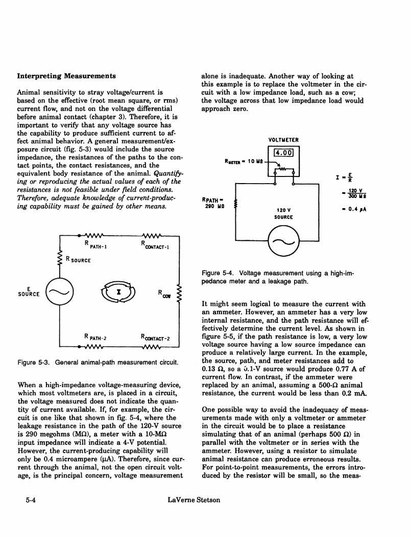
Interpreting Measurements
Animal sensitivity to stray voltage/current is based on the effective (root mean square, or rms) current flow, and not on the voltage differential before animal contact (chapter 3). Therefore, it is important to verify that any voltage source has the capability to produce sufficient current to af- fect animal behavior. A general measurement/ex- posure circuit (fig. 5-3) would include the source impedance, the resistances of the paths to the con- tact points, the contact resistances, and the equivalent body resistance of the animal. Quantify- ing or reproducing the actual values of each of the resistances is not feasible under field conditions. Therefore, adequate knowledge of current-produc- ing capability must be gained by other means.
SOURCE
E SOURCE
JVWV^ -JVSAAA-
PATH-l CONTACT-1
COW
PATH-2
•-VWSAr- »^CONTACT-Z
-WWS/—-
Figure 5-3. General animal-path nneasurement circuit.
When a high-impedance voltage-measuring device, which most voltmeters are, is placed in a circuit, the voltage measured does not indicate the quan- tity of current available. If, for example, the cir- cuit is one like that shown in fig. 5-4, where the leakage resistance in the path of the 120-V source is 290 megohms (MQ), a meter with a 10-Mß input impedance will indicate a 4-V potential. However, the current-producing capability will only be 0.4 microampere (|iA). Therefore, since cur- rent through the animal, not the open circuit volt- age, is the principal concern, voltage measurement
alone is inadequate. Another way of looking at this example is to replace the voltmeter in the cir- cuit with a low impedance load, such as a cow; the voltage across that low impedance load would approach zero.
VOLTMETER
RMCTEH- 10 MO
RPATH- 290 MO
120 V SOURCE
_ 120 V 300Ma
0.4 ^A
Figure 5-4. Voltage measurement using a high-im- pedance meter and a leakage path.
It might seem logical to measure the current with an ammeter. However, an ammeter has a very low internal resistance, and the path resistance will ef- fectively determine the current level. As shown in figure 5-5, if the path resistance is low, a very low voltage source having a low source impedance can produce a relatively large current. In the example, the source, path, and meter resistances add to 0.13 fí, so a Û.1-V source would produce 0.77 A of current flow. In contrast, if the ammeter were replaced by an animal, assuming a 500-fí animal resistance, the current would be less than 0.2 mA.
One possible way to avoid the inadequacy of meas- urements made with only a voltmeter or ammeter in the circuit would be to place a resistance simulating that of an animal (perhaps 500 CD in parallel with the voltmeter or in series with the ammeter. However, using a resistor to simulate animal resistance can produce erroneous results. For point-to-point measurements, the errors intro- duced by the resistor will be small, so the meas-
5-4 LaVeme Stetson

AMMETER
RMETOI- 0.030
I-i
RPATH- 0.1 fl
0.1 V SOURCE
_ 0.1 V 0.13 0
- 0.77 A
Figure 5-5. Current measurement with an ammeter and a low-impedance-source path.
urements will give a reasonable indication of the severity of a stray voltage/current problem. The er- rors will be due to differences in contact resistan- ces and variability in body resistance of cows. The metal-to-metal contact resistances of the measure- ment circuit will likely be very different from cow contact resistances, e.g., the contact resistance of dry fur touching a metal stanchion is significantly greater than the resistance of metal-to-metal con- tact. In addition, the body resistance of cows varies among animals and according to points of contact, e.g., mouth to four hooves or front leg to rear hock. Estimates of body resistance for cows can be found in chapter 3. Even under experimen- tal conditions it is difficult to separate contact resistances from body resistance; after all, no measurements can be made without some form of contact. For evaluation purposes, it is often suffi- cient to consider the worst case resistance, i.e., the lowest resistance likely to be encountered. We consider 500 Q, for the sum of contact and body resistances to be a very conservative estimate of the worst case, or minimum, resistance that is likely to be encountered.
For point-to-reference ground measurements, the errors introduced are serious, and a simulated animal resistance should not be used. When a 500- Q, resistance is placed across the voltmeter, the resistance to earth of the reference electrode can
affect the measured value. For example, figure 5-6 shows that if a voltage source of 2.5 V with no path resistance and 500-ß resistance to earth is measured with a high impedance meter, placing 500 Í1 across the meter will reduce the voltage reading from 2.5 V to 1.25 V. In this example the voltmeter is measuring the voltage across only a component of a voltage divider (made up of the resistor and the resistance to earth of the refer- ence electrode). Since the animal will never be in series in the reference electrode circuit, this is not a valid measurement of a voltage or current source for the animal.
VOLTMETER
RMETEH- 10 Mû
RsHUNT- 500Û
2.5 V
SOURCE
"ELECTRODE" 500 0
Figure 5-6. Voltage measurement with shunt and a high-impedance reference ground showing voltage divider effect.
A combination of readings will provide the most meaningful information when a high impedance (greater than 1 MÍ2) voltmeter is used for stray voltage investigations. Generally the combination consists of two voltage measurements: 1) with no loading and 2) with a (1- to 10-Kohm) loading resistor across the voltmeter. For both measure- ments, good contact between meter leads and con- tact surfaces must be made. Using a 10-K loading resistor across the meter gives a suflBcient indica- tion of whether or not the source truly has a high
Detection and Measurement 5-5

impedance (low current capability). We consider that the 10-K resistance is large enough that the resistance of a reference electrode will have little effect on point-to-reference ground measurements or, when carefully done, on point-to-point measure- ments.
Stray-voltage I current problems exist only if the fol- lowing two conditions are met: 1) A voltage can be measured between two animal contact points and 2) the current that flows, when a resistance equivalent to that of an animal and its contact resistances is connected across the contact points, is greater than the threshold current needed to elicit a response from an animal.
Instruments
When making measurements, instrument charac- teristics and monitoring points are significant con- siderations. The instrument must be able to separate alternating current (ac) and direct cur- rent (dc) and must have a resolution of 0.1 V. If the instrument is to be operated in place over ex- tended periods, it must be able to withstand the harsh physical environment of the farm (wet, dirty, corrosive) or be protected from it. The instru- ments must also be protected against electrical ex- tremes, such as faults or lightning.
As shown in figure 5-2, one suggested location for a monitoring device is from the neutral bar of the service entrance panel to a reference electrode away from the building. For a more visible loca- tion, the device may be placed between metallic equipment known to be bonded to the service panel and the reference electrode if careful con- sideration is given to path resistances. Alterna- tively, if the instrument, connecting leads, and contact points can be protected from damage, vol- tages can be monitored in a point-to-point area of concern.
Measurements
Several types of measurements may be necessary to identify and confirm the presence of a problem
voltage on a dairy facility. Measuring instruments may include an indicating portable voltmeter, recording voltmeter, oscilloscope, clamp-on am- meter, recording ammeter, ground resistance tester, and insulation tester. Each of these instru- ments and its applications are discussed. Some measurement procedures can be hazardous and should only be performed by qualified personnel with adequate training in safety procedures. Also, regardless of the complexity of a stray voltage/cur- rent problem, measurements made between ran- dom points without an understanding of the intricacies of the problem and the meaning of the electrical quantities measured, or without knowledge of the characteristics of the instruments used, are of little value. Please give careful con- sideration to the warning at the beginning of this handbook.
Voltage
One of the most common variables measured in stray voltage investigations is voltage. Grenerally voltage is measured with a voltmeter, e.g., an analog volt-ohm meter (VOM), a digital multi- meter (DMM), or an oscilloscope. For use in stray voltage investigations, a voltmeter must meet three major requirements: 1) It must be able to separate alternating current (ac) and direct cur- rent (dc) voltages, 2) it must have a minimum volt- age resolution of 0.1 V, and 3) it must have an impedance of at least 5,000 fl/V.
If the meter reads on the ac scale when connected to a flashlight battery, it does not separate ac and dc (fig. 5-7). A capacitor of at least 5 microfarads (^iF) with a voltage rating of at least 50 V (use 200 V if it is possible that an inexperienced per- son might try to measure a 120-V circuit) must be placed in series with one lead of the meter for reasonable ac readings (fig. 5-8). A meter with an input impedance of less than 5,000 iW may imdu- ly load the circuit it measures. Most quality volt- age instruments have a high internal-input impedance (resistance). Such voltmeters charac- teristically produce very little load on the circuit or device where the voltage is being measured and, thereby, have a minimal effect on the circuit. A high internal resistance means that only an ex- tremely small current is needed to measure a
5-6 LaVeme Stetson
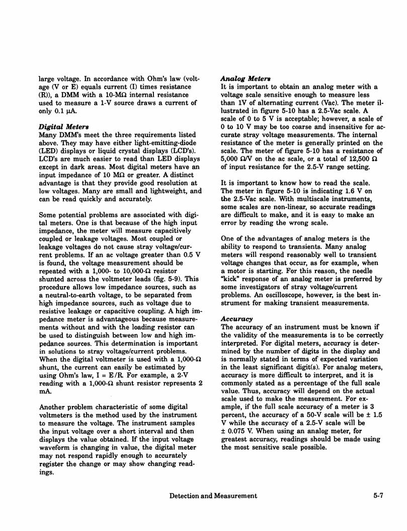
large voltage. In accordance with Ohm's law (volt- age (V or E) equals current (I) times resistance (R)), a DMM with a 10-MQ internal resistance used to measure a 1-V source draws a current of only 0.1 ^A.
Digital Meters Many DMRTs meet the three requirements listed above. They may have either light-emitting-diode (LED) displays or liquid crystal displays (LCD's). LCD's are much easier to read than LED displays except in dark areas. Most digital meters have an input impedance of 10 MÍ2 or greater. A distinct advantage is that they provide good resolution at low voltages. Many are small and lightweight, and can be read quickly and accurately.
Some potential problems are associated with digi- tal meters. One is that because of the high input impedance, the meter will measure capacitively coupled or leakage voltages. Most coupled or leakage voltages do not cause stray voltage/cur- rent problems. If an ac voltage greater than 0.5 V is foimd, the voltage measurement should be repeated with a 1,000- to 10,000-Q resistor shunted across the voltmeter leads (fig. 5-9). This procedure allows low impedance sources, such as a neutral-to-earth voltage, to be separated from high impedance sources, such as voltage due to resistive leakage or capacitive coupling. A high im- pedance meter is advantageous because measure- ments without and with the loading resistor can be used to distinguish between low and high im- pedance sources. This determination is important in solutions to stray voltage/current problems. When the digital voltmeter is used with a 1,000-Í2 shunt, the current can easily be estimated by using Ohm's law, I = E/R For example, a 2-V reading with a 1,000-Q shunt resistor represents 2 mA.
Another problem characteristic of some digital voltmeters is the method used by the instrument to measure the voltage. The instrument samples the input voltage over a short interval and then displays the value obtained. If the input voltage waveform is changing in value, the digital meter may not respond rapidly enough to accurately register the change or may show changing read- ings.
Analog Meters It is important to obtain an analog meter with a voltage scale sensitive enough to measure less than IV of alternating current (Vac). The meter il- lustrated in figure 5-10 has a 2.5-Vac scale. A scale of 0 to 5 V is acceptable; however, a scale of 0 to 10 V may be too coarse and insensitive for ac- curate stray voltage measurements. The internal resistance of the meter is generally printed on the scale. The meter of figure 5-10 has a resistance of 5,000 ON on the ac scale, or a total of 12,500 ß of input resistance for the 2.5-V range setting.
It is important to know how to read the scale. The meter in figure 5-10 is indicating 1.6 V on the 2.5-Vac scale. With multiscale instruments, some scales are non-linear, so accurate readings are difficult to make, and it is easy to make an error by reading the wrong scale.
One of the advantages of analog meters is the ability to respond to transients. Many analog meters will respond reasonably well to transient voltage changes that occur, as for example, when a motor is starting. For this reason, the needle "kick" response of an analog meter is preferred by some investigators of stray voltage/current problems. An oscilloscope, however, is the best in- strument for making transient measurements.
Accuracy The accuracy of an instrument must be known if the validity of the measurements is to be correctly interpreted. For digital meters, accuracy is deter- mined by the number of digits in the display and is normally stated in terms of expected variation in the least significant digit(s). For analog meters, accuracy is more difficult to interpret, and it is commonly stated as a percentage of the fiill scale value. Thus, accuracy will depend on the actual scale used to make the measurement. For ex- ample, if the full scale accuracy of a meter is 3 percent, the accuracy of a 50-V scale will be ± 1.5 V while the accuracy of a 2.5-V scale will be ± 0.075 V. When using an analog meter, for greatest accuracy, readings should be made using the most sensitive scale possible.
Detection and Measurement 5-7

MULTIMETER MULTIMETER
O 0303
AC 20 V Q 9
CHECKIN« THE MCTEI FOR DC REAOINO ON AC SCALE
FUSHLIGHT BAHERY
Figure 5-7. Checking a meter for the ability to separate ac and dc voltages.
0 0303 Qo03 o3
AC 20 V CP <P
1.000 - 10.000 Jl III parclM
with T«st lMd8
v^A^^
Figure 5-9. Voltage measurement using a shunt resis- tor to test tlie current-producing capacity of a source voltage.
MULTIMETER
CO 0303 0x0 O
AC 20 V Q Q
5 - lOüf copoeltor roUd 50 V ùT qrêoiér -p
Figure 5-8. Use of blocking capacitor when meter does not separate ac and do voltages.
Figure 5-10. An analog volt-ohm-milliammeter. The meter indicates 1.6 V on the 2.5-Vac scale.
5-8 LaVeme Stetson

Voltage Measuring Techniques Voltmeter test probes must make good electrical contact with the two points between which a volt- age may appear. Often the existence or absence of a stray voltage/current problem cannot be resolved by one or several individual voltage measure- ments. One solution is to attach the leads of a portable voltmeter between the critical points of concern and have an observer record numerous readings over a period of time. Several voltmeters can be used with an observer for each. Some meters have a memory feature which will save maximum and minimum readings until they are retrieved and the meters reset.
Recording Meters Another means for determining the existence or absence of a problematic voltage is to use a record- ing voltmeter. A recording voltmeter should have the same characteristics as an indicating voltmeter, i.e., high impedance, separation of ac and dc voltages, and capability to resolve a mini- mum of 0.1 V. Transient response time could also be important if rapid voltage variations occur. In addition, it is desirable that a recording meter be able to record voltage between two or more points (multiple channels).
Multiple-channel voltmeter recorders are available in both continuous (analog) and digital types. The continuous types have a specific voltage range, while the digital recorders are autoranging. Each may have an advantage, depending on the in- tended use and the knowledge level of the user. Recording voltmeters can gather voltage informa- tion for several days or weeks. This capability is especially important when problem voltages are suspected but not foimd at the time of single volt- age measurements, as some problems occur infre- quently. Recording voltmeters can also be used to record test results as specific loads are operated or other tests are conducted.
Oscilloscopes A portable oscilloscope can be used to measure peak voltages and display actual voltage waveforms. The oscilloscope may be used alone or in parallel with an indicating or recording voltmeter to detect transient voltages. It should be noted that most VOM's and DMM's are calibrated
to indicate the effective value of a sine wave of the voltage/current (by rms or measurement averaging methods) and not the peak-to-peak value. Peak-to-peak values measured using an os- cilloscope can be converted to rms values by multi- plying by 0.707 or average values by multiplying by 0.636. The oscilloscope allows the simultaneous measurement of both ac and dc components of a waveform. It will reveal whether a dc source is pure dc or has been rectified from ac. It will indicate whether an ac source is 60 hertz or has other fi^equency components. Such in- formation can provide valuable clues as to where to look for the source of the voltage. The oscillo- scope can also reveal if the current producing the voltage changes phase as specific loads are operated. The oscilloscope should be battery operated or operable in a differential mode (two in- puts balanced to ground). Most line-voltage- operated oscilloscopes have one terminal connected to the equipment grounding conductor; thus, this terminal is normally at the neutral-to-earth volt- age. This connection makes it difficult to properly measure the voltage between two animal contact points.
Current
In stray voltage investigations, it may be neces- sary to make several current measurements. These measurements commonly include current producing capability of circuits involving animal or human contact points, normal load current, and fault or leakage currents. The current require- ments of motors, lights, and other equipment can be measured to determine whether the equipment is operating properly. The current in an equip- ment grounding conductor can be measured to check for fault or leakage currents. The total cur- rent requirements of a building or set of buildings may be measured to determine adequacy of the electrical service. To help diagnose neutral voltage drop, measuring the neutral current during periods of peak power usage is useful. Neutral cur- rent measurements also aid in determining whether or not the electric loads are balanced or when imbalance occurs.
For many current measurements, clamp-on-type ammeters or recording ammeters are used. Some
Detection and Measurement 5-9

types of ammeters require opening of the circuit to connect the ammeter in series with the circuit or to install a current transformer. Either such in- stallation can be hazardous. Ammeters used in series circuits are accurate but have a fixed cur- rent range. There are many styles and jaw types of clamp-on ammeters to choose from. Some digi- tal clamp-on ammeters or DMM accessory clamp- ons have autoranging from 1 to 999 A and are easily and accurately read. They may also have a locking function to measure peak amperages from rapidly changing loads such as motor-starting cur- rent. Clamp-on ammeters are generally not ac- curate at levels below 1 A.
Detection of currents less than 1 A in grounding conductors can be of significant value in locating sources of stray voltage. An AC AMP CLIP (Wm. H. Swain Co., Sarasota, FL), which is a clamp-on ammeter and has ranges from 1 mA to 20 A full scale, can be used for quick measurements of low currents.
For safety reasons, use of clamp-on ammeters is preferred. Extreme care must be taken when maneuvering the clamp in crowded electrical enclosures. To use series ammeters, the circuit must be opened, and doing so can result in dangerous voltages appearing across the open cir- cuit.
During an investigation it may be desirable to determine the ability of the stray voltage source to deliver current. The ac milliammeter range of a multimeter can be used for this measurement. To avoid damaging the meter, it is important to begin with the highest value scale. The meter can then be switched to successively lower scales until a reading is obtained. The ammeter has a very low input resistance; therefore, a resistor must be placed in series with one lead, as illustrated in fig- ure 5-11. A 500-Í2 resistor is shown to ap- proximate the minimum contact and body resistance of an animal. An animal contacting the two measuring points can therefore be assumed to conduct about the same level of current.
MILLIAMMETER
p 0303 C0o03o3
AC 20 V CP <P
COPPER PUTE ON lET CONCRETE FLOOR OR EARTH
STEEL PIPE
I o-ot
^^ ^ O 500 0
Figure 5-11. A current reading with a 500-ohm resistor in series to approximate the minimum contact and body resistance of an animal.
Resistance
Resistance is the opposition offered by a body or substance to the passage through it of a steady electric current. Impedance is the apparent opposi- tion in an electrical circuit to the flow of an alter- nating or time-varying electrical current. If the opposition to current flow for a given body or sub- stance does not vary when the flow of current varies, resistance is equivalent to impedance. Under most conditions, little error is introduced by assuming that all loads are resistive. However, it is important to consider impedances, including phase angles, when dealing with motors and load balancing. Measuring resistance is important be- cause for any given voltage, resistance helps deter- mine the path and magnitude of current flow.
Measurement of Resistance VOM's or DMMs are often used to measure the resistance between two points. The measured value may at times be in error, as there is some- times a small dc voltage between the two points being measured. Most instruments to measure resistance utilize dc currents, and any extraneous
5-10 LaVeme Stetson

de signal will alter readings. It is always a good practice to measure ac and dc voltages between the two points of interest before measuring resis- tance. If only a low (0.5 V) dc voltage is present, two resistance measurements should be made, one with the test leads reversed, and the two readings averaged to yield a good approximation of the ac- tual resistance. If an ac or a higher (>0,5 V) dc voltage is present, direct readings of resistance are impossible and should not be attempted.
Equipment Grounding
If voltages to earth appear on equipment or along an equipment grounding conductor, it is often necessary to track down the reason for the volt- age. If there is a bad (high resistance) connection in the equipment grounding circuit, even low leakage currents can produce measurable voltages on supposedly grounded equipment. These bad con- nections often occur where flexible or rigid condxiit or metallic raceways are used for the equipment groxmding conductor. The fastening nuts, screws, etc., may not cut through the paint on the equip- ment, and may loosen, rust, or otherwise develop a high resistance joint. The testing technique is to measure the voltage across each joint or connec- tion. If necessary, a low voltage transformer providing several amperes of current can be con- nected to force a current from various points on the grounding system to the jimction of the groxmding conductor and neutral at the service entrance. For safety reasons, the transformer out- put voltage should be less than 25 V This in- creased current will allow easier detection of bad connections. The apparatus may need to be moved or shaken while the current magnitude is ob- served to find intermittent poor grounding connec- tions.
Grounding Electrodes Measuring the resistance to earth of ground rods or structures such as stanchions can add impor- tant information concerning the relative effective- ness of various ground paths. These measurements can be used to determine whether the on-farm and service grounds are adequate or need to be supplemented. The relative impedance values of the on-farm groimding system and the
utility grounding systems may also be of impor- tance.
The groimding system on a farm usually consists of several electrodes. Each building should have a grounding electrode as part of the electrical ser- vice. Grounding and bonding of metal structures such as stanchions, metal water pipes, buildings, and equipment in contact with the earth adds ad- ditional equivalent electrodes.
The resistance to earth of an electrode can be measured by the three-point or the three-terminal fall-of-potential method, as shown in figure 5-12. A current is injected into the earth from a low-volt- age, high-current source, and the voltage between the potential probe and the groimd rod is measured. The resistance is determined from Ohm's Law, R = V/I, where I is constant and V is measured. The placement of the two auxiliary electrodes P2 and C2 is important. The distance from Ci to P2 should be at least six times the depth of the grounding electrode Ci. The distance Ci to C2 should be at least 10 times the depth of Ci. These distances minimize the effects of the fields from each of the electrodes. A triangulation method is used to determine resistance to earth (Fink and Beaty 1971). The resistance can also be registered directly by earth resistance testers.
power supply
earth electrode
to be tested
Figure 5-12. Test setup for measuring grounding electrode resistance by the fall-of-potential method. V » voltmeter, A = ammeter, C^ = electrode to be tested, C2 = current injection electrode, and Pg = voltage measurement electrode.
Detection and Measurement 5-11
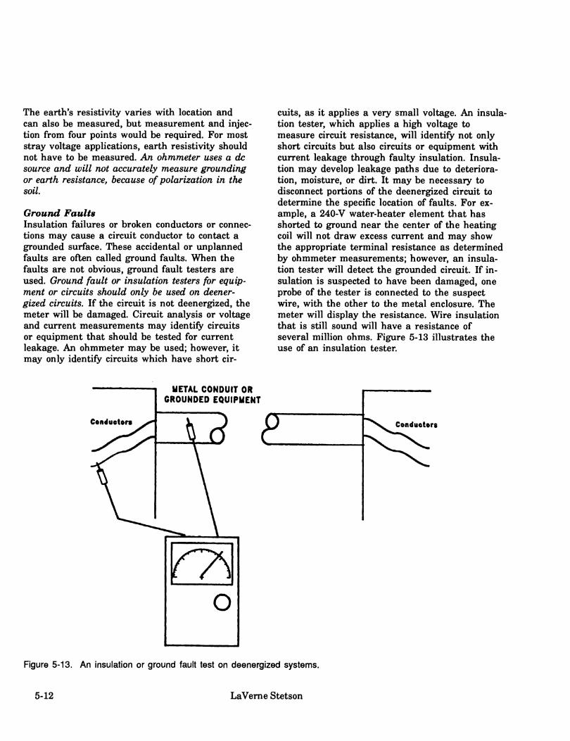
The earth's resistivity varies with location and can also be measured, but measurement and injec- tion from four points would be required. For most stray voltage applications, earth resistivity should not have to be measured. An ohmmeter uses a dc source and will not accurately measure grounding or earth resistance, because of polarization in the soil
Ground Faults Insulation failures or broken conductors or connec- tions may cause a circuit conductor to contact a grounded surface. These accidental or implanned faults are often called ground faults. When the faults are not obvious, groimd fault testers are used. Ground fault or insulation testers for equip- ment or circuits should only be used on deener- gized circuits. If the circuit is not deenergized, the meter will be damaged. Circuit analysis or voltage and current measurements may identify circuits or equipment that should be tested for current leakage. An ohmmeter may be used; however, it may only identify circuits which have short cir-
cuits, as it applies a very small voltage. An insula- tion tester, which applies a high voltage to measure circuit resistance, will identify not only short circuits but also circuits or equipment with current leakage through faulty insulation. Insula- tion may develop leakage paths due to deteriora- tion, moisture, or dirt. It may be necessary to disconnect portions of the deenergized circuit to determine the specific location of faults. For ex- ample, a 240-V water-heater element that has shorted to ground near the center of the heating coil will not draw excess current and may show the appropriate terminal resistance as determined by ohmmeter measurements; however, an insula- tion tester will detect the grounded circuit. If in- sulation is suspected to have been damaged, one probe of the tester is connected to the suspect wire, with the other to the metal enclosure. The meter will display the resistance. Wire insulation that is still sound will have a resistance of several million ohms. Figure 5-13 illustrates the use of an insulation tester.
METAL CONDUIT OR GROUNDED EQUIPMENT
Contfuotors
Figure 5-13. An insulation or ground fault test on deenergized systems.
5-12 LaVeme Stetson
Conductor insulation can be damaged during in- stallation or by vibration, animals, or even lightn- ing. Equipment such as motors, transformers, and controllers can also be tested for ground faults. Special care must be taken when testing circuits which normally supply power to electronic equip- ment; the voltages generated by an insulation tester may damage the equipment. It may be neces- sary to remove a neutral connection for some tests because of the bond between the neutral and the equipment grounding conductors.
Investigation Procedures
The investigation should begin by gathering and recording evidence to indicate that a stray volt- age/current problem really exists on the farm. In- formation requested in the following questionnaire should be obtained with help from the farm operator:
1. Names, addresses, titles, telephone numbers of persons present, and location and date of the stray voltage investigation.
2. Names, addresses, professions, and telephone numbers of others who may have previously made an investigation and their remarks.
3. When did farmer first suspect there was a voltage problem and why?
4. Do some or all animals react?
5. Where are the reactions observed and what kinds of reactions are they?
6. Is reaction continuous or periodic?
7. At what times of the day is problem most noticeable?
8. Is problem more noticeable in wet or dry condi- tions, or is it seasonal?
9. What changes have been made in farm electri- cal systems, operators, or animal handling procedures?
10. Does operator receive shocks or see sparks?
11. Have both voltage and current measurements been taken? Where? When? By whom?
12. What recommendations were made as result of previous investigations, and what actions were taken?
13. Sketch the farm layout showing locations of all distribution lines, transformers, services to buildings, and grounding electrodes. Note: Service voltages, single- or three-phase, delta or wye, sizes of equipment.
14. Have neighbors had electrical problems of any kind? If they have, what details are available?
15. Has lightning struck in the vicinity of the farm? Where? When?
16. Note the overall condition of the wiring and electrical equipment on the farm. Look for un- suitable equipment, lack of maintenance, leakage paths, corrosion, and type and extent of neutral and equipment grounding conduc- tors and grounding of main and building ser- vice-entrance equipment.
17. Note persons and organizations that have made wiring installations on the farm (electri- cal contractor, equipment installer, farmer, other).
18. What information or assistance has been ob- tained from the electric power supplier, electricians, or equipment suppliers?
Visual inspection should discern the farmstead's electrical system layout, adherence to electrical codes, obviously imsafe equipment, or wiring condi- tions and maintenance needs. However, it must be recognized that visual inspection alone cannot con- firm that existing, electrical safety hazards are in- deed potential sources of stray voltage/current problems.
Detection and Measurement 5-13

Farm Secondary Systems
Electrical measurements are necessary to show whether any source or sources of voltage capable of being contacted by the animals exist at the site. Use of the detection methods described ear- lier in this chapter can reveal the existence of problem level voltages capable of supplying suffi- cient current to be of concern. When such voltages are detected, specific source identification and mitigation will be required, as described in other sections of this handbook. Installation of a monitoring system and instruction of the farmer/operator in use of the monitoring system may be needed to detect intermittent problems.
Farm Equipment Suppliers Farmstead electrical equipment is often installed and serviced by equipment suppliers. These sup- pliers have a special knowledge about the operat- ing characteristics of their equipment auid may provide valuable assistance in solving stray volt- age/current problems.
Electricians and Installers Electricians who are knowledgeable of prevailing electrical codes, qualified to do farmstead wiring, experienced with measurement instruments, and trained or experienced in stray voltage investiga- tion are needed to deal with stray voltage/current problems. They should be called upon to do the testing, and they should also be able to identify specific sources of problems, make necessary on- farm repairs and changes, and work with utility personnel if off-farm sources are identified.
The impedance/resistance bridge and insulation testing equipment would be used by electricians to verify the adequacy of grounding electrodes, test equipment grounding, locate neutral-to-ground in- terconnections and ground faults, and test for in- sulation leakage or capacitively coupled paths. Multichannel recording (ac) voltmeters connected to points of concern can be particularly helpful in detecting recurring or random electrical events which may not occur at the time of controlled test- ing.
Electrical Professionals Electrical professionals (consultants and utility en- gineers), generally engineers dealing in electrical power, will play a role in 1) the training of others involved in stray voltage investigations, 2) source identification in particularly complex situations, 3) specific quantification of voltage sources, 4) assess- ment of electrical system characteristics, and 5) recommendation of mitigation techniques. These persons must possess a complete understanding of the electrical circuits both on and off the farm, animal sensitivity, and measurement equipment and techniques.
Engineers actively involved in stray voltage field investigations will need not only the equipment commonly used by electricians and others but also, at times, more advanced tools, such as an os- cilloscope, recorders, and disturbance monitors. The oscilloscope can be used for study of both phase relationships and waveforms, which cannot be done with standard voltmeters.
Primary Distribution Systems
Should a voltage investigation show the need for making changes to the distribution transformer or distribution system leading to the farmstead, the changes must be made by utility personnel trained and equipped to deal with high voltage systems. Safety and legal considerations dictate that other persons should not approach or attempt to modify the utility system. Utility personnel can be readily grouped into three categories on the basis of their levels of electrical expertise.
Power Use Advisers Power use advisers are nonelectrical professionals or customer service personnel who would likely be mostly involved in initial on-farm discussions.
Line Maintenance Crews Line maintenance crews are knowledgeable about primary system configurations and may be trained to interact with and support persons doing on- farm work and can investigate the location of primary system sources such as faulty connectors. However, they are generally not qualified, and may not be authorized, to do on-farm electrical in- spection or work.
5-14 LaVeme Stetson

Power Utility Engineers Utility engineers are professionals who are knowledgeable about electrical circuits and electri- cal systems. A cooperative effort of the utility en- gineer and the on-farm investigator is often necessary.
Use of the standard electrical tools (voltmeter, am- meter, oscilloscope, earth resistance bridge, and in- sulation tester) and procedures can help the investigator determine whether a possible source is on the primary distribution side or on the farm secondary system. It may be necessary for the utility personnel to temporarily disconnect the farm secondary neutral from the primary distribu- tion neutral to remove interactions between pos- sible on-farm and off-farm problems. Taking these actions may enable trained utility personnel to make recommendations on mitigation. Most oflen line personnel with skills and access to sophisti- cated electrical equipment will be working imder the supervision of a utility engineer.
Additional Sources of Information
For additional information on investigative proce- dures, see Surbrook and Reese (1981), Gustafson (1983c), Stetson and Bodman (1985), and Cloud et al. (1987).
Detection and Measurement 5-15
6. Recommendations for Research Lloyd B. Craine, editor
Summary
Research is recommended to broaden our data base on the physiological effects of stray vol- tages/currents on farm animals. Research is also recommended to determine how farm animals will be or are affected by the following: 1) anticipated changes in the Nation's electrical power system, 2) transient voltages and currents, and 3) direct cur- rent voltages and direct currents. Finally, the recommendations are made that all devices and methods for mitigating stray voltages/currents be independently evaluated by appropriate experts and the results made available to the community concerned with stray voltage/current problems.
Recommendations for Research 6-1

Introduction
Research on stray voltage/current/animal effects due to the use of electrical power on farms has been conducted at a number of institutions in several different countries over the past 20 years. The breadth of the research is apparent from a review of chapter 8, "Bibliography." The essential findings of this research are summarized in this handbook. The problems that can arise from the use of electricity on farms, and methods for mitigating stray voltage/current problems that may affect animal productivity, health, or reproduc- tion are well known. Thus, once the presence of such a problem has been confirmed and the electri- cal source identified, application of an appropriate mitigation method will generally solve the prob- lem.
However, there are several areas where possible problems requiring careful examination may still exist, and where definitive research to better describe the problem and provide solutions is recommended. The areas are discussed below with a brief backgroxmd, sense of difficulty, and recom- mendation. The list is not in order of priority.
Physiological Effects
The basic physiological mechanisms by which electrical energy affects animals are well docu- mented. The effects of electrical energy on neural electrical/chemical interactions in animals are com- plex, and examining those effects is beyond the scope of stray voltage specialists. This handbook discusses the physiological and behavioral effects of electrical current with respect to dairy animals. Further research is needed to gain information on how animals perceive and interpret current flow. Having this information would allow us to better quantify costs and effects of stray voltage/current problems and of mitigation techniques.
Recommendation Research comparing the physiological basis of responses to electric shock in dairy cattle with other species would allow data collected for other species to be used to predict responses of dairy cat- tle more accurately than is presently possible. In addition, establishing the variability in sensitivity and response to current for a large number of dairy animals would allow construction of a more precise model of responses. This model could then be used to more accurately evaluate the most cost- effective method for improving herd performance.
Power Systems
The U.S. electrical power system is a huge net- work and is based on a specific transmission, dis- tribution, and utilization philosophy. When consumer equipment consisted primarily of lights, motors, and tube-type electronic equipment, and electrical loads were relatively small, neutral-to- earth voltages and transients were not great problems, due to the lower neutral currents and the tolerance of the equipment. With increasing use of low-signal-level solid-state computers and microprocessors, increasing electrification and auto- mation of farms, and increased loads on distribu- tion lines, the issue of power quality and tolerable neutral-to-earth voltage is becoming increasingly important. It will become necessary in the future to more clearly specify the power characteristics that the utility is to provide at the delivery point, the limits to which a consumer's type of usage can be allowed to affect other customers and the utility, and who is to monitor and require confor- mance to the specifications. The ramifications of meeting these needs are that difficult economic, technical, and legal problems will arise and will have to be solved.
The characteristics of electrical power systems usually found on farms, especially dairy farms, and the ways in which stray voltages can occur in animal contact areas are discussed in this hand- book. But additional research on farm power sys- tems is needed to improve our understanding of stray voltage/current problems.
6-2 Lloyd B. Craine

Load Growth Transients
The increase in neutral currents and leakage or uncleared fault currents to earth due to electrical load growth on a farm or along a distribution line can lead to an increase in the neutral-to-earth volt- age.
Recommendation Research is needed to establish reasonable limits for neutral-to-earth voltages on primary distribu- tion and secondary service lines. Because these vol- tages can affect a wide variety of power consumers, the research should eventually result in the modification and expansion of both the Na- tional Electrical Safety Code (NESC), applicable to the power distribution system, and the National Electrical Code (NEC), applicable to the consumers' local service system. Because of the usual interconnection of these two systems by the common neutral connection and common ground rod at the customers' distribution transformer, these two codes will have to be coordinated. Neutral-to-earth voltage problems due to load growth will need to be exhaustively studied to fore- stall the development of additional problems.
Power Quality
With the increased use of sophisticated electri- cal/electronic control and recording equipment by farm operators and other consumers, the quality of the power delivered to the consumer needs to be better understood and standardized. Such condi- tions as power surges, low voltages (brownouts), and transients (voltage or current impulses of short duration) all can harm dairy equipment and lead to stray voltage/current problems.
Power utilities generally have not addressed the need to maintain good power quality for certain equipment; so thus far, the consumers have had to identify, select, purchase, and install the proper equipment to modify, as needed, the basic power delivered by the utility.
Recommendation Power quality problems and the effects on farm operations and animals need to be better under- stood through continuing research.
Transients are voltage or current impulses of short duration that occur either regularly or ir- regularly. Some transients can be associated with the operation of a particular device, such as a motor starting, or a switching relay, and can there- fore be caused to reoccur when desired. Other transients cannot be associated with a single operation but, rather, with a complex system in operation. Still other transients appear to be ran- dom events that can be neither traced nor repeated when desired. Transients may differ in amplitude, waveform, and time span. The time in- tervals between transients often vary, and trains of various types of transients may be observed. Electrified fences and cow trainers are examples of long-used equipment capable of producing tran- sients on farms.
Dominant, repetitive transients that can be traced to particular equipment can often be reduced or eliminated by modification of the transient-produc- ing equipment. If the source and occurrence rates are unknown, and the transient waveform varies, a general-type filtering or clamping system may be needed at points where the transients affect equipment or animals. Transients may be generated on-farm or off-farm and, depending on their characteristics, may or may not be capable of eliciting an animal response.
The types of transients observed on farms have not been welldescribed, although they are likely to be similar to transients appearing on other electri- cal power systems. They arise from the same causes, high-starting in-rush currents in motors and inductors; voltages generated when current is switched off (the magnetic field collapses and ar- cing appears across contacts); intermittent faults between power conductors creating intermittent ar- cing not sufficient to open protective devices; solid- state switching devices; electrified fencers, etc. Some transients can propagate over long distances along power conductors. Transients originating on one premise may be transferred to another by a distribution-power-line connection in common.
The effect of a transient voltage superimposed on the regular power voltage (dc or ac) is to cause a
Recommendations for Research 6-3

momentary change in the waveform. When the transient causes the momentary voltage to be greater than normal, it may cause a transient cur- rent to flow in an animal. The current waveform in the animal will depend on the source im- pedance, the connecting impedances, and the animal impedance characteristics. If the transient waveform has sufficient energy (magnitude and duration), there may be an animal response. The number of joules transferred, or the I t factor (where t=time), may be used as a general measure to compare transients of various waveforms.
Difficulty The effect of various types of transients, or a Joule or I^t factor level causing duplicative respon- ses in animals, has not been established and should be determined in future research. Humans can detect high level transients (such as the electrical charges that develop while walking on rugs or sliding out of a car and that are dis- charged when metal is touched) but may not notice similarly produced lower level transients. Likewise, animals may or may not detect (show a response to) transients appearing on power sys- tems, depending on the magnitude of the tran- sients. Due to the intermittent and variable characteristics of transients (even those from a particular source may vary considerably each time they occur), it would be necessary to agree on a definable transient to use for testing animal response. The test procedure would need to 1) in- clude the variability in occurrence rate of the tran- sient and methods to detect and associate a specific animal response to the transient and 2) determine the implications of the response (whether or not the response actually harms the animals). Because transients are usually superim- posed on an existing voltage, agreement on the test voltage conditions would be needed. The animal-current waveform would be needed, not the source waveform, when testing.
Recommendation Transient-effects research is necessary to fully evaluate power system effects on animals. Surveys to establish the existence and characteristics of transients and the effects of transients on animals are needed to determine whether a full research
program is required. Both short term and long term tests would be needed to provide data on transient current effects on animals. Occasional transients may be accepted by animals, just as static discharges are accepted by people, without permanent effects. Continuing exposure to consis- tent or intermittent transients may have harmful effects if they exceed levels yet to be determined.
Power System Maintenance
Aging distribution or farm electrical systems can develop a number of problems. In addition, many older systems were installed without the knowledge developed later that reduced system problems. Power systems need to be inspected and, if necessary, brought up to modern electrical code standards. Even modern systems can develop leakage, partial fault, or other dangerous condi- tions due to the dairy environment.
Recommendation Dissemination of research results in particular case studies would be useful to inform farm per- sonnel of new, different, or unusual problems with power system maintenance.
General Recommendations on Power Sys- tems
It will be necessary for farm-type consumers to settle on realistic specifications of farm power quality in cooperation with other consumers of power. Many other consumer groups should be in- volved in this specification process.
Research is needed to determine whether a dif- ferent configuration for particular types of farm power systems is warranted — possibly, for ex- ample, secondary single-point-groxmded systems isolated from the primary neutral grovmd with groiuid fault detectors and control devices to en- sure human/animal safety.
The relationships among transmission voltages, types of distribution — both on farm and off farm — and load need to be investigated. Present cur- rent recommendations should be reviewed to deter- mine whether they need modification.
6-4 Lloyd B. Craine

There are some voltage monitoring devices using reference ground rods to indicate farm neutral/groimd-system voltages to earth. Some devices may need to be developed to monitor and perhaps control voltages/currents at key animal contact points. A review publication would be desirable to fully answer the question, What hap- pens to current once it enters the soil at a ground- ing point, and does it affect an animal near or far away from the grounding point?
Direct Current Voltages and Direct Currents
Measurements have not been properly made on enough farms to fully identify the likelihood of any direct current (dc) problems on farms.
The effect of direct current on animals from con- tact through different animal contact paths is not well known, although there is some concern that this may be an additional animal production or health problem. Preliminary research indicates that dc voltage levels equivalent to average ac levels result in similar animal responses. Direct current voltages on a farm may come from several sources. These can be separated as follows (none, or one, or more may occur on a particular farm):
Off-Farm Sources
1. Electrolysis-preventive power supplies used on pipelines or for other earth-contacting metal structures.
2. Telephone systems connected to electrical neutral/groimd systems of farms.
3. TV cable systems connected to neutral/ground systems of farms.
4. Distribution line neutral transferring dc vol- tages/currents.
On-Farm Sources
1. Galvanic (battery-like) voltage from dissimilar metals in contact with an electrolyte.
2. Systems using dc voltages/currents as part of their operating or control circuits. (These may be driven by batteries or a rectified power supplied from ac.)
Any investigation of a farm for possible stray volt- age/current problems should always include meas- urements of dc voltages. The measurements should be made with the addition to the circuit of a load similar to that of an animal's contact resis- tance plus internal resistance. The measurements may show one of several characteristics:
1. The current falls to a very low or im- measurable value under load, indicating a leakage type source.
2. The current slowly decreases with time, indicat- ing a polarizing source.
3. The current remains steady, indicating a low impedance source of relatively linear charac- teristics.
The meter measurements should include a waveform measurement by a battery operated os- cilloscope to determine whether there is a source characteristic or stored charge phenomenon. The waveform may give clues as to the source. The waveform must be large enough in magnitude and duration (joules) to elicit a response from an animal touching the two contact points.
Measurement Problems
Measurements have not been properly made on enough farms to characterize the possible dc problems on farms. Using proper measurement techniques is highly important. The different me- tals used in the instruments, in the voltage/cur- rent contacts, and the various metal structures in contact with the farm soil and soil environment all can form a galvanic couple that may be inter- preted as a real source when, in fact, a dc voltage or direct current is present only upon attachment
Recommendations for Research 6-5

of the measuring equipment. Dissimilar metals such as copper, aluminum, steel, galvanized steel, lead, and zinc may be used or be present in the damp or wet farm soil environment. Urine and manure are often present also in the farm environ- ment and can provide electrolytes. Combinations of dissimilar metals and an electrolyte can form crude batteries. For example, where corrosion is observed on a farm, electrolysis from galvanic ac- tion may be present.
Recommendations The following recommendations are made for a re- search program to determine the effects of dc vol- tages/currents on farm animals.
1. Farms should be tested for the presence of dc voltages/currents, and if they are present, their magnitude and waveform should be measured and recorded, as well as informa- tion on where and how the measurements were made. All such recorded information should be made available to the commiuiity concerned with solving stray voltage/current problems.
2. Due to the difficulty of making reliable dc measurements, measurements should be made only by persons thoroughly knowledge- able of dc measurement techniques.
3. The effects of direct currents on animals as es- tablished from farm and laboratory tests should be researched and reported. These studies should include 1) levels giving observ- able reactions, 2) long-term tests to ascertain possible effects, and/or 3) development of what are considered acceptable levels by some statistically developed process.
Electric and Magnetic Fields
The components of an electromagnetic field are electric field, magnetic field and the propagating electromagnetic field. Electromagnetic fields are capable of producing coupled or induced currents of sufficient magnitude to affect livestock. In addi-
tion, some farmers have claimed that electric and magnetic fields from high-power transmission lines have direct, deleterious effects on livestock. However, research has shown that such fields do not adversely affect animals in the open field, even when the power transmission lines are direct- ly overhead. Such research is reported in publica- tions listed in the "Bibliography." Electric and magnetic fields from radio, TV, or other transmit- ters also are not considered a problem, as field strength rapidly decreases with increasing dis- tance from the transmitter antenna.
High electric fields from electrified fences have been used on farms to confine animals to certain areas or pathways without particular concern from farmers. Magnetic fields from local power conductors are usually essentially canceled by those of other nearby conductors of the circuit and are often confined in a shielding steel conduit, so they have not been considered to be a problem.
Sensitivity of Animals
Farmers often consider their animals to be "very sensitive" to and thus affected by stray voltage/cur- rent at a distance. What the animals are sensitive to is not identified, nor is the specific response described. In fact, such sensitivity may reflect herd management problems. In the absence both of direct animal contact with a voltage source and of ionization products, the alleged sensitivity to fields at a distance and the animals' detec- tion/response mechanism are the remaining con- cerns that might be considered for definitive research.
Difficulty The feeling that their animals are "very sensitive" and respond to unmeasurable forces or minute levels may be a position that some farmers take to continue to ascribe their herd management problems to stray voltages/currents. This percep- tion may be difficult to rationally overcome with voltage/current/field strength measurements and observable animal response data.
Recommendation Until such sensitivity to fields is proven to be a problem, no research is warranted.
6-6 Lloyd B. Craine

Where Tb Obtain Additional Information
The biological effects of power frequency fields on animals were studied and reported by the Biologi- cal Effects of Power Frequency Electric and Mag- netic Fields Working Group of the Transmission and Distribution Committee of the IEEE Power Engineering Society. The reports include data showing no measurable effects of power frequency fields on animals. In addition, see Carstensen (1987).
Mitigation Equipment
Various devices for reducing the neutral-to-earth potential on an electrical consumer's premises have been developed and marketed. The primary and secondary neutrals may be disconnected (isola- tion) and the connection replaced with an arc gap device, saturable reactor, solid state switch, or other appropriate device. Or a sensing system may be used with a controlled power source to balance out the neutral-to-earth voltage at a par- ticular location. Each of these devices has par- ticular advantages or disadvantages, including effectiveness; ease of installation; maintenance; lon- gevity; safety; durability under power-system over- voltage, fault, or lightning conditions; replaceability; and cost.
No one device is best for all farm situations. Each farm problem needs to be examined carefiilly by unbiased, experienced persons who can make proper analyses and recommendations. New proposed devices need to be analyzed, tested, and proven to be effective by independent experts before being made available for widespread use.
Recommendation All mitigation systems need to be independently evaluated and the evaluations made available to the community concerned with stray voltage/cur- rent problems.
Recommendations for Research 6-7

1. Annotated Summary and Recommendations Alan M. Lefcourt, editor
Summary
Stray voltage is a small voltage (less than 10 V) measured between two points that can be simul- taneously contacted by an animal. Because animals respond to the current produced by a volt- age and not to that voltage directly, the source of the voltage must be able to produce current flows greater than the threshold current needed to elicit a response from an animal.
While some knowledge of stray voltage has ex- isted for many years, it was not vintil about 1982 that the national and worldwide nature of this phenomenon was recognized. Even when problems associated with stray voltage were recognized, early solutions were not always fully effective and/or were not always satisfactory to both farmers and power suppliers. One of the challen- ges of solving stray voltage/current problems has been in persuading everyone involved to work as a team in diagnosing and solving the problems on the basis of a rational understanding of the fac- tors involved.
Anyone who has been involved in identifying, diag- nosing, and correcting stray voltage/current problems in livestock (usually dairy) facilities recognizes the complexities involved. The problems are often very frustrating, since many, if not most, livestock farmers have little understanding of electrical distribution and farmstead wiring sys- tems. At the same time, few electrical workers un- derstand the behavioral and physiological responses of animals to small electrical currents. Furthermore, the importance of the animal- operator interaction is not generally appreciated, i.e., the reaction of farmers to animals' behavioral changes associated with stray voltages/currents may create more serious problems.
Electrical power distribution and/or farm local ser- vice systems are the ultimate sources of almost all stray voltages/currents. The most common source of stray voltage is an elevated neutral-to- earth voltage at the farm service panel. Because an elevated neutral-to-earth voltage is the most
common source of stray voltage, it is sometimes er- roneously referred to as "stray voltage."
Cows and humans are similarly sensitive to electric current, i.e., both respond similarly to com- parable current levels. However, cows are much more susceptible to stray voltages primarily be- cause the body impedances (resistances) of cows are much lower than those of humans.
The most common method for gauging responses of cows to electric current is to measure changes in behavior. The magnitude of current needed to elicit minimal behavioral responses in cows is very similar to values given for perception of cur- rent in humans. The current necessary to elicit specific behavioral responses varies from cow to cow and depends to a lesser degree on the two points of contact, e.g., mouth to four hooves or front leg to rear hock. The voltage needed to deliver these currents depends on the body im- pedance of the cow, the contact impedance be- tween the cow and the conductive structures, any impedance of the conductive structures, and the impedance of the voltage source. A very conserva- tive estimate for a worst-case total impedance is 500 ohms. A more realistic estimate of total cir- cuit impedance is 1,000 ohms.
Older recommendations for tolerable levels of cow contact voltages (0.5 - 0.7 V) were based on the lowest values of perceived current and low values for body, contact, structure, and source impedan- ces. These past recommendations need to be reviewed in light of recent research on the economic impact of electrical currents. Recent re- search indicates that current levels below 6 mA have no direct effect on production, reproduction, or animal health; furthermore, there is no evidence that hormones naturally released during milking and stress are adversely impacted by elevated current levels. Some moderate behavioral changes are seen in cows exposed to currents of between 3 and 6 mA. If exposure to such currents occurs on-farm, the behavioral changes may re- quire an additional investment of time from the dairy operator. Using the above estimates for im- pedances, these currents translate to 1.5 to 6.0 V. However, it also appears that the large majority of cows probably do not demonstrate problem be-
Annotated Summary and Recommendations 7-1
haviors until voltages are above 3.0 to 4.0 V. Direct economic effects including reductions in milk yield have been shown for a small percent- age of cows (7 percent) at cow contact voltages of 4.0 V and above.
Experiments involving long term (full lactation) ex- posures of cows have shown that cows quickly be- come acclimated both physiologically and behaviorally to constant and intermittent currents below 6 mA.
Attempts have been made to link mastitis with stray voltage. Mastitis is a fact of life in the dairy industry. Mastitis is caused by infection of the udder and not electricity. Electrical current can af- fect the incidence of mastitis only indirectly. For example, a milking machine kicked off by a cow in response to current exposure may be reat- tached without first being cleaned. It should be emphasized that factors such as mistreatment of cows, milking machine problems, disease, poor sanitation, and nutritional disorders can create problems which manifest themselves with all the symptoms that have been associated with stray voltage/current problems.
Mitigating existing stray voltage/current problems and preventing their future development demand careful consideration of the electrical sources and the characteristics of the corrective and preventive procedures or devices that might be used, includ- ing their costs. Effects of any mitigation technique on the electrical power distribution system imder normal and fault conditions must be considered. Approaches for controlling neutral-to-earth vol- tages generally fall into four categories:
♦ Voltage reduction by mitigation of the source (e.g., by removing bad neutral connections and faulty loads, improving or correcting wiring and grounding, and load balancing).
♦ Active suppression of the voltage by a nulling device.
♦ Gradient control by use of equipotential planes and transition zones to maintain the animals' step and touch potentials at accept- able levels.
♦ Isolation of a portion of the grounding or groimded neutral system from the animals.
Equipment and procedures to detect stray vol- tages must be matched to the level of electrical ex- pertise of the investigator and the complexity of the problem. By careful selection and use, stand- ard electrical instruments are adequate for most types of measurements required for stray voltage investigations. One fundamental principle that must be kept in mind during investigations is that animals respond to the actual current pass- ing through their bodies and not to the voltage dif- ferential before animal contact. Therefore, it is important to verify that any voltage source has a current-producing capability sufficient to affect an animal. Farmers with sufficient motivation may want to attempt to test for the presence of stray voltage/current problems by measuring the vol- tages between possible points of contact or be- tween points of contact and a reference electrode driven into the earth. Techniques for making such measurements are outlined in chapter 5, "Detec- tion and Measurement." The measurements should be interpreted by professionals skilled in stray voltage/current problems and capable of making mitigation recommendations.
We recommend that new facilities for housing and handling animals incorporate an equipotential plane which is carefully bonded to the electrical neutral/ground system. We also recommend that all comprehensive reviews of farm management procedures include a brief questionnaire concern- ing stray voltage (see questionnaire in chapter 5) and that neutral-to-earth voltages be measured as part of each review.
Based on the results of numerous controlled re- search experiments, the following are recom- mended. Neutral-to-earth voltages in excess of 4 V should be mitigated regardless of the existence of an identified stray voltage/current problem. Similarly, contact voltages in excess of 2 to 4 V should be mitigated. Reducing contact voltages to below 0.5 to 1.0 V is unwarranted. Reducing neutral-to-earth voltages to below 1.0 V is also xm- warranted, based on our knowledge of relation- ships between neutral-to-earth voltages and contact voltages as well as field measurements of
7-2 Alan M. Lefcourt

these relationships. It may be advantageous to reduce neutral-to-earth or contact voltages in the range of 1.0 to 4.0 V, particularly if such voltages appear in the milking parlor. However, action should be taken only id^er careful consideration of potential costs and benefits.
Definition of Stray Voltage
Stray voltage is a small voltage (less than 10 V) measured between two points that can he contacted simultaneously by an animal. Because animals respond to the current produced by a voltage and not to that voltage directly, the source of the volt- age must be able to produce current flows greater than the threshold current needed to elicit a response from an animal when an animal, or an equivalent electrical load, contacts both points.
"Stray voltage" is a difficult term to define. The definition above is actually a little simplistic, and the 10-V limit is somewhat arbitrary. A more ex- acting definition would include the waveforms of the voltage and the energy transfer following con- tact, and should be based on the current flow rather than the voltage. Recall that animals respond to currents flowing through their bodies and not to the voltage differential before contact.
The original intent of the term "stray voltage" was to define a phenomenon where voltage dif- ferentials could exist within the farm environment even when the farm was wired according to exist- ing electrical codes. This concept of stray voltage was gradually expanded to include all low-level voltages found on farms regardless of their source. High-level voltages such as might be encountered if a 120-V hot wire were inadvertently wired to an electrically isolated milkline were not con- sidered to be stray voltages. The purpose of the 10- V limit is to eliminate these types of high voltage problems from consideration as stray voltage.
Still, this definition is workable. It is electrically correct, reflects the original intent of the term "stray voltage," and is consistent with colloquial use of the term.
An Elevated Neutral-to-Earih Voltage Is Not Stray Voltage Per Se
An elevated neutral-to-earth voltage of itself is not stray voltage. Often the terms "stray voltage" and "neutral-to-earth voltage" are used interchangeab- ly. This mixup occurs because on most farms with a stray voltage/current problem, the immediate source of the stray voltage is an elevated neutral- to-earth voltage. However, an elevated neutral-to- earth voltage does not necessarily result in stray voltage that affects animals, and the existence of stray voltage is not always related to an elevated neutral-to-earth voltage. Still, the relationship be- tween an elevated neutral-to-earth voltage and stray voltage is so strong that reduction of elevated neutral-to-earth voltages should be con- sidered within the context of normal farm manage- ment programs regardless of a proven stray voltage/current problem. Reduction of neutral-to- earth voltages need not be done immediately un- less a stray voltage/current problem has been identified (or suspected). However, a very high neutral'to-earth voltage may indicate a serious mal- function of the electrical system and/or may be a safety hazard, either or both requiring quick inves- tigation.
Annotated Summary and Recommendations 7-3

History
While some knowledge of stray voltage has ex- isted for many years, it was not imtil about 1982 that the national and worldwide nature of this phenomenon was recognized. Even when livestock problems were recognized, early solutions were not always fully effective and/or were not always satisfactory to both farmers and power suppliers. One of the challenges to solving stray voltage/cur- rent problems has been in persuading everyone in- volved to work as a team in diagnosing and solving the problems on the basis of a rational lui- derstanding of the factors involved. In the past these problems often caused frustration, since many, if not most, livestock farmers have little un- derstanding of electrical distribution and farmstead wiring systems. At the same time, few electrical workers xmderstood the behavioral and physiological responses of animals to small electri- cal currents. Furthermore, the importance of the farmers' reactions to these problems was not generally appreciated; i.e., their reaction to live- stock behavioral changes associated with stray vol- tages/currents may create even more serious problems.
In 1948 an Australian researcher implied that cur- rent resulting from electrical equipment in the milking area may have affected cows negatively. Similar statements were published some years later in New Zealand. The first cases of stray volt- age/current problems on the North American con- tinent were reported in Washington State in 1969 and in Canada in 1975. These cases were as- sumed to be unusual and primarily a localized problem; thus, they received little attention and publicity in the popular press and trade journals. By 1982, numerous articles and news releases con- cerning stray voltage had been published. For ex- ample. Hoard's Dairyman — a popular magazine that most dairy farmers receive — published at least 12 articles, notes, or references related to the subject between 1980 and 1983. This period marked the beginning of national and worldwide recognition of stray voltage.
In the 1980's, physiological and behavioral respon- ses of dairy cattle to electrical currents were quan- tified, and appropriate diagnostic and mitigation procedures were developed and adopted. Many dairy groups, including imiversity Extension Ser- vices, conducted training sessions for persons with electrical expertise, held information sessions for producers and others providing support and assis- tance to dairy farmers, and established more uniform procedures for diagnosis and mitigation.
This handbook, prepared by many researchers with expertise in the field of stray voltage/current, consolidates this body of information.
Sources
Power in North America is distributed as alternat- ing current at 60 cycles per second (Hz). In some parts of the world, electricity is distributed at 50 Hz. In terms of stray voltage, 50- and 60-Hz cur- rents are essentially equivalent. In this text volt- age (V) is assumed to be Vac (volts of alternating current) and measured as a root-mean-square (rms) value.
The most common source of stray voltage is an elevated neutral-to-earth voltage at the service panel, i.e., an elevated voltage on the neutral bus when that voltage is measured relative to an electrode placed in the earth. Neutral-to-earth vol- tages are a direct and unavoidable consequence of the mechanisms used to distribute electrical power. Even when no violations of the electrical codes exist, neutral-to-earth voltages may be suffi- ciently high as to be sources for stray voltages. Other possible sources include improper or faulty wiring, faulty electrical equipment, induced or coupled voltages, and static (capacitive) dischar- ges. Often, these other sources result in increased neutral-to-earth voltages; and the elevated neutral- to-earth voltages, in turn, are then the sources for stray voltages. Regardless of the voltage source, a conductive path between the voltage source and an animal must exist before a possible problem can be- come a real stray voltage / current concern.
7-4 Alan M. Lefcourt

Animal Contact
Stray voltage exists only when a voltage appears across two points that an animal can contact, i.e., the animal must become part of an electrical cir- cuit that conducts sufficient electrical current to cause a deleterious response by the animal. The circuit consists of the voltage source, a conductive path from the voltage source to the animal, con- tact between this path and the animal, the animal, contact between the animal and a return path, and the return path from the animal back to the voltage source. Each component of the cir- cuit has its own impedance. The sum of these im- pedances, i.e., the impedance of the circuit, determines the amount of electrical current that will result from a given source voltage. The cur- rent is calculated by use of Ohm's law, which states that current (I) equals the voltage (V) divided by the total circuit impedance (resistance) (Z). In the example above (fig. 7-1), the total circuit impedance is the sum of all the in- dividual circuit impedances. It is important to determine current because animals respond to the current generated by a voltage and not to that voltage directly: the higher the impedance of the circuit (and the higher any individual impedance, as total impedance is the sum of individual im- pedances), the lower the current and the less like- ly that the animal will be affected.
Cicuit Impedances
The most common stray voltage/current problem is the presence of a voltage relative to earth on a metallic object, such as a bar on a stanchion. The return path is the earth itself, and a circuit is completed when the animal touches both the ob- ject and the floor (earth). The impedances of the pathways to and from the animal vary consider- ably depending upon individual circumstance. The contact impedance between the animal and the floor is likely to be low if the floor is wet and covered with manure. The impedance of cows varies from cow to cow and depends on the points of contact. Estimations of cow contact plus body impedances depend on how measurements were made; estimates range from 250 to 3,000 ohms (table 7-1).
Source
z Path1
Z Contact 1
■AAA/S
Cow
Source
\AAAr VW\r-'
Path 2
Series Impedance =
z + Source
z + Paths
Contact 2
z +z Contacts Cow
Figure 7-1. An equivalent electrical circuit showing the elements that must be in place for a stray voltage prob- lem to exist. V is the voltage source and Z's are circuit impedances. Current equals V divided by series im- pedance.
The contact impedance between the electrified ob- ject and the animal will also vary. This contact im- pedance plays a very important role in determining the impact of the stray voltage/cur- rent problem. Consider for a moment a person standing barefoot in manure and grabbing a bare wire carrying 120 V relative to earth. The funeral is next Monday. If that person had been wearing dry, insulating rubber gloves, he/she would still be alive today. Even if the person had been wearing such gloves, a circuit would have been completed when the wire was grabbed; however, the high im- pedance of the gloves would have limited the cur- rent flowing through the body to a safe level. Thus, even if an animal contacts an electrified ob- ject, a problem will exist only if the contact im- pedance is low enough to allow a significant current to flow through the animal. The contact impedance between dry hair and an electrified ob- ject can be quite high. In contrast, the contact im- pedance between the tongue and a metal watering bowl is low.
Annotated Summary and Recommendations 7-5

Table 7-1. Resistances of various electrical pathways through the cow^
Resistance Current Mean Range Frequency
Pathway n2 (ohms) iohms) (Hz) References Mouth to all hooves 70 350 324-393 60 Craine et al. 1970
28 361 244-525^ 60 NoreUetal. 1983 Mouth to rear hooves 28 475 345-776^ 60 NoreUetal. 1983 Mouth to front hooves 28 624 420-851 60 NoreUetal. 1983 Front leg to rear leg 5 300 250405 60 Lefr;ourt, 1982
13 362 302412 60 Lefcourt et al. 1985 Front to rear hooves 28 734 496-1152^ 60 NoreUetal. 1983 Rump to all hooves 7 680 420-1220 50 Whittlestone et al. 1975 Chest to all hooves 5 980 700-1230 50 Whittlestone et al. 1975
? 1000 ? 50 Woolford, 1972 Teat to mouth 28 433 294-713^ 60 NoreUetal. 1983 Teat to all hooves 28 594 402-953 60 NoreUetal. 1983
4 880 640-1150 50 Whittlestone et al. 1975 Teat to rear hooves 28 594 402-953^ 60 NoreUetal. 1983 Teat to front hooves 28 874 593-1508 60 NoreUetal. 1983 All teats to all hooves'* 6 1320 860-1960 50 Whittestoneetal. 1975
7 1000 ? 50 Phillips et al. 1963 Udder to all hooves 12 1700 650-3000 60 Henke Drenkard et al. 1985
Adapted from Appleman and Gustafson ( 1985b). ' Number of animals. ' Ranges given are for 10-90% percentile, or percent of cows with measured resistance between the reported limit. Measured during milk flow.
It is impossible to quantify the total circuit im- pedance for all conditions and situations. For evaluation purposes, it is often sufficient to con- sider the worst case impedance, i.e., the lowest cir- cuit impedance possible, and a more realistic impedance, i.e., the lowest circuit impedance like- ly to be encountered. For the worst case circuit im- pedance, the assumption is made that the source and all path impedances are zero, an extremely unlikely occurrence. The worst case impedance then becomes the sum of the contact and animal impedances. From experimental tests and field ex- perience, we consider 500 ohms to be a very con- servative estimate of this worst case impedance.
Table 7-2. Estimates of worst case and realistic circuit impedances for translating currents to vol- tages
Impedances (ohms)
Worst case Realistic
Path + Source
0 500
Contact + Animal Total
500 500 500 1000
7-6 Alan M. Lefcourt
We also consider 500 ohms to be a conservative es- timate of total source and path impedances. Ad- ding these two impedances results in an estimate of 1,000 ohms for the more realistic impedance (table 7-2).
Neutral-to-Earih Voltages
Neutral-to-earth voltages are a consequence of the mechanisms used to distribute electrical power, notably, the periodic connection of specific wires with the earth (groimd) to allow electric faults and lightning strikes to be dissipated in the earth with minimal harm. Excessive neutral-to-earth vol- tages can result from normal interactions in the electrical power distribution system, as well as fi:-om flaws in the electrical system. Neutral-to- earth voltages approach zero only under imusual circumstances.
Factors which normally affect neutral-to-earth vol- tages on a specific farm are voltages and phases in distribution lines, type of distribution trans- former(s), load balance along the distribution lines and within farms, impedance of the earth, and im- pedances of wires and connectors within the electrical distribution system. Because of the com- plexity of the interaction of these variables, it is tempting to try to classify problems as "on-farm** or "off-farm." Unfortunately, this is not really pos- sible. Often problems are the result of interactions between on-farm and off-farm factors. However, in the majority of cases, excessive neutral-to-earth voltages are the result of flaws in the electrical system which can be either off-farm, e.g., a high- impedance distribution neutral wire, or on-farm, e.g., an electrical fault on the farm (or on an ad- jacent farm).
Determining the actual source(s) of an elevated neutral-to-earth voltage requires specific knowledge of local on-farm and off-farm electrical systems as well as a thorough understanding of electrical power distribution systems in general.
Leakage or Coupled Sources
Because it is usually moist and dirty, the farm en- vironment often leads to the development of leakage paths across normally insulating struc-
tures. These leakage paths almost always have a high resistance; however, a meter with a high input impedance may measure voltages across these paths. Capacitive coupling between circuits and/or structures may also lead to the existence of measurable voltages. To differentiate between a true problem voltage and a high resistance leakage/coupling source, it is necessary to place an electrical load across the two points of contact. A 1- kohm resistor is an appropriate load (chapter 5, "Detection and Measurement").
Physiological and Behavioral Effects
Cows and humans appear to be equally sensitive to electric current; i.e., both respond similarly to similar current levels flowing through their respec- tive bodies. However, cows are much more suscep- tible to stray voltages because the body impedances (resistances) of cows are much lower than those of humans. In accordance with Ohm's law, therefore, a given voltage across a lower body impedance results in a larger current.
One critical problem faced by stray voltage re- searchers was to determine the current levels that can be perceived by cows and, more importantly, the levels that cause irritation and economically significant physiological or behavioral responses.
Because cows cannot tell a researcher when they perceive a current, researchers looked at respon- ses they could measure, such as physiological responses or changes in behavior. They found that the magnitude of current needed to elicit minimal behavioral responses in cows is very similar to the lowest currents that can be perceived by humans. The lowest current which causes a detectable change in behavior varies from cow to cow and depends to a lesser degree on the points of con- tact, e.g., mouth to four hooves or front leg to rear hock. Similar variations are found for percep- tion in humans.
The voltage needed to deliver these currents depends on the body impedance of the cow, the contact impedances between the cow and the con-
Annotated Summary and Recommendations 7-7

ductive structures, any impedance of the conduc- tive structures, and the impedance of the voltage source. A very conservative estimate for a worst- case total-series impedance would be to assume that all impedances are zero except for body and contact impedances. Thus, it was necessary for re- searchers to determine values for body and con- tact impedances.
Sensitivity to Electric Currents
The effects of electric current on cows depend on the characteristics (magnitude, duration, and waveform) of the current, the electrical properties (impedance) and sensitivity of the cows through which the current passes, and the environmental conditions. Furthermore, the sensitivity of cows can vary depending upon their past experiences. In humans, current levels equivalent to those as- sociated with stray voltage are perceived as one or more of the following: Vibration (tingling), burn- ing sensations, or pain. We can only assume that perceptions of cows are similar.
Electrical Currents That Affect Dairy Cows
The ultimate source of most stray voltages is the power distribution system, i.e., the system that dis- tributes 50/60-Hz alternating current. However, we cannot arbitrarily dismiss currents of other tj^es of waveforms. If the magnitude and dura- tion of any electrical event are sufficient, it can af- fect an animal. Present research strongly suggests that the responses of animals to other forms of electrical energy will be similar to or less severe than responses to 50/60-Hz alternating current when comparisons are made on the basis of ener- gy content (I t, where t=time). Responses to direct currents seem to be attenuated and will depend on the manner in which the current is turned on and off.
Impedance of Cows
The absolute maximum current that a stray volt- age can produce is that voltage divided by the sum of the contact and body impedances. Recall that animals respond to the current produced by a voltage and not to that voltage directly. A num- ber of studies have been carried out to charac-
terize impedances for cows. Impedances vary from cow to cow and depend on the points of contact, e.g., mouth to all four hooves or front leg to rear leg. Under conditions likely to be encountered on a farm, a conservative estimate for contact plus body impedances is 500 ohms. A more realistic es- timate for total circuit impedance is 1,000 ohms (table 7-2).
Normal Cow Behavior
Cows differ widely in temperament. Some are al- ways gentle; others are quite active, alert, and somewhat nervous under normal conditions and very excitable under stress. Most cows exhibit nor- mal behavior patterns and respond to kindness and superior herd management; from time to time, however, a few animals in every herd develop behaviors which interfere with regular herd routine.
Stray voltage/current problems can accentuate dif- ferences in temperament. However, other manage- ment problems can have similar effects. Concentrating animals, by decreasing the surface area per animal, or introducing new animals into the herd, can increase aggressiveness in the herd. Most cows kick because they are frightened, are in pain, or have been mistreated. Tail-switching is sometimes used to express intense emotion. Restrained animals in a fearful situation tail- switch more than usual as they struggle against restraint. Cows are often called creatures of habit. They notice and respond to any unusual change in their routine.
Behavioral Responses to Current
Scientists have sampled groups of cows and deter- mined the currents necessary to elicit different types of behavioral responses. Cows were sub- jected to currents imder controlled experimental conditions that were designed to replicate stray voltage/current problems that might exist on farms. Researchers looked at factors such as the magnitude of, and duration of exposure to, cur- rents as well as when and where currents were administered. The data obtained provide a basis for estimating the statistical distribution of response-eliciting currents for all cows. Like any
7-8 Alan M. Lefcourt

Behavioral response 500 ohms 1,000 ohms
6 -
Î - s 4 -
O
2 -
None Perception
only
Moderate
** No loss in production
anticipated
Any loss in
production
is not due
to change in animals
Severe y**
Production loss may be due to change In
animals
Milk production response
f- 4
- 3
- 2
- 1
L 0
r- 8
- 6
» 4
* 2
L 0
CQ
Figure 7-2. Beliavioral and mill< production responses to increasing current levels. Voltages, on the right, were es- timated using a worst case circuit impedance and a more realistic impedance.
statistical distribution, the distribution will have extremes represented by a very small percentage of animals.
In the experiments, a small percentage of cows, less than 3 percent, showed behavioral changes at relatively low current levels. It is impossible to determine to what degree this variation is due to genetic heritage or to the cows' history. However, because the currents were administered under ex- perimentally controlled conditions, we can rule out the possibility that the differences in responses were due to changes in the circumstances under which the currents were administered.
Prior experiences will most definitely influence how a cow responds to current. For example, the response to any novel stimulus will be exag- gerated; thus, the initial response of cows to even a low-intensity electric current is often exag- gerated and sometimes even appears theatrical. If the current is sustained, the cows will quickly adapt; and after a few minutes, behavior will ap- pear normal. If, instead, currents of short dura-
tion are repeated, the greatest response will be at the onset of each application of current; and after a few episodes, even the onset will not elicit a response. A cow's life history will also influence how she responds to electrical current. For ex- ample, previous traumatic experiences will tend to diminish responses to current.
Although cows do not respond uniformly to electri- cal currents, 97 percent of cows tested showed a general uniformity in their behavioral responses to currents of different intensities (fig. 7-2).
Physiological Responses to Current
Researchers have measured physiological variables such as heart rate and endocrine variables such as levels of oxytocin, catecholamines, and prolactin in plasma in a number of stray voltage experi- ments on cows. In general, no meaningful change in any physiological or endocrine variable was detected. A few cows did show questionable respon- ses, but only when current levels exceeded 8 mA.
Annotated Summary and Recommendations 7-9

Factors Influencing Responses to Stray Vol- tages
Predictability and Controllability of Stimuli Predictability and controllability of stimuli are im- portant concepts which help us to imderstand how cows perceive and interpret electrical currents. Predictability involves the ability of a cow to predict when it will receive a current flow. Control- lability has to do with whether the cow can avoid the current. The extremes for controllability are absolute control at essentially no cost in effort and no control regardless of energy expended. One of the most distressing situations for an animal is to be able to readily predict but be xmable to con- trol (avoid) exposure to current flow. The distress is compounded if for some reason the animal believes the current could be avoided when in reality it is unavoidable.
For example, a cow may know that she has a good chance of receiving an electric shock if she enters the milking parlor, so she decides not to enter the milking parlor. The farmer, however, for- ces her into the parlor, thus thwarting her ap- parent ability to avoid exposure. Forcing the cow into the parlor under these circumstances could result in physiological and psychological responses that could be even more damaging than the response to the shock itself.
Genetic Selection Evidence from stray voltage experiments suggest that the process of selecting emimals for produc- tion has resulted in animals whose ability to respond to noxious stimuli has been reduced.
Ltictation In some species, such as humans and rats, physiological and behavioral responses to noxious stimuli are reduced during lactation.
Learned Behavior/Conditioning The conditioning aspect of electric shock has im- portant consequences for stray voltage/current problems on farms. Adverse behavior may be learned or, alternatively, cows may be conditioned to respond to some stimuli indirectly associated with shock. Even when the shock stimulus is removed by fixing the underlying electrical prob-
lem, the animals may continue to respond to the stimulus they had previously associated with shock.
Animal-Operator Interaction: Dairy cows must be trained to the milking routine. Key aspects during milking are that they stand quietly, allow the udder to be handled without kicking, and avoid defecating or urinating. They should have a good milk let-down response with minimal stimulation and milk out quickly. When currents passing through animals range from 3.0 to 6.0 mA, any loss in milk production appears to be primarily due to the way the operator handles the animals. As indicated by experiments under controlled con- ditions and by many field observations, animals af- fected by such currents may cause the operator to become frustrated and less patient and thus employ inconsistent, hurried, and less desirable milking practices.
Mastitis
Attempts have been made to link mastitis with stray voltage. Mastitis is a fact of life in the dairy industry. Mastitis is caused by infection of the udder and not electricity. Animal susceptibility and treatment as well as milking and hygiene practices are directly related to problems with mastitis. Electrical current can aflfect the in- cidence of mastitis only indirectly. For example, a milking machine kicked off* by a cow in response to current exposure may be reattached without first being cleaned.
Caveat
It should be emphasized that factors such as mistreatment of cows, milking machine problems, disease, poor sanitation, and nutritional disorders may cause cows to manifest any of the symptoms that can be associated with stray voltage/current problems.
Conclusions
Older recommendations for tolerable levels of cow contact voltages (0.5 - 0.7 V) were based on the lowest values of perceived current and low values for body, contact, structure, and source impedan-
7-10 Alan M. Lefcourt
ces. These past recommendations need to be reviewed in light of recent research on the economic impact of electrical currents. Recent re- search indicates that there are no direct changes in production, reproduction, or animal health for currents below 6 mA. Furthermore, no evidence has been found that such currents adversely affect the levels of hormones naturally released during milking and stress. Currents between 3 and 6 mA do elicit some moderate behavioral changes that might require an additional investment of time from the dairy operator. Using the estimates for worst case and realistic impedances, these cur- rents translate to voltages of 1.5 to 6 V. However, it also appears that the large majority of cows probably do not demonstrate problem behaviors until voltages are above 3.0 to 4.0 V. Direct economic effects, including reductions in milk yield, have been shown for a small percentage of cows (7 percent) at voltages of 4.0 V and above.
In addition, experiments involving long term (full lactation) exposures of cows have shown that cows quickly became acclimated both physiologically and behaviorally to constant and intermittent cur- rents below 6 mA.
Mitigation
Mitigating existing stray voltage/current problems and preventing their future development demand careful consideration of the electrical sources and the characteristics of the corrective and prevente- tive procedures or devices that might be used, in- cluding their costs. Effects of any mitigation technique on the electrical power distribution sys- tem under normal and fault conditions must be considered. Approaches for controlling neutral-to- earth voltages are outlined below and discussed in detail in chapter 4 of this handbook.
Voltage Reduction
If analysis shows a troublesome level of neutral-to- earth voltage due to such conditions as 1) high- resistance neutral or grounding connections (either on or off the farm), 2) neutral imbalance
currents on or off the farm, 3) undersized neutrals, and 4) fault currents to earth or to equip- ment grounding conductors, corrections can be made and the remaining voltage assessed.
Four-Wire System If the farmstead system contains long secondary neutrals, an option of using a four-wire service to a building is allowed by the National Electrical Code. In a four-wire system, the grounding bus is not connected to the neutral bus at a building ser- vice; a fourth wire is used to carry the ground back to the primary service where the grounding and neutral buses are connected and grounded to earth. The four-wire system will reduce the con- tribution of the secondary neutral drop to the neutral-to-earth voltage at the building service.
Active Voltage Suppression
Since voltage is produced by current flow through a system impedance, a second source of current can be used to null or cancel the original source at a point in the system. One way to mitigate neutral-to-earth voltage is to deliver a controlled current to earth. Voltage between a point in the neutral/grounding system and an isolated refer- ence ground or grounds is used as the input to a differential amplifier. Current delivered to a remote-grounding-electrode system is then ad- justed to null out the measured neutral-to-earth voltage.
Gradient Control
Gradient control by equipotential planes will negate the effects of all neutral-to-earth voltages in livestock facilities if they reduce the potential differences at all possible animal contact points to an acceptable level. Gradient control is used by the electrical industry to minimize the risk of haz- ardous step (foot to foot) and touch (hand to foot) potentials under fault conditions at substations and aroxmd electrical equipment. In addition to protecting people, animals, and equipment under fault or lightning conditions, properly installed equipotential systems in livestock facilities can solve stray voltage/current problems.
Annotated Summary and Recommendations 7-11
Equipotential Plane The definition of the equipotential plane is derived from two words. Equipotential means having the same electrical potential throughout; plane means a flat or level surface. Together they form a level surface having the same electrical potential throughout. Any animal standing on a properly installed equipotential plane will have all possible contact points at or very near the same electrical potential.
A properly installed equipotential plane must in- clude all of the following: 1) Equipment ground- ing, 2) metalwork bonding, and 3) a conductive network in the floor bonded to the electrical sys- tem grounding. It may also require entrance and exit transition ramps.
Voltage Ramp An animal may receive a shock when it steps onto or off an equipotential plane from or to an area beyond the perimeter. A properly constructed volt- age ramp will reduce the magnitude of the cur- rent flow through the animal by providing a more gradual change in voltage at the perimeter of the plane. The voltage difference between the animal's front and rear hooves cannot be totally eliminated as it moves on or off the plane; however, the dif- ference can normally be reduced to an acceptable level.
New Construction All concrete floors installed in new or remodeled confinement livestock facilities should include an equipotential plane.
Retrofitting Existing Facilities There are two practical ways to retrofit existing facilities with equipotential systems. One way is to fabricate the equipotential plane over the exist- ing floor in the facility and pour a 2-inch overlay of concrete. Where possible, retrofitting with a complete system and overlaying with concrete is recommended.
Alternatively, it is possible to saw grooves in an existing concrete floor and grout in copper conduc- tors^ electrically interconnect the conductors and the metalwork in the facility, and then equipment ground the entire system to the service entrance.
Isolation
The term "isolation" is used to mean the electrical separation of all or a portion of the grounded neutral system of a farmstead from the remainder of the system. Isolation of part of the groimded neutral system can prevent neutral-to-earth volt- age on the nonisolated portion of the system from accessing the animals. Isolation can be ac- complished on a conventional multigroxmded sys- tem 1) ahead of the farm main service (whole farm isolation), or 2) at the livestock building (single service isolation). Careful consideration must be given to the safety and operational ef- fects if isolation is used.
Whole Farm Isolation Whole farm isolation can be accomplished 1) by isolation at the distribution transformer or 2) with an isolation transformer following the distribution transformer. In all cases some system grounding will be removed from the distribution system, at least during nonfault conditions; and the removal can affect both on-farm and off-farm sources of neutral-to-earth voltage (chapter 4, "Mitigation").
Available Devices for Neutral Isolation
♦ Several types of conventional low-voltage lightning arresters are being used for neutral isolation. Since most of these devices have low- current capacities, their use may be restricted to systems with appropriate limitations on fault currents.
♦ Saturable reactors designed to give an im- pedance-change threshold in the range of 10 to 24 Vac are also in use. Below saturation voltage, the high impedance provides isolation. Above saturation, the impedance drops to a very low level to provide neutral interconnec- tion.
♦ The solid state switching device is equipped with two thyristors and a control circuit for each. The control circuit triggers the thyris- tors when an instantaneous voltage above the specified threshold occurs across the device. The device remains in a low impedance state imtil the voltage differential reaches zero. For
7-12 Alan M. Lefcourt
a 50/60-Hz waveform whose peak is above the threshold, the device triggers during each half cycle and remains closed for the remainder of the half cycle. This device also has a surge ar- rester in parallel to assist in passing fast rising transients.
♦ Isolating transformers have been used exten- sively in the past to create a separate groimded neutral system on the farmstead. In this system, a primary-to-secondary fault cur- rent in the distribution transformer is carried by the distribution system's neutral and groimding. An isolating transformer represents an investment in the range of $1,000 to $3,000, plus the cost of operating losses of the transformer. Care must be taken in proper in- stallation to meet prevailing codes and recom- mendations, particularly for overcurrent protec- tion, bonding, and grounding.
Single Building Service Isolation If a satisfactory solution can be obtained by isola- tion of a single building service, an isolating trans- former can be used. Depending on farmstead load, the transformer for the single service can be smaller and less expensive than a transformer for the entire farmstead.
Isolation of Grounded Equipment Within a Single Service A new exception to general practice added to the 1990 National Electrical Code article on agricul- tural buildings (article 547) permits bonding of material, water piping, other metal or piping sys- tems to which electrical equipment requiring bond- ing is not attached or in contact with, by means of a listed impedance device. This approach may be most workable in stall- or stanchion-type facilities where no permanently installed electrical equipment is in the cow area. Effectiveness of the approach will require full separation of the iso- lated systems from other grounded equipment. The relative impedances of the device and the grounded equipment to earth will also influence the effectiveness of this procedure. The use of an impedance device is intended to place an addition- al impedance in series with the animal, thereby limiting the current that any neutral-to-earth volt- age on the system can force through the animal.
Detection and Measurement
Simple cases of stray voltage can be detected by persons with minimal electrical experience if they select the appropriate equipment and adhere strict- ly to the detection procedures outlined in this handbook. However, identifying the source of a stray voltage can require considerable expertise. Also, detailed knowledge of the farm and local dis- tribution electrical systems is often needed to determine appropriate mitigation techniques.
Because of these constraints, we recommend that voltage and current measurements related to stray voltage investigations be made by persons knowledgeable about farm electrification, instru- ment characteristics, and proper measurement pro- cedures and capable of properly interpreting the measured values.
Warning
Electrical systems can be dangerous. Identification and, particularly, diagnosis of stray voltage problems can require considerable electrical exper- tise. That is not to say that the input of farmers is hot necessary and valuable. Often, the input and observations of people in daily association with a stray voltage/current problem are critically important to its solution. However, electrical sys- tems can be dangerous. Persons without special training should never attempt investigation of the electrical distribution or farm electrical systems. For example, persons without special training should never open electrical service panels nor should they even contemplate altering any wiring.
Using a voltage measuring device with well insu- lated probes to measure voltages between possible points of animal or human contact should not result in a safety hazard with one important ex- ception. Voltages that cause stray voltage/current problems are normally so low that they cannot be detected without special instruments. If an electri- cal shock can actually be felt or if animals are knocked down, a possible hazard to life exists. The device or electric circuit responsible for the
Annotated Summary and Recommendations 7-13

shock should be disconnected by unplugging the device or by deenergizing the circuit at the service panel. The situation should be examined by an electrical professional as soon as possible.
Basic Measurement Procedures
Voltage is the easiest electrical quantity to measure and experience has shown that voltage is the most reliable first indicator of a stray volt- age/current problem. Two methods have been used to make voltage measurements: point to point and point to reference ground. In the point-to-point method measurements are simply made between two points which may be contacted simultaneously by an animal. In the point-to-reference groimd method, one of the two measurement probes in connected to a reference ground. The advantages of the point-to-reference ground method are that it is more useful in identifying specific sources and is more repeatable (see chapter 5, "Detection and Measurement"). Two requirements must be met when using either measurement technique. The first is that the investigator make certain that there is good electrical contact between the in- strument probes and the points of contact. Generally, a metallic surface should be scratched with the probe. When the floor is one point of con- tact, a 16- to 36-square-inch metal plate should be used to make contact with the floor. To ensure
good electrical contact, the floor and metal plate should be wet.
The second requirement is that the investigator reliably estimate the current-producing capability of the voltage source. Recall that cows respond to the current generated by a voltage and not to that voltage directly. A general measurement/ex- posure circuit (fig. 7-1) includes source, pathway, contact, and body impedances. Quantifying or reproducing the actual values of each impedance is not feasible imder field conditions. Therefore, adequate imderstanding of current producing capability must be gained by other means.
When a high impedance device such as a voltmeter is placed in a circuit, the voltage read- ing alone does not indicate the current producing capabilities of the source (figure 7-3). When the point-to-point measurement technique is used, a second voltage measurement should be taken with a resistance (impedance) simulating that of an animal (perhaps 500 ohms) placed across the leads (probes) of the voltmeter (fig. 7-4). This second measurement will then allow a reasonable estimate to be made of the actual cow contact volt- age. However, body impedances of cows vary and
MULTIMETER
VOLTMETER
RMCTCR- 10 MO.
rooi
RPATH- 290 MQ
-^w-
120 V SOURCE
^ 120 V 300 Mfl
- OA fiK
Figure 7-3. Voltage measurement using a high-im- pedance meter and a leakage path.
o3 J^ Q
AC 20 V Q <P
1.000- 10,000 A In porolUt
with T«8t lead«
vw^
Figure 7-4. Voltage measurement using a shunt resis- tor to test the current-producing capacity of a source voltage.
7-14 Alan M. Lefcourt

metal-to-metal contact resistances of the measure- ment circuit will likely be very different from the actual contact resistances of an animal, e.g, hooves to floor or body to stanchion. These dif- ferences create errors where the measured voltage may be somewhat different from the voltage the animal actually experiences.
The above is really an overly simplistic description of the point-to-point measurement technique. To en- sure that measurements are made properly, a thorough understanding of chapter 5 is necessary.
Instrumentation
When making measurements, instrument charac- teristics and monitoring points are the significant considerations. Grenerally, the instrument must be able to separate alternating current (ac) and direct current (dc). If the instrument is to be operated over extended periods, it must be able to withstand the harsh physical environment of the farm (wet, dirty, corrosive) or be protected from it. It must also be protected against electrical ex- tremes such as faults or lightning. The following is a description of the types and characteristics of instruments commonly used in stray voltage inves- tigations. For more detailed information, see chap- ter 5.
Voltmeters One of the most common variables measured during stray voltage investigations is voltage. Generally this measurement is made using a voltmeter, e.g., an analog volt-ohm meter (VOM), a digital multimeter (DMM), or an oscilloscope. The instrument must have a resolution of 0.1 V and an input impedance of at least 5,000 ohms per volt. Other considerations are the ability to monitor transients and to record voltages (or cur- rents) over time, i.e., to detect events that occur only at specific times and/or for short periods. It may also be necessary to use an instrument such as a differential oscilloscope to monitor the exact waveform of voltages.
As excessive neutral-to-earth voltages are the most common source of stray voltages, it may be advantageous to permanently install a voltmeter to monitor the voltage differential between the
neutral bar of the service entrance panel and a reference electrode driven into the groimd at least 30 feet from the building and away from any un- derground pipes or wires.
Ammeters In stray voltage investigations, it may be neces- sary to make several current measurements. These measurements commonly include normal load currents and fault or leakage currents. The electrical current requirements of motors, lights, and other equipment can be measured to deter- mine whether the equipment is operating properly. The current in an equipment grounding conductor can be measured to check for a fault or leakage current. The total current requirements of a build- ing or set of buildings may be measured to deter- mine adequacy of the electrical service. To help diagnose neutral voltage drop, monitoring the neutral current during periods of peak power usage is useful. Neutral current measurements also aid in determining the degree to which electric loads are balanced.
For many current measurements, clamp-on-type ammeters or recording ammeters are used. Other types of ammeters require opening of the circuit to put the ammeter in series or to install a cur- rent transformer. Opening the circuit can create a safety hazard.
Insulation Testers Insulation failures or broken conductors or connec- tions may cause a circuit conductor to contact a grounded surface. These accidental or unplanned faults are often termed "ground faults." When the faults are not obvious, use of ground fault testers is appropriate. Ground fault or insulation testers for equipment or circuits should only be used on deenergized circuits. An insulation tester that ap- plies a high voltage to measure circuit resistance will locate circuits or equipment with current leakage through faulty insulation as well as through short circuits. High voltage testers must not be used on low voltage circuits.
Investigation Procedures
The investigation should begin by gathering evidence of the suspected stray voltage/current
Annotated Summary and Recommendations 7-15

problem. Knowledge of the history and circumstan- ces surroxmding stray voltage/current problems can be critical to their solution. Chapter 5 con- tains a detailed questionnaire that should be com- pleted before any measurements are made.
Identification of Sources
Source identification involves considerable knowledge of electrical systems in general and of the farm and local distribution systems. Often, source detection necessitates consultations among many specially trained electrical personnel. For ex- ample, farm equipment suppliers often have spe- cial knowledge about the operating characteristics of their equipment and may provide valuable assis- tance in solving stray voltage/current problems. Electricians and installers are normally called upon to do the testing; but they should also have the capability to identify specific sources, make necessary on-farm repairs and changes, and work with utility personnel if ofF-farm sources are iden- tified. Electrical professionals (consultants), generally engineers dealing in electrical power, will play a role in 1) the training of others in- volved in stray voltage, 2) source identification in particularly complex situations, 3) specific quan- tification of sources, 4) assessment of electrical sys- tem characteristics, and 5) recommendation of mitigation techniques. These professionals must possess a complete imderstanding of the electrical circmts both on and off the farm, animal sen- sitivity, and measurement equipment and techni- ques.
Line maintenance crews may be trained to inter- act with and support those persons doing on-farm work and to investigate the location of primary system sources such as faulty connectors. Utility engineers can provide a more thorough under- standing of problems with the distribution system.
Future Research
Research on the effects of stray voltages/currents on farm animals has been conducted at a number of institutions in several different countries over
the past 20 years. The problems that may arise from the use of electric power on farms and the principles that apply to the mitigation of par- ticular problems that may affect animal produc- tivity, health, or reproduction are well understood. However, there are several areas where possible problems requiring careful examination may still exist and where definitive research to better describe the problems and provide solutions is recommended.
Physiology
Research comparing the physiological bases of responses to electric currents by dairy cattle with those by other species would allow data collected for other species to be used to predict the respon- ses of dairy cattle more accurately than is present- ly possible. In addition, establishing the variability of sensitivity and response to current for a large number of dairy animals would allow construction of a more precise model of responses. This model could then be used to more accurately assess the most cost effective methods for improv- ing herd performance.
Power Systems
The U.S. electrical power system is a huge net- work and is based on a specific transmission, dis- tribution, and utilization philosophy. Modern uses of electricity have strained the capabilities of power suppliers to meet user needs. It may be- come necessary in the future to more clearly specify the power characteristics that the utilities are to provide at delivery points, the limits to which a consumer's type of usage can be allowed to affect other customers and the utility, and who is to monitor and require conformance to these specifications. The ability of power suppliers to continue providing power of reliable quality in the future will depend on the success with which the suppliers and consumers cooperatively solve numerous economic, technical, and legal problems.
Lo€id Growth The increase in neutral currents due to electrical load growth on a farm or along a distribution line and leakage or uncleared fault currents to earth
7-16 Alan M. Lefcourt
can lead to an increase in the neutral-to-earth volt- age.
Research is needed to establish reasonable limits for neutral-to-earth voltage on primary distribu- tion and secondary service lines.
Power Quality With the increased use of sophisticated electri- cal/electronic control and recording equipment by farmers and other consumers, the quality require- ments of the power delivered to the consumer need to be better understood and the quality standardized.
Transients Transients are voltage or current impulses of short duration that occur either regularly or ir- regularly. The origin of some transients can be traced to the operation of a particular device, but that of most transients cannot be identified. The types of transients observed on farms have not been well described, although they are likely to be similar to the types of transients appearing on other electrical power systems. A limited amount of experimental data strongly suggests that respon- ses to transients are similar to responses to 60-Hz currents when comparisons are made based on total energy (I t). Surveys to establish the exist- ence, characteristics, and effects of transients on animals are needed to determine whether a full re- search program is required. Occasional transients are probably accepted by animals just as static dis- charges are accepted by people, i.e., without their causing permanent effects.
Direct Current Voltages and Direct Currents Low-level dc voltages and direct currents have often been measured on farms, but the responses of dairy cattle to direct current has not been re- searched in detail. Preliminary research indicates that dc voltage levels equivalent to average ac levels result in similar animal responses. We recommend that stray voltage investigations in- clude measuring the magnitudes and waveforms of dc voltages/currents on farms and that these measurements be made available to the com- munity concerned with stray voltages/currents.
Electric and Magnetic Fields The propagation and use of electricity results in the generation of electric and magnetic fields. Electric and magnetic fields fi-om high-power trans- mission lines have been of concern to farmers, but research has shown that such fields do not adver- sely affect animals in the open field, even when the power transmission lines are directly over- head. Fields from radio, TV, or other transmitters also are not a problem as the field strength rapid- ly diminishes away from the transmitter antenna. The problem is that farmers often consider their animals to be "very sensitive" to and thus to be af- fected by stray voltage/current at a distance. What the animals are sensitive to is not identified, nor is the specific response described. In the absence of both direct animal contact to a voltage source and the presence of ionization products, alleged animal sensitivity to fields at a distance and the animals' detection/response mechanism are the remaining concerns that might be considered for definitive research. However, no evidence for any such detection/response mechanism has been reported and no such sensitivity to fields has yet been demonstrated scientifically. Therefore, no re- search on these concerns about dairy cows is war- ranted at this time.
Recommendations
Action Levels
Recommendations are expressed in terms of vol- tages (Vac measured as rms values) because volt- age is the easiest and most commonly made measurement. However, as discussed throughout this handbook, animals respond to the electrical current generated by a voltage and not to the volt- age directly. To relate voltage measurements to current, the worst case and more realistic im- pedances were used (table 7-1). In any case, when a voltage is detected, it must be confirmed that the measured voltage has a low source impedance. Le,, that the voltage can deliver a current of sufficient magnitude to exceed levels of concern.
Annotated Summary and Recommendations 7-17

We recommend that all comprehensive reviews of farm management procedures include responding to a brief questionnaire concerning stray voltage (see questionnaire in chapter 5) and that neutral- to-earth voltages be measured as part of the review. As part of ah overall good-management program, neutral-to-earth voltages at the service entrace in excess of 4 V should be reduced regard- less of the existence of identified stray voltage.
In addition, we suggest that contact voltages in ex- cess of 2 to 4 V on farms are excessive and recom- mend their reduction. It may be beneficial to reduce contact voltages to below 2 to 4 V; how- ever, such reductions may not be cost effective. This evaluation is based on scientific studies that showed no direct effects on milk production or health until contact voltages exceeded 4 V. We recommend a range of action levels, from 2 to 4 V, to be as conservative as possible and to account for indirect losses due to problems resulting from inappropriate responses of farmers to changes in animal behavior.
Only under the most unusual circumstances can a cow detect voltages less than 0.5 to 1 V. Thus, at- tempts to reduce cow contact voltages to below 0.5 to 1.0 V are unwarranted and totally imnecces- sary. Similarly, reducing neutral-to-earth voltages to below 1.0 V is imwarranted, based on our knowledge of the relationships between neutral-to- earth voltages/currents and contact voltages as well as field measurements.
Determining the optimal solution to a stray volt- age/current problem when the measured voltage is between 1 and 4 V is a complex problem. The costs of reducing stray voltages in this range have to be balanced against other management costs, such as improving the equipment in the milking parlor, instituting a mastitis control program, or even culling a problem cow. The optimal solution may be to do nothing, particularly if the voltage was detected during a routine screening procedure and no other indications of a stray voltage/current problem are evident. However, if screening was in- itiated because a problem was suspected, or if the voltage detected is in the milking parlor, mitiga- tion may be warranted if only to relieve the uncer- tainty in the farmer's mind. Any decision should
be made rationally on the basis of available infor- mation. Extension agents, utility personnel, electri- cal consultants, and local farm groups can provide valuable input. It is hoped that this handbook will help people to ask the right questions and to make informed decisions.
New Construction
We recommend 1) that all new construction follow the most current National Electrical Safety Code (for power distribution systems). National Electri- cal Code (for farm electrical systems), and local codes and 2) that all new installations (and modifications) be inspected by qualified electrical personnel.
In the construction of new buildings that will be subjected to harsh environmental conditions (in- cluding animal housing and handling facilities), we also recommend that concrete floors be built as equipotential planes (see chapter 4, "Mitiga- tion"). At the time of construction, the incremental cost of an eqmpotential plane is minimal, and a functional equipotential plane will prevent almost all incidences of stray voltage in the area of the plane and will provide additional safety benefits. These benefits include improved system grounding and mitigation of hazardous effects of electrical faults within equipment bonded to the plane.
Existing Problems
Solutions to existing problems will depend on in- dividual circumstance and will usually involve a cost/benefit tradeoff". However, we do recommend that isolation be considered only as a last resort. Isolation removes important grounding connec- tions. Such removal creates an increased risk of excessive fault currents and can result in in- creased neutral-to-earth voltages on surrounding farms.
7-18 Alan M. Lefcourt
8. Bibliography David Kammel, editor
ÂIEE Committee. F. Sevens, chmn. 1958. Voltage gradients through the ground under fault condi- tions. AIEE Trans. PAS-77:669-692.
American National Standard. 1990. National Electrical Safety Code. Institute of Electrical and Electronics Engineers, 345 East 47th St., New York, NY 10017.
Amstutz, H.E., and D.B. Miller. 1980. A study of farm animals near 765 kV transmission lines. Report of a Study Conducted for the Indiana & Michigan Electric Company and American Electric Power Service Corporation. One Sum- mit Square, P.O. Box 60, Fort Wayne, IN 46801.
Anderson, P.M., J.A. McCurdy, and J.W. Fairchild. 1982. Dairy farm stray voltage traced to various causes. Sei. Agrie. - Pa. Agrie. Exp. Stn. 29:2-3.
Aneshansley, DJ., R.C. Gorewit, D.C. Ludington, R.A.Pellerin, and X. Zhao. 1987. Effects of neutral-to-earth voltage on behavior, production and water intake in dairy cattle. Paper No. 87- 3034, ASAE, St. Joseph, MI 49085.
Aneshansley, D.J., R.C. Gorewit, L.R. Price, D.C. Ludington, and R.A. Pellerin. 1988a. Stray volt- age: Effects of machine milking. In Proceedings of Milking Systems and Milking Management Symposium, Jan. 13-14. Paper No. NRAES-26, NE Regional Agricultural Engineering Service, Harrisburg, PA.
Aneshansley, D.J., R.C. Grorewit, L.R. Price, and C. Czamiecki. 1988b. Effects of discontinuous voltages applied to waterers. Paper No. 88- 3523, ASAE, St. Joseph, MI 49085.
Aneshansley D.J., R.C. Grorewit, and D.C. Ludington. 1989. Recent research in stray volt- age. In Proceedings of the 28th Annual Nation- al Mastitis Council Meeting, Arlington, VA. p. 12.
Appleman, R. and H. Cloud. 1980. How to deter- mine if you have a stray voltage problem. Hoard's Dairyman 125:748-749,754-755.
Appleman, R.D., and R.J. Gustafson. 1985a. Be- havioral experiments quantifying animal sen- sitivity to ac and dc currents. National Stray Voltage Symposium, Oct. 10-12, 1984, Syracuse, NY. ASAE Pub. 3-85, ASAE, St. Joseph, MI 49085.
Appleman, R.D, and R.J. Gustafson. 1985b. Source of stray voltage and effect on cow health and performance. J. Dairy Sei. 68:1554-1567.
Appleman, R.D, R.J. Gustafson, and T.M. Bren- nan. 1987a. Production record analysis of dairy herd response to neutral isolation. Paper No. 87- 3039, ASAE, St. Joseph, MI 49085.
Appleman, R.D., R.J. Gustafson, T.M. Brennan, and H.A. Cloud. 1987b. Effect of neutral isola- tion on milk production and herd health. Univ. Minn. Dairy Update No. 80, University of Min- nesota, St. Paul, MN 55108.
Appleman R.D., R.J. Gustafson, and H.A. Cloud. 1987c. Stray voltage update: symptoms, sources, solutions. In Proceedings of the 26th Annual Na- tional Mastitis Council Meeting, Arlington, VA. p. 110.
Armstrong, H.R., and L.J. Simpkin. 1960. Ground- ing electrode potential gradients from model tests. AIEE Trans. PAS-79:618-623.
Arnholt D.J., and J.E. Wisker. 1982. Indiana Farm Electrification Council neutral-to-earth voltage seminars. Paper No. 82-3509, ASAE, St. Joseph, MI 49085.
Bahls J.E. 1988. Stray voltage: is suing worth it. Dairy Herd Manage. 25:48-50,52.
Baird, C.R. 1978. A correlation study of incidence of mastitis and stray electrical currents in dairy barns. Paper No. NA 78-302, ASAE, St. Joseph, MI 49085.
Bauman, B. 1986. Changes in farm wiring design criteria according to the 1987 National Code. Paper No. 86-3022, ASAE St. Joseph, MI 49085.
Bibliography 8-1

Behrends J. 1985. Stray voltage update. Dairy Herd Manage. 22:67-68.
Belka KL. 1990. Stray voltage on normally operat- ing dairy farms including a computer model. University of Nebraska-Lincoln. Thesis (M.S.)
Bodman, G.R. 1981. Extraneous voltage on Nebras- ka dairy farms. 1981-1982 Dairy Rep. Coop. Ext. Serv Pub. EC81-220:9-12, University of Nebraska, Lincoln, NE 68583-0771.
Bodman, G.R., L.E. Stetson, and H. Shull. 1981a. Extraneous voltage incidences in Nebraska milk- ing centers. Paper No. MCR-81-502, ASAE, St. Joseph, MI 49085.
Bodman, G.R., L.E. Stetson, and H. Shull. 1981b. Investigation of extraneous voltages in Nebras- ka dairies. Paper No. 81-3510, ASAE, St. Joseph, MI 49085.
Bodman, G.R. 1983. Extraneous voltage—common causes. 1983-84 Dairy Rep. Coop Ext. Serv. Pub. EC81-220:9-12, University of Nebraska, Lincoln, NE 68583-0771.
Bodman, G.R., D.N. Rice, and D.J. Kubik. 1987. Extraneous voltage—data sheet for problem identification. Mastitis Control Guide MCP-25, University of Nebraska, Lincoln.
Bodman, G.R., and L. E. Stetson. 1988. Farm volt- age problems often involve grounding. Hoard's Dairyman 133:15-20.
Bosman D. 1989. Findings of the Wisconsin stray voltage analysis team. In Proceedings of the 28th Annual National Mastitis Council Meeting, Arlington, VA. p. 4.
Brennan, T.M., and R.J. Gustafson. 1986. Be- havioral study of dairy cow sensitivity to short ac currents. Paper No. NCR86-202, ASAE, St. Joseph, MI 49085.
Bridges, J.E., G.L. Ford, I.A. Sherman, and M. Vainberg. 1985. Electrical shock safety criteria: Proceedings of the first international sym- posium on electrical shock safety criteria. Per- gamon Press, Inc., New York.
Britt, J. 1982. Stray voltage caused his mastitis problems. Dairy Herd Manage. 19:54.
Britten, A.M. 1980. Insulate your cows from stray voltage. Dairy Herd Manage. 17:67-70.
Buchanan, W.B. 1950. Electrical hazards to farm stock. AIEE Trans. 69:654-656.
Burke, J.J., D.A. Douglass, and D.J. Lawrence. 1983. Distribution fault current analysis. EL- 3085, EPRI 1209-1. Electric Power Research In- stitute, Palo Alto, CA.
Buschermohle, M.J., J.M. Bunn, and R.A. Spray. 1984. Extraneous voltage levels on South Carolina dairy farms. Paper No. 84-3501. ASAE, St. Joseph, MI 49085.
Carstensen, E.L. 1987. Biological effects of trans- mission line fields. Elsevier Science Publ. Co., Imc, New York 10017.
Churchwood, R.E. 1948. A note on the occurrences of electric shocks and their possible effects on development of mastitis. Aust. Vet. J. 24:150.
Cloud, H.A., R.D. Appleman, R.D., and R.J. Gustaf- son. 1980. Stray voltage problems with dairy cows. N. Central Reg. Publ. 125. University of Minnesota, St. Paul, MN 55108.
Cloud, H.A., and R.D. Appleman. 1981. What if you suspect stray voltage. Dairy Herd Manage. 18:54-58.
Cloud, H.A., and R.J. Gustafson. 1982. Diagnostic and mitigation procedures for stray voltage problems. Paper No. CH1733-5/82/0000-0009, IEEE, Rural Electrification Council Conference, New York, NY 10017.
8-2 David Kammel
Cloud, H.A., R.D. Appleman, and R.J. Gustafson. 1987. Stray voltage problems with dairy cows. Revised. N. Cent. Reg. Ext. Pub. No. 125. Agricultural Extension Service, University of Minnesota St. Paul, MN 55108.
Craine, L.B., A.L. Betts, and E.W. Greenfield. 1969a. Electrical ground currents—Clark Coun- ty. Wash. State Univ. Div. Ind. Res., Res. Rep. No. 69/16-5, Washington State University, Pullman, WA 99163.
Craine, L.B., M.H. Ehlers, and D.K Nelson. 1969b. Effects of distribution system ground vol- tages appearing on domestic water systems. Paper No. 69-814, ASAE, St. Joseph, MI 49085.
Craine, L.B., M.H. Ehlers, and D.K Nelson. 1970. Electric potentials and domestic water supplies. Agrie. Eng. 51:415-417.
Craine, L.B. 1975. Effects on mammals of groxmded neutral voltages from distribution power lines. Paper No. 75-303-3-IA, IEEE, Rural Electrification Council Conference, New York, NY 10017.
Craine, L.B. 1976. Discussion of electrical neutral to earth problems, the disconnect, and possible solutions by dairymen. Elec. Eng. Res. Rep., Washington State University, Pullman, WA 99613.
Craine, L.B., and W. Fairbank. 1978. Detecting stray currents in milking parlors. West. Reg. Agrie. Ext. Serv. Q., pp. 11-14. Oregon State University, CorvalHs, OR 97331.
Craine, L.B. 1980. Nationwide occurrences of electrical neutral-to-earth voltages on dairy farms. Paper No. 80-3502, ASAE, St. Joseph, MI 49085.
Craine, L.B. 1982. Liability for neutral-to-earth voltage on farms. Paper No. 82-3510, ASAE, St. Joseph, MI 49085.
Currence, H.D. 1983. Electrical wiring systems for livestock and poultry facilities. National Food and Energy Council, Columbia, MO 65211.
Currence, H.D., B.J. Stevens, D.F. Winter, W.K. Dick, and G.F. Krause. 1990. Dairy cow and human sensitivity to 60 hertz currents. Appl. Engin. Agrie. 6:349-353.
Dick, W.K, and D.F. Winter. 1987. Computation, measurement and mitigation of neutral-to-earth potentials on electrical distribution systems. IEEE Trans. Power Deliv PWRD-2:564-571.
Drache, D.B., R.J. Gustafson, and V.D. Albertson. 1982. Modeling neutral-to-earth voltages on rural distribution systems. Paper No. 82-3508, ASAE, St. Joseph, MI 49085.
Espenschied, R. 1984. Modern wiring for confine- ment livestock buildings. 111. Farm Elect. Coxmc. Fact Sheet No. 7, Agricultural Engineer- ing Department, University of Illinois, Urbana, IL 61801.
Ewers, T.H. 1981. How one stray voltage problem was solved. Hoard's Dairyman 126:1178.
Fairbank, W.C. 1977. Stray electrical currents can cut production. Hoard's Dairyman 122:1093.
Fairbank, W., and L.B. Craine. 1978. Milking par- lor metal structure-to-earth voltages. Report H- 2, Western Regional Agricultural Engineering Service, CorvalHs, OR 97331.
Feistman, F.J., and R.R. White. 1975. Tingle vol- tages in milking parlors. British Columbia Dept. Agrie. Engineer (Canada). Notes 324.5-1, May 29.
Feistman, F. 1977. Tingle voltage in the dairy barn. Butter-Fat Mag. 55:26-29.
Fink, D.G., and H.W. Beaty, eds. 1971. Standard handbook for electrical engineers. McGraw Hill Book, New York.
Bibliography 8-3
Polen, D.A., and R.J. Gustafson. 1984. Transition designs for equipotential planes in dairy facilities. Paper No. 84-4063, ASAE, St. Joseph, MI 49085.
Goodrich P.R., R.J. Gustafson, S.N. Kalkar. 1987. The stray voltage adviser. Paper No. 87-5539, ASAE, St. Joseph, MI 49085.
Gorewit, R.C., N.R. Scott, and C.S. Czamiecki. 1984a. Responses of dairy cows to an alternat- ing electrical current administered semi-random- ly in a non-avoidance environment. J. Dairy Sei. 68:718-725.
Gorewit, R.C., N.R. Scott, and D.V. Drenkard. 1984b. Effects of electrical current on milk production and animal health. Paper No. 84- 3502, ASAE St. Joseph, MI 49085.
Gorewit, R.C., and M.C. Aromando. 1985. Mechanisms involved in the adrenalin induced blockade of milk ejection in dairy cattle. Proc. Soc. Exp. Bio. Med. 180:340-347.
Gorewit, R.C., D.V. Drenkard, and N.R. Scott. 1985. Physiological effects of electrical current on dairy cows. National Stray Voltage Sym- posium, Oct. 10-12, 1984, Syracuse, NY. ASAE Pub. 3-85. ASAE, St. Joseph, MI 49085.
Gorewit, R.C., and N.R. Scott. 1986. Cardiovas- cular responses of cows given electrical current during milking. J. Dairy Sei. 69:1122-1127.
Gorewit, R.C., X. Zhao, D.J. Aneshansley, R.A. Pel- lerin, and D.C. Ludington. 1987. Effects of neutral-to-earth voltage on animal health and reproduction in cattle. Paper No. 87-3035, ASAE, St. Joseph, MI 49085.
Gorewit, R.C., D.J. Aneshansley, D.C. Ludington, and R.A. Pellerin. 1988. Delays in drinking due to ac voltages. Paper No. 88-3524, ASAE, St. Joseph, MI 49085.
Gorewit, R.C., D.J. Aneshansley, D.C. Ludington, R.A. Pellerin, and X. Zhao. 1989. AC voltage on water bowls: Effects on lactating Holsteins. J. Dairy Sei. 72:2184-2192.
Gustafson, R.J., and L.B. Craine. 1980. Bibliog- raphy. Neutral-to-earth voltages in livestock facilities. A neutral-to-earth demonstration xmit. Paper No. 80-3566, ASAE, St. Joseph, MI 49085.
Gustafson, R.J., D.B. Drache, and H.A. Cloud. 1980. Neutral-to-earth voltages in dairy facilities—2 case studies. Paper No. NCR 80- 305, ASAE, St. Joseph, MI 49085
Gustafson, R.J. and H.A. Cloud. 1981. Circuit analysis of stray voltage sources and solutions. Paper No. 81-3511. ASAE, St. Joseph, MI 49085.
Gustafson, R.J., and V.D. Albertson. 1982. Neutral- to-earth voltage and ground current effects in livestock facilities. IEEE Trans. Power Appar. Sys. PAS-101:2090-2095.
Gustafson, R.J., and H.A. Cloud. 1982. Circuit analysis of stray voltage sources and solutions. Trans. ASAE 25:1418-1424.
Gustafson, R.J., H.A. Cloud, V.D. Albertson, and D.W. McDonald. 1982a. Stray voltage source identification procedure. Paper No. NRC 82-11, ASAE, St. Joseph, MI 49085.
Gustafson, R.J., H.A. Cloud, and R.D. Appleman. 1982b. Understanding and dealing with stray voltage problems. Bovine Pract. 17:4-15.
Gustafson, R.J. 1983a. Here's one way to solve stray voltage problems. Hoard's Dairyman 128:380,397.
Gustafson, R.J. 1983b. How to prevent stray volt- age in new milking parlors. Hoard's Dairyman 128:670-671.
8-4 David Kammel

Gustafson, R.J. 1983c. Stray voltage: Detection and diagnostic procedures guide for rural electric systems. Energy Research and Develop- ment Division, Energy and Environmental Policy Department, National Rural Electric Cooperative Association, 1800 Massachusetts Avenue N.W., Washington, DC 20036.
Gustafson, R.J., G.S. Christiansen, and R.D. Ap- pleman. 1983. Electrical resistance of milking system components. Trans. ASAE 26:1218-1221.
Gustafson, R.J., V.D. Albertson, and D.R. Thyken. 1984a. Mitigation of neutral-to-earth voltages on electrical power distribution systems. Proceedings of Midwest Universities Energy Consortium, Conference on Electrical Utility Re- search. Chicago, IL, April.
Gustafson, R.J., H.A. Cloud, and V.D. Albertson. 1984b. Circuit analysis of stray voltage inter- rupt and offset devices. Paper No. 84-3004, ASAE, St. Joseph, MI 49085.
Gustafson, R.J., and D.J. Hansen. 1985. Distribu- tion and farmstead neutral-to-earth voltage modeling - A personal computer application. Energy Research and Development Division, Energy and Environmental Policy Department, National Rural Electric Cooperative Association, 1800 Massachusetts Avenue N.W., Washington, DC 20036.
Gustafson, R.J. 1985. Instrumentation for stray voltage. National Stray Voltage Symposium. Oct 10-12, 1984, Syracuse, NY. ASAE Pubh. 3-85. ASAE, St. Joseph, MI 49085.
Gustafson R.J. 1985c. Understanding and dealing with stray voltage in livestock facilities. IEEE, Rural Electrification Council Conference, New York, NY 10017. p. C2/1.
Gustafson, R.J., and V.D. Albertson. 1985. Fault testing of stray voltage interrupt devices. Na- tional Stray Voltage Symposium, Oct. 10-12, 1984, Syracuse, NY. ASAE Publi. 3-85. ASAE, St. Joseph, MI 49085.
Gustafson, R.J., R.D. Appleman, and T.M. Brem- man. 1985a. Electrical current sensitivity of swine for drinking. Paper No. 85-3504, ASAE, St. Joseph, MI 49085.
Gustafson, R.J., T.M. Brennan, and R.D. Ap- pleman. 1985b. Behavioral studies of dairy cow sensitivity to ac and dc electric currents. Trans. ASAE 28:1680-1685.
Gustafson, R.J., and H.A Cloud. 1985. Modeling the primary distribution system. National Stray Voltage Symposium, Oct. 10-12, 1984, Syracuse, NY. ASAE Pub. 3-85. ASAE, St. Joseph, MI 49085.
Gustafson, R.J., H.A. Cloud, and V.D. Albertson. 1985c. Transformer neutral isolation devices and system responses. Paper No. 85-3505, ASAE, St. Joseph, MI 49085.
Gustafson, R.J., and D.A Folem. 1985. Transition designs for equipotential planes. National Stray Voltage Symposium, Oct. 10-12, 1984, Syracuse, NY. ASAE Pub. 3-85. ASAE, St. Joseph, MI 49085.
Gustafson, R.J., and R.D. Appleman. 1986. Equi- potential plane installation. Agricultural Exten- sion Service, University of Minnesota, St. Paul, MN 55108.
Gustafson, R.J., and H.A. Cloud. 1986. Stray volt- age: Guide to equipotential plane installation. PubHcation 86-B, NRECA, 1800 Massachusetts Ave. N.W., Washington, DC 20036.
Gustafson, R.J., S.L. Green, and T.M. Bremman. 1987. Survey of distribution system grounding and neutral-to-earth voltages in Minnesota. Paper No. 87-3040, ASAE, St. Joseph, MI 49085.
Gustafson R.J., Z. Sun, T.D. Brennan. 1988. Dairy cow sensitivity to short duration electrical cur- rents. Paper No. 88-3522, ASAE, St. Joseph, MI 49085.
Bibliography 8-5

Halvorson D.A., Noll S.L., Bergeland M.E., Cloud H.A., Pursley R. 1989. The effects of stray volt- age on turkey poults. Avian Dis. 33:582-585.
Hammond, E., and T.D. Robson. 1955. Comparison of electrical properties of various cements and concretes. Engineer (London) 199:78-80, 114-115.
Hammound, C. 1982. Stray voltage can have many causes. Hoard's Dair3anan 127:741-746.
Hansen, H.J., and L.J. Endahl, chmn. 1983. Stray voltages in agriculture. ASAE, St. Joseph, MI 49085.
Henke, D.V., R.C. Gorewit, N.R. Scott, and D.M. Skyer. 1982. Sensitivity of cows to transient electrical current. Paper No. 82-3029, ASAE, St. Joseph, MI 49085.
Henke Drenkard, D.V., R.C. Gorewit, N.R. Scott, and R. Sagi. 1985. Milk production, health, be- havior, and endocrine responses of cows exposed to electrical currents during milking. J. Dairy Sei. 68:2694-2702.
Heppe, R.J. 1979. Step potentials and body cur- rents near grounds in two-layer earth. IEEE Trans, on Power Appar. Sys. PAS-98:45-59.
Hertz, CM., J.R Hall, and I.L. Winsett. 1984. Using saturating reactors to mitigate stray volt- age problems. Paper No. 84-3505, ASAE, St. Joseph, MI 49085.
Hill, F. 1983. Stray voltage could have wiped us out. Wis. Agrie. 110:12.
Hultgren, J. 1989. Cows and electricity: Biological interaction and effects on cow behavior, health and production of stray voltage, electric cow- trainers and high voltage transmission lines. Swedish University of Agricultural Sciences, RO. Box 345, S-532 24 Skara.
Hultgren, J. 1990. Small electric currents affect- ing farm animals and man: A review with spe- cial refemce to stray voltage. I. Electrical properties of the body and the problem of stray voltage. Vet. Res. Comm. 14:287-298.
Hultgren J. 1990. Small electric currents affecting farm animals and man: a review with special reference to stray voltage. II. Physiological ef- fects and the concept of stress. Vet. Res. Comm. 14:299-308.
IEEE. 1982. Groimding of industrial and commer- cial power systems. IEEE recommended prac- tices for 1982. IEEE, 345 47th St., New York, NY 10017.
IEEE. 1983. IEEE Guide for measuring earth resistivity, ground impedance, and earth surface potentials of ground system. IEEE std. 81-1983. IEEE, 345 47th St., New York, NY 10017.
Jaglinski, S. 1983. Mastitis caused by stray volt- age. Wisconsin Agriculturist 110:20.
Jarrett, J.A. 1978. Cows wouldn't let down milk; they had mastitis. Hoard's Dairyman 123:828- 829.
Jarrett, J.A 1980. From 6 to 8 volts were passing through herringbone stalls. Hoard's Dairyman 125:722.
Jarrett, J.A 1983. Faulty light wire was shocking cows. Hoard's Dairyman 128:824.
Jones, G.M. 1980. The impact of stray electrical voltage on dairy herds. Northeast Reg. Agrie. Eng. Ser., NRAES-12 Cornell University, Ithaca, NY 14853.
Jones, G.M. 1982. Stray electricity on dairy farms. VPI-SU. 4-4-250. Blacksburg, VA 24061.
Kammel, D.W., L.A. Brooks, B. Jones, and R. Hau. 1986. Design criteria for equipotential planes. Paper No. 86-3021, ASAE, St. Joseph, MI 49085.
8-6 David Kammel

Kammel, D.W., and B. Jones. 1987. Analysis of equipotential plane installations. Paper No. 87- 3037, ASAE, St. Joseph, MI 49085.
Kammel, D.W. 1988. Guidelines for installing equi- potential planes. Ext. Bull. A3433. Agrie. Bull., Madison, WI 53706.
Kaune, W.T., R.D. Phillips, D.L. Hjeneson, R.L. Richardson, and J.L. Beamer. 1978. A method for the exposure of miniature swine to vertical 60 Hz electric fields. IEEE Trans. Bio. Eng. BME.25:276-283.
Keller, S.E., J.M. Weiss, S.J. Schleifer, N.E. Miller, and M. Stein. 1981. Suppression of im- mimity by stress: Effect of a graded series of Stressors on l)rmphocyte stimulation in the rat. Science 213:1397-1400.
Kessey, J.C, and F.S. Letchen. 1969. Minimum thresholds for physiological responses to the flow of alternating electric current through the body at power transmission firequencies. MR- 005-08-0030B Rep. No. 1. Naval Medical Re- search Institute, Bethesda, MD 20814.
Kessey, J.C. 1970. Bibliography of safe human thresholds to extra low fi'equency electric cur- rent. NAVMED-MR-005.08-0030B Rep. No. 2, Naval Medical Research Institute, Bethesda, MD 20814.
Kinyon, A.L. 1961. Earth resistivity measurements for grounding grids. AIEE Trans. PAS-80:795- 800.
Kirk, J.H., and N.D. Reese. 1982. The stray volt- age problem with dairy cows. Comp. Cont. Ed. Pract. Vet. 4:S499-S506.
Kirk, J.H., N.D. Reese, and RC. Bartlett. 1984. Stray voltage on Michigan dairy farms. J. Am. Vet. Med. Assoc. 185:426-428.
Kirk, J.H. 1985. Possible causes of stray voltage- like signs in dairy cows. National Stray Voltage Symposium, Oct. 10-12, 1984, Syracuse, NY. ASAE Pub. 3-85, ASAE, St. Joseph, MI 49085.
Kirk J.H. 1989. Stray voltage and dairy cows. Agri. Practice 10:8-10.
Lefcourt, A.M. 1982. Behavioral responses of dairy cows subjected to controlled voltages. J. Dairy Sei. 65:672-674.
Lefcourt, A.M., and R.M. Akers. 1982. Endocrine responses of cows subjected to controlled vol- tages during milking. J. Dairy Sei. 65:2125-2130.
Lefcourt, A.M., and R.M. Akers. 1984. Small in- creases in peripheral noradrenaline inhibit the milk-ejection response by means of a peripheral mechanism. J. Endocr. (London) 100:337-344.
Lefcourt, A.M. 1985. Physiological stress response to electrical shock. National Stray Voltage Sym- posium, Oct. 10-12, 1984, Syracuse, NY. ASAE Pub. 3-85, ASAE, St. Joseph, MI 49085.
Lefcourt, A.M., R.M. Akers, R.H. Miller, and B. Weinland. 1985. Effects of intermittent electri- cal shock on responses related to milk ejection. J. Dairy Sei. 67:391-401.
Lefcourt, A.M. 1986. Usage of the term "stress" as it applies to cattle. Flemish Vet. J. 55:258-265.
Lefcourt, A.M., S. Kahl, and R.M. Akers. 1986. Correlation of indices of stress with level of electric shock for cows. J. Dairy Sei. 69:833-842.
Lefcourt, A.M. 1990. Summary of USDA Hand- book on stray voltage/current. Paper No. 90- 3501, ASAE, St. Joseph, MI 49085.
Lillmars, L.D., and T.C. Surbrook. 1980a. Stray voltage problems and solutions in Michigan. Paper No. 80-3504, ASAE, St. Joseph, MI 49085.
Lillmars, L.D., and T.C. Surbrook. 1980b. Proce- dures for investigating stray voltage problems on farms. Paper No. 80-3004, ASAE, St. Joseph, MI 49085.
Lillmars, L.D. 1981. How to wire to reduce stray voltage problems. Hoard's Dairyman 125:531- 533.
Bibliography 8-7

Ludington, D.C, R.A. Pellerin, D.J. Aneshansley, and R.C. Gorewit. 1987. Transmission of neutral/earth current in dairy bams. Paper No. 87-3032, ASAE, St. Joseph, MI 49085.
Maddox, T.E. 1980. Neutral potentials and cur- rents. Paper 80-3503. ASAE, St. Joseph, MI 49085.
Majerus, O.L., R.O. Martin, and R.A. Peterson, chmn. 1985. Stray voltage: Proceedings of the national stray voltage symposium, Oct. 10-12, 1984, Syracuse, NY. ASAE Pub. 3-85, ASAE, St. Joseph, MI 49085.
McClemon, P.F., R.J. Gustafson, and H.A. Cloud. 1980. A neutral-to-earth voltage demonstration unit. Paper No. 80-3566, ASAE, St. Joseph, MI 49085.
McCormack, G.B. 1969. A shocking affair at the dairy. Queensl. Agrie. J. 95:399-401.
McCurdy, J.A. 1981. Stray voltages on dairy farms experiences and solutions. Paper No. NAR81- 116, ASAE, St. Joseph, MI 49085.
McCurdy, J.A., P.M. Anderson, and J.W. Fairchild. 1982. Bonding and grounding electrical equip- ment. Agrie. Eng. Fact Sheet EPP-38. Pennsyl- vania State University, Cooperative Extension Service, University Park, PA 16802.
Monfore, G.E. 1968. The electrical resistivity of concrete. J. Portland Cem. Assoc. Res. and Dev. Lab. 10:35-48.
Monjan, A.A. 1981. Stress and immunologie com- petence: Studies in animals. Psychoneuroim- munology. Academic Press, Inc., New York. p.185.
Mueller, R.E., and E.F. Richards. 1980. Temporary protective grounding of distribution circuits. Paper No. C4-1-C4-12, IEEE Rural Electric Power Conference, IEEE, New York, NY.
National Fire Protection Association. 1990. Nation- al Electric Code. National Fire Protection As- sociation, Batterymarch Park, Quincy, MA 02269.
National Rural Electric Cooperative Association. 1983. Summary of the proceeding of stray volt- age workshop, Minneapolis, MN. National Rural Electirc Cooperative Association, 1800 Masschusetts, Ave., N.W. Washington DC 20036.
Norell, R.J., R.J. Gustafson, and R.D. Appleman. 1982. Behavioral studies of dairy cattle sen- sitivity to electrical currents. Paper No. 82- 3530, ASAE, St. Joseph, MI 49085.
Norell, R.J., R.J. Gustafson, R.D. Appleman, and J.B. Overmier. 1983. Behavioral studies of dairy cattle sensitivity to electric currents. Trans. ASAE 26:1506-1511.
Obst, J. 1982. Tracking down the shocking truth. Minn. Sei. 37:11-13.
Obst J. 1986. Stray voltage can be a problem for pig producers too. Minn. Sei. 41:3.
Overmier, J.B. 1968. Differential pavlovian fear conditioning as a function of the qualitative na- ture of the UCS: Constant vs pulsating shock. Cond. Reflex 3:175.
Parkhomenko, E.I. 1967. Electrical properties of rocks. Plenum Press, New York.
Paulson, C. 1980. The invisible irritant. Butter- Fat Mag. 58:28-31.
Peterson, R.A. 1985. Stray voltage research: Past, present, future. Paper No. 85-3506, ASAE, St. Joseph, MI 49085.
Phillips, D.S.M. 1962a. Production of cows may be affected by small electrical shocks from milking plants. N. Z. J. Agrie. 105:221.
8-8 David Kammel
Phillips, D.S.M. 1962b. Small voltages on milking plants. In Proceedings of the Ruakura Farmers' Conference Week. New Zealand Department of Agriculture, Hamilton, New Zealand, pp. 220- 228.
Phillips, D.S.M., and R.D.J. Parkinson. 1963. The effects of small voltages on milking plants; their detection and elimination. Dairy Farming Annu. (New Zealand), pp. 79-90.
Phillips, D.S.M. 1969a. Motorized gates and electric pumps can put voltage on milking machines. N. Z. J. Agrie. 119(5):46-47.
Phillips, D.S.M. 1969b. Production losses from milking plant voltage. N. Z. J. Agrie. 119(2):45- 47.
Phillips, D.S.M. 1981. Production of cows may be affected by small electric 'shocks' from milking plants. N. Z. J. Agrie. 105:221-225.
Prothero J.N., B.W. Lukecart, and CM. DeNardo. 1988. Primary neutral-to-earth voltage levels as impacted by various wiring system treatments. Paper No. 88-3528, ASAE, St. Joseph, MI 49085.
Rakes, J.M., R.F. King, and R.F. Blocker. 1981. Stray voltage measurements in Arkansas dairy barns. Arkansas Farm Res. - Arkansas Agrie. Exp. Sta. 30(4): 12.
Reese, N.D., T.C. Surbrook, and A.M. Kehrle. 1984. Effects of primary and secondary distribu- tion system interactions on farm stray voltage levels. Paper No. 84-3506, ASAE, St. Joseph, MI 49085.
Reese, N.D., and T.C. Surbrook. 1985a. Modeling primary and secondary electrical systems. Na- tional Stray Voltage Symposium, Oct. 10-12, 1984, Syracuse, NY. ASAE Pub. 3-85, ASAE, St. Joseph, MI 49085.
Reese, N.D., and T.C. Surbrook. 1985b. Primary and secondary electrical systems. National Stray Voltage Symposium. Oct 10-12, 1984, Syracuse, NY. ASAE Pub. 3-85. ASAE, St. Joseph, MI 49085.
Reese, N.D., and T.C. Surbrook. 1985c. Voltage gradient control in animal areas. National Stray Voltage Symposium, Oct. 10-12, 1984, Syracuse, NY. ASAE Pub. 3-85, ASAE, St. Joseph, MI 49085.
Reese N.D., T.C. Surbrook, and C. Li. 1988. Defin- ing circuit parameters in the animal neutral-to- earth voltage path. Paper No. 88-3525, ASAE, St. Joseph, MI 49085.
Rodenburg, J. 1984. Tingle voltage. Ont. Milk Prod., July 1984, pp. 10-16.
SaHsbury, R.M., and F.M. WilHams. 1967. The ef- fect on herd production of Tree' electricity on milking plant. N. Z. Vet. J. 15:206-210.
Sanders, D.E., J.A. Sanders, and J. Sanenario. 1981. Low milk production associated with tran- sient environmental voltage. J. Am. Vet. Med. Assoc. 179:69.
Schirmer, A.H. 1950. Protective grounding of electrical installations on customer's premises. AIEE Trans. 69:657-659.
Schweer, R., B. HoeflRnger, B.J. Hosticka, and U. Heine. 1982. Novel stray-insensitive voltage in- vertor switches. AEU: Arch, fuer Electron. Und Uebertragungstech. 36:270-274.
Scott, N.R., R.C. Gorewit, and D.V. Henke. 1985. The effects of electrical current on milking and behavior. National Stray Voltage Symposium, Oct. 10-12, 1984, Syracuse, NY. ASAE Pub. 3- 85, ASAE, St. Joseph, MI 49085.
Seeling, R.S. 1980. Stray voltage on the dairy farm. 1980 Rural Electric Power Conference. IEEE Paper No. 80CHI532-1-IA-C3, IEEE, New York, NY.
Bibliography 8-9

Skiles J.J., and V. Nourani. 1988. Minimizing the effect of motor starting on neutral-to-earth volt- age levels. Paper No. 88-3529, ASAE, St. Joseph, MI 49085.
Soares, E.G. 1981. Grounding electrical distribu- tion systems for safety. Reprinted by Interna- tional Association Electrical Inspectors, 802 Busse Highway, Park Ridge, IL 60068.
Soderholm, L.H. 1979. Stray voltage problems in dairy milking parlors. Paper No. 79-3501, ASAE, St. Joseph, MI 49085.
Soderholm, L.M. 1982. Stray-voltage problems in dairy milking parlors. Trans. ASAE, 25:1763- 1767, 1774.
Sorlin, S. 1977. Preventive measures against electrical hazards in livestock buildings. Medd- Jordbrukstek-Inst., (Pub. 1978), 372, 34p.
South wick, L.H. 1986. Stray voltage update. Bovine Proc. 18:86-89.
Stetson, L.E., A.D. Beccard, and J.A. DeShaser. 1981. Stray voltages in a swine farrowing unit— a case study Trans. ASAE 24:1062-1064.
Stetson, L.E., G.R. Bodman, and H. ShuU. 1982. Digital voltmeter used for checking connectors on primary neutral distribution lines. Paper No. 82-3506, ASAE, St. Joseph, MI 49085.
Stetson, L.E., G.R. Bodman, and H. Shull. 1983. An analog model of neutral-to-earth voltage in a single-phase distribution system. Paper No. Cl,l-17, IEEE Rural Electric Power Conference, IEEE, New York, NY.
Stetson, L.E., and G.R. Bodman. 1985. Analog model and flow chart for analyzing and correct- ing extraneous voltages. Paper No. 85-3502, ASAE, St. Joseph, MI 49085.
Stetson, L.E., and G.R. Bodman. 1987. Grounding resistance and ground currents in dairy facilities. Paper No. 87-3033. ASAE, St. Joseph, MI 49085.
Southwick, L.H., P.B. English, and P.M. Sears. 1989. Association between neutral-to-earth and cow contact voltage on New York dairy farms. J. Dairy Sei. 72:2417-2420.
Southwick, L. (ehm.). 1990. Guidelines on stray voltage on dairy farms. Paper No. 42, North- east Dairy Practices Council, Cornell Univer- sity, Ithaca, NY 14853.
Spencer, S.B. 1983. Does stray voltage really cause mastitis? Hoard's Dairyman 128:1165.
Stem, D.N. 1978. Transient voltage—another pos- sible cause of mastitis. Mass. Dairy Dig. 44(11).
Stetson, L.E., A.D. Beccard, and J.A. DeShaser. 1979. Stray voltages in a swine farrowing unit— a case study Paper No. 79-3502, ASAE, St. Joseph, MI 49085.
Stetson, L.E., L.H. Soderholm, and H. Shull. 1980. Investigations of stray voltages. Paper No. 80- 3505, ASAE, St. Joseph, MI 49085.
Stetson, L.E., G.R. Bodman, and H. Shull. 1989a. Extraneous voltage flow chart for diagnostic pro- cedures. UNL Handout EV-8, Cooperative Exten- sion Service, University of Nebraska, Lincoln, NE 68583.
Stetson, L.E., G.R. Bodman and H. Shull. 1989b. Extraneous voltage problems, producer's check- Hst. MCP-24 (EV-4), Cooperative Extension Ser- vice, University of Nebraska, Lincoln, NE 68583.
Stetson, L.E., G.R. Bodman, and H. Shull. 1989c. Extraneous voltage problems suggested proce- dures for electricians. UNL Handout EV-5, Cooperative Extension Service, University of Nebraska, Lincoln, NE 68583.
Stetson, L.E., G.R. Bodman, and H. Shull. 1989d. Extraneous voltage problems suggested proce- dures for power suppliers. UNL Handbook EV- 6, Cooperative Extension Service, University of Nebraska, Lincoln, NE 68583.
8-10 David Kammel

Stray Voltage Technical Committee. 1983a. Dairymen's "stray voltage" checklist. Wisconsin Farm Electric Council, 460 Henry Mall, Madison, WI 53706.
Stray Voltage Technical Committee. 1983b. "Stray voltage" problems—suggested procedures for the electrician. Wisconsin Farm Electric Council, 460 Henry Mall, Madison, WI 53706.
Stray Voltage Technical Committee. 1983c. "Stray voltage" problems—suggested procedures for the power supplier. Wisconsin Farm Electric Coxm- cil, 460 Henry Mall, Madison, WI 53706.
Surbrook T.C., and N.D. Reese. 1981. Identifying and eliminating stray voltage effects. Paper No. 81-3512, ASAE, St. Joseph, MI 49085.
Surbrook, T.C., and N.D. Reese. 1982. Farm stray voltage investigation. Agrie. Eng. Info. Ser., AEIS No. 470, File No. 18.34, Cooperative Ex- tension Service, Michigan State University, East Lansing, MI. 48824.
Surbrook, T.C., N.D. Reese, and C. Jensen. 1982. Grounding electrode to earth resistance and earth voltage gradient measurements. Paper No. 823507, ASAE St. Joseph, MI 49085.
Surbrook, T.C., and N.D. Reese. 1983. Stray volt- age measurement and source identification pro- cedure. Agrie. Eng. Info. Ser. No. 484, Cooperative Extension Service, Michigan State University, E. Lansing, MI 48824.
Surbrook, T.C., N.D. Reese, R.J. Gustafson, and H.A. Cloud. 1983. Designing facilities to prevent stray voltage problems. In Proceedings of the 2d National Dairy Housing Conference, ASAE, St. Joseph, MI 49085.
Surbrook, T.C., and N.D. Reese. 1984. Stray volt- age on farms. Paper No. 81-3512, ASAE, St. Joseph, MI 49085.
Surbrook, T.C., N.D. Reese, and A.M. Kehrle. 1984. Stray voltage: Sources and solutions. Paper No. 84CH1969-5 B5, IEEE, Rural Electric Power Conference, New York, NY 10017.
Surbrook, T.C. 1985. Stray voltage sources and identification procedures. National Stray Volt- age Symposium, Oct. 10-12, 1984, Syracuse, NY. ASAE Pub. 3-85, ASAE, St. Joseph, MI 49085.
Surbrook, T.C, and R.C. Mullin. 1985. Agricul- tural electrification. South-Western Publishing Co. Cincinnati, OH 45227.
Surbrook T.C, and N.D. Reese. 1985a. Importance of source elimination and adherence to the Na- tional Electric Code. National Stray Voltage Symposium, Oct. 10-12, 1984, Syracuse, NY. ASAE Pub. 3-85, ASAE, St. Joseph, MI 49085.
Surbrook, T.C, and N.D. Reese. 1985b. System and equipment grounding and their effects. Na- tional Stray Voltage Symposium. Oct 10-12, 1984, Syracuse, NY. ASAE Pubh. 3-85. ASAE, St. Joseph, MI 49085.
Surbrook, T.C, and N.D. Reese. 1985c. Theory, in- stallation and experiences with isolation devices. National Stray Voltage Symposium. Oct 10-12, 1984, Syracuse, NY. ASAE Publi. 3-85. ASAE, St. Joseph, MI 49085.
Surbrook, T.C, N.D. Reese, and J.R. Althouse. 1986. Effects of changes of primary system parameters on neutral-to-earth voltage levels of several farms in the Midwest. Paper No. 86- 3023, ASAE, St. Joseph, MI 49085.
Surbrook, T.C 1987. Voltage gradient control on transitions on equipotential planes. Paper No. 87-3038, ASAE, St. Joseph, MI 49085.
Surbrook, T.C, N.D. Reese, and J.R. Althouse. 1987a. Parameters affecting neutral-to-earth voltage along primary distribution circuits. Paper No. CH2426-5-C6, IEEE, New York, NY 10017.
Bibliography 8-11

Surbrook, T.C., N.D. Reese, and J.R. Althouse. 1987b. Training power supplier personnel to find new sources. Paper No. 87-3549, ASAE, St. Joseph, MI 49085.
Surbrook T.C., J.R. Althouse, and N.D. Reese. 1988a. Stray voltage diagnostic procedures. Paper No. 88-3520, ASAE, St. Joseph, MI 49085.
Surbrook T.C., N.D. Reese, and J.R. Althouse. 1988b. Designing secondary electrical systems to minimize neutral-to-earth voltage. Paper No. 88-3526, ASAE, St. Joseph, MI 49085.
Surbrook T.C., N.D. Reese, J.R. Althouse, C. Li. 1988c. Designing primary distribution systems to minimize neutral-to-earth voltage. Paper No. 88-3527, ASAE, St. Joseph, MI 49085.
Szelich, W.J. 1980. Ground potentials and cur- rents. Paper No. 80CH1532-1-1, IEEE, Rural Electrification Coimcil Conference, New York, NY 10017.
Thomas, E.S., and P.I. Monroe. 1984. Computer analysis of neutral-to-earth potentials on rural systems. Paper No. 84CH1969-5-C3, IEEE, Rural Electrification Council Conference, New York, NY 10017.
Thornton Edwin., Cernohorsky Vic. 1985. Stray voltage in farm buildings. Edmonton, Alberta: Alberta Agriculture, Engineering.
Undrill, J.M., and R.E. Clayton. 1987. Distribution line performance with imperfect grounding. Paper No. CH2426-5-C3, IEEE, New York, NY 10017.
Visintainer, M.A., J.R. Volpicelli, and M.E.P. Selig- man. 1982. Tumor rejection in rats after ines- capable or escapable shock. Science 216:437.
Waghorn, J.H. 1950. Rural neutral potentials. AIEE Trans. 9:660-663.
Walpole, E.W. 1981. Tingle voltage. Holstein World 124:2478.
White, R.R. 1981. Voltage tolerance levels and in- stallation of equipotential planes. In Proceed- ings of the 20th Annual National Mastitis Council Meeting, Louisville, KY. p. 31.
Whittlestone, W.G. 1951. Studies of milk ejection in the dairy cow. The effect of stimulus on the release of the "milk ejection" hormone. N. Z. J. Sei. Technol. 32A:l-20.
Whittlestone, W.G., E.G. Brookbanks, R. Kilgour, E. Banks, T. Jefferson and W. Kevey 1972. Dairy hygiene. In Proceedings of the Ruakura Farmers' Conference Week. New Zealand Department of Agriculture, Hamilton, New Zealand, pp. 243-4
Whittlestone, W.G., M.M. Mullord, R. Kilgour, and L.R. Cate. 1975. Electric shocks during machine milking. N. Z. Vet. J. 23:105.
Whittlestone, W.G. 1977. Behavioral sciences and the problems of the stockman. Dairy Sei. Handb. 10:249-360.
Widmer, S. 1981. Stray voltage from off-farm source. Dairy Herd Manage. 18:48-52.
Williams, G.F. 1978. Stray currents reduce produc- tion. Dairy Herd Manage. 15:34-37.
Williams, G.F. 1981. Stray electric current: Economic losses, symptoms, and how it affects the cows. In Proceedings of the 20th Annual Na- tional Mastitis Coimcil Meeting, Louisville, KY. p. 13.
Wilcox, G.C., and H.C. Jordon. 1985. Stray voltage may cause loss in cage layer operations. Poultry Digest 44:288-290.
Winfield, R.G., and J.A. Munroe. 1986. Study of the causes, symptoms, effects, detection and con- trol of stray voltage in barns. Contribution No. 1-798. Engineering and Statistical Centre, Re- search Branch, Agriculture Canada, Ottowa.
8-12 David Kammel
Winter, D.F., and W.K Dick. 1983. A method for compensating neutral-to-earth potentials in dairy facilities. Proceedings of the National Con- ference on Agricultural Electronics Applications. ASAE, St. Joseph, MI 49085.
Wmter, D.F., and W.K. Dick. 1984. Field ex- perience with the electronic grounding system for stray voltage reduction. Paper No. 84-3503, ASAE, St. Joseph, MI 49085.
Woolford, M.W. 1971. Recording transient voltage pulses in milking plants. N. Z. J. Agrie. Res. 14:248-51.
Woolford, M.W. 1972. Small voltage in milking plants. In Proceedings of the 2d Seminar on Farm Machinery and Equipment. Publication 645, New Zealand Department of Agriculture, Hamilton, N.A. pp. 41-47.
Zdrojewski, J., and J.N. Davidson. 1981. A review of the problems associated with stray voltage in dairy herds. Bovine Pract. 16:54-57.
Bibliography 8-13

9. Glossary David Currence, editor
Active suppression: The use of an electrical device that senses neutral-to reference-groxind voltage and produces a voltage to null or cancel the unwanted voltage.
Alternating current (ac): Electric current that changes direction with time. Often a sinusoidal variation, as generated by electric power sup- pliers.
AWG: American wire gauge.
Behavioral change: Changes in behavior that can be associated with novel or objectionable stimuli or events. Changes range from mild or moderate (e.g., flinching or becoming vocal) to distinct (e.g., raising a leg or kicking).
Bonding: Low-electrical-resistance connection of two conductive materials.
Capacitance: Measure of the charge-storing property resulting when two conductive materials are separated by a nonconductive material.
Capacitive dischai^e: Current flow resulting from the discharge of an electric potential across a capacitor.
Capacitive reactance (Xc): The electrical im- pedance (in ohms) at a particular frequency resulting from a capacitor.
Catecholamines: A class of structurally similar hormones. See Epinephrine, Norepinephrine, Hormone.
Circuit: An electrical pathway, consisting of con- ductors, loads, and source, through which electric current flows.
Conductive: Material that will conduct an electric current.
Contact impedance: Electric circuit impedance at the area of contact, such as between an animal's hoof and the floor.
Current (I): The flow of electrons through a path- way, due to a difference in electric potential (voltage).
Delta connected transformers: Three-phase transformer system with three transformer windings connected end to end and three line conductors connected to the three jxmctions be- tween transformers.
Direct current (dc): Electric current that flows only in one direction. Most commonly the mag- nitude of the current does not vary with time, as when a battery is connected to a circuit.
Distribution neutral: The grounded load-carry- ing conductor on the power supplier side of the distribution transformer.
Distribution transformer: The transformer that is located at the point of customer use of electrical energy and that reduces the voltage from distribution levels to use levels.
Endocrine hormones: Hormones released from ductless glands. See Hormone.
Epinephrine: Hormone released into the blood by the adrenal medulla. Increased epinephrine can inhibit milk removal. Also known as adrenaline.
Equipotential plane: A surface with zero or near-zero electric potential (voltage) between all points on the surface.
Exocrine hormones: Hormones released from glands that have ducts. See Hormone.
Fault: A pathway for current to flow outside the normal circuit pathway.
Fault current: The current flow through an electric fault.
Gradient control: The installation and electrical bonding of materials to limit voltage between contact surfaces to acceptable levels.
Glossary 9-1
Grounded: Connected to earth or to a conduct- ing body that connects to earth.
Grounded conductor: A conductor that carries current during normal circuit operation and that is connected to earth through the ground- ing electrode system. Identified by white, gray, or neutral color. The neutral conductor is usual- ly a grounded conductor.
Grounding conductor, equipment: The conduc- tor that connects non-current-carrying metallic parts of the wiring system and electrically powered equipment to the grounding electrode conductor at the service equipment. Bare, green, or green with yellow stripe.
Grounding electrode conductor: Conductor that connects the grounded conductors and/or equipment grounding conductors to the ground- ing electrode system at the service equipment.
Grounding electrode system: Metal-imder- ground water pipes, concrete-encased conduc- tors, ground rods, etc., that provide low-resistance electrical contact to the earth as specified by the National Electrical Code, ar- ticle 250-H.
Half-wave rectified sinusoid: The direct cur- rent obtained when only the positive half or negative half of a sinusoidal waveform is present.
Herringbone parlor: Milking parlor designed so that cows stand facing away at approximately a 45-degree angle from the area of the milking machine operator.
Hertz (Hz): A imit of fi^equency. One hertz equals one cycle per second.
Hormone: A chemical substance formed in one organ or part of the body and transported, usually in the blood, to another organ or part of the body. Depending on specific effects, hor- mones can alter the structure and/or fimction of one or many organs or body parts.
Hot conductor: An ungrounded conductor.
Impedance (Z): Combination of electrical resis- tance, inductance, and capacitance that impedes the flow of current in an electrical pathway.
Induced voltage: Voltage resulting fi*om a cur- rent that is induced in a conductor by a chang- ing magnetic field about the conductor.
Inductance: The electrical property of a conduc- tor due to its lenght or when it is coiled as in a transformer winding or motor winding.
Inductive reactance (XL): The electrical im- pedance (in ohms) at a particular frequency resulting fi^om an inductor.
Isolated transformer: A transformer used to separate the grounded primary side from the grounded secondary side, enabling the estab- lishment of an isolated grounded-neutral sys- tem for a farmstead.
Isolation: Separation of all or part of a farmstead's grounded conductors from the grounded conductor of the distribution systems.
Joule (J): Unit of energy.
Line-to-line voltage: The electric potential be- tween two imgrounded electrical conductors.
Line-to-neutral voltage: The electric potential between an ungrounded conductor and a grounded neutral conductor.
Mastitis: Inflammation of the mammary gland. Inflammation can be caused by injury and/or in- fection.
National Electrical Code (NEC): PubHcation of the National Fire Protection Association, Quin- cy, MA (NFPA 70). Contains provisions neces- sary for safety in the installation of electrical conductors and equipment within and on public and private buildings and property, including agricultural buildings.
9-2 David Currence
National Electrical Safety Code (NESC): A publication of the American National Standards Institute, New York, NY (ANSI C2). Covers electrical utility facilities and functions from the point of generation to the point of delivery to the customers' facilities.
Neutral (N): The common (shared) conductor in a wiring system. For example, the conductors connected to the transformer center tap in a dual-voltage, single-phase wiring system or the conductors from the common point (center) of a three-phase, wye-connected transformer system.
Neutral-to-earth voltage: The actual voltage be- tween a grounded conductor of an electrical wiring system and earth. Sec also Neutral-to-ref- erence-ground voltage.
Neutral-to-reference-ground voltage: The volt- age measured between a grounded conductor of an electrical wiring system and a remote groimd rod. A measure of the neutral-to-earth voltage.
Norepinephrine: Hormone released by the adrenal medulla and by some nerve endings. Also known as noradrenaline.
Open Delta connected transformers: Three- phase transformer system in which two trans- formers windings are connected in series. The three-phase conductors are separately connected to the two ends and to the midpoint junction be- tween the transformers windings.
Overcurrent device: Fuse or circuit breaker designed to open the ungroimded circuit conduc- tors when an overload or short circuit condition exists.
Oxytocin: Hormone released by the pituitary in responses to teat stimulation. Some oxytocin is necessary for normal milk removal. See Hor- mone.
Parallel: Connection of electrical loads or circuit elements between two conductors so that the same voltage is across each load.
Perception: An awareness of. It is impossible to determine when animals first become aware of an object or event; therefore, visible signs of per- ception are measured by looking at changes in behavior, e.g., leg lifting, or training animals to perform a specific task, such as pressing a lever, in response to stimulus.
Physiological effects: Measurable chsmges in the normal body functions of an animal. Measured variables commonly include levels of hormones in blood, heart rate, and other in- dices of normal fimctioning.
Primary: In reference to the complete electric system, the electrical wiring on the electric- power-supplier's side of the distribution trans- former. In reference to a transformer, the input or source side of the transformer.
Primary neutral conductor: The grounded neutral conductor on the power supplier side of the distribution transformer.
Resistance (R): The properties of a material that impedes the flow of current in an electric circuit. For a more technical definition, see "IEEE Standard Dictionary of Electrical and Electronics Terms," John Wiley & Sons, Inc., New York.
Root mean square (rms): The square root of the average of the square of the value of the function taken throughout one complete cycle of the function. A measure of the effective mag- nitude of a fimction, e.g., the effective mag- nitude of a voltage.
Secondary: In reference to the complete electric system, the electrical wiring on the customer side of the distribution transformer. In refer- ence to a transformer, the output or load side of the transformer.
Secondary neutral conductor: The grounded neutral conductor on the customer side of the distribution transformer.
Glossary 9-3

Series: Connection of electrical loads or circuit elements end to end so that only one path ex- ists for electric current.
Service drop: Overhead conductors between the distribution transformer and the building served.
Service: The electrical conductors and equipment that carry electrical energy from the distribu- tion transformer to the wiring system of facility served. Includes service drop or lateral, service entrance conductors, and service equipment.
Service entrance conductors: Conductors be- tween the service drop or service lateral conduc- tors and the service entrance equipment.
Service equipment: Disconnecting means, over- current protection and associated equipment for the control and cutoff of the electrical supply to a facility.
Service lateral: Undergroimd conductors be- tween the distribution transformer and the building served.
Single-phase: Electrical system with a single sinusoidal-voltage source.
Sinusoidal: The waveform of the alternating volt- age and current supplied by electric power sup- pliers.
Somatic cell count: The concentration of somatic cells in milk. Somatic cell counts in- crease with disease of the mammary gland. In- creases are primarily due to an increase in neutrophils, a type of white blood cell. An elevated somatic cell coimt is often used as an indicator of subclinical mastitis.
Step potential: The voltage between hooves as an animal stands or moves on a surface.
Stray current: The electric current that flows through an animal when it makes simultaneous contact with two surfaces that are at different electric potentials.
Stray voltage: A difference in voltage measured between two surfaces that may be contacted simultaneously by an animal.
Three-phase: Electrical system of three sinusoidal voltages spaced one-third cycle be- tween each phase voltage.
Tingle voltage filter: A device installed at the distribution transformer or at the service equip- ment to limit the current flow between the groimded and grounding conductors.
Transient: A voltage or current impulse of short duration.
Transition ramp: An area of gradual change in voltage; used to reduce step potential as an animal moves between areas that are at dif- ferent voltages.
Ungrounded conductor: Electrical conductor that is not connected to earth (grounded); some- times referred to as a "hot conductor."
Voltage (E or V): A difference in electric poten- tial between two points. Unless otherwise indi- cated, voltages referred to in this handbook are assumed to be GO-Hz alternating sinusoidal vol- tages and are reported as root mean square values.
Voltage drop: The difference in electric potential (voltage) between two points in a circuit. For example, the voltage difference between the supply end and load end of a conductor is the voltage drop in the conductor.
Wye connected transformers: Three-phase transformer system in which three transformer windings are connected at a common point (usually grounded) and a line conductor is con- nected to the other end of each transform wind- ing.
9-4 David Currence ^ U.S. GOVERNMENT PRINTING 0FFICE:1992-617-013/46592