0900766b805c2bc6
TRANSCRIPT

8/10/2019 0900766b805c2bc6
http://slidepdf.com/reader/full/0900766b805c2bc6 1/341
The following supplement is part of this documentation:
No. Designation Drawing number Edition
1 Product information A5E00324307-01 07/2004

8/10/2019 0900766b805c2bc6
http://slidepdf.com/reader/full/0900766b805c2bc6 2/341
1P 6ED1050-1AA00-0BE5
4 0 1 9 1 6 9 1 2 0 9 8 2

8/10/2019 0900766b805c2bc6
http://slidepdf.com/reader/full/0900766b805c2bc6 3/341
iLOGO! ManualA5E00228550-01
Preface
Dear customer
We thank you for purchasing LOGO! and congratulate you onyour decision. With LOGO! you have acquired a logic module thatmeets the stringent quality requirements of ISO 9001.
LOGO! can be used in many fields of applications. Due to its highfunctionality and yet easy operation the LOGO! offers you highlyefficient economies for almost any application.
Purpose of this manual
This LOGO! manual provides you with information about the crea-tion of circuit programs, about the installation and use of LOGO!0BA4 devices and expansion modules, and about their compatibi-lity to the previous 0BA0-0BA3 versions (0BAx are the last fourcharacters of the order number and differentiate the device se-ries).
LOGO!’s place in information technology
The wiring information in your LOGO! manualis also found in theLOGO! Product Info included with all devices. For further informa-tion on programming the LOGO! on your PC, with the PC in the
Online Help for LOGO!Soft Comfort.LOGO!Soft Comfort is the programming software for PCs. It runsunder Windows, Linux, Mac OS X and helps you to get star-ted with LOGO! and to write, test, print out and archive your pro-grams, independent of the LOGO! .
Guide
We have divided this manual into 9 chapters:
Getting started with LOGO!
LOGO! installation and wiring
Programming LOGO!
LOGO! functions
Configuring LOGO!
LOGO! program module (card)
LOGO! software
Applications
Appendix

8/10/2019 0900766b805c2bc6
http://slidepdf.com/reader/full/0900766b805c2bc6 4/341
LOGO! ManualA5E00228550-01
ii
Valid range of this manual
The manual applies to devices of the series 0BA4.
Changes compared to previous releases of the manual
LOGO! 24o was added.
The digital module LOGO! DM 8 24R was added.
The analog module LOGO! AM 2 PT100 was added.
Description of changes and new features of the series 0BA4
devices.
Main differences compared to previous devices (0BA0 to 0BA3)
Higher performance: faster execution times
New program module (card) with more memory and know-how
protection, selectable at the parameters.
Display with background lighting and 4 x 12 characters.
New features of the current devices (0BA4)
You have 130 blocks available for creating the circuit program.
You can select retentivity also for time functions.
You can use the LOGO! cursor keys as inputs.
You can use the special functions “Shift register”, “Analog am-
plifier”, “Analog value monitoring” and “Analog differentialtrigger”.
You can invert individual inputs.
Six of the basic functions are expanded with four inputs.
You can test your circuit program online using the PC.
Parameters for certain functions can also be derived from ana-log values and counter values.
Counter: You can also use fast inputs (I5, I6).
Additional supportAt our Internet addresshttp://www.siemens.com/logoyou can quickly and easily find answers to your queries aboutLOGO!.
You can reach Technical Support under:Phone: +49 (0)180 5050-222Fax: +49 (0)180 5050-223E-Mail: [email protected]
Preface

8/10/2019 0900766b805c2bc6
http://slidepdf.com/reader/full/0900766b805c2bc6 5/341

8/10/2019 0900766b805c2bc6
http://slidepdf.com/reader/full/0900766b805c2bc6 6/341
LOGO! ManualA5E00228550-01
iv
Use as intended
Please note:
!
WarningThis device must always be used as intended for the applications de-
scribed in the catalog and in the technical specifications, and only in com-
bination with third-party devices or components approved or recom-
mended by Siemens.
Prerequisite for the safe and proper operation of the product is its proper
transportation, storage, installation and mounting, and careful operator
control and maintenance.
TrademarksLOGO! is a trademark of SIEMENS AG .Other designations in this documentation may represent trademarks, whoseuse by third parties for their own purpose my infringe the right of the owner.
Copyright Siemens AG 1996 to 2003 All rights reserved
The reproduction, distribution or use of this document or its contents is notpermitted without express written authority. Offenders will be liable fordamages. All rights reserved, especially for the granting of patents or GM
entries.
Disclaimer of liability
We have examined the contents of this publication for agreement with thehardware and software described. Nevertheless, discrepancies can not beruled out. Any liability and warranty for the accuracy of this information isexcluded. The data in this manual are reviewed at regular intervals. Anycorrections required are included in the subsequent editions. Suggestionsfor improvement are welcomed.
Preface

8/10/2019 0900766b805c2bc6
http://slidepdf.com/reader/full/0900766b805c2bc6 7/341
8/10/2019 0900766b805c2bc6
http://slidepdf.com/reader/full/0900766b805c2bc6 8/341
LOGO! ManualA5E00228550-01
vi
3.6.9 Deleting block groups 75. . . . . . . . . . . . . . . . . . . . . . . . .3.6.10 Correcting typing errors 76. . . . . . . . . . . . . . . . . . . . . . . .3.6.11 Deleting the circuit program 77. . . . . . . . . . . . . . . . . . . .3.6.12 Summertime/wintertime conversion 78. . . . . . . . . . . . .3.6.13 Synchronization 83. . . . . . . . . . . . . . . . . . . . . . . . . . . . . .
3.7 Memory space and circuit dimensions 84. . . . . . . . . .
4 LOGO! functions 89. . . . . . . . . . . . . . . . .
4.1 Constants and connectors – Co 90. . . . . . . . . . . . . . . .
4.2 Basic functions list – GF 93. . . . . . . . . . . . . . . . . . . . . . .4.2.1 AND (AND) 95. . . . . . . . . . . . . . . . . . . . . . . . . . . . . . . . . .4.2.2 AND with edge evaluation 96. . . . . . . . . . . . . . . . . . . . . .4.2.3 NAND (NOT AND) 97. . . . . . . . . . . . . . . . . . . . . . . . . . . .4.2.4 NAND with edge evaluation 98. . . . . . . . . . . . . . . . . . . .4.2.5 OR (OR) 99. . . . . . . . . . . . . . . . . . . . . . . . . . . . . . . . . . . . .4.2.6 NOR (NOT OR) 100. . . . . . . . . . . . . . . . . . . . . . . . . . . . . .4.2.7 XOR (exclusive OR) 101. . . . . . . . . . . . . . . . . . . . . . . . . . .4.2.8 NOT (Negation, Inverter) 101. . . . . . . . . . . . . . . . . . . . . . .
4.3 Basics on special functions 102. . . . . . . . . . . . . . . . . . . .4.3.1 Designation of the inputs 103. . . . . . . . . . . . . . . . . . . . . . .
4.3.2 Time response 104. . . . . . . . . . . . . . . . . . . . . . . . . . . . . . .4.3.3 Backup of the real-time clock 105. . . . . . . . . . . . . . . . . . .4.3.4 Retentivity 105. . . . . . . . . . . . . . . . . . . . . . . . . . . . . . . . . . .4.3.5 Parameter protection 106. . . . . . . . . . . . . . . . . . . . . . . . . .4.3.6 Calculating the gain and offset of analog values 106. .
4.4 Special functions list – SF 109. . . . . . . . . . . . . . . . . . . . .4.4.1 On-delay 113. . . . . . . . . . . . . . . . . . . . . . . . . . . . . . . . . . . .4.4.2 Off-delay 117. . . . . . . . . . . . . . . . . . . . . . . . . . . . . . . . . . . . .4.4.3 On-/Off-delay 119. . . . . . . . . . . . . . . . . . . . . . . . . . . . . . . . .4.4.4 Retentive on-delay 121. . . . . . . . . . . . . . . . . . . . . . . . . . . .4.4.5 Wiping relay (pulse output) 123. . . . . . . . . . . . . . . . . . . . .4.4.6 Edge triggered wiping relay 125. . . . . . . . . . . . . . . . . . . .4.4.7 Asynchronous pulse generator 128. . . . . . . . . . . . . . . . .4.4.8 Random generator 130. . . . . . . . . . . . . . . . . . . . . . . . . . . .4.4.9 Stairway lighting switch 132. . . . . . . . . . . . . . . . . . . . . . . .4.4.10 Multiple function switch 135. . . . . . . . . . . . . . . . . . . . . . . .4.4.11 Weekly timer 138. . . . . . . . . . . . . . . . . . . . . . . . . . . . . . . . .
4.4.12 Yearly timer 143. . . . . . . . . . . . . . . . . . . . . . . . . . . . . . . . . .4.4.13 Up/down counter 146. . . . . . . . . . . . . . . . . . . . . . . . . . . . .
Contents

8/10/2019 0900766b805c2bc6
http://slidepdf.com/reader/full/0900766b805c2bc6 9/341

8/10/2019 0900766b805c2bc6
http://slidepdf.com/reader/full/0900766b805c2bc6 10/341

8/10/2019 0900766b805c2bc6
http://slidepdf.com/reader/full/0900766b805c2bc6 11/341

8/10/2019 0900766b805c2bc6
http://slidepdf.com/reader/full/0900766b805c2bc6 12/341
LOGO! ManualA5E00228550-01
x
Contents

8/10/2019 0900766b805c2bc6
http://slidepdf.com/reader/full/0900766b805c2bc6 13/341
1LOGO! ManualA5E00228550-01
1 Getting started with LOGO!
Here’s LOGO!
LOGO! is a universal logic module made by Siemens.
LOGO! integrates
Controls
Operator and display panel with background lighting
Power supply
Interface for expansion modules
Interface for the program module (card) and a PC cable
Pre-configured standard functions, e.g. on- andoff-delays, pulse relay and softkey
Timer
Digital and analog flags
Inputs and outputs, according to the device type.
What LOGO! can do for you
LOGO! offers solutions for domestic and installation engi-
neering (e.g. for stairway lighting, external lighting, sunblinds, shutters, shop window lighting etc.), switch cabinetengineering, as well as for mechanical and apparatus engi-neering (e.g. for gate control systems, air-conditioning sys-tems, or rainwater pumps etc.).
LOGO! can also be implemented for special control sys-tems in conservatories or greenhouses, for control signalprocessing and, by connecting a communication module(e.g. ASi) for distributed local controlling of machines andprocesses.
Special versions without operator panel and display unitare available for series production applications in small ma-chine, apparatus, switching cabinet and installation engi-neering.

8/10/2019 0900766b805c2bc6
http://slidepdf.com/reader/full/0900766b805c2bc6 14/341
LOGO! ManualA5E00228550-01
2
Which devices are available?
LOGO! Basic is available in two voltage classes:
Class 1 24 V, i.e. 12 V DC, 24 V DC, 24 V AC
Class 2 > 24 V, i.e. 115...240 V AC/DC,in the versions:
With display: 8 inputs and 4 outputs.
Without display (”LOGO! Pure”): 8 inputs and 4 out-puts.
Each version is integrated into 4 subunits (SU), is equippedwith an expansion interface and provides 33 pre-configuredstandard and special function blocks for the creation of
your circuit program.
Which expansion modules are available?
LOGO! digital modules are available for operation with12 V DC, 24 V AC/DC and 115...240 V AC/DC, and areequipped with four inputs and four outputs.
LOGO! analog modules are available for operation with12 V DC and 24 V DC, and are equipped with two ana-log inputs or two Pt100 inputs.
LOGO! communications modules (CM), for example thecommunications module AS interface, that is describedin a separate documentation.
The digital/analog modules are integrated in two subunits.Each one is equipped with two expansion interfaces forconnecting additional modules.
Devices no longer available
All versions with 6 inputs. A long variant with 12 inputs and 8 outputs
The bus version with 12 inputs and 8 outputs.
The modular features of LOGO! replace this type of equip-ment.
It’s your choice
The various LOGO! Basic versions and expansion modulesoffer you a highly flexible and adaptive system to suit yourspecific tasks.
Getting started with LOGO!

8/10/2019 0900766b805c2bc6
http://slidepdf.com/reader/full/0900766b805c2bc6 15/341
3LOGO! ManualA5E00228550-01
The LOGO! system offers you many solutions such as forsmall domestic installations, simple automation tasks, andeven complex engineering tasks involving its integrationinto a bus system (e.g. communications module AS inter-face).
Note
LOGO! Basic may only be equipped with expansion mod-ules of the same voltage class. Mechanical encoding pinsin the housing prevent you from connecting devices of adifferent voltage class.
Exception: The left-hand interface of an analog module orcommunication module is galvanically isolated.This type of expansion module can therefore be connectedto devices of a different voltage class.See also Chapter 2.1.
Each LOGO! Basic provides the following connections forthe creation of the circuit program, regardless of the num-ber of connected modules:
Digital inputs I1 to I24
Analog inputs AI1 to AI8
Digital outputs Q1 to Q16
Analog outputs AQ1 and AQ2
Digital flag blocks M1 to M24, M8: Startup flag
Analog flag blocks AM1 to AM6
Shift register bits S1 to S8
4 cursor keys 16 blank outputs X1 to X16.
Getting started with LOGO!

8/10/2019 0900766b805c2bc6
http://slidepdf.com/reader/full/0900766b805c2bc6 16/341
LOGO! ManualA5E00228550-01
4
The LOGO! structure
L O
G O ! B a s i c ( e . g . : 2 3 0 R C )
1
2
3
I7 I8
Q1 Q2 Q3 Q4
4
3 5
72
L1 N
4
9 0
55
L O G O ! e x p a n s i o
n m o d u l e
( e . g . : D M 8 2
3 0 R )
4 Module slot with cap
5
6
RUN/STOP indicator
Control panel(not for RCo)
LCD(not for RCo)
I5 I6I2 I3 I4I1
Q4
Q1 Q2
3 5
L1 N I2 I3 I4I1
36
RUN/STOP 9 0
53
7
8
Mechanical codingpins
3
1
2
9
9 10
9
Expansion interface1
2
3 Outputs
Power supply
Inputs
8
88
10 Mechanical codingsockets
10
11
11 Slide
1 2 1 2 1 2 1 2
1 2 1 2
1 2 1 2
5
6
7
4
Q3
Getting started with LOGO!

8/10/2019 0900766b805c2bc6
http://slidepdf.com/reader/full/0900766b805c2bc6 17/341
5LOGO! ManualA5E00228550-01
L O G O ! B a s i c ( e . g . : 1
2 / 2 4 R C ) 1
2
3
I7 I8
Q1 Q2 Q3 Q4
4
3 5
72
L+ M
4
6
5 9 0
55
L O G O ! e x p a n s i o n m o d u l e
( e . g . : D M 8 1 2 / 2 4 R )
4 Module slot with cap
5
6
RUN/STOP indicator
Control panel(not for RCo)
LCD(not for RCo)
I5 I6I2 I3 I4I1
Q3 Q4
Q1 Q2
3 5
L+ M I2 I3 I4I1
36
RUN/STOP 9 0
53
7
8
Mechanical codingpins
3
1
2
7
9
9 10
9
Expansion interface1
2
3 Outputs
Power supply
Inputs
1 2 1 2
1 2 1 2
8
88
10 Mechanical codingsockets
10
11
11 Slide
1 2 1 2 1 2 1 2
4
Getting started with LOGO!

8/10/2019 0900766b805c2bc6
http://slidepdf.com/reader/full/0900766b805c2bc6 18/341
LOGO! ManualA5E00228550-01
6
RUN/STOP indicator
I1
PE
INPUT2x(0..10V/0..20mA)
3 5
L+ M
36
RUN/STOP 9 0
53
7
8
Mechanical codingpins
1
7
9
9 10
9
Expansion interface
1
2
Power supply
Inputs
88
10 Mechanical codingsockets
LOGO! AM 2
11
11 Slide
M1 U1 M2 U2I2
PE terminal, for con-necting earth and theshielding of analogmeasuring cables.
12
12
4
L+ M
2
RUN/STOP indicator
M1+
PE
3 5
L+ M
36
RUN/STOP 9 0
53
7
8
Mechanical codingpins
1
7
99 10
9
Expansion interface
1
2
Power supply
Inputs
88
10 Mechanical codingsockets
11
11 Slide
PE terminal, for con-necting earth and theshielding of analogmeasuring cables.
12
12
4L+ M
2
IC1 IC2M1- M2+ M2-
1
LOGO! AM 2 PT100
Getting started with LOGO!

8/10/2019 0900766b805c2bc6
http://slidepdf.com/reader/full/0900766b805c2bc6 19/341
7LOGO! ManualA5E00228550-01
How to identify the LOGO!
The LOGO! identifier informs you of various properties:
12: 12 V DC version
24: 24 V DC version 230: 115...240 V AC version
R: Relay outputs (without R: solid-state outputs)
C: Integrated Weekly timer
o: Version without display (“LOGO! Pure”)
DM: Digital module
AM: Analog module
CM: Communications module (e.g. AS interface)Symbols
Version with display unit is equipped with 8 inputs and4 outputs
Version without display unit is equipped with 8 inputs and4 outputs
The digital module is equipped with 4 digital inputs and4 digital outputs
The analog module is equipped with 2 analog inputs
The communications module (CM) is equipped with4 virtual inputs and 4 virtual outputs (e.g. AS interface)
Getting started with LOGO!

8/10/2019 0900766b805c2bc6
http://slidepdf.com/reader/full/0900766b805c2bc6 20/341
LOGO! ManualA5E00228550-01
8
Versions
The following LOGO! versions are available:
Symbol Designation Supply
voltage
Inputs Outputs Properties
LOGO! 12/24 RC 12/24 V
DC
8 digital(1)
4 relays
(10 A)
LOGO! 24 24 V DC 8 digital(1)
4 solid
state
24V / 0.3A
no clock
LOGO! 24RC (3) 24 V AC/
24 V DC
8 digital 4 relays
(10A)
LOGO! 230RC(2)
115...240 VAC/DC 8 digital 4 relays(10A)
LOGO! 12/24RCo 12/24 V
DC
8 digital(1)
4 relays
(10A)
no display unit
no keyboard
LOGO! 24o 24 V DC 8 digital(1)
4 solid
state
24 V / 0.3A
no display unit
no keyboard
no clock
LOGO! 24RCo (3) 24 V AC /
24 V DC
8 digital 4 relays
(10A)
no display unit
no keyboard
LOGO! 230RCo (2) 115...240 V
AC/DC
8 digital 4 relays
(10A)
no display unit
no keyboard
(1): Of those can be used alternatively: 2 analog inputs (0 ... 10V) and 2 fastinputs.(2): 230 V AC versions: Two groups consisting of 4 inputs each. Each groupmust be connected to the same phase. It is possible to interconnect groups witha different phase.(3): The digital inputs can be operated with P or N action.
Getting started with LOGO!

8/10/2019 0900766b805c2bc6
http://slidepdf.com/reader/full/0900766b805c2bc6 21/341
9LOGO! ManualA5E00228550-01
Expansion modules
The following expansion modules can be connected to theLOGO!:
Symbol Name Power supply Inputs Outputs
LOGO! DM 8 12/24R 12/24 V DC 4 digital 4 relays (5A)
LOGO! DM 8 24 24 V DC 4 digital 4 solid state24 V / 0.3 A
LOGO! DM 8 24R (3) 24 V AC/DC 4 digital 4 relays (5A)
LOGO! DM 8 230 R 115...240 V AC/DC 4 digital (1) 4 relays (5A)
LOGO! AM 2 12/24 V DC 2 analog0 ... 10 V or 0
... 20 mA (2)
none
LOGO! AM 2 PT100 12/24 V DC 2 Pt100 –50 C to+200 C
none
(1): Different phases are not allowed within the inputs.(2): 0 ... 10 V, 0 ... 20 mA can be connected optionally.(3): Digital inputs can be operated either with P or with N action.
Certification and approvals
LOGO! is certified to cULus and FM.
cULus Haz. Loc.Underwriters Laboratories Inc. (UL) to
– UL 508 (Industrial Control Equipment) – CSA C22.2 No. 142 (Process Control Equipment) – UL 1604 (Hazardous Location) – CSA-213 (Hazardous Location)APPROVED for use in
Class I, Division 2, Group A, B, C, D TxClass I, Zone 2, Group IIC Tx
FM ApprovalFactory Mutual Research (FM) toApproval Standard Class Number 3611, 3600, 3810APPROVED for use inClass I, Division 2, Group A, B, C, D TxClass I, Zone 2, Group IIC Tx
Getting started with LOGO!

8/10/2019 0900766b805c2bc6
http://slidepdf.com/reader/full/0900766b805c2bc6 22/341
LOGO! ManualA5E00228550-01
10
Note
You will find current approvals on the rating plate of the
relevant module.
!Warning
Risk of personal injury and material damage.
In potentially explosive atmospheres, there is a risk of per-sonal injury or damage to material if you disconnect con-nectors when the system is in RUN.
In potentially explosive atmospheres, always switch off thepower supply to LOGO! and its components before youdisconnect any connectors.
LOGO! is issued with the CE Certificate of Conformity. It iscompliant with VDE 0631 and IEC 61131-2 and interfer-ence-proof to EN 55011, Limit Class B.
Marine certification has been requested.
ABS (American Bureau of Shipping) BV (Bureau Veritas)
DNV (Det Norske Veritas)
GL (Germanischer Lloyd)
LRS (Lloyds Register of Shipping)
Class NK (Nippon Kaiji Kyokai)
LOGO! is therefore suitable for use both in industry and inthe domestic area.
ID for Australia
Our products carrying the label shown at the side are com-pliant with AS/NZS 2064:1997 (Class A) standard.
Recycling and Disposal
LOGO! units can be fully recycled, due to their low-pollutantequipment. Contact a certified electronic waste disposalcenter for environmentally acceptable recycling and dis-
posal of your old devices.
Getting started with LOGO!

8/10/2019 0900766b805c2bc6
http://slidepdf.com/reader/full/0900766b805c2bc6 23/341
11LOGO! ManualA5E00228550-01
2 LOGO! installation and wiring
General guidelines
Please note the following guidelines for the installation andwiring of your LOGO! :
Always ensure that the wiring of your LOGO! is com-pliant with current rules and standards. Also, conformwith all national and regional regulations when youinstall and operate the devices. For information on stan-dards and regulations that apply to your specific case,contact your local authorities.
Always use cables with an appropriate conductor cross-sections for the relevant current. You can wire theLOGO! with cable conductor cross-sections from1.5 mm2 to 2.5 mm2; see Chapter 2.3.
Do not exceed the screw torque of the terminals. Themaximum torque is: 0.5 N/m, see Chapter 2.3.
Keep the cabling as short as possible. If longer cablesare necessary, you should use shielded versions. You
should always route your cables in pairs: i.e. one neutralconductor plus one phase conductor or signal line.
Always keep separate:
– The AC wiring
– High-voltage DC circuits with high-frequency switch-ing cycles
– Low-voltage signal wiring.
Ensure that the wires are installed with an appropriate
strain relief. Provide a suitable lightning surge arrester for cables
installed in relevant areas of hazard.

8/10/2019 0900766b805c2bc6
http://slidepdf.com/reader/full/0900766b805c2bc6 24/341
LOGO! ManualA5E00228550-01
12
Do not connect an external power supply in parallel tothe output load of a DC output. This could develop areverse current at the output if you have not installed adiode or similar barrier device.
Note
LOGO! units may only be installed and wired by skilledpersonnel who know and follow the general engineeringrules and the relevant regulations and standards.
LOGO! installation and wiring

8/10/2019 0900766b805c2bc6
http://slidepdf.com/reader/full/0900766b805c2bc6 25/341

8/10/2019 0900766b805c2bc6
http://slidepdf.com/reader/full/0900766b805c2bc6 26/341
LOGO! ManualA5E00228550-01
14
2.1.2 Setup with different voltage classes
Rules
Digital modules can only be connected to devices of thesame voltage class.
You may connect analog and communications modules todevices of any voltage class.
Overview:Connecting an expansion module to LOGO! Basic
LOGO! Expansion modules
Basic DM 8
12/24R
DM 8
24
DM 8
24R
DM 8
230R
AM2/
AM2
PT100
CM
LOGO! 12/24 RC x x x – x x
LOGO! 24 x x x – x x
LOGO! 24 RC x x x – x x
LOGO! 230 RC – – – x x xLOGO! 12/24RCo x x x – x x
LOGO! 24o x x x – x x
LOGO! 24 RCo x x x – x x
LOGO! 230 RCo – – – x x x
LOGO! installation and wiring

8/10/2019 0900766b805c2bc6
http://slidepdf.com/reader/full/0900766b805c2bc6 27/341
15LOGO! ManualA5E00228550-01
Overview:Connecting a further expansion module to an expansionmodule
Expansion Further expansion modules
moduleDM 8
12/24R
DM 8
24
DM 8
24R
DM 8
230R
AM2/
AM2
PT100
CM
DM 8 12/24 R x x x – x x
DM 8 24 x x x – x x
DM 8 24 R x x x – x xDM 8 230 R – – – x x x
AM2 / AM2 PT100 x x x – x x
CM AS interface x x x – x x
LOGO! installation and wiring

8/10/2019 0900766b805c2bc6
http://slidepdf.com/reader/full/0900766b805c2bc6 28/341
LOGO! ManualA5E00228550-01
16
2.2 Installing/removing LOGO!
Dimensions
The LOGO! installation dimensions are compliant withDIN 43880.
LOGO! can be snap-mounted to 35 mm DIN rails toEN 50022 or on the wall.
LOGO! width:
LOGO! Basic has a width of 72 mm, which correspondswith 4 subunits.
LOGO! expansion modules have a width of 36 mm,
which corresponds with 2 subunits.
Note
The figure below shows you an example of the installationand removal of a LOGO! 230 RC and a digital module.The measures shown apply to all other LOGO! Basic ver-sions and expansion modules.
!Warning
Always switch off power before you “remove” and “insert”an expansion module.
LOGO! installation and wiring

8/10/2019 0900766b805c2bc6
http://slidepdf.com/reader/full/0900766b805c2bc6 29/341
17LOGO! ManualA5E00228550-01
2.2.1 DIN rail mounting
Mounting
How to mount a LOGO! Basic and a digital module onto aDIN rail:
LOGO! Basic:
1. Hook the LOGO! Basic module onto the rail and
2. then push down the lower end to snap it on. The mount-ing interlock at the rear must engage
1
2
3
4
5
6
LOGO! digital module:
3. On the right side of the LOGO! Basic/LOGO! expansionmodule, remove the connector cap
4. Place the digital module onto the DIN rail on the right-hand side of the LOGO! Basic
5. Slide the digital module towards the left until it contacts
the LOGO! Basic
LOGO! installation and wiring

8/10/2019 0900766b805c2bc6
http://slidepdf.com/reader/full/0900766b805c2bc6 30/341
LOGO! ManualA5E00228550-01
18
6. Using a screwdriver, push the interlock to the left. In itsend position the slide interlock engages in the LOGO!Basic.
Repeat steps 3 through 6 to mount further expansion mod-ules.
Note
The expansion interface on the last expansion modulemust be covered.
LOGO! installation and wiring
8/10/2019 0900766b805c2bc6
http://slidepdf.com/reader/full/0900766b805c2bc6 31/341
19LOGO! ManualA5E00228550-01
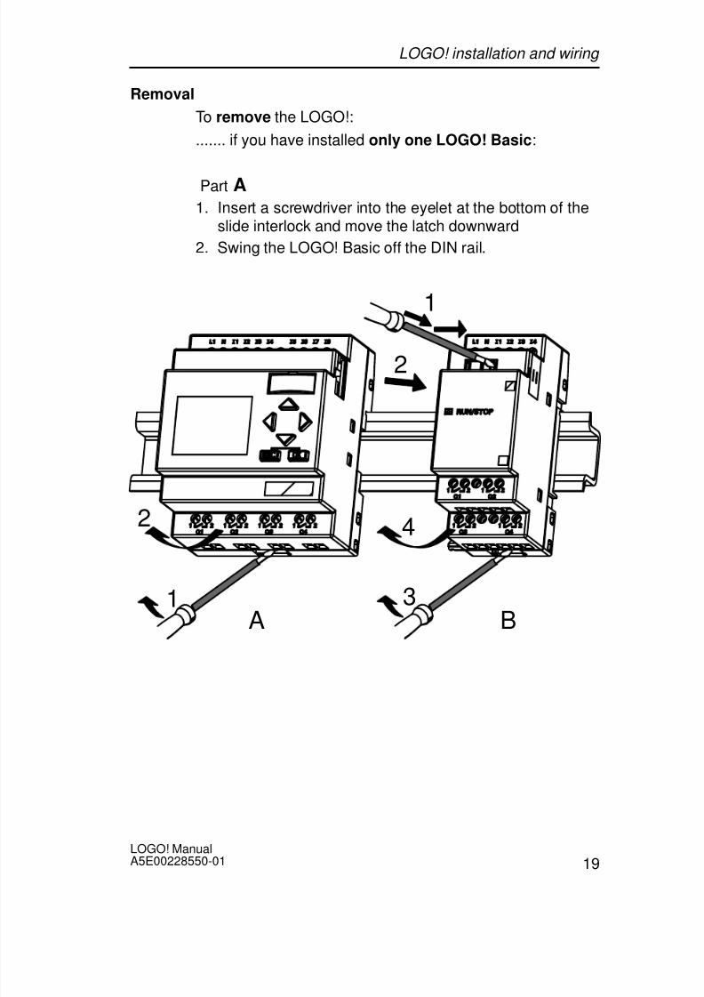
Removal
To remove the LOGO!:
....... if you have installed only one LOGO! Basic:
Part A1. Insert a screwdriver into the eyelet at the bottom of the
slide interlock and move the latch downward
2. Swing the LOGO! Basic off the DIN rail.
1
2
1
2
3
4
A B
LOGO! installation and wiring

8/10/2019 0900766b805c2bc6
http://slidepdf.com/reader/full/0900766b805c2bc6 32/341
LOGO! ManualA5E00228550-01
20
....... if you have connected at least one expansion mod-ule to the LOGO! Basic:
Part B1. Using a screwdriver, push the integrate slide interlock
to the right
2. Slide the expansion module off towards the right
3. Insert a screwdriver into the eyelet at the bottom of theslide interlock and lever it downward
4. Swing the expansion module off the profile rail.
Repeat steps 1 to 4 for all other expansion modules.
Note
If you have connected more than one expansion module, itis advisable to start removal with the last module at theright-hand side.
Make sure that the slide interlock of the module to beinstalled/removed is not engaged in the next module.
LOGO! installation and wiring

8/10/2019 0900766b805c2bc6
http://slidepdf.com/reader/full/0900766b805c2bc6 33/341

8/10/2019 0900766b805c2bc6
http://slidepdf.com/reader/full/0900766b805c2bc6 34/341
LOGO! ManualA5E00228550-01
22
Drilling template for wall-mounting
Before you can wall-mount the LOGO!, you need to drillholes using the template shown below.
53.5 +/– 0.2 35.5 +/– 0.2
n x 35.5 +/– 0.2
9 8
+ / –
0 . 3
Bore hole for M4 screwTightening torque 0.8 to 1.2 N/mLOGO! BasicLOGO! expansion module
1 2
1
2
All dimensions in mm
2 2
LOGO! installation and wiring

8/10/2019 0900766b805c2bc6
http://slidepdf.com/reader/full/0900766b805c2bc6 35/341
23LOGO! ManualA5E00228550-01
2.3 Wiring the LOGO!
Wire the LOGO! using a screwdriver with a 3-mm blade.
You do not need wire ferrules for the terminals. Permittedconductor cross-sections:
1 x 2.5 mm2
2 x 1.5 mm2 for each second terminal chamber
Tightening torque: 0.4...0.5 N/m or 3...4 lbs/in
Note
Always cover the terminals after you have completed theinstallation. To protect LOGO! adequately from impermissi-ble contact to live parts, local standards must be compliedwith.
2.3.1 Connecting the power supply
The 230-V versions of LOGO! are suitable for operationwith rated voltages of 115 V AC/DC and 240 V AC/DC. TheLOGO! 24-V and 12-V versions can be operated with a24 VDC, 24 V AC or 12 VDC power supply. For informationon permissible voltage tolerances, line frequencies andpower consumption, refer to the installation instructions inthe Product Information supplied with your device and tothe technical data in Appendix A.
Note
A power failure may cause an additional edge triggeringsignal at the special functions, for example.
Data of the last uninterrupted cycle are stored in LOGO!.
LOGO! installation and wiring

8/10/2019 0900766b805c2bc6
http://slidepdf.com/reader/full/0900766b805c2bc6 36/341
LOGO! ManualA5E00228550-01
24
Connecting LOGO!
To connect LOGO! to the power supply:
L1L+
NM
LOGO! .....
with DC power supply
LOGO! .....
with AC power supply
Protection with safety fuseif required (recommended) for:12/24 RC...: 0.8 A24: 2.0 A
To suppress surge voltages,install varistors (MOV) with anoperating voltage at least 20 %above the rated voltage.
ML+ I1 I2 I3 I4 I5 I1 I2 I3 I4L1 N
Note
LOGO! is a double-insulated switchgear. It is not requiredto connect an equipment grounding conductor.
Circuit protection with AC voltage
To suppress voltage peaks on the power supply lines, you
can install a metal oxide varistor (MOV) (MOV). Make surethat the operating voltage of the varistor (MOV) used lies atleast 20 % above the rated voltage (for example S10K275).
LOGO! installation and wiring

8/10/2019 0900766b805c2bc6
http://slidepdf.com/reader/full/0900766b805c2bc6 37/341
25LOGO! ManualA5E00228550-01
2.3.2 Connecting LOGO! inputs
Requirements
At the inputs you connect sensor elements such as: mo-mentary switches, switches, light barriers, daylight controlswitches etc.
Sensor characteristics for LOGO!
LOGO! 12/24 RC/RCo
LOGO! DM8 12/24 R
LOGO! 24/24o
LOGO! DM8 24
I1 ... I6 I7, I8 I1 ... I6 I7, I8
Signal status 0 < 5 VDC < 5 VDC < 5 VDC < 5 VDCInput current < 1.0 mA < 0.05 mA < 1.0 mA < 0.05 mA
Signal status 1 > 8 V DC > 8 V DC > 8 V DC > 8 V DC
Input current > 1.5 mA > 0.1 mA > 1.5 mA > 0.1 mA
LOGO! 24
RC/RCo (AC)
LOGO! DM8
24 R (AC)
LOGO! 24
RC/RCo (DC)
LOGO! DM8
24 R (DC)
LOGO! 230
RC/RCo (AC)
LOGO! DM8
230 R (AC)
LOGO! 230
RC/RCo (DC)
LOGO! DM8
230 R (DC)
Signal status 0 < 5 V AC < 5 V DC < 40 V AC < 30 V DC
Input current < 1.0 mA < 1.0 mA < 003 mA < 003 mA
Signal status 1 > 12 V AC > 12 V DC > 79 V AC > 79 V DC
Input current > 2.5 mA > 2.5 mA > 0.08 mA > 0.08 mA
Note
The digital inputs of LOGO! 230 RC/RCo are divided intotwo groups, each consisting of four inputs. Within thesame group, all inputs must be operated on the samephase. Different phases are only possible between thegroups.Example: I1 to I4 on phase L1, I5 to I8 on phase L2.
Inputs within the LOGO! DM8 230R may not be connectedto different phases.
LOGO! installation and wiring

8/10/2019 0900766b805c2bc6
http://slidepdf.com/reader/full/0900766b805c2bc6 38/341
LOGO! ManualA5E00228550-01
26
Sensor connections
Connecting glow lamps and 2-wire proximity switches(Bero) to LOGO! 230 RC/230 RCo or LOGO!
DM8 230 R (AC)L1
N
NL1
C3SB1420-3D
Order number for C:
SiemensSwitchgear & Systems
X-capacitor 2.5 kV, 100 nF
Take the quiescent current of any 2-wire proximity switchesused into account. The level of the quiescent current ofsome 2-wire proximity switches is high enough to trigger alogical ”1” signal at the LOGO! input. You should thereforecompare the quiescent current of the proximity switches
with the technical data of inputs Appendix A.
LOGO! installation and wiring

8/10/2019 0900766b805c2bc6
http://slidepdf.com/reader/full/0900766b805c2bc6 39/341
27LOGO! ManualA5E00228550-01
Restrictions
Signal status transitions 0 1 / 1 0
After a 0 to 1 or 1 to 0 transition, the signal must remain
constant at the input at least for the duration of one pro-gram cycle, so that LOGO! can detect the new signal sta-tus.
The program execution time is determined by the size ofthe circuit program. Appendix B contains a benchmark testroutine that you can use to determine the current scancycle time.
Special features of LOGO! 12/24 RC/RCo and LOGO! 24/24o
High-speed inputs: I5 and I6 These versions are also equipped with high-speed countinginputs (Up/down counters, Threshold triggers). The restric-tions mentioned earlier do not apply to these high-speedinputs.
Note
The high-speed inputs I5 and I6 are the same as in theprevious versions 0BA0 to 0BA3, i.e. a circuit programthat is written in these versions can be transferred to thenew 0BA4 units by means of the programming softwareLOGO! SoftComfort, without any changes to these fea-tures. In contrast to this, you need to modify circuit pro-grams written for a LOGO!...L version (high-speed inputsI11/I12).
Expansion modules do not have high-speed inputs.
Analog inputs: I7 and I8
The inputs I7 and I8 of LOGO! versions 12/24RC/RCo and24/24o can be used both as standard digital inputs and asanalog inputs. The input mode is defined in the LOGO! cir-cuit program.
The inputs I7 / I8 provide digital functions, and the inputsAI1 and AI2 provide analog functions.
See also Chapter 4.1.
LOGO! installation and wiring

8/10/2019 0900766b805c2bc6
http://slidepdf.com/reader/full/0900766b805c2bc6 40/341
LOGO! ManualA5E00228550-01
28
Note
The LOGO! AM 2 expansion module provides further ana-
log inputs. The LOGO! AM 2 PT100 expansion moduleprovides Pt100 inputs.
Always use twisted and shielded cables for analog signals,and keep these as short as possible.
Sensor connections
To connect sensors to the LOGO! :
LOGO! 12/24 ....L+
M
The inputs of these devices not iso-
lated and therefore require a com-
mon reference potential (chassis
ground ).
At the LOGO! 12/24RC/RCo and
LOGO! 24/24o modules, you can
tap analog signals between the
supply voltage and chassis ground.
ML+ I1 I2 I3 I4 I5 I8
LOGO! 230 ....
L1
N
L3
L2The inputs of these de-
vices are arranged in 2
groups, each consisting
of 4 inputs. Different
phases are only possible
between blocks, but notwithin the blocks.NL1 I1 I2 I3 I4 I5 I6
LOGO! installation and wiring

8/10/2019 0900766b805c2bc6
http://slidepdf.com/reader/full/0900766b805c2bc6 41/341
29LOGO! ManualA5E00228550-01
!Warning
Current safety regulations (VDE 0110, ... and IEC 61131-2,... as well as cULus) do not permit the connection of differ-ent phases to an AC input group (I1 to I4 or I5 to I8) or tothe inputs of a digital module.
LOGO! AM 2
Current mea-surement
Voltage measurement
ML+
L+M
Current
U1 I2 M2 U2I1 M1
PE
L+
M
Reference
current0...20
mA
1
2
1
PE
Earth
Cable shielding
PE terminal for con-necting earth andthe shielding of the
analog measuringcable
3 3 DIN railRUN/STOP
2
M
ML+
LOGO! installation and wiring

8/10/2019 0900766b805c2bc6
http://slidepdf.com/reader/full/0900766b805c2bc6 42/341

8/10/2019 0900766b805c2bc6
http://slidepdf.com/reader/full/0900766b805c2bc6 43/341
31LOGO! ManualA5E00228550-01
2.3.3 Connecting outputs
LOGO! ...R...
The LOGO! ...R... version is equipped with relay outputs.The potential of the relay contacts is isolated from thepower supply and the inputs.
Requirements for relay outputs
You can connect various loads to the outputs, e.g. lamps,fluorescent lamps, motors, contactor relays etc. For infor-mation on the properties required for the loads connectedto the LOGO! ...R..., refer to Appendix A.
Connecting
This is how you connect the load to LOGO! ...R...:
Protection with automatic circuit-breaker, max. 16 A, characteristicsB16, e.g.: Power circuit-breaker 5SX2 116-6 (if required)
DM8...R
1 2Q1 Q2
1 2
Q5 Q61 2 1 2
Load Load
LOGO! installation and wiring

8/10/2019 0900766b805c2bc6
http://slidepdf.com/reader/full/0900766b805c2bc6 44/341
LOGO! ManualA5E00228550-01
32
LOGO! with solid-state outputs
LOGO! versions with solid-state outputs can be identifiedby the fact that the letter R is missing from their type name.
The outputs are short circuit-proof and overload-proof. Anauxiliary load voltage supply is not necessary, becauseLOGO! supplies the load voltage.
Requirements for solid-state outputs
The load connected to LOGO! must have the followingcharacteristics:
The maximum switched current is 0.3 A per output.
Connecting
This is how you connect the load to a LOGO! with solid-state outputs:
Load: 24 V DC, 0.3 A max.
DM8 24
Q1 Q2M M
Q5 Q6M M
Load Load
LOGO! installation and wiring

8/10/2019 0900766b805c2bc6
http://slidepdf.com/reader/full/0900766b805c2bc6 45/341
33LOGO! ManualA5E00228550-01
2.4 Switching on the LOGO!/Power On
LOGO! does not have a power switch. The reaction of
LOGO! during startup depends on Whether a circuit program is stored in LOGO!
Whether a program module (Card) is inserted
Whether this is a LOGO! version without display unit(LOGO!...o)
The status of LOGO! at the time of power failure.
All possible reaction of LOGO! are described on the follow-
ing page.
LOGO! installation and wiring

8/10/2019 0900766b805c2bc6
http://slidepdf.com/reader/full/0900766b805c2bc6 46/341
LOGO! ManualA5E00228550-01
34
2002-01-31
2002-01-31 Mo 09:00
2002-01-31
Mo
09:00
>Program..Card..Clock..Start
With stored
program fromLOGO!
&
B1
Q1
No program inmemory
(empty)
(with program)
or
LOGO!in RUN mode
(empty)
(with pro-gram)
or
Program inmemory
(empty)
or
with a pro-gram copiedfrom the pro-gram module(Card) inLOGO!
Before power off After power on
(with program)
with storedprogram fromLOGO!
with programcopied from thprogram modul(Card) in
LOGO!
2003-01-27
Mo 09:00
......
......
>Program..Card..Clock..Start
>Program..Card..Clock..Start
No program Press ESC
LOGO! inRUN mode
No Program Press ESC
Mo 09:00
I:0.. 1234567891..01234567892..01234
Q:
0.. 1234567891..0123456
0.. 1234567891..01234567892..01234
I:
B3:
Cnt = 0028
Par = 0300
0.. 1234567891..01234567892..01234
I:
LOGO! installation and wiring

8/10/2019 0900766b805c2bc6
http://slidepdf.com/reader/full/0900766b805c2bc6 47/341
35LOGO! ManualA5E00228550-01
You can also memorize four simple rules for startingLOGO! :
1. If neither the LOGO! nor the inserted program module(Card) contains a circuit program, the LOGO! (with dis-play unit ) reports: ’No Program / Press ESC’.
2. A circuit program on the program module (Card) is auto-matically copied to LOGO!. The circuit program in theLOGO! is overwritten.
3. If there is a circuit program in LOGO! or on the programmodule (Card), LOGO! adopts the operational state ithad prior to POWER-OFF. Versions without display unit(LOGO!...o) automatically change from STOP to RUN
(LED changes from red to green).4. If you have enabled retentivity at least for one function,
or a function is permanently retentive, the current valuesare retained at POWER-OFF.
Note
When a power failure occurs while you are entering a cir-
cuit program, the program in LOGO! will be deleted afterpower is returned.
Before you modify the circuit program, you should there-fore save a backup copy of your original to a programmodule (Card) or to a computer (LOGO!Soft Comfort).
LOGO! installation and wiring

8/10/2019 0900766b805c2bc6
http://slidepdf.com/reader/full/0900766b805c2bc6 48/341
LOGO! ManualA5E00228550-01
36
LOGO! Basic operating states
LOGO! Basic/Pure knows two operating states: STOP andRUN
STOP RUN
The display shows:’No Program’(not LOGO!...o)
Switching LOGO! to pro-gramming mode(not LOGO!...o)
LED is red
(only LOGO!...o)
Display: Screen mask formonitoring I/Os and mes-sages (after START in themain menu)(not LOGO!...o)
Switching LOGO! to pa-rameter assignment mode(not LOGO!...o)
LED is green(only LOGO!...o)
Action of LOGO!:
The inputs data are notfetched.
The circuit program is notexecuted
The relay contacts are per-manently open or the solid-state outputs are switchedoff
Action of LOGO!:
LOGO! reads the status ofthe inputs
LOGO! uses the circuit pro-gram to calculate the sta-tus of the outputs
LOGO! switches the relay/ solid-state outputs on or off
LOGO! expansion modules, operating states
LOGO! expansion modules know three operating states:The LED is lit green, red or orange.
LED is lit
Green (RUN) Red (STOP) Orange
The expansionmodule communi-cates with the de-vice to its left
The expansionmodule does notcommunicate withthe device to its left
Initialization phaseof the expansionmodule
LOGO! installation and wiring

8/10/2019 0900766b805c2bc6
http://slidepdf.com/reader/full/0900766b805c2bc6 49/341

8/10/2019 0900766b805c2bc6
http://slidepdf.com/reader/full/0900766b805c2bc6 50/341
LOGO! ManualA5E00228550-01
38
A small example in the first part of this chapter introducesthe operating principle of LOGO!.
We shall first show you the meaning of two basic terms,namely the connector and the block.
In the next step, we shall create a circuit program basedon a simple conventional circuit, which you ...
can enter directly in LOGO! in the third step.
It will take you only a few pages of this manual store yourfirst executable circuit program in the LOGO! unit. With asuitable hardware (switches etc.), you will then be able tocarry out first tests.
Programming LOGO!

8/10/2019 0900766b805c2bc6
http://slidepdf.com/reader/full/0900766b805c2bc6 51/341
39LOGO! ManualA5E00228550-01
3.1 Connectors
The LOGO! is equipped with inputs and outputs
Example of a configuration with several modules:
L+ M I13I14I15I16
Q11
Q9
Q12
Q10
RUN/STOP
L+ M
A!3
RUN/STOP
L+ M I1 I2 I3 I4 I5 I6
Q1 Q2 Q3 Q4
Inputs
Outputs
AI1 AI2 L+ M I9 I10I11I12
Q7
Q5
Q8
Q6
RUN/STOP
M3U3AI4M4U4
Analog inputs
1 2 1
2 1 2 1 21 2 1 2 1 2 1 2
1 2 1 2
1 2 1 2
PE
INPUT 2x (..10 V/..20 mA)
L+ M
Each input is identified by the letter I plus a number. When
you take a look at the LOGO! from the front, you can seethe input terminals at the top. Only the analog modulesLOGO! AM 2 and AM 2 PT100 have the inputs at the bot-tom.
Each output is identified by the letter Q plus a number. Inthe figure, you can see the output terminals at the bottom.
Programming LOGO!

8/10/2019 0900766b805c2bc6
http://slidepdf.com/reader/full/0900766b805c2bc6 52/341
LOGO! ManualA5E00228550-01
40
Note
LOGO! can recognize, read and switch the I/O of all ex-
pansion modules, regardless of their type. The I/O are pre-sented in the installation order of the modules.
The following I/Os and flag blocks are available for the cre-ation of your circuit program: : I1 to I24, AI1 to AI8, Q1 toQ16, AQ1 and AQ2, M1 to M24 and AM1 to AM6. Alsoavailable are the shift register bits S1 to S8, 4 cursor keysC , C , C and C , as well as 16 blank outputs X1 toX16. More details are found in Chapter 4.1.
The following applies to the inputs I7 and I8 of LOGO!12/24... and LOGO! 24/24o versions: If Ix is used in thecircuit program, this input signal is digital; signals at AIxare analog. Input AIx can only represent the connector thatis actually capable of handling analog signals.
LOGO!’s connectors
The term connector refers to all connections and states inLOGO! .
The I/O status can be ’0’ or ’1’. Status ’0’ means that theinput does not carry a voltage. Status ’1’ means that theinput carries voltage.
We have introduced ’hi’, ’lo’ and ’x’ connectors to make iteasier for you to create the circuit program:’hi’ (high) is assigned the status ’1’,’lo’ (low) is assigned the status ’0’.
You do not have to use all the of connectors of a block. Thecircuit program automatically assigns the unused connec-tors a status that ensures proper functioning of the relevantblock. If you prefer to do so, you can identify unused con-nectors with an ’x’.
For information on the meaning of the term “block”, refer toChapter 3.2.
Programming LOGO!

8/10/2019 0900766b805c2bc6
http://slidepdf.com/reader/full/0900766b805c2bc6 53/341
41LOGO! ManualA5E00228550-01
LOGO! knows the following connectors:
Con-
nectors
LOGO! Basic / Pure DM AM
Inputs LOGO! 230RC/RCo,LOGO! 24 RC/RCo
Two groups:I1... I4 andI5 ... I8
I9 ... I24 AI1...AI8
LOGO! 12/24RC/ RCo, LOGO! 24/24o
I1... I6, I7, I8AI1, AI2
I9 ... I24AI3...AI8
Outputs Q1...Q4 Q5 ...Q16
none
lo Logical ’0’ signals (off)
hi Logical ’1’ signals (on)
x An existing connection that is not used
DM: Digital module. AM: Analog module.
Programming LOGO!

8/10/2019 0900766b805c2bc6
http://slidepdf.com/reader/full/0900766b805c2bc6 54/341
LOGO! ManualA5E00228550-01
42
3.2 Blocks and block numbers
This chapter shows you how to use LOGO! elements to
create complex circuits and how blocks and I/O are inter-connected.
In Chapter 3.3 we are going to show you how to transforma conventional circuit to obtain a LOGO! circuit program.
Blocks
A block in LOGO! represents a function that is used to con-vert input information into output information. Previouslyyou had to wire the individual elements in a control cabinet
or terminal box.When you create the circuit program, you interconnect theblocks. To do so, simply select the connection you requirefrom the Co menu The menu name Co is an abbreviationof the term “Connector”.
Logic operations
The most elementary blocks are the logic operations:
AND
OR
...
I1
I2
x
1Inputs I1 and I2 are here connectedto the OR block. The last two inputsof the block remain unused and areidentified be the creator of the circuitprogram with an ’x’.
Qx
These special functions offer you a significantly higher per-formance:
Pulse relay
Up/down counter
On-delay
Softkey
....
In Chapter 4 you will find a full list of the LOGO! functions.
Programming LOGO!

8/10/2019 0900766b805c2bc6
http://slidepdf.com/reader/full/0900766b805c2bc6 55/341
43LOGO! ManualA5E00228550-01
View of blocks on the LOGO! display
The figure below shows a typical view of the LOGO! dis-play. As you can see, it can show only one block at a time.
We have therefore introduced block numbers to help youcheck the circuit structure.
1B2
I3 Q1
B1
View of the LOGO! display
x
Block number -assigned byLOGO!A further block is con-
nectedat this point
Input
This connector is not required OutputBlock
x
Assigning a block number
LOGO! assigns each new block a circuit program a blocknumber.
LOGO! uses these block numbers to indicate the block in-
terconnections. Hence, these numbers primarily representa help for your orientation in the circuit program.
I1
I2
I3
1
B1
B2
B2
1
B3 Q1
B1
B1
Scrolling the circuit program using the key
I4
I5
I6
1
B1
These blocks areinterconnected
Block numbers
Q1
x
B3
x
x x
Programming LOGO!

8/10/2019 0900766b805c2bc6
http://slidepdf.com/reader/full/0900766b805c2bc6 56/341
LOGO! ManualA5E00228550-01
44
The figure above shows you three views of the LOGO! dis-play, which represent the circuit program. As you can see,LOGO! interconnects the blocks using their numbers.
Advantages of the block numbersYou can connect almost any block to an input of the currentblock by means of its block number. In this way, you canreuse the interim results of logical or other operations, re-duce programming effort, save memory space and cleanup your circuit layout. To do so, however, you need to knowhow LOGO! has named the blocks.
Note
We advise you to create an organizational program chart.You will find this a valuable help when you create the cir-cuit program, because you can enter all block numbersassigned by LOGO! in this chart.
By using the LOGO!Soft Comfort software to program theLOGO!, you can directly create a function chart of yourcircuit program. LOGO!Soft Comfort also allows you to as-
sign 8-character names to up to 64 blocks, and to viewthese on the LOGO! display in parameter assignment andprogramming mode (see Chapter 3.4).
Programming LOGO!

8/10/2019 0900766b805c2bc6
http://slidepdf.com/reader/full/0900766b805c2bc6 57/341
45LOGO! ManualA5E00228550-01
3.3 The way to LOGO!, starting with the cir-
cuit diagram
View of a circuit diagram
You know, of course, how a circuit logic is represented in acircuit diagram. Nevertheless, here is an example:
K1
S1 K1S2
E1
The load E1 is switched on
and off by means of the
switches (S1 OR S2) AND S3.
S3Relay K1 picks up when thecondition (S1 OR S2) AND S3
is met.
Creating this circuit with LOGO!
In LOGO! you create a circuit logic by interconnectingblocks and connectors:
S1 ... S3 Wiring of the inputs
I3
x
Q1
&1I1
I2
x
Circuit program in LOGO!
Wiring of the outputs
L
1
N
Programming LOGO!

8/10/2019 0900766b805c2bc6
http://slidepdf.com/reader/full/0900766b805c2bc6 58/341
LOGO! ManualA5E00228550-01
46
Note
Although you have four inputs available for logic opera-
tions (Basic functions, see Chapter 4.2), most of the viewswill only show three inputs for reasons of clarity. You pro-gram this fourth input and assign parameters just like youdo with the other three inputs.
To create a circuit logic in LOGO!, start at the output.
The output is the load or relay that is to be switched.
Convert the circuit logic into blocks by working through the
circuit, starting at the output and ending at the input:Step 1: The make contact S3 is interconnected in series tooutput Q1 and to a further circuit element. A series connec-tion corresponds with the AND block:
I3
x
Q1
&
Step 2: S1 and S2 are connected in parallel. A parallel cir-cuit corresponds with the OR block:
I3
x
Q1
&1I1
I2
x
Unused inputsThe circuit program automatically assigns the unused con-nectors a status that ensures proper functioning of the rele-vant block. If you like, you can label unused connectorswith an ’x’ identifier.
In our example we shall use only two inputs of the ORblock and two inputs of the AND block; the relevant unusedthird and fourth inputs are identified at the connector withan ’x’.
Now connect the I/Os to the LOGO! .
Programming LOGO!

8/10/2019 0900766b805c2bc6
http://slidepdf.com/reader/full/0900766b805c2bc6 59/341
47LOGO! ManualA5E00228550-01
Wiring
Connect the switches S1 to S3 to the screw terminals ofyour LOGO! :
S1 to connector I1 of LOGO! S2 to connector I2 of LOGO!
S3 to connector I3 of LOGO!
The output of the AND block controls the relay at outputQ1. The load E1 is connected to output Q1.
Wiring example
The following figure shows you the wiring, based on a230 V AC version of LOGO!.
L1N
Input wiring
Output wiring
S3
S2
S1
L1
N
NL1 I1 I2 I3 I4
1 2Q1
Programming LOGO!

8/10/2019 0900766b805c2bc6
http://slidepdf.com/reader/full/0900766b805c2bc6 60/341

8/10/2019 0900766b805c2bc6
http://slidepdf.com/reader/full/0900766b805c2bc6 61/341
49LOGO! ManualA5E00228550-01
Rule 2Outputs and inputs
Always create your circuit program by working from theoutput to the input.
You can connect an output to several inputs, but not thesame input to several outputs.
Within the same program path you may not connect anoutput to an upstream input. For such internal recur-sions you should interconnect flags or outputs.
Rule 3Cursor and cursor movement
The following applies when you edit a circuit program: You can move the cursor when it appears in the form
of an underscore:
– Press , , or to move the cursor in the circuitprogram.
– Press OK to change to ”Select connector/block”
– Press ESCto exit programming mode.
You select a connector/block
when the cursor appears as solid square – Press or to select a connector or a block.
– Confirm with OK.
– Press ESC to return to the previous step.
Rule 4Planning
Before you start to create a circuit program, you shouldeither first create design on paper or program LOGO!
directly using LOGO!Soft Comfort.
LOGO! can only save complete and faultless circuit pro-grams.
Programming LOGO!

8/10/2019 0900766b805c2bc6
http://slidepdf.com/reader/full/0900766b805c2bc6 62/341

8/10/2019 0900766b805c2bc6
http://slidepdf.com/reader/full/0900766b805c2bc6 63/341
51LOGO! ManualA5E00228550-01
3.6 Writing and starting the circuit program
After you have designed a circuit, you want to write it to
your LOGO! . The small example below shows how to dothis.
3.6.1 Select programming mode
You have connected the LOGO! to the power supply andswitched it on. The display now shows you the message:
No Program Press ESC
Switch the LOGO! to programming mode by pressing theESC. This will take you to the main menu of the LOGO!:
>Program..
Card..Clock..Start
LOGO!’s main menu
The first character in the first line is the ”>” cursor. Pressand to move the ”>” cursor up and down. Move it to ”Pro-gram..” and confirm with OK. LOGO! opens the program-ming menu.
>Edit..Clear PrgPassword
The LOGO!’s programming menu
Programming LOGO!

8/10/2019 0900766b805c2bc6
http://slidepdf.com/reader/full/0900766b805c2bc6 64/341
LOGO! ManualA5E00228550-01
52
Here you can also move the ”>” cursor by pressing and. Move the ”>” cursor to ”Edit..” (for editing, i.e. input) and
confirm with OK.
>Edit PrgEdit Name Memory?
The Edit menu of LOGO!
Move the ”>” cursor to ”Edit Prg” (for editing the circuitprogram) and confirm with OK. LOGO! now shows you thefirst output:
The first output of LOGO!
Q1
You are now in programming mode. Press and to se-lect the other outputs. Now start to edit your circuit pro-gram.
Note
Because we have not yet saved a password for the circuitprogram in LOGO!, you can directly enter editing mode.When you select “Edit Prg“ after you have saved a pass-word-protected circuit program, you are prompted to entera password and to confirm it with OK. You can only edit
the program after you have entered the correct password(see Chapter 3.6.5.).
Programming LOGO!

8/10/2019 0900766b805c2bc6
http://slidepdf.com/reader/full/0900766b805c2bc6 65/341
53LOGO! ManualA5E00228550-01
3.6.2 The first circuit program
Let us now take a look at the following parallel circuit con-sisting of two switches.
Circuit diagram
The corresponding circuit diagram:
K1
S1K1
S2
E1
The load is switched on withS1 OR S2. LOGO! interpretsthis parallel circuit as an ’OR’logic, because S1 OR S2switches on the output.
Translated into a LOGO! circuit program this means: RelayK1 is at output Q1 is controlled by means of an OR block.
Circuit program
S1 is connected to the I1 and and S2 to the I2 input con-nector of the OR block.
The corresponding layout of the circuit program in LOGO!:
I1
I2
xQ1
1
Programming LOGO!

8/10/2019 0900766b805c2bc6
http://slidepdf.com/reader/full/0900766b805c2bc6 66/341
LOGO! ManualA5E00228550-01
54
Wiring
The corresponding wiring:
L1 N I4 I5 I6 I7 I8
Q1 Q2 Q3 Q4
L1
N
S1S2
L
N
I1I1 I3I1I1 I1I1I1I2
1 2 1 2 1 2 1 2
S1 switches input I1, while S2 switches input I2. The load isconnected to the relay Q1.
3.6.3 Circuit program input
Let us now write the circuit program, starting at the outputand working towards the input. LOGO! initially shows theoutput:
The first LOGO! output
Q1
Programming LOGO!

8/10/2019 0900766b805c2bc6
http://slidepdf.com/reader/full/0900766b805c2bc6 67/341
55LOGO! ManualA5E00228550-01
You will see an underscore below the Q in Q1, which is thecursor. The cursor indicates your current position in thecircuit program. You can move the cursor by pressing the
, , and keys. Now press the key. The cursormoves to the left.
The cursor indicates your current posi-tion in the circuit program.
Q1–
At this point you enter only the first (OR) block. Press OK
to select editing mode.
The cursor is displayed as a solidsquare: You can now select a connec-tor or a block
Q1Co
The cursor no longer appears in the form of an underscore;
but instead as a flashing solid square. LOGO! offers youhere various options.
Select GF (basic functions) by pressing the key until GFappears, and confirm with OK. LOGO! now shows the firstblock from the list of basic functions:
The AND is the first block of the basicfunctions list. The solid square cursorprompts you to select a block.
&B1
Q1
Programming LOGO!

8/10/2019 0900766b805c2bc6
http://slidepdf.com/reader/full/0900766b805c2bc6 68/341
LOGO! ManualA5E00228550-01
56
Now press or until the OR block appears on the dis-play:
1
B1
Q1
The solid square cursor is still posi-tioned on the block.
Press OK to confirm your entries and exit the dialog.
1
The display now shows:
B1
Q1
B1
1
Q1
Your complete circuitprogram layout
Blocknumber–
You have now entered the first block. Each new block isautomatically assigned a block number. The only thing leftto do is to interconnect the block inputs. This is how it isdone:
Press OK.
1
The display now shows:
B1
Q1Co
Select the Co list: Press OK
1
The display now shows:
B1
Q1x
Programming LOGO!

8/10/2019 0900766b805c2bc6
http://slidepdf.com/reader/full/0900766b805c2bc6 69/341
57LOGO! ManualA5E00228550-01
The first element of the Co list is the ”Input not used” char-acter, namely the ’x’. Press or to select input I1.
Note
Press to go the start of the Co list: I1, I2 .... to lo, thenagain ’x’. Press to go to the end of the Co list: lo, hi, Q..... to I1, and once again ’x’.
1Q1
I1
B1
Press OK. I1 is now connected to the input of the ORblock. The cursor jumps to the next input of the OR block.
1
The display now shows:
B1
Q11
Q1
Your complete circuit programin LOGO! up to now:
I1I1
B1
–
Now you connect input I2 to the input of the OR block. Youalready know how to do this:
1. Switch to editing mode: Press OK
2. To select the Co list: Press or
3. To confirm the Co list with: Press OK
4. To select I2: Press or
5. To apply I2: Press OK
Programming LOGO!

8/10/2019 0900766b805c2bc6
http://slidepdf.com/reader/full/0900766b805c2bc6 70/341
LOGO! ManualA5E00228550-01
58
I2 is now connected to the input of the OR block:
1
The display now shows:
B1
Q11
Q1
I1 I1
B1
I2I2
Your circuit program layout inLOGO! up to now
We do not need the last two inputs of the OR block for thiscircuit program. You can mark the unused inputs with an ’x’.Enter the ’x’ character twice:
1. Switch to editing mode: Press OK
2. To select the Co list: Press or
3. To accept the Co list: Press OK
4. To select ’x’: Press or
5. To apply x: Press OK
LOGO! returns to output Q1.
The display now shows:
1
Q1
This is the layout of yourcircuit program
I1
B1
I2Q1B1x
Programming LOGO!

8/10/2019 0900766b805c2bc6
http://slidepdf.com/reader/full/0900766b805c2bc6 71/341

8/10/2019 0900766b805c2bc6
http://slidepdf.com/reader/full/0900766b805c2bc6 72/341
LOGO! ManualA5E00228550-01
60
Note
LOGO! has now saved your circuit program to nonvolatile
memory. The circuit program remains in the LOGO! me-mory until you explicitly delete it.
3.6.4 Assigning a circuit program name
You can assign your circuit program a name that consistsof up to 16 uppercase/lowercase letters, numbers and spe-cial characters.
In the programming menu:
1. To move the “>” cursor to ’Edit..’: Press or
2. To accept ’Edit’: Press OK
3. Move the “>” cursor to ’Edit Name’: Press or
4. To accept ’Edit Name’: Press OK
Press and to list the alphabet from A (a) to Z (z), num-bers and special characters, either in ascending or de-
scending order. You can select any letter, number or char-acter.
To enter a space character, simply movie the cursor withto the next position. This character is the first one in the list.
Examples:
Press once to select an “ A ” four times to select “ { ”, etc.
The following character set is available:
A B C D E F G H I J K L M N O
P Q R S T U V W X Y Z a b c d e
f g h i j k l m n o p q r s t u
v w x y z 0 1 2 3 4 5 6 7 8 9 !
” # $ % & ’ ( ) * + , – . / : ;
< = > ? @ [ \ ] ^ _ ‘ { | } ~
Programming LOGO!

8/10/2019 0900766b805c2bc6
http://slidepdf.com/reader/full/0900766b805c2bc6 73/341
61LOGO! ManualA5E00228550-01
Let us assume you want to name your circuit program“ABC”:
5. Select “ A”: Press
6. Move to the next letter: Press7. Select “ B”: Press
8. Move to the next letter: Press
9. Select “ C”: Press
10.To confirm the complete name: Press OK
Your circuit program is now named “ABC”, and you are re-turned to the programming menu.
To change the name of your circuit program, proceed in
the same way.
Note
You can change the name of the circuit program only inprogramming mode. You can read the name both in pro-gramming and in parameter assignment mode
3.6.5 Password
You can protect a circuit program from unauthorized accessby assigning it a password.
To assign a password
A password may have a maximum length of 10 characters,and consists only of uppercase letters (A to Z). Directly at
the LOGO!, the password can be assigned, edited or deac-tivated only in the “Password” menu.
In the programming menu:
1. Move the “>” cursor to ’Password’: Press or
2. To confirm the ’Password’: Press OK
Press or to move up and down the alphabet to selectyour letters. Because LOGO! only provides uppercase let-ters for the password, you can quickly access to letters “at
the end“ of the alphabet by using the button:
Programming LOGO!

8/10/2019 0900766b805c2bc6
http://slidepdf.com/reader/full/0900766b805c2bc6 74/341
LOGO! ManualA5E00228550-01
62
Press once to select “Z”Press twice to select “Y”, etc.
Let us assign the password “AA” to our first circuit pro-
gram. The display now shows:
Old:No Password
New:
This procedure is the same as for entering the name of thecircuit program. Select “New” and enter:
3. Select “ A”: Press
4. To move to the next letter: Press
5. Select “ A”: Press
The display now shows:
Old:No Password
New:
6. To confirm the password: Press OK
Your circuit program is now protected with the password“AA”, and you are returned to the programming menu.
Programming LOGO!

8/10/2019 0900766b805c2bc6
http://slidepdf.com/reader/full/0900766b805c2bc6 75/341
63LOGO! ManualA5E00228550-01
Note
You can cancel the input of a new password with ESC. In
this case, LOGO! returns to the programming menu with-out saving the password.
You can also set your password using LOGO!Soft Comfort.You can not edit a password-protected circuit program atthe LOGO! or upload it to LOGO!Soft Comfort unless youenter the correct password.
To allow you to create and edit a circuit program for a pro-tected module (Card), you first need to assign a password
to this new program (see Chapter 6.1).
Changing the Password
You need to know the current password in order to changeit.
In the programming menu:
1. Move the ’>’ cursor to ’Password’: Press or
2. To confirm the ’Password’: Press OKSelect “Old” and enter your old password (in our case: ’AA’)by repeating steps 3 through 6 as described earlier.
The display now shows:
Old:AA
New:
Now you can select “New” to enter the new password, e.g.“ZZ”:
3. Select “Z”: Press
4. To move to the next letter: Press
5. Select “Z”: Press
Programming LOGO!

8/10/2019 0900766b805c2bc6
http://slidepdf.com/reader/full/0900766b805c2bc6 76/341
LOGO! ManualA5E00228550-01
64
The display now shows:
Old:AA
New:ZZ
6. To confirm your new password: Press OK
Your new password “ZZ” is now set, and you are returnedto the programming menu.
Deactivating the Password
Let us assume you want to deactivate the password forwhichever reason. For example, you want to allow anotheruser to edit your circuit program. You must know yourcurrent password (in our example “ZZ”), same as if youwere changing it.
In the programming menu:
1. Move the ’>’ cursor to ’Password’: Press or
2. To confirm the ’Password’: Press OK
Select “Old” and enter your current password under asdescribed in steps 3 to 5. Confirm your entries with OK.
The display shows:
Old:ZZ
New:
Clear the password by leaving the input box blank:
3. To confirm the “blank” password: Press OK
The password is ”cleared”, and you are returned to the pro-gramming menu.
Programming LOGO!

8/10/2019 0900766b805c2bc6
http://slidepdf.com/reader/full/0900766b805c2bc6 77/341
65LOGO! ManualA5E00228550-01
Note
This action disables the password prompt, and thus per-
mits access without password.Let the password prompt be deactivated for the time be-ing, in order to accelerate progress in our further exercisesand examples.
Password: Wrong Password!
When the user inputs the wrong password and confirms
the input with OK, LOGO! does not open editing mode, butreturns to the programming menu. This repeats itself overand again until you input the correct password.
Programming LOGO!

8/10/2019 0900766b805c2bc6
http://slidepdf.com/reader/full/0900766b805c2bc6 78/341
LOGO! ManualA5E00228550-01
66
3.6.6 Switching LOGO! to RUN mode
In the main menu, select RUN to start LOGO!.
1. To return to the main menu: Press ESC
2. Move the ’>’ cursor to ’Start’: Press or
3. To confirm ’Start’: Press OK
LOGO! runs the circuit program and and shows the follow-ing display:
Display field of the LOGO! in RUN mode
Date and current time-of-day(only for versions with real-time clock). This elementflashes if the date and timeare not set.
2003-01-27
Mo 09:00
Press
Inputs I1 to I9I:0.. 1234567891..01234567892..01234
Inputs I20 to I24
Inputs I10 to I19
Press
Q:0.. 1234567891..0123456
Outputs Q1 to Q9
Outputs Q10 to Q16
Press
Flags M1 to M9 M:0.. 123456789
1..01234567892..01234
Flags M20 to M24
Flags M10 to M19
Press
ESC+Key4 cursor keys for manual inter-vention in the circuit program(ESC+key)
Programming LOGO!

8/10/2019 0900766b805c2bc6
http://slidepdf.com/reader/full/0900766b805c2bc6 79/341
67LOGO! ManualA5E00228550-01
What is meant by: ”LOGO! is in RUN”?
In RUN mode, LOGO! executes the circuit program. To doso, LOGO! first reads the status at the inputs, determines
the status of the outputs by means of the user program,and switches these on or off according to your settings.
This is how LOGO! indicates the I/O status:
Q:0.. 1234567891..0123456
Input/output status is ’1’:invertedInput/output status is ’0’:not inverted
I:
In this example, only the inputs I1, I15, Q8 and Q12 are set“high“.
0.. 1234567891..01234567892..01234
Status indication on the display
I:0.. 1234567891..0123456789
2..01234
L1
N
S1 S2=1When switch S1 is closed,the status at input I1 is hi.
LOGO! computes the outputstates by means of the cir-cuit program.
Output Q1 = ’1’, in thiscase.
When Q1 = ’1’, LOGO! setsrelay Q1, and the load con-nected to Q1 is suppliedwith voltage.
I1 I2
Q1
Let us examinethis, using ourexample:
Q:0.. 1234567891..0123456
Programming LOGO!

8/10/2019 0900766b805c2bc6
http://slidepdf.com/reader/full/0900766b805c2bc6 80/341

8/10/2019 0900766b805c2bc6
http://slidepdf.com/reader/full/0900766b805c2bc6 81/341

8/10/2019 0900766b805c2bc6
http://slidepdf.com/reader/full/0900766b805c2bc6 82/341
LOGO! ManualA5E00228550-01
70
Press to select the SF list:
Q1SF
The SF list contains the specialfunction blocks.
Press OK.
The block of the first special function is shown:
Trg
Par Q1
When you select a special or basic functionblock, LOGO! shows you the relevant func-tion block. The solid square cursor is posi-
tioned on the block. Press or to selectthe required block.
Select your block (off-delay, see the next figure), and thenpress OK:
R
The added block is assigned the block num-ber B2. The cursor is positioned at the topinput of the added block.B1
ParQ1
B2
Before you press’OK’, this showsthe entry Trg
The B1 block previously connected to Q1 is automaticallyconnected to the uppermost input of the new block. Notethat you can only interconnect digital inputs with digital out-puts or analog inputs with analog outputs. The ’old’ blockwill otherwise be lost.
The off-delay block has three inputs. At the top is the trig-ger input (Trg) you use to start the off-delay time. In ourexample, the OR block B1 triggers the off-delay. You resetthe time and the output with a signal at the reset input. Setthe off-delay time at parameter T of the input Par.
Programming LOGO!

8/10/2019 0900766b805c2bc6
http://slidepdf.com/reader/full/0900766b805c2bc6 83/341

8/10/2019 0900766b805c2bc6
http://slidepdf.com/reader/full/0900766b805c2bc6 84/341

8/10/2019 0900766b805c2bc6
http://slidepdf.com/reader/full/0900766b805c2bc6 85/341
8/10/2019 0900766b805c2bc6
http://slidepdf.com/reader/full/0900766b805c2bc6 86/341
LOGO! ManualA5E00228550-01
74
Closing the programming mode
Although you were shown how to exit the programmingmode when you created your first circuit program,
here is a reminder:1. To return to the programming menu: Press ESC
2. To return to the main menu: Press ESC
3. To move the ’>’ cursor to ’Start’: Press or
4. To confirm ’Start’: Press OK
LOGO! is back in RUN mode:
You can press orto scroll the pages and to monitor the I/Ostates.
2003-01-27 Mo 09:30
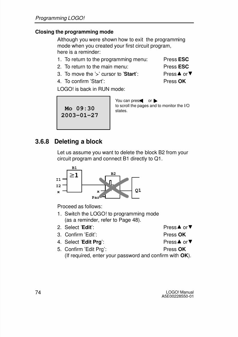
3.6.8 Deleting a block
Let us assume you want to delete the block B2 from yourcircuit program and connect B1 directly to Q1.
Q1
I1
I2
x x
Par
B1
B2
Proceed as follows:
1. Switch the LOGO! to programming mode
(as a reminder, refer to Page 48).
2. Select ’Edit’: Press or
3. Confirm ’Edit’: Press OK
4. Select ’Edit Prg’: Press or
5. Confirm ’Edit Prg’: Press OK(If required, enter your password and confirm with OK).
Programming LOGO!

8/10/2019 0900766b805c2bc6
http://slidepdf.com/reader/full/0900766b805c2bc6 87/341

8/10/2019 0900766b805c2bc6
http://slidepdf.com/reader/full/0900766b805c2bc6 88/341

8/10/2019 0900766b805c2bc6
http://slidepdf.com/reader/full/0900766b805c2bc6 89/341
77LOGO! ManualA5E00228550-01
3.6.11 Deleting the circuit program
To delete a circuit program:
1. Switch the LOGO! to programming mode
>Program.. Card.. Clock.. Start
LOGO! opens the main menu
2. On the main menu, press or to move the ’>’ cursorto ’Program’. Press OK.
>Edit.. Clear Prg Password
LOGO! changes to the programmingmenu
3. Move the ’>’ cursor to ’Clear Prg’: Press or
4. Confirm ’Clear Prg’: Press OK
Clear Prg>No Yes
To cancel deletion of the circuit program, leave the ’>’ cur-sor at ’No’ and press OK.
Programming LOGO!

8/10/2019 0900766b805c2bc6
http://slidepdf.com/reader/full/0900766b805c2bc6 90/341
LOGO! ManualA5E00228550-01
78
If you are sure that you want to delete the circuit programfrom memory:
5. Move the ’>’ cursor to ’Yes’: Press or
6. Press OK.
To prevent unintentional deletion ofyour circuit program, you areprompted to enter your password(provided you have assigned one).
Password?ZZ
7. Enter your password.
8. Press OK. The circuit program is deleted.
Note
Although you may have forgotten your password, you canstill delete the circuit program by entering the wrong pass-word four times.
3.6.12 Summertime/wintertime conversion
You can enable or disable automatic Summertime/winter-time conversion in programming mode by calling the“Clock” menu command.
1. Switch the LOGO! to programming mode.
2. You are now in the main menu and want to select the’Clock’ menu command: Press or
3. Confirm ’Clock’: Press OK
4. Move the ’>’ cursor to ’S/W Time’: Press or
5. Confirm ’S/W Time’: Press OK
Programming LOGO!

8/10/2019 0900766b805c2bc6
http://slidepdf.com/reader/full/0900766b805c2bc6 91/341
79LOGO! ManualA5E00228550-01
LOGO! shows the following display:
>On OffS/W Time: Off
The current setting of automatic S/W Time conversion isshown in the bottom row. The default setting is ’Off’: dis-abled.
Enabling summertime/wintertime conversion
You now want to enable this conversion and define or setits parameters:
1. Move the ’>’ cursor to ’On’: Press or
2. Confirm ’On’: Press OK
The display shows:
>EU
3. Select the desired conversion: Press or
What is shown on the display ?:
’EU’ represents the start and end of European summer-time.
’UK’ represents the start and end of summertime in theUnited Kingdom.
’US’ represents the start and end of summertime in theUnited States.
’AUS’ represents the start and end of Australiansummertime.
’AUS-TAS’ represents the start and end of Australian/ Tasmanian summertime.
’NZ’ represents the start and end of New Zealandsummertime.
Programming LOGO!

8/10/2019 0900766b805c2bc6
http://slidepdf.com/reader/full/0900766b805c2bc6 92/341
LOGO! ManualA5E00228550-01
80
. . : Here you can enter any month, day and time zonedifference.
The preset conversion data for EU, UK and US are found in
the table below:Start of summertime End of summertime Time zone dif-
ference ∆
EU Last Sunday in March:02:00––>03:00
Last Sunday in Octo-ber: 03:00––>02:00
60 Min.
UK Last Sunday in March:01:00––>02:00
Last Sunday in Octo-ber: 02:00––>01:00
60 Min.
US First Sunday in April:02:00––>03:00
Last Sunday in Octo-ber: 02:00––>01:00
60 Min.
AUS Last Sunday in Octo-ber: 02:00––>03:00
Last Sunday in March:03:00––>02:00
60 Min.
AUS-TAS
First Sunday in Octo-ber: 02:00––>03:00
Last Sunday in March:03:00––>02:00
60 Min.
NZ First Sunday in Octo-ber: 02:00––>03:00
Third Sunday in March:03:00––>02:00
60 Min.
.. Customizing the monthand the day: 02:00––>02:00 + Time zone dif-ference
Customizing the monthand the day: 03:00––>03:00 – Time zone dif-ference
User-defined(resolution inminutes)
Note
You can specify a time zone difference ∆ between 0 and180 minutes.
Let us assume you want to enable European summertime/ wintertime conversion:
4. Move the ’>’ cursor to ’EU’: Press or
5. Confirm ’EU’: Press OK
Programming LOGO!

8/10/2019 0900766b805c2bc6
http://slidepdf.com/reader/full/0900766b805c2bc6 93/341

8/10/2019 0900766b805c2bc6
http://slidepdf.com/reader/full/0900766b805c2bc6 94/341
LOGO! ManualA5E00228550-01
82
The display shows:
0 31. March
1. November
Time difference of 120 min
MM–DD+ : 03–31– : 11–01 =120 min
Confirm all your entries with OK.
You have now customized the summertime/wintertime con-version. The LOGO! display now shows:
>On
OffS/W Time: On..
LOGO! indicates that summertime/wintertime conversion isenabled, and that user-defined parameters ( ’..’ ) have beenset.
Note
To disable summertime/wintertime conversion in thismenu, you merely confirm ’Off’ with OK.
Programming LOGO!

8/10/2019 0900766b805c2bc6
http://slidepdf.com/reader/full/0900766b805c2bc6 95/341
83LOGO! ManualA5E00228550-01
3.6.13 Synchronization
Time synchronization between LOGO! and the connectedexpansion modules can be enabled/disabled in program-
ming mode by means of the real-time clock menu (“Clock”menu item).
1. Switch the LOGO! to programming mode.
2. You are now in the main menu, and want to select’Clock’: Press or
3. Confirm ’Clock’: Press OK
4. Move the ’>’ cursor to ’Sync’: Press or
5. Apply ’Sync’: Press OK
LOGO! shows the following display:
>On OffSync: Off
The current setting of the automatic synchronization func-
tion is displayed in the bottom row. The default setting is’Off’: disabled.
Enabling synchronization
You want to enable synchronization:
1. Move the ’>’ cursor to ’On’: Press or
2. Confirm ’On’: Press OK
LOGO! shows the following display:
>On OffSync: On
When synchronization is enabled, LOGO! transmits thetime-of-day to the expansion modules once daily, after eachtransition to RUN mode and when the TOD is changed af-
ter a ’Set Clock’ is executed or after a summertime/winter-time conversion.
Programming LOGO!

8/10/2019 0900766b805c2bc6
http://slidepdf.com/reader/full/0900766b805c2bc6 96/341
LOGO! ManualA5E00228550-01
84
3.7 Memory space and circuit dimensions
The size of a circuit program in LOGO! is limited by the
memory space (memory used by the blocks).Memory areas
Program memory:LOGO! allows only a limited number of blocks in yourcircuit program.The second limitation is based on the maximum numberof bytes a circuit program may contain. The total num-ber of bytes used can be determined by adding up the
number of bytes used for the relevant function blocks. Retentive memory (Rem):In this area, LOGO! stores process variables whichneed to be retentive, e.g. the hours counter value.Blocks with optional retentivity use this memory areaonly if this function is actually enabled.
Resources available in LOGO!
A circuit program in LOGO! can occupy the following maxi-
mum resources:
Bytes Blocks REM
2000 130 60
LOGO! monitors memory utilization, and offers only thosefunctions from the lists for which it can actually provide suf-ficient memory space.
Programming LOGO!

8/10/2019 0900766b805c2bc6
http://slidepdf.com/reader/full/0900766b805c2bc6 97/341

8/10/2019 0900766b805c2bc6
http://slidepdf.com/reader/full/0900766b805c2bc6 98/341
LOGO! ManualA5E00228550-01
86
Function Rem
memory*
Program
memory
Counter
Up/down counter 24 5
Hours counter 24 9
Threshold trigger 16 –
Analog
Analog threshold trigger 16 –
Analog differential trigger 16 –
Analog comparator 24 – Analog value monitoring 20 –
Analog amplifier 12 –
Others
Latching relay 8 1
Pulse relay 12 1
Message texts 8 –
Softkey 8 2
Shift register 12 1
*: Bytes in the Rem memory area, if retentivity is enabled.
Utilization of memory areas
An indication of insufficient memory space is given, whenthe system does not allow you to add a further block toyour circuit program. LOGO! offers you only the blocks forwhich it can provide sufficient memory space. If LOGO! me-mory space is insufficient to hold any further blocks youselect from a block list, the system will deny access to thislist.
If memory space is fully occupied, optimize your circuit pro-gram, or install a second LOGO!.
Programming LOGO!

8/10/2019 0900766b805c2bc6
http://slidepdf.com/reader/full/0900766b805c2bc6 99/341
87LOGO! ManualA5E00228550-01
Calculating memory requirements
When calculating the memory requirements of a circuit, youmust always take all individual areas of memory into ac-
count.Example:
Q1x
I2
B1B2
B3
x
B4
– 20
No 1No 2No 3
I1Par
B5B6
Par Q2
I3I4x
REMBytes
– 12
REMBytes
The sample circuit program contains:
Block Function Memory areano.
Bytes Blocks REM
B1 OR 12 1 –
B2 AND 12 1 –
B3 Weekly timer 20 1 –
B4 On-delay* 8 1 3
B5 Stairway lighting switch 12 1 0
B6 AND 12 1 –
Resources used by the circuit pro-
gram
76 6 3
Memory space limits in LOGO! 2000 130 60
Still available in LOGO! 1924 124 57
*: Configured with retentivity.
Hence, this circuit program fits into LOGO!.
Programming LOGO!

8/10/2019 0900766b805c2bc6
http://slidepdf.com/reader/full/0900766b805c2bc6 100/341
LOGO! ManualA5E00228550-01
88
Indication of available memory space
LOGO! shows you the amount of free memory space.
Proceed as follows:
1. Switch the LOGO! to programming mode(as a reminder, refer to page 48).
2. Select ’Edit’: Press or
3. Accept ’Edit’: Press OK
4. Select ’Memory?’: Press or
5. Accept ’Memory?’: Press OK
The display now shows:
Free Memory:Byte =1924
Block= 124
Rem = 57
Programming LOGO!

8/10/2019 0900766b805c2bc6
http://slidepdf.com/reader/full/0900766b805c2bc6 101/341
89LOGO! ManualA5E00228550-01
4 LOGO! functions
Organization
LOGO! provides you with various elements in programmingmode. In order to maintain the overview, we have orga-nized the elements in ’Lists’. These lists are:
Co: Connector list (Connector)(see Chapter 4.1)
GF: List of the basic functions AND, OR, ...(refer to Chapter 4.2)
SF: List of the special functions
(refer to Chapter 4.4) BN: List of reusable blocks configured in the circuit
program
List contents
All lists show the elements available in LOGO!. Usually, thisincludes all connectors, basic functions and special func-tions the LOGO! knows. This includes all the blocks youhave created in LOGO! by the time you call the BN list.
If not all is shown
LOGO! does not show all elements if:
No further blocks may be added.
This is either an indication of insufficient memory spaceor that the maximum number of blocks has beenreached.
A specific block’s memory space requirement would ex-
ceed the space available in LOGO!.See Chapter 3.7.

8/10/2019 0900766b805c2bc6
http://slidepdf.com/reader/full/0900766b805c2bc6 102/341

8/10/2019 0900766b805c2bc6
http://slidepdf.com/reader/full/0900766b805c2bc6 103/341
91LOGO! ManualA5E00228550-01
There are also 16 blank outputs available. These are identi-fied with an x and can not be reused in a circuit program (incontrast to flags, for example). The list shows all pro-grammed blank outputs, and one blank output which is notyet configured. A blank output, for example, is useful for thespecial function “Message texts” (see Chapter 4.4.23), ifonly the message text is of significance to a circuit pro-gram.
2) Analog outputs
Analog outputs are identified by the letters AQ. Two analogoutputs are available, namely AQ1 and AQ2. You can onlyset an analog value at the analog output, i.e. a function withan analog output or analog flag AM.
L+ M I13I14I15I16
Q11
Q9
Q12
Q10
RUN/STOP
L+ M
A!3
RUN/STOP
L+ M I1 I2 I3 I4 I5 I6
Q1 Q2 Q3 Q4
Inputs
Outputs
AI1 AI2 L+ M I9 I10I11I12
Q7
Q5
Q8
Q6
RUN/STOP
M3U3AI4M4U4
Analog inputs
1 2 1
2 1 2
1 2
1 2 1 2 1 2 1 2
1 2 1
2 1 2
1 2
PE
INPUT 2x (..10 V/..20 mA)
L+ M
Flag blocks
Flag blocks are identified by the letters M or AM . Theseare virtual outputs, which output the value of their inputs.LOGO! provides 24 digital flags M1 ... M24 and 6 analogflags AM1 ... AM6.
LOGO! functions

8/10/2019 0900766b805c2bc6
http://slidepdf.com/reader/full/0900766b805c2bc6 104/341
LOGO! ManualA5E00228550-01
92
Startup flag
Flag M8 is set in the first cycle of the user program and canthus be used in your circuit program as startup flag. This
signal is automatically reset after the circuit program hascompleted its first cycle.
The M8 flag can be used in all further cycles for setting,deletion and evaluation procedures in the same way asother flags.
Note
The output of the flag always carries the signal of the pre-vious program cycle. This value does not change withinthe same program cycle.
Shift register bits
LOGO! provides the shift register bits S1 to S8, which areassigned the read-only attribute in the circuit program. Thecontent of shift register bits can only be modified by means
of the “Shift register” special function (see Chapter 4.4.25).Cursor keys
Up to four cursor keys are available to you, namely C ,C , C and C (”C” = “Cursor”). Cursor keys are pro-grammed for the circuit program in the same ways as otherinputs. You can set the cursor keys in the correspondingdisplay while the system is in RUN (see Chapter 3.6.6),and in an active message text (ESC + Key). Cursor keys
can save switches and inputs, and allow operator control ofthe circuit program.
Levels
Voltage levels are designated hi and lo. A constant “1” = hior “0” = lo status at the block can be set by means of a per-manent voltage level or constant value hi or lo.
Open connectors
Unused block connectors can be identified with an x.
LOGO! functions

8/10/2019 0900766b805c2bc6
http://slidepdf.com/reader/full/0900766b805c2bc6 105/341

8/10/2019 0900766b805c2bc6
http://slidepdf.com/reader/full/0900766b805c2bc6 106/341

8/10/2019 0900766b805c2bc6
http://slidepdf.com/reader/full/0900766b805c2bc6 107/341

8/10/2019 0900766b805c2bc6
http://slidepdf.com/reader/full/0900766b805c2bc6 108/341
LOGO! ManualA5E00228550-01
96
4.2.2 AND with edge evaluation
Symbol in LOGO!:
The output of an edge triggered AND is only 1 if all inputsare 1 and if at least one input was low in the previous cy-cle.
At an unused block input (x): x = 1.
Timing diagram for the AND with edge evaluation
1
Cycle
3
Q
2
1 2 3 4 5 6 7 8 9 10
4
LOGO! functions

8/10/2019 0900766b805c2bc6
http://slidepdf.com/reader/full/0900766b805c2bc6 109/341
97LOGO! ManualA5E00228550-01
4.2.3 NAND (NOT AND)
Parallel circuit with multiple breakcontacts in the circuit diagram: Symbol in LOGO!:
The output of the NAND is only 0 if the status at all inputsis 1, i.e. the contacts are closed.
At an unused block input (x): x = 1.
Table of the NAND logic
1 2 3 4 Q
0 0 0 0 1
0 0 0 1 1
0 0 1 0 1
0 0 1 1 1
0 1 0 0 1
0 1 0 1 10 1 1 0 1
0 1 1 1 1
1 0 0 0 1
1 0 0 1 1
1 0 1 0 1
1 0 1 1 1
1 1 0 0 1
1 1 0 1 1
1 1 1 0 1
1 1 1 1 0
LOGO! functions

8/10/2019 0900766b805c2bc6
http://slidepdf.com/reader/full/0900766b805c2bc6 110/341
LOGO! ManualA5E00228550-01
98
4.2.4 NAND with edge evaluation
Symbol in LOGO!:
The output status of the NAND with edge evaluation is only1 if at least one input is 0 and if all inputs were 1 in theprevious cycle.
At an unused block input (x): x = 1.
Timing diagram for the NAND with edge evaluation
1
Cycle
3
Q
2
1 2 3 4 5 6 7 8 9 10
4
LOGO! functions

8/10/2019 0900766b805c2bc6
http://slidepdf.com/reader/full/0900766b805c2bc6 111/341
99LOGO! ManualA5E00228550-01
4.2.5 OR
Circuit diagram of a parallel cir-cuit with several make contacts:
Symbol in LOGO!:
The output status of the OR element is only 1 if at leastone input is 1, i.e. at least one of the contacts is closed.
At an unused block input (x): x = 0.Table of the OR logic
1 2 3 4 Q
0 0 0 0 0
0 0 0 1 1
0 0 1 0 1
0 0 1 1 1
0 1 0 0 1
0 1 0 1 10 1 1 0 1
0 1 1 1 1
1 0 0 0 1
1 0 0 1 1
1 0 1 0 1
1 0 1 1 1
1 1 0 0 1
1 1 0 1 1
1 1 1 0 1
1 1 1 1 1
LOGO! functions

8/10/2019 0900766b805c2bc6
http://slidepdf.com/reader/full/0900766b805c2bc6 112/341
LOGO! ManualA5E00228550-01
100
4.2.6 NOR (NOT OR)
Circuit diagram of a series cir-cuit with several break contacts:
Symbol in LOGO!:
The output status of the NOR is only 1 if all inputs are 0,i.e. if switched off. The NOR output is set to 0 when one ofthe inputs is switched on (logical 1 status).
At an unused block input (x): x = 0.
Table of the NOR logic
1 2 3 4 Q
0 0 0 0 1
0 0 0 1 0
0 0 1 0 0
0 0 1 1 0
0 1 0 0 0
0 1 0 1 0
0 1 1 0 0
0 1 1 1 01 0 0 0 0
1 0 0 1 0
1 0 1 0 0
1 0 1 1 0
1 1 0 0 0
1 1 0 1 0
1 1 1 0 0
1 1 1 1 0
LOGO! functions

8/10/2019 0900766b805c2bc6
http://slidepdf.com/reader/full/0900766b805c2bc6 113/341
101LOGO! ManualA5E00228550-01
4.2.7 XOR (exclusive OR)
The XOR in a circuit diagram,shown as series circuit with 2
changeover contacts:
Symbol in LOGO!:
The output status of the XOR is 1 if the inputs are notequivalent.
At an unused block input (x): x = 0.
Table of the XOR logic
1 2 Q0 0 0
0 1 1
1 0 1
1 1 0
4.2.8 NOT (Negation, Inverter)
A break contact in the circuitdiagram:
Symbol in LOGO!:
The output status is 1 if the input is 0. The NOT block in-verts the input status.
Advantage of the NOT block, for example: The LOGO!
does not require break contacts. You simply use a makecontact and the NOT block to convert these into a breakcontact.
Table of the NOT logic
1 Q
0 1
1 0
LOGO! functions

8/10/2019 0900766b805c2bc6
http://slidepdf.com/reader/full/0900766b805c2bc6 114/341
LOGO! ManualA5E00228550-01
102
4.3 Basics on special functions
Because of their different input designation, you can see
right away that there is a difference between the specialfunctions and basic functions. SFs contain timer functions,retentive functions and various parameter assignment op-tions, which allow you to adapt the circuit program to suityour own requirements.
This section provides you with a brief overview of inputdesignations and with some particular background informa-tion on SFs. The SFs in particular are described inChapter 4.4.
LOGO! functions

8/10/2019 0900766b805c2bc6
http://slidepdf.com/reader/full/0900766b805c2bc6 115/341

8/10/2019 0900766b805c2bc6
http://slidepdf.com/reader/full/0900766b805c2bc6 116/341

8/10/2019 0900766b805c2bc6
http://slidepdf.com/reader/full/0900766b805c2bc6 117/341
105LOGO! ManualA5E00228550-01
Accuracy of T
Because of slight tolerances in the characteristics of elec-tronic components, the set time T may deviate. The LOGO!
has a maximum tolerance of 0.02 %.When 0.02 % of the time T is smaller than 0.02 seconds,the maximum deviation is 0.02 seconds.
Example:
The maximum tolerance per hour (3600 seconds) is 0.02 %, which is proportional to 0.72 seconds.The maximum toloerance per minute (60 seconds) is 0.02 seconds.
Accuracy of the timer (weekly/yearly timer)To prevent timing inaccuracy of the real-time clock in C ver-sions caused by this deviation, the timer value is continu-ously compared with a high-precision timebase and cor-rected. The resultant maximum timing inaccuracy is 5s/day.
4.3.3 Backup of the real-time clock
Because the internal real-time clock of a LOGO! is backedup, it continues operation after a power failure. The ambi-ent temperature influences the backup time. At an ambienttemperature of 25C , the typical backup time is 80 hours.
4.3.4 Retentivity
The switching states and counter values of SFs can be setretentive. This means that current data are retained after apower failure, and that the block resumes operation at the
break point. The timer is not reset, but resumes operationuntil the time-to-go has expired, for example.To enable this response, however, the relevant functionsmust be set retentive. Two options are available:R: The data are retained./: Current data are not retained (default). See the exampleon Page 72.The hours counter forms an exception, because this func-tion is always retentive.
LOGO! functions

8/10/2019 0900766b805c2bc6
http://slidepdf.com/reader/full/0900766b805c2bc6 118/341

8/10/2019 0900766b805c2bc6
http://slidepdf.com/reader/full/0900766b805c2bc6 119/341
107LOGO! ManualA5E00228550-01
Mathematical rule
Actual value Ax =(internal value at input Ax gain) + offset
Gain and offset calculation
The gain and offset is calculated based on the relevant highand low values of the function.
Example 1:
The available thermocouples have the following technicaldata: –30 to +70C, 0 to 10 V DC (i.e. 0 to 1000 in LOGO!).
Actual value = (internal value gain) + offset, thus
–30 = (0A) + B, i.e. offset B = –30
+70 = (1000 A) –30, i.e. gain A = 0.1
Example 2:
A pressure sensor converts a pressure of 1000 mbar into avoltage of 0 V, and a pressure of 5000 mbar into a voltageof 10 V.
Actual value = (internal value gain) + offset, thus
1000 = (0 A) + B, i.e. offset B = 1000
5000 = (1000 A) +1000, i.e. gain A = 4
LOGO! functions

8/10/2019 0900766b805c2bc6
http://slidepdf.com/reader/full/0900766b805c2bc6 120/341

8/10/2019 0900766b805c2bc6
http://slidepdf.com/reader/full/0900766b805c2bc6 121/341
109LOGO! ManualA5E00228550-01
4.4 Special functions list – SF
When you create your circuit program in LOGO!, you find
the special function blocks in the SF list.You can invert the inputs of SFs individually, i.e. the circuitprogram converts a logical “1” at the input into a logical “0”;a logical “0” it converts into a logical “1”. An example of theprogram code found in Chapter 3.6.3.
The table also specifies whether the relevant function canbe set retentivity (Rem). The following SFs are available:
View
inLOGO!
Name of the
special function
Rem
Times
On-delay
(see page 113)
REM
Off-delay
(see page 117)
REM
On-/Off-delay
(see Page 119)
REM
Retentiveon-delay
(see page 121)
REM
Wiping relay (pulse output)
(see page 123)
REM
LOGO! functions

8/10/2019 0900766b805c2bc6
http://slidepdf.com/reader/full/0900766b805c2bc6 122/341
LOGO! ManualA5E00228550-01
110
ViewinLOGO!
RemName of thespecial function
Edge triggeredwiping relay
(see page 125)
REM
Asynchronous pulse gen-erator
(see Page 128)
REM
Random generator
(see page 130)
Stairway lighting switch
(see page 132)
REM
Multiple function switch
(see page 135)
REM
Weekly timer
(see Page 138)
Yearly timer
(see Page 143)
LOGO! functions

8/10/2019 0900766b805c2bc6
http://slidepdf.com/reader/full/0900766b805c2bc6 123/341
111LOGO! ManualA5E00228550-01
ViewinLOGO!
RemName of thespecial function
Counter
Up/down counter
(see Page 146)
REM
Hours counter
(see page 150)
REM
FreThreshold trigger
(see Page 155)
Analog
Analog threshold trigger
(see page 158)
Analog differential trigger
(see page 161)
Analog comparator
(see Page 165)
Analog value monitoring
(see Page 170)
Analog amplifier
(see Page 173)
LOGO! functions

8/10/2019 0900766b805c2bc6
http://slidepdf.com/reader/full/0900766b805c2bc6 124/341
LOGO! ManualA5E00228550-01
112
ViewinLOGO!
RemName of thespecial function
Miscellaneous
Latching relay
(see Page 175)
REM
Pulse relay
(see Page 176)
REM
P
Message texts
(see Page 179)
En
ParQ
Softkey
(see Page 186)
REM
Shift register
(see Page 190)
REM
LOGO! functions

8/10/2019 0900766b805c2bc6
http://slidepdf.com/reader/full/0900766b805c2bc6 125/341
113LOGO! ManualA5E00228550-01
4.4.1 On-delay
Short description
The output is only set after a configurable on-delay timehas expired.
Symbol inLOGO!
Wiring Description
Input Trg You start the on-delay with anegative edge (1 to 0 transi-tion) at input Trg (Trigger).
Parameter T represents the time after
which the output is switchedon (0 to 1 transition of theoutput signal).
Retentivity: / = no retentivityR = the status is retentive.
Output Q Q is switched on when theset time T has expired, pro-vided Trg is still set.
Parameter T
Please note the defaults for parameter T in Chapter 4.3.2.
The time for parameter T can also be preset based on theactual value of another, already configured function. Youcan use the actual values of the following functions:
Analog comparator (actual value Ax – Ay,see Chapter 4.4.18)
Analog threshold trigger (actual value Ax,see Chapter 4.4.16)
Analog amplifier (actual value Ax, see Chapter 4.4.20)and
Counter (actual value Cnt, see Chapter 4.4.13).
Select the required function by means of the block number.The timebase is adjustable. Please note the following list-ing:
LOGO! functions

8/10/2019 0900766b805c2bc6
http://slidepdf.com/reader/full/0900766b805c2bc6 126/341

8/10/2019 0900766b805c2bc6
http://slidepdf.com/reader/full/0900766b805c2bc6 127/341
115LOGO! ManualA5E00228550-01
Parameter preset = Actual value of an already programmedfunction
How to include the actual value of an actual value of an
already programmed function:1. Press to move the cursor to the equal sign of parame-
ter T.
T =04:10hB12 +R T =04:10hB12 +R B12 +R B12 +R
Press twice
T =04:10hT =04:10h
2. Press to change the equal sign into an arrow. If it ex-ists, the last referenced block and its timebase is shown.
B12 +R T B006s
3. Press to move the cursor to the “B” of the shown
block, and then press to select the required blocknumber.
4. Press to move the cursor to the block’s timebase andpress to select the required timebase.
B12 +R T B006m
The view in parameter assignment mode (example):
T =04:10hT =04:10
Ta =02:00h
B12or
B12T B006m
Ta =02:00hcurrenttime
LOGO! functions

8/10/2019 0900766b805c2bc6
http://slidepdf.com/reader/full/0900766b805c2bc6 128/341
LOGO! ManualA5E00228550-01
116
Timing diagram
Trg
T T
Ta expires
Q
The bold section of
the timing diagram isalso shown in theon-delay icon.
Functional description
The time Ta is triggered with a 0 to 1 transition at input Trg(Ta is the current LOGO! time).
If the status of input Trg is 1 at least for the duration of theconfigured time T, the output is set to 1 on expiration of thistime (the output follows the input with on-delay).
The time is reset when the status at input Trg returns to 0before the time T has expired.
The output is reset to 0 when the signal at input Trg is 0.
If retentivity is not set, output Q and the expired time arereset after a power failure.
LOGO! functions

8/10/2019 0900766b805c2bc6
http://slidepdf.com/reader/full/0900766b805c2bc6 129/341
117LOGO! ManualA5E00228550-01
4.4.2 Off-delay
Short description
When an on-delay is set, the output is reset when the con-figured time has expired.
Symbol inLOGO!
Wiring Description
Input Trg You start the off-delay timewith a negative edge (1 to 0transition) at input Trg (Trig-ger)
Input R A signal at input R resetsthe on-delay time and theoutput.
Parameter T is the time that expires af-ter which the output isswitched off (1 to 0 transi-tion of the output signal).
Retentivity: / = No retentivity
R = The status is retentive.Output Q Q is set with a signal at in-
put Trg. It holds this stateuntil T has expired.
Parameter T
Please note the parameter T defaults specified inChapter 4.3.2.
The time for parameter T can be based on the actual valueof another, already configured function. You can use theprocess variables of the following functions:
Analog comparator (actual value Ax – Ay,see Chapter 4.4.18)
Analog threshold trigger (actual value Ax,see Chapter 4.4.16)
LOGO! functions

8/10/2019 0900766b805c2bc6
http://slidepdf.com/reader/full/0900766b805c2bc6 130/341
LOGO! ManualA5E00228550-01
118
Analog amplifier (actual value Ax, see Chapter 4.4.20)and
Up/down counter (actual value Cnt,see Chapter 4.4.13).
Select the required function by means of the block number.The timebase is configurable. For information on valid time-base ranges and parameter preset, refer to Chapter 4.4.1.
Timing diagram
Trg
TTTa expiresQ
R
The bold section ofthe timing diagramalso appears in the
off-delay symbol.
Functional description
Output Q is set to hi immediately when the input Trgchanges to hi.
The actual time Ta in LOGO! is retriggered at the 1 to 0transition of Trg. The output remains set. Output Q is reset
to 0 with off-delay when Ta reaches the value configured atT (Ta=T).
The time Ta is retriggered with a one-shot at input Trg.
You can set input R (Reset) to reset the time Ta and theoutput before Ta has expired.
If retentivity is not set, output Q and the expired time arereset after a power failure.
LOGO! functions

8/10/2019 0900766b805c2bc6
http://slidepdf.com/reader/full/0900766b805c2bc6 131/341
119LOGO! ManualA5E00228550-01
4.4.3 On-/Off-delay
Short description
The on-/off-delay function sets the output after the set on-delay time has expired, and resets it upon expiration of theoff-delay time.
Symbol inLOGO!
Wiring Description
Input Trg A positive edge (0 to 1 tran-sition) at input Trg (Trigger)triggers the on-delay time
TH.A negative edge (1 to 0transition) at input Trg (Trig-ger) triggers the off-delaytime TL.
Parameter TH is the time after whichthe output is set hi (outputsignal transition 0 to 1).
TL is the time after which
the output is reset ( outputsignal transition 1 to 0).
Retentivity: / = No retentivityR = The status is retentive.
Output Q Q is set when the config-ured time TH has expiredand Trg is still set. It is reseton expiration of the time TL,
if the trigger Trg has notbeen set again.
LOGO! functions

8/10/2019 0900766b805c2bc6
http://slidepdf.com/reader/full/0900766b805c2bc6 132/341

8/10/2019 0900766b805c2bc6
http://slidepdf.com/reader/full/0900766b805c2bc6 133/341
121LOGO! ManualA5E00228550-01
4.4.4 Retentive on-delay
Short description
A one-shot at the input triggers a configurable on-delaytime. The output is set when this time has expired.
Symbol inLOGO!
Wiring Description
Input Trg A signal at input Trg (Trig-ger) triggers the on-delaytime.
Input R A signal at input R resets
the on-delay time and theoutput.
Parameter T represents the on-delaytime for the output (outputstatus transition 0 to 1).
Retentivity: / = no retentivityR = The status is retentive.
Output Q Q is set after the time T hasexpired.
Parameter T
Note the defaults specified in Chapter 4.3.2.
The time for parameter T can be based on the processvariable of another, already programmed function. You canuse the process variables of the following functions:
Analog comparator (actual value Ax - Ay,see Chapter 4.4.18)
Analog threshold trigger (actual value Ax,see Chapter 4.4.16)
Analog amplifier (actual value Ax, see Chapter 4.4.20)and
Up/down counter (actual value Cnt,see Chapter 4.4.13).
LOGO! functions

8/10/2019 0900766b805c2bc6
http://slidepdf.com/reader/full/0900766b805c2bc6 134/341
LOGO! ManualA5E00228550-01
122
Select the required function by means of the block number.The timebase is configurable. For information on validranges and parameter defaults, refer to Chapter 4.4.1.
Timing diagram
Trg
TTa expires
Q
R
T
The bold section of the timing diagram is also shown in the symbol ofthe retentive on-delay.
Functional description
The 0 to 1 signal transition at input Trg triggers the currenttime Ta . Output Q is set when Ta = T. A further signal atinput Trg does not influence the time Ta.
The output and the time Ta are reset with the next 1 signalat input R.
If retentivity is not set, output Q and the expired time are
reset after a power failure.
LOGO! functions

8/10/2019 0900766b805c2bc6
http://slidepdf.com/reader/full/0900766b805c2bc6 135/341

8/10/2019 0900766b805c2bc6
http://slidepdf.com/reader/full/0900766b805c2bc6 136/341
LOGO! ManualA5E00228550-01
124
Functional description
A 0 to 1 transition at input Trg sets the output, and triggersa time Ta during which the output remains set.
Output Q is reset to lo (pulse output) when Ta reaches thevalue preset at T (Ta = T).
The output is immediately reset if there is a 1 to 0 transitionat input Trg before the specified time has expired.
If retentivity is not set, output Q and the expired time arereset after a power failure.
LOGO! functions

8/10/2019 0900766b805c2bc6
http://slidepdf.com/reader/full/0900766b805c2bc6 137/341
125LOGO! ManualA5E00228550-01
4.4.6 Edge triggered wiping relay
Short description
An input pulse generates a preset number of output pulseswith a defined pulse/pause ratio (retriggerable), after a con-figured delay time has expired.
Symbol inLOGO!
Wiring Description
Input Trg A signal at input Trg (Trig-ger) triggers the times forthe edge triggered wiping
relay.Input R A signal at input R resets
the current time (Ta) and theoutput.
Parameter The interpulse width TL andthe pulse width TH are confi-gurable.
N determines the number ofpulse/pause cycles TL/TH:
Range of values: 1...9
Retentivity: / = No retentivityR = The status is retentive.
Output Q Q is set after TL has ex-pired, and reset after THhas expired.
Parameter TPlease note the information on parameter T inChapter 4.3.2.
Timing diagram A
Trg
Ta is running
Q
The bold section of the timingdiagram also appears in thesymbol of the edge triggeredwiping relay.TH TH N=1
TL=0
LOGO! functions

8/10/2019 0900766b805c2bc6
http://slidepdf.com/reader/full/0900766b805c2bc6 138/341
LOGO! ManualA5E00228550-01
126
Timing diagram B
Trg
N=2
Q
TL THTL TH TL THTL TH
Timing diagram for the sample
configuration
Functional description
A 0 to 1 transition at input Trg triggers the time TL (TimeLow). After the time TL has expired, output Q is set for theduration of TH (Time High).
If there is a further 0 to 1 transition (retriggering pulse) atinput Trg before the preset time (TL + TH) has expired, Ta is
reset and the pulse/pause cycle is restarted.
If retentivity is not set, output Q and the time are reset aftera power failure.
Preset of the Par parameter
View in programming mode (example):
B25 1+R
TL =02:00sTH =03:00s
Protection mode and retentivity
Interpulse widthPulse width
Press
B25 2 N =1 Number of pulse/pause cycles
(example)
LOGO! functions

8/10/2019 0900766b805c2bc6
http://slidepdf.com/reader/full/0900766b805c2bc6 139/341
127LOGO! ManualA5E00228550-01
View in parameter assignment mode (example):
B25
TL =02:00sTH =03:00sTa =01:15s Current pulse width TL or TH
LOGO! functions

8/10/2019 0900766b805c2bc6
http://slidepdf.com/reader/full/0900766b805c2bc6 140/341

8/10/2019 0900766b805c2bc6
http://slidepdf.com/reader/full/0900766b805c2bc6 141/341
129LOGO! ManualA5E00228550-01
Functional description
You can configure the pulse/interpulse width at the TH
(Time High) and TL (Time Low) parameters .
Input Inv can be used to invert the output signal, providedthe block is enabled with a signal at input EN.
If retentivity is not set, output Q and the expired time arereset after a power failure.
LOGO! functions

8/10/2019 0900766b805c2bc6
http://slidepdf.com/reader/full/0900766b805c2bc6 142/341
LOGO! ManualA5E00228550-01
130
4.4.8 Random generator
Short description
The output of the random generator is set or reset within aconfigured time.
Symbol inLOGO!
Wiring Description
Input En A positive edge ( 0 to 1 tran-sition) at input En (Enable)triggers the on-delay time ofthe random generator.
A negative edge ( 1 to 0transition) at input En (En-able) triggers the off-delaytime of the random genera-tor.
Parameter The on-delay is set at ran-dom to a value between 0 sand TH.
The off-delay is set at ran-
dom to a value between 0 sand TL.
Output Q Output Q is set when theon-delay has expired and ifEn is still set. It is resetwhen the off-delay has ex-pired, provided En was notset again meanwhile.
Parameter TH and TL
Note the defaults of the TH and TL parameters listed inChapter 4.3.2.
LOGO! functions

8/10/2019 0900766b805c2bc6
http://slidepdf.com/reader/full/0900766b805c2bc6 143/341
131LOGO! ManualA5E00228550-01
Timing diagram
En
T isbusy
Q
TLTH
The bold section ofthe timing diagram
also appears in thesymbol of the randomgenerator.
Functional description
The 0 to 1 transition at input En triggers a random on-delaytime between 0 s and TH. The output is set when the on-
delay time has expired and if the signal at input En remainshi at least for the duration of this time.
The time is reset if input En is reset before the on-delaytime has expired.
A 1 to 0 transition at input EN triggers a random on-delaytime between 0 s and TL.
The output is reset after the off-delay time has expired, pro-vided input En remains lo at least for the duration of this
time.The time is reset if the signal at input En changes to 1again before the off-delay time has expired.
The time expired is reset after a power failure.
LOGO! functions

8/10/2019 0900766b805c2bc6
http://slidepdf.com/reader/full/0900766b805c2bc6 144/341
LOGO! ManualA5E00228550-01
132
4.4.9 Stairway lighting switch
Short description
An input edge triggers a configurable and retriggerabletime. The output is reset after this time has expired. Awarning signal can be output before this time has expiredto warn of the impending shutdown.
Symbol inLOGO!
Wiring Description
Input Trg A signal at input Trg (Trig-ger) triggers the off-delay
time for the stairway lightingswitch.
Parameter T represents the off-delaytime of the output (outputsignal transition 1 to 0).
T! determines the triggeringtime for the pre-warning.
T!L determines the length ofthe pre-warning signal.
Retentivity: / = No retentivityR = The status is retentive.
Output Q Q is reset after the time Thas expired. A warning sig-nal can be output beforethis time has expired.
Timing diagram
Ta is busy
T
Q
Trg
T!L
T!
LOGO! functions

8/10/2019 0900766b805c2bc6
http://slidepdf.com/reader/full/0900766b805c2bc6 145/341
133LOGO! ManualA5E00228550-01
Functional description
A 0 to 1 signal transition at input Trg sets output Q. Thenext 1 to 0 transition at Trg retriggers the current time Ta,
and output Q remains set.Output Q is reset when Ta = T. You can output a warningsignal before the off-delay time (T – T!) has expired to resetQ for the time of the pre-warning period T!L.
A further one-shot at input Trg during Ta retriggers the timeTa .
If retentivity is not set, output Q and the expired time arereset after a power failure.
Preset of the Par parameterNote the defaults specified in Chapter 4.3.2.
Note
All times must have the same timebase.
View in programming mode (example):
B9 1+R T =60:00s
Protection mode and retentivity
Off-delay time
Press
B9 2T! =05:00sT!L =00:10s
Start of the off-warning period(T – T!)
Off-warning time
LOGO! functions

8/10/2019 0900766b805c2bc6
http://slidepdf.com/reader/full/0900766b805c2bc6 146/341
LOGO! ManualA5E00228550-01
134
View in parameter assignment mode (example):
B9 1
T =60:00s
Ta =06:00s Current value of T
LOGO! functions

8/10/2019 0900766b805c2bc6
http://slidepdf.com/reader/full/0900766b805c2bc6 147/341

8/10/2019 0900766b805c2bc6
http://slidepdf.com/reader/full/0900766b805c2bc6 148/341
LOGO! ManualA5E00228550-01
136
Timing diagram
Ta is busy
T
Q
TrgTLTL
T!L
T!
Functional description
A 0 to 1 transition at input Trg sets output Q.
If output Q = 0, and input Trg is set hi at least for the dura-
tion of TL, the permanent lighting function is enabled andoutput Q is set accordingly.
The off-delay T is triggered when input Trg returns to 0 be-fore TL has expired.
Output Q is reset when Ta = T.
You can output an off-warning signal prior to the expirationof the off-delay time (T – T!), to reset Q for the duration ofthe off-warning signal T!L. A further signal at Trg always
resets T and the output Q.If retentivity is not set, output Q and the expired time arereset after a power failure.
Preset of the Par parameter
Note the defaults specified in Chapter 4.3.2.
Note
T, T! and T
!L must all have the same timebase.
View in programming mode (example):
B5 1+R T =60:00sTL =10:00s
Protection mode and retentivity
Off-delay
Permanent light on-time
LOGO! functions

8/10/2019 0900766b805c2bc6
http://slidepdf.com/reader/full/0900766b805c2bc6 149/341

8/10/2019 0900766b805c2bc6
http://slidepdf.com/reader/full/0900766b805c2bc6 150/341
LOGO! ManualA5E00228550-01
138
4.4.11 Weekly timer
Short description
The output is controlled by means of a configurable on/offdate. The function supports any combination of weekdays.You select the active weekdays by hiding the inactive days.
Note
Because the LOGO! 24/24o does not have a real-timeclock, the weekly timer function is not available for this ver-sion.
Symbol inLOGO!
Wiring Description
CamparametersNo1, No2, No3
At the Cam parameters, youset the on- and off-times ofthe weekly timer for eachCam switch. Here you also
configure the days and thetime-of-day.
Output Q Q is set when the config-ured cam is actuated.
Timing diagram (three examples)
Monday Wednesday
Tuesday Saturday
Friday
Thursday
Sunday
Q
1Cam 1 31 2 31 1 11
Cam No1: Daily: 06:30 h to 08:00 h
Cam No2: Tuesday: 03:10 h to 04:15 h
Cam No3: Saturday and Sunday: 16:30 h to 23:10 h
LOGO! functions

8/10/2019 0900766b805c2bc6
http://slidepdf.com/reader/full/0900766b805c2bc6 151/341
139LOGO! ManualA5E00228550-01
Functional description
Each weekly timer has three cams you can use to config-ure a time hysteresis. You specify the on- and off-times at
the Cam parameters. The weekly timer sets the output at acertain on-time, if this is not already set.
The weekly timer resets the output at a certain off-time, if itis not switched off already. You will cause a conflict if theon- and off-times you set for the weekly timer are identical,though set on different cams. In this case, cam3 takespriority over cam2, whereas cam2 takes priority over cam1.
The switching state of the weekly timer is determined bythe status of all three cams.
Parameter assignment screen form
View of the parameter assignment screen form, for exam-ple for Cam1:
B1 1+D=MTWTFSSOn =06:30Off=08:00
On-time (06.30 h)
See Showing/hiding parame-ters – Parameter protectionmode on page 72
Off-time (08:00 h)
Block B1 Cam No1
Weekdays (daily)
Weekday
The suffix of “D=” (Day) has the following meaning:
M : Monday
T : Tuesday
W : Wednesday T : Thursday
F : Friday
S : Saturday
S : Sunday
The uppercase letter indicates: A weekday is selected. A“–” means: A weekday has not been selected.
LOGO! functions

8/10/2019 0900766b805c2bc6
http://slidepdf.com/reader/full/0900766b805c2bc6 152/341

8/10/2019 0900766b805c2bc6
http://slidepdf.com/reader/full/0900766b805c2bc6 153/341

8/10/2019 0900766b805c2bc6
http://slidepdf.com/reader/full/0900766b805c2bc6 154/341
LOGO! ManualA5E00228550-01
142
Cam3
Cam No3 must set the output of the weekly timer switchevery Saturday and Sunday from 16:30 h to 23:10 h.
B1 3D=–––––SSOn =16:30Off=23:10
Result
1Cam
Monday Wednesday
Tuesday Saturday
Friday
Thursday
Sunday
1 31 2 3
Q
1 1 11
LOGO! functions

8/10/2019 0900766b805c2bc6
http://slidepdf.com/reader/full/0900766b805c2bc6 155/341
143LOGO! ManualA5E00228550-01
4.4.12 Yearly timer
Short description
The output is controlled by means of a configurable on/offdate.
Note
Because LOGO! 24/24o does not have a real-time clock,the yearly timer is not available for this version.
Symbol inLOGO!
Wiring Description
Camparameter
At the Cam parameter, youconfigure the on-/off-timesfor the cam of the yearlytimer.
Output Q Q is set when the config-ured cam is actuated.
Timing diagram
MM.DDOn=02.20Off=04.03
On
Off
February 20 at00:00 h
April 3at 00:00 h
Feb. Mar. Apr.
Functional description
The yearly timer sets the output at a specific on-time, andresets it at a specific off-time. The off-date identifies the dayon which the output is reset again. The first value identifiesthe month, the second the day. For “MM” you can select aplaceholder (**), so that the on- and off-time is set for aspecific day each month.
LOGO! functions

8/10/2019 0900766b805c2bc6
http://slidepdf.com/reader/full/0900766b805c2bc6 156/341
LOGO! ManualA5E00228550-01
144
Sample configuration
The output of a LOGO! is to be set annually on March 1,reset on April 4, set again on July 7, and reset again on
November 19. You need to configure two yearly timers withcorresponding on-times. The outputs are then logicallylinked by means of an OR block
B1 + MM–DDOn =03–01Off=04–04
On-time March 1
Off-time April 4
B2 + MM–DDOn =07–07Off=11–19
In addition:
On-time July 7
Off-time November 19
Result
On
Off
March 1at 00:00 h
April 4
at 00:00 h
B1 B2
July 7at 00:00 h
November 19
at 00:00 h
LOGO! functions

8/10/2019 0900766b805c2bc6
http://slidepdf.com/reader/full/0900766b805c2bc6 157/341
145LOGO! ManualA5E00228550-01
Further examples
B11 +
**–DDOn =**–01Off=**–02
On-time is the first,and off-time the second day each month.
B12 + **–DDOn =**–10
Off=**–20 Each month, from the 10th throughto the 20th
B13 + **–DDOn =**–25Off=**–05
In the next month,from the 25th through the 5th
LOGO! functions

8/10/2019 0900766b805c2bc6
http://slidepdf.com/reader/full/0900766b805c2bc6 158/341
LOGO! ManualA5E00228550-01
146
4.4.13 Up/down counter
Short description
An input pulse increments or decrements an internal value,depending on the parameter setting. The output is set orreset when a configured threshold is reached. The directionof count can be changed with a signal at input Dir.
Symbol inLOGO!
Wiring Description
Input R A signal at input R resetsboth the internal count value
and the output to zero.Input Cnt The function counts the 0 to
1 transitions at input Cnt. 1to 0 transitions are notcounted.
Use
inputs I5/I6 for high-speed counting (onlyLOGO! 12/24 RC/RCo
and LOGO! 24/24o):max. 2 kHz.
any other input or circuitcomponent for countinglow frequency signals(5 Hz).
Input Dir You set the direction ofcount at input Dir:
Dir = 0: Up countDir = 1: Down count
LOGO! functions

8/10/2019 0900766b805c2bc6
http://slidepdf.com/reader/full/0900766b805c2bc6 159/341
147LOGO! ManualA5E00228550-01
Symbol inLOGO!
DescriptionWiring
Parameter On: On threshold
Range of values:0...999999
Off: Off thresholdRange of values:0...999999
Retentivity for internalcounter value Cnt:
/ = No retentivityR = The status is retentive.
Output Q Q is set or reset, dependingon the current value at Cntand the set thresholds.
Timing diagram
R
Dir
On=Off=5
Cnt
0
Internalcount valueCnt
Q
Functional description
The internal counter increments (Dir = 0) or decrements(Dir = 1) by one count with every positive edge at input Cnt.
You can use input R to reset the output and the internalcount value to ’000000’. As long as R = 1, the output is alsolo and the pulses at input Cnt are not counted.
If retentivity is not set, output Q and the expired time arereset after a power failure.
Q is set or reset depending on the current value at Cnt andthe set thresholds. See the calculation rule below.
LOGO! functions

8/10/2019 0900766b805c2bc6
http://slidepdf.com/reader/full/0900766b805c2bc6 160/341
LOGO! ManualA5E00228550-01
148
Calculation rule
If the On threshold Off threshold, then:Q = 1, if Cnt OnQ = 0, if Cnt < Off.
If the On threshold < Off threshold, then Q = 1,if On Cnt < Off.
Default on/off parameters
The default limits for the on and/or off parameters can bederived from another, already programmed function. Youcan use the actual values of the following functions:
Analog comparator (actual value Ax – Ay,
see Chapter 4.4.18) Analog threshold trigger (actual value Ax, see Chapter4.4.16)
Analog amplifier (actual value Ax, see Chapter 4.4.20)and
Up/down counter (actual value Cnt).
Select the required function by means of the block number.For information on parameter defaults,
refer to Chapter 4.4.1.
Note
The system scans the counter limit value cyclically.
Thus, if the pulse frequency at the fast inputs I5/I6 is fasterthan the cycle time, the special function might not switchuntil after the specified limit value is exceeded.
Example: Up to 100 pulses per cycle can be counted; 900pulses have been counted so far. On = 950; Off = 10000.The output is set in the next cycle, after the value hasreached 1000. (The output would not be set at all if thevalue Off = 980.)
LOGO! functions

8/10/2019 0900766b805c2bc6
http://slidepdf.com/reader/full/0900766b805c2bc6 161/341
149LOGO! ManualA5E00228550-01
View in programming mode (example):
B3 +R
On =001234Off=000000or
B3 +R
On =123456OffB021
If the referenced block (B6, in the example) returns a valuethat lies out of the valid range, the value is rounded to thenext valid value.
The view in parameter assignment mode (example):
B3On =001234Off=000000Cnt=000120
orB3On =123456OffB021Cnt=000120Current
count value
LOGO! functions

8/10/2019 0900766b805c2bc6
http://slidepdf.com/reader/full/0900766b805c2bc6 162/341
LOGO! ManualA5E00228550-01
150
4.4.14 Hours counter
Short description
A configured time is triggered with a signal at the monitor-ing input. The output is set when this time has expired.
Symbol inLOGO!
Wiring Description
Input R A positive edge (0 to 1 transi-tion) at input R resets output Qand sets a configured value MIat the counter for the durationof the time-to-go (MN).
Input En En is the monitoring input.LOGO! scans the on-time ofthis input.
Input Ral A positive edge at input Ral(Reset all) resets both thehours counter (OT) and theoutput, and sets the configuredvalue MI at the counter to for
the duration of the time-to-go(MN). That is,
output Q = 0,
measured operating timeOT = 0 and
the time-to-go of the main-tenance intervalMN = MI.
LOGO! functions

8/10/2019 0900766b805c2bc6
http://slidepdf.com/reader/full/0900766b805c2bc6 163/341

8/10/2019 0900766b805c2bc6
http://slidepdf.com/reader/full/0900766b805c2bc6 164/341

8/10/2019 0900766b805c2bc6
http://slidepdf.com/reader/full/0900766b805c2bc6 165/341
153LOGO! ManualA5E00228550-01
Viewing the MI, MN and OT values
LOGO! Basic with display unit: You can open the param-eter assignment mode when the system is in RUN toview the actual values of MI, MN and OT.
LOGO! Basic without display unit: In LOGO!Soft Com-fort, you can use the Online Test to read these values(for further information, see Chapter 7).
Limit value of OT
The value of the operating hours in OT are retained whenyou reset the hours counter with a signal at input R. Thehours counter OT continues the count as long as En = 1,
irrespective of the status at the reset input R.The counter limit of OT is 99999 h.The hours counter stops when it reaches this value.
In programming mode, you can set the initial value of OT.The counter starts operation at any value other than zero.MN is automatically calculated at the START, based on theMI and OT values(Example: MI = 100, OT = 130, the result is MN = 70).
Preset of the Par parameter
View in programming mode:
B16 +or
B16 + MI = 0100hQ0:R
OT =00000h
Time ex-
pired
MI = 0100hQ0:R+En
OT =00000hMI is the configurable time interval. Its permissible range ofvalues lies between 0 and 9999 hours.
LOGO! functions

8/10/2019 0900766b805c2bc6
http://slidepdf.com/reader/full/0900766b805c2bc6 166/341
LOGO! ManualA5E00228550-01
154
View in parameter assignment mode:
B16
MI = 0100h MN = 0017hOT =00083h
Time-to-go
Total operating hours
Time interval
LOGO! functions

8/10/2019 0900766b805c2bc6
http://slidepdf.com/reader/full/0900766b805c2bc6 167/341
155LOGO! ManualA5E00228550-01
4.4.15 Threshold trigger
Short description
The output is set and reset with two configurable thresholdtriggers.
Symbol inLOGO!
Wiring Description
FreInput Fre The function counts the 0 to 1
transitions at input Fre. 1 to 0transitions are not counted.
Use
inputs I5/I6 for high-speedcounting (only LOGO!12/24 RC/RCo and LOGO!24/24o): max. 2 kHz.
any other input or circuitcomponent for counting lowfrequency signals (5 Hz).
Parameter On: On thresholdRange of values:
0000...9999Off: Off threshold
Range of values:0000...9999
G_T: Time interval or gate timeduring which the inputpulses are measured.Range of values:00:05 s...99:99 s
Output Q Q is set and reset at thethresholds.
Timing diagram
Q
Off = 5
fa = 9 fa
= 10 fa
= 8 fa
= 4
G_T
Fre On = 9
fa = Input frequency
LOGO! functions

8/10/2019 0900766b805c2bc6
http://slidepdf.com/reader/full/0900766b805c2bc6 168/341
LOGO! ManualA5E00228550-01
156
Functional description
The threshold trigger measures the signals at input Fre.The pulses are recorded across a configurable time G_T.
Output Q is set and reset in accordance with the set thresh-olds. See the calculation rule below.
Calculation rule
If the On threshold Off threshold, then:Q = 1, if fa > OnQ = 0, if fa Off.
If the On threshold < Off threshold, then Q = 1 ifOn fa < Off.
Preset of the Par parameter
Note
The system scans the counter limit value once per intervalG_T.
View in programming mode (example):
B15 1+On =0009Off =0005
Parameter protection mode
On threshold
Off threshold
Press
B15 2G_T=01:00s Time interval for pulses
(example)
LOGO! functions

8/10/2019 0900766b805c2bc6
http://slidepdf.com/reader/full/0900766b805c2bc6 169/341
157LOGO! ManualA5E00228550-01
Note
The “seconds” timebase is here set as permanent default.
When you preset a time G_T of 1 s, the LOGO! returns thecurrent frequency in parameter fa in Hz.
View in parameter assignment mode (example):
B15On =0009
Off =0005fa =0010
On threshold
Off threshold
Q = 1 (fa > On)
Note
fa always represents the total pulses measured per timeunit G_T.
LOGO! functions

8/10/2019 0900766b805c2bc6
http://slidepdf.com/reader/full/0900766b805c2bc6 170/341

8/10/2019 0900766b805c2bc6
http://slidepdf.com/reader/full/0900766b805c2bc6 171/341
159LOGO! ManualA5E00228550-01
Gain and offset parameters
Please note the information on gain and offset parametersin Chapter 4.3.6.
Parameter p (number of decimals)
Does not apply to the display of On, Off and Ax values in amessage text.Does not apply to the comparison of On and Off values!(The compare function ignores the decimal point.)
Timing diagram
Q
1000
0Ax
On
Off
Functional description
The function fetches the analog signal at input Ax.
Ax is multiplied by the value of the A (gain) parameter, andthe value at parameter B (offset) is added to product, i.e.(Ax gain) + offset = actual value of Ax.
Output Q is set or reset, depending on the set thresholds.See the calculation rule below.
Calculation rule
If the On threshold Off threshold, then:Q = 1, if the actual value Ax > On
Q = 0, if the actual value Ax Off. If the On threshold < Off threshold, then Q = 1 if
On actual value Ax < Off.
LOGO! functions

8/10/2019 0900766b805c2bc6
http://slidepdf.com/reader/full/0900766b805c2bc6 172/341
LOGO! ManualA5E00228550-01
160
Preset of the Par parameter
The gain and offset parameters are used to adapt the sen-sors to the relevant application.
View in programming mode (example):
B3 1+On =+04000Off =+02000
Parameter protection mode
On threshold
Off threshold
Press
Decimals in the message text
B3 2 A =01.00B =+00000 p =2
Offset
Gain
View in parameter assignment mode (example):
B3On =+04000Off =+02000 Ax =+05000
On threshold
Off threshold
Q = 1 (Ax > On)
View in the message text (example):
+050.00 Ax, when p = 2
Q = 1 (Ax > On)
LOGO! functions

8/10/2019 0900766b805c2bc6
http://slidepdf.com/reader/full/0900766b805c2bc6 173/341
161LOGO! ManualA5E00228550-01
4.4.17 Analog differential trigger
Short description
The output is set and reset depending on a configurablethreshold and a differential value.
Symbol inLOGO!
Wiring Description
Input Ax You apply the analog signalto be analyzed at input Ax.
Use the analog inputsAI1...AI8 (*), the analog
flags AM1...AM6, the blocknumber of a function withanalog output, or the analogoutputs AQ1 and AQ2.
Parameter A: GainRange of values:00.00...10.00
B: Zero offsetRange of values:
10.000On: On/Off threshold
Range of values:20.000
: Differential value forcalculating the offparameterRange of values:20.000
p: Number of decimalsRange of values:0, 1, 2, 3
Output Q Q is set or reset, dependingon the threshold and differ-ence values.
* AI1...AI8: 0...10 V corresponds with 0...1000 (internal value).
LOGO! functions

8/10/2019 0900766b805c2bc6
http://slidepdf.com/reader/full/0900766b805c2bc6 174/341
LOGO! ManualA5E00228550-01
162
Gain and offset parameters
Please note the information on gain and offset parametersin Chapter 4.3.6.
Parameter p (number of decimals)
Does not apply to the display of On, Off and Ax values in amessage text.
Timing diagram A: Function with negative difference
Q
O
n
Ax
Off = On +
Timing diagram B: Function with positive difference
Q
Off = On +
Ax
On
Functional description
The function fetches the analog signal at input Ax.
Ax is multiplied by the value of the A (gain) parameter, andthe value at parameter B (offset) is added to product, i.e.(Ax gain) + offset = actual value of Ax.
Output Q is set or reset, depending on the set (On) thresh-old and difference value (). The function automaticallycalculates the Off parameter: Off = On +, wherebymay be positive or negative. See the calculation rule below.
LOGO! functions

8/10/2019 0900766b805c2bc6
http://slidepdf.com/reader/full/0900766b805c2bc6 175/341

8/10/2019 0900766b805c2bc6
http://slidepdf.com/reader/full/0900766b805c2bc6 176/341
LOGO! ManualA5E00228550-01
164
Press
B3
Off =+02000Off threshold
LOGO! functions

8/10/2019 0900766b805c2bc6
http://slidepdf.com/reader/full/0900766b805c2bc6 177/341
165LOGO! ManualA5E00228550-01
4.4.18 Analog comparator
Short description
The output is set and reset, depending on the differenceAx – Ay and on two configurable thresholds.
Symbol inLOGO!
Wiring Description
Inputs Ax andAy
You apply the analog sig-nals whose difference youwant to analyze at the in-puts Ax and Ay.
Use the analog inputsAI1...AI8 (*), the analogflags AM1...AM6, the blocknumber of a function withanalog output, or the analogoutputs AQ1 and AQ2.
Parameter A: GainRange of values:00.00...10.00
B: Zero offsetRange of values:10.000
On: On thresholdRange of values:20.000
Off: Off thresholdRange of values:20.000
p: Number of decimalsRange of values:0, 1, 2, 3
Output Q Q is set or reset, dependingon the difference Ax – Ayand the set thresholds..
* AI1...AI8: 0...10 V corresponds with 0...1000 (internal value).
LOGO! functions

8/10/2019 0900766b805c2bc6
http://slidepdf.com/reader/full/0900766b805c2bc6 178/341
LOGO! ManualA5E00228550-01
166
Gain and offset parameters
For more information on the gain and offset parameters,refer to Chapter 4.3.6.
Parameter p (number of decimals)
Does not apply to Ax, Ay, On, Off and values displayedin a message text.Does not apply to the comparison of on and off values!(The compare function ignores the decimal point.)
Timing diagram
Q
for Ax - Ay > 200,if On = Off = 200
Ax
1000
0
Ay
1000
0
Ax–Ay
1000
0200
Functional description
The function fetches the analog values from the inputs Axand Ay.
Ax and Ay are each multiplied by the value of the A (gain)parameter, and the value at parameter B (offset) is then
added to the relevant product, i.e.(Ax gain) + offset = actual value Ax or(Ay gain) + offset = actual value Ay.
The function forms the difference (””) between the actualvalues Ax – Ay.
Output Q is set or reset, depending on difference of theactual values Ax – Ay and the set thresholds. See the cal-culation rule below.
LOGO! functions

8/10/2019 0900766b805c2bc6
http://slidepdf.com/reader/full/0900766b805c2bc6 179/341
167LOGO! ManualA5E00228550-01
Calculation rule
If the On threshold Off threshold, then:Q = 1, if:(actual value Ax – actual value Ay) > OnQ = 0, if:(actual value Ax – actual value Ay) Off.
If the On threshold < Off threshold, then Q = 1, if:On (actual value Ax – actual value Ay) < Off.
Preset of the Par parameter
The gain and offset parameters are used to adapt the sen-sors to the relevant application.
View in programming mode:
B3 1+On =+00000Off =+00000
Parameter protection mode
On threshold
Off threshold
Press
Decimals in the message text
B3 2 A =00.00B =+00000 p =0
Offset
Gain
Example
In a heating control system, the supply Tv and return line
temperatures Tr are to be compared, for example with asensor at AI2.
A control signal is to be triggered (for example ”heaterOn”), when the difference between the supply and returnline temperatures is greater than 15 . The control signal isreset when the difference is less than 5 C.
The process variable of the temperature is to be shown inparameter assignment mode.
LOGO! functions

8/10/2019 0900766b805c2bc6
http://slidepdf.com/reader/full/0900766b805c2bc6 180/341
LOGO! ManualA5E00228550-01
168
The thermocouples available have the the following techni-cal data: –30 to +70C, 0 to 10 VDC.
Application Internal mapping
–30 to +70 C = 0 to 10 V DC 0 to 1000
0 C 300
Offset = –30
Range of values:
–30 to +70 C = 100
1000
Gain = 100/1000 = 0.1
On threshold = 15 C Threshold = 15
Off threshold = 5 C Threshold = 5
See also Chapter 4.3.6.
Configuration (example):
B3 1+On =+00015Off =+00005
Protection mode
On threshold
Off threshold
Press
Decimals in the message text(if used)
B3 2 A =00.10B =–00030 p =0
Offset
Gain
View in parameter assignment mode (example):
B3 1On =+00015Off =+00005
On threshold
Off threshold
LOGO! functions

8/10/2019 0900766b805c2bc6
http://slidepdf.com/reader/full/0900766b805c2bc6 181/341

8/10/2019 0900766b805c2bc6
http://slidepdf.com/reader/full/0900766b805c2bc6 182/341
LOGO! ManualA5E00228550-01
170
4.4.19 Analog value monitoring
Short description
This special function saves the process variable of an ana-log input to memory, and sets the output when the outputvariable exceeds or drops below this stored value plus aconfigurable offset.
Symbol inLOGO!
Wiring Description
Input En A positive edge (0 to 1 transi-tion) at input En saves the ana-
log value at input Ax (”Aen”) tomemory and starts monitoringof the analog range Aen .
Input Ax You apply the analog signal tobe monitored at input Ax.
Use the analog inputs AI1...AI8(*), the analog flagsAM1...AM6, the block numberof a function with analog out-
put, or the analog outputs AQ1and AQ2.
Parameter A: GainRange of values:00.00...10.00
B: Zero offsetRange of values: 10.000
: Difference value for theAen on/off threshold
Range of values: 20.000
p: Number of decimalsRange of values:0, 1, 2, 3
Output Q Q is set/reset, depending onthe stored analog value andthe offset.
* AI1...AI8: 0...10 V corresponds with 0...1000 (internal value).
LOGO! functions

8/10/2019 0900766b805c2bc6
http://slidepdf.com/reader/full/0900766b805c2bc6 183/341
171LOGO! ManualA5E00228550-01
Gain and offset parameters
For more information on gain and offset parameters, referto Chapter 4.3.6.
Parameter p (number of decimals)
Applies only to the Aen, Ax and values displayed in amessage text.
Timing diagram
Q
Aen +
Ax
En
Aen –
Aen
Functional description
A 0 to 1 transition at input En saves the value of the signalat the analog input Ax. This saved process variable is re-
ferred to as “Aen”.
Both the analog actual values Ax and Aen are multiplied bythe value at parameter A (gain), and parameter B (offset) isthen added to the product, i.e.(Ax gain) + offset = Actual value Aen, when input Enchanges from 0 to 1, or(Ax gain) + offset = Actual value Ax.
Output Q is set when the signal at input En = 1 and if the
actual value at input Ax is out of range of Aen .Output Q is reset, when the actual value at input Ax lieswithin the range of Aen , or when the signal at inputEn changes to lo.
LOGO! functions

8/10/2019 0900766b805c2bc6
http://slidepdf.com/reader/full/0900766b805c2bc6 184/341
LOGO! ManualA5E00228550-01
172
Preset of the Par parameter
The gain and offset parameters are used to adapt the usedsensors to the respective application.
View in programming mode:
B3 1+ =00000
Parameter protection mode
Differential value for theon/off threshold
Press
Decimals in the message text
B3 2 A =00.00B =+00000 p =0
Offset
Gain
View in parameter assignment mode (example):
B3 =00010 Aen =–00020 Ax =+00005
Q = 1 (Ax is out of the range ofAen )
LOGO! functions

8/10/2019 0900766b805c2bc6
http://slidepdf.com/reader/full/0900766b805c2bc6 185/341
173LOGO! ManualA5E00228550-01
4.4.20 Analog amplifier
Short description
This special function amplifies the value of an analog inputand outputs the result at an analog output.
Symbol inLOGO!
Wiring Description
Input Ax You apply the analog signal tobe amplified at input Ax.
Use the analog inputs AI1...AI8(*), the analog flags
AM1...AM6, the block numberof a function with analog out-put, or the analog outputs AQ1and AQ2.
Parameter A: GainRange of values:00.00...10.00
B: Zero offsetRange of values: 10.000
p: Number of decimalsRange of values:0, 1, 2, 3
Output AQ This special function has ananalog output! This output canonly be connected with theanalog input of a function orwith an analog flag.Range of values for AQ:
–32768...+32767
* AI1...AI8: 0...10 V corresponds with 0...1000 (internal value).
Gain and offset parameters
Please note the information on gain and offset parametersin Chapter 4.3.6.
Parameter p (number of decimals)
Applies only to the AQ value in a message text.
LOGO! functions

8/10/2019 0900766b805c2bc6
http://slidepdf.com/reader/full/0900766b805c2bc6 186/341
LOGO! ManualA5E00228550-01
174
Functional description
The function fetches the analog signal of input Ax.
This value is multiplied by the value of the A (gain) parame-
ter, and parameter B (offset) is then added to the product,i.e. (Ax gain) + offset = actual value Ax.
The actual value Ax is output at AQ.
Preset of the Par parameter
The gain and offset parameters are used to adapt the sen-sors to the relevant application.
View in programming mode (example):
Decimals in the message text
B3 + A =02.50B =–00300 p =0
Offset
Gain
View in parameter assignment mode (example):
B3 AQ =–00250
LOGO! functions

8/10/2019 0900766b805c2bc6
http://slidepdf.com/reader/full/0900766b805c2bc6 187/341
175LOGO! ManualA5E00228550-01
4.4.21 Latching relay
Short description
Input S sets output Q, input R resets output Q again.
Symbol inLOGO!
Wiring Description
Input S You set output Q with a sig-nal at input S.
Input R You reset output Q with asignal at input R. If S andR = 1, the output is reset.
Parameter Retentivity: / = No retentivityR = The status is retentive.
Output Q Q is set with a signal at in-put S, and reset with a sig-nal at input R.
Timing diagram
S
R
Q
Switching response
A latching relay represents a simple binary element. Theoutput value depends on the status at the inputs and on theprevious output status. The following table shows the logiconce again:
Sn Rn Q Comment
0 0 x The status is retentive
0 1 0 Reset
1 0 1 Set
1 1 0 Reset (takes priority over Set)
When retentivity is enabled, the current status of the output
signal is retained after a power failure.
LOGO! functions

8/10/2019 0900766b805c2bc6
http://slidepdf.com/reader/full/0900766b805c2bc6 188/341

8/10/2019 0900766b805c2bc6
http://slidepdf.com/reader/full/0900766b805c2bc6 189/341
177LOGO! ManualA5E00228550-01
Functional description
Output Q changes its status, i.e. the output is set or reset,with each 0 to 1 transition at input Trg and if the inputs S
and R = 0.The signal at input Trg does not influence the special func-tion when S or R = 1.
You set the pulse relay with a signal at input S, i.e. the out-put is set hi.
You reset the pulse relay with a signal at input R, i.e. theoutput is set lo.
Status diagram
Par Qn–1 S R Trg Qn
* 0 0 0 0 0
* 0 0 0 0 –>1 1**
* 0 0 1 0 0
* 0 0 1 0 –>1 0
* 0 1 0 0 1
* 0 1 0 0 –>1 1
RS 0 1 1 0 0
RS 0 1 1 0 –>1 0
SR 0 1 1 0 1
SR 0 1 1 0 –>1 1
* 1 0 0 0 1
* 1 0 0 0 –>1 0*** 1 0 1 0 0
* 1 0 1 0 –>1 0
* 1 1 0 0 1
* 1 1 0 0 –>1 1
RS 1 1 1 0 0
RS 1 1 1 0 –>1 0
LOGO! functions

8/10/2019 0900766b805c2bc6
http://slidepdf.com/reader/full/0900766b805c2bc6 190/341
LOGO! ManualA5E00228550-01
178
Par QnTrgRSQn–1
SR 1 1 1 0 1
SR 1 1 1 0 –>1 1
*: RS or SR**: Triggering signal is effective, because S and R = 0.
Depending on your configuration, either input R takes prior-ity over input S (i.e. input S is not effective when R = 1), orvice versa (i.e. input R is not effective when S = 1).
After a power failure, the pulse relay and output Q are resetif you have not enabled retentivity.
View in programming mode:
B29 R Par=RS
B29 R Par=SR
Press or
This special function is not available in parameter assign-ment mode.
Note
If Trg = 0 and Par = RS, the special function “Pulse relay”corresponds with the special function “Latching relay” (seeChapter 4.4.21).
LOGO! functions

8/10/2019 0900766b805c2bc6
http://slidepdf.com/reader/full/0900766b805c2bc6 191/341
179LOGO! ManualA5E00228550-01
4.4.23 Message texts
Short description
View of a configured message text in RUN mode.
Symbol inLOGO!
Wiring Description
Input En A 0 to 1 transition at inputEn (Enable) starts the out-put of the message text.
Input P P: Priority of the messagetext
Range of values: 0...30Quit: Acknowledgment of
the message text.
Parameter Text: Input of the messagetext
Par:Parameter or actual va-lue of another, alreadyprogrammed function(see “Visible parame-
ters or process vari-ables”)
Time: Display of the contin-uously updated time-of-day
Date: Display of the continu-ously updated date
EnTime: Display of the timeof the 0 to 1 transition
of the signal at input En
EnDate: Display of the dateof the 0 to 1 transitionof the signal at input En
Output Q Q remains set as long asthe message text is set.
LOGO! functions

8/10/2019 0900766b805c2bc6
http://slidepdf.com/reader/full/0900766b805c2bc6 192/341
LOGO! ManualA5E00228550-01
180
Restriction
A maximum of 10 message text functions are available.
Functional description
With the 0 to 1 transition of the signal at input En and whenthe system is in RUN, the message text you have config-ured (process variable, text, time-of-day, date) is output tothe display.
Acknowledgment disabled (Quit = Off):The message text is hidden when the status of the signal atinput En changes from 1 to 0.
Acknowledgment enabled (Quit = On):
When the status of the signal at input En changes from 1 to0, the message text is output until it is acknowledged withOK. When En = 1, you can not acknowledge the messagetext.
When multiple message text functions are triggered withEn=1, the message text that has the highest priority isshown (0 = lowest, 30 = highest). This also means, that anewly activated message text is shown only if its priority ishigher than that of previously activated message texts.
After a message text is disabled or acknowledged, thefunction automatically shows the previously active mes-sage text that takes the highest priority.
You can change the view and the message texts by press-ing the keys and .
LOGO! functions

8/10/2019 0900766b805c2bc6
http://slidepdf.com/reader/full/0900766b805c2bc6 193/341
181LOGO! ManualA5E00228550-01
Example
This is how tow message texts could be shown:
Display field of the LOGO! in RUN mode
Date and current time-of-day(only for versions with real-timeclock).2003-01-27
Mo 09:00
Key
Motor 2
3000hours
MAINTENANCE!Example: Message text withpriority 10
Motor 5
STOP AT10:12!!Action!!
Example: Message text withpriority 30
Press
Input P configuration
To configure the priority and the acknowledgment (pro-gramming mode):
Priority
Status of the acknowledgment
B33 +Priority00Quit=Off
“+” means: The parameters and actualvalues in an active message text can beedited
1. Increase the priority to 1: Cursor on ’0’ +2. Change to ’Quit’: Press
3. Enable ’Quit’: Press or
LOGO! functions

8/10/2019 0900766b805c2bc6
http://slidepdf.com/reader/full/0900766b805c2bc6 194/341
LOGO! ManualA5E00228550-01
182
LOGO! shows:
B33 +
Priority01Quit=On
Priority 1
Status of acknowledgment ’On’
4. Confirm the entries with OK
Visible parameters or process variables
The following parameter or process variables can be dis-played in a message text:
Special function Parameter or process vari-able visible in a message
text
Times
On-delay T, Ta
Off-delay T, Ta
On-/Off-delay Ta, TH, TL
Retentive on-delay T, Ta
Wiping relay(pulse output)
T, Ta
Edge triggeredwiping relay
Ta, TH, TL
Asynchronous pulse generator Ta, TH, TL
Random generator TH, TL
Stairway lighting switch Ta, T, T!, T!L
Multiple function switch Ta, T, TL, T!, T!L
Weekly timer 3*on/off/day
Yearly timer On, Off
Counter
Up/down counter Cnt, On, Off
Hours counter MI, Q, OT
LOGO! functions

8/10/2019 0900766b805c2bc6
http://slidepdf.com/reader/full/0900766b805c2bc6 195/341
183LOGO! ManualA5E00228550-01
Special function Parameter or process vari-able visible in a message
text
Threshold trigger fa, On, Off, G_TAnalog
Analog threshold trigger On, Off, A, B, Ax
Analog differential trigger On, , A, B, Ax, Off
Analog comparator On, Off, A, B, Ax, Ay, A
Analog value monitoring , A, B, Ax, Aen
Analog amplifier A, B, Ax
Miscellaneous
Latching relay –
Pulse relay –
Message texts –
Softkey On/Off
Shift register –
Changing parameters in the active message text
You can allow editing of parameter and process variables inan active message text by entering a “+” in the first line. Toprevent changes, enter a “–” sign.
When the message text is active, press ESC to select theediting mode.
NoteYou must keep the ESC key pressed at least for one sec-ond.
Press and to select the relevant line (you can only se-lect lines that contain parameters). Press OK to change theparameter. Use the keys , , and .
LOGO! functions

8/10/2019 0900766b805c2bc6
http://slidepdf.com/reader/full/0900766b805c2bc6 196/341
LOGO! ManualA5E00228550-01
184
Confirm your changes with OK. You can now edit furtherparameters in the message text (if any exist). Press ESC toexit editing mode.
Key input simulation in the active message textYou can enable the four cursor keys C , C , C andC in an active message text by pressing ESC plus therelevant cursor key.
Preset of the Par parameter
To configure the message text (programming mode):
..
..
..
..
Parameter assignment
screen form for Par
Press to select a line for the message text.
Press and to select the relevant type of message text(Text, Par, Time...). Confirm with OK.
Further entries are required when “Text” or “Par” are se-
lected:
Press and to select the letter to be displayed in thetext. To move the cursor from one position to the other,press and .
The list of available characters is here the same as for thecircuit program name. The character set is found in Chap-ter 3.6.4.
Press OK to confirm your changes, and press ESC to exit
the editing mode.
To output a parameter (e.g. a process variable or functionvalue) as message text, select the relevant line with andthen press :
Par....
..
LOGO! functions

8/10/2019 0900766b805c2bc6
http://slidepdf.com/reader/full/0900766b805c2bc6 197/341
185LOGO! ManualA5E00228550-01
Press OK to open the editing mode:
B01>T
Press and to select the blocks to be displayed and thecorresponding parameters.
Press and to select the block or parameter you want toview.
Select the parameter by pressing OK.Press ESC to exit the parameter assignment mode and toapply your changes.
LOGO! functions

8/10/2019 0900766b805c2bc6
http://slidepdf.com/reader/full/0900766b805c2bc6 198/341
LOGO! ManualA5E00228550-01
186
4.4.24 Softkey
Short description
This special function has the effect of a mechanical push-button or switch.
Symbol inLOGO!
Wiring Description
EnPar
Q
Input En Output Q is set with a 0 to 1transition of the signal at in-put En (Enable), and if’Switch=On’ was confirmedin parameter assignmentmode.
Parameter Programming mode:Selecting the function forpushbutton action for theduration of one cycle, or forswitching action.
Start: On or off state, initial-ized at the first start of
the program if retentiv-ity is disabled.
Retentivity: / = No retentivityR = The status is retentive.
Parameter assignmentmode (RUN mode):Switch: Switches the mo-mentary pushbutton orswitch on or off.
Output Q Switches on if En=1 andSwitch=On was confirmedwith OK.
Factory setting
The default setting at ’Par’ is ’Momentary pushbutton’action.
LOGO! functions

8/10/2019 0900766b805c2bc6
http://slidepdf.com/reader/full/0900766b805c2bc6 199/341
187LOGO! ManualA5E00228550-01
Timing diagram
Switch
En
Q
Functional description
In parameter assignment mode, the output is set with a sig-nal at input En, if the ’’Switch’ parameter is set to ’On’ andconfirmed with OK. Whether the function was configuredfor pushbutton or switching action is here of no concern.
The output is reset to ’0’ in the following three cases: After a 0 to 1 transition at input En.
When the function was configured for momentary push-button action, and one cycle has expired since it wasswitched on.
When the position ’Off’ was selected at the ’Switch’ pa-rameter and confirmed with OK in parameter assign-ment mode.
If retentivity is not set, output Q is initialized after a powerfailure according to your configuration at the “Start” param-eter.
Preset of the Par parameter
View in programming mode (example):
1. Select the ’Softkey’ function.
2. Select input En and confirm with OK. The cursor is now
positioned below ’Par’.3. Change to the input mode of ’Par’: Confirm with OK(the cursor is now positioned to ’On’)
B33 +/On=Start=On
The function is set for ’momentarypushbutton’ action
The status is not retentive
Q is set in the first cycle after theprogram start
LOGO! functions

8/10/2019 0900766b805c2bc6
http://slidepdf.com/reader/full/0900766b805c2bc6 200/341
LOGO! ManualA5E00228550-01
188
To change ’Par’ to ’Switch’ action and the initialization sta-tus after the program start:
4. To select ’Momentary pushbutton’ or ’Switch’ action:Press or
B33 +/On/OffStart=On
’Switch’ function
The status is not retentive
Q is set in the first cycle after theprogram start
5. To change to the start state: Press or
6. To change the start state: Press or
B33 +/On/OffStart=Off
’Switch’function
The status is not retentive
Q is reset in the init cycle after theprogram start
7. Confirm your entries with OK
View in parameter assignment mode (example):
Here, you can set or reset the ’Switch’ parameter (On/Off).When in RUN, the LOGO! shows the following display:
B33
Switch=OffThe pushbutton/switch is hereswitched off
Let us assume you want to set ’Switch’ (On).1. Change to the editing mode: Confirm with OK
(the cursor is now positioned on ’Off’)
2. To change from ’Off’ to ’On’: Press or
3. Confirm your entries with Press OK
LOGO! functions

8/10/2019 0900766b805c2bc6
http://slidepdf.com/reader/full/0900766b805c2bc6 201/341
189LOGO! ManualA5E00228550-01
B33
Switch=On The momentary pushbutton/switchis here switched on
LOGO! functions

8/10/2019 0900766b805c2bc6
http://slidepdf.com/reader/full/0900766b805c2bc6 202/341
LOGO! ManualA5E00228550-01
190
4.4.25 Shift register
Short description
You can use the shift register function to read the value ofan input and to shift its bits left or right. The output valuecorresponds with the configured shift register bit. The shift-ing direction can be changed at a special input.
Symbol inLOGO!
Wiring Description
Input In Input read at the start of thefunction.
Input Trg A positive edge (0 to 1 tran-sition) at input Trg (Trigger)starts the special function.1 to 0 transitions are irrele-vant.
Input Dir The signal at input Dir de-termines the shifting direc-tion for the shift register bits
S1...S8 an:Dir = 0: Shift up (S1 >> S8)
Dir = 1: Shift down (S8 >>S1)
Parameter Shift register bit that deter-mines the value at output Q.
Possible settings:S1 ... S8
Retentivity: / = No retentivityR = The status is retentive.
Output Q The output value corre-sponds with the configuredshift register bit.
LOGO! functions

8/10/2019 0900766b805c2bc6
http://slidepdf.com/reader/full/0900766b805c2bc6 203/341
191LOGO! ManualA5E00228550-01
Functional description
The function reads the value at input In with a positive edge(0 to 1 transition) at input Trg (Trigger).
This value is applied to shift register bit S1 or S8, depend-ing on the shifting direction:
Shift up: The value at input In is set at S1; the previousvalue at S1 is shifted to S2; the previous value at S2 isshifted to S3 etc.
Shift down: The value at input In is set at S8; the pre-vious value at S8 is shifted to S7; the previous value atS7 is shifted to S6 etc.
Output Q returns the value of the configured shift registerbit.
If retentivity is disabled, the shift function restarts at S1 orS8 after a power failure. When enabled, retentivity alwaysapplies to all shift register bits.
Note
The special function shift register can be used only once in
the circuit program.
Timing diagram
Trg
In
Q
Dir
S1 0 1 0 1 1 0 1 S2 0 0 1 0 1 1 1 S3 0 0 0 1 0 1 0 S4 0 0 0 0 1 0 1 S5 1 0 0 0 0 1 0 S6 1 1 0 0 0 0 0 S7 0 1 1 0 0 0 0 S8 0 0 1 1 0 0 1
S4 = Q (example)
Shift up Shift down
LOGO! functions

8/10/2019 0900766b805c2bc6
http://slidepdf.com/reader/full/0900766b805c2bc6 204/341
LOGO! ManualA5E00228550-01
192
Preset of the Par parameter
View in programming mode:
Preset
Retentivity enabledB3 R Q=S8
Press
B3 R Q=S7
etc. You can select S8...S1.
This special function is not available in parameter assign-ment mode.
LOGO! functions

8/10/2019 0900766b805c2bc6
http://slidepdf.com/reader/full/0900766b805c2bc6 205/341
193LOGO! ManualA5E00228550-01
5 Configuring LOGO!
When speaking of ’parameter assignment’, we refer to the
configuration of the block parameters. You can set delaytimes for time functions, the switching times of the timers,the counter threshold value, the monitoring interval of anhours counter and the on and off thresholds of the trigger.
You can configure the parameters
In programming mode
In parameter assignment mode
In programming mode, the author of the circuit program
also sets the parameters.We have added the parameter assignment mode to allowthe editing of parameters without having to modify the cir-cuit program. This feature is available for the user to editparameters, without having to change to programmingmode, for example. The advantage: The circuit programremains protected, but can be adapted by the user to meetspecific requirements.
Note
In parameter assignment mode, the LOGO! continues exe-cution of the circuit program.

8/10/2019 0900766b805c2bc6
http://slidepdf.com/reader/full/0900766b805c2bc6 206/341
LOGO! ManualA5E00228550-01
194
5.1 Selecting parameter assignment mode
Press ESC to change from RUN to parameter assignmentmode:
2003-01-27 Mo 09:00 Press
ESC...
Note
The following applies to earlier device versions up to0BA2:
You open parameter assignment mode by pressingESC+OK.
LOGO! changes to parameter assignment mode and opens
the parameter assignment menu:>Stop Set Param Set Clock Prg Name
Configuring LOGO!

8/10/2019 0900766b805c2bc6
http://slidepdf.com/reader/full/0900766b805c2bc6 207/341
195LOGO! ManualA5E00228550-01
Description of the four menu items of the parameter assignmentmenu
Stop
You select this command to stop your circuit program andthus change to the main menu of programming mode. Todo so:
1. To move the ’>’ cursor to ’Stop’: Press or
2. To confirm ’Stop’: Press OK
Stop Prg>No
Yes
3. To move the ’>’ cursor to ’Yes’: Press or
4. To confirm ’Yes’: Press OK
LOGO! shows the main menu of the programming mode:
>Program.. Card.. Clock.. Start
Set Param
For information on the various parameters, refer to theChapters 5.1.1 to 5.1.3.
Set clock
The ’Set Clock’ command is only executed if your LOGO! isequipped with a real-time clock (LOGO!..C). You set thereal-time clock of LOGO! by means of the ’Set Clock’ com-mand. For details, refer to Chapter 5.2.
Prg Name
This menu command only allows you to read the name ofyour circuit program. It is not possible to modify this namein parameter assignment mode. (see Chapter 3.6.4.)
Configuring LOGO!

8/10/2019 0900766b805c2bc6
http://slidepdf.com/reader/full/0900766b805c2bc6 208/341

8/10/2019 0900766b805c2bc6
http://slidepdf.com/reader/full/0900766b805c2bc6 209/341
197LOGO! ManualA5E00228550-01
5.1.2 Selecting the parameters
To select a parameter:
1. On the parameter assignment menu, select’Set Param’: Press or
Stop>Set Param Set Clock Prg Name
2. Confirm with OK.
LOGO! shows the first parameter. If no parameter canbe set, you can press ESC to return to the parameterassignment menu.
B9 1 Display number for functions withseveral displays
The value set at pa-rameter T (Time)
The current time in the
LOGO!
Press ESC No Param No parameters for editing:
Press ESC to return to the parametment menu
T =60:00s
Ta =06:00s
Block number
3. Now, select the desired parameter:Press or .
4. Select the parameter you want to edit, and press OK.
Configuring LOGO!

8/10/2019 0900766b805c2bc6
http://slidepdf.com/reader/full/0900766b805c2bc6 210/341

8/10/2019 0900766b805c2bc6
http://slidepdf.com/reader/full/0900766b805c2bc6 211/341

8/10/2019 0900766b805c2bc6
http://slidepdf.com/reader/full/0900766b805c2bc6 212/341
LOGO! ManualA5E00228550-01
200
Current value of a threshold trigger
View of the parameter of a threshold trigger in parameterassignment mode:
B15On =0009Off =0005fa =0010
On threshold
Off threshold
Process variable
You can change the on/off threshold.
Configuring LOGO!

8/10/2019 0900766b805c2bc6
http://slidepdf.com/reader/full/0900766b805c2bc6 213/341
201LOGO! ManualA5E00228550-01
5.2 Setting the time-of-day and date
(LOGO! ... C)
You can set the TOD and the date In parameter assignment mode
In programming mode.
To set the TOD and the date in parameter assignment mode:
1. Select parameter assignment mode. (see Chapter 5.1.)
2. On the parameter menu, select ’Set Clock’(Press or ), and then press OK.
Set Clock Mo 15:30YYYY-MM-DD2003-01-27
The cursor is positionedon the weekday.
3. Select the day of the week: Press or
4. Move the cursor to the next position:
Press or
5. To change the value: Press or
6. To set the correct TOD, repeat steps 4 and 5.
7. To set the correct date, repeat steps 4 and 5
8. To confirm your entries: Press OK
To set the TOD and the date in programming mode:
1. Select programming mode (ESC / >Stop). (see Chapter
3.6.1.)2. On the main menu, select ’Clock..’ (Press or ),
and then press OK.
3. Go to the clock menu, and select ’Set Clock’(Press or ), and the press OK.
You can now set the weekday and the time as describedearlier (as of step 3.).
Configuring LOGO!

8/10/2019 0900766b805c2bc6
http://slidepdf.com/reader/full/0900766b805c2bc6 214/341
LOGO! ManualA5E00228550-01
202
Configuring LOGO!

8/10/2019 0900766b805c2bc6
http://slidepdf.com/reader/full/0900766b805c2bc6 215/341
203LOGO! ManualA5E00228550-01
6 LOGO! program module (card)
LOGO! allows you to store only one circuit program in its
memory. If you want to modify the circuit program or createa further one without deleting the first, you must archive itsomewhere. One of the options is to use a program mod-ule/card.
The circuit program stored in LOGO! can be copied to aprogram module (card). You can then insert the programmodule/card in another LOGO! to copy the circuit program.using the program module (card), you can:
Archiving circuit programs Reproducing circuit programs
Send circuit programs by mail
Write and test your circuit program at the office, andthen transfer it to a LOGO! in the switching cabinet.
LOGO! is supplied with a hood. The program module (card)is supplied separately.
Note
You do not need a module to backup the circuit program inyour LOGO!.The LOGO! circuit program is automatically stored in non-volatile memory when you exit the programming mode.
We shall now introduce the program module (Card) you
can order for LOGO! The card can backup all data in theLOGO! circuit program memory.The order number is found in the appendix.

8/10/2019 0900766b805c2bc6
http://slidepdf.com/reader/full/0900766b805c2bc6 216/341
LOGO! ManualA5E00228550-01
204
Compatibility
... to current versions (0BA4 devices):
Data written to the program module (card) in a 0BA4 ver-
sion can be read in all other 0BA4 versions.... to earlier versions (0BA0 to 0BA3 devices):
A program module (card) that contains data written in ear-lier versions (0BA0...0BA3 devices) can not be used inLOGO! devices of the 0BA4 generation. When the LOGO!system detects such an ’old’ program module (card), themessage “Unknown Card / Press ESC” is output to the dis-play.
Vice versa, an 0BA4 program module (card) can not beused in LOGO! devices of the 0BA0...0BA3 family.
Upward compatibility of circuit programs
Circuit programs written for the previous versions0BA0...0BA3 can only be applied in 0BA4 units by meansof LOGO!Soft Comfort.
LOGO! program module (card)

8/10/2019 0900766b805c2bc6
http://slidepdf.com/reader/full/0900766b805c2bc6 217/341
205LOGO! ManualA5E00228550-01
6.1 Security function (CopyProtect)
We principally distinguish between program modules (card)with and without circuit program/copy protection.
Unprotected program module (card)
You can edit circuit programs without restrictions, and ex-change data between the program module (Card) and thedevice.
Protected program module (card)
A circuit program is protected when it is transferred from aprotected program module (card) to the LOGO!.
To execute this circuit program in LOGO!, the protectedprogram module (card) must remain inserted during RUN,i.e. the circuit program stored on the program module(card) can not be copied to other LOGO! devices.
Over and above that, a protected circuit program is write– protected.
A circuit program with password protection is no longerprotected after the correct password has been entered, i.e.
you can then edit the program and remove the module.
Note
You need to assign a password when you create the circuitprogram for a protected module (card) to be able to edit itat a later time (see Chapter 3.6.5).
LOGO! program module (card)

8/10/2019 0900766b805c2bc6
http://slidepdf.com/reader/full/0900766b805c2bc6 218/341
LOGO! ManualA5E00228550-01
206
Correlation between the password and the protective function
Password Protec-tion
Editing Copying Deleting
– – Yes Yes Yes
Yes – Yes, withpassword
Yes Yes, withpassword
– Yes No No Yes
Yes Yes Yes, withpassword
Yes, withpassword
Yes, withpassword
Assigning a security functionTo assign a circuit program and copy protection function tothe program module (card), open the programming modeand select “Card”.
1. Switch the LOGO! to programming mode (ESC / >Stop).
2. The main menu opens. To select the ’Card’ command: Press or
3. To apply you entry in ’Card’: Press OK
4. Move the ’>’ cursor to ’CopyProtect’: Press or5. To apply ’CopyProtect’: Press OK
LOGO! shows the following display:
>No YesCopyProtect: No
The current protection setting is shown in the bottom line.This function is disabled by default (”No“: disabled).
LOGO! program module (card)

8/10/2019 0900766b805c2bc6
http://slidepdf.com/reader/full/0900766b805c2bc6 219/341
207LOGO! ManualA5E00228550-01
Enabling the security function
To set the security function:
1. Move the ’>’ cursor to ’Yes’: Press or
2. Confirm ’Yes’: Press OKLOGO! shows the following display:
>No YesCopyProtect: Yes
Note
This only generates a circuit program and copy protectionfor the program module (card); the circuit program itselfmust be copied separately from the LOGO! to the programmodule (card) (can also be done initially).
You can always change the “No” status (security functiondisabled) to “Yes” (security function enabled).
A status change from “Yes” (security function enabled) to“No” (security function disabled) is only possible if the pro-gram module (card) does not contain a circuit program.
LOGO! program module (card)

8/10/2019 0900766b805c2bc6
http://slidepdf.com/reader/full/0900766b805c2bc6 220/341
LOGO! ManualA5E00228550-01
208
6.2 Inserting and removing the program
module (card)
When you remove a program module (card) with circuitprogram and copy protection attribute, note the following:The circuit program stored on the program module (card)can only be executed if the card remains inserted duringsystem runtime.After you have removed the program module (card),LOGO! outputs the message’No Program’. A removal ofthe program module (card) during RUN will lead to imper-missible operating states.
Always heed the following warning:
!Warning
Do not touch the open slot of the program module (card)neither with your fingers, nor with a metallic or conductiveobject.
The program module (card) socket may be under voltage ifthe polarity is reversed at L1 and N by accident.
The program module (card) may only be removed by quali-fied personnel.
LOGO! program module (card)

8/10/2019 0900766b805c2bc6
http://slidepdf.com/reader/full/0900766b805c2bc6 221/341
209LOGO! ManualA5E00228550-01
Removing the program module (card)
To remove the program module (card):
Carefully insert a screwdriver into the groove on the upperend of the program module (card) and lever the modulepartially out of the slot.
You can now remove the program module (card).
Inserting a program module (card)
The entry of the program module (card) slot is chamferedon its bottom right. The edge of the program module (card)is chamfered accordingly. This encoding prevents you from
inserting the program module (card) the wrong way round.Insert the program module (card) into the slot and push it inuntil it engages.
LOGO! program module (card)

8/10/2019 0900766b805c2bc6
http://slidepdf.com/reader/full/0900766b805c2bc6 222/341
LOGO! ManualA5E00228550-01
210
6.3 Copying data from the LOGO! to the pro-
gram module (card)
To copy the circuit program to the program module (card):1. Insert the program module (card) into the slot.
2. Switch the LOGO! to programming mode (ESC / >Stop).
>Program.. Card.. Clock.. Start
LOGO! main menu
3. The main menu opens. To select the ’Card’ command:Press or
4. Press OK. The transfer menu opens.
> Card Card CopyProtect
= LOGO!
5. Move the ’>’ cursor to ’LOGO Card’ (if required)Press or
6. Press OK.
LOGO! now copies the circuit program to the program mod-ule (card).
When LOGO! has finished copying, it automatically returns
you to the main menu:
>Program.. Card.. Clock.. Start
The circuit program backup is now stored on your program
module (card) and you can remove the card. Do not forget to replace the cap.
LOGO! program module (card)

8/10/2019 0900766b805c2bc6
http://slidepdf.com/reader/full/0900766b805c2bc6 223/341
211LOGO! ManualA5E00228550-01
If power fails while LOGO! is copying the circuit program,repeat the process after Power On.
Note
The password X of a protected circuit program in LOGO!also applies to the copied program version on your pro-gram module (card).
LOGO! program module (card)

8/10/2019 0900766b805c2bc6
http://slidepdf.com/reader/full/0900766b805c2bc6 224/341
LOGO! ManualA5E00228550-01
212
6.4 Copying data from the program module
(card) to LOGO!
You have a program module (card) that contains your cir-cuit program. There are two ways to copy it to LOGO!:
Automatically during the startup of LOGO!(POWER ON) or
by means of the “Card” menu of LOGO!.
Note
If the program on the module/card is protected with thepassword X, the copied program in the LOGO! is also pro-tected with the same password.
Automatic copying during the startup of LOGO!
Proceed as follows:
1. Switch off the power supply to the LOGO!(POWER OFF)
2. Remove the slot cover.
3. Insert the program module/card into the relevant slot.
4. Switch on the power supply to the LOGO!
LOGO! copies the program from the program module/cardto LOGO!. When LOGO! has finished copying, it opens themain menu:
>Program.. Card.. Clock.. Start
LOGO! program module (card)

8/10/2019 0900766b805c2bc6
http://slidepdf.com/reader/full/0900766b805c2bc6 225/341

8/10/2019 0900766b805c2bc6
http://slidepdf.com/reader/full/0900766b805c2bc6 226/341
LOGO! ManualA5E00228550-01
214
LOGO! program module (card)

8/10/2019 0900766b805c2bc6
http://slidepdf.com/reader/full/0900766b805c2bc6 227/341
215LOGO! ManualA5E00228550-01
7 LOGO! Software
LOGO!Soft Comfort is available as a programming pack-
age for the PC. This software provides many features, forexample:
A graphic interface for offline creation of your circuit pro-gram by means of Ladder Diagram (contact chart / cir-cuit diagram) or Function Block Diagram (function chart)
Simulation of your circuit program on the PC
Generating and printing of an overview chart for the cir-cuit program
Saving a backup of the circuit program on the hard driveor other media
Comparing circuit programs
Easy configuration of blocks
Transferring the circuit program
– from the LOGO! to the PC and
– from the PC to LOGO!
Reading the values of the hour counter
Setting the TOD
Summertime/wintertime conversion
Online test: Display of status changes and process vari-ables of LOGO! in RUN mode:
– Status of a digital I/O, flags, shift register bits andcursor keys
– The values of all analog I/Os and flags
– The results of all blocks
– The current values (including the times) of selectedblocks
Stopping circuit program execution via the PC (STOP).

8/10/2019 0900766b805c2bc6
http://slidepdf.com/reader/full/0900766b805c2bc6 228/341
LOGO! ManualA5E00228550-01
216
The LOGO! alternative
As you can see, LOGO!Soft Comfort represents an alterna-tive to conventional engineering methods:
1. You start by developing the circuit program on yourdesktop.
2. You simulate the circuit program on your computer andverify its functions, before you actually implement it inyour system.
3. You can add comments to the circuit program andcreate hardcopies.
4. You save a copy of your circuit program to the file sys-
tem on your PC, to make it directly available for anymodifications.
5. It takes only a few key actions to download the circuitprogram to LOGO!.
LOGO!Soft Comfort
LOGO!Soft Comfort allows you the efficient, easy and con-cise creation of your circuit programs on the PC (”Wiring bymeans of Softkey“). After you have created the circuit pro-gram, you can either let the system decide which LOGO!version it requires for your program, or predetermine therelevant LOGO! version for the circuit program.
Particularly user-friendly functions are;
Offline program simulation
Simultaneous display of the status of several specialfunctions
Extensive options of circuit program documentation
Display of the states and process variables of LOGO! inRUN mode
a comprehensive Online Help.
LOGO! Software

8/10/2019 0900766b805c2bc6
http://slidepdf.com/reader/full/0900766b805c2bc6 229/341

8/10/2019 0900766b805c2bc6
http://slidepdf.com/reader/full/0900766b805c2bc6 230/341
LOGO! ManualA5E00228550-01
218
7.1 Connecting the LOGO! to a PC
Connecting the PC cable
To connect the LOGO! to a PC, you need the LOGO! PCcable (order number is found in Appendix E).
Remove the cap or program module (card) from yourLOGO! and connect the cable to this socket. Connect theother end of the cable to the serial port of your PC.
Connecting the PC cable to the USB port
If your PC is only equipped with a USB interface (UniversalSerial Bus), you will need a converter and a device driver toconnect the LOGO! cable to this port. Follow the instruc-tions on the screen when you install the driver for the con-verter.Make sure you specify the correct Windows OS ver-sion when you select the driver.
Switching LOGO! to PCLOGO mode
1. Switch the LOGO! with/without display to STOP fromyour PC (refer to the LOGO!Soft Comfort Online Help),or select the ESC / >Stop command on a device with
display and confirm the entry with ’Yes’.
When LOGO! is in STOP and online with the PC, the fol-lowing PC commands are accepted:
Switch LOGO! to RUN
Read/write the circuit program
Read/write the summertime/wintertime
2. When you start the upload/download in STOP, the fol-lowing display appears automatically:
PC = LOGO!
LOGO! Software

8/10/2019 0900766b805c2bc6
http://slidepdf.com/reader/full/0900766b805c2bc6 231/341
219LOGO! ManualA5E00228550-01
Note
Earlier versions up to 0BA3 with/without display are auto-
matically switched to PCLOGO mode as follows:1. Switch off the power supply to the LOGO!.
2. Remove the cover or the program module (card) andconnect the cable to this socket.
3. Switch on power.
LOGO! switches automatically to PC LOGO mode.
The PC can now access the LOGO! For information onthis function, refer to the LOGO!Soft Comfort Online Help.
For more information on LOGO! versions without display,refer to Appendix C.
Closing the PCLOGO mode
When the data transfer is completed, the connection to thePC is shut down automatically.
Note
If the circuit program created with LOGO!Soft Comfort ispassword protected, both the circuit program and thepassword are downloaded to LOGO!. The passwordprompt is enabled at the end of the data transfer.
The upload of a password protected program created inLOGO! is only possible after the correct password is en-tered in LOGO!Soft Comfort.
LOGO! Software

8/10/2019 0900766b805c2bc6
http://slidepdf.com/reader/full/0900766b805c2bc6 232/341
LOGO! ManualA5E00228550-01
220
LOGO! Software

8/10/2019 0900766b805c2bc6
http://slidepdf.com/reader/full/0900766b805c2bc6 233/341
221LOGO! ManualA5E00228550-01
8 Applications
We have provided a small collection of applications in this
manual to give you an impression of the versatility ofLOGO!. For these examples we have recorded once againthe original solution of the circuit diagram, and compared itwith the LOGO! solutions.
You can find solutions for the following tasks: Page
Stairway or corridor lighting system 223
Automatic door 227
Ventilation system 234
Factory gate 239Central controlling and monitoring of several
factory gates 243
Luminous rows 247
Service water pump 251
Further applications 255

8/10/2019 0900766b805c2bc6
http://slidepdf.com/reader/full/0900766b805c2bc6 234/341
LOGO! ManualA5E00228550-01
222
Note
LOGO! applications are available to all our customers freeof charge. The examples provided are noncommittal, serveas general information about the fields of application forLOGO!, and may be different to user-specific solutions.
The user operates the system at his own responsibility. Werefer to the relevant national standards and system-relatedinstallation regulations.
Although you have four inputs available for logic opera-tions (basic functions, see Chapter 4.2), the following fig-ures will only show a maximum of three inputs for reasons
of clarity. You program this fourth input and assign parame-ters just like the other three inputs.
Errors can not be ruled out, and the right to make changesis reserved.
These application and tips for further applications are alsofound on the Internet under the URL specified earlier in thepreface.
Applications

8/10/2019 0900766b805c2bc6
http://slidepdf.com/reader/full/0900766b805c2bc6 235/341
223LOGO! ManualA5E00228550-01
8.1 Stairway or corridor lighting
8.1.1 Requirements for a stairway lighting systemThe basic requirements for a stairway lighting system areas follows:
When someone is using the stairway, the lighting shouldbe switched on.
If no-one is in the stairway, the lights should be switchedoff in order to save energy.
8.1.2 Previous solutionThe two conventional options for switching the lights:
With a pulse relay
With an automatic stairway lighting switch
The wiring of both these lighting systems is identical.
Î Î ÎÎ Î ÎÎ Î Î
Î Î Î
Î Î ÎÎ Î ÎÎ Î Î
Î Î Î
Lights
Push-
buttons
Distribution with
pulse relay
or
automatic
stairway
lighting switch
Distribution box
Components used
Momentary switches
Automatic stairway lighting switch or pulse relay
Applications

8/10/2019 0900766b805c2bc6
http://slidepdf.com/reader/full/0900766b805c2bc6 236/341
LOGO! ManualA5E00228550-01
224
Lighting system with pulse relay
Function of a lighting system with pulse relay:
Press any pushbutton: The lighting is switched on
Press any of the pushbuttons once again: The lighting isswitched off.
Disadvantage: People often forget to switch off the lights.
Lighting system with an automatic stairway lighting switch
Function of a lighting system with automatic stairway light-ing switch:
Press any pushbutton: The lighting is switched on
The lights are switched off automatically when the pre-set time has expired.
Disadvantage: The lights can not be switched on for a lon-ger period of time (e.g. when cleaning the stairway). Theswitch for permanent lighting is usually located on the auto-matic stairway lighting switch and may be difficult or impos-sible to access.
8.1.3 Lighting system with LOGO!
A LOGO! system allows you to replace the automaticstairway lighting switch or the pulse relay. You can also im-plement both functions (timed off-delay and pulse relay) ina single unit. What is more, you can incorporate extra func-tions without making any alterations to the wiring. Here aresome examples:
Pulse relay with LOGO!
Automatic stairway lighting switch with LOGO!
Multiple function switch with LOGO!
– Switch light on
– Switch on permanent lighting
– Switch light off
Applications

8/10/2019 0900766b805c2bc6
http://slidepdf.com/reader/full/0900766b805c2bc6 237/341
225LOGO! ManualA5E00228550-01
Wiring of a lighting system with LOGO! 230RC
Ï Ï
Ï Ï
Ï Ï
Ï Ï
Lamps
Switches
L1 N I1 I3 I6 I7 I8
Q1 Q2 Q3 Q4
LN
PE
I4 I5I1 I2 I3I1 I2 I3
The external wiring of a lighting system with a LOGO! is nodifferent than it is for a conventional stairway and corridorlighting system. Only the automatic stairway lighting switch/ pulse relay is replaced. Supplementary functions are en-tered directly in LOGO!.
Pulse relay with LOGO!
I1Switch:Q1
Lamps
x
Output Q1 is toggled with a pulse signal at input I1.
Automatic stairway lighting switch with LOGO!
I1Momentaryswitch: Q1
Lights
T
06:00m
Output Q1 is set for the duration of 6 minutes with a pulsesignal at input I1.
Applications

8/10/2019 0900766b805c2bc6
http://slidepdf.com/reader/full/0900766b805c2bc6 238/341
LOGO! ManualA5E00228550-01
226
Multiple function switch with LOGO!
I1Switch: Q1
Lights
TH / TL
Output Q1 is set for the duration of a preset time TH with apulse signal at input I1.The permanent lighting function is enabled by keeping themomentary switch pressed for a specified time TL.
8.1.4 Special features and expansion options
Other options for increasing comfort or saving energy are,for example:
A flashing function that indicates that the light is about tobe switched off automatically.
You can integrate various central functions:
– Central off
– Central on (panic button)
– Control of all lamps or individual circuits by means ofa daylight control switch
– Controlling by means of an integrated timer(e.g. permanent lighting only until 24.00 h; disabledat specific times)
– Automatically switching off the permanent lighting onexpiration of a preset time (e.g. after 3 hours)
Applications

8/10/2019 0900766b805c2bc6
http://slidepdf.com/reader/full/0900766b805c2bc6 239/341
227LOGO! ManualA5E00228550-01
8.2 Automatic door
You often find automatic door control systems at the en-
trance to supermarkets, public buildings, banks, hospitalsetc.
8.2.1 Requirements of an automatic door
When a person approaches the door, it must open auto-matically.
The door must remain open until the doorway is cleared.
When the doorway is cleared, the door must close auto-
matically with a short delay.
Ì Ì Ì Ì ÌÑ Ñ Ñ Ñ Ñ
Ñ Ñ Ñ Ñ
Ñ Ñ Ñ Ñ
Ñ Ñ Ñ Ñ
Ñ Ñ Ñ Ñ
Ñ Ñ Ñ Ñ
Ñ Ñ Ñ Ñ
Ñ Ñ Ñ Ñ
Ñ Ñ Ñ Ñ
Ì Ì Ì Ì
Ì Ì Ì Ì
Ì Ì Ì Ì
Ì Ì Ì Ì
Ì Ì Ì Ì
Ì Ì Ì Ì
Ì Ì Ì Ì
Ì Ì Ì Ì
Out-
side
Inside
B1
B2
Limit switchclosed
Limit switchopen
Master switch
Q1
S1 S2
Motion detector
Master switch
Motion detector
Motion detector
The door is usually driven by a motor that is equipped witha slip coupling. This prevents people from being squeezedin and injured. The control system is connected to themains via a master switch.
Applications

8/10/2019 0900766b805c2bc6
http://slidepdf.com/reader/full/0900766b805c2bc6 240/341
LOGO! ManualA5E00228550-01
228
8.2.2 Conventional solution
K1 K2
K2 K1
K3 K3
Open Close
S2 S1
K3
B1 B2 K3
K4
K4
B2
K3
B1
S2
Open door Waiting time
Auxiliary circuit
L1
N
When someone enters the detection range of one of themotion sensors B1 or B2, the door opening motion is initi-ated by setting K3.
After the detection range of the two motion sensors hasbeen cleared at least for a minimum time, K4 enables theclosing motion.
8.2.3 Door control system with LOGO!
LOGO! can simplify this circuit considerably. You only needto connect the motion sensors, limit switches and the con-tactor relays to the LOGO! .
Applications

8/10/2019 0900766b805c2bc6
http://slidepdf.com/reader/full/0900766b805c2bc6 241/341
229LOGO! ManualA5E00228550-01
Wiring of a door control system with LOGO! 230RC
L1 N I4 I5 I6 I7 I8
Q1 Q2 Q3 Q4
K1 K2
Open Close
B1 B2S2S1
L1
N
I1 I2 I3
1 2 1 2 1 2 1 2
Components used
K1 contactor relay open
K2 contactor relay Close
S1 (break contact) limit switch Closed
S2 (break contact) limit switch Open
B1 (make contact) infrared motion sensor outside
B2 (make contact) infrared motion sensor inside
Applications

8/10/2019 0900766b805c2bc6
http://slidepdf.com/reader/full/0900766b805c2bc6 242/341
LOGO! ManualA5E00228550-01
230
Door control system with LOGO!circuit diagram
& 1
1
1
&
I4
I3
Q2
Q1
RSI1
I2
1I4
T=4s
Close
Openx
&
x
Q1
Q2
This is what the circuit diagram of the conventional solutionlooks like.
You can simplify this circuit if you make use of the LOGO!functions. You can use the off-delay function to replace thelatching relay and the on-delay. The block diagram belowillustrates this simplification:
& 1
1
1
&
I4
I3
I1
I2x
Q2
Q1
x
10 s
Close
Open
Limit switchDoor closed
Limit switchDoor open
Motiondetector
Q1
Q2
Applications

8/10/2019 0900766b805c2bc6
http://slidepdf.com/reader/full/0900766b805c2bc6 243/341
231LOGO! ManualA5E00228550-01
8.2.4 Special features and expansion options
Options for increasing comfort and user friendliness are, forexample:
You can connect an additional control switch with thepositions: Open – Automatic – Closed (O-A-C)
You can connect a buzzer to an output of the LOGO! towarn of the closing of the door.
You can enable opening of the door time and direction-dependent, i.e. opening only during business hours, andopening only from the inside after closing time.
8.2.5 Extended solution with LOGO! 230RC
Wiring the LOGO! extended solution
L1 N I4 I5 I6 I7 I8
K1 K2
Open Close
B1 B2 S2S1
L1
N
Buzzer
S3 O-A-C
H1
Q1 Q2 Q3 Q4
I1 I2 I3
1 2 1 2 1 2 1 2
Applications

8/10/2019 0900766b805c2bc6
http://slidepdf.com/reader/full/0900766b805c2bc6 244/341

8/10/2019 0900766b805c2bc6
http://slidepdf.com/reader/full/0900766b805c2bc6 245/341
233LOGO! ManualA5E00228550-01
Detecting motion
During business hours, the motion detector B1 initiates theopening of the door when somebody wants to enter the
shop. Motion detector B2 initiates the opening of the doorwhen somebody wants to leave the shop.
After closing time, the motion detector B2 continues to beused to open the door for 1 hour to allow the customers toleave the shop.
Actuating the motor for opening
Output Q1 is set and opens the door when:
The control switch at I5 is actuated (the door is perma-
nently open), or The motion detectors indicate that somebody is ap-
proaching the door, and
The door has not yet fully opened (limit switch at I4).
Actuating the motor for closing
Output Q2 is set to close the door when:
The control switch at I6 is actuated (the door is perma-nently closed) or
The motion detectors indicate that there is nobody nearthe door, and
The door has not yet fully closed (limit switch at I3).
Buzzer
Connect the buzzer to output Q3. The buzzer gives a briefwarning (in this case 1 second) when the door is closing.Enter the following circuit at Q3 in the circuit program:
T= 1 s
x Q3Buzzer
Q2Close output
Applications

8/10/2019 0900766b805c2bc6
http://slidepdf.com/reader/full/0900766b805c2bc6 246/341
LOGO! ManualA5E00228550-01
234
8.3 Air-conditioning System
8.3.1 Requirements for an air-conditioning SystemThe air-conditioning system supplies fresh air to a room orexhausts the contaminated air from a room. Let us examinefollowing example:
É É É É É É É É É É É É É É É É É É
É É É É É É É É É É É É É É É É É É
É É É É É É É É É É É É É É É É É É
É É É É É É É É É É É É É É É É É É
É É É É É É É É É É É É É É É É É É
É É É É É É É É É É É É É É É É É É
É É É É É É É É É É É É É É É É É É
É É É É É É É É É É É É É É É É É É
É É É É É É É É É É É É É É É É É É
É É É É É É É É É É É É É É É É É É
Fresh-air fan
Flow sensor
Exhaust fan
Flow sensor
The room is equipped with an exhaust fan and a fresh-air fan.
Both fans are monitored by means of a flow sensor.
An excess atmospheric pressure may never develop inthe room.
The fresh-air fan must only be switched on if safe func-tioning of the exhaust fan is signaled by the flow sensor.
A warning lamp indicates failure of a fan.
Applications

8/10/2019 0900766b805c2bc6
http://slidepdf.com/reader/full/0900766b805c2bc6 247/341
235LOGO! ManualA5E00228550-01
The circuit diagram for conventional solutions is as follows:
K1 K5
K5
S1
Exhaust air Fresh air
S0
K3K2
Operation
Auxiliary circuit
L1
N
S2
K1
v>
S2
H1K4
S3v>
K5
Error
H2
K2 K4
The fans are monitored by means of flow sensors. If no airflow is registered within a short waiting time, the system isswitched off and an error message is output. This messagecan be acknowledged by pressing the OFF button.
In addition to the flow sensors, the fan monitoring systemalso requires an evaluating circuit with several switchingdevices. This evaluating circuit can be replaced by a singleLOGO! unit.
Wiring of an air-conditioning system with LOGO! 230RC
L1 N I1 I3 I6 I7 I8
Q1 Q2 Q3 Q4
K1 K2
Exhaust
fan
Fresh-air
fan
S1
L1
N
S2 S3 v>v>
H1 H2
S0
I4 I5I1 I2 I3I1 I2 I3
1 2 1 2 1 2 1 2
Applications

8/10/2019 0900766b805c2bc6
http://slidepdf.com/reader/full/0900766b805c2bc6 248/341
LOGO! ManualA5E00228550-01
236
Components used
K1 contactor relay
K2 contactor relay
S0 (break contact) STOP pushbutton S1 (make contact) START pushbutton
S2 (make contact) flow sensor
S3 (make contact) flow sensor
H1 signal lamp
H2 signal lamp
Block diagram of the LOGO! solution
The block diagram of the air-conditioning system withLOGO! :
x
I1On
Q3Error
I2Off
Q1Exhaustfan
Q2Fresh-airfan
Q1Exhaust fan
I3Exhaust airflow sensor
x
I2Off
Error
x
T=10 s
xT= 10 s
x
x
x
I3
Exhaust air flowsensor
I4
Fresh-air flow
sensor
Exhaust fan Q1
Fresh-air fan Q2
Q3
Applications

8/10/2019 0900766b805c2bc6
http://slidepdf.com/reader/full/0900766b805c2bc6 249/341
237LOGO! ManualA5E00228550-01
8.3.2 Advantages of using LOGO!
The LOGO! solution requires less switchgear. That savesyou installation time and space in the control cabinet. You
might even be able to use a smaller switching cabinet.
Additional LOGO! options
The free output (Q4) can be used as isolated signal con-tact for reporting faults or power failure.
It is possible to switch off of the fans by means of a se-quential circuit.
These functions can be implemented without additionalswitchgear.
Block diagram of the extended LOGO! solution
The fans at Q1 and Q2 are switched on and off by meansof the following circuit:
x
T=10 s
T=30 s
Q1Exhaustfan
Q2Fresh-airfan
On
I2
Off
Fault Q3
x
x
I3Exhaust air flowsensor
I2OffError
T=10 s
T=10 s
x
x
x
I3
Exhaust air flowsensor
I4
Fresh-air flowsensor
Q1 exhaust fan
Fresh-air fan Q2
Q3
I1
Applications

8/10/2019 0900766b805c2bc6
http://slidepdf.com/reader/full/0900766b805c2bc6 250/341
LOGO! ManualA5E00228550-01
238
You can also generate a message at output Q4:
Q3Error
Q4Message
The relay contacts of output Q4 are always closed whenthe system is in operation. Relay Q4 does not drop off un-less there is a power failure or a fault in the system. Thiscontact can be used for remote monitoring, for example.
Applications

8/10/2019 0900766b805c2bc6
http://slidepdf.com/reader/full/0900766b805c2bc6 251/341
239LOGO! ManualA5E00228550-01
8.4 Factory door
Ô Ô
Ô Ô
Ô Ô
Ô Ô
Ô Ô
Ô Ô
Ô Ô
Ô Ô
Ô Ô
Ô Ô
Ô Ô
Ô Ô
Ô Ô
Ô Ô
Ô Ô
Ô Ô
IndicatorlampSafety pressure bar
The entrance to a company’s premises is often closed witha gate. The gate is only opened to let vehicles in and out.
The gate is controlled by the porter.
8.4.1 Requirements for a gate control system
The gate is opened and closed by means of pushbut-
tons in the gatehouse. The porter can monitor the op-eration of the gate at the same time.
The gate is normally fully opened or fully closed. Thegate motion can be interrupted at any time.
An indicator lamp is switched on five seconds before thegate starts moving and when the gate is in motion.
A safety pressure bar prevents harm to persons andobjects from getting trapped or damaged when the gateis closing.
Applications

8/10/2019 0900766b805c2bc6
http://slidepdf.com/reader/full/0900766b805c2bc6 252/341
LOGO! ManualA5E00228550-01
240
8.4.2 Previous solution
Various control systems are used to operate automaticgates. The circuit diagram below shows one of these op-
tions.
K1 K5
K3
S1
Open Close
S0
K3K2
Indicator lamp
Auxiliary circuitL1
N
K1
H1K4
S5 p>
K6
K6
K1
S2
S2 K3
K2 K4
Open Close
K5
S5 p>
S1
K3 K1
S4S3
Wiring of a gate control system with LOGO! 230RC
L1 N I4 I5 I6 I7 I8
Q1 Q2 Q3 Q4
K1 K3
Open Close
S4S3
L1
N
S1S2
S0
S5
p>
S5 p>
Indicator lamp
H1
OpenClose
Stop
I1 I2 I3
1 2 1 2 1 2 1 2
Applications

8/10/2019 0900766b805c2bc6
http://slidepdf.com/reader/full/0900766b805c2bc6 253/341

8/10/2019 0900766b805c2bc6
http://slidepdf.com/reader/full/0900766b805c2bc6 254/341
LOGO! ManualA5E00228550-01
242
8.4.3 Extended LOGO! solution
Our extended control circuit is to open the gate automati-cally when the safety bar is actuated.
xx
I6Safety bar
x
Q2
I3
I4Gate is open
STOP pushbutton
x
I1
Q2
OPEN pushbutton
T=5 s
Q1
Open
T=5 s
x
Q2CloseI3
I6
I5
I2
Q1
Safety bar
Gate is closed
STOP pushbutton
CLOSE push-button
Q3Signallamp
TH=TL=2 s
Inv=lo
Applications

8/10/2019 0900766b805c2bc6
http://slidepdf.com/reader/full/0900766b805c2bc6 255/341
243LOGO! ManualA5E00228550-01
8.5 Centralized control and monitoring of
several factory doors
Ô
Ô
Ô
Ô
Ô Ô
Ô Ô
Ô Ô
Ô Ô
Ô
Ô
Ô
Ô Ô
Ô Ô
Ô Ô
1 Safety bar
2 flashing warning light
M a s t e r
Ô
Ô
Ô
Ô Ô
Ô Ô
Ô Ô
1 2
1 2
1 2
AS
interf.
AS
interf.
AS
interf.
Door I
Door II
Door III
Often, a company’s premises can be entered at severallocations. Not all of the gates can always be monitored lo-cally by personnel. They must therefore be able to be moni-tored and operated by the porter who sits in a central gate-house.
It must also be possible for a member of staff to open andclose the gate locally.
For each gate we are going to use one LOGO! 230RC andone communication module AS interface. The modules andthe master are interconnected by means of a bus system.
This chapter describes a gate control system. The struc-tures of the other gate control systems are identical.
Applications

8/10/2019 0900766b805c2bc6
http://slidepdf.com/reader/full/0900766b805c2bc6 256/341
LOGO! ManualA5E00228550-01
244
8.5.1 Requirements for a gate control system
Every gate is opened and closed by means of a cord-operated switch. The gate is will be fully opened or fully
closed. All gate can be opened and closed locally by means of
pushbuttons.
The gate can be opened and closed at the gatehouseby means of the bus system. The GATE OPEN or GATECLOSED status is indicated.
An indicator lamp is switched on five seconds before thegate starts moving and when the gate is in motion.
A safety pressure bar prevents harm to persons andobjects from getting trapped or damaged when the gatecloses.
Wiring of the gate control system with LOGO! 230RC andCM AS interface
N
L1 N I3 I4 I5 I6 I7 I8
K1 K2
L1
GateGate Indicator lamp
S0 S1 S2 S3 S4 S5 S6
p>
S6
p>
I2I1
Q1 Q2 Q3 Q4
AS interface
1 2 1 2 1 2 1 2
Applications

8/10/2019 0900766b805c2bc6
http://slidepdf.com/reader/full/0900766b805c2bc6 257/341
245LOGO! ManualA5E00228550-01
Components used
K1 contactor relay open
K2 contactor relay Close
S0 (make contact) cord operated switch OPEN S1 (make contact) cord operated switch CLOSE
S2 (make contact) OPEN pushbutton
S3 (make contact) CLOSE pushbutton
S4 (break contact) position sensor GATE IS OPEN
S5 (break contact) position sensorGATE IS CLOSED
S6 (break contact) Safety bar
Master control system
Q5 position sensor GATE IS OPEN
Q6 position sensor GATE IS CLOSED
I9 external pushbutton OPEN GATE
I10 external pushbutton CLOSE GATE
Applications

8/10/2019 0900766b805c2bc6
http://slidepdf.com/reader/full/0900766b805c2bc6 258/341
LOGO! ManualA5E00228550-01
246
Block diagram of the LOGO! solution
1Closed
Safety bar
Gate is closed
Gate is closed
T=
5 s
1
Q1
I1
I2
I3
I5
I9
x
I6
I4
Q2
x
I10
Open
gate
&1
&
=1 &&
&
&1
1
I5
x
I5
x
x
I7 x
I6
I7
x
I6
I7 x
Q3
Q5
x
Q6
I5
I6
T=
5 s
TH=
TL=2 s
Inv=lo
Close
gate
Indica-
tor
lamp
Gate is open
Open gate
Open gate
Gate is open
Gate is open
Open gate by hand
Close gate by hand
Safety bar
Safety bar
Close
Gate is closed
Gate is closed
Gate is open
Close
Open
The OPEN GATE and CLOSE GATE pushbuttons initiatethe gate motion, provided it is not already moving in theother direction. The gate motion ends at the respective limitswitch. Closing of the gate is also interrupted by the safetybar.
Applications

8/10/2019 0900766b805c2bc6
http://slidepdf.com/reader/full/0900766b805c2bc6 259/341
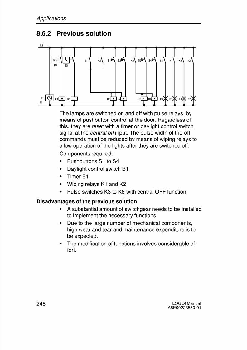
8/10/2019 0900766b805c2bc6
http://slidepdf.com/reader/full/0900766b805c2bc6 260/341
LOGO! ManualA5E00228550-01
248
8.6.2 Previous solution
B1
L1
N
E1
E1
lx> K6
E5
K5
E4
K4
E3
K3
E2K3 K4 K5 K6
S1 S2 S3 S4
K1 K2
K2K2K1
The lamps are switched on and off with pulse relays, bymeans of pushbutton control at the door. Regardless ofthis, they are reset with a timer or daylight control switchsignal at the central off input. The pulse width of the offcommands must be reduced by means of wiping relays toallow operation of the lights after they are switched off.
Components required:
Pushbuttons S1 to S4
Daylight control switch B1 Timer E1
Wiping relays K1 and K2
Pulse switches K3 to K6 with central OFF function
Disadvantages of the previous solution
A substantial amount of switchgear needs to be installedto implement the necessary functions.
Due to the large number of mechanical components,high wear and tear and maintenance expenditure is tobe expected.
The modification of functions involves considerable ef-fort.
Applications

8/10/2019 0900766b805c2bc6
http://slidepdf.com/reader/full/0900766b805c2bc6 261/341
249LOGO! ManualA5E00228550-01
8.6.3 Luminous row control system with
LOGO! 230RC
L1 N I1 I3 I6 I7 I8
Q1 Q2 Q3 Q4
L1
NI2 I3 I4
B1
lx<
Luminous
row 1
I5
Luminous
row 2
Luminous
row 3
Luminous
row 4
S1 S2 S3 S4
I1 I3I1 I3I4 I5I1 I2 I3I1 I2 I3I1 I2 I3I1 I2 I3
1 2 1 2 1 2 1 2
Components used
S1 to S4 (make contact) momentary pushbutton
B1 (make contact) daylight control switch
Applications

8/10/2019 0900766b805c2bc6
http://slidepdf.com/reader/full/0900766b805c2bc6 262/341

8/10/2019 0900766b805c2bc6
http://slidepdf.com/reader/full/0900766b805c2bc6 263/341
251LOGO! ManualA5E00228550-01
8.7 Service water pump
The use of rainwater as an addition to the drinking water
supply is gaining importance in the domestic housing area.This saves money and helps to protect the environment.For example, rainwater can be used for:
Washing clothes
Irrigation system for gardens
Watering indoor plants
Car wash
Toilet flushing installations
The sketch below illustrates how such a rainwater utiliza-tion system is operated:
Õ Õ Õ
Õ Õ Õ
Õ Õ Õ
Š Š Š
Š Š Š
Î Î Î
Î Î Î
Î Î Î
Î Î Î
Î Î Î
Î Î Î
Dry-run protection On
Drinking water supply OnDry-run protection Off
Drinking water supply Off
PumpPressure tank
Pressure switch
S1
Õ Õ Õ
Õ Õ Õ
S2
S3
S4
M1Rainwaterreservoir
Service waterconnection
Control in thedistribution box
Drinking water supply lineK4Rainwatersupply line
The rainwater is collected in a reservoir. From the reservoir,a pumping station supplies a respective line system. Fromthere it can be tapped in the same way as normal drinkingwater. If the reservoir should run dry it can be topped upwith drinking water.
Applications

8/10/2019 0900766b805c2bc6
http://slidepdf.com/reader/full/0900766b805c2bc6 264/341
LOGO! ManualA5E00228550-01
252
8.7.1 Requirements for a control system of a service
water pump
Service water must be available at all times. In case ofemergency, the control system must automaticallyswitch over to drinking water supply.
When switching over to the drinking water supply, theingress of rainwater into the drinking water system mustbe prevented.
The service water pump may not be switched on if thereservoir has run low of rainwater (dry-run protection).
8.7.2 Previous solution
K1 K2
K3
Pump Tracking time
S1
K3
S4 K3
Dry-runprotection
Auxiliary circuit
L1
N
K4
S3 K4
Drinking watersupply line
p<K2
S3 S2
Y1
The pump and a solenoid valve are controlled by means ofa pressure switch and 3 float switches, which are installedin the rainwater reservoir. The pump must be switched on
when the pressure level in the boiler drops below minimum.After the operating pressure is reached, the pump isswitched off again after a tracking time of a few secondshas expired. The tracking time prevents oscillation of thewater pump if water is drawn off over a longer period oftime.
Applications

8/10/2019 0900766b805c2bc6
http://slidepdf.com/reader/full/0900766b805c2bc6 265/341
253LOGO! ManualA5E00228550-01
8.7.3 Service water pump system with
LOGO! 230RC
L1 N I4 I5 I6 I7 I8
Q1 Q2 Q3 Q4
K1 Y1
Pump
S4S3
L1
N
S1
S2p<
Drinking water supply line
I1 I2 I3
1 2 1 2 1 2 1 2
Apart from the LOGO!, all you need is a pressure switchand the float switches to control the pump. If you are usinga 3-phase AC motor, you must use a contactor relay toswitch the pump. For single-phase AC pump systems youmust provide a contactor relay if the power consumption ofthe AC motor exceeds the capacity of the output relay Q1.The power consumption of a solenoid valve is usually lowenough to allow direct controlling.
K1 contactor relay
Y1 solenoid valve
S1 (make contact) pressure switch
S2 (make contact) float switch
S3 (break contact) float switch
S4 (break contact) float switch
Applications

8/10/2019 0900766b805c2bc6
http://slidepdf.com/reader/full/0900766b805c2bc6 266/341
LOGO! ManualA5E00228550-01
254
Block diagram of the LOGO! solution
I2
Float switch for drin-king water supply ON
Drinking watersupply line
Q2
Float switch for drinking water supply OFF
I1Pressureswitch
I3
Float switch for dry-run protection ON I4
Float switch for dry-run protection OFF
x
T = 20 s x
Pump
Q1
I3
8.7.4 Special features and expansions
The block diagram shows how you can interconnect thepump controls and the solenoid valve. The layout corre-sponds with the circuit diagram. You also have the option tointegrate further functions for specific applications, which
can only be implemented in a conventional circuitry by add-ing further switchgear, e.g.:
Enabling the pump at specific times
Indication of imminent or existing water shortage
Reporting of system faults
Applications

8/10/2019 0900766b805c2bc6
http://slidepdf.com/reader/full/0900766b805c2bc6 267/341

8/10/2019 0900766b805c2bc6
http://slidepdf.com/reader/full/0900766b805c2bc6 268/341
LOGO! ManualA5E00228550-01
256
On the Web you can also find descriptions and the corre-sponding circuit diagrams of the applications. You can readthese *.pdf files with the Adobe AcrobatReader. If you haveinstalled LOGO!Soft Comfort on your computer, you cansimply click the disk icon to download the relevant circuitprograms, which you can then adapt to suit your applicationand download to the LOGO! directly via the PC cable.
Benefits of LOGO!
LOGO! is a particularly useful feature
For replacing auxiliary switchgear with the integratedLOGO! functions
For saving wiring and installation work - becauseLOGO! keeps the wiring ”in its head”.
For reducing space requirements for components in thecontrol cabinet/distribution box. A smaller control cabi-net/distribution box may provide sufficient space.
For adding or changing functions, without having toinstall additional switchgear or change the wiring.
For offering your customers new, additional functions fordomestic and commercial housing installations. Exam-ples:
– Domestic security systems: LOGO! switches on alamp at regular intervals or opens and closes theshutters while you are on holiday.
– Central heating: LOGO! runs the circulation pumponly when water or heating is actually required.
– Refrigerating systems: LOGO! can defrost refrigerat-ing systems at regular intervals to save energy costs.
– You can illuminate aquaria and terraria on a time-de-pendent basis.
Last not least you can:
Use commonly available switches and pushbuttons,which makes it easy to install a domestic system.
Connect LOGO! directly to your domestic installation;the integrated power supply makes it possible.
Applications

8/10/2019 0900766b805c2bc6
http://slidepdf.com/reader/full/0900766b805c2bc6 269/341
257LOGO! ManualA5E00228550-01
Do you want more Info?
For more information about LOGO!, see our web page(see the preface for the URL).
Do you have any suggestions?
There are definitely many more useful applications for theLOGO! . If you know of one, why not write to us? We willcollect all the suggestions made and distribute as many ofthem as we can. No matter whether your LOGO! circuit isparticularly complex or simple, simply write to us. We shallbe delighted to receive all your suggestions.
Write to:Siemens AGA&D AS SM MAPO box 48 48
D-90327 Nuremberg
Applications

8/10/2019 0900766b805c2bc6
http://slidepdf.com/reader/full/0900766b805c2bc6 270/341

8/10/2019 0900766b805c2bc6
http://slidepdf.com/reader/full/0900766b805c2bc6 271/341
259LOGO! ManualA5E00228550-01
A Technical data
A.1 General technical data
Criterion Tested in accor-dance with
Values
LOGO!Basic:
Dimensions (WxHxD) 72 x 90 x 55 mm
Weight Approx. 190 g
Installation on a 35 mm profile rail4 module widthsor wall mounting
LOGO! expansionmodule:
Dimensions (WxHxD) 36 x 90 x 55 mm
Weight Approx. 90 g
Installation on a 35 mm profile rail4 module widthsor wall mounting
Climatic conditions
Ambient temperatureHorizontal installation
Low temperature toIEC 60068-2-1
p0 ... 55 C
Vertical installationg temperature
toIEC 60068-2-2
0 ... 55 C
Storage/shipping –- 40 C ... +70 C
Relative humidity IEC 60068-2-30 From 10 to 95 %no condensation
Air pressure 795 ... 1080 hPa
Pollutants IEC 60068-2-42IEC 60068-2-43
SO2 10 cm3 /m3,4 days
H2S 1 cm3 /m3,4 days

8/10/2019 0900766b805c2bc6
http://slidepdf.com/reader/full/0900766b805c2bc6 272/341
LOGO! ManualA5E00228550-01
260
Criterion ValuesTested in accor-dance with
Ambient mechanical conditions
Protection mode IP20Vibrations: IEC 60068-2-6 5 ... 9 Hz (constant
amplitude 3.5 mm)
9 ... 150 Hz (constantacceleration 1 g)
Shock IEC 60068-2-27 18 shocks(half-sine wave15g/11 ms)
Drop IEC 60068-2-31 Drop height 50 mm
Free fall (packaged) IEC 60068-2-32 1 mElectromagnetic compatibility (EMC)
Noise emission EN 55011/AEN 55022/B
EN 50081-1(domestic area)
Limit class B group 1
Electrostatic discharge IEC 61000-4-2
Severity 3
8 kV air discharge
6 kV contact discharge
Electromagnetic fields IEC 61000-4-3 Field strength 10 V/m
HF currents on cables andcable shielding
IEC 61000-4-6 10 V
Burst pulses IEC 61000-4-4Severity 3
2 kV (supply and sig-nal lines)
High-energy surge pulse(applies only toLOGO! 230 ...)
IEC 61000-4-5Severity 3
1 kV (power lines)symmetrical
2 kV (power lines)asymmetrical
Safety to IEC / VDEClearance and creepagedistance rating
IEC 60664,IEC 61131-2,EN 50178cULus to UL 508,CSA C22.2 No.142With LOGO!230 R/RC,also VDE 0631
Fulfilled
Insulation strength IEC 61131-2 Fulfilled
Technical data

8/10/2019 0900766b805c2bc6
http://slidepdf.com/reader/full/0900766b805c2bc6 273/341
261LOGO! ManualA5E00228550-01
A.2 Technical data: LOGO! 230...
and LOGO! DM8 230R
LOGO! 230 RCLOGO! 230 RCo
LOGO! DM8 230R
Power supply
Input voltage 115...240 V AC/DC 115...240 V AC/DC
Permissible range 85 ... 265 V AC100 ... 253 V DC
85 ... 265 V AC100 ... 253 V DC
Permissible mains frequency 47 ... 63 Hz 47 ... 63 Hz
Power consumption
115 V AC 10 ...40 mA 10 ... 30 mA
240 V AC 10 ... 25 mA 10 ... 20 mA
115 V DC 5 ... 25 mA 5 ... 15 mA
240 V DC 5 ... 15 mA 5 ... 10 mA
Voltage failure buffering
p p 5 typ. ms typ. ms
p p yp. ms yp. ms
Power loss at
115 V AC 1.1 ... 4.6 W 1.1 ... 3.5 W
240 V AC 2.4 ... 6.0 W 2.4 ... 4.8 W
115 V DC 0.5 ... 2.9 W 0.5 ... 1.8 W
240 V DC 1.2 ... 3.6 W 1.2 ... 2.4 W
Backup of the real-time clockat 25 C
typ. 80 h
Accuracy of the real-timeclock
typ. 2 s / day
Digital inputs
Number 8 4
Electrical isolation No No
Technical data

8/10/2019 0900766b805c2bc6
http://slidepdf.com/reader/full/0900766b805c2bc6 274/341
LOGO! ManualA5E00228550-01
262
LOGO! DM8 230RLOGO! 230 RCLOGO! 230 RCo
Input voltage L1
Signal 0
Signal 1
Signal 0
Signal 1
< 40 V AC
> 79 V AC
< 30 V DC
> 79 V DC
< 40 V AC
> 79 V AC
< 30 V DC
> 79 V DC
Input current at
Signal 0
< 0.03 mA < 0.03 mA
gna > . m > . m
Delay time at
0 to 1 typ. 50 ms typ. 50 ms
1 to 0 typ. 50 ms typ. 50 ms
Line length (unshielded) 100 m 100 m
Digital outputs
Number 4 4
Output type Relay outputs Relay outputs
Electrical isolation Yes Yes
In groups of 1 1
Control of a digital input Yes Yes
Continuous current Ith max. 10 A per relay max. 5 A per relay
Incandescent lamp load
(25000 switching cycles) at230/240 V AC
115/120 V AC
1000 W
500 W
1000 W
500 W
Fluorescent tubes with ballast(25000 switching cycles)
10 x 58 W(at 230/240 V AC)
10 x 58 W(at 230/240 V AC)
Fluorescent tubes, conven-tionally compensated (25000switching cycles)
1 x 58 W(at 230/240 V AC)
1 x 58 W(at 230/240 V AC)
Technical data

8/10/2019 0900766b805c2bc6
http://slidepdf.com/reader/full/0900766b805c2bc6 275/341
263LOGO! ManualA5E00228550-01
LOGO! DM8 230RLOGO! 230 RCLOGO! 230 RCo
Fluorescent tubes, uncom-
pensated (25000 switchingcycles)
10 x 58 W (at
230/240 V AC)
10 x 58 W (at
230/240 V AC)
Short circuit-proof cos 1 Power protectionB16600A
Power protectionB16600A
Short-circuit proof cos0.5 to 0.7
Power protectionB16900A
Power protectionB16900A
Derating none; across theentire temperaturerange
none; across theentire temperaturerange
Parallel output circuits forpower increase
Not permitted Not permitted
Protection of output relay(if desired)
max. 16 A,characteristic B16
max. 16 A,characteristic B16
Switching rate
Mechanical 10 Hz 10 HzOhmic load/lamp load 2 Hz 2 Hz
Inductive load 0.5 Hz 0.5 Hz
Technical data

8/10/2019 0900766b805c2bc6
http://slidepdf.com/reader/full/0900766b805c2bc6 276/341
LOGO! ManualA5E00228550-01
264
A.3 Technical data: LOGO! 24... and
LOGO! DM8 24
LOGO! 24LOGO! 24o
LOGO! DM8 24
Power supply
Input voltage 24 V DC 24 V DC
Permissible range 20.4 ... 28.8 V DC 20.4 ... 28.8 V DC
Reverse polarity protection Yes Yes
Permissible mains frequencyPower consumption from24 V DC
30 ... 55 mA
0.3 A per output
30 ... 45 mA
0.3 A per output
Voltage failure buffering
Power loss at 24 V 0.7 ... 1.3 W 0.8 ... 1.1 W
Backup of the real-time clockat 25 C
Accuracy of the real-timeclock
Digital inputs
Number 8 4
Electrical isolation No No
Input voltage L+ L+
Signal 0 < 5 V DC < 5 V DC
Signal 1 > 8 V DC > 8 V DC
Technical data

8/10/2019 0900766b805c2bc6
http://slidepdf.com/reader/full/0900766b805c2bc6 277/341
265LOGO! ManualA5E00228550-01
LOGO! DM8 24LOGO! 24LOGO! 24o
Input current at
Signal 0 < 1.0 mA (I1...I6)< 0.05 mA (I7, I8)
< 1.0 mA
Signal 1 > 1.5 mA (I1... I6)> 0.1 mA (I7, I8)
> 1.5 mA
Delay time at
0 to 1 typ. 1.5 ms (I1...I4)
<1.0 ms (I5, I6)
typ. 300 ms (I7,I8)
typ. 1.5 ms
1 to 0 typ. 1.5 ms (I1...I4)
<1.0 ms (I5, I6)
typ. 300 ms (I7,I8)
typ. 1.5 ms
Line length (unshielded) 100 m 100 m
Analog inputs
Number 2 (I7 and I8)
Range 0 ... 10 V DCinput impedance76 k
max. input voltage 28.8 V DC
Line length (shielded andtwisted)
10 m
Digital outputs
Number 4 4
Output type Transistor,current-sourcing
Transistor,current-sourcing
Electrical isolation No No
In groups of
Control of a digital input Yes Yes
Output voltage Supply voltage Supply voltage
Output current max. 0.3 A max. 0.3 A
Technical data

8/10/2019 0900766b805c2bc6
http://slidepdf.com/reader/full/0900766b805c2bc6 278/341
LOGO! ManualA5E00228550-01
266
LOGO! DM8 24LOGO! 24LOGO! 24o
Continuous current Ith
Incandescent lamp load(25000 switching cycles) at
Fluorescent tubes with ballast(25000 switching cycles)
Fluorescent tubes, conven-tionally compensated (25000switching cycles)
Fluorescent tubes, uncom-
pensated (25000 switchingcycles)
Short circuit-proof and over-load-proof
Yes Yes
Short-circuit current limitation Approx. 1 A Approx. 1 A
Derating none; across theentire temperaturerange
none; across theentire temperaturerange
Short circuit-proof cos 1
Short-circuit proof cos 0.5 to0.7
Parallel output circuit forpower increase
Not permitted Not permitted
Protection of output relay (ifdesired)
Switching rateMechanical
Electrical 10 Hz 10 Hz
Ohmic load/lamp load 10 Hz 10 Hz
Inductive load 0.5 Hz 0.5 Hz
Technical data

8/10/2019 0900766b805c2bc6
http://slidepdf.com/reader/full/0900766b805c2bc6 279/341

8/10/2019 0900766b805c2bc6
http://slidepdf.com/reader/full/0900766b805c2bc6 280/341
LOGO! ManualA5E00228550-01
268
LOGO! DM8 24 RLOGO! 24RCLOGO! 24RCo
Input current at
Signal 0 < 1.0 mA < 1.0 mA
Signal 1> 2.5 mA > 2.5 mA
Delay time at
0 to 1 typ. 1,5 ms typ. 1.5 ms
1 to 0 typ. 15 ms typ. 15 ms
Line length (unshielded) 100 m 100 m
Analog inputs
Number
Range
max. Input voltage
Digital outputs
Number 4 4
Output type Relay outputs Relay outputs
Electrical isolation Yes Yes
In groups of 1 1
Control of a digital input Yes Yes
Output voltage
Output current
Continuous current Ith max. 10 A per relay max. 5 A per relay
Incandescent lamp load(25000 switching cycles) at
1000 W 1000 W
Fluorescent tubes with ballast(25000 switching cycles)
10 x 58 W 10 x 58 W
Technical data

8/10/2019 0900766b805c2bc6
http://slidepdf.com/reader/full/0900766b805c2bc6 281/341
269LOGO! ManualA5E00228550-01
LOGO! DM8 24 RLOGO! 24RCLOGO! 24RCo
Fluorescent tubes, conven-
tionally compensated (25000switching cycles)
1 x 58 W 1 x 58 W
Fluorescent tubes, uncom-pensated (25000 switchingcycles)
10 x 58 W 10 x 58 W
Short circuit-proof and over-load-proof
Short-circuit current limitation
Derating none; across theentire temperaturerange
none; across theentire temperaturerange
Short circuit-proof cos 1 Power protectionB16,600A
Power protectionB16,600A
Short-circuit proof cos 0.5 to0.7
Power protectionB16,
900A
Power protectionB16,
900AParallel output circuits forpower increase
Not permitted Not permitted
Protection of output relay (ifdesired)
max. 16 A,characteristic B16
max. 16 A,characteristic B16
Switching rate
Mechanical 10 Hz 10 Hz
Electrical
Ohmic load/lamp load 2 Hz 2 Hz
Inductive load 0.5 Hz 0.5 Hz
Technical data

8/10/2019 0900766b805c2bc6
http://slidepdf.com/reader/full/0900766b805c2bc6 282/341
LOGO! ManualA5E00228550-01
270
A.5 Technical data: LOGO! 12/24... and
LOGO! DM8 12/24R
LOGO! 12/24RCLOGO! 12/24RCo
LOGO! DM812/24R
Power supply
Input voltage 12/24 V DC 12/24 V DC
Permissible range 10.8 ... 28.8 V DC 10.8 ... 28.8 V DC
Reverse polarity protection Yes Yes
Power consumption 12 V DC
24 V DC
30 ... 140 mA
20 ... 75 mA
30 ... 140 mA
20 ... 75 mA
Voltage failure buffering
12 V DC
24 V DC typ. 2 ms
typ. 5 ms
typ. 2 ms
typ. 5 ms
Power loss
12 V DC
24 V DC
0.3 ... 1.7 W
0.4 ... 1.8 W
0.3 ... 1.7 W
0.4 ... 1.8 W
Backup of the real-time clockat 25 C
typ. 80 h
Accuracy of the real-timeclock
typ.2 s / day
Electrical isolation No No
Digital inputs
Number 8 4
Electrical isolation No No
Input voltage L+
Signal 0 < 5 V DC < 5 V DC
Signal 1 > 8 V DC > 8 V DC
Technical data

8/10/2019 0900766b805c2bc6
http://slidepdf.com/reader/full/0900766b805c2bc6 283/341
271LOGO! ManualA5E00228550-01
LOGO! DM812/24R
LOGO! 12/24RCLOGO! 12/24RCo
Input current at
Signal 0 < 1.0 mA (I1...I6)< 0.05 mA (I7, I8)
< 1.0 mA
Signal 1 > 1.5 mA (I1... I6)> 0.1 mA (I7, I8)
> 1.5 mA
Delay time at
0 to 1 typ. 1.5 ms
<1.0 ms (I5, I6)
typ. 300 ms (I7,I8)
typ. 1.5 ms
1 to 0 typ. 1.5 ms
<1.0 ms (I5, I6)
typ. 300 ms (I7,I8)
typ. 1.5 ms
Line length (unshielded) 100 m 100 m
Analog inputs
Number 2 (I7, I8)
Range 0 ... 10 V DCinput impedance76 k
max. Input voltage 28.8 V DC
Line length (shielded andtwisted)
10 m
Digital outputs
Number 4 4Output type Relay outputs Relay outputs
Electrical isolation Yes Yes
In groups of 1 1
Control of a digital input Yes Yes
Output voltage
Output current
Technical data

8/10/2019 0900766b805c2bc6
http://slidepdf.com/reader/full/0900766b805c2bc6 284/341
LOGO! ManualA5E00228550-01
272
LOGO! DM812/24R
LOGO! 12/24RCLOGO! 12/24RCo
Continuous current Ith (per
terminal)
max. 10 A per relay max. 5 A per relay
Incandescent lamp load(25000 switching cycles) at
1000 W 1000 W
Fluorescent tubes with ballast(25000 switching cycles)
10 x 58 W 10 x 58 W
Fluorescent tubes, conven-tionally compensated (25000switching cycles)
1 x 58 W 1 x 58 W
Fluorescent tubes, uncom-pensated (25000 switchingcycles)
10 x 58 W 10 x 58 W
Short circuit-proof and over-load-proof
Short-circuit current limitation
Derating none; across theentire temperature
range
none; across theentire temperature
rangeShort circuit-proof cos 1 Power protection
B16600A
Power protectionB16600A
Short-circuit proof cos 0.5 to0.7
Power protectionB16900A
Power protectionB16900A
Parallel output circuits for
power increase
Not permitted Not permitted
Protection of output relay (ifdesired)
max. 16 A,characteristic B16
max. 16 A,characteristic B16
Switching rate
Mechanical 10 Hz 10 Hz
Electrical
Ohmic load/lamp load 2 Hz 2 Hz
Inductive load 0.5 Hz 0.5 Hz
Technical data

8/10/2019 0900766b805c2bc6
http://slidepdf.com/reader/full/0900766b805c2bc6 285/341
273LOGO! ManualA5E00228550-01
A.6 Switching capacity and service life of the
relay outputs
Ohmic load
Switching cycles/million
Switched current/A
0.1
0.2
0.3
0.4
0.5
2 4 6 8 10
Maximum 10 AMaximum 10 AMaximum 10 A
Maximum 0.2 AMaximum 0.1 A
12/24 V AC/DC115/120 V AC230/240 V AC
120 V DC240 V DC
Figure A Switching capacity and service life of the contacts with ohmicload (heating)
Inductive load
Switching cycles/million
Switched current/A
0.1
0.2
0.3
0.4
0.5
321
0.6
0.7
0.8
0.9
1.0Maximum 2 AMaximum 3 AMaximum 3 A
Maximum 0.2 AMaximum 0.1 A
12/24 V AC/DC115/120 V AC230/240 V AC
120 V DC240 V DC
Figure B Switching capacity and service life of the contacts with high in-ductive load to IEC 947-5-1 DC 13/AC 15 (contactors, solenoidcoils, motors)
Technical data

8/10/2019 0900766b805c2bc6
http://slidepdf.com/reader/full/0900766b805c2bc6 286/341
LOGO! ManualA5E00228550-01
274
A.7 Technical data: LOGO! AM 2
LOGO! AM 2
Power supply
Input voltage 12/24 V DC
Permissible range 10.8 ... 28.8 V DC
Power consumption 25 ... 50 mA
Voltage failure buffering typ. 5 ms
Power loss at
12 V 24 V
0.3 ... 0.6 W0.6 ... 1.2 W
Electrical isolation No
Reverse polarity protection Yes
Ground terminal for connecting ground and shielding ofthe analog measuring line.
Analog inputs
Number 2
Type Unipolar
Input range 0 ... 10 V DC (input impedance 76 k)or0 ... 20 mA (input impedance <250 )
Resolution 10 bit, normalized to 0 ... 1000
Cycle time for analog valuegeneration
50 ms
Electrical isolation No
Line length (shielded andtwisted)
10 m
Encoder supply voltage none
Error limit +/– 1.5 %
Interference frequency suppres-sion
55 Hz
Technical data

8/10/2019 0900766b805c2bc6
http://slidepdf.com/reader/full/0900766b805c2bc6 287/341

8/10/2019 0900766b805c2bc6
http://slidepdf.com/reader/full/0900766b805c2bc6 288/341
LOGO! ManualA5E00228550-01
276
LOGO! AM 2 PT100
Curve linearization No
Measuring current Ic 1.1 mA
Measurement rate depends on the installation
typical: 50 ms
Resolution 0.25 C
Error limits
C ... +200 C
C ... +200 C
of the final measured value:
+/– 1.0 %
+/– 1.5 %
Electrical isolation NoCable length (shielded) 10 m
Interference frequency suppres-sion
55 Hz
Technical data

8/10/2019 0900766b805c2bc6
http://slidepdf.com/reader/full/0900766b805c2bc6 289/341
277LOGO! ManualA5E00228550-01
A.9 Technical data: LOGO!Power 12 V
LOGO! Power 12 V is a primary-switched power supply unit
for LOGO! devices. Two current ranges are available.
LOGO! Power12 V / 1.9 A
LOGO! Power12 V / 4.5 A
Input data
Input voltage 120 ... 230 V AC
Permissible range 85 ... 264 V AC
Permissible mains frequency 47 ... 63 Hz
Voltage failure buffering > 40 ms (at 187 V AC)
Input current 0.3 ... 0.18 A 0.73 ... 0.43 A
Make current (25C) 15 A 30 A
Device protection Internal
Recommended circuitbreaker (IEC 898) in mainsline
> 6 A characteristic D> 10 A characteristic C
Output data
Output voltage
Overall tolerance
Adjustment range
Residual ripple
12 V DC
+/–3 %
11.1 ... 12.9 V DC
< 200 mVpp
Output current
Overcurrent limiting
1.9 A
2.4 A
4.5 A
4.5 A
Efficiency 80 %
Parallel circuit for power in-crease
Yes
Electromagnetic compatibility
Interference suppression EN 50081-1, EN 55022 Class B
Interference immunity EN 50082-2
Technical data

8/10/2019 0900766b805c2bc6
http://slidepdf.com/reader/full/0900766b805c2bc6 290/341
LOGO! ManualA5E00228550-01
278
LOGO! Power12 V / 4.5 A
LOGO! Power12 V / 1.9 A
Safety
Electrical isolation, primary/ secondary
Yes, SELV (to EN 60950/VDE 0805)
Safety class II (to IEC 536/VDE 0106 T1)
Protection mode IP 20 (to EN 60529/VDE 470 T1)
CE marking
UL/CSA certification
FM approval
Yes
Yes; UL 508 / CSA 22.2
In preparation
General details
Ambient temperature range –20 ... +55C, natural convection
Storage and shipping tempe-rature
–40 ... +70C
Connections at input One terminal (1 x 2.5 mm2 or 2 x 1.5 mm2)per L1 and N
Connections at output Two terminals (1x.2.5 mm2 or
2 x 1.5 mm2
) per L+ and MInstallation On 35 mm DIN rail, snap-on
Dimensions in mm (WxHxD) 72 x 80 x 55 126 x 90 x 55
Approx. weight 0.2 kg 0.4 kg
Technical data

8/10/2019 0900766b805c2bc6
http://slidepdf.com/reader/full/0900766b805c2bc6 291/341
279LOGO! ManualA5E00228550-01
A.10 Technical data: LOGO!Power 24 V
LOGO! Power 24 V is a primary-switched power supply
module for LOGO! devices. Two current ranges are avail-able.
LOGO! Power24 V / 1.3 A
LOGO! Power24 V / 2.5 A
Input data
Input voltage 120 ... 230 V AC
Permissible range 85 ... 264 V AC
Permissible mains frequency 47 ... 63 Hz
Voltage failure buffering 40 ms (at 187 V AC)
Input current 0.48 ... 0.3 A 0.85 ... 0.5 A
Inrush current (25C) < 15 A < 30 A
Device protection Internal
Recommended circuitbreaker (IEC 898) in mains
line
> 6 A characteristic D> 10 A characteristic C
Output data
Output voltage
Overall tolerance
Adjustment range
Residual ripple
24 V DC
+/- 3 %
22.2 ... 25.8 V DC
< 250 mVpp
Output current
Overcurrent limiting
1.3 A
1.6 A
2.5 A
2.8 A
Efficiency > 80 %
Parallel circuit for power in-crease
Yes
Electromagnetic compatibility
Interference suppression EN 50081-1, EN 55022 Class B
Interference immunity EN 50082-2
Technical data

8/10/2019 0900766b805c2bc6
http://slidepdf.com/reader/full/0900766b805c2bc6 292/341
LOGO! ManualA5E00228550-01
280
LOGO! Power24 V / 2.5 A
LOGO! Power24 V / 1.3 A
Safety
Electrical isolation, primary/ secondary
Yes, SELV (to EN 60950/VDE 0805)
Safety class II (to IEC 536/VDE 0106 T1)
Protection mode IP 20 (to EN 60529/VDE 470 T1)
CE marking
UL/CSA certification
FM approval
Yes
Yes; UL 508 / CSA 22.2
Yes; Class I, Div. 2, T4
General details
Ambient temperature range –20 ... +55C, natural convection
Storage and shipping tempe-rature
–40 ... +70C
Connections at input One terminal (1 x. 2.5 mm2 or 2 x 1.5 mm2)per L1 and N
Connections at output Two terminals (1x.2.5 mm2
or 2 x 1.5 mm2
) per L+ and MInstallation On 35 mm DIN rail, snap-on
Dimensions in mm (WxHxD) 72 x 80 x 55 126 x 90 x 55
Approx. weight 0.2 kg 0.4 kg
Technical data

8/10/2019 0900766b805c2bc6
http://slidepdf.com/reader/full/0900766b805c2bc6 293/341
281LOGO! ManualA5E00228550-01
A.11 Technical data: LOGO! Contact 24/230
LOGO! Contact 24 and LOGO! Contact 230 are switching
modules for direct switching of ohmic loads up to 20 Ampsand motors up to 4 kW (without noise emission, hum-free).
LOGO!Contact 24
LOGO!Contact 230
Operating voltage 24 V DC 230 V AC;50/60 Hz
Switching capacity
Utilization category AC-1: Switching ofohmic loads at 55C
Operating current at 400 V
Output with three-phase loads at 400 V
20 A
13 kW
Utilization category AC-2, AC-3: Motorwith slip ring induction/cage armature
Operating current at 400 V
Output with three-phase loads at 400 V
8.4 A
4 kW
Short-circuit protection:Assignment type 1
Assignment type 2
25 A
10 A
Connecting leads Fine-wire with wire end ferrules
Solid wire
2 x (0.75 to 2.5) mm2
2 x (1 to 2.5) mm2
1 x 4 mm2
Dimensions (WxHxD) 36 x 72 x 55
Ambient temperature -25 ... +55C
Storage temperature -50 ... +80C
Technical data

8/10/2019 0900766b805c2bc6
http://slidepdf.com/reader/full/0900766b805c2bc6 294/341
LOGO! ManualA5E00228550-01
282
Technical data

8/10/2019 0900766b805c2bc6
http://slidepdf.com/reader/full/0900766b805c2bc6 295/341
283LOGO! ManualA5E00228550-01
B Determining the cycle time
The program cycle is the complete execution of the circuit
program, that is, primarily the reading in of the inputs, theprocessing of the circuit program and the subsequent read-ing out of the outputs. The cycle time is the time required toexecute a circuit program once in full.
The time required for a program cycle can be determinedusing a short test program. This test program is created inLOGO! and returns a value during its execution in parame-ter assignment mode from which the current cycle time isderived.
Test program
1. Create the test program by linking an output to a thresh-old trigger and connecting the trigger input with an in-verted flag.
ParQx
B1
Output Qx orother flag MxM1
M1M1
1B2
2. Configure the threshold trigger as shown below. A pulseis generated in each program cycle due to the invertedflag. The trigger interval is set to 2 seconds.

8/10/2019 0900766b805c2bc6
http://slidepdf.com/reader/full/0900766b805c2bc6 296/341
LOGO! ManualA5E00228550-01
284
B1 1+On =1000
Off=0000
B1 2G_T=02:00s
Press
3. Now start the circuit program and switch LOGO! to pa-rameter assignment mode. In this mode, view the triggerparameters.
B1On =1000
Off =0000fa =0086
fa= total of measured pulses per timeb
4. The reciprocal value of fa is equivalent to the LOGO!execution time of the current circuit program in its me-mory.
1/fa = cycle time in s
ExplanationThe inverted flag block changes its output signal at eachprogram execution. Thus, one logic level (high or low) widthis exactly equivalent to the length of one cycle. Hence, aperiod lasts 2 cycles.
The threshold trigger indicates the ratio of periods per 2seconds, which results in the ratio of cycles per second.
Edge transition of the inverted flag at
each circuit program execution
Cycletime
Period
1 period = 1 pulse = 2 cycles
Determining the cycle

8/10/2019 0900766b805c2bc6
http://slidepdf.com/reader/full/0900766b805c2bc6 297/341
285LOGO! ManualA5E00228550-01
C LOGO! without display
Because some specific applications do not require operator
control and monitoring units such as buttons or a display,we provide the LOGO! 12/24RCo, LOGO! 24o,LOGO! 24RCo and LOGO! 230RCo versions without dis-play.
View of a LOGO! 230RCo, for example:
I4 I5 I6
Q1 Q2 Q3 Q4
L1 N
RUN/STOP
I7 I8I1 I2 I3I1 I2 I3I1 I2 I3I1 I2 I3I1 I2 I3I1 I2 I3I1 I2 I3I1 I2 I3
1 2 1 2 1 2 1 2
Less is definitely more!
The versions without display offer you the following bene-
fits:
Even more cost-effective without the operating element.
Requires less switch cabinet space than conventionalhardware.
Substantial benefits with regard to flexibility and primecosts compared to stand-alone electronic switchgear.
Of advantage even for applications in which merely twoor three conventional switching devices can be re-
placed.
Very easy to use.
Access protected.
Compatible to LOGO! versions with display.
Offers the option to read data by means of LOGO!SoftComfort.

8/10/2019 0900766b805c2bc6
http://slidepdf.com/reader/full/0900766b805c2bc6 298/341
LOGO! ManualA5E00228550-01
286
Creating a circuit program without operator panel
There are two ways to create a circuit program for a LOGO!without display:
You create the circuit program with LOGO!Soft Comforton your PC and then download it to the LOGO!(see Chapter 7).
You download the circuit program from a LOGO! pro-gram module (card) to your LOGO! without display(see Chapter 6).
Operating characteristics
LOGO! is ready for operation when power is switched on.
Switching off a LOGO! without display is equivalent to dis-connecting the power supply, e.g. as if you were removingthe plug.
The circuit program of LOGO!...o versions can not be star-ted or stopped by means of buttons. This is why theLOGO!...o versions have other startup characteristics:
Startup characteristics
If there is no circuit program in the LOGO! or on the in-
serted program module (card), LOGO! remains in STOP.
If there is a valid circuit program in LOGO! memory, theLOGO! automatically switches from STOP to RUN whenpower is switched on.
The circuit program on an inserted program module (card)is automatically copied to the LOGO!, immediately afterpower is switched on. The existing circuit program inLOGO! memory is overwritten. The system automatically
changes from STOP to RUN.Provided the PC cable is connected to the LOGO!, you candownload the circuit program to LOGO! and start it bymeans of the LOGO!Soft Comfort PC software(see Chapter 7.1).
LOGO! without display

8/10/2019 0900766b805c2bc6
http://slidepdf.com/reader/full/0900766b805c2bc6 299/341
287LOGO! ManualA5E00228550-01
Operating status indication
Operating states, e.g. Power On, RUN and STOP are indi-cated by an LED on the front hood.
Red LED: Power On/STOP Green LED: Power On/RUN
The red LED is lit after Power On and in all LOGO! statesother than RUN. The green LED is lit when LOGO! is inRUN mode.
Reading current data
LOGO!Soft Comfort (see Chapter 7) provides an online testfor reading the current data of all functions while the sys-
tem is in RUN.
If your LOGO! without display holds a protected programmodule (card), you can not read the current data unlessyou enter the correct password for your the circuit program.The circuit program is otherwise deleted from LOGO! me-mory when you remove the program module (card) to con-nect the PC cable, for example (see Chapter 6.1).
LOGO! without display

8/10/2019 0900766b805c2bc6
http://slidepdf.com/reader/full/0900766b805c2bc6 300/341
LOGO! ManualA5E00228550-01
288
LOGO! without display

8/10/2019 0900766b805c2bc6
http://slidepdf.com/reader/full/0900766b805c2bc6 301/341
289LOGO! ManualA5E00228550-01
D LOGO! menu structure
>Stop
Set Param
Set ClockPrg Name
>Program
Card
Clock
Start
Menu overview
See “Main menu”
Mo 09:00
2003-01-27
See “Start menu“
Press ESC No Program
Circuit program isbusy (RUN)
No Program
Parameter setting (Chapter 5.1.1 cont.)Clock/date setting (Chapter 5.2)Display of the program name
>Program..
Card..
Clock..
Start
>Yes
Parameter assign-ment menu
Main menu (ESC / >Stop)
See “Programming menu”>Edit..
> –>Card
>SetClock
See “Transfer menu”
See “Clock menu”
See “Start menu“>Stop/>Yes
Mo 09:002003-01-27
Programming menu (ESC / >Stop >Program)
>Edit..
>Clear Prg
>Password
>Edit Prg Password?Editing the program
(Chapter 3.6 cont.)
>Edit Name
>Memory?
Editing the programname (Chapter 3.6.4)
Show available memoryspace (Chapter 3.7)
Deleting the program(Chapter 3.6.11)
Input/change of pass-word (Chapter 3.6.5)

8/10/2019 0900766b805c2bc6
http://slidepdf.com/reader/full/0900766b805c2bc6 302/341
LOGO! ManualA5E00228550-01
290
Transfer menu (ESC / >Stop >Card)
Clock menu (ESC / >Stop >Clock)
> –>Card
>Card–>
>CopyProtect
Copying the program from the program mod-ule (card) to LOGO! (Chapter 6.4)
Setting the program/copy protection(Chapter 6.1)
Copying the circuit program from LOGO! to the program module (card) (Chapter 6.3)
Start menu (RUN)
>Set Clock
>S/W Time
>Sync
Setting the summertime/wintertime (Chapter 3.6.12)
Synchronizing the times of LOGO! Basicand expansion modules (Chapter 3.6.13)
Setting the time/date (Chapter 5.2)
Everything
clear?
LOGO!
Mo 09:002003–01–27
Date/time
max. 10 message texts
Inputs
I:
0.. 123456789
1..0123456789
2..01234
Cursor keys
Q:
0.. 123456789
1..0123456
M:
0.. 123456789
1..0123456789
2..01234
ESC+Key
Outputs Flags
Parameter assignment menu
>Stop
Set Param
Set Clock
Prg Name
LOGO! Menu structure

8/10/2019 0900766b805c2bc6
http://slidepdf.com/reader/full/0900766b805c2bc6 303/341
291LOGO! ManualA5E00228550-01
E Order numbers
Table A
Variant Designation Order number
Basic LOGO! 12/24 RC *
LOGO! 24):
LOGO! 24 RC (AC)
LOGO! 230 RC
6ED1052-1MD00-0BA4
6ED1052-1CC00-0BA4
6ED1052-1HB00-0BA4
6ED1052-1FB00-0BA4
Basicwithout display
(pure)
LOGO! 12/24 RCo *
LOGO! 24o *LOGO! 24 RCo (AC)
LOGO! 230 RCo
6ED1052-2MD00-0BA4
6ED1052-2CC00-0BA46ED1052-2HB00-0BA4
6ED1052-2FB00-0BA4
Digital modules LOGO! DM 8 12/24R
LOGO! DM 8 24
LOGO! DM 8 24R
LOGO! DM 8 230R
6ED1055-1MB00-0BA1
6ED1055-1CB00-0BA0
6ED1055-1HB00-0BA0
6ED1055-1FB00-0BA1
Analog modules LOGO! AM 2
LOGO! AM 2 PT100
6ED1055-1MA00-0BA0
6ED1055-1MD00-0BA0
*: Also with analog inputs

8/10/2019 0900766b805c2bc6
http://slidepdf.com/reader/full/0900766b805c2bc6 304/341
LOGO! ManualA5E00228550-01
292
Table B
Accessories Designation Order number
Software LOGO!Soft Comfort V4.0
Upgrade toLOGO!Soft Comfort V4.0
6ED1058-0BA00-0YA0
6ED1058-0CA00-0YE0
Program mod-ule (card)
LOGO! Card 6ED1056-5CA00-0BA0
Switching mod-ules
LOGO!Contact 24 V
LOGO!Contact 230 V
6ED1057–4CA00–0AA0
6ED1057–4EA00–0AA0
Power modules LOGO!Power 12V/1.9A
LOGO!Power 12V/4.5A
LOGO!Power 24V/1.3A
LOGO!Power 24V/2.5A
6EP1321–1SH01
6EP1322–1SH01
6EP1331–1SH01
6EP1332–1SH41
Others PC cable
Manual
6ED1057–1AA00–0BA0
6ED1050–1AA00–0BE5
Order numbers

8/10/2019 0900766b805c2bc6
http://slidepdf.com/reader/full/0900766b805c2bc6 305/341
293LOGO! ManualA5E00228550-01
F Abbreviations
AM Analog module
B1 Block number B1BN Block Number
C LOGO! device designation: integrated clock
CM Communication Module
Cnt Count = Counter input
Co Connector
Dir Direction (of count, for example)
DM Digital ModuleEn Enable = switching on
(clock generators, for example)
Fre Input for frequency signals to be analyzed
GF Basic Functions
Inv Input for inverting the output signal
No Cam (parameter of the timer)
o in LOGO! designations: without display
Par Parameter
R Reset input
R in LOGO! designations: Relay outputs
Ral Reset all = Input for resetting all internal values
S Set (latching relay, for example)
SF Special functions
SU Subunit
T Time = parameter
Trg Trigger (parameter)
0BA4 devices: the latest LOGO! Basic version, described inthis Manual.

8/10/2019 0900766b805c2bc6
http://slidepdf.com/reader/full/0900766b805c2bc6 306/341
LOGO! ManualA5E00228550-01
294
Order numbers

8/10/2019 0900766b805c2bc6
http://slidepdf.com/reader/full/0900766b805c2bc6 307/341
295LOGO! ManualA5E00228550-01
Index

8/10/2019 0900766b805c2bc6
http://slidepdf.com/reader/full/0900766b805c2bc6 308/341
LOGO! ManualA5E00228550-01
296
Index

8/10/2019 0900766b805c2bc6
http://slidepdf.com/reader/full/0900766b805c2bc6 309/341
297LOGO! ManualA5E00228550-01
Index

8/10/2019 0900766b805c2bc6
http://slidepdf.com/reader/full/0900766b805c2bc6 310/341
LOGO! ManualA5E00228550-01
298
Index

8/10/2019 0900766b805c2bc6
http://slidepdf.com/reader/full/0900766b805c2bc6 311/341
299LOGO! ManualA5E00228550-01
Index

8/10/2019 0900766b805c2bc6
http://slidepdf.com/reader/full/0900766b805c2bc6 312/341
LOGO! ManualA5E00228550-01
300
Index

8/10/2019 0900766b805c2bc6
http://slidepdf.com/reader/full/0900766b805c2bc6 313/341
301LOGO! ManualA5E00228550-01
Index

8/10/2019 0900766b805c2bc6
http://slidepdf.com/reader/full/0900766b805c2bc6 314/341
LOGO! ManualA5E00228550-01
302
Index

8/10/2019 0900766b805c2bc6
http://slidepdf.com/reader/full/0900766b805c2bc6 315/341
A5E00324307-01Copyright 2004 by Siemens AG
Produktinformation
07.2004
Produktinformation zum Handbuch LOGO!; ab Ausgabe 06/2003
(A5E00228104-01)
VorbemerkungDiese Produktinformation enthält wichtige Informationen zu LOGO!Sie ist als separater Bestandteil aufzufassen und in Zweifelsfällen in der Verbind-lichkeit anderen Aussagen in Handbüchern und Katalogen übergeordnet.
Diese Produktinformation enthält die Ergänzungen für die LOGO!-Erweiterungs-module DM16 24, DM16 24R und DM16 230R.

8/10/2019 0900766b805c2bc6
http://slidepdf.com/reader/full/0900766b805c2bc6 316/341
2ProduktinformationLOGO!
A5E00324307-01
1.1 Welche Erweiterungsmodule gibt es?
• LOGO! Digitalmodule DM8... gibt es für 12 V DC, 24 V AC/DC und115...240 V AC/DC mit 4 Eingängen und 4 Ausgängen.
• LOGO! Digitalmodule DM16... gibt es für 24 V DC und 115...240 V AC/DC mit8 Eingängen und 8 Ausgängen.
• LOGO! Analogmodule gibt es für 12 V DC und 24 V DC mit 2 Analogeingängenbzw. mit 2 Pt100-Eingängen.
• LOGO! Kommunikationsmodule (CM), wie z.B. Kommunikationsmodul AS-In-terface, das in einer eigenen Dokumentation beschrieben wird.
Digital- und Analogmodule sind in 2 bzw. 4 TE integriert und besitzen jeweils zwei Er-weiterungsschnittstellen, so dass an jedes ein weiteres Modul angeschlossen seinkann.
1.2 So ist LOGO! aufgebaut
L O G O ! E r w e i t e r u n g s m o d u l
( z . B . : D M 1 6 2 4 R )
4
5
Anzeige des ZustandesRUN/STOP
Schieber
3 5
72
9 0
53
6
Mechanische Codierung –Stifte
3
1
2
77 8
7
Erweiterungsschnitt-stelle
1
2
3 Ausgänge
Spannungsversorgung
Eingänge
66
8 Mechanische Codierung –Buchsen
4
Q2
Q6
Q1 Q2
L+ M I2 I3 I4I1
RUN/STOP
Q5 Q8
Q3
I5 I6 I8I7
Q7
Q41 2
1 2 1 2 1 2 1 2
1 2 1 2 1 2
4
5
Symbole
Digitalmodul verfügt über 4 Digitaleingänge und 4 Digitalausgänge
Digitalmodul verfügt über 8 Digitaleingänge und 8 Digitalausgänge

8/10/2019 0900766b805c2bc6
http://slidepdf.com/reader/full/0900766b805c2bc6 317/341
3ProduktinformationLOGO!A5E00324307-01
1.3 Erweiterungsmodule
An LOGO! können folgende Erweiterungsmodule angeschlossen werden:
Symbol Bezeichnung Versorgung Eingänge Ausgänge
LOGO! DM 8 12/24R 12/24 V DC 4 Digital 4 Relais je 5A
LOGO! DM 8 24 24 V DC 4 Digital 4 Transistor
24V / 0,3ALOGO! DM 8 24R (3) 24 V AC/DC 4 Digital 4 Relais je 5A
LOGO! DM 8 230R 115...240 V AC/DC 4 Digital (1) 4 Relais je 5A
LOGO! DM 16 24 24 V DC 8 Digital 8 Transistor24V / 0,3A
LOGO! DM 16 24R 24 V DC 8 Digital 8 Relais je 5A
LOGO! DM 16 230R 115...240 V AC/DC 8 Digital (4) 8 Relais je 5A
LOGO! AM 2 12/24 V DC 2 Analog0 ... 10V oder0 ... 20mA (2)
keine
LOGO! AM 2 PT100 12/24 V DC 2 Pt100 –50 C bis+200 C
keine
(1): Keine unterschiedlichen Phasen innerhalb der Eingänge erlaubt.(2): 0 ... 10V, 0 ... 20 mA sind wahlweise anschließbar.(3): Digitaleingänge können wahlweise P-schaltend oder N-schaltendbetrieben werden.(4): Eingänge in zwei Gruppen von 4. Innerhalb der Gruppe nur eine gleichePhase, zwischen den Gruppen verschiedene Phasen möglich.
1.4 Aufbau mit unterschiedlichen Spannungsklassen
RegelnDigitalmodule können Sie nur an Geräte der gleichen Spannungsklasse anschließen.
Analogmodule und Kommunikationsmodule können Sie an Geräte mit beliebigerSpannungsklasse anschließen.
Sie können ohne eine Änderung des Schaltprogramms zwei gleiche DM8-Erweite-rungsmodule durch ein gleichartiges DM16-Erweiterungsmodul ersetzen (und umge-kehrt).
Achtung
Zwei DM8 12/24R können nur bei einer Versorgungsspannung von 24 V DC gegen
ein DM16 24R getauscht werden.Zwei DM8 24R können nur in der Betriebsart DC, P-schaltend gegen ein DM16 24Rgetauscht werden.

8/10/2019 0900766b805c2bc6
http://slidepdf.com/reader/full/0900766b805c2bc6 318/341
4ProduktinformationLOGO!
A5E00324307-01
Übersicht:Erweiterungsmodul an LOGO! Basic anschließen
LOGO! ErweiterungsmoduleBasic
DM8 12/24R,
DM16 24R
DM8 24,
DM16 24
DM8 24R DM8 230R,
DM16 230R
AM2,
AM2 PT100
CM
LOGO! 12/24RC x x x – x xLOGO! 24 x x x – x x
LOGO! 24RC x x x – x x
LOGO! 230RC – – – x x x
LOGO! 12/24RCo x x x – x x
LOGO! 24o x x x – x x
LOGO! 24RCo x x x – x x
LOGO! 230RCo – – – x x x
Übersicht:Erweiterungsmodul an Erweiterungsmodul anschließen
Erweiterungs- Weitere Erweiterungsmodulemodul
DM8 12/24R,
DM16 24R
DM8 24,
DM16 24
DM 8 24R DM8 230R,
DM16 230R
AM2,
AM2 PT100
CM
DM 8 12/24R,DM 16 24R
x x x – x x
DM 8 24,DM 16 24
x x x – x x
DM 8 24R x x x – x x
DM 8 230R,DM 16 230R
– – – x x x
AM2 / AM2 PT100 x x x – x x
CM x x x – x x

8/10/2019 0900766b805c2bc6
http://slidepdf.com/reader/full/0900766b805c2bc6 319/341
5ProduktinformationLOGO!A5E00324307-01
1.5 Abmessungen
LOGO! besitzt die Abmessungen für Installationsgeräte gemäß DIN 43880.
LOGO! kann auf eine 35 mm breite Hutschiene nach DIN EN 50022 aufgeschnapptoder an die Wand montiert werden.
Breite von LOGO!:•
LOGO! Basic ist 72 mm breit, das entspricht 4 Teilungseinheiten.• LOGO! Erweiterungsmodule sind 36 mm bzw. 72 mm (DM16...) breit, das ent-
spricht 2 bzw. 4 Teilungseinheiten.
1.6 Eingänge von LOGO! anschließen
Sensoreigenschaften für LOGO!
LOGO! DM1624 R
LOGO! DM1624
LOGO! DM16230 R (AC)
LOGO! DM16230 R (DC)
Schaltzustand 0 < 5 V DC < 5 V DC < 40 V AC < 30 V DC
Eingangsstrom < 1 mA < 1 mA < 0,05 mA < 0,05 mA
Schaltzustand 1 > 12 V DC > 12 V DC > 79 V AC > 79 V DC
Eingangsstrom > 2 mA > 2 mA > 0,08 mA > 0,08 mA
Achtung
Die Digitaleingänge der LOGO! 230 RC/RCo und des ErweiterungsmodulsDM16 230R sind in zwei Gruppen aufgeteilt, die jeweils über 4 Eingänge verfügen.Innerhalb einer Gruppe muss an allen Eingängen die gleiche Phase verwendet
werden. Verschiedene Phasen sind nur zwischen den Gruppen möglich.Beispiel: I1 bis I4 an Phase L1, I5 bis I8 an Phase L2.
Bei LOGO! DM8 230R dürfen innerhalb der Eingänge keine unterschiedlichenPhasen angeschlossen werden.
Sensoranschlüsse
Anschließen von Glimmlampen, 2-Draht-Näherungsschalter (Bero) an LOGO!230RC/230RCo oder LOGO! DM8 230R (AC) und LOGO! DM16 230R (AC)
L1N
NL1
C3SB1420-3D
Bestellbezeichnung für C:
Siemens
Schaltgeräte & Systeme
X-Kondensator 2,5 kV, 100 nF

8/10/2019 0900766b805c2bc6
http://slidepdf.com/reader/full/0900766b805c2bc6 320/341
6Produktinformation LOGO!
A5E00324307-01
1.7 Technische Daten
Allgemeine Technische Daten
Kriterium Prüfung nach Werte
LOGO!BasicAbmessungen BxHxT 72 x 90 x 55 mm
Gewicht ca. 190 g
Montage auf Hutschiene 35 mm4 Teilungseinheiten breitoder Wandmontage
LOGO! ErweiterungsmoduleDM8..., AM...
Abmessungen BxHxT 36 x 90 x 53 mm
Gewicht ca. 90 g
Montage auf Hutschiene 35 mm2 Teilungseinheiten breitoder Wandmontage
LOGO! ErweiterungsmoduleDM16...
Abmessungen BxHxT 72 x 90 x 53 mm
Gewicht ca. 190 g
Montage auf Hutschiene 35 mm4 Teilungseinheiten breitoder Wandmontage
Klimatische Umgebungsbedingungen
Umgebungstemperatur
waa rechter Einbau
Kälte nach IEC60068-2-1 0 ... 55 C
senkrechter Einbau Wärme nachIEC 60068-2-2
...
0 ... 55 C
Lagerung / Transport -40 C ... +70 C
Relative Feuchte IEC 60068-2-30 von 10 bis 95%keine Betauung
Luftdruck 795 ... 1080 hPa
Schadstoffe IEC 60068-2-42
IEC 60068-2-43
SO2 10 cm3 /m3, 4 Tage
H2S 1 cm3 /m3, 4 Tage
Mechanische Umgebungsbedingungen
Schutzart IP 20
Schwingungen IEC 60068-2-6 5 ... 9 Hz (konstante Ampli-
tude 3,5 mm)9 ... 150 Hz (konstante Be-schleunigung 1 g)
Schock IEC 60068-2-27 18 Schocks(Halbsinus 15g/11ms)
Kippfallen IEC 60068-2-31 Fallhöhe 50 mm
Freier Fall, verpackt IEC 60068-2-32 1 m

8/10/2019 0900766b805c2bc6
http://slidepdf.com/reader/full/0900766b805c2bc6 321/341
7ProduktinformationLOGO!A5E00324307-01
Kriterium WertePrüfung nach
Elektromagnetische Verträglichkeit (EMV)
Störaussendung EN 55011/AEN 55022/B
EN 50081-1(Wohnbereich)
Grenzwertklasse B Gruppe 1
Elektrostatische Entladung IEC 61000-4-2Schärfegrad 3
8 kV Luftentladung6 kV Kontaktentladung
Elektromagnetische Felder IEC 61000-4-3 Feldstärke 10 V/m
HF-Bestromung auf Leitungen undLeitungsschirmen
IEC 61000-4-6 10 V
Burst Impulse IEC 61000-4-4
Schärfegrad 3
2 kV (Versorgungs- und Si-gnalleitungen)
Energiereicher Einzelimpuls(Surge)
(nur bei LOGO! 230....)
IEC 61000-4-5
Schärfegrad 3
1 kV (Versorgungsleitungen)symmetrisch
2 kV (Versorgungsleitungen)asymmetrisch
Angaben über IEC- / VDE-SicherheitBemessung der Luft- u. Kriech-strecken
IEC 60664,IEC 61131-2, EN 50178cULus nach UL 508,CSA C22.2 No. 142Bei LOGO! 230R/RCauch VDE 0631
erfüllt
Isolationsfestigkeit IEC 61131-2 erfüllt

8/10/2019 0900766b805c2bc6
http://slidepdf.com/reader/full/0900766b805c2bc6 322/341
8Produktinformation LOGO!
A5E00324307-01
Technische Daten: LOGO! DM16 230R
LOGO! DM16 230R
Stromversorgung
Eingangsspannung 115 ... 240 V AC/DC
Zulässiger Bereich 85 ... 265 V AC
100 ... 253 V DCZulässige Netzfrequenz: 47 ... 63 Hz
Stromaufnahme
• 115 V AC 10 ... 60 mA
• 240 V AC 10 ... 40 mA
• 115 V DC 5 ... 25 mA
• 240 V DC 5 ... 20 mA
Spannnungsausfallüberbrückung
• • 5 typ. ms
• • y .
Verlustleistung bei• 115 V AC 1,1 ... 4,5 W
• 240 V AC 2,4 ... 5,5 W
• 115 V DC 0,6 ... 2,9 W
• 240 V DC 1,2 ... 4,8 W
Pufferung der Uhr bei 25 C
Ganggenauigkeit der Echtzeituhr
Digitaleingänge
Anzahl 8
Potentialtrennung nein
Eingangsspannung L1
• Signal 0
• Signal 1
• Signal 0
• Signal 1
< 40 V AC
> 79 V AC
< 30 V DC
> 79 V DC
Eingangsstrom bei
• Signal 0 < 0,05 mA
• Signal 1 > 0,08 mA
Verzögerungszeit bei
•
0 nach 1 typ. 50 ms• 1 nach 0 typ. 50 ms
Leitungslänge (ungeschirmt) 100 m
Digitalausgänge
Anzahl 8
Typ der Ausgänge Relaisausgänge
Potentialtrennung ja
in Gruppen zu 1
Ansteuerung eines Digitaleingangs ja

8/10/2019 0900766b805c2bc6
http://slidepdf.com/reader/full/0900766b805c2bc6 323/341
9ProduktinformationLOGO!A5E00324307-01
LOGO! DM16 230R
Dauerstrom Ith max. 5 A je Relais
Glühlampenlast (25.000 Schaltspiele) bei
230/240 V AC
115/120 V AC
1000 W
500 W
Leuchtstoffröhren mit elektr. Vorschaltgerät (25.000Schaltspiele) 10 x 58 W (bei 230/240 V AC)
Leuchtstoffröhren konventionell kompensiert (25.000Schaltspiele)
1 x 58 W (bei 230/240 V AC)
Leuchtstoffröhren unkompensiert (25.000 Schalt-spiele)
10 x 58 W (bei 230/240 V AC)
Kurzschlussfest cos 1 Leistungsschutz B16600A
Kurzschlussfest cos 0.5 bis 0.7 Leistungsschutz B16900A
Derating kein; im gesamten Temperaturbereich
Parallelschaltung von Ausgängen zur Leistungser-höhung nicht zulässig
Absicherung eines Ausgangsrelais (falls gewünscht) max. 16 A,Charakteristik B16
Schaltfrequenz
mechanisch 10 Hz
Ohmsche Last/Lampenlast 2 Hz
Induktive Last 0,5 Hz

8/10/2019 0900766b805c2bc6
http://slidepdf.com/reader/full/0900766b805c2bc6 324/341
10Produktinformation LOGO!
A5E00324307-01
Technische Daten: LOGO! DM16 24
LOGO! DM16 24
Stromversorgung
Eingangsspannung 24 V DC
Zulässiger Bereich 20,4 ... 28,8 V DC
Verpolschutz jaZulässige Netzfrequenz
Stromaufnahme aus 24 V 30 ... 45 mA
0,3 A je Ausgang
Spannnungsausfallüberbrückung
Verlustleistung bei 24 V 0,8 ... 1,7 W
Pufferung der Uhr bei 25 C
Ganggenauigkeit der Echtzeituhr
Digitaleingänge
Anzahl 8Potentialtrennung nein
Eingangsspannung L+
• Signal 0 < 5 V DC
• Signal 1 > 12 V DC
Eingangsstrom bei
• Signal 0 < 1 mA
• Signal 1 > 2 mA
Verzögerungszeit bei
• 0 nach 1 typ. 1,5 ms
• 1 nach 0 typ. 1,5 ms
Leitungslänge (ungeschirmt) 100 m
Digitalausgänge
Anzahl 8
Typ der Ausgänge Transistor,P-schaltend
Potentialtrennung nein
in Gruppen zu
Ansteuerung eines Digitaleingangs ja
Ausgangsspannung VersorgungsspannungAusgangsstrom max. 0,3 A
Dauerstrom Ith
Glühlampenlast (25.000 Schaltspiele) bei
Leuchtstoffröhren mit elektr. Vorschaltgerät (25.000Schaltspiele)
Leuchtstoffröhren konventionell kompensiert (25.000Schaltspiele)
Leuchtstoffröhren unkompensiert (25.000 Schalt-spiele)

8/10/2019 0900766b805c2bc6
http://slidepdf.com/reader/full/0900766b805c2bc6 325/341
11ProduktinformationLOGO!A5E00324307-01
LOGO! DM16 24
Kurzschlussfest und überlastsicher ja
Kurzschlussstrombegrenzung ca. 1 A
Derating kein; im gesamten Temperaturbereich
Kurzschlussfest cos 1
Kurzschlussfest cos 0.5 bis 0.7Parallelschaltung von Ausgängen zur Leistungser-höhung
nicht zulässig
Absicherung eines Ausgangsrelais (falls gewünscht)
Schaltfrequenz
mechanisch
elektrisch 10 Hz
Ohmsche Last/Lampenlast 10 Hz
Induktive Last 0,5 Hz

8/10/2019 0900766b805c2bc6
http://slidepdf.com/reader/full/0900766b805c2bc6 326/341
12Produktinformation LOGO!
A5E00324307-01
Technische Daten: LOGO! DM16 24R
LOGO! DM16 24R
Stromversorgung
Eingangsspannung 24 V DC
Zulässiger Bereich 20,4 ... 28,8 V DC
Verpolschutz jaStromaufnahme
• 24 V DC 30 ... 90 mA
Spannnungsausfallüberbrückung
• 24 V DC typ. 5 ms
Verlustleistung
• 24 V DC 0,7 ... 2,5 W
Pufferung der Uhr bei 25 C
Ganggenauigkeit der Echtzeituhr
Potentialtrennung nein
Digitaleingänge
Anzahl 8
Potentialtrennung nein
Eingangsspannung L+
• Signal 0 < 5 V DC
• Signal 1 > 12 V DC
Eingangsstrom bei
• Signal 0 < 1 mA
• Signal 1 > 2 mA
Verzögerungszeit bei
• 0 nach 1 typ. 1,5 ms
• 1 nach 0 typ. 1,5 ms
Leitungslänge (ungeschirmt) 100 m
Digitalausgänge
Anzahl 8
Typ der Ausgänge Relaisausgänge
Potentialtrennung ja
in Gruppen zu 1
Ansteuerung eines Digitaleingangs jaAusgangsspannung
Ausgangsstrom
Dauerstrom Ith (je Klemme) max. 5 A je Relais
Glühlampenlast (25.000 Schaltspiele) 1000 W
Leuchtstoffröhren mit elektr. Vorschaltgerät (25.000Schaltspiele)
10 x 58 W
Leuchtstoffröhren konventionell kompensiert (25.000Schaltspiele)
1 x 58 W

8/10/2019 0900766b805c2bc6
http://slidepdf.com/reader/full/0900766b805c2bc6 327/341
13ProduktinformationLOGO!A5E00324307-01
LOGO! DM16 24R
Leuchtstoffröhren unkompensiert (25.000 Schalt-spiele)
10 x 58 W
Kurzschlussfest und überlastsicher
Kurzschlussstrombegrenzung
Derating kein; im gesamten Temperaturbereich
Kurzschlussfest cos 1 Leistungsschutz B16600A
Kurzschlussfest cos 0.5 bis 0.7 Leistungsschutz B16900A
Parallelschaltung von Ausgängen zur Leistungser-höhung
nicht zulässig
Absicherung eines Ausgangsrelais (falls gewünscht) max. 16 A,Charakteristik B16
Schaltfrequenz
mechanisch 10 Hz
elektrischOhmsche Last/Lampenlast 2 Hz
Induktive Last 0,5 Hz
1.8 Bestellnummern
Tabelle A
Variante Bezeichnung Bestellnummer
Basic LOGO! 12/24RC *
LOGO! 24 *
LOGO! 24RC (AC)
LOGO! 230RC
6ED1 052-1MD00-0BA4
6ED1 052-1CC00-0BA4
6ED1 052-1HB00-0BA4
6ED1 052-1FB00-0BA4
Basicohne Display(Pure)
LOGO! 12/24RCo *
LOGO! 24o *
LOGO! 24RCo (AC)
LOGO! 230RCo
6ED1 052-2MD00-0BA4
6ED1 052-2CC00-0BA4
6ED1 052-2HB00-0BA4
6ED1 052-2FB00-0BA4
Digitalmodule LOGO! DM 8 12/24R
LOGO! DM 8 24
LOGO! DM 8 24RLOGO! DM 8 230R
LOGO! DM 16 24
LOGO! DM 16 24R
LOGO! DM 16 230R
6ED1 055-1MB00-0BA1
6ED1 055-1CB00-0BA0
6ED1 055-1HB00-0BA06ED1 055-1FB00-0BA1
6ED1055-1CB10-0BA0
6ED1055-1NB10-0BA0
6ED1055-1FB10-0BA0
Analogmodule LOGO! AM 2
LOGO! AM 2 PT100
6ED1 055-1MA00-0BA0
6ED1 055-1MD00-0BA0
*: zusätzlich mit Analogeingängen

8/10/2019 0900766b805c2bc6
http://slidepdf.com/reader/full/0900766b805c2bc6 328/341
14Produktinformation LOGO!
A5E00324307-01
Bestellnummern

8/10/2019 0900766b805c2bc6
http://slidepdf.com/reader/full/0900766b805c2bc6 329/341
A5E00324307-01Copyright 2004 by Siemens AG
Product information
07.2004
Product Information on Manual LOGO!; from Edition 06/2003
(A5E00228550-01)
Preliminary remarks
This Product Information contains additional information about LOGO!It is a separate component and should be considered more up-to-date than theinformation in the manuals and catalogs if uncertainties arise.
This Product Information provides information about LOGO! expansion modules
DM16 24, DM16 24R and DM16 230R.

8/10/2019 0900766b805c2bc6
http://slidepdf.com/reader/full/0900766b805c2bc6 330/341
16Product information LOGO!
A5E00324307-01
2.1 Which expansion modules are available?
• LOGO! digital modules DM8... are available for operation with 12 V DC, 24 VAC/DC and 115...240 V AC/DC, and are equipped with four inputs and fouroutputs.
• LOGO! digital modules DM16... are available for operation with 24 V DC and
115...240 V AC/DC, and are equipped with eight inputs and eight outputs.• LOGO! analog modules are available for operation with
12 V DC and 24 V DC, and are equipped with two analog inputs or two Pt100inputs.
• LOGO! communications modules (CM), for example the communicationsmodule AS interface, that is described in a separate documentation.
The digital/analog modules are integrated in two or four subunits. Each one isequipped with two expansion interfaces for connecting additional modules.
2.2 The LOGO! structure
L O G O ! e x p a n s i o n m o d u l e
( e . g . : D M 1 6 2 4 R )
4
5
RUN/STOP indicator
Slide
3 5
72
9 0
53
6
Mechanical codingpins
3
1
2
77 8
7
Expansion interface
1
2
3 Outputs
Power supply
Inputs
66
8 Mechanical codingsockets
4
Q2
Q6
Q1 Q2
L+ M I2 I3 I4I1
RUN/STOP
Q5 Q8
Q3
I5 I6 I8I7
Q7
Q41 2
1 2 1 2 1 2 1 2
1 2 1 2 1 2
4
5
Symbols
The digital module is equipped with 4 digital inputs and 4 digital outputs
The digital module is equipped with 8 digital inputs and 8 digital outputs
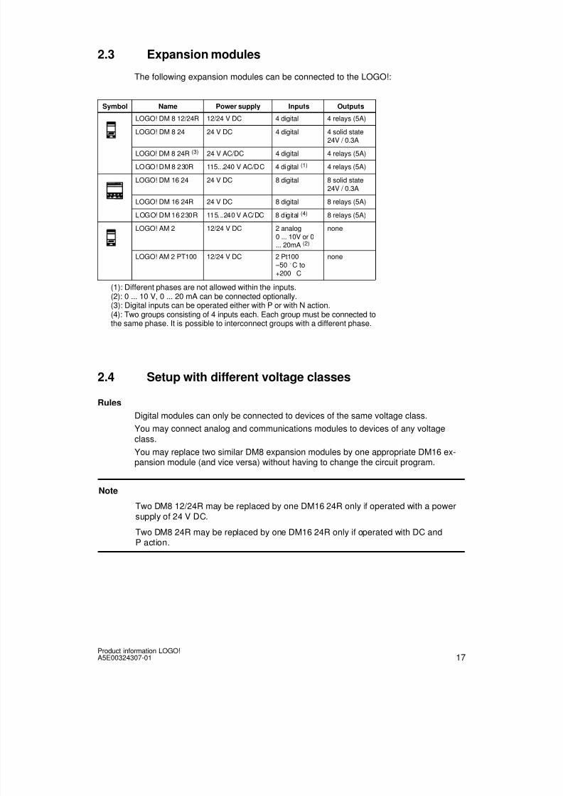
8/10/2019 0900766b805c2bc6
http://slidepdf.com/reader/full/0900766b805c2bc6 331/341
17Product information LOGO!A5E00324307-01
2.3 Expansion modules
The following expansion modules can be connected to the LOGO!:
Symbol Name Power supply Inputs Outputs
LOGO! DM 8 12/24R 12/24 V DC 4 digital 4 relays (5A)
LOGO! DM 8 24 24 V DC 4 digital 4 solid state24V / 0.3A
LOGO! DM 8 24R (3) 24 V AC/DC 4 digital 4 relays (5A)
LOGO! DM 8 230R 115...240 V AC/DC 4 digital (1) 4 relays (5A)
LOGO! DM 16 24 24 V DC 8 digital 8 solid state24V / 0.3A
LOGO! DM 16 24R 24 V DC 8 digital 8 relays (5A)
LOGO! DM 16 230R 115...240 V AC/DC 8 digital (4) 8 relays (5A)
LOGO! AM 2 12/24 V DC 2 analog0 ... 10V or 0... 20mA (2)
none
LOGO! AM 2 PT100 12/24 V DC 2 Pt100 –50 C to+200 C
none
(1): Different phases are not allowed within the inputs.(2): 0 ... 10 V, 0 ... 20 mA can be connected optionally.(3): Digital inputs can be operated either with P or with N action.(4): Two groups consisting of 4 inputs each. Each group must be connected tothe same phase. It is possible to interconnect groups with a different phase.
2.4 Setup with different voltage classes
Rules
Digital modules can only be connected to devices of the same voltage class.
You may connect analog and communications modules to devices of any voltageclass.
You may replace two similar DM8 expansion modules by one appropriate DM16 ex-pansion module (and vice versa) without having to change the circuit program.
Note
Two DM8 12/24R may be replaced by one DM16 24R only if operated with a power
supply of 24 V DC.
Two DM8 24R may be replaced by one DM16 24R only if operated with DC andP action.

8/10/2019 0900766b805c2bc6
http://slidepdf.com/reader/full/0900766b805c2bc6 332/341
18Product information LOGO!
A5E00324307-01
Overview:Connecting an expansion module to LOGO! Basic
LOGO! Expansion modulesBasic
DM8 12/24R,
DM16 24R
DM8 24,
DM16 24
DM8 24R DM8 230R,
DM16 230R
AM2,
AM2 PT100
CM
LOGO! 12/24RC x x x – x xLOGO! 24 x x x – x x
LOGO! 24RC x x x – x x
LOGO! 230RC – – – x x x
LOGO! 12/24RCo x x x – x x
LOGO! 24o x x x – x x
LOGO! 24RCo x x x – x x
LOGO! 230RCo – – – x x x
Overview:Connecting a further expansion module to an expansion module
Expansion Further Expansion modulesmodule
DM8 12/24R,
DM16 24R
DM8 24,
DM16 24
DM 8 24R DM8 230R,
DM16 230R
AM2,
AM2 PT100
CM
DM 8 12/24R,DM 16 24R
x x x – x x
DM 8 24,DM 16 24
x x x – x x
DM 8 24R x x x – x x
DM 8 230R,DM 16 230R
– – – x x x
AM2 / AM2 PT100 x x x – x x
CM x x x – x x

8/10/2019 0900766b805c2bc6
http://slidepdf.com/reader/full/0900766b805c2bc6 333/341
19Product information LOGO!A5E00324307-01
2.5 Dimensions
The LOGO! installation dimensions are compliant with DIN 43880.
LOGO! can be snap-mounted to 35 mm DIN rails to EN 50022 or on the wall.
LOGO! width:
• LOGO! Basic has a width of 72 mm, which corresponds with 4 subunits.
• LOGO! expansion modules have a width of 36 mm or 72 mm (DM16...), which cor-responds with 2 or 4 subunits.
2.6 Connecting LOGO! inputs
Sensor characteristics for LOGO!
LOGO! DM1624 R
LOGO! DM1624
LOGO! DM16230 R (AC)
LOGO! DM16230 R (DC)
Signal status 0 < 5 V DC < 5 V DC < 40 V AC < 30 V DC
Input current < 1 mA < 1 mA < 0.05 mA < 0.05 mA
Signal status 1 > 12 V DC > 12 V DC > 79 V AC > 79 V DC
Input current > 2 mA > 2 mA > 0.08 mA > 0.08 mA
Note
The digital inputs of LOGO! 230 RC/RCo and of expansion module DM16 230R aredivided into two groups, each consisting of four inputs. Within the same group, allinputs must be operated on the same phase. Different phases are only possible
between the groups.Example: I1 to I4 on phase L1, I5 to I8 on phase L2.
Inputs within the LOGO! DM8 230R may not be connected to different phases.
Sensor connections
Connecting glow lamps and 2-wire proximity switches (Bero) to LOGO!230 RC/230 RCo or LOGO! DM8 230 R (AC) and LOGO! DM16 230R (AC)
L1N
NL1
C3SB1420-3D
Order number for C:
Siemens
Switchgear & Systems
X-capacitor 2.5 kV, 100 nF

8/10/2019 0900766b805c2bc6
http://slidepdf.com/reader/full/0900766b805c2bc6 334/341
20Product information LOGO!
A5E00324307-01
2.7 Technical data
General technical data
Criterion Tested in accordancewith
Values
LOGO!Basic
Dimensions (WxHxD) 72 x 90 x 55 mm
Weight Approx. 190 g
Installation on a 35 mm profile rail4 module widthsor wall mounting
LOGO! expansion modulesDM8..., AM...
Dimensions (WxHxD) 36 x 90 x 53 mm
Weight Approx. 90 g
Installation on a 35 mm profile rail2 module widths
or wall mountingLOGO! expansion modulesDM16...
Dimensions (WxHxD) 72 x 90 x 53 mm
Weight Approx. 190 g
Installation on a 35 mm profile rail4 module widthsor wall mounting
Climatic conditions
Ambient temperature
Horizontal installation
Low temperature to IEC60068-2-1 0 ... 55 C
Vertical installationHigh temperature to
IEC 60068-2-2
...0 ... 55 C
Storage/shipping -40 C ... +70 C
Relative humidity IEC 60068-2-30 From 10 to 95 %no condensation
Air pressure 795 ... 1080 hPa
Pollutants IEC 60068-2-42
IEC 60068-2-43
SO2 10 cm3 /m3, 4 days
H2S 1 cm3 /m3, 4 days
Ambient mechanical conditions
Protection mode IP20
Vibrations: IEC 60068-2-6 5 ... 9 Hz (constant amplitude3.5 mm)
9 ... 150 Hz (constant accel-
eration 1 g)Shock IEC 60068-2-27 18 shocks
(half-sine wave 15g/11 ms)
Drop IEC 60068-2-31 Drop height 50 mm
Free fall (packaged) IEC 60068-2-32 1 m
Electromagnetic compatibility (EMC)
Noise emission EN 55011/AEN 55022/B
EN 50081-1(domestic area)
Limit class B group 1

8/10/2019 0900766b805c2bc6
http://slidepdf.com/reader/full/0900766b805c2bc6 335/341
21Product information LOGO!A5E00324307-01
Criterion ValuesTested in accordancewith
Electrostatic discharge IEC 61000-4-2
Severity 3
8 kV air discharge
6 kV contact discharge
Electromagnetic fields IEC 61000-4-3 Field strength 10 V/m
HF currents on cables and cableshielding
IEC 61000-4-6 10 V
Burst pulses IEC 61000-4-4Severity 3
2 kV (supply and signal lines)
High-energy surge pulse(applies only toLOGO! 230 ...)
IEC 61000-4-5Severity 3
1 kV (power lines)symmetrical
2 kV (power lines)asymmetrical
Safety to IEC / VDE
Clearance and creepage distancerating
IEC 60664,IEC 61131-2, EN 50178cULus to UL 508, CSAC22.2 No. 142With LOGO!230 R/RC,
also VDE 0631
Fulfilled
Insulation strength IEC 61131-2 Fulfilled

8/10/2019 0900766b805c2bc6
http://slidepdf.com/reader/full/0900766b805c2bc6 336/341
22Product information LOGO!
A5E00324307-01
Technical data: LOGO! DM16 230R
LOGO! DM16 230R
Power supply
Input voltage 115 ... 240 V AC/DC
Permissible range 85 ... 265 V AC
100 ... 253 V DCPermissible mains frequency 47 ... 63 Hz
Power consumption
• 115 V AC 10 ... 60 mA
• 240 V AC 10 ... 40 mA
• 115 V DC 5 ... 25 mA
• 240 V DC 5 ... 20 mA
Voltage failure buffering
• • 5 typ. ms
• y .
Power loss at• 115 V AC 1.1 ... 4.5 W
• 240 V AC 2.4 ... 5.5 W
• 115 V DC 0.6 ... 2.9 W
• 240 V DC 1.2 ... 4.8 W
Backup of the real-time clock at 25 C
Accuracy of the real-time clock
Digital inputs
Number 8
Electrical isolation No
Input voltage L1
• Signal 0
• Signal 1
• Signal 0
• Signal 1
< 40 V AC
> 79 V AC
< 30 V DC
> 79 V DC
Input current at
• Signal 0 < 0.05 mA
• Signal 1 > 0.08 mA
Delay time at
•0 to 1 typ. 50 ms
• 1 to 0 typ. 50 ms
Line length (unshielded) 100 m
Digital outputs
Number 8
Output type Relay outputs
Electrical isolation Yes
In groups of 1
Control of a digital input Yes

8/10/2019 0900766b805c2bc6
http://slidepdf.com/reader/full/0900766b805c2bc6 337/341
23Product information LOGO!A5E00324307-01
LOGO! DM16 230R
Continuous current Ith max. 5 A per relay
Incandescent lamp load (25000 switching cycles) at
230/240 V AC
115/120 V AC
1000 W
500 W
Fluorescent tubes with ballast (25000 switchingcycles) 10 x 58 W (at 230/240 V AC)
Fluorescent tubes, conventionally compensated(25000 switching cycles)
1 x 58 W (at 230/240 V AC)
Fluorescent tubes, uncompensated (25000 switch-ing cycles)
10 x 58 W (at 230/240 V AC)
Short circuit-proof cos 1 Power protection B16600A
Short-circuit proof cos0.5 to 0.7
Power protection B16900A
Derating None; across the entire temperaturerange
Parallel output circuits for power increase Not permitted
Protection of output relay(if desired)
max. 16 A,characteristic B16
Switching rate
Mechanical 10 Hz
Ohmic load/lamp load 2 Hz
Inductive load 0.5 Hz

8/10/2019 0900766b805c2bc6
http://slidepdf.com/reader/full/0900766b805c2bc6 338/341
24Product information LOGO!
A5E00324307-01
Technical data: LOGO! DM16 24
LOGO! DM16 24
Power supply
Input voltage 24 V DC
Permissible range 20.4 ... 28.8 V DC
Reverse polarity protection YesPermissible mains frequency
Power consumption from 24 V DC 30 ... 45 mA
0.3 A per output
Voltage failure buffering
Power loss at 24 V 0.8 ... 1.7 W
Backup of the real-time clock at 25 C
Accuracy of the real-time clock
Digital inputs
Number 8Electrical isolation No
Input voltage L+
• Signal 0 < 5 V DC
• Signal 1 > 12 V DC
Input current at
• Signal 0 < 1 mA
• Signal 1 > 2 mA
Delay time at
• 0 to 1 typ. 1.5 ms
• 1 to 0 typ. 1.5 ms
Line length (unshielded) 100 m
Digital outputs
Number 8
Output type Transistor,current-sourcing
Electrical isolation No
In groups of
Control of a digital input Yes
Output voltage Supply voltageOutput current max. 0.3 A
Continuous current Ith
Incandescent lamp load (25000 switching cycles) at
Fluorescent tubes with ballast (25000 switchingcycles)
Fluorescent tubes, conventionally compensated(25000 switching cycles)
Fluorescent tubes, uncompensated (25000switching cycles)

8/10/2019 0900766b805c2bc6
http://slidepdf.com/reader/full/0900766b805c2bc6 339/341
25Product information LOGO!A5E00324307-01
LOGO! DM16 24
Short circuit-proof and overload-proof Yes
Short-circuit current limitation Approx. 1 A
Derating None; across the entire temperaturerange
Short circuit-proof cos 1
Short-circuit proof cos 0.5 to 0.7
Parallel output circuit for power increase Not permitted
Protection of output relay (if desired)
Switching rate
Mechanical
Electrical 10 Hz
Ohmic load/lamp load 10 Hz
Inductive load 0.5 Hz

8/10/2019 0900766b805c2bc6
http://slidepdf.com/reader/full/0900766b805c2bc6 340/341
26Product information LOGO!
A5E00324307-01
Technical data: LOGO! DM16 24R
LOGO! DM16 24R
Power supply
Input voltage 24 V DC
Permissible range 20.4 ... 28.8 V DC
Reverse polarity protection YesPower consumption from 24 V DC
30 ... 90 mA
Voltage failure buffering
• 24 V DC typ. 5 ms
Power loss at 24 V
• 24 V DC 0.7 ... 2.5 W
Backup of the real-time clock at 25 C
Accuracy of the real-time clock
Electrical isolation No
Digital inputs
Number 8
Electrical isolation No
Input voltage
• Signal 0 < 5 V DC
• Signal 1 > 12 V DC
Input current at
• Signal 0 < 1 mA
• Signal 1 > 2 mA
Delay time at
• 0 to 1 typ. 1.5 ms
• 1 to 0 typ. 1.5 ms
Line length (unshielded) 100 m
Digital outputs
Number 8
Output type Relay outputs
Electrical isolation Yes
In groups of 1
Control of a digital input YesOutput voltage
Output current
Continuous current Ith max. 5 A per relay
Incandescent lamp load (25000 switching cycles) at 1000 W
Fluorescent tubes with ballast (25000 switchingcycles)
10 x 58 W
Fluorescent tubes, conventionally compensated(25000 switching cycles)
1 x 58 W

8/10/2019 0900766b805c2bc6
http://slidepdf.com/reader/full/0900766b805c2bc6 341/341
27Product information LOGO!A5E00324307-01
LOGO! DM16 24R
Fluorescent tubes, uncompensated (25000switching cycles)
10 x 58 W
Short circuit-proof and overload-proof
Short-circuit current limitation
Derating None; across the entire temperaturerange
Short circuit-proof cos 1 Power protection B16600A
Short-circuit proof cos 0.5 to 0.7 Power protection B16900A
Parallel output circuit for power increase Not permitted
Protection of output relay (if desired) max. 16 A,characteristic B16
Switching rate
Mechanical 10 Hz
ElectricalOhmic load/lamp load 2 Hz
Inductive load 0.5 Hz
2.8 Order numbers
Table A
Variant Designation Order number
Basic LOGO! 12/24RC *
LOGO! 24 *
LOGO! 24RC (AC)
LOGO! 230RC
6ED1 052-1MD00-0BA4
6ED1 052-1CC00-0BA4
6ED1 052-1HB00-0BA4
6ED1 052-1FB00-0BA4
Basicwithout display(pure)
LOGO! 12/24RCo *
LOGO! 24o *
LOGO! 24RCo (AC)
LOGO! 230RCo
6ED1 052-2MD00-0BA4
6ED1 052-2CC00-0BA4
6ED1 052-2HB00-0BA4
6ED1 052-2FB00-0BA4
Digital modules LOGO! DM 8 12/24RLOGO! DM 8 24
LOGO! DM 8 24R
LOGO! DM 8 230R
LOGO! DM 16 24
LOGO! DM 16 24R
LOGO! DM 16 230R
6ED1 055-1MB00-0BA16ED1 055-1CB00-0BA0
6ED1 055-1HB00-0BA0
6ED1 055-1FB00-0BA1
6ED1055-1CB10-0BA0
6ED1055-1NB10-0BA0
6ED1055-1FB10-0BA0
Analog modules LOGO! AM 2
LOGO! AM 2 PT100
6ED1 055-1MA00-0BA0
6ED1 055-1MD00-0BA0
*: Also with analog inputs