0900 - bryce bregen - tyler boyd - mark niehus wideband cdma. 1g 1981-1998 3g 1998-2017 2g ......
TRANSCRIPT

DAS Boot Camp- Next Generation Wireless Networks -

Bryce Bregen Bryce Bregen has more than 20 years of executive-level sales management and channel development expertise in telecom and wireless. Having overseen more than 2,100 distributed antenna system installations across a wide range of vertical markets, Bregen uses his comprehensive industry knowledge to educate businesses on in-building wireless solutions from A to Z.
Bregen is a BICSI corporate member and presenter on DAS trends, a council member of the DAS Standards Committee of the HETNET Forum, an ACUTA corporate member and presenter, and a New York Wireless Association member.
Tyler BoydAs an RF engineer for Connectivity, Tyler applies his concentrated in-building wireless (DAS) knowledge to ensure best-in-class system design, performance and consistent RF engineering throughout the U.S.
With project experience spanning several industries—including hospitality, higher education, commercial, and sporting and entertainment—Boyd has designed, engineered, commissioned and managed some the nation’s largest venues, while providing extensive customer support throughout the duration of each project.
Boyd is certified in all major DAS technologies.
Mark Niehus, RCDDMark is Director of Strategic Accounts for Connectivity Wireless Solutions. He has more than 25 years of ICT installation, project management, and sales and marketing experience. He has been an RCDD since 1997.
Mark has presented to BICSI Fall Conference (2015, Future of Wireless) and several regional BICSI meetings (2014 and 2015) as well as numerous customer-specific seminars and has authored articles for various industry trade magazines.
Connectivity Wireless Solutions is an industry-leading technology solutions provider.
With more than 300 years of combined RF industry experience, and one of thefirst companies to break into the DAS industry, Connectivity has providedthousands of unique solutions to meet the wireless needs of venues and facilitiesthroughout the U.S. since 2008.Having integrated systems across virtually every market and industry, Connectivitytakes pride in matching each customer with exactly the right technology to ensurethat its wireless and IT network needs are met.


Agenda• Next Gen Wireless Trends• Next Gen Wireless Solutions• Infrastructure Deep Dive• Carriers and Case Studies
NextGen Wireless Trends
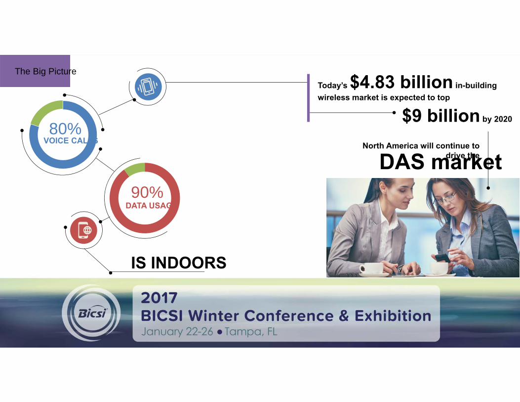
80%
90%
VOICE CALLS
DATA USAGE
IS INDOORS
The Big PictureToday’s $4.83 billion in-building wireless market is expected to top
North America will continue to drive theDAS market
$9 billion by 2020

Future Technology Forecast
VoLTEVoWLAN (Voice over Wireless LAN)
LTE Aggregation
IOT5G
Emphasis on increasedBulking up bandwidth and infrastructure
HERE TODAYHERE TOMORROW
capacity.

Future Technology Forecast
VoLTEVoWLAN (Voice over Wireless LAN)
LTE Aggregation
IOT5G
Emphasis on increasedBulking up bandwidth and infrastructure
HERE TODAYHERE TOMORROW
capacity.

Internet of ThingsA network of internet-connected objects (“things”) able to collect and exchange data
24 billion IoT devices installed by 2020 with
$6 trillion invested in IoT solutions over the next 5 years
83%OF EXPERTS say that by 2025, IoT will have widespread and
beneficial effects on the everyday lives of the public

Internet of Things: Impact
Infrastructure
Monitoring
VRConvenience(traffic, parking)
Public Safety EnhancementsSmart
Home SmartCar
WearableTech
Telemedicine and
mHealth
S OF 5G

5GNot one specific technology, but a standard of service
KEY CONSUMER BENEFITS OF 5G
1 2 3
Connect everythingResponsiveness Speed

5G: What is the migration path to 5G?
2GGSM
Global System for Mobile Comm
iDenIntegrated Digital
Enhanced Network
CDMACode Division
Multiple Access
2.5GGPRS
General Packet Radio Services
EDGEEnhanced Data Rates
for GSM Evolution
3GUMTS
Universal Mobile Telecom System
HSPA+High Speed
Packet Access
EvDOEvolution Data
Optimized
4GeUTRAEvolved UMTS
Terrestrial Radio Access
WiMaxWorldwide
Interoperability for Microwave Access
LTELong Term Evolution
WCDMAWideband CDMA

1G1981-1998
3G1998-2017
2G1991-2010
5G2017+
4G2010-2017+
Years
5G: A New Standard in Quality
14
911
1311
Years to Peak
8
13
7 79
Peak to End of Life

5G: A New Standard in Quality
BRINGS MORE SPEED(10 times faster)
CONNECTS MORE DEVICES(100 times more)
ALLOWS FOR A MORE RESPONSIVE NETWORK(5 times reduced end to end network latency)
3G384 Kbps
[2000]
4G100 Mbps
[2010]
5G>1 Gbps[2020+]

5G: What Are Carries Doing?
RESEARCHING 5G
IMPROVING INFRASTRUCTURE(carrier aggregation, VoLTE, RCS)
EXPANDING INFRASTRUCTURE(DAS, small cell)

Small Cells
1+ million shipments in North America in 2014
$2.7 billion in 2017
48%CAGR
Through
2019
$5.98 billion by 2019
Deployments expected to double in subsequent years

Small Cells: Photos

Small Cells
STRENGTHS
CHALLENGES
Solution flexibility
Cost effective
Neighbor-width population
Single-carrier solution

Virtual Reality WORKPLAYINTERACT
Changes the way we

Virtual Reality: The Impact
SOCIALIZED ONLINE WORK / TEACHING ENVIRONMENTSVIRTUALDATING
CULTURAL IMERSION EXPERIENCES /TRAVEL
TRAINING SIMULATIONS
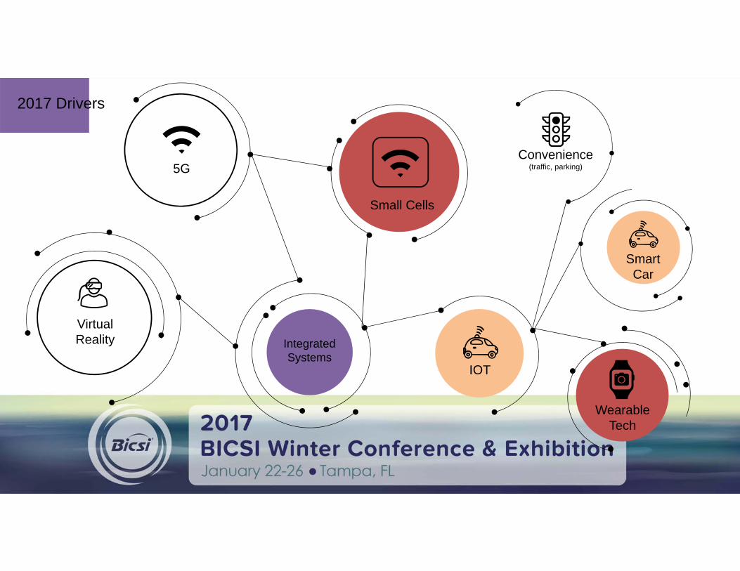
2017 Drivers
5G
VirtualReality Integrated
SystemsIOT
Convenience(traffic, parking)
SmartCar
WearableTech
Small Cells

The Problem
less aboutCOVERAGE
more aboutCAPACITY
One Simple SolutionDAS

NextGen Wireless Solutions

So,why doesn’tmy phone work?
Signal Quality
SignalStength
SignalStength
Signal Quality
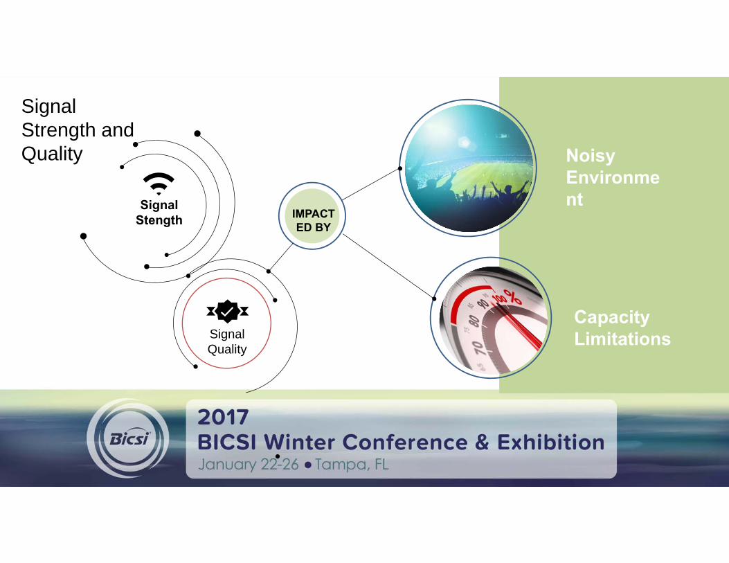
Signal Strength and Quality
IMPACTED BY
Noisy Environment
CapacityLimitations

Signal QualityNoise
s
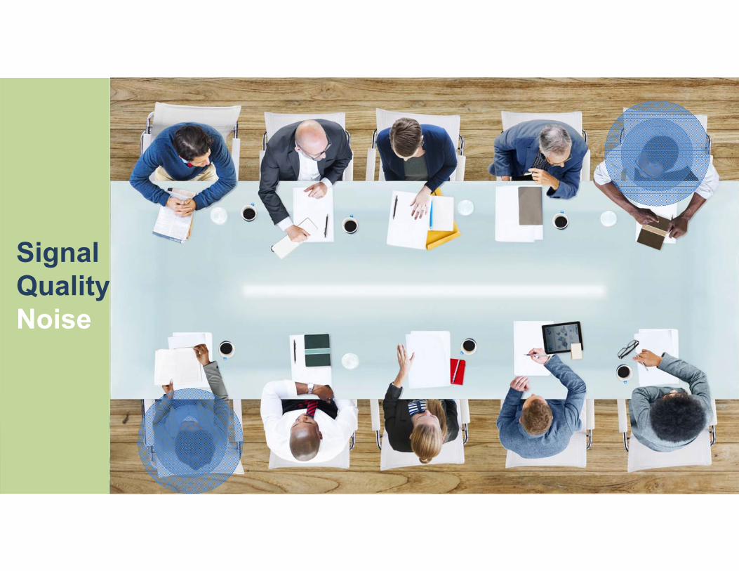
Signal QualityNoise

Signal QualityNoise

Signal QualityNoise

Signal QualityCapacity

Signal QualityCapacity

Signal QualityCapacity

Signal QualityCapacity

Signal QualityCapacity
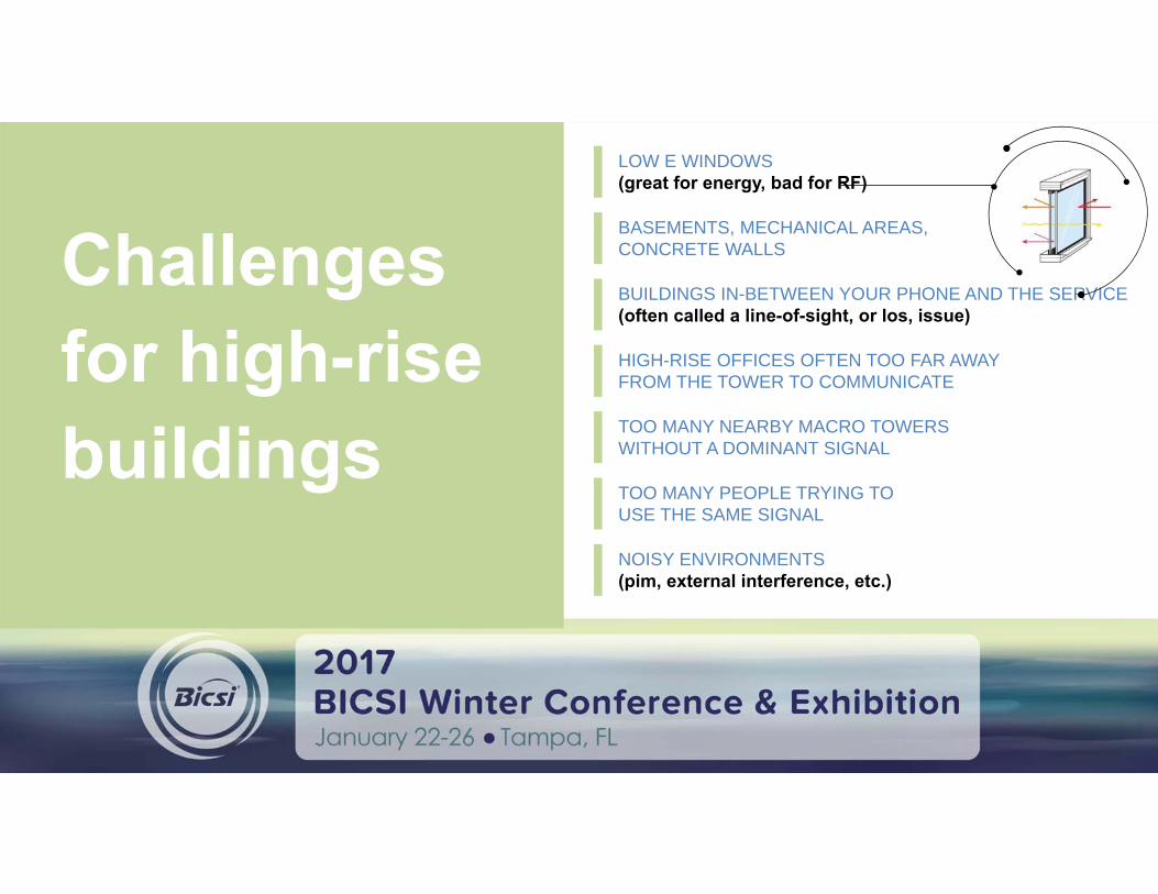
Challenges for high-rise buildings
LOW E WINDOWS(great for energy, bad for RF)
BASEMENTS, MECHANICAL AREAS, CONCRETE WALLS
BUILDINGS IN-BETWEEN YOUR PHONE AND THE SERVICE (often called a line-of-sight, or los, issue)
HIGH-RISE OFFICES OFTEN TOO FAR AWAY FROM THE TOWER TO COMMUNICATE
TOO MANY NEARBY MACRO TOWERS WITHOUT A DOMINANT SIGNAL
TOO MANY PEOPLE TRYING TO USE THE SAME SIGNAL
NOISY ENVIRONMENTS(pim, external interference, etc.)

Network Improvements: What Are Carries Doing About It?
CARRIERS IMPROVE THEIR MACRO INFRASTRUCTURE AND FOOTPRINT
CARRIERS CAN BETTER UTILIZE THE INFRASTRUCTURE THEY ALREADY OWN

A properly designed, installed, commissioned, and maintained DAS solves every Signal Strength and Signal Quality issue.
CLEAN, CLEAR COMMUNICATION TO THE S

Infrastructure Deep Dive

HEAD-END EQUIPMENT ROOM
COAX CABLING
PUBLIC SAFETY DONOR SITE
DONOR ANTENNADAS Architecture Overview
COAX
FIBER CABLING
REMOTE UNIT
IN-BUILDING ANTENNAS
BDA SIGNAL SOURCE
FIBER DISTRIBUTION HEAD-END EQUIPMENT
BTS SIGNAL SOURCE
DAS HEAD-END EQUIPMENT AND FIBER DISTRIBUTION

COAX CABLING
PUBLIC SAFETY DONOR SITE
DONOR ANTENNATraditional DAS Architecture
COAX
FIBER CABLING
REMOTE UNIT
IN-BUILDING ANTENNAS
AN
HEAD-END EQUIPMENT ROOM
BDA SIGNAL SOURCE
FIBER DISTRIBUTION HEAD-END EQUIPMENT
BTS SIGNAL SOURCE
DAS HEAD-END EQUIPMENT AND FIBER DISTRIBUTION

HEAD-END EQUIPMENT ROOM
FIBER CABLING
PUBLIC SAFETY DONOR SITE
DONOR ANTENNAFiber to the Edge Architecture
IN-BUILDING ANTENNASAND REMOTES
COAX
FIBER CABLING
COAX
BTS SIGNAL SOURCE
BDA SIGNAL SOURCE
FIBER DISTRIBUTION HEAD-END EQUIPMENT
DAS HEAD-END EQUIPMENT AND FIBER DISTRIBUTION

Players in the DAS Ecosystem
DASIntegrator
Cable Contractors
DASOEMS
Wireless Carriers
Distribution
Consultants
A&E Firms
End-user Consum
er

DAS Lifecycle
• Requirements Gathering• Needs Assessment• System Design• Proposal
• System Installation• Commissioning and ATP
• Maintenance and Support

Benchmark Data Collection
Collecting and recording carrier data helps with
CARRIER NEGOTIATIONS
PROPER DESIGN

Benchmark Data Collection

Benchmark Data Collection
CW Testing
Collecting and recording the characteristics of the facility helps with
PROPER DESIGN

Data Collection Examplethe facility helps with

Carrier Coordination
Site SurveyOBJECTIVETo ensure that the system can be constructed per the specifications of the design and to help determine additional value engineering specifics.
RF OBSTACLES
INTERIOR WALL MATERIALS
CEILING HEIGHTS AND TYPES
PURPOSE OF BUILDING
VERTICAL CHASES

Design

Wireless Design Thresholds
NEW WORL
D
OLD WORL
D
85 dBm mobile RSSI over 90-95%
of the area for voice
technologies
70 dBm for data centric technologies
(EVDO, LTE, etc.)
6-8 dB stronger than the macro network coverage bleeding into the building
Wireless Design Thresholds

Bidirectional Amplifier (BDA)
Enterprise Femtocell(E-Femto)
Base Transceiver
Station (BTS)
Small Cell
RF Sources –What am I going to connect to the DAS?
DAS

Design: 3D Modeling
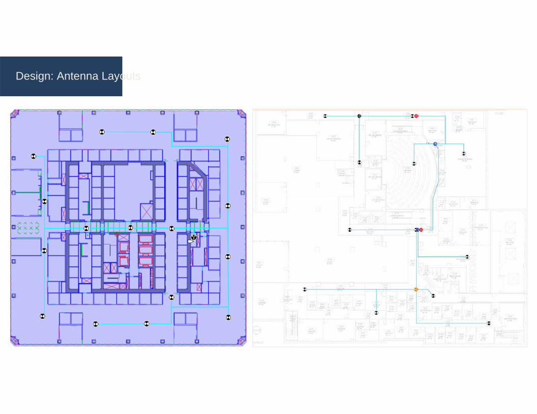
Design: Antenna Layouts

Design: Riser Diagrams
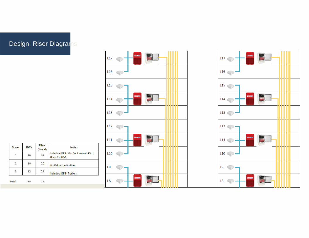
Design: Riser Diagrams
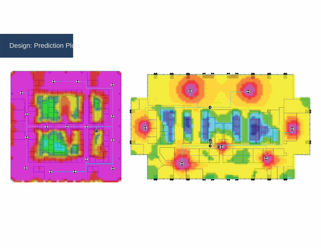
Design: Prediction Plots

Design: Prediction Plots
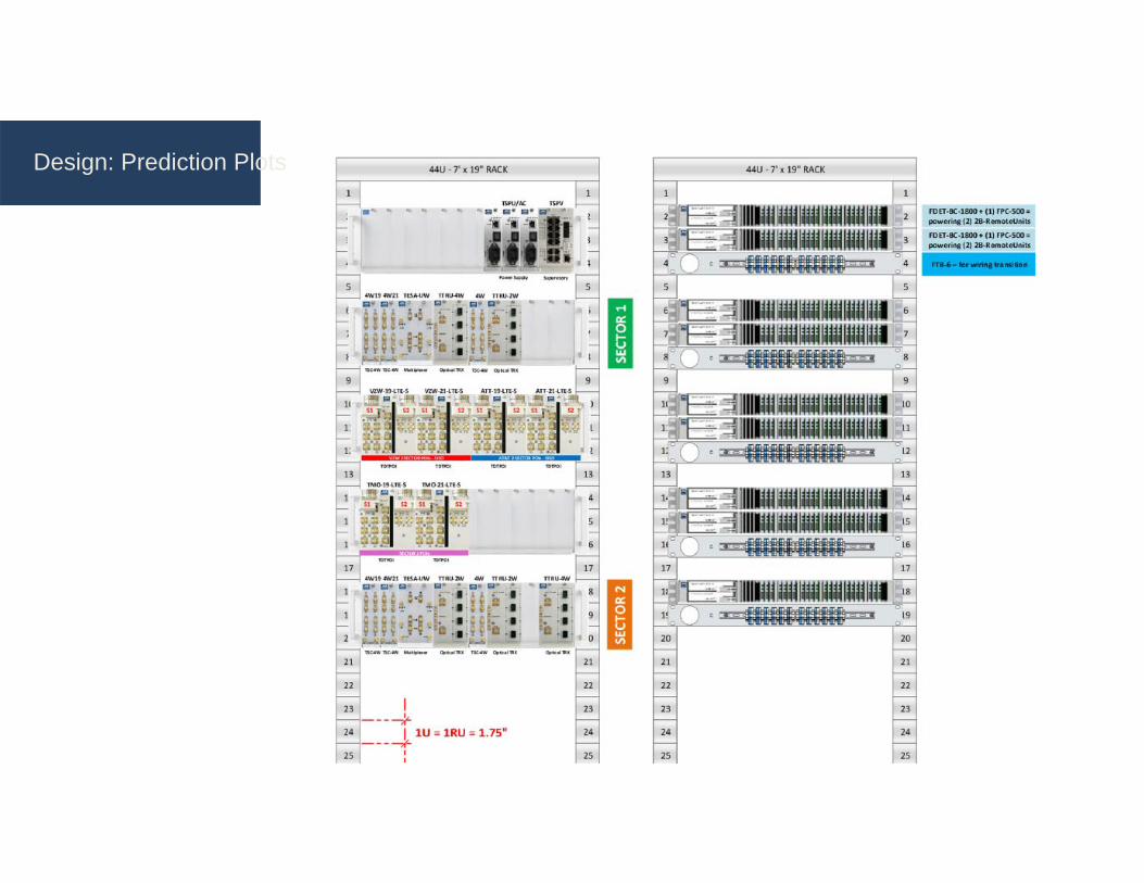
Design: Prediction Plots

Design: Piecing It All Together

DASWiFiWiFiWiFiPONMDF IDF
Fiber Cellular – Wifi – LAN
Design: Converged Networks

NETWORKPACKET VOICE
RF
PON
ONE DAS
VALUENeutral-host DAS = Venue controls,
manages, and operates its own
network
Seamless connectivity on any
network with any device = Enhanced
customer experience
Combined fiber management, powering and
power backup = Reduced CAPEX
and OPEX
BUILDING AUTOMATION
APPLICATIONS
VoIP PHONE
WIFI ACCESS POINT
POINT OF SALE
SECURITY SUREILLANC
E
RF VIDEO AND IP VIDEO
SMARTPHONE & TABLETS
Design: The Value of Convergence
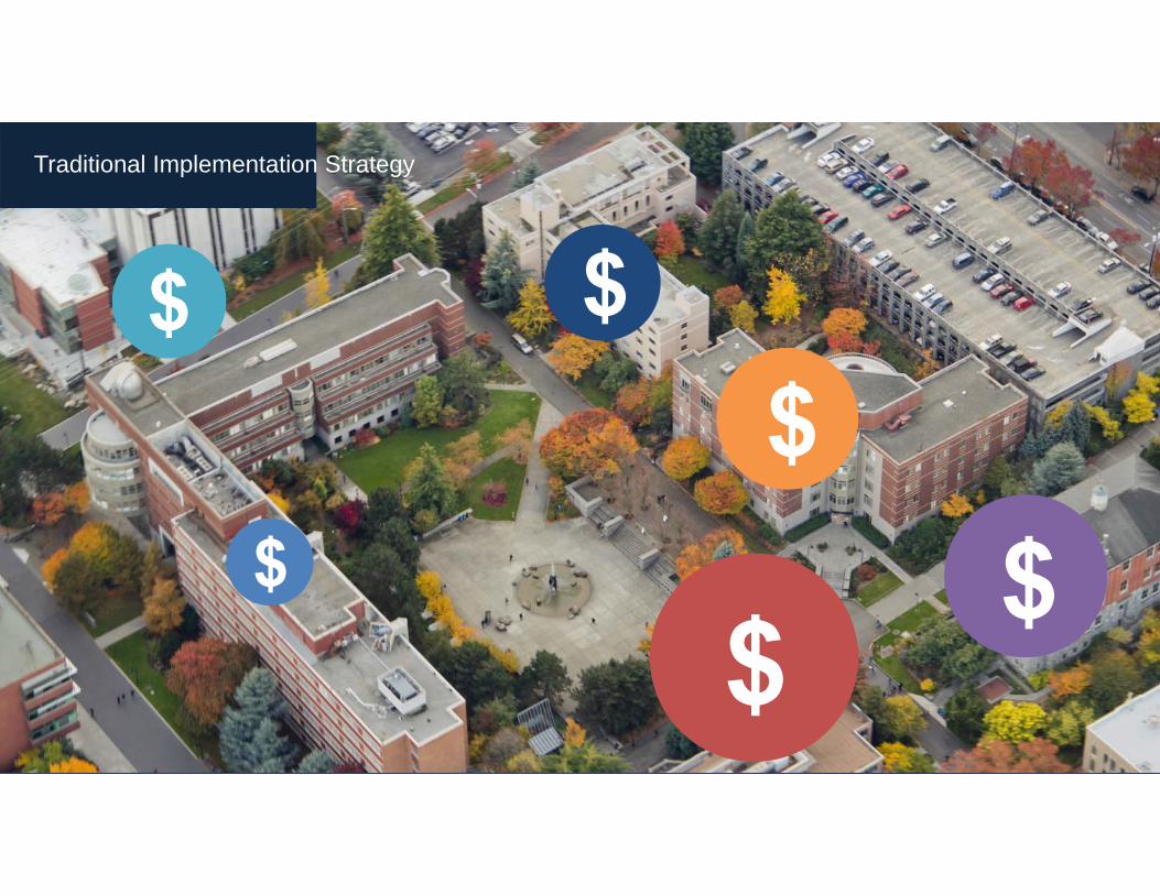
Traditional Implementation Strategy
$
$ $$
$$

$ $
$
$
$
Comprehensive Portfolio Strategy
$

Comprehensive Portfolio Strategy
$ $$
$
$$

IN-HOUSE TEAM OR DIRECT
MANAGEMENT
ON-SITE CONSTRUCTION
MANAGEMENT
PROFESSIONALISM
DETAILED DOCUMENTATION
FOR EACH PROJECT
STRATEGIC INSTALLATION
APPROACH
SWEEP, PIM AND OTDR
STANDARDS
Best Practices
DAS Installation
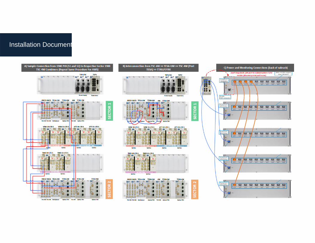
Installation Documentation

Installation Documentation

BASE STATIONSHead-end radio equipment, provided by the wireless carriers, that provides the RF signal source to drive the DAS
FIBER HEAD-END Converts the RF signal to RF-over-fiber (RFoF), then transmits the signal via single-mode fiber-optic cable to the fiber remote unit
MULTI-BAND REMOTE UNITConverts the RFoF transmission back to an RF signal, which is then transmitted down coax cable to the coverage antenna
FIBER OPTIC CABLE Transports the converted RF signals from the head-end equipment to the remote unitsPLENUM CABLETransports the RF signals from the fiber remote unit―to the coverage antennaSPLITTERSplits the RF signals, which is then delivered to multiple inputs/elementsCOVERAGE ANTENNASemits multi-band RF signals to the coverage area
Installation Components

Passive Components

Active Components
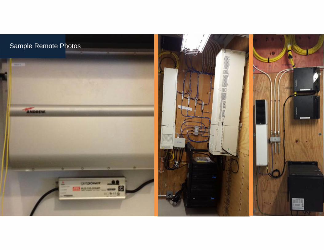
Sample Remote Photos

Sample Remote Photos

Sample Antenna Photos
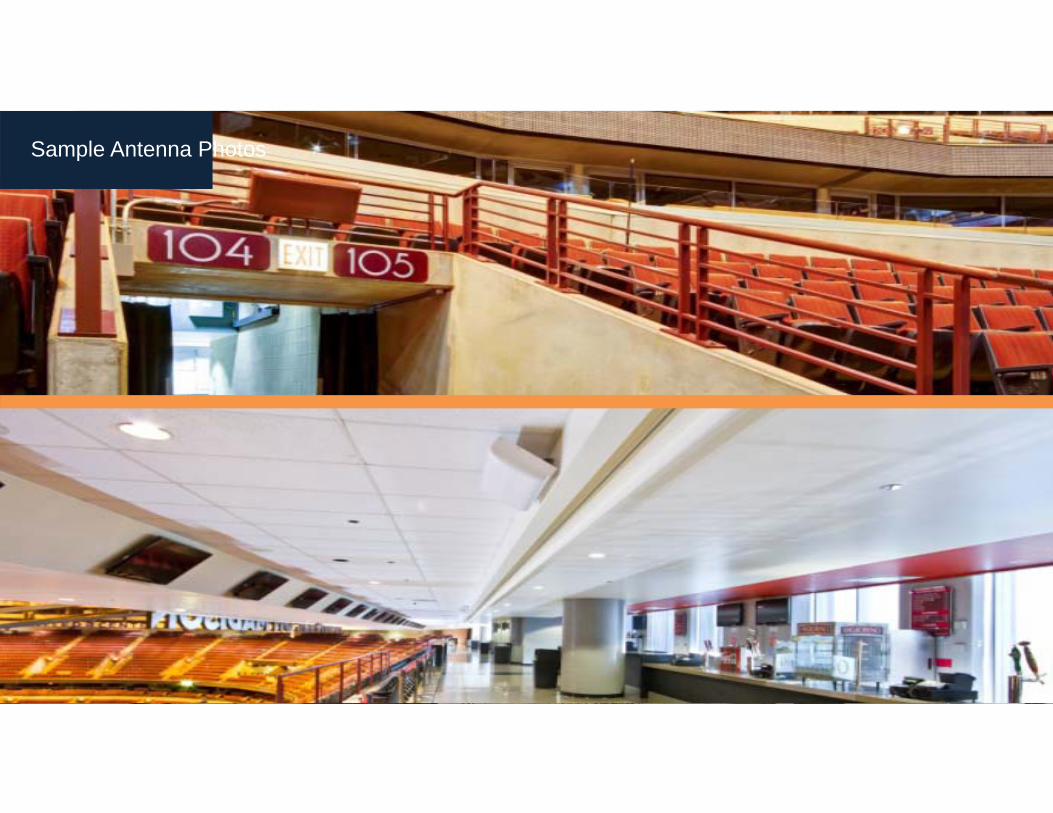
Sample Antenna Photos

Sample Antenna Photos

Before After
Aesthetics

Aesthetics

Commissioning is generally defined as the industry approved process and methodology of systematically verifying that the:DAS • System was installed correctly according to the design
• Active and passive components are functioning according to factory specification
• Link budget and associated DAS power metric performance matches the design specifications
• Intended carrier signals are integrated onto the DAS according to design and are done so within optimum equipment parameters
• Intended carrier signals are optimized to the systems optimum performance metrics, as determined by the design
Commissioning

Tools for Success

SWEEPS –RL/DTF
FIBER
PIM
Data Processing

PIM Passive Intermodulation exists when two or more signals are present in a passive device that exhibits nonlinear response
Data Processing: PIM
What is PIM?

Equipment Green Light
Testing
IntegrationDAS Floor Sensitivity
Optimization
Commissioning Process
Baseline Noise Floor Measurements

LET’S TALK ABOUT THE HEADEND (MDF).
Space PowerEnvironmental Requirements
Floor Loading
Head End Planning

SPACE FOR WIRELESS CARRIER BASE TRANSCEIVER STATIONS (BTS) – SINGLE SECTOR• 200 square feet per wireless carrier
• 800 to 1,000 square feet to accommodate all carriers
• Typically utilize existing MDF, but rooms can be retrofit to accommodate head end equipment
POWER REQUIREMENTS FOR THE HEAD-END ROOM• 100 Amps 208 VAC three phase per carrier
ENVIRONMENTAL REQUIREMENTS FOR THE HEAD-END• 2 tons HVAC per wireless carrier
Floor Loading• 125 PSF for BTS equipment
Head End Room: Requirements

Head End Room: A&E Drawings

Head End Room: Photos

Head End Room: Carrier Equipment

Complex systems require maintenance and preventative checkups to ensure longevity and optimal functionality.
Monitoring and Maintenance
Carriers & Case Studies
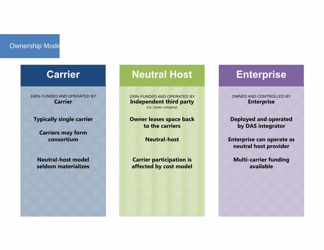
Ownership Models
Carrier Neutral Host Enterprise
100% FUNDED AND OPERATED BYCarrier
Typically single carrier
Carriers may form consortium
Neutral-host model seldom materializes
100% FUNDED AND OPERATED BY Independent third party
(i.e., tower company)
Owner leases space back to the carriers
Neutral-host
Carrier participation is affected by cost model
OWNED AND CONTROLLED BYEnterprise
Deployed and operated by DAS integrator
Enterprise can operate as neutral host provider
Multi-carrier funding available

Ownership Models
Carrier Neutral Host EnterprisePROS
Free is good
No maintenance oroperational issues
Coverage-issue solved for those with that specific carrier
CONSVery challenging for other carriers to
join the system
Pricing barriers
Technical barriers
PROSFree is good
No maintenance oroperational issues
Neutral means that any/ all carriers can join system
Possible revenue share
CONS‘Anchor carrier’ model puts unfair
burden on 1st carrier to join- delays process of implementation
Heavy fee/ finance/ mark-up on top of the system costs can make deal
unattractive to carriers
Customer cannot touch system-unable to control upgrades/ enhancements/ related fiber
infrastructure
PROSNeutral system that any/ all carriers
can join
Customer owns and control technology and infrastructure, in same way they do with structured
cabling, network equipment, security, A-V, etc.
Leverage of system and infrastructure (fiber) for Wi-Fi
When structured correctly- system can be funded by carriers
CONSPotential gaps between cost of system and funding by carriers
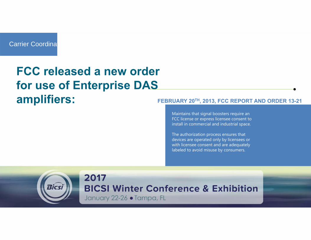
Carrier Coordination
FCC released a new order for use of Enterprise DAS amplifiers: FEBRUARY 20TH, 2013, FCC REPORT AND ORDER 13-21
Maintains that signal boosters require an FCC license or express licensee consent to install in commercial and industrial space.
The authorization process ensures that devices are operated only by licensees or with licensee consent and are adequately labeled to avoid misuse by consumers.

critical
Wireless carrier coordination is to the success of any DAS project
PHASE 1 PHASE 2 PHASE 3 PHASE 4 PHASE 5 PHASE 6
INITIATION• Ecosystem Summary• Carrier Engagement• Carrier Registration
• RF Source Qualifying
FUNDING• Business Case
Development• Carrier Financial
Analysis• Funding Decision
DESIGN• Design Review
• Design Acceptance• RF Source Specification
REGULATORY• Submittals
• Review• Acceptance
AUTHORIZATION• Agreement Development
• Agreement review• Agreement Execution
Integration• RF Source Installation
• RF Source Commissioning • RF Source testing
CarrierConnect™Wireless Carrier Coordination Methodology

CHURCHILL DOWNS
RESULT:
› Supported the record-breaking data demand at a single event of 5 terabytes to sere combined Derby and Oaks attendance of 290,000 people
› Second largest system in the nation by sector count; covers 4.68 million
› Installation and Optimization efforts were met on time for the 2015 race while maintaining excellent signal throughout the venue
› AT&T and Verizon 4G and LTE coverage
CUSTOMER CHALLENGE:
› Historic venue called for sensitive design and installation
› Sheer size and density of the coverage required to meet the needs of the facility
› Tight project timeline to optimize prior to Kentucky Derby weekend
CONNECTIVITY’S SOLUTION:› Installed a 51-sector DAS to provide extensive coverage
throughout the facility, including infield, suites, luxury suites, six main floors and two sublevels
› Designed using Corning equipment, 271 antennas and more than 1 million ft of fiber
Case Study

KINNICK STADIUMUniversity of Iowa
RESULT:
› Installed and concealed 180 antennas, 360 remotes, and 58,000 ft. of fiber/composite cable. Allowing for excellent coverage while adhering to uncompromising aesthetic requirements.
› DAS network provides ubiquitous coverage to fans inside the facility -servicing a total of 700,000 square feet.
CUSTOMER CHALLENGE:
› Historic Kinnick Stadium of the University of Iowa was challenged to provide reliable wireless and data throughput speeds to fans during events.
› Strict aesthetic requirements coupled with the need for ubiquitous, robust coverage to meet the 70,000 maximum capacity requirements for multiple carriers.
CONNECTIVITY’S SOLUTION:
› Designed a 23 zone, neutral-host, ‘fiber to the edge’ Corning ONE DAS for the university.
› DAS designed for dominance for all wireless carriers, supporting the technology and frequency bands owned in the market today with infrastructure to allow for future upgrades.
Case Study

HAWKEYE – CARVER ARENA University of Iowa
RESULT:
› Installed and concealed 84 antennas, 168 remotes, and 29,000 ft. of fiber/composite cable. Allowing for excellent coverage while adhering to uncompromising aesthetic requirements.
› DAS network provides ubiquitous coverage to fans inside the facility - servicing a total of 500,000 square feet.
CUSTOMER CHALLENGE:
› Historic Carver-Hawkeye Arena of the University of Iowa was challenged to provide reliable wireless and data throughput speeds to fans during events.
› Strict aesthetic requirements coupled with the need for ubiquitous, robust coverage to meet the 16,000 maximum capacity requirements for multiple carriers.
CONNECTIVITY’S SOLUTION:
› Designed a 7 zone, neutral-host, ‘fiber to the edge’ Corning ONE DAS for the university.
› DAS designed for dominance for all wireless carriers, supporting the technology and frequency bands owned in the market today with infrastructure to allow for future upgrades.
Case Study

ONE WORLD TRADE CENTER New York
CUSTOMER CHALLENGE:
› Glass and steel architecture of building prevented cellular service from reaching the core and sub-levels of building; minimal coverage in tenant floors up to 45th floor
› Tenant-Building management contracts required wireless coverage on occupied floors
› Located in one of the most densely populated business districts in the world, causing capacity issues in and around the building
› One World Trade Observatory handling an average of 12,000 visitors per day (more than half a million visitors in the first three opening months)
› One-third of building tenant-occupied upon installation start.
› Security of building required increased administrative work to arrange access for work, deliveries and testing
Case Study

ONE WORLD TRADE CENTER New York
CONNECTIVITY’S SOLUTION:› More than 200,000 feet of ½’ coax and 7,000+ feet of fiber
› 1,250 antennas
› 24x7 construction, installation and commissioning hours to complete two floors per weekend. (Total of 24 floors)
› One project manager on site with three construction managers throughout the installation, adding one performance engineer for commissioning and testing
› Verizon 4G and LTE
› Completed in fewer than seven months. UL/DL testing completed in one week; six weeks ahead of schedule
Case Study

ONE WORLD TRADE CENTER New York
Case Study
Questions?- Thank you -
Bryce Bregen
SVP Sales & Marketing602-321-6555
Tyler Boyd
Solutions Engineer678-925-2626
Mark Niehus
Director of Strategic Accounts206-380-0082