09 spec for 11kv 24v ptr lv vcbs with diff - … spec for 11kv 24v...inter-connection cable from...
TRANSCRIPT

1
Revised on 29.03.2014
TECHNICAL SPECIFICATION FOR 11KV 24V DC PTR LV VCBs WITH CONTROL & RELAY
PANELS AND CTs OF RATIO 600-300/1-1-0.577A
(WITH DIFFERENTIAL PROTECTION)

2
I SCOPE:
This specification covers the manufacture, assembly, supply and delivery of Destination stores of 11 KV (Vacuum) Out Door porcelain clad pad type circuit breakers including current transformers, meters, relays and control panels for outdoor installations. The power system is with neutral solidly earthed. The equipment shall be guaranteed for 5 years.
II. APPLICABLE STANDARDS:
Unless otherwise modified in this specification, the Circuit Breakers, Current Transformers etc. shall comply with the following Standards with latest amendments.
IS 13118/1991 – High Voltage A.C. Circuit Breakers. IEC 62271-100/2008– Circuit Breakers (latest version). IS 2705 (Part I to IV/1992) – Current Transformers. IS 335 -Oil IS 2633 - Galvanization IS 10601 Primary terminals IS 2099/1986 – Bushings for Alternating Voltages. IS 13010/2003 IS 13779/1999 – Energy Meters IS 3231/1986 & 87 – Relays. IS 1248/2003 – Ammeters & Voltmeters. IS 13947/Pt 1/93 – Degree of protection provided by Enclosures.
III. CLIMATIC CONDITIONS:
The climatic conditions under which the equipment shall operate satisfactorily are as indicated at clause No.22 of General and Financial terms and conditions for supply of materials.
IV . PRINCIPAL PARAMETERS:
1. CIRCUIT BREAKERS :
1.1. Nominal System Voltage : 11KV 1.2 Type : Vacuum porcelain clad 1.3 Service : out door 1.4 No. of Poles/Phases : THREE 1.5 High system voltage : 12KV 1.6 Rated Frequency : 50 Hz 1.7 System of earthing : Neutral solidly grounded 1.8 Insulation level : 1.8.1. Impulse withstand Voltage : 75 KVP 1.8.2 One minute power frequency: 28 KV (rms) withstand voltage. 1.8.3 Power frequency withstand : 2 KV (rms) Voltage on Auxillary circuit

3
Note: Please note that the above insulation levels supply at the reference conditions of temperate, pressure and humidity specified below:
Temperature : 20 degree C. Pressure : 1013 millibars Humidity : 11 g/m 3
1.9 Rated Thermal Current : 1250 A 1.10. Rated short circuit breaking current: 1.10.1. Symmetrical : 25 KA/3Sec 1.10.2. Asymmetrical : As per IS – 13118/1991 or IEC-62271-100/2008 1.11. Rating making capacity : 2.50 times Rated Short circuit breaking Current (Symmetrical) 1.12 Rated short time withstand Current for 3 Sec. : 25 KA 1.13 Total break time : 60 m sec (max) 1.14 Bushing Insulator Creepage distance : Not less than 300 mm 1.15. Mounting : Steel Structure 1.16. Rated Operating Sequence: O-0.3S – CO-3min - CO 1.17. Operating Mechanism : Motor operated/Manual spring Charged. The standard
DC Voltage for the operating devices shall be 24V DC. Operating Voltage for motor spring charging mechanism shall be 250V with +/- 20%, DC/AC single phase . Normally the breaker shall be operated by Power and there shall be provision for manual operation.
1.18. Terminal Connector : 1.18.1. Material : Aluminium 1.18.2. Suitable for : Panther ACSR 1.19. Limits of temperature : The limits of temperature shall be in accordance with IS-
13118/IEC-62271-100/2008 1.20. Requirement of Simultaneity of Poles : The maximum difference between instants of contact
touching during closing and the maximum difference between the instant of contacts separation during opening between 3 poles shall not exceed one half cycle of the rated frequency. The Breaker shall be open and close simultaneously on all three phases for fault on any phase and or all the phases.
1.21 Protection : The Breaker shall be provided with (I) 3 Nos. over Current (O/L) and one Earth fault (1
E/L) IDMT. relays as per GTP .The following Auxiliary Relays are to be provided for Power Transformer protection.
(a) BUCHOLTZ ALARAM. (b) OLTC BUCHOLTZ ALARAM
i. ex e
4
(c) WINDING TEMP/OIL TEMP. HIGH ALARAM.
The following shall be with 2NO+2NC contacts & Hand Reset type.
(d) BUCHOLTZ RELAY TRIP. (e) OLTC BUCHOLTZ RELAY (f) WT/OT Trip (g) Master Trip relay
II) Anti pumping relay. III) Numerical Differential relay for PTR protection Note: The Numerical relays shall preferably be self powered with high set features with IDMT 1.3 Sec. Over current Relay settings ranging from 5% to 200% in steps of 1% and earth fault relay settings ranging from 5% to 80% in steps of 1%.
Settings for high set instantaneous elements for relays of 11KV Feeder VCBs shall be as follows. High Set Instantaneous feature :
Over current 50% to 2000% in steps of 5% for 24V DC
Earth Fault 50% to 2000% in steps of 5% for 24V DC
Over current ,earth fault time setting start from 0.01 to 1Sec in steps of 0.01Sec The relays shall have facility of minimum 5 Nos. fault tripping data such as 1.fault magnitude 2.Date and time of occurrence 3.Flag indication
“The over current relays shall be Numerical draw out type and all other relays are of non-draw out type”.
The over current relays should be of make as per bill of materials with IDMT characteristics and also with high set instantaneous elements for high fault currents and shall comply with IS- 3231.
1.22 Auxiliary Power Supply : 1.22.1 A.C. Supply : 250 V + or – 20% (Phase to neutral), , 50 HZ + or – 5%, Effectively earthed system. 1.22.2 D.C. Supply : 24V + or – 20%, 2 wire ungrounded system. 1.22.3 Supply point: 1.22.3.1 Auxillary power supplies listed above will be made
available to each circuit breaker as below : A.C. Supply : Single Feeder D.C. Supply : Single feeder
1.22.3.2 M.C.B. shall be provided at the circuit breaker for each Incoming A.C. Supply. For D.C. supply double pole M.C.B. shall be provided. (with different colours for easy identification). The rating of MCBs shall be 10A.

5
2 CURRENT TRANSFORMERS : LV Control
2.1 Rated voltage : 11 KV 2.2. Type : Single phase outdoor live tank oil cooled Vacuum impregnated type 2.3. Earthing : Solidly earthed 2.4 Insulation level 2.4.1. Nominal system voltage : 11 KV 2.4.2. Highest system voltage : 12 KV 2.4.3. Impulse withstand voltage : 75 KV peak 2.4.4. One minute power frequency
withstand voltage a. Primary (HV) : 28 KV b. Secondary (LV) : 3 KV
2.5. Frequency : 50 Hz 2.6. Transformation ratio : 600-300/1-1-0.577A 2.7 Rated secondary current (Amp) : i) Core I (Protection) : 1 ii) Core II (Metering) : 1 iii)Differential(Class OS) : 0.577 2.8 Rated output (VA) : i) Protection : 15 ii) Metering : 5 iii)Differential(Class PS) : -- 2.9. Class of accuracy : 2.9.1.i) Protection (Core I) : 5P10 2.9.1.ii)Metering (Core II) : 0.2S iii)Diff.protection (Core III) : PS
a) Maximum Knee point Voltage Requirement : 40 I (Rct +10) I = Rated current of CT.
b) Maximum Exitation current : 30mA at 0.25 Vk – 2.10 Short time thermal current
and its duration : 25KA/3Sec The short time thermal current should Suit the breaker rupturing capacity and duration to suit the maximum tripping Time.
2.11. Accuracy Limit factor : 10 for protective core 2.12 Class of Insulation : Immersed in new insulating oil. 2.12.1 Limit of Temp. Rise (Max.) : 55 °C. 2.13 Rated Continuous Thermal Current : 630 A NOTE: The CTs shall be live tank out door type and shall be offered with first filling of
oil. The oil shall confirm to the latest IS:335.
6
V. TECHNICAL REQUIREMENTS: I. CIRCUIT BREAKERS
1.1 DESIGN CRITERIA
The equipment will be used in High Voltage system having characteristics as listed in the specification.
The equipment will be installed outdoor in hot, humid and tropical atmosphere.
All equipment, accessories and wiring shall have tropical protection, involving special treatment of metal and insulation against fungus, insects and corrosion.
The maximum temperature in any part of the equipment at specified rating shall not exceed the permissible limits as stipulated in the relevant standards.
The equipment shall be capable of withstanding the dynamic and thermal stresses of listed short circuit current without any damage or deterioration.
The safety clearances of all live parts of the equipment shall be as per relevant standards.
1.2 TYPE AND DUTY:
The circuit breaker shall be outdoor, 3-pole, vacuum type M2 class (minimum 10,000 operations) in case of 11KV having internal isolation without any sequential interlock.
In the event of order, the tenderer have to offer at least one breaker tested in respect
of Temperature rise test and Mechanical endurance test of 10,000 Mechanical operations
(M2 Class) in presence of purchaser representative as an acceptance test.
The duty of the circuit breaker shall involve satisfactory interruption of short circuit currents as listed in the clause-IV (Principal Parameters).
The breaker shall be capable of interruption of reactive current (lagging/leading) without under/over voltage.
1.3 CONSTRUCTION FEATURES :
1.3.1 GENERAL ARRANGEMENTS :
The circuit breaker shall have fixed type construction consisting three single identical poles, complete with a gang operated mechanism for specified duty. The interrupters shall be enclosed in a sealed porcelain housing conforming to protection to IS 13947 Pt1 equivalent IP- 65 protection (IS:2147). All three poles of circuit breaker shall be linked together electrically / mechanically to ensure simultaneous closing/tripping of all poles.
The trip free operating mechanism, 3 phase inter connection links shall be completely accommodated in the base. There shall be sufficient clearance between live parts of the circuit breakers and the ground. The circuit breaker shall be complete with operating mechanism, other accessories/materials to ensure complete assembly and proper functioning. The current transformers shall be externally mounted on the supporting structure integrated with circuit Breaker structure. Terminal connectors suitable for panther ACSR conductor for 11KV should be supplied for Circuit Breakers and CTs. The circuit breaker shall be provided with proper standard earthing and with terminal earth bar for earthing connection. Suitable

7
inter-connection cable from breaker terminal, CTs terminal to control relay panel is 2.5 Sq.mm. PVC copper control cable (un-armored) are to be provided.
Neither the circuit breaker nor any part of the switchgear or its supporting structures shall be permanently strained due to vibration etc. when making or breaking the rated short circuit currents.
The details of any device incorporated in the current breakers to limit or control the rate of restriking voltage across the circuit breaking contacts shall be stated.
The vacuum interrupter assembly used in the circuit breakers shall be interchangeable with indigenously available vacuum interrupters (make and type shall be mentioned.).
All metal enclosures shall be fabricated from minimum 2.5mm CRCA steel sheet free from all surface defects. The panel shall have sufficient structural re-enforcement to ensure a plain surface to limit vibration and to provide rigidity during dispatch and installation.
1.3.2 MAIN CONTACTS AND ARC QUENCHING CHAMBER :
The main contacts shall have adequate area and contact pressure for carrying rated continuous and short time current without excessive heating liable to cause pitting and welding.
The tips of the arcing and main contacts shall be special copper-Chromium alloy.
The contacts that are adjustable to allow for wear, shall be easily replaceable and shall have minimum movable part and adjustments. The arc-quenching device shall be of robust construction and shall not require any critical adjustment. The devices shall be easily accessible and removable for access to the breaker contacts.
Flexible laminations shall be of electrolytic copper. The ends of the laminations shall be solidified with hot pressed /electro fusion/Electro solidification method to ensure good electrical contacts and achieve minimum contact resistance.
1.3.3 INTERLOCK :
All electrical and mechanical interlocks which are necessary for safe and satisfactory operation of the circuit breaker shall be furnished.
1.3.4 AUXILIARY CONTACTS :
Each breaker shall be provided with 6 normally open and 6 normally closed electrically separate spare Auxiliary contacts in addition to those required for its own operation and indication exclusively for purchaser’s use.
The auxiliary contacts shall be rated for 10A for AC and 10A for DC.
Note : 1. 1no Spare tripping coil and 1no closing coil shall be clamped in the Breaker.
2. Spring charging multiplier with 2 NO+2NC shall be available and shall be wired to the spare terminal blocks.

8
3. Auxiliary switch contact multiplier shall also be incorporated in the control panel and shall be wired to the spare terminal blocks.
4. INSULATORS :
Bushing insulators for circuit Breakers shall comply with IS2099-1986 specification for High Voltage porcelain bushings.
Insulators shall be wet process porcelain, brown glazed and free from all blemishes. Ferrous metal parts and hardware shall be hot-dip galvanized.
Insulators shall have adequate mechanical strength and rigidity to withstand the duty involved.
When operated at maximum system voltage, there shall be no electrical discharge. Shielding rings, if necessary, shall be provided. Insulation shall be coordinated with basic impulse level of the system. The creepage distance shall correspond to heavily polluted atmosphere.
1.4. OPERATING MECHANISM:
The operating mechanism shall be motor operated and manual operated spring closing mechanism with trip free features complete with shut trip coils. All three poles of the breaker shall operate simultaneously. It shall operate in principle in such a way that the closing springs after each closing operation, are automatically charged by the motor and locked in the charged position by a latch. Means shall be provided to charge the springs manually also. Provision shall be made for the slow closing of the VCB irrespective of spring charge position.
The contact loading spring shall be designed in such a way that the closing stroke be completed and the opening stroke is commenced only from fully closed position. All the breakers shall be suitable for manual operation as well as slow closing VCB irrespective of spring charge position.
Operation counter and mechanically operated indicator to show whether the circuit breaker is open or closed shall be provided on the circuit breaker operating mechanism.
All manually operating gear shall be so designed that the circuit breaker can be operated by one movement. The mechanism shall be such that the tripping spring can be charged while the circuit breaker is closed and the closing mechanism when charged shall not be operated by vibration caused by the circuit breaker opening under fault conditions.
The mechanism shall be designed for electrical control from remote. Local manual close/trip (lever/button) shall be provided in the mechanism box only.
No mechanical /electrical inter lock shall be inbuilt the manual spring charging of breaker.
Mechanical components other than spring charging mechanism link linkages shaft etc. shall have minimum plating thickness of 10-15 microns. The surface finishing ensures zinc plating trivalent passivation (ROHS compliance) and should withstand for salt spray test in artificial atmosphere upto 192 hours without white rust.

9
All fasteners exposed to Air should be of hot dip galvanized of MS 8.8 Grade for M10 and above and below M10 grade shall be of stainless steel.
The maximum power required for closing coil and shunt trip coil should not be more than 200 watts.
1.5 CONTROL CUBICLE (MECHANISM BOX)
A common control cubicle shall be furnished to house electricals, controls, monitoring devices and all other accessories except those which must be located on individual poles.
The cubicle shall have protection as per IS:13947 Pt1 equivalent IP-55 protection (IS:2147) of gasketed whether proof construction, fabricated from sheet steel minimum 2.5mm thick.
The cubicle shall have front access door with lock and keys, and removable gland plate at the bottom for cable entry.
Additional locking arrangement ( pad locking facility) is to be provided
1.6 WIRING & TERMINAL BLOCKS :
1.6.1 WIRING
Wiring shall be complete in all respects to ensure proper functioning of the control, protection, monitoring and interlocking schemes.
Wiring shall be done with flexible 1100 V grade, PVC insulated switch board wires with 2.5 sq.mm. stranded copper conductor.
CT wirng.. TB must be connected / disconnected type of ledger type 12 way and control wiring terminal ledger must be 16A open type
All CT wiring must be done with 2.5mm/ 4 mm dia ring type lugs only
Each wire shall be identified at both ends with permanent markers bearing wire numbers as per wiring diagram. The wiring schematic may conform to relevant standards.
Wire termination shall be done with crimping type connectors with insulating sleeves.
All spare contacts of relays, push buttons, auxiliary switchers etc. shall be wired upto terminal blocks in the control cubicle.
1.6.2. TERMINAL BLOCKS : Terminal blocks shall be 1100 V grade, box clamp type (Stud Type). Not more than two wires shall be connected to any terminal. Spare terminals equal in number to 20% active terminals shall be furnished. Terminal blocks shall be located to allow easy access. Wiring shall be so arranged that individual wires of an external cable can be connected to constructive terminals. 1.7 NAME/RATING PLATE:

10
BREAKERS : Each circuit-breaker shall be provided with a name plate or plates legibly and indelibly marked with the following information:
a) Name of manufacturer. b) Type of designation and serial number. c) Rated Voltage and current. d) Rated frequency. e) Rated symmetrical breaking capacity. f) Rated making capacity and g) Rated short-time current and its duration. h) P.O.No. with Date i) Period of guarantee
Note : 1. The word “Rated” need not appear on the name plate, recognized abbreviations may be used to express the above quantities.
2. When the circuit breaker is fitted with closing and/or tripping devices necessitating any auxilary supply the nature of the auxiliary supply shall be stated either on the circuit breaker name-plate or in any other acceptable position.
3. The purchase order No. and date and year of supply and the words AP-PDCL must be etched on the name plate.
2.CONTROL & RELAY PANELS :
2.1 CONSTRUCTION :
The Control panels to house meters, relays and other items shall be weather proof and vermin proof and of rust-free pressed steel cubicle type with hinged door and locking device. Ventilation louvers shall be provided with GI mesh. The frame shall be made of angle iron or structural steel of sufficient weight and strength to ensure permanent rigidly and alignment. The control panel shall be provided with inter connections, small wiring leads, terminal bolts, fuses, earth bar, multi core cable glands, earth connections etc, The panel should be provided with locking handle with built-in door lock and lock shall be provided with duplicate keys.
The outdoor panels shall be preferable of the following dimensions :-
Height 1750 mm(Excluding the height of the stand)
Width 600 mm
Depth 600 mm
The exterior of the panels shall be painted with dark admiral grey colour and interior should be painted with half white colour. The panel shall be provided with fuse units/MCBs for AC Circuit (both phase and neutral) for all phases of potential Circuit (Potential coil connections to energy meters etc.) DC Control Circuit etc. The internal wiring of the panels shall be with 2.5 sq.mm 650 V grade standard copper PVC Insulated wiring of reputed make.
The Guage of the sheet steel for the front of the panels (where the meters etc. are fixed) and supporting members of the panels shall be of 3 mm thick and for the other members of the panel sheet steel thickness shall be 2 mm.

11
The suitable interconnection cable from breaker terminal, CTs terminal to control relay panel is 2.5 Sq.mm. PVC copper control cable (un-armored) shall be provided. “Weather proof vermin proof control and relay panel shall be either structure mounted/floor mounted”
2.2 PAINTING:
Before painting all non-galvanised parts shall be completely cleaned and made free of rust, scale and grease and all external rough surface cavities on casting shall be filled by metal deposition.
The interior parts and internal structural steel work shall be cleaned of all scale and rust by sand blasting or other approved method.
All external surface shall receive a minimum of 3 coats of paint(All metal enclosures
shall be treated in 7 tank Pre-treatment process & should be painted with UV Resistant Pure
Polyester Powder coating. The powder coated sheet steel fabrication shall fulfill 700Hrs of Salt
spray test. The thickness of Painting/Powder coating shall be of 70-90 microns to withstand
tropical heat and extremes of weather). The paint shall be guaranteed for 5 years from the date of receipt of material.
3.CURRENT TRANSFORMERS:
3.1 CONSTRUCTION
The core shall be high grade non-ageing electrical silicon-laminated steel of low hysterisis loss and high permeability to ensure high accuracy, at both normal and over current/voltage.
The secondary terminals shall be brought into a compartment on one side of current transformer for easy access. The Secondary terminal shall be provided with short circuiting arrangements of current Transformer The secondary taps shall be adequately reinforced to withstand normal handling, without damage.
The current transformers shall be suitable for mounting on steel structures or concrete pedestals. The necessary flanges, bolts, etc, for the base of the Current Transformer shall be supplied and these shall be galvanized. The current transformer tank and other metal parts shall be galvanized.
All windings of Current Transformers shall be made of high grade electrolytic copper wire double paper covering insulation and the manufacturing of the units shall be done in completely closed and air-conditioned room. Fibre glass insulation sleeves are to be provided for primary winding. Details of winding and core shall be furnished.
The Current Transformers shall be complete in all respects with filling of oil conforming to IS:335 and with oil level indicator with minimum/maximum oil levels. The top cover and terminal box cover should be such that rain water does not enter even through the gaskets.
The to cover of the CT should be designed to avoid the stagnation of water. The creepage distance should be 300mm(min).
The minimum clearance required between poles in air required should be 300mm.

12
Note : Facility for selecting the CT ratio in the control panel by closing the appropriate links in the Control and Relay Panel shall be provided. In no case changing of CT ratio with primary links shall be provided.
3.2. PRIMARY & SECONDARY TERMINALS: Primary terminals of Current Transformers to which the line connections are to be made shall have dimensions as per IS: 10601:1983 and material shall be of tinned cooper. The secondary terminals shall be brought out into suitable compartment, which shall have a removable cover. The terminal box with the cover closed and tightened and the cable/conduit in position when supplied shall have a degree of protection conforming to IP 54 of IS: 2147.The secondary terminals will be M6 Tinned Brass studs. 3.3. TERMINAL AND EARTH CONNECTORS: Terminal connectors suitable for Panther ACSR Conductor shall be supplied. Suitable earth connectors for earthing connections shall also be supplied.
Thickness of the clamp must be minimum of 12mm and the stud clamp will be bimetallic.
3.4. EARTHING: The assembly comprising of the chasis, frame work and the fixed parts of the metal casing of the CT, shall be provided with two separate earthing terminals. The earthing terminals shall be adequate size protected against corrosion and metallically clean and identified by means of the sign marked in a legible and indelible manner on or adjacent to the terminals. 3.5. SEALING ARRANGEMENT: Provision for sealing secondary terminal compartment, primary ratio change strips (if any) and tank effectively shall be made such that no fraud etc. such as tampering of the ratio or circuit (current) is possible. The holes provided for the above sealing provision shall be of adequate size and pass the sealing wire of about 14 SWG.
3.6.Each instrument Transformer shall be provided with prismatic type oil sight window at suitable location so that the oil level is clearly visible with naked eye to an observer standing at ground level. 3.7.For compensation of variation in volume of the oil due to temperature variation nitrogen cushion or stainless steel bellows shall be sued. Rubber diaphragms shall not be permitted for this purpose. 3.8. The units shall be vacuum filled with oil, after processing and thereafter hermetically sealed to eliminate air and moisture from entering the tank. 3.9 NAME/RATING PLATE :
Each Current Transformer shall have the following particulars indelibly marked on it or on a label permanently secure to it or its casing.
a) Manufacturer’s Name : b) Manufacturer’s Sl.No. and /or type of designation: c) Rated transformation ratio : d) Rated Frequency e) Highest system voltage

13
f) Insulation level and g) Rated short time thermal current with the associated rate time and rated
dynamic current. The Purchase Order No. and date and year of supply and the words “AP-PDCL” must be etched on the name plate.
VI. SCHEDULE OF EQUIPMENT
1. CIRCUIT BREAKERS:
Vacuum Circuit Breaker complete with suitable painted steel support structure (with anchor bolts & nuts) for mounting 1 No. circuit breaker – 3 poles. Mechanism box, control and relay panel and Current Transformers.
Note : 1. Earth strips as per IS shall be provided for proper earthing of equipments.
2. Earth bar of copper (suitable for termination of 2 nos. 40 x 6 mm flats) shall be provided on circuit breaker support structure.
3. Connecting Cable from Breaker to Control panel and Breaker to CTs are to be provided.
3 (i) Connecting Cable from Breaker to CTs 6 Core cable of 5 mtrs length from each CT i.e., total 3 x 5 = 15 mtrs / Breaker and from Breaker to Control panel 10 core cable of 15 mtrs length.
3 (ii) Size of interconnection cable from breaker terminal, CTs terminal to control relay panel is 2.5 Sq.mm. PVC copper control cable (un-armored).
2. MECHANISM BOX CONTAINING :
(a) Operating mechanism
(b) Mechanical indicator for “ON” and “OFF” coupled to the Circuit breaker operating mechanism.
(c) Mechanical close and trip (with protective flap) lever/push button.
(d) Terminal blocks for control wiring and a spare terminal block (with 20% of the active terminals).
(e) Operation Counter.
(f) Operating handle for manual charging of springs and for slow closing.
(g) 2 Nos. cable glands over and above those provided for control cables with suitable dummies.
(h) Not less than 6 numbers normally open and 6 normally closed spare auxiliary contacts over and above those required for normal operation.
(i) 250 V single phase AC Motor/Manual operated spring charging mechanism complete with electrical spring release coil, 2 Nos. shunt trip coil and 1 No. closing coil.
(j) Local – Remote selector switch.
(k) Earth bar (suitable for termination of 2 Nos. 50 x 6 mm class)
(l) 6 Nos. Terminal connectors suitable for panther conductor for incoming and outgoing connector for outdoor VCB.
(m) Set of 2 pole MCBs for AC and DC supply with different colours.

14
(n) 1 No. of anti-pumping relay.
If offered breaker is with anti pumping mechanism plug in relay is also acceptable.
(o) TNC Switch heavy duty piston grip type
3. CONTROL AND RELAY PANEL :
Weather proof vermin proof control and relay panel mounted on the breaker structure having equipped as follows :
3 ½ Digit LED Display CT operated digital A.C. Ammeter with Class of Accuracy 0.5 to suit the indicated in Section-IV, Schedule of materials of size (96x96) mm.
a) One ammeter selector switch with “R”, “Y”, “B”, “Neutral” and “OFF” position.
b) One Heavy duty Piston grip type Control Switch for VCB trip/Neutral/Close positions with spring return to neutral position.
c) One Red and one Green indicating lamps for indicating close and open positions respectively.
d) One Yellow lamp for healthy trip indication with push button control.
e) One white lamp for spring charged indication.
f) One amber Lamp for auto-trip indication.
Note: All indication lamps shall be of LED type of voltage 24V DC.
g) One CMRI Compatible 3 phase 4 wire static energy meter class 0.2S accuracy suitable scaled to work on 110 V AC 50 Hz 1 Amp to suit the CT ranges indicated in Section-IV “Schedule of materials” for 11KV LV Control VCBs.
h) Numeric Relays shall be with the following features
a) IDMT relay with 3 poles arranged for O/L and one pole for E/L
b) IDMT relay with 3 poles arranged for O/L and one pole for E/L and with high set instantaneous elements for high fault currents for 11KV LV control VCBs.
c) Master trip relay of 24V DC or equivalent fact acting shall be provided (Hand Reset type).
d) Numerical Differential relay for PTR protection
i) Two Nos. cable glands over and above those provided for control CT, PT, Control Circuit cables and auxiliary supplies (AC&DC) with suitable dummies.
j) 3 ½ Digit LED Display digital A.C. Voltmeter with 7 positions switches with RY-YB-BR-RN-YN-BN-OFF selector switch with size 96x96 Sq.mm
15
k) One set alarm bell and push button for acceptance of alarm. Audio alarms shall be static hooters of reputed make. Voltage rating shall be 24V DC
l) Necessary LT Fuses/MCBs for Control Circuit. Set of fine wiring with ferrules with standard code number of respective terminals and with suitable terminal connectors.
m) 250 V three pin socket with plug & switch.
n) 3Phase 4 Wire Test terminal block with CT and PT terminals with links for testing ammeter and energy meter.
o) Stud terminal blocks (Bolt and nut type) for CT and PT control cables suitably wired with 6 Nos. spare terminals.
p) One suitable copper earth strip of 12 x 3 mm size with adequate number of holes with suitable nuts and bolts.
q) 1 No. push button for Trip Circuit healthy check-up.
r) 1 No. plug point with knob (10A, 250 VAC)
s) 1 No. Illuminator lamp with switch (40W, 250 VAC)
t) 1 No. panel space heater with heater switch thermostat.
u) 1 No. DC supply supervision relay
v) 1 No. 24V DC LED for DC Healthy
w) 1 No. trip circuit supervision relay (Pre and Post close)
x) BUCHOLTZ ALARAM. y) OLTC BUCHOLTZ ALARAM z) WINDING TEMP/OIL TEMP. HIGH ALARAM.
aa) OLTC BUCHOLTZ RELAY
ee) BUCHOLTZ RELAY TRIP with 2NO+2NC contacts & Hand Reset type
NOTE: 1. All the instruments and relays to be provided on control panel shall be flush mounted unless otherwise specified. The relays are to be worked on 1/5 amp dual rated secondary current of CTs and with DC Voltage of 24 V.
2. All the indicating meters (Ammeter, Voltmeter) shall be of 96 x 96 size or standard size.
4. CURRENT TRANSFORMERS.
Three numbers outdoor CTs as specified (Ratios).
a) Terminals connectors suitable for panther ACSR conductor for 11KV shall be supplied for Circuit Breaker (6 Nos.) and CT terminals (6 Nos.)
b) Suitable inter connection between circuit breaker terminals and CT terminals are to be provided.

16
C) Cables from circuit breaker and CTs to control panel shall be provided. As specified in Schedule of equipment.
Note : Other standard accessories which are not specifically mentioned but supplied with breakers of similar type and rating for efficient and trouble free operation shall be provided.
VII. TESTS :
The Circuit breakers and current transformers shall be subjected to the following routine and type tests in accordance with the details specified in the relevant Indian Standards as amended from time to time or any other equivalent international standards.
1. CIRCUIT BREAKER : IS 13118/IEC-62271-100/2008 (Latest version).
Copy of type test reports shall be enclosed to the tender. The date of type tests shall not be later than 5 years as on date of bid opening.
1.1
ROUTINE TESTS
a) Measurement of resistance of the main circuits.
a) Operation tests.
b) One minute power frequency voltage dry withstand test on the circuit breakers.
c) One minute power frequency voltage dry withstand test on auxilliary circuits.
ACCEPTANCE TEST.
d) (i) Visual Check,(ii)Verification of Bill of materials,(iii)Verification of dimensions as per approved drawings.
e) Measurement of resistance of the main circuits.
f) Operation tests (Both Mechanical & Electrical with variable auxiliary voltage 70-110%)
g) VCB Operating timings i.e. Opening and closing timings etc..
h) One minute power frequency voltage(70KV for 1Minute) dry withstand test on the circuit breakers. between phase to earth and across between phase terminals.
i) Auxiliary circuit checking
(i) Voltage test on control and auxiliary circuit 2KV for 1minute between all LT terminals to earth.
(ii) Insulation resistance test.(>1 M Ohm(min)) before and after HV test. Between phase to phase, between open contacts, control wiring.
(iii) Checking of Breaker control switch, Local/Remote Switch, Ammeter & Voltmeter selector switch,Auxilary switch,Anti pumping contactor, ON-OFF Spring charge, Indication lamps, push buttons, Space heater, Thermostat working & Buzzer,
(iv) Operation of meters by applying current and voltage.
(v) Operation of relays by applying current and voltage.
(vi) Interrupter make rating details.

17
1.2 TYPE TESTS :Shall be done as per IS /IEC
Temperature rise test for the main circuits.
a) Measurement of resistance of the main circuit. b) Operation tests. c) Mechanical endurance tests. (M2 class suitable for 10000 operations) d) Impulse voltage tests. e) One minute power frequency voltage dry withstand tests. f) One minute power frequency voltage wet withstand tests. g) Tests for short circuit conditions. h) Tests for short time current.
j) Seismic test.
k) Capacitor switching duty test.
2. CURRENT TRANSFORMERS: 2.1. The following Type tests as per IS 2705 (Latest version) shall be conducted and Type Test Certificates for the Tests carried out on prototype of same specification shall enclosed with the tender. The date of type tests shall not be later than 5 years as on date of bid opening.
a) Short time current Test. b) Temperature rise test. c) Lightning Impulse Test. d) High Voltage Power frequency wet withstand voltage test. j) Determination of errors or other characteristics according to the requirements
of the appropriate designation or accuracy class. 2.2 ACCEPTANCE & ROUTINE TESTS: The following tests shall be conducted as per IS: 2705: 1992.
a) Verification of terminal marking and polarity. b) Power frequency dry withstand Test on primary & secondary windings. c) Over Voltage Interturn test. d) Determination of errors or other characteristics according to the requirements of
the appropriate designation or accuracy class.
Note: Satisfactory Valid type test certificates from Central Govt. /NABL/International labs is to be furnished for the tests mentioned above as per the specification along with tender bid. Type tests applicable as per IS:13118 or IEC – 62271-100. The bid without required type test certificates, the offer shall be treated as non-responsive. Provisional/in house type testing reports are not acceptable. VIII. SPECIAL GUARANTEE FOR CIRCUIT BREAKERS :
i) The Circuit Breakers (total equipment including control and relay panel and CTs) shall be guaranteed for satisfactory operation for a period of 5 years (five years) from the date of receipt at stores.

18
IX. DRAWING:
Drawings and technical literature of Breakers, Current Transformers and panels shall be enclosed to the Officer, Tenders not accompanied by the above are liable to be rejected. These drawings and literature are to be supplied in duplicate copies along with each unit in the event of order and are to be housed in a proper weather proof enclosure on the rear of the control panel door. One set of reproducible drawings shall be supplied. Schematic wiring diagrams of the control circuits of the circuit breaker and control & relay panel shall be displayed (embossed on a plate/Laminated) on the doors of the circuit breaker, control cubicle and control & relay panel respectively.
X. OVERALL DIMENSIONS AND FOUNDATION DETAILS:
The manufacturer shall give the necessary information as regards the overall dimensions of the circuit breaker and foundation details.
XI. PACKING :
All the equipments shall be packed in suitable crates with suitable steel bands so as to withstand rough handling and storage at destination.
XII. SPARE PARTS:
A list of recommended spares including vacuum interrupters may be indicated for operation of each type breaker along with their prices.
The prices of the following spares shall be quoted.
1. Spring charging motor
2. 11kV Interrupter 1250Amp,25KA/3Sec
3. TNC switch
4. Breaker Auxiliary Switch.
5. Tripping Coil & Closing coil.
Spring charge motors, tripping & closing coils shall be supplied 5% of the tender quantity as spares.
XIII. Support structure shall be galvanized as per relevant standards.
XIV . DC Fail shall be sensed by a relay or equivalent and indication of DC Fail shall be
given with an indication lamp.

19
I. GUARANTEED TECHNICAL PARTICULARS FOR CIRCUIT
BREAKERS
(A)
1.
RATED VALUES AND CHARACTERISTICS
As per A PDCL As per Tenderer
a) No. of Poles Three b) Manufacturer’s type & designation
Outdoor Porcelain Clad Vacuum circuit Breaker
c) Rated Voltage 11 KV/12 KV d) Rated Insulation-Level 12KV/28KV/75KV i) Impulse withstand voltage 75KV Peak ii) One minute Power frequency withstand voltage. 28 KV Rms
iii) One minute Power frequency withstand voltage on Auxiliary wiring.
2 KV Rms
e) Rated Frequency 50 HZ f) Rated Thermal Current 1250 A g) Rated Cable charging current 25A h) Rated (Single) Capacitor breaking current 400 A i) Rated Small Inductive breaking current _
j) Rated Symmetrical Short Circuit breaking Current and breaking capacity in MVA.
(25 KA & 350 MVA)
k) Rated Transient Recovery Voltage. 20.6 KV Rms
As per IS : 13118/1991/IEC-62271-100
l) Rated short Circuit making current 62.5KA Peak m) Rated Operating Sequence O-0.3Sec-Co -3Min-CO n) Rated duration of short circuit 3Sec
o) Opening time and Break time (milli Sec.) 60ms max p) Closing Time (Milli Sec.) <100ms max
2. Whether type test certificate enclosed with tender _ 3. Weight of complete Circuit Breaker _ 4. i) Pressure maintained in vacuum chamber. 10-6 torr
ii) Gap between the contacts in Vacuum. 6-8 mm iii) Area of contacts. Adequate iv) The voltage to which the circuit breaker shall be
capable of withstanding indefinitely across open contacts.
12KV
5. Minimum Clearance i) Between Poles 300mm ii) Between Live parts to earth 350mm
6 Details of vacuum interrupter make and ratings
20
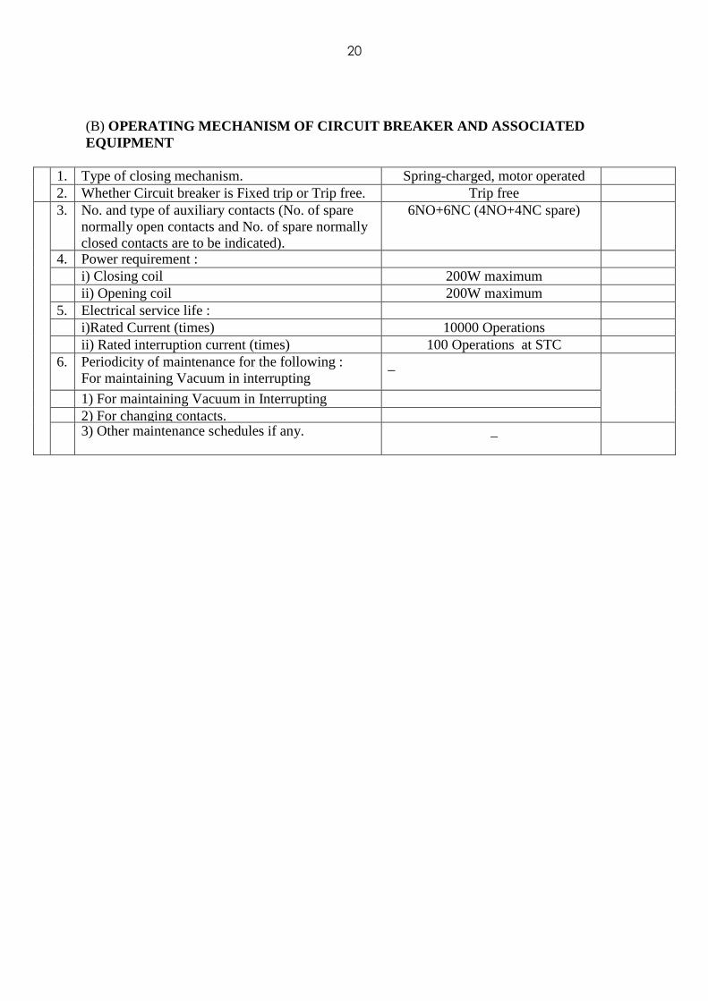
(B) OPERATING MECHANISM OF CIRCUIT BREAKER AND ASSOCIA TED EQUIPMENT
1. Type of closing mechanism. Spring-charged, motor operated 2. Whether Circuit breaker is Fixed trip or Trip free. Trip free
3. No. and type of auxiliary contacts (No. of spare normally open contacts and No. of spare normally closed contacts are to be indicated).
6NO+6NC (4NO+4NC spare)
4. Power requirement : i) Closing coil 200W maximum ii) Opening coil 200W maximum 5. Electrical service life : i)Rated Current (times) 10000 Operations ii) Rated interruption current (times) 100 Operations at STC 6. Periodicity of maintenance for the following :
For maintaining Vacuum in interrupting _
1) For maintaining Vacuum in Interrupting
chamber.
2) For changing contacts. 3) Other maintenance schedules if any. _
21
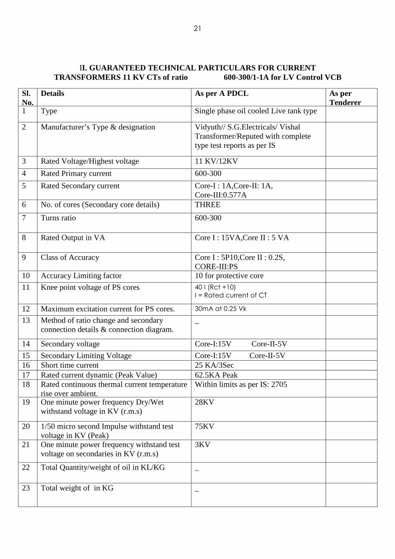
II. GUARANTEED TECHNICAL PARTICULARS FOR CURRENT TRANSFORMERS 11 KV CTs of ratio 600-300/1-1A for LV Control VCB
Sl. No.
Details As per A PDCL As per Tenderer
1 Type Single phase oil cooled Live tank type
2 Manufacturer’s Type & designation Vidyuth// S.G.Electricals/ Vishal Transformer/Reputed with complete type test reports as per IS _
3 Rated Voltage/Highest voltage 11 KV/12KV
4 Rated Primary current 600-300
5 Rated Secondary current Core-I : 1A,Core-II: 1A, Core-III:0.577A
6 No. of cores (Secondary core details) THREE
7 Turns ratio 600-300
8 Rated Output in VA Core I : 15VA,Core II : 5 VA
9 Class of Accuracy Core I : 5P10,Core II : 0.2S, CORE-III:PS
10 Accuracy Limiting factor 10 for protective core
11 Knee point voltage of PS cores 40 I (Rct +10)
I = Rated current of CT
12 Maximum excitation current for PS cores. 30mA at 0.25 Vk
13 Method of ratio change and secondary connection details & connection diagram.
_
14 Secondary voltage Core-I:15V Core-II-5V
15 Secondary Limiting Voltage Core-I:15V Core-II-5V 16 Short time current 25 KA/3Sec 17 Rated current dynamic (Peak Value) 62.5KA Peak 18 Rated continuous thermal current temperature
rise over ambient. Within limits as per IS: 2705
19 One minute power frequency Dry/Wet withstand voltage in KV (r.m.s)
28KV
20 1/50 micro second Impulse withstand test voltage in KV (Peak)
75KV
21 One minute power frequency withstand test voltage on secondaries in KV (r.m.s)
3KV
22 Total Quantity/weight of oil in KL/KG _
23 Total weight of in KG _

22
24 Magnetization curve of CT core _
25 Mounting details _
26 Overall dimensions _
27 Total creepage distance of the bushing 300 mm (min)
28 Phase to phase clearance in air 280mm(min)
29 Live part to the ground clearance 360 mm (min)
30 Whether the CT is hermetically sealed Yes
31 Whether over voltage protection for open circuit of secondary moulded if provided details to be furnished
No
23
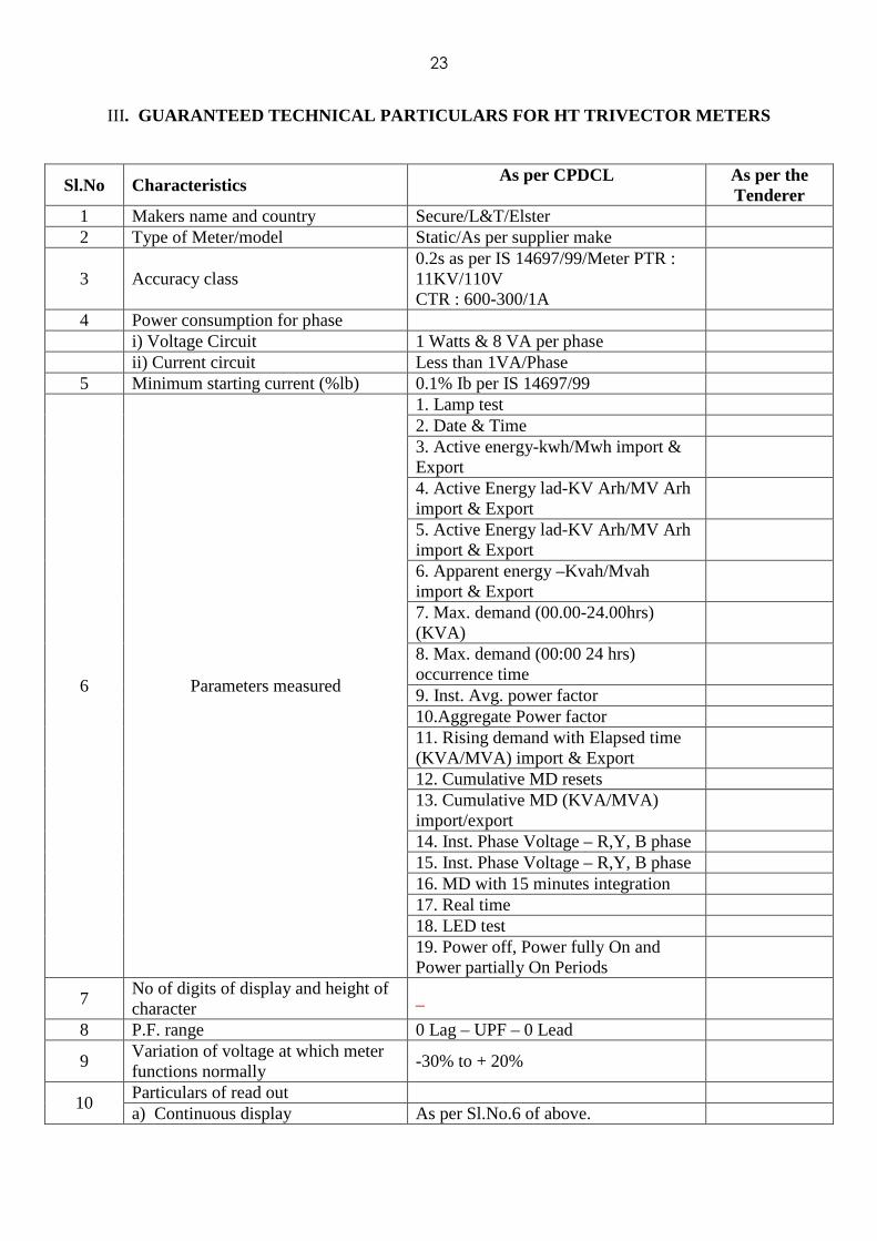
III . GUARANTEED TECHNICAL PARTICULARS FOR HT TRIVECTOR M ETERS
Sl.No Characteristics As per CPDCL As per the
Tenderer 1 Makers name and country Secure/L&T/Elster 2 Type of Meter/model Static/As per supplier make
3 Accuracy class 0.2s as per IS 14697/99/Meter PTR : 11KV/110V CTR : 600-300/1A
4 Power consumption for phase i) Voltage Circuit 1 Watts & 8 VA per phase ii) Current circuit Less than 1VA/Phase 5 Minimum starting current (%lb) 0.1% Ib per IS 14697/99
6 Parameters measured
1. Lamp test 2. Date & Time 3. Active energy-kwh/Mwh import & Export
4. Active Energy lad-KV Arh/MV Arh import & Export
5. Active Energy lad-KV Arh/MV Arh import & Export
6. Apparent energy –Kvah/Mvah import & Export
7. Max. demand (00.00-24.00hrs) (KVA)
8. Max. demand (00:00 24 hrs) occurrence time
9. Inst. Avg. power factor 10.Aggregate Power factor 11. Rising demand with Elapsed time (KVA/MVA) import & Export
12. Cumulative MD resets 13. Cumulative MD (KVA/MVA) import/export
14. Inst. Phase Voltage – R,Y, B phase 15. Inst. Phase Voltage – R,Y, B phase 16. MD with 15 minutes integration 17. Real time 18. LED test 19. Power off, Power fully On and Power partially On Periods
7 No of digits of display and height of character
_
8 P.F. range 0 Lag – UPF – 0 Lead
9 Variation of voltage at which meter functions normally
-30% to + 20%
10 Particulars of read out a) Continuous display As per Sl.No.6 of above.

24
b) manually on display
1. Supply frequency 2. Present PT & CT status 3. Last occurrence tamper ID 4. Time and date of last occurrence 5. Time & date of last tamper restoration
6. Cumulative tamper occurrence counts
c) auto display parameters i) Scrolling period 10 Sec ii) Display off period between two cycles
2 Sec
d) With CMRI/RMR As per technical specification
11
Details of Meter base and cover
a) Type of material 1. base : Poly Carbonate 2. Top : Polycarbonate Transparent
b) Dimensions and weight As per the make of the meter
12 Non volatile memory retention time in absence of power
10Years
13 Memory capacity (kB) Suitable for 36 Days storage)
14 Communication ports and protocol DLMS protocol with RS 232 port in addition to optical port
IV. The guaranteed technical particulars of Numerical Differential relay: Application: Two winding Power transformers Features: Protection: Biased differential (87 HS) Instantaneous Differential High Set (87 HS) Numerical, true RMS measurement Integral current amplitude multiplier and vector group compensation 3 slope adjustable bias setting Immune to magnetic inrush Monitoring: Self monitoring facility User Interface: Seven segment LED display LED indications Other features: Both 1A and 5A CT inputs in one relay

25
Draw out modular case Non volatile memory for trip indication CT Input rating Frequency: 50 Hz Auxiliary Supply: Setting: Current differential: Initial differential setting: 10% to 50% of In in steps of 50% Bias slope: 10% to 70% of In in steps of 5% Bias slope limit: 200% to 2000% of initial in steps of 100% Current amplitude correction for HV Winding: 0.50 to 2.50 in steps of 0.01 Current amplitude correction for LV Winding: 0.50 to 2.50 in steps of 0.01 Vector group compensation for HV winding & LV winding Differential High set: Off, 400% to 2500% of initial in steps of 100% Typical Operating time: Current Differential: 30 m sec at 2x setting Highest over current: 25m sec at 2x setting
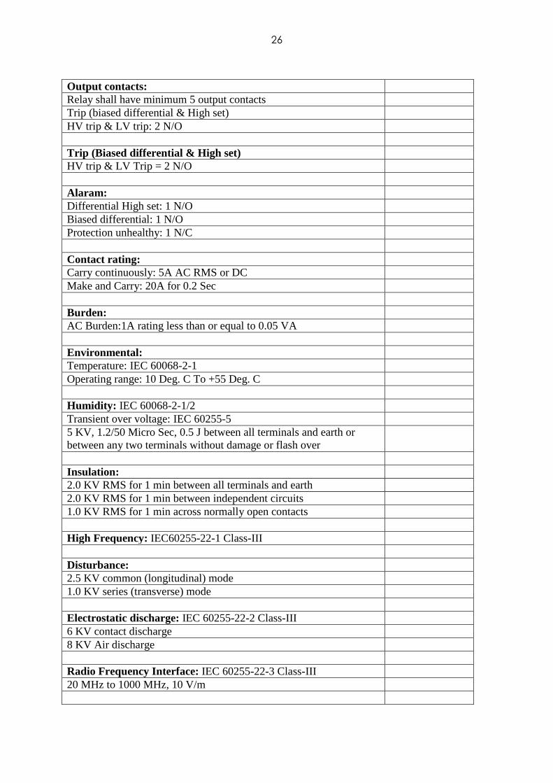
26
Output contacts: Relay shall have minimum 5 output contacts Trip (biased differential & High set) HV trip & LV trip: 2 N/O Trip (Biased differential & High set) HV trip & LV Trip = 2 N/O Alaram: Differential High set: 1 N/O Biased differential: 1 N/O Protection unhealthy: 1 N/C Contact rating: Carry continuously: 5A AC RMS or DC Make and Carry: 20A for 0.2 Sec Burden: AC Burden:1A rating less than or equal to 0.05 VA Environmental: Temperature: IEC 60068-2-1 Operating range: 10 Deg. C To +55 Deg. C Humidity: IEC 60068-2-1/2 Transient over voltage: IEC 60255-5 5 KV, 1.2/50 Micro Sec, 0.5 J between all terminals and earth or between any two terminals without damage or flash over
Insulation: 2.0 KV RMS for 1 min between all terminals and earth 2.0 KV RMS for 1 min between independent circuits 1.0 KV RMS for 1 min across normally open contacts High Frequency: IEC60255-22-1 Class-III Disturbance: 2.5 KV common (longitudinal) mode 1.0 KV series (transverse) mode Electrostatic discharge: IEC 60255-22-2 Class-III 6 KV contact discharge 8 KV Air discharge Radio Frequency Interface: IEC 60255-22-3 Class-III 20 MHz to 1000 MHz, 10 V/m

27
Fast transient: IEC 60255-22-4 Class-III 2 KV, 5/50 nos., 2.5 KHz repetitive Vibration (sinusoidal): IEC 60255-21-2 Class-I Shock & bump: IEC 60255-21-2 Class-1

28
V. GUARANTEED TECHNICAL PARTICULARS for NON DIRECTI ONAL NUMERICA 3 O/C + 1E/F (IDMTL WITH HIGHSET) RELAYS 1A & 5A (MULTIPLE SECONDARY CURRENT OPTION)
CT Input Rating - 1A &5A
(Multiple secondary current Option) Frequency - 50 Hz DC Auxiliary Supply
-
18V to 52 DC
Digital status Digital Inputs Digital Outputs
- -
2Nos 4Nos
Protection Settings Phase Fault Earth Fault High set Phase fault High set Earth Fault P/F Time Multiplier(IDMTL) E/F Time Multiplier(IDMTL) P/F Highset DTL E/F Highset DTL Reset Time
- - - - - - - - - - - - - -
5% to 200% (in step of 1%) 5% to 80%(in step of 1%) 50% to 2000%(in step of 5%) 50% to 2000%(in step of 5%) 0.01 to 1.5( in step of 0.005) 0.01 to 1.5( in step of 0.005) 0.02sec to 20sec( (in Step of 0.01sec) 0.02sec to 20sec (in Step of 0.01sec) 0 Sec to 20 Sec
1. Curve selection provision for IDMT 3 Sec. & 1.3 Sec(Extreme inverse, very inverse, Normal inverse, & High set instantaneous and High set with following IDMT Curves NI 1 (1.3 Sec), NI 3 3 Sec) EI,VI,DT,DTL Output Contacts The Relay has the following output contacts
Common Trip and Alarm Configurable outputs
- -
1 N/O +1 N/C 3 N/O

29
Contact Rating Carry Continuously Breaking capacity Making capacity
- - -
DC 6A 24V & 220V 200Watt Maximum 8A
LED 8 LEDs to view pickup and trip action Push Buttons For setting the relay Password facility Required Circuit Breaker failure protection Required Communication
RS 485 with modbus and USB
LED Indication
- - - -
LED ON LED PHASES L1,L2,L3 LED TRIP INDICATION(I>,I>>,Io>,Io>>)
16x2 Bright Alphanumeric LCD display for settings, readings and fault tripping data of minimum number 10 reports( with date and time stamping) Measurements
L1,L2,L3 and Earth
Burden AC Current input 5 A Rating 1 A Rating
- -
< 0.2VA < 0.1 VA
Auxiliary input Quiescent (typical)
3W (DC) 12VA (AC)
Environmental Temperature Operating range Storage range Humidity Transient Over voltage
As per IEC -As per IEC -(As per IEC) -40 Deg C to +85 Deg C As per IEC As per IEC 56 days at 400C and 95% RH
5Kv, 1.2/50 s, 0.5J between all terminals and earth or between any two terminal without damage or flashover

30
Insulation 2.0 KV rms for 1 min between all terminal and earth 2.0 KV rms for 1 min between independent circuits 1.0 KV rms for 1 min across normally open contacts
- As per IEC
High frequency Disturbance 2.5KV Common (Longitudinal) mode 1.0KV Series (Transverse) mode Electrostatic Discharge 6 KV Contact Discharge 8 KV Air Discharge
- -
As per IEC As per IEC
Radio Frequency Interference 20MHz to 1000MHz, 10 V/m
- As per IEC
Fast Transient 2KV 5/50ns, 2.5kHz repetitive Vibration (Sinusoidal) Shock and Bump
As per IEC As per IEC As per IEC
The relay to be supplied should also have the following features
1. Pre & Post Trip circuit supervision 2. Circuit Breaker Failure Protection 3. Multi-Shot Auto Reclose Function 4. Disturbance Recording facility 5. DC Healthy 6. The relay should have the communication port for compatibility of RS 485 with
modbus RTU and USB 7. Facility for four setting groups depending upon the status of BI shall be provided.
APPROVED MANUFACTURER/SUPPLIER
1. Ashida 2. CGL 3. CSPC 4. Alsthom 5. Siemens 6. Stelmec 7. ABB 8. Schneider 9. Easun

31
ANNEXURE – I STATIC TRIVECTOR METERS FOR USING ON 11 KV LV VCBS.
Three phase 4 wire Static Trivector Meter of reputed make of class 0.2S accuracy suitable to work on 110V/√3 AC, 50 Hz, -/1A for balanced and as well as unbalanced loads at all power factors i.e., Zero-lag-Unity-Zero lead to suit to be installed on 33 KV outdoor feeder panels and to suit the CT ranges indicated in Section-IV Schedule of materials. The meter should be capable of performing function of metering In all 4 quadrants, load survey etc. The meter shall conform to latest version of IS: 14697/99 CBIP Technical report 88/IEC 687 for accuracy and environmental and other relevant standards.
The meter should be capable of measuring the following electric parameters of poly phase supplies in all 4 quadrants at all power factors lagging or leading.
1. KWH Import and export
2. KVRH Import and export (lag & lead)
3. KVAH Import and export
4. Voltage of individual phases.
5. Currents in each individual phase.
6. Average Power factor.
7. Maximum demand (15 Minutes Integration)
8. Cumulative demand with No. of resets.
9. Real time.
10. Power off and power fully on and power partially on periods.
The meter should be capable of recording the full supply period, partial supply period and no supply period and display the same in separate tables with date, time and duration.
The meter should log the following parameters with 15 min, integration for the last 36 days in its memory card and it should be possible to transfer this data on to a base computer station through a DOS based hand held CMRI.
Parameters for logging shall be in import and export modes 1. KWH 2. Currents in all the three phases 3. KVARH 4. Voltage in all phases. The base computer shall give complete details of load survey particulars both in
numeric data form and in graphic form. Necessary software for invoking the base computer station should be provided.
The meter shall be provided with a galvonically isolated optical communication port (such as IEC-1107, PACT, ANSI etc.,) with removable cover and with locking arrangement so that it can be easily connected to a CMRI for data transfer or transfer of data through remote metering device such as modem/ multiflexer etc. The optical communication port shall also have sealing provision.
32
The meter shall also be provided with a sealable RS 232 and optical ports with DLMS open protocol which can used for AMR metering along with 9 pin D-type male connector so that it can be easily connected to a hand held meter reading instrument for data transfer or subsequently hooked to remote metering device such as modem etc. Necessary protocol software should be loaded into the CMRI and Base computer station of the Board for the purpose of reading and programming the specific make(s) of static meters and accepting data from hand held terminal/CMRI and processing, generating reports and won loading instructions from the base computer station to CMRI respectively.
The supplier is responsible for maintaining the security of the data extracted from the meters using manufacturers specific algorithms in the software upto down loading to the base computer station.
The meter shall have minimum legible 8-digit display of LCD. The display shall be digital type with non destructive readout and shall be possible to display legend for identification of display. The meter shall have facility of auto display mode where all parameters automatically scroll within the specified time. The number of parameters and the scrolling period shall be field programmable. It shall also be possible to read the parameters by a manual switch.
The non volatile memory shall have a minimum retention time of 10 years.
NOTE : All protocols are to be handed over to purchaser in advance and the memory map of the meter shall be furnished along with the tender.