09: ' # '7& *#0 & 8 - intechcdn.intechopen.com/pdfs-wm/35134.pdfstudy of...
TRANSCRIPT

3,350+OPEN ACCESS BOOKS
108,000+INTERNATIONAL
AUTHORS AND EDITORS115+ MILLION
DOWNLOADS
BOOKSDELIVERED TO
151 COUNTRIES
AUTHORS AMONG
TOP 1%MOST CITED SCIENTIST
12.2%AUTHORS AND EDITORS
FROM TOP 500 UNIVERSITIES
Selection of our books indexed in theBook Citation Index in Web of Science™
Core Collection (BKCI)
Chapter from the book Trends in Vital Food and Control EngineeringDownloaded from: http://www.intechopen.com/books/trends-in-vital-food-and-control-engineering
PUBLISHED BY
World's largest Science,Technology & Medicine
Open Access book publisher
Interested in publishing with IntechOpen?Contact us at [email protected]

11
Study of Evaluation Machinability of a Stainless Steels and Accompanying Phenomena in the Cutting Zone During Machining
Jozef Jurko1, Anton Panda1 and Tadeusz Zaborowski2 1Technical University of Košice,
2IBEN Wlkp 1Slovak Republic
2Poland
1. Introduction
The production process - cutting process (working materials) is currently still one of the fundamental technologies of production parts. It is therefore necessary that the cutting process was effective, the products are competitive mainly in terms of production costs. If we consider the technological system M-machine, T-tool, W-workpiece and F-fixture, each element of this system has a different percentage of production costs. But the most important reason for the need of productive machining production time is that it is necessary to always use the best. This is a guide to success for a large part of production processes, ie maximum number of products per unit of time. Especially during operation, for variations in technological progress in production, there are significant changes in the cost per piece produced parts. Currently we can apply several alternatives for increasing productivity cutting process:
a. Alternative: Investment in new CNC machine to ensure the production program is especially important that this machine can significantly increase performance and speed aside, to improve the conditions of production and thereby ensuring returns in the coming years, and profit.
b. Alternatives: Improving the cutting process is a way of improving the cutting process continuously, provided the correct application of cutting tools - for defined machining conditions and for a defined set of M-F-W technology. In comparison with a) this solution is inexpensive (compared to the price of a new machine).
Developments in the machining method is dynamic and applied a decade or five years ago are largely already non-progressive. Seeing similar developments in the production of advanced cutting tools (for a defined structure for the defined basic materials for defined surface layer). On this basis, it is possible to achieve a productive day as production. one operating the machine, especially the change of applied cutting tools. Non-use benefits of development and inability to correct application of advanced cutting tools may be one outcome, namely: untapped potential for increasing its profits and competitiveness. Nature of the cutting process is that there is a complete plastic deformation separated workpiece
www.intechopen.com

Trends in Vital Food and Control Engineering
236
(chip-form) by interaction T (cutting tool) and W (workpiece), defined in terms of a defined technological system M-F. Application of advanced cutting tools to be mainly in terms of economy: faster return on investment (new machinery), improve performance (old machine) and labor productivity service. Currently one of the cost items, which affects the production costs for 1 piece parts is heading: the cost of cutting tool. Every company in the total cost to produce one piece of different components defines the percentage of the cost of cutting tool. Although the costs of cutting tool, the proportion of the total cost to produce one piece of a few parts percentage, have a significant impact mainly on:
1. Cutting process - interaction (cutting tool-workpiece) - impact on the overall result (damage, surface roughness, defects, errors, change in mechanical properties), machined surfaces of the parts.
2. Hours of downtime of the machine - damaged cutting tool (its durability, respectively life, to ensure logistics system - storage, maintenance, service.
3. The number of necessary operations - change in technological progress, quality progressive tool can provide cost savings (production of precise holes - drilling, reaming).
4. Time, which parts must remain in the company. 5. Number of cutting tools, which must be available (logistics, availability).
At the cost mainly affects: labor, machinery, tooling, material, overhead and savings. Automated production of, in the sense of, machine production has characteristic features: a reduction of production costs, stimulation of the development of cutting tools, and changes in the construction of machine tools, all of which work against the creation of optimal technological methods, which thrusts the technological process of cutting into a more important position. These trends confirm that the cutting process remains one of the basic manufacturing technologies. A condition of the economic usage of modern, automated programmed machines is the optimal course of the cutting process, i.e. the use of optimal work conditions. A summary of optimal work conditions requires knowledge of the laws of cutting theory and knowledge of the practical conditions of their application.
2. Stainless steels
Stainless steels are distinguished by many features, including:
inherent resistance to corrosion and heat under given conditions,
aesthetic factors, hygienic characteristics, ease of cleaning and sterilization,
a high ratio of strength to weight,
low magnetic permeability.
Stainless steels are fundamentally subdivided by their chemical composition and metallographic structure. Austenitic steels are the most extensive and thus the most important category of stainless steels. Several kinds of these steels are known, which differ among themselves in their carbon, nickel, and sometimes in their titanium content. Titanium is an important element, which increases the steel’s resistance to intercrystalline corrosion.
Current developments in stainless steels is divided into three directions:
1. Development of several species containing up to 0.02% carbon 2. Development of new types of nitrogen added as an effective alloying elements 3. Development of steel with a further increase in the level of corrosion resistance.
www.intechopen.com

Study of Evaluation Machinability of a Stainless Steels and Accompanying Phenomena in the Cutting Zone During Machining
237
The basic chemical elements of austenitic steels are resistant to high temperatures and loads chromium-nickel-chromium and nickel. To increase the added resistant to high temperatures and loads tungsten-W (about 2%), molybdenum, Mo (1-3%), ever-Nb niobium, titanium Ti, vanadium V, N-nitrogen. Chromium content varies from 12 to 20%. Chromium belongs to the group the ferrite formed elements to completely conclude the gamma region. In a purely binary system of iron (Fe) - chromium (Cr) achieves homogeneous area of gamma at 1075 ° C up to 10.6% chromium content. In technical alloys may be limits to move to higher chromium content, because it had a small amount of carbon and nitrogen gamma significantly expand the area. At high content of Cr in the binary system Fe - Cr appears fragile intermediate sigma phase with variable composition and hardness about 100 HV, which is stable up to temperatures of 815 ° C. When cooling is falling apart at 460 ° C eutectoid response to a phase , ´ the solid solution of Fe - Cr with higher iron content and higher content of chromium. Today, most assumed that the fragility of the high-chromium steels causes the coexistence of these phases, and not the sigma phase. The nickel content is higher than in austenitic steels 18/9, it must balance the impact the ferrite formed elements and avoid elimination phase which reduces impact strength. For alloys Fe-Ni could be envisaged with a large thermal hysteresis. For a content of about 7% nickel austenite transformation takes place even under normal conditions of cooling (especially the cooling rate) free diffusion, ie sliding mechanism similar to alloys of iron and manganese. According by Lavesa Fe2Mo phase.Molybdenum increases resistant to high temperatures and loads, however, supports the formation of undesirable phases and Vanadium increases the stress-rupture, especially at lower temperatures. At 700 ° C has little influence vanadium. The additive is especially effective in the presence of nitrogen, since the dislocation creep precipitated vanadium nitrides, whose gross even after long soaking at a temperature only slightly. Carbon inhibits secretion of delta ferrite and increases the mechanical properties. If it is excluded in the basic matrix precipitates as M23 (C, N)6, or M23 (C, B)6, slows the flow. In an unstable steels inhibits formation of sigma phase, which is produced only when the greater part is excreted as carbon carbide. Carbon suppresses the formation phase Fe18Cr6Mo or chi (Fe, Ni)18Cr9Mo4. Some Heat resistant austenitic steel containing a small amount of niobium or titanium with carbon are stable carbide. The highest stress-rupture of steel to the ratio Ti/C from 0.8 to 1.2. Similarly affects resistant to high temperatures and loads niobium, the optimal ratio nNb:NC is lower and more dependent on test temperature and time. The disadvantage of steel with niobium is their tendency to crack in the weld area and a decrease in toughness after long lasting working temperature. To increase the yield strength of hot, ultimate strength, respectively. stress-rupture is added to austenitic steels unstabilised small amounts of nitrogen, which slows down the diffusion rate of carbon and thus the elimination of coagulation and carbides M23C6 and other intermetallic phases. Because at the same time reduces the rate of substitutional alloying elements in grain boundaries, extended incubation period of precipitation. Solubility of nitrogen in the steel matrix with a maximum of 0.003% C at 1150 °C is about 0.30% at 600 to 650 ° C decreases to 0.005%. Admixture of nitrogen to 0.14% increases resistant to high temperatures and loadsaustenitic steels containing up to 0.03% as well, that their properties aligned carbon steel containing 0.06 to 0.09%.
2.1 Categories of stainless steels
Austenitic-A family of alloys containing chromium and nickel (and manganese and nitrogen when nickel levels are reduced), generally built around the type 302 chemistry of 18% Cr, 8% Ni, and balance mostly Fe. These alloys are not hardenable by heat treatment.
www.intechopen.com

Trends in Vital Food and Control Engineering
238
Ferritic - This group of alloys generally containing only chromium, with the balance mostly
Fe, are based upon the type 430 composition of 17% Cr. These alloys are somewhat less
ductile than the austenitic types and again are not hardenable by heat treatment.
Martensitic - The members of this family of stainless steels may be hardened and tempered
just like alloy steels. Their basic building block is type 410 which consists of 12% Cr, 0.12%
C, and balance mostly Fe.
Precipitation-Hardening - These alloys generally contain Cr and less than 8% Ni, with other
elements in small amounts. As the name implies, they are hardenable by heat treatment.
Duplex - This is a stainless steel alloy group, or family, with two distinct microstructure
phases, ferrite and austenite. The Duplex alloys have greater resistance to chloride stress
corrosion cracking and higher strength than the other austenitic or ferritic grades.
Classification of stainless steels defines also diagram on base equivalent Ni and Cr by Fig.1.
Equations 1 and 2 described of equivalent Ni and Cr.
Fig. 1. Schäeffler diagram for Stainless steels, zone 1-structure ferrite, martenzite, zone 2-structure duplex (austenite, ferrite), zone 3-structure austenite, zone 4-structure ferrite
NiE % Ni 30x % C 0,5x % Mn (1)
CrE % Cr % Mo 1,5x % Si 0,5x% Nb (2)
In Table 1 are mentioned mostly applied stainless steels.
www.intechopen.com

Study of Evaluation Machinability of a Stainless Steels and Accompanying Phenomena in the Cutting Zone During Machining
239
Alloy C Mn P S Si Cr Ni Mo Others
301 0.15 2.00 0.045 0.030 1.00 17.00 7.00 - -
302 0.15 2.00 0.045 0.030 1.00 18.00 9.00 - -
303 0.15 2.00 0.20 0.15 1.00 18.00 9.00 0.60 -
303Se 0.15 2.00 0.20 0.06 1.00 18.00 9.00 0.60 0.15Se
304 0.08 2.00 0.045 0.030 1.00 19.00 9.25 - -
304L 0.03 2.00 0.045 0.030 1.00 19.00 10.0 - -
309S 0.08 2.00 0.045 0.030 0.75 23.00 13.5 - -
310S 0.08 2.00 0.045 0.030 1.50 25.00 20.5 - -
316 0.08 2.00 0.045 0.030 1.00 17.00 12.0 2.5 -
316L 0.03 2.00 0.045 0.030 1.00 17.00 12.0 2.5 -
317 0.08 2.00 0.045 0.030 1.00 19.00 13.0 3.5 -
317L 0.03 2.00 0.045 0.030 1.00 19.00 13.0 3.5 -
321 0.08 2.00 0.045 0.030 1.00 18.00 10.5 - Ti 5 X C
329 0.10 2.00 0.045 0.030 1.00 27.50 4.5 1.50 -
347 0.08 2.00 0.045 0.030 1.00 18.00 11.0 - Cb+Ta 10 X C
409 0.08 1.00 0.045 0.045 1.00 11.50 - - Ti 6 x C
410 0.15 1.00 0.040 0.030 1.00 12.50 - - -
416 0.15 1.25 0.040 - 1.00 13.00 - 0.60 S =0.15 min.
416Se 0.15 1.25 0.060 0.060 1.00 13.00 - - 0.15 Se
420 0.15 min. 1.00 0.040 0.030 1.00 13.00 - - -
430 0.12 1.00 0.040 0.030 1.00 17.00 - - -
440C 1.00 1.00 0.040 0.030 1.00 17.00 - - -
904L 0.02 2.00 0.045 0.035 1.00 21.00 25.5 4.5 Cu 1.5
17-4 PH 0.07 1.00 0.045 0.035 1.00 16.5 5.5 - Cu 3-5, 0.4 Al
17-7 PH 0.09 1.00 0.045 0.035 1.00 17.0 7.0 - 0.75-1.5 Al
Table 1. Chemical composition of the Stainless steels
3. Machining of stainless steels
Austenitic stainless steels are produced with graded carbon content. The content of chromium steels in this group of about 18% nickel content is tailored to the requirement that the steel structure was largely austenite. Minor phases present in the structure are made of ferrite and carbides of chromium δ mainly M23C6 type. Austenite is in this group of steels stable even at temperatures well below freezing. Mechanical properties in the solvating annealing, where part of the solution passes into the carbide, depending on the content carbon. Machining austenitic steels is more difficult compared with the low and medium alloy steels.
High strength, low thermal conductivity, high ductility and a tendency to high firming austenitic stainless steels are the main factors that make their machinability difficult. Most
www.intechopen.com

Trends in Vital Food and Control Engineering
240
difficult place to drill deep holes with small diameter, shown Fig.2. Any method of cutting process leaves the surface of certain characteristics and form of a specific surface condition. On the surface of the cut and formed macroprofil and microprofil of surfaces. Force effects a working tool for cutting a thin surface layer beneath the surface of the deformed section. As a result of deformation heating and heat, which always accompanies the process of cutting, are the tensions in this layer and change its physical and mechanical properties.
Fig. 2. Drilling process
Problem of machining austenitic steels-austenitic stainless steels are characterized by high toughness, low thermal conductivity and a high degree of hardening of machined surface after machining. In terms the machinability of stainless steel is of great importance especially bonding surface finish. Low thermal conductivity causes adverse creation and shaping of particles in the editing plane, and therefore the material of cutting tools should be applied to sintered carbides. Austenitic steels are more prone to plastic deformation due to the large number of slip systems. Hardening of the machined surface (evaluated by measuring hardness) is the result of transformation of metastable austenite. For working metal, should be seen as a process of plastic deformation. Plastic deformation in relation to the cut surface of an object can take different forms and plastic (hardening), elastic-plastic or elastic. For a group very hard materials, this form of plastic deformation only. On the surface of the section, is of key importance, the thickness of plastically deformed material surface. The various levels of plastically deformed material thickness is a form of distortion varies. Aim of this paper is to present research findings determine the size of the zone of plastic deformation near the surface of the holes drilled by methods of light and electron microscopy and characterized by measuring the intensity of hardening the microhardness values of plastically deformed zone. The paper presents results of deformation of material under the layer surface finish when drilling austenitic stainless steel 1.4303.
According to different authors, very hard materials have ductility that is fifty percent greater than convetional materials, but handle heating more poorly. The specific electrical resistance depends on the chemical composition, not on the structure of the material. For very hard materials it is also characteristic that they have a low thermal conductivity, which
www.intechopen.com

Study of Evaluation Machinability of a Stainless Steels and Accompanying Phenomena in the Cutting Zone During Machining
241
is mostly a function of the chemical composition. It is important to stress that, as to their mechanical, physical and chemical characteristics, each very hard materials should be studied independently. Working is the result of a mutual interaction of the cutting tool and the workpiece that is accompanied by a number of phenomena that produce the synergic effect. Chip production is described through the plasticity theory. The field of slip lines intervenes with the area of the plastic deformation, the machined surface and the chip. Slip lines represent a durable, highly intense deformation. During the interaction of the cutting elements and the workpiece and due to heat, wearing takes place in the cutting area, because friction depends on the interaction of pure metal surfaces between the frontal surface of the cutting part of the tool and the chip, as it is stated. Wearing is a synergic effect of factors that cause the change of weight, volume or the change of dimensions on the cutting part of the tool. The area of the slip contact has an important role during cutting. The creation of flow zone on the frontal and back surface of the tool called the scab, is one of phenomena resulting from the interaction of the workpiece and the cutting edge of the tool. The order of phases of the scab as a periodic phenomenon that mostly negatively influences the process of cutting. Figure 3 and Figure 4 each photograph includes the information of the thermo-plastic deformation. The paper described verification of CAD systems applied by analysis of drilling tools. Analysis of tool life is very important for proces effectivity.
There is a tendency in the field of machined materials towards stainless steels with higher strength and higher corrosion resistance. Duplex stainless steels are often applied (Schintlmeister & Wallgram). High-efficiency machining and the machinability of high-strength stainless steels are considered to be the most important future trends affecting machining operations. Duplex stainless steels have a lower nickel content than austenitic stainless steels, and an austenite plus ferrite structure. Increased strength with enhanced properties for service in a corrosive environment provides difficulties from a machinability point of view. The characteristics of stainless steels raised from the austenitic structure are high toughness, low thermal conductivity and high workhardening co-efficient (Peckner & Bernstein). From a machinability point of view the most important characteristic is the workhardening. Because of the low thermal conductivity, the chips are formed on the basis of catastrophic failure in narrow shear surfaces (Dolinšek). When carbide tools are used these characteristics cause the formation of BUE and low values of tool life. Cutting forces are also increased and the unfavourable formation of tough chips appears (Dolinšek). Tool materials, such as CVD-coated (Chemical Vapour Deposition) with hard Al2O3 coatings, are often preferred (Belejchak). The need for a hard tool surface coating is especially required when HIPed stainless steels containing hard inclusions are to be machined. Near-equiatomic nickel-titanium alloys (NiTi) have many attractive properties for engineering applications, such as pseudo-elasticity and good cavitation resistivity, in addition to their more well-known shape memory properties (Li & Sun, Starosvetsky & Gotman). In drilling stainless steel with a pseudo-elastic coating material, machinability difficulties are involved with the pseudo-elastic properties of the coating material. Nevertheless, both technical and commercial limitations arise when NiTi is considered as a material for large engineering components. Consequently, interest in NiTi-coating technologies, for example for stainless steels, is on the rise. The cutting process of NiTi-based shape memory alloys is influenced by their high ductility and high degree of workhardening, and the unconventional strain-stress behaviour (Weinert & Petzoldt). The investigation of machining austenitic stainless steels in different cutting processes has been initiated by industry, where the need for effective tools
www.intechopen.com

Trends in Vital Food and Control Engineering
242
and demands for reliable data on cutting parameters extends far beyond the experiences or recommendations given by tool producers (Dolinšek). The machinability studies are often carried out by vcT-tests in turning, milling and drilling operations. Tool wear is studied by using optical microscopy to define the amount of flank and crater wear. The interaction between tool and chip can be effectively studied using SEM. There are several tendencies affecting the technology and methods used in the metalworking industry. Highly efficient machining strategies are used, and HEM (High Efficiency Machining) is used as a machining method. In HEM machine tools, modern tools are used with sufficient cutting parameters. HEM focuses on optimising cutting efficiency to maximise material removal rate. Compared to HSM (High Speed Milling), lower spindle speeds and increased chip thicknesses are used. The modern tools and tool materials available for this research were specifically designed cutting tools for HEM machine tools. The machine tool reliability and productivity is controlled by optimising machining parameter selection and acceptable and adequate sufficient parameters are used. Also, nowadays modern machine tools are very complex mechatronical systems and their capability and efficiency are mainly determined by their kinematics, structural dynamics, computer numerical control system and the machining process (Altintas et al., and Weck et al.).
For materials of the cutting tools are allocated to three variables, which can determine the
choice of material, cutting tool in a machining operation:
wear resistance,
toughness, respectively. resistance to fracture and deformation,
wear resistance at elevated temperature.
4. Examples results from experiments
4.1 Example 1
The material were selected for the purposes of the experiment X4Cr19Ni9 stainless steel,
which were then compared to X03Cr16Ni8 steel. The chemical composition of machined
materials is reported in Table 2.
Element C Cr Ni Mn Ti Mo Si N P S
X03Cr16Ni8 0.3 16.0 7.5 1.8 - - 0.36 - 0.04 0.03
X4Cr19Ni9 0.04 19.0 9.0 1.2 0.4 0.09 0.30 0.04 0.03 0.03
Table 2. Chemical composition of stainless steels in [wt.%]
X03Cr16Ni8 steel microstructure contains larger quantities of complex carbides.; these are
generated along grain edges when compared to X4Cr19Ni9 steel. For the purposes of the
experiments, the applied technical system was: Machine: Chiron FZ12 CNC. Tool: Screw
drill with diameter d=7.0 mm – new cutting area structure in sintered carbide. Tool fixture:
high-precision hydraulic clamping head. Workpiece: the following materials were employed
for the purposes of experimental measurements: X03Cr16Ni8 steel, X4Cr19Ni9 steel with
low carbon content. Samples with the following dimensions were used for the purposes of
experimental measurements: bxhx (40x40x200) mm. Cutting conditions: cutting speed in
interval vc= 40-60 m per min, feed in interval f=0.01-0.08 mm per rev. Machining method:
www.intechopen.com

Study of Evaluation Machinability of a Stainless Steels and Accompanying Phenomena in the Cutting Zone During Machining
243
Dry Machining. With regard to cutting tool life, the following criterion was applied: VBk=0.2
mm. Measurement was carried out by means of an optical microscope without extracting
the cutting tool from the clamping fixture. The cutting tools and fragments were analyzed
using an electron microscope (SEM).
The result of cutting tool life assessment is T-vc dependence. Analysis of T-vc dependence
used a tool with a new cutting area; when drilling X03Cr16Ni8 steel at 40 m per min cutting
speed, the following drilling length was achieved: 4.5 m (at feed f=0.065 mm per rev.). Due
to the increased cutting speed of 60 m per min, drilling length was reduced to 0.9 m. Tool
life was reduced from 16 minutes to 4.5 minutes. When drilling X4Cr19Ni9 steel at 40 m per
min cutting speed, the following drilling length was achieved: 4.0 m (at feed f=0.065 mm per
rev.). Due to the increased cutting speed of 60 m per min, drilling length was reduced to 1.0
m. Tool life was reduced from 9 minutes to 3.0 minutes. When comparing the execution of
holes for cutting tools into X03Cr16Ni8 steel, we observed that tool life was increased by 36
% compared to X4Cr19Ni9 steel. The higher percentage of carbon does influence the
increase of carbide formation, especially along grain edges; this fact has an impact on
cutting tool lifes. By decreasing carbon content we eliminate carbide formation and
therefore we increase cutting tool life.
The tendency to generate built-up edges was more significant in the case of X4Cr19Ni9 steel than in the case of X03Cr16Ni8 steel. One example of BUE formation for X4Cr19Ni9 steel during drilling followed these cutting conditions: cutting speed vc=45 m per min, feed f=0.065 mm per rev. A cutting speed increase has an impact on BUE formation over the front area. By comparing the steels it was ascertained that in the case of X03Cr16Ni8 steel the corner was not worn (unlike X4Cr19Ni9 steel). BUE formation over the face area and cutting part shape (geometry) influence the chipping on the cutting edge. An electron microscope was used for wear analysis for sintered carbide cutting tools (SEM - Scanning Electron Microscopy). Qualitative and quantitative workpiece modifications do occur in the cutting zone. With regard to circumstances in the cutting zone, it is important to be aware of the input features of interacting objects (tool and workpiece) as well as of conditions influencing such interaction from the point of view of machining equipment. Output elements generated from the cutting: a workpiece with a machined surface, and tool with possible cutting area damage. For the purposes of analysis of the creation and shaping of chips, the samples were examined using an SEM according to the following cutting conditions: cutting speed vc=40 and 60 m per min. X03Cr16Ni8 steel chips; X4Cr19Ni9 steel chips are illustrated; These figures illustrate the chip surfaces from their concave and convex sides. Cutting tool wear increased when cutting speed rose from 40 to 60 m per min. At this cutting speed interval it was possible to observe a tendency to make larger BUE in the case of X03Cr16Ni8 steel compared to X4Cr19Ni9 steel. Here we can observe traces/grooves as a result of the interaction between the chip and the front area of the tool. The concave side of the chip (dished chip) reported in Fig.3 shows a modification of the thickness of the elements/flakes (lamellae) when cutting speed increased. The higher tendency of BUE formation with X03Cr16Ni8 steel can be compared against the fragment surface (convex shape). Worse (reduced) machinability (resulting from the comparison of X03Cr16Ni8 and X4Cr19Ni9) could be caused by the irregular tooth-like endings on the convex (protuberant) sides of the chip. When comparing the chips with X03Cr16Ni8 and X4Cr19Ni9, it is possible to observe grooves (depressions) and protruding material. Chip shaping is influenced by structurally
www.intechopen.com

Trends in Vital Food and Control Engineering
244
unstable effects. Tool wear occurred continuously for X03Cr16Ni8 steel with the use of a cutting tool in dry machining. In this respect, at increasing cutting speeds tool plastic deformation takes place with gradual laminar flaking of the surface on the cutting tool (Fig. 3a) and with destruction of the coat (frittering) over the front area (Fig.3b); tool wear is influenced by the formation of built-up edges and by coat flaking.
(a) (b)
Fig. 3. Helical drill - characteristical wear in cutting part. (a) Coat damage on dorsal area - gradual coat laminar flaking on cutting tool. (b) Coat damage - destruction (frittering) on front area
Fig. 4. Relation between machined workpiece micro-hardness and cutting speed when drilling holes into X03Cr16Ni8 and X4Cr19Ni9 steels, with feed 0.065 mm per rev.
www.intechopen.com

Study of Evaluation Machinability of a Stainless Steels and Accompanying Phenomena in the Cutting Zone During Machining
245
Stainless steels are influenced by charging due to intensive mechanical reinforcement during
machining. The examination of reinforced surfaces can be carried out by measuring the
micro-hardness of the bottom part of the fragment; indeed, the bottom part of the fragment
can be considered as the most deformed fragment zone. The results of micro-hardness
examination are reported in Fig. 4, these results are as follows: X03Cr16Ni8 steel: fragments
are strongly deformed compared to X4Cr19Ni9 steel. Austenite fragment, bottom part, vc=60
m per min, 310 HV (20 g), if the bottom part of the fragment is measured: austenite 240 HV
(20 g). 2. X4Cr19Ni9 steel: vc=45 m per min, austenite microhardness 230 HV (20 g), if the
bottom part of the fragment is measured: austenite 234 HV (20 g). The results presented in
this article can be summarized as stated in the following main conclusions for the sake of
comparison:
1. Machinability of X03Cr16Ni8 steel and X4Cr19Ni9 steel is influenced by the formation
of BUE. X03Cr16Ni8 steel tends to form more BUE than X4Cr19Ni9 steel
2. Tool life (for the applied cutting tool) is between 4.5 min. and 12 min., when drilling
X4Cr19Ni9 steel.
3. BUE formation is caused by adhesive wear; in terms of cohesion, this fact indicates that
the above mentioned mechanism is likely to be the predominant mechanism in the
damaging process of sintered carbide tools when drilling into X4Cr19Ni9 steel.
4.2 Example 2
During the drilling simulation, the cutting edges of the drill bit are shearing the workpiece
material at high speeds which separate the material from the workpiece by chip formation.
The material separation criterion for machining has been a topic of interest in the
development of the theory of finite element modeling of machining. Initially, a parting line
model was assumed to simplify the simulation process. This model assumed a small crack
existed in the material and the chip was separated from the workpiece in a predetermined
“unzipping” fashion. Eventually, the maximum plastic strain model was proposed and this
criterion has been adopted by most FEM models. This maximum plastic strain model
assumes that material separation occurs when an element reaches a critical plastic strain for
the material model of the workpiece. The element is then split into two elements and a chip
is formed. One can argue whether drilling actually produces smooth separation. Regardless,
the maximum plastic strain criterion has been implemented and this has been the most
accepted method of failure criteria to model burr formation in drilling. Historically, the two
standard FEM meshes are Eulerian and Lagrangian. There are also combinations such as the
Arbitrary Lagrangian Eulerian (ALE) and the Coupled Eulerian Lagrangian (CEL) meshes.
Although the Lagrangian mesh is not as comprehensive as the Eulerian mesh, it has much
better simulation cycle times as a result. Lagrangian mesh in simulating drilling processes is
the ability to know the entire time history of the key variables at every point during the
simulation. That means, if a simulation crashes for any reason, a new simulation can start
where the crashed simulation stopped. This is particularly useful because nearly every
simulation has some sort of problem during the run. This is possible because the Lagrangian
mesh is reformulated at nearly every time step, in order to manage the deformation of the
material. Several different types of machining operations can be accomplished with
www.intechopen.com

Trends in Vital Food and Control Engineering
246
Proengineer including drilling, turning, and milling. If a tool geometry can be modeled, the
machining operation can be simulated. One of the most difficult problems faced with
modeling drilling operations is obtaining an accurate model of a drill bit. More authors both
present how this can be done and the latter developed a program to do this quickly and
easily. Fig. 5,Fig. 6, Fig.7., Fig. 8., Fig.9., Fig. 10. each photograph includes the information of the
thermo-plastic deformation. The paper described verification of CAD systems applied by
analysis of drilling tools. Analysis of tool life is very important for proces effectivity.
(a)
(b)
Fig. 5. Modeling of screw drill. (a) Tool wear- stress on the cutting edge. (b) Tool wear - plastic deformation on the cutting edge
www.intechopen.com

Study of Evaluation Machinability of a Stainless Steels and Accompanying Phenomena in the Cutting Zone During Machining
247
(a)
(b)
Fig. 6. Modeling of screw drill with two margins. (a) Tool wear- stress on the cutting edge. (b) Tool wear - plastic deformation on the cutting edge
www.intechopen.com

Trends in Vital Food and Control Engineering
248
Fig. 7. Modeling of screw drill - Tool wear- stress on the cutting edge
Fig. 8. Modeling of screw drill - Load on the cutting part
Fig. 9. Modeling of screw drill with two margins - stress on the cutting part
www.intechopen.com

Study of Evaluation Machinability of a Stainless Steels and Accompanying Phenomena in the Cutting Zone During Machining
249
Fig. 10. Modeling of screw drill with two margins - Load on the cutting part
The cutting edge of an insert in a finishing operation is worn out when it can no longer generate a certain surface texture. Not a lot of wear is needed along a very small part of the insert nose for the edge of an insert to need changing. In a roughing operation wear develops along a lot longer part of the edge and considerably more wear can be tolerated as there are no surface texture limitations and accuracy is not close. The tool-life may be limited when the edge looses its chip control ability or when the wear pattern has developed to a stage when the risk for edge breakdown is imminent.
4.3 Example 3
For the experiments was applied technological system machine-tool-workpiece-fixture: CNC Chiron FZ12, helical drill with a diameter d=7.0 mm, the new design of the cutting edge with uncoated cemented carbide. Fixture for the cutting tool: high precision hydraulic clamping head, the workpiece fixture: mechanical vise. Workpiece: stainless steel-austenitic X4Cr17Ni8 steel. The materials to be machined were type of a new austenitic stainless steels with chemical composition listed in Tab.3. Experiments were used for sample size hxbxl (30x30x200) mm, for drilling holes 15 mm in depth and definition to the evaluation of internal machined surface. Cutting conditions: cutting speed of vc=interval of 20-60 m/min, feed f=interval from 0.01 to 0.08 mm per revolution, depth of cut ap=3.5 mm. Method of machining and dry machining. Workpieces of X4Cr17Ni8 steel, obtained by drilling, were analyzed for electron microscopy. To deformed the steel-hardening layer, was rated a hard layer width from the cut surface, a hard layer microhardness, and surface finish has been rated Ra surface roughness and surface morphology.
C Cr Ni Mn Si P Ti S
0.04 17.2 8.2 1.6 0.6 0.04 0.06 0.03
Table 3. Chemical composition of stainless steels in wt [%]
The parameters of the process of drilling holes and dimensional characteristics of the drill
are: T1(feed is 0.01 mm, cutting speed is 20 m/min., d=7 mm, angle 2κr=135°), T2 (feed is
0.065 mm, cutting speed is 35 m/min., d=7 mm, angle 2κr=135°), T3 (feed is 0.08 mm, cutting
www.intechopen.com

Trends in Vital Food and Control Engineering
250
speed is 40 m/min., d=7 mm, angle 2κr=135°). Workpieces for metallographic analysis were
collected spark so that the plane metallographic sections axis hole. Subsequently, the
workpieces were prepared and ready in dentacryle conventional metallographic
procedures. For purposes of analysis has been used light microscopy experimental
technique: an inverted metallographic microscope for observation in polarized light and
differential interference contrast using (DIC). To verify the value of the depth of plastically
deformed zones around the drilled holes (determined by light microscopy) technique was
used for scanning electron microscopy - with a JEOL JSM 7000F autoemission nozzle.
Microhardness plastically deformed zone was set at a distance of 60 m for austenitic steel
X4Cr17Ni8 steel. Methods of light and scanning electron microscopy was specified range
plastically deformed zones in drill holes under the surface of the material X4Cr17Ni8 steel.
Local hardening plastically defor-med zone around the drill holes was characterized by
measuring the microhardness LM 700 AT micro-hardness with a load of 0.2452 N. For more
information about local hardening deformed zone in the E position drill holes were obtained
by measuring the indentation hardness apparatus Nanoindentation Hardness Tester - TTX
NHT2 CSM method, where the grow monotonous load is superimposed small sinusoidal
load. Measurement parameters Berkovich indenter types were: feed rate indenter 3000
nm/min, a maximum load of 100 mN, loading and unloading speed 200 mN/min, sinus
frequency 20 Hz, amplitude sinusoidal load of 5 mN, stay to the maximum load of 10 s.
Indentation measurements were in the position E hole. Analyses of samples plastically
deformed layers under the surface of machined steel X4Cr17Ni8 steel can confirm these
allegations. Autors indicates that for X4Cr17Ni8 steel, resizing a layer of plastic deformation
is related mainly to the material structure and properties of austenitic grain size.
Fig. 11. Plastic deformation of the surface, local plastic deformation in austenitic grain-hardening surface, zone of hole F
Hardening uneven layer width from 30 m to 550 m, example as shown in Fig.11, generated by the cutting conditions of 50 m/min to 60 m/min and feeds on larger than 0.06 mm. Plastic deformation of the machined surface has the character in Fig.12.
www.intechopen.com

Study of Evaluation Machinability of a Stainless Steels and Accompanying Phenomena in the Cutting Zone During Machining
251
Fig. 12. Plastic deformation of the surface to a depth of 220 m, local plastic deformation in the austenitic grain, zone of hole H
To plastic deformation occurs under the surface finish and the local austenite grains. At a
cutting speed of 30 m/min to 45 m/min and feeds from 0.04 mm to 0.08 mm width was
measured to strengthen the layers from 20 m to 68 m, which is plastically deformed
smallest layer, as shown Fig.13. Under these conditions, the cutting width was measured to
be uniform solidified layer. At the same time claim autor2 confirmed that this is true for
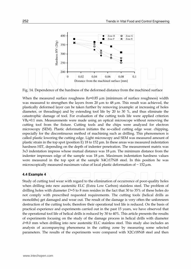
smaller austenite grains (~to 80 m). Hardness HV (20g) in plastically deformed layer after
drilling X4Cr17Ni8 steel Fig.14 shows. For the evaluation of machined surface was
measured roughness Ra=0.85 m at a cutting speed of 50 m/min and feed is 0.04 mm.
Fig. 13. Dependence of width of the deformed area of cutting speed and different feed, zone of hole F
www.intechopen.com
Trends in Vital Food and Control Engineering
252
200
250
300
350
400
0 0,02 0,04 0,06 0,08 0,1
Distance from the machined surface [mm]
Har
dn
ess
HV
(2
0g
)
Zone H Zone G
Zone F Zone E
Fig. 14. Dependence of the hardness of the deformed distance from the machined surface
When the measured surface roughness Ra=0.85 m (minimum of surface roughness) width
was measured to strengthen the layers from 20 m to 48 m. This result was achieved, the plastically deformed layer can be taken further by removing (example: at increasing of holes diameter, or threadings) and by extending tool life by 20 to 30 %, and thus eliminate the catastrophic damage of tool. For evaluation of the cutting tools life were applied criterion VBk=0.1 mm. Measurements were made using an optical microscope without removing the cutting tool from the fixture. Cutting tools and the chips were analyzed for electron microscopy (SEM). Plastic deformation initiates the so-called cutting edge wear. chipping, especially for the discontinuous method of machining such as drilling. This phenomenon is called plastic lowering the cutting edge. Light microscopy and SEM was measured amount of plastic strain in the top spot (position E) 18 to 152 μm. In these areas was measured indentation hardness HIT, depending on the depth of indenter penetration. The measurement matrix was
3x3 indentation impress whose mutual distance was 18 m. The minimum distance from the
indenter impresses edge of the sample was 18 m. Maximum indentation hardness values were measured in the top spot at the sample X4Cr17Ni8 steel. In this position he was
microscopically measured maximum value of local plastic deformation of ~ 152 m.
4.4 Example 4
Study of cutting tool wear with regard to the elimination of occurrence of poor-quality holes
when drilling into new austenitic ELC (Extra Low Carbon) stainless steel. The problem of
drilling holes with diameter D=5 to 8 mm resides in the fact that 30 to 35% of these holes do
not comply with prescribed requested requirements. The cutting tools (helical drills as
monoliths) get damaged and wear out. The result of the damage is very often the unforeseen
destruction of the cutting tools; therefore their operational tool life is reduced. On the basis of
practical experience and experiments carried out in the past 15 years, we have observed that
the operational tool life of helical drills is reduced by 30 to 40%. This article presents the results
of experiments focusing on the study of the damage process in helical drills with diameter
d=8.0 mm when drilling into new austenitic ELC stainless steel. This study also includes an
analysis of accompanying phenomena in the cutting zone by measuring some selected
parameters. The results of the experiments were compared with X2Cr18Ni8 steel and then
www.intechopen.com

Study of Evaluation Machinability of a Stainless Steels and Accompanying Phenomena in the Cutting Zone During Machining
253
verified when drilling holes into specific products. Production technology is the fundamental
aspect in terms of requested values for the production of components. The relationship
between the quality of a machined component surface and the applied technical machining
method can be assessed using the following factors (Abrao, A.M. & Aspinwall, D.K.):
Machined surface in the space (e.g. morphology, texture and surface roughness)
Features of machined surface (e.g. dimension and hardness)
Impact of the technical machining method over the features of the machined surface and their direct influence on the function of the component (e.g. surface defects, impurities and inclusions)
During the machining process, the following phenomena occur on the machined surface:
Plastic deformation of the machined surface,
Structural modification of the machined surface,
Modification of mechanical features of the machined surface,
Modification of the integrity of the machined surface,
Modification of residual tension under the machined surface,
Modification of chemical features of the machined surface.
Austenitic stainless steels are characterised by high strength, low heat conductivity, and a
high degree of hardening of the machined surface after machining (Belluco, L. & De Chiffre,
L.), (Peckner, D. & Bernstein, I.M.). With regard to the machinability of stainless steels, the
hardening of the machined surface is a very significant aspect. Low heat conductivity causes
negative formation and shaping of chips in the shear plane (Brinksmeier, E.W. & Reucher,
A. & Griet-Solter, J.), (Dolinšek, S.); therefore, as far as cutting tool materials are concerned,
it is necessary to apply sintered carbides. When machining stainless steels, we often note the
occurrence of built-up edge; this phenomenon results in a reduction of tool life (Ceretti, E. &
Giardini, C. & Filice, A. & Rizzuti, L. & Umbrello, S.D.), (Jurko, J. & Panda, A. & Gajdoš, M.)
Cutting tool wear is the result of the combination of various wear mechanisms: abrasive,
adhesive, diffuse, and chemical (oxidation), (Grzesik, W.). Generally speaking, with regard
to sintered carbide tools the most dominant types of phenomena are in the following order:
abrasive, adhesive, diffuse, and chemical wearing mechanism (Jurko, J.), (Jurko, J. & Panda,
A.). As for tool cutting area materials, three parameters are selected, through which it is
possible to define the choice of tool cutting area material with regard to a given machining
operation:
Resistance against wear
Strength, i.e. resistance against breaking and deformations
Resistance against wear at increased temperature.
According to (Liew, W. & Ngoi, B. & Lu, Y.): “Wear is an undesired modification of the
surface or of the dimensions of solid bodies; such modification is caused either by the
mutual action of functional surfaces or by mutual action of the functional surface and the
environment - generating wear during their mutual relative movement”.
Cutting tool wear is the result of a combination of encumbering factors influencing the
cutting area of a tool. Wear is then the interaction between the cutting tool, workpiece
www.intechopen.com

Trends in Vital Food and Control Engineering
254
material, and cutting and machining conditions (Nam, P. Suh). In terms of the technical
method for drilling, mutual interaction is generated between the cutting area of the tool and
the workpiece, according to the following steps (Jurko, J. & Panda, A. & Gajdoš, M.):
First contact occurs when the elements - edges of the surface of the peak of the helical drill - are pushed into workpiece material (chisel cutting interaction edge/workpiece),
Progressive incision of the chisel cutting edge into the workpiece over a length sw, 2
Progressive incision of the cutting edges into the workpiece over a length s (length of
the major cutting edge); this data is calculated according to equation 3
2.sin
sr
d
[mm] (3)
where
s length of the major cutting edge in [mm],
d- drill diameter in [mm],
r - tool cutting edge angle in [o],
s,1, s,2- lengths of cutting edges on a double-wedge helical drill in [mm]
and the following equation 4 is valid:
,1 ,2 SS S [mm] (4)
provided that the cutting edge of the tool is symmetrically reground.
The progressive incision of the cutting edges into workpiece material ends at point H (corner of tool cutting part). The process of cutting edge incision is different in each single point of this cutting edge; this happens because of modifications concerning the kinetic rates for each single cutting edge point. Cutting speed vc changes from point V (peak of tool cutting part) – where vc=0 m per min – up to point H (corner in the tool cutting part), where maximum cutting speed is defined by this equation 5:
. .
,max1000
d ncvc (5)
in m per min. As a result of such kinetic rates, during incision we observe various forms
of damage in the elements of tool cutting area – specifically it happens in the following
way for one cutting wedge: at peak V, or at the transversal cutting edge, with continuous
progressive incision of the main cutting edge, we observe damage in the major flank area
and in the face area; the damage process continues on at point H, proceeding towards the
adjacent cutting edge and towards the minor flank areas. In Fig.15. we reported the main
elements and sectors on the helical drill in terms of damage (successively we can exactly
measure and assess these elements and sectors). The type and course of wear originated
on the cutting area of the tool provide important information about the course of
machining.
www.intechopen.com

Study of Evaluation Machinability of a Stainless Steels and Accompanying Phenomena in the Cutting Zone During Machining
255
A - face area, A- major flank area, A- major flank area - relieved,
A´,1 - minor flank area, A´,2 - minor flank area (margin), H-corner, V-peak, S - major cutting edge, S´- minor cutting edge, SSW - chisel cutting edge
Fig. 15. Main elements and sectors related to wear on the cutting part of the helical drill
V
ASsw
AA
H
AS
A´,1
A
A´,2
S´
www.intechopen.com

Trends in Vital Food and Control Engineering
256
Studies and research about machinability of materials often focus on assessment results of
cutting tool life. Cutting tool wear is a parameter we can examine by means of an optical
light microscope. The examination of the cutting zone (i.e. interaction between tool and
workpiece) is analyzed using Scanning Electron Microscopy (SEM). Material were selected
for the purposes of the experiment – ELC Cr16Ni7Ti steel – which were then compared to
X2Cr18Ni8 steel. The chemical composition of machined materials is reported in Table 4.
The microstructure of Cr16Ni7Ti steel is reported in Fig. 16.
Fig. 16. Microstructure of X2Cr16Ni7Ti steel, etchant: Villela
C Cr Ni Mn Si P Ti S
0.02 16.1 7.1 1.6 0.6 0.03 0.05 0.03
Table 4. Chemical composition of stainless steels in wt [%]
Cr18Ni8 steel microstructure contains larger quantities of complex carbides (as shown in Fig.
17.); these are generated along grain edges when compared to X2Cr16Ni7Ti steel. Due to the
increased cutting speed of 60 m per min, drilling length was reduced to 1.6 m. Tool life was
reduced from 15 minutes to 5 minutes. When drilling X2Cr18Ni8 steel at 30 m per min cutting
speed, the following drilling length was achieved: 4.4 m (at feed f=0.06 mm per rev.). Due to
the increased cutting speed of 60 m per min, drilling length was reduced to 1.4 m.
Tool life was reduced from 14 minutes to 3.6 minutes. When comparing the execution of
holes for cutting tools into X2Cr16Ni7Ti steel, we observed that tool life was increased by
36% compared to X2Cr18Ni8 steel. The higher percentage of carbon does influence the
increase of carbide formation, especially along grain edges (e.g. X2Cr16Ni7Ti steel); this fact
has an impact on cutting tool lifes. By decreasing carbon content we eliminate carbide
formation and therefore we increase cutting tool life.
Cutting tool damage follows a chain of events. After drilling holes the cutting edge was
influenced by the formation of Built Up Edge-BUE, as shown in Fig.18. The built-up edge in
the face and major flank area might be the result of adhesive wear close to the cutting edge.
Holes were made in dry conditions in order to avoid any influence on experiment results
with process media. Oxidation and diffusion (as wear mechanisms) were observed in
www.intechopen.com

Study of Evaluation Machinability of a Stainless Steels and Accompanying Phenomena in the Cutting Zone During Machining
257
deeper holes (3 to 5xD). One of the basic causes of such mechanisms is the quantity of heat
generated in the cutting area when holes are made (here one of the main causes is
represented by the low heat conductivity of steel). If we apply a process medium, the above
mentioned mechanisms would be substantially influenced – and in some cutting conditions
they would be almost non-existent.
Fig. 17. Detail of X2Cr18Ni8 steel microstructure, generation of complex carbides along grain edges
Fig. 18. Formation of built-up edges when drilling X2Cr16Ni7Ti steel
The tendency to generate built-up edges was more significant in the case of X2Cr18Ni8 steel
than in the case of X2Cr16Ni7Ti steel. One example of BUE formation for X2Cr16Ni7Ti steel
during drilling followed these cutting conditions: cutting speed vc=45 m per min, feed f=0.06
mm per rev. and is shown in Fig.18. A cutting speed increase has an impact on BUE
formation over the front area. By comparing the steels it was ascertained that in the case of
X2Cr18Ni8 steel the corner was not worn (unlike X2Cr16Ni7Ti steel).
www.intechopen.com

Trends in Vital Food and Control Engineering
258
Fig.19 illustrates cutting zones. Qualitative and quantitative workpiece modifications do occur in the cutting zone. With regard to circumstances in the cutting zone, it is important to be aware of the input features of interacting objects (tool and workpiece) as well as of conditions influencing such interaction from the point of view of machining equipment. Output elements generated from the cutting: a workpiece with a machined surface and tool with possible cutting area damage.
Fig. 19. Cutting zone - Drilling using a helical drill; interaction between the workpiece and tool cutting area
www.intechopen.com

Study of Evaluation Machinability of a Stainless Steels and Accompanying Phenomena in the Cutting Zone During Machining
259
Tool wear occurred continuously for X2Cr18Ni8 steel with the use of a cutting tool in dry machining. In this respect, at increasing cutting speeds tool plastic deformation takes place with gradual laminar flaking of the surface on the cutting tool and with destruction of the coat (frittering) over the front area; tool wear is influenced by the formation of built-up edges and by coat flaking. Stainless steels are influenced by charging due to intensive mechanical reinforcement during machining. The examination of reinforced surfaces can be carried out by measuring the micro-hardness of the bottom part of the fragment; indeed, the bottom part of the fragment can be considered as the most deformed fragment zone. The results of micro-hardness examination are reported in Fig. 20 and Fig. 21, these results are as follows:
Fig. 20. Relation between machined workpiece micro-hardness and cutting speed when drilling holes into X2Cr18Ni8 and X2Cr16Ni7Ti steels – with feed 0.06 mm per rev.
Fig. 21. Relation between machined workpiece micro-hardness and distance from machined surface when drilling holes into X2Cr18Ni8 and X2Cr16Ni7Ti steels, at cutting speed 45 m per min, with feed 0.06 mm per rev
www.intechopen.com

Trends in Vital Food and Control Engineering
260
X2Cr18Ni8 steel: fragments are strongly deformed compared to X2Cr16Ni7Ti steel. Austenite fragment, bottom part, vc=45 m per min, 305 HV (20 g) – if the bottom part of the fragment is measured: austenite 242 HV (20 g)
X2Cr16Ni7Ti steel: vc=45 m per min, austenite micro-hardness 228 HV (20 g) – if the bottom part of the fragment is measured: austenite 230 HV (20 g)
Result experiment was also analyzed application CAX system. On figures is painted the cutting zone-Fig.22, and themperature influence on the cutting tool and on the workpiece- Fig.23.
Fig. 22. The cutting zone-drilling of stainless steels X2Cr18Ni8
Fig. 23. Themperature influence - drilling of stainless steels X2Cr18Ni8, at cutting speed 45 m per min, with feed 0.06 mm per rev.
www.intechopen.com

Study of Evaluation Machinability of a Stainless Steels and Accompanying Phenomena in the Cutting Zone During Machining
261
5. Conclusion
The main objective of the development chapter is to provide information on the new
stainless steels for application in food production facilities. Other important part of the
experimental results for the design of technological processes of production and information
on these steels for the machinability – four basic criteria: the machining process kinematics,
dynamics of the machining process, chip formation and shaping and surface quality.
Specifically, the orientation to the presentation the results of experience machining stainless
steels with very low carbon called Extra Low Carbon Stainless Steels. Results of experiments
in the laboratory at the university and real-life engineering firms have been verified by
applying the CA-system simulation software applications based on the finite element
method. The paper described verification of CAD systems applied by analysis of drilling
tools. Analysis of tool life is very important for proces effectivity. Every tool is damaged in
the process of cutting. Wear mechanisms are activated in the cutting zone during the
interaction of the elements of the cutting edge of the tool and the workpiece, and under the
influence of temperature, and by the fact that friction depends on the interaction of the clean
metal surface between the front plate of the cutting edge of the tool and the chip. According
to DIN 50321 we recognize four fundamental mechanisms of tool wear: adhesive wear,
abrasive wear, fatigue wear, tribochemical reaction wear. The mechanism of wear means the
synergistic effect of factors that create a change in matter, a change in volume, i.e., a change
in cutting edge dimension.
6. Acknowledgment
The authors would like to thank in words the grant agency for supporting research work
and cofinancing the projects: KEGA #3/7166/2009 and VEGA #1/0048/2010.
7. References
Davim, J. P. (2008). Machining - Fundamentals and Recent Advances. Springer, ISBN: 978-1-84800-212-8, Dordtrecht, Netherlands
Jurko, J. & Zaborowski, T. (2009). Drilling - the cutting process. IBEN, ISBN 13-978-83-925108-2-6, Gorzów Wlkp., Poland
Džupon, M.; Gajdoš, M.; Jurko, J. ; Ferdinandy, M. & Jakubeczyová, D. (2011). Plastic Deformation Around Holes Drilled in Austenitic Steel 1.4301. Chemické listy, Vol.105, No. Special, (May 2011), pp. 606-608, ISSN 0009-2770
Jurko, J.; Panda, A. & Gajdoš,M. (2011). Study of changes under the machined surface and accompanying phenomena in the cutting zone during drilling of stainless steels with low carbon content. Metalurgia, Vol.50, No.2, pp. 113-117, ISSN 0543-5846
Jurko, J.; Panda, A. & Gajdoš,M. (2009). Accompanying phenomena in the cutting zone machinability during turning of stainless steels. International Journal Machining and Machinability of Materials, Vol.5, No.4, pp. 383-400, ISSN 1748-5711
Jurko, J.; Džupon, M.; Panda, A.; Gajdoš, M. & Pandová, I. (2011). Deformation of Material Under the Machined Surface in the Manufacture of Drilling Holes in Austenitic Stainless Steel. Chemické listy, Vol.105, No. Special, (May 2011), pp. 600-602, ISSN 0009-2770
www.intechopen.com

Trends in Vital Food and Control Engineering
262
Brinksmeier, E.W.; Reucher, A. & Griet-Solter, J.(2008). Influence of characteristic material properties on machinability under high speed cutting. International Journal of Machining and Machinability of Materials, Vol.4, No.4, pp. 419-428, ISSN 1748-5711
www.intechopen.com

Trends in Vital Food and Control EngineeringEdited by Prof. Ayman Amer Eissa
ISBN 978-953-51-0449-0Hard cover, 290 pagesPublisher InTechPublished online 05, April, 2012Published in print edition April, 2012
InTech EuropeUniversity Campus STeP Ri Slavka Krautzeka 83/A 51000 Rijeka, Croatia Phone: +385 (51) 770 447 Fax: +385 (51) 686 166www.intechopen.com
InTech ChinaUnit 405, Office Block, Hotel Equatorial Shanghai No.65, Yan An Road (West), Shanghai, 200040, China
Phone: +86-21-62489820 Fax: +86-21-62489821
This book is an example of a successful addition to the literature of bioengineering and processing controlwithin the scientific world. The book is divided into twelve chapters covering: selected topics in foodengineering, advances in food process engineering, food irradiation, food safety and quality, machine vision,control systems and economics processing. All chapters have been written by renowned professionals workingin food engineering and related disciplines.
How to referenceIn order to correctly reference this scholarly work, feel free to copy and paste the following:
Jozef Jurko, Anton Panda and Tadeusz Zaborowski (2012). Study of Evaluation Machinability of a StainlessSteels and Accompanying Phenomena in the Cutting Zone During Machining, Trends in Vital Food and ControlEngineering, Prof. Ayman Amer Eissa (Ed.), ISBN: 978-953-51-0449-0, InTech, Available from:http://www.intechopen.com/books/trends-in-vital-food-and-control-engineering/study-of-evaluation-machinability-of-a-stainless-steels-and-accompanying-phenomena-in-the-cutting-zo