09-1036 type test certificate of complete type test · 2020. 8. 27. · filling compound silicone...
TRANSCRIPT

09-1036
TYPE TEST CERTIFICATE OF COMPLETE TYPE TEST
OBJECT 76/132 (145) kV cable system
TYPE
- Single-core power cable, type 76 / 132 (145) kV 1x2000 m2 CU/XLPE/CW/LEAD/HDPE (manufacturer Elsewedy, Cairo, Egypt) - Outdoor termination, type ESP145-C73-05 (manufacturer Pfisterer, Switzerland) - SF6 termination, type HV separable connector, size 6, Umax 170 kV, In=2500 A (man. Pfisterer, Germany) - Straight joint, type 138TCJ1N4-6 (manufacturer Elastimold, USA) - Cross-bonding joint, type 138TCJ1S4-6 (manufacturer Elastimold, USA)
Rated voltage, Uo/U (Um) 76/132 (145) kV Conductor material Cu Conductor cross-section 1x2000 mm² Insulation material XLPE
MANUFACTURER Elsewedy Cables Cairo, Egypt
CLIENT Elsewedy Cables Cairo, Egypt
TESTED BY KEMA HIGH-VOLTAGE LABORATORY Arnhem, the Netherlands
DATE OF TESTS 14 April 2009 until 1 September 2009
The object, constructed in accordance with the description, drawings and photographs incorporated in this Certificate, has been subjected to the series of proving tests in accordance with
IEC 60840
This Type Test Certificate has been issued by KEMA following exclusively the STL Guides. The results are shown in the record of Proving Tests and the oscillograms attached hereto. The values obtained and the general performance are considered to comply with the above Standard and to justify the ratings assigned by the manufacturer as listed on page 4. The Certificate applies only to the object tested. The responsibility for conformity of any object having the same designations with that tested rests with the Manufacturer. This Certificate consists of 103 pages in total. © Copyright: Only integral reproduction of this Certificate is permitted without written
permission from KEMA. Electronic copies in e.g. PDF-format or scanned version of this Certificate may be available and have the status “for information only”.
The sealed and bound version of the Certificate is the only valid version.
KEMA Nederland B.V.
P.G.A. Bus KEMA T&D Testing Services Managing Director Arnhem, 14 December 2009
Ord
er N
o: 7
0870
272
Ver
sion
: 1

-2- 09-1036
TABLE OF CONTENTS
TABLE OF CONTENTS .......................................................................................................................... 2
1 Identification of the test objects....................................................................................................4 1.1 Description of the test objects ......................................................................................................4 1.1.1 Single-core power cable...............................................................................................................4 1.1.2 Outdoor termination .....................................................................................................................6 1.1.3 SF6 termination.............................................................................................................................6 1.1.4 Straight joint .................................................................................................................................7 1.1.5 Cross-bonding joint ......................................................................................................................7 1.2 List of documents .........................................................................................................................9
2 General information....................................................................................................................11 2.1 The tests were witnessed by......................................................................................................11 2.2 The tests were carried out by.....................................................................................................11 2.3 Subcontracting ...........................................................................................................................11 2.4 Purpose of the test .....................................................................................................................11 2.5 Measurement uncertainty...........................................................................................................12 2.6 Applicable standards..................................................................................................................12
3 Electrical type tests ....................................................................................................................13 3.1 General.......................................................................................................................................13 3.1.1 Tests at elevated conductor temperature ..................................................................................13 3.2 Test voltage values ....................................................................................................................14 3.3 Bending test followed by a partial discharge test.......................................................................15 3.3.1 Bending test ...............................................................................................................................15 3.3.2 Partial discharge test..................................................................................................................16 3.4 Tan δ measurement ...................................................................................................................17 3.5 Heating cycle voltage test ..........................................................................................................18 3.6 Partial discharge tests................................................................................................................19 3.6.1 Partial discharge test at ambient temperature ...........................................................................19 3.6.2 Partial discharge test at elevated temperature ..........................................................................20 3.7 Lightning impulse test followed by a power-frequency voltage test...........................................21 3.7.1 Impulse test ................................................................................................................................21 3.7.2 Power frequency voltage test.....................................................................................................24 3.8 Examinations..............................................................................................................................25 3.8.1 Examination single core power cable ........................................................................................25 3.8.2 Examination outdoor termination ...............................................................................................26 3.8.3 Examination SF6 termination......................................................................................................27 3.8.4 Examination straight joint ...........................................................................................................28 3.8.5 Examination cross-bonding joint ................................................................................................29 3.9 Resistivity of semi-conducting screens ......................................................................................31
Ver
sion
: 1

-3- 09-1036
4 Test of outer protection for buried joints ....................................................................................32 4.1 Water immersion and heat cycling.............................................................................................32 4.2 Voltage tests...............................................................................................................................33 4.2.1 DC voltage test...........................................................................................................................33 4.2.2 Impulse voltage test each part to earth......................................................................................34 4.2.3 Impulse voltage test between parts............................................................................................37 4.2.4 Examination cross-bonding joint ................................................................................................40
5 Non-electrical type tests.............................................................................................................41 5.1 Check of cable construction .......................................................................................................41 5.2 Tests for determining the mechanical properties of the insulation before and after ageing ......43 5.3 Tests for determining the mechanical properties of oversheaths before and after ageing........44 5.4 Ageing tests on pieces of complete cable to check compatibility of materials ..........................45 5.5 Pressure test at high temperature on oversheath ST7...............................................................46 5.6 Hot set test for insulation XLPE .................................................................................................46 5.7 Measurement of carbon black content of black PE oversheaths...............................................47 5.8 Shrinkage test for XLPE insulation.............................................................................................47 5.9 Shrinkage test for PE oversheaths.............................................................................................48 5.10 Water penetration test................................................................................................................49
6 Additional test according Kahramaa specification .....................................................................50 6.1 Measurement of insulation concentricity....................................................................................50 6.2 Measurement of insulation purity ...............................................................................................50 6.3 Measurement of insulation & screen moisture content..............................................................51 6.4 Measurement of semi-conducting screen protrusions ...............................................................52 6.5 Impact test on metallic sheath....................................................................................................53
APPENDIX A MEASUREMENT UNCERTAINTIES......................................................................... 54
APPENDIX B MANUFACTURER’S DRAWING/DATA SHEET SINGLE CORE CABLE .............. 55
APPENDIX C MANUFACTURER’S DRAWING/DATA SHEET OUTDOOR TERMINATION......... 59
APPENDIX D MANUFACTURER’S DRAWING/DATA SHEET SF6 TERMINATION ................... 68
APPENDIX E MANUFACTURER’S DRAWING/DATA SHEET STRAIGHT JOINT ........................ 79
APPENDIX F MANUFACTURER’S DRAWING/DATA SHEET CROSS-BONDING JOINT........... 90
APPENDIX G PHOTOGRAPH OF THE TEST OBJECT ............................................................... 102
APPENDIX H WATERBARRIER ANNEX H TEST ........................................................................ 103

-4- 09-1036
1 IDENTIFICATION OF THE TEST OBJECTS 1.1 Description of the test objects 1.1.1 Single-core power cable
Manufacturer Elsewedy Cables Type 76/132 (145) kV 1x2000 mm2
CU/XLPE/CW/LEAD/HDPE Year of manufacture 2009 Sampling procedure by the manufacturer Quantity submitted 75 m Rated voltage, U0/U (Um) 76/132 (145) kV No. of cores 1 Nominal electrical stress at the conductor screen at U0 (Ei)
6,3 kV/mm
Nominal electrical stress at the insulation screen at U0 (Eo)
4,15 kV/mm
Marking on the cable
132000 V ELECTRIC CABLE ELSEWEDY CABLES 1X2000 MM2 MANUFACTURING YEAR PROPERTY OF KAHRAMAA
Conductor - material plain annealed copper - nominal cross-sectional area 2000 mm2 - nominal diameter 55 mm approx. - type stranded segmental Milliken - maximum conductor temperature
in normal operation 90 °C
Conductor screen - material bonded semi-conductive XLPE - nominal thickness 1,4 mm - material designation LE 500 - manufacturer Borealis Insulation - material XLPE - nominal thickness (tn) 15 mm - nominal inner diameter of insulation (dii) 58,5 mm - nominal outer diameter of insulation (Dio) 88,5 mm - material designation LE4201 S - manufacturer Borealis
Ver
sion
: 1

-5- 09-1036
Insulation screen - material bonded semi-conductive XLPE - nominal thickness 1,4 mm - material designation LE 500 - manufacturer Borealis Metallic screen - material copper wire banded with open helix copper tape - number and nominal diameter of wires 50 wires of Ø 1,75 mm - nominal thickness and width of tape 0,1 x 20 mm (open helix) - cross-sectional area 122,2 mm2 - d.c. resistance 0,145 Ω/km - nominal capacitance between conductor and metallic screen
0,336 μF/km
Metallic sheath - material lead alloy ½ C - nominal thickness 2,2 mm Oversheath - material HDPE, type ST7 - nominal thickness 4,5 mm - nominal overall diameter of the cable 112 mm approx. - material designation HE 6062 - manufacturer Borealis - colour black - graphite coating applied yes Longitudinally watertightness - along insulation screen yes
- number of swelling tapes two tapes, one tape under copper screen and one tape over copper screen
- nominal thickness and width (overlap) tape under copper screen 0,5 x 70 mm (overlap: 10%) tape over copper screen 0,5 x 70 mm (overlap: 50%)
- material designation helical applied tapes - manufacturer Tianrong
- along the conductor yes - swelling material non conductive swellable tape - material designation longitudinal - manufacturer FUKUOKA
Fire retardant (IEC 60332-1) no
Ver
sion
: 1

-6- 09-1036
Manufacturing details - type of extrusion triple head VCV - manufacturer of the extrusion line Nokia - curing means Dry curing - cooling means Dry cooling 1.1.2 Outdoor termination
Manufacturer Pfisterer, Altdorf, Switzerland Type ESP145-C73-05 Year of manufacture 2009 Rated voltage, U0/U (Um) 76/132 (145) kV Outer shedding type porcelain shedded Height without base plate 2200 mm (code C73) Termination size 05 stress cone B5 Minimum prepared core diameter 82 mm Maximum prepared core diameter 99 mm Cable preparation instruction lead sheath and screen wires without plumbing cone Connecting conductor type mechanical torque connector Filling compound Silicone oil, Indopol H-50 Serial no stress cone 1 0000554 (art no 190546) Serial no stress cone 2 0000536 (art no 190546) 1.1.3 SF6 termination
Manufacturer Pfisterer, Winterbach, Germany Type HV connex separable connector,
size 6, Umax 170 kV, In=2500 A Year of manufacture 2009 Rated voltage, U0/U (Um) 76/132 (145) kV Cable connector size 6 Serial no stress cone 1 00555 year 09 (6/845 size) Serial no stress cone 2 00557 year 09 (6/845 size) Filling pressure at ambient temperature 4,2 bar absolute at 20 °C Maximum operating pressure at elevated conductor temperature
4,5 bar absolute at 97 °C conductor temperature (approx. 50-55 °C SF6 test housing)
Back to back test housing type CONNEX HV Joint Serial no housing STL 07-0115 / 2

-7- 09-1036
1.1.4 Straight joint
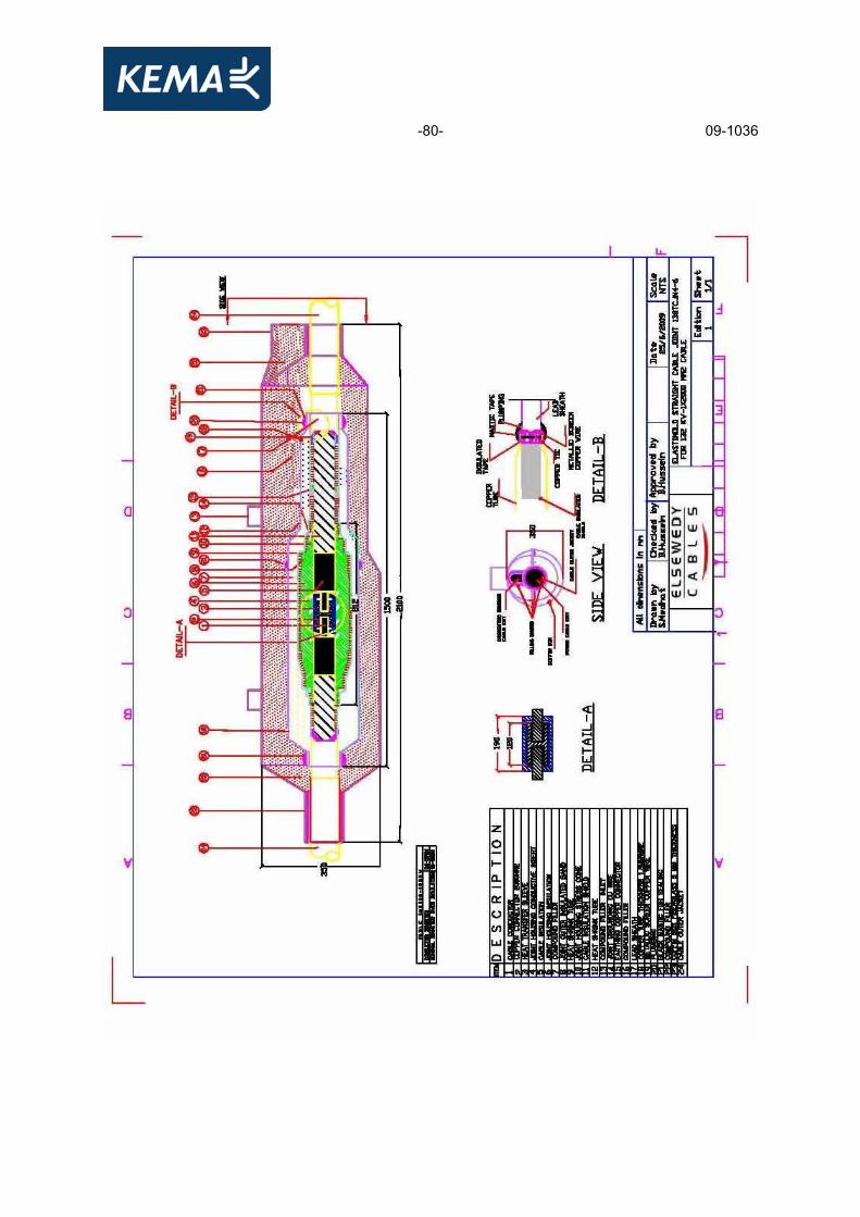
Manufacturer Elastimold, Hackettstown, New Jersey, USA Type 138TCJ1N4-6 Year of manufacture 2009 Rated voltage, U0/U (Um) 76/132 (145) kV Copper connector type crimp connector Inner diameter copper connector 58 mm Outer diameter copper connector 77,5 mm Aluminium heat sink covers length 190 mm Al. heat sink opening diameter conductor 56 mm Al. heat sink inner diameter 81 mm Al. heat sink outer diameter 90 mm Serial no stress cone 11083 Joint housing overall length 812,8 mm Joint housing inner diameter 72,39 mm Joint housing overall outer diameter 198,58 mm Compound filler two component massive filler Length of copper tube 1500 mm 1.1.5 Cross-bonding joint
Manufacturer Elastimold, Hackettstown, New Jersey, USA Type 138TCJ1S4-6 Year of manufacture 2009 Rated voltage, U0/U (Um) 76/132 (145) kV Copper connector type crimp connector Inner diameter copper connector 58 mm Outer diameter copper connector 77,5 mm Aluminium heat sink covers length 190 mm Al. heat sink opening diameter conductor 56 mm Al. heat sink inner diameter 81 mm Al. heat sink outer diameter 90 mm Serial no stress cone 0509496 Joint housing overall length 812,8 mm Joint housing inner diameter 72,39 mm Joint housing overall outer diameter 198,58 mm Compound filler two component massive filler Length of copper tube 1500 mm Length of copper tube insulating ring 150 mm Bonding cable type Manufacturer Elsewedy Cables

-8- 09-1036
Type Concentric cable Rated voltage, U0/U (Um) 1,9 / 3,3 (3,6) kV Marking on the cable
ELSEWEDY CABLES ELECTRIC CABLE
1X300 MM2 CU/XLPE/CW/PVC Conductor - material soft drawn copper - nominal cross-sectional area 300 mm2 - nominal diameter 20,6 mm approx. - type stranded circular compacted - maximum conductor temperature
in normal operation 90 °C
Conductor screen n.a. Insulation - material XLPE - nominal thickness (tn) 2,5 mm - nominal inner diameter of insulation (dii) 20,6 mm - nominal outer diameter of insulation (Dio) 25,6 mm - material designation LE4423-4476 LD - manufacturer Borealis Insulation screen n.a. Metallic armour - material soft drawn copper - number and nominal diameter of wires 74 wires of Ø 2,26 mm - nominal thickness and width of tape 0,1 x 20 mm (open helix) - cross-sectional area 300 mm2 Oversheath - material PVC, type ST2 - nominal thickness 3 mm - nominal overall diameter of the cable 41,5 mm approx. - material designation extruded - manufacturer SED Plaste - colour black - graphite coating applied yes
-9- 09-1036
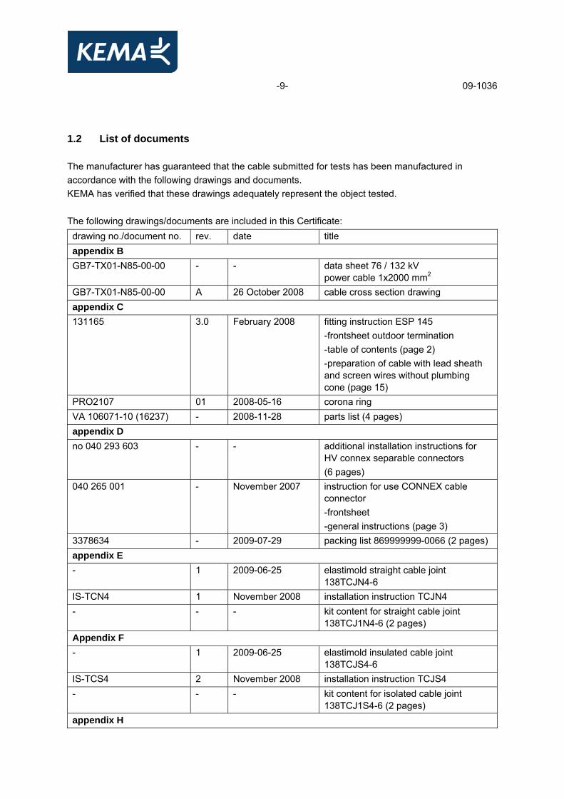
1.2 List of documents The manufacturer has guaranteed that the cable submitted for tests has been manufactured in accordance with the following drawings and documents. KEMA has verified that these drawings adequately represent the object tested.
The following drawings/documents are included in this Certificate: drawing no./document no. rev. date title appendix B GB7-TX01-N85-00-00 - - data sheet 76 / 132 kV
power cable 1x2000 mm2 GB7-TX01-N85-00-00 A 26 October 2008 cable cross section drawing appendix C 131165 3.0 February 2008 fitting instruction ESP 145
-frontsheet outdoor termination -table of contents (page 2) -preparation of cable with lead sheath and screen wires without plumbing cone (page 15)
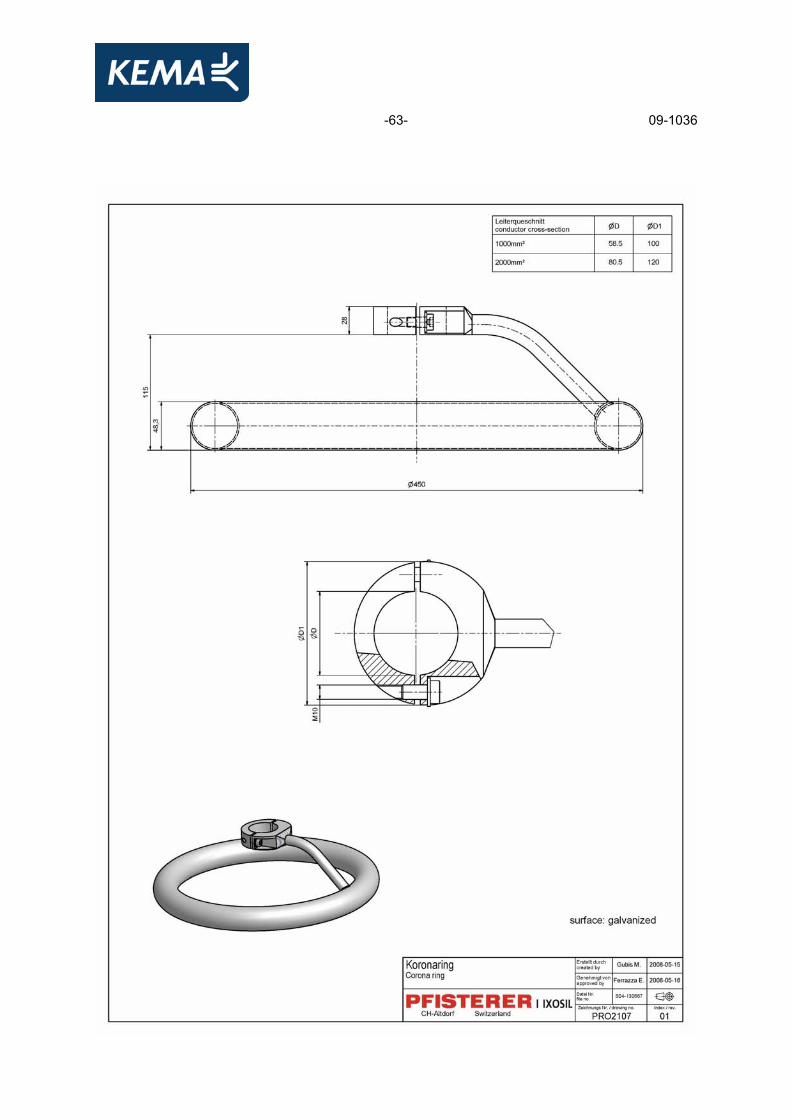
PRO2107 01 2008-05-16 corona ring VA 106071-10 (16237) - 2008-11-28 parts list (4 pages) appendix D no 040 293 603 - - additional installation instructions for
HV connex separable connectors (6 pages)
040 265 001 - November 2007 instruction for use CONNEX cable connector -frontsheet -general instructions (page 3)
3378634 - 2009-07-29 packing list 869999999-0066 (2 pages) appendix E - 1 2009-06-25 elastimold straight cable joint
138TCJN4-6 IS-TCN4 1 November 2008 installation instruction TCJN4 - - - kit content for straight cable joint
138TCJ1N4-6 (2 pages) Appendix F - 1 2009-06-25 elastimold insulated cable joint
138TCJS4-6 IS-TCS4 2 November 2008 installation instruction TCJS4 - - - kit content for isolated cable joint
138TCJ1S4-6 (2 pages) appendix H

-10- 09-1036
- 1 2009-06-25 elastimold insulated cable joint 138TCJS4-6
The following drawings/documents are only listed for reference and are kept in KEMA's files:
drawing no./document no. rev. date title
131165 3.0 - fitting instruction ESP 145 040 265 001 - November 2007 instruction for use CONNEX cable
connector - - - parts list HV-SF6 test joint size
6 – 170 kV (2 pages) - - - HV-connex Joint operating instructions
SD-138N4 B 12-8-05 138TCJN4 Stress cone SD-138S4 C 12-8-05 138TCJS4 Stress cone
11115001012090 3 2008-02-30 copper tube for straight joint 11115001011025 1 2009-06-07 coffin box for straight & isolated joint
11102003012360 1 2009-02-17 aluminium heat sink 2000 11102002042180 8 2009-08-02 copper connector 2000
11115001012110 1 2009-06-07 copper tube for isolated joint 11115001011026 2 2009-06-13 coffin box for straight & isolated joint
-11- 09-1036
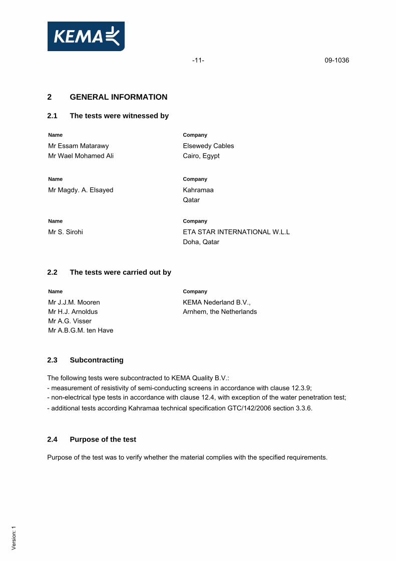
2 GENERAL INFORMATION 2.1 The tests were witnessed by Name Company
Mr Essam Matarawy Elsewedy Cables Mr Wael Mohamed Ali Cairo, Egypt
Name Company
Mr Magdy. A. Elsayed Kahramaa Qatar Name Company
Mr S. Sirohi ETA STAR INTERNATIONAL W.L.L Doha, Qatar 2.2 The tests were carried out by Name Company
Mr J.J.M. Mooren KEMA Nederland B.V., Mr H.J. Arnoldus Arnhem, the Netherlands Mr A.G. Visser Mr A.B.G.M. ten Have 2.3 Subcontracting The following tests were subcontracted to KEMA Quality B.V.: - measurement of resistivity of semi-conducting screens in accordance with clause 12.3.9; - non-electrical type tests in accordance with clause 12.4, with exception of the water penetration test; - additional tests according Kahramaa technical specification GTC/142/2006 section 3.3.6. 2.4 Purpose of the test Purpose of the test was to verify whether the material complies with the specified requirements.
Ver
sion
: 1

-12- 09-1036
2.5 Measurement uncertainty A table with measurement uncertainties is enclosed in appendix A. unless otherwise indicated in the report, the measurement uncertainties of the results presented are as indicated in this table. 2.6 Applicable standards When reference is made to a standard and the date of issue is not stated, this applies to the latest issue, including amendments, which have been officially published prior to the date of the tests.
Ver
sion
: 1

-13- 09-1036
3 ELECTRICAL TYPE TESTS 3.1 General 3.1.1 Tests at elevated conductor temperature For the tests with the cable system at elevated temperature, a reference loop for temperature control of the conductor was installed. The reference cable was cut from the total cable length submitted by the client intended for the type test. This reference loop was installed close to the main loop in order to create the same environmental conditions as for the test loop. The heating currents in both the reference loop and the test loop were kept equal at all times, thus the conductor temperature of the reference loop is representative for the conductor temperature of the test loop. Annex A, method 1 of IEC 60840 was used as a guide. The tests at elevated temperature are carried out two hours after thermal equilibrium has been established.
Ver
sion
: 1

-14- 09-1036
3.2 Test voltage values
Standard and date Standard IEC 60840, clause 12.3.1 Test date 27 April 2009
nominal thickness (mm)
maximum allowed thickness (mm)
measured average thickness (mm)
15,0 15,0 + 5% = 15,75 15,41 Result The average thickness of the insulation did not exceed the nominal value by more than 5%. The test voltages shall be the normal values specified for the rated voltage of the cable.
Ver
sion
: 1

-15- 09-1036
3.3 Bending test followed by a partial discharge test 3.3.1 Bending test
Standard and date Standard IEC 60840, clause 12.3.3 Test date 14 April 2009
Environmental conditions Ambient temperature 18 °C Temperature of test object 18 °C Characteristic test data Bending diameter: “Cable with lead, corrugated metallic sheath or metal foil”
25(d + D) + 5%
measured outer diameter of cable D (mm)
measured diameter of cable conductor d (mm)
maximum required bending diameter Dr
(mm)
diameter of test cylinder Dt
(mm) 118,1 56,1 Dr ≤ 4573 4300
Procedure The test sample shall be bent around a test cylinder at ambient temperature for at least one complete turn. It shall then be unwound and repeated, except that the bending of the sample shall be in the reverse direction without axial rotation. This cycle of operation shall be carried out three times. Observation The test was carried out successfully.
Ver
sion
: 1

-16- 09-1036
3.3.2 Partial discharge test
Standard and date Standard IEC 60840, clause 12.3.4 Test date 22 June 2009
Environmental conditions Ambient temperature 20 °C Temperature of test object 20 °C Characteristic test data Circuit balanced Calibration 5 pC Noise 2 pC Sensitivity 4 pC Required sensitivity ≤ 5 pC Bandwidth 40-400 kHz Test frequency 50 Hz Coupling capacitor 2600 pF
core voltage applied, 50 Hz duration partial discharge level
xU0 (kV) (s) (pC)
1 1,75 133 10 1,5 114 - not detectable
Requirement There shall be no detectable discharge exceeding the declared sensitivity from the test object at 1,5xU0. Result The test was passed.
Ver
sion
: 1

-17- 09-1036
3.4 Tan δ measurement
Standard and date Standard IEC 60840, clause 12.3.5 Test date 25 June 2009
Environmental conditions Ambient temperature 20 °C Temperature of test object 97 °C Characteristic test data Length of test cable 20,9 m Length of accessories 10,55 m Standard capacitor 100 pF
core voltage applied, 50 Hz core capacitance 1) tan δ xU0 (kV) (μF/km)
1 1 76 0,262 5,8x10⁻⁴ 1) for information only
Note The measured core capacitance and tan δ is measured on the complete cable system consisting of two outdoor terminations, two SF6 terminations, back to back, one straight joint and one cross-bonding joint. Requirement The measured value shall not be higher than 10x10-4 at U0. Result The test was passed.
Ver
sion
: 1

-18- 09-1036
3.5 Heating cycle voltage test
Standard and date Standard IEC 60840, clause 12.3.6 Test period 30 June until 20 July 2009
Environmental conditions Ambient temperature 20 °C Characteristic test data Heating method conductor current Stabilized temperature 97 °C
no. of heating- cycles
required steady conductor temperature
heating current at stable condition
heating per cycle cooling per cycle
voltage per cycle
(°C)
(A)
total duration (hours)
duration of conductor at steady temperature (hours)
total duration (hours)
total duration (hours)
applied voltage 2U0 (kV)
20 95-100 2925 8 2 16 24 152 Requirements No breakdown shall occur. Procedure The heating shall be applied for at least 8 hrs. The conductor temperature shall be maintained within the stated temperature limits for at least 2 h of each heating period. This shall be followed by at least 16 h of natural cooling in air to a conductor temperature within 10 K of the ambient temperature. Observation The test was carried out successfully.
Ver
sion
: 1

-19- 09-1036
3.6 Partial discharge tests 3.6.1 Partial discharge test at ambient temperature
Standard and date Standard IEC 60840, clause 12.3.4 Test date 21 July 2009
Environmental conditions Ambient temperature 20 °C Temperature of test object 20 °C Characteristic test data Circuit balanced Calibration 5 pC Noise 2 pC Sensitivity 4 pC Required sensitivity ≤ 5 pC Bandwidth 40-400 kHz Test frequency 50 Hz Coupling capacitor 2600 pF
core voltage applied, 50 Hz duration partial discharge level
xU0 (kV) (s) (pC)
1 1,75 133 10 - 1,5 114 - not detectable
Requirement There shall be no detectable discharge exceeding the declared sensitivity from the test object at 1,5xU0. Result The test was passed.
Ver
sion
: 1
-20- 09-1036
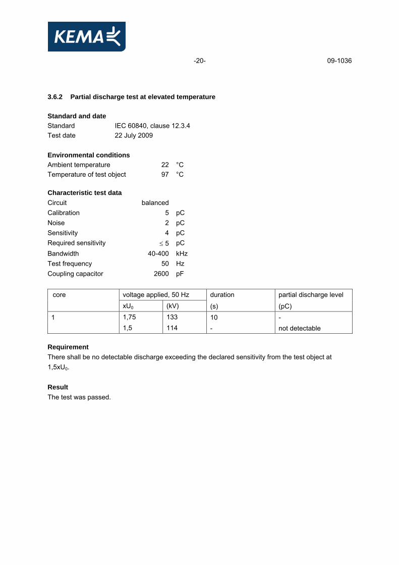
3.6.2 Partial discharge test at elevated temperature
Standard and date Standard IEC 60840, clause 12.3.4 Test date 22 July 2009
Environmental conditions Ambient temperature 22 °C Temperature of test object 97 °C Characteristic test data Circuit balanced Calibration 5 pC Noise 2 pC Sensitivity 4 pC Required sensitivity ≤ 5 pC Bandwidth 40-400 kHz Test frequency 50 Hz Coupling capacitor 2600 pF
core voltage applied, 50 Hz duration partial discharge level
xU0 (kV) (s) (pC)
1 1,75 133 10 - 1,5 114 - not detectable
Requirement There shall be no detectable discharge exceeding the declared sensitivity from the test object at 1,5xU0. Result The test was passed.

-21- 09-1036
3.7 Lightning impulse test followed by a power-frequency voltage test 3.7.1 Impulse test Standard and date Standard IEC 60840, clause 12.3.7 Test date 23 July 2009
Environmental conditions Ambient temperature 20 °C Temperature of test object 97 °C Characteristic test data Specified test voltage 650 kV The waveshape of the impulse voltage was determined at approximately 50 percent of the specified test value (see figure 1 and 5).
Requirement No breakdown of the insulation shall occur. Result The test was passed.
testing arrangement polarity voltage applied (% of test voltage)
no. of impulses see figure
voltage applied to
earthed
conductor metallic positive 50 1 1 (waveshape) screen 65 1 2 80 1 2 100 10 3 and 4 conductor metallic negative 50 1 5 (waveshape) screen 65 1 6 80 1 6 100 10 7 and 8
Ver
sion
: 1

-22- 09-1036

-23- 09-1036

-24- 09-1036
3.7.2 Power frequency voltage test
Standard and date Standard IEC 60840, clause 12.3.7 Test date 24 July 2009
Environmental conditions Ambient temperature 20 °C Temperature of test object 20 °C
testing arrangement voltage applied, 50 Hz
duration
voltage applied to earth connected to xU0 (kV) (min) conductor metallic screen 2,5 190 15
Requirement No breakdown of the insulation shall occur. Result The test was passed.
-25- 09-1036
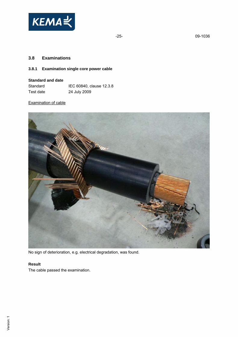
3.8 Examinations 3.8.1 Examination single core power cable
Standard and date Standard IEC 60840, clause 12.3.8 Test date 24 July 2009 Examination of cable
No sign of deterioration, e.g. electrical degradation, was found. Result The cable passed the examination.
Ver
sion
: 1

-26- 09-1036
3.8.2 Examination outdoor termination
Standard and date Standard IEC 60840, clause 12.3.8 Test date 27 till 28 August 2009 Examination outdoor termination
Result The outdoor termination passed the examination. No sign of deterioration, e.g. electrical degradation, was found.
-27- 09-1036
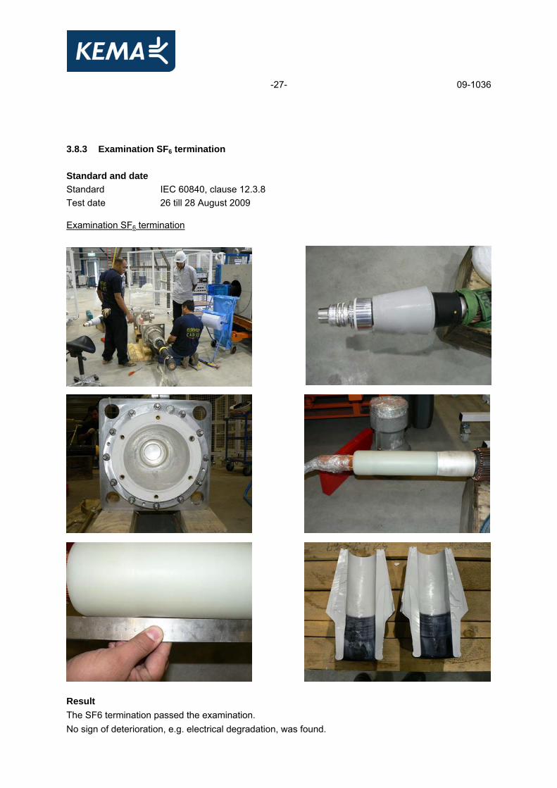
3.8.3 Examination SF6 termination
Standard and date Standard IEC 60840, clause 12.3.8 Test date 26 till 28 August 2009 Examination SF6 termination Result The SF6 termination passed the examination. No sign of deterioration, e.g. electrical degradation, was found.

-28- 09-1036
3.8.4 Examination straight joint
Standard and date Standard IEC 60840, clause 12.3.8 Test date 31 August 2009 Examination straight joint
Result The straight joint passed the examination. No sign of deterioration, e.g. electrical degradation, was found.
-29- 09-1036
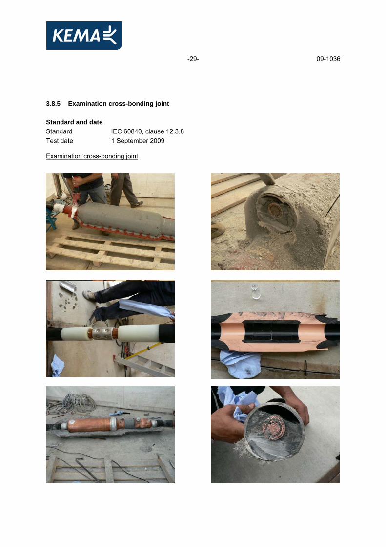
3.8.5 Examination cross-bonding joint
Standard and date Standard IEC 60840, clause 12.3.8 Test date 1 September 2009 Examination cross-bonding joint

-30- 09-1036
Result The cross-bonding joint passed the examination. No sign of deterioration, e.g. electrical degradation, was found.

-31- 09-1036
3.9 Resistivity of semi-conducting screens
Standard and date Standard IEC 60840, clause 12.3.9 Test period 16 April 2009 until 28 April 2009
Characteristic test data Temperature during ageing 100 °C Duration 7 days Resistivity measured at 90 ± 2 °C
item unit requirement measured/determined
conductor screen - without ageing Ωm ≤ 1000 53,5 - after ageing Ωm ≤ 1000 41,0 insulation screen - without ageing Ωm ≤ 500 5,1 - after ageing Ωm ≤ 500 2,2
Result The test was passed.
Ver
sion
: 1

-32- 09-1036
4 TEST OF OUTER PROTECTION FOR BURIED JOINTS The joint outer protection test was carried out in accordance with Annex H of IEC 60840. The cross-bonding joint has already passed the heating cycle voltage test (see paragraph 3.5). The results are presented below. 4.1 Water immersion and heat cycling
Standard and date Standard IEC 60840, Annex H3 Test period 13 August 2009 until 27 August 2009 Characteristic test data Cold water temperature 22 °C Hot water temperature 90 °C Water height above cable centre 1 m no. of cycles stabilizing
temperature heating per cycle cooling per cycle
(°C)
total duration (hours:min)
duration of conductor at steady temperature (hours:min)
total duration (hours:min)
20 70-75 3:20 5:20 3:20 Note The complete cross-bonding joint was mounted in a vessel with a volume of 2 m3 (length 4 meter and diameter of 0,8 meter). The manufacturer has identified the water barriers given in drawing, attached in appendix H. Procedure A total of 20 heating/cooling cycles shall be applied by raising the water temperature to within 15 °C to 20 °C below the maximum temperature of the cable conductor in normal operation In each cycle the water shall be raised to the specified temperature, maintained at the level for at least 5 hours and then be permitted to cool within 10 K above ambient temperature. Observation The test was carried out successfully.

-33- 09-1036
4.2 Voltage tests 4.2.1 DC voltage test
Standard and date Standard IEC 60840, Annex H4.2.1 Test period 27 August 2009 Atmospheric conditions Ambient temperature 20 °C Temperature of test object 28 °C testing arrangement voltage applied duration
voltage applied to earth connected to (kV) (min) bonding lead conductor bonding lead screen, vessel,
conductor main cable 20 1
bonding lead screen and bonding lead conductor
vessel, conductor main cable
20 1
Requirement No breakdown of the insulation shall occur. Result The test was passed.
Ver
sion
: 1

-34- 09-1036
4.2.2 Impulse voltage test each part to earth
Standard and date Standard IEC 60840, Annex H4.2.2.2 Test period 27 August 2009 Atmospheric conditions Ambient temperature 21 °C Temperature of test object 24 °C Characteristic test data Specified test voltage 30 kV Water height above cable centre
1 m
The waveshape of the impulse voltage was determined at approximately 50 percent of the specified test value (see figure 1 and 5).
Requirement No breakdown of the insulation shall occur. Result The test was passed.
testing arrangement polarity voltage applied (% of test voltage)
no. of impulses
see figure
voltage applied to earthed positive 50 1 1
(waveshape) 65 1 2 80 1 2
bonding lead screen and bonding lead conductor
vessel, conductor main cable
100 10 3 and 4
negative
50 1 5 (waveshape)
65 1 6 80 1 6
bonding lead screen and bonding lead conductor
vessel, conductor main cable
100 10 7 and 8
Ver
sion
: 1

-35- 09-1036

-36- 09-1036

-37- 09-1036
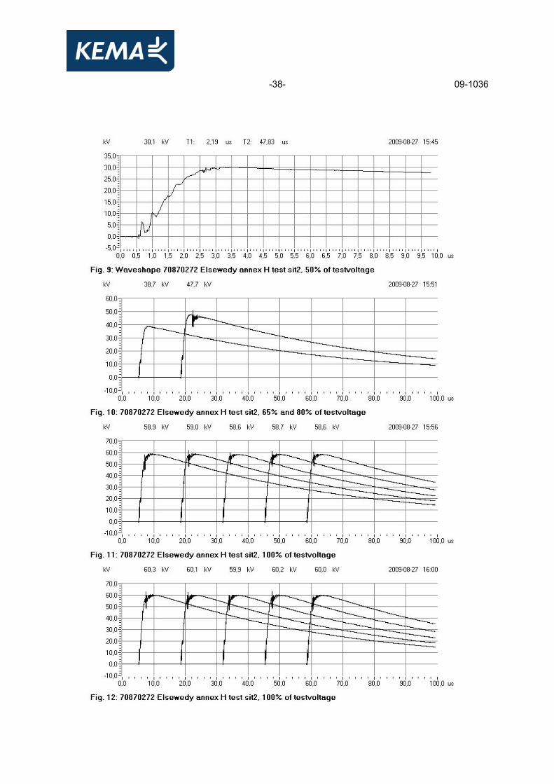
4.2.3 Impulse voltage test between parts Standard and date Standard IEC 60840, Annex H.4.2.2 Test period 27 August 2009 Atmospheric conditions Ambient temperature 21 °C Temperature of test object 22 °C Characteristic test data Specified test voltage 60 kV Assembly removed from the water
yes
The waveshape of the impulse voltage was determined at approximately 50 % of the specified test value (see figure 9 and 13).
Note The cross-bonding joint was not removed from the vessel. Requirement No breakdown of the insulation shall occur. Result The test was passed.
testing arrangement polarity voltage applied (% of test voltage)
no. of impulses
see figure
voltage applied to
earthed
positive 50 1 9 (waveshape) 65 1 10 80 1 10
bonding lead conductor
bonding lead screen, vessel, conductor main cable
100 10 11 and 12 negative 50 1 13 (waveshape) 65 1 14 80 1 14
bonding lead conductor
bonding lead screen, vessel, conductor main cable
100 10 15 and 16
-38- 09-1036

-39- 09-1036

-40- 09-1036
4.2.4 Examination cross-bonding joint
Standard and date Standard IEC 60840, annex H.5 Test date 1 September 2009 Examination cross-bonding joint (see also photographs at paragraph 3.8.5) No signs of water ingress via the identified water barriers, as outlined in the manufacturers drawing in appendix H or internal corrosion was found. Note Also there was no water found behind the coffin box. At the entrance of the bonding lead to the coffin box an air gap was detected during examination (see photographs at paragraph 3.8.5). Result The cross-bonding joint passed the examination.

-41- 09-1036
5 NON-ELECTRICAL TYPE TESTS 5.1 Check of cable construction
Standard and date Standard IEC 60840, clause 12.4.1 Test date 16 April 2009 and 14 May 2009
item unit requirement specified measured/ determined
conductor - diameter of conductor mm - 55 approx. 56,1 approx. - number of wires - - 61 per segment
+7 in centre - diameter of wires mm - - 2,9 approx. - resistance at 20°C Ω/km ≤ 0,009 ≤ 0,009 0,009 thickness of insulation - nominal mm - 15 - - average mm - - 15,4 - minimum, tmin mm ≥ 13,5 - 14,99 - maximum, tmax mm - - 15,74 - (tmax – tmin) / tmax - ≤ 0,15 - 0,05 - concentricity mm - - 0,75 thickness of lead sheath - nominal mm - 2,2 - - average mm - - 2,6 - minimum, tmin mm ≥ 1,99 - 2,33 thickness of oversheath - nominal mm - 4,5 - - average mm ≥ 4,5 - 6,7 - minimum, tmin mm ≥ 3,7 - 5,6
Result The cable construction complied with the requirements.
Ver
sion
: 1

-42- 09-1036
4.1 Check of cable construction (continued)
observed/determined
construction - conductor of copper wires 5 segments stranded (Milliken) - in centre conductor of copper seven wires
- construction 1-6-12-18-24 each segment - swellable tape - semi conducting tape 0,4mm - semi conducting conductor screen - XLPE insulation - semi conducting insulation screen - semi conducting swellable double tape 70x0,4mm approx.
overlap 14 mm - copper tape 19,5 x 0,1mm open helix - screen of copper wires 50 x Ø 1,9mm approx. - semi conducting swellable double tape 70x0,4mm approx. - leadsheath - bituminized material - oversheath of HDPE
markings 132000 V ELECTRIC CABLE ELSEWEDY CABLES 1X2000MM2 2009 PROPERTY OF KAHRAMAA
outer diameter of the cable average (mm)
118,1
outer diameter of the core average (mm)
92,6
Ver
sion
: 1

-43- 09-1036
5.2 Tests for determining the mechanical properties of the insulation before and after ageing
Standard and date Standard IEC 60840, clause 12.4.2 Test period 17 April 2009 until 28 April 2009
Characteristic test data Temperature during aging 135 ± 3 °C Ageing duration 7 days
item unit requirement measured/determined
without ageing - tensile strength N/mm² ≥ 12,5 27,9 - elongation % ≥ 200 512 after ageing - tensile strength N/mm² - 28,3 - variation with samples without ageing % ± 25 max. 1 - elongation % - 547 - variation with samples without ageing % ± 25 max. 7
Result The test was passed.

-44- 09-1036
5.3 Tests for determining the mechanical properties of oversheaths before and after ageing
Standard and date Standard IEC 60840, clause 12.4.3 Test period 17 April 2009 until 28 April 2009
Characteristic test data Temperature during aging 110 ± 2 °C Ageing duration 10 days
item unit requirement measured/determined
without ageing - tensile strength N/mm² ≥ 12,5 36,4 - elongation % ≥ 300 795 after ageing - tensile strength N/mm² - 33,2 - variation with samples without ageing % - -9 - elongation % ≥ 300 781 - variation with samples without ageing % - -2
Result The test was passed.

-45- 09-1036
5.4 Ageing tests on pieces of complete cable to check compatibility of materials
Standard and date Standard IEC 60840, clause 12.4.4 Test period 17 April 2009 until April 27 2009
Characteristic test data Temperature during aging 100 ± 2 °C Ageing duration 7 days Insulation
item unit requirement measured/determined
- tensile strength N/mm² - 27,4 - variation with samples without ageing % ± 25 max. -2 - elongation % - 532 - variation with samples without ageing % ± 25 max. 4
Oversheath
item unit requirement measured/determined
- tensile strength N/mm² - 32,7 - variation with samples without ageing % - -10 - elongation % - 802 - variation with samples without ageing % - 1
Result The test was passed.

-46- 09-1036
5.5 Pressure test at high temperature on oversheath ST7
Standard and date Standard IEC 60840, clause 12.4.6 Test date 27 April 2009
Characteristic test data Temperature 110 ± 2 °C Load 27,5 N Duration 6 h
item unit requirement measured/determined
- depth of indentation % ≤ 50 1 Result The test was passed. 5.6 Hot set test for insulation XLPE
Standard and date Standard IEC 60840, clause 12.4.10 Test date 22 April 2009
Characteristic test data Air temperature 200 ± 3 °C Time under load 15 min Mechanical stress 20 N/cm2
item unit requirement measured/determined
- elongation under load % ≤ 175 65 - permanent elongation % ≤ 15 5
Result The test was passed.
-47- 09-1036
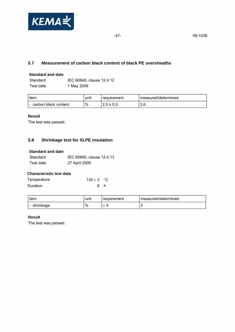
5.7 Measurement of carbon black content of black PE oversheaths
Standard and date Standard IEC 60840, clause 12.4.12 Test date 7 May 2009
item unit requirement measured/determined
- carbon black content % 2,5 ± 0,5 2,6 Result The test was passed. 5.8 Shrinkage test for XLPE insulation
Standard and date Standard IEC 60840, clause 12.4.13 Test date 27 April 2009
Characteristic test data Temperature 130 ± 3 °C Duration 6 h
item unit requirement measured/determined
- shrinkage % ≤ 4 2 Result The test was passed.

-48- 09-1036
5.9 Shrinkage test for PE oversheaths
Standard and date Standard IEC 60840, clause 12.4.14 Test date 21 April 2009 until 27 April 2009
Characteristic test data Temperature 80 ± 2 °C Duration 5 h Heating cycles 5
item unit requirement measured/determined
- shrinkage % ≤ 3 1 Result The test was passed.
Ver
sion
: 1
Ver
sion
: 1

-49- 09-1036
5.10 Water penetration test
Standard and date Standard IEC 60840, clause 12.4.18 and Annex F Test period 13 – 27 July 2009
Environmental conditions Ambient temperature 20 °C
Characteristic test data Length of cable sample 6 m Water height above cable centre 1 m Heating method conductor current Stabilized conductor temperature 96 °C
no. of heating cycles
required steady conductor temperature
heating current at stable condition
heating per cycle cooling per cycle
(°C)
(A)
total duration (hours)
duration of conductor at steady temperature (hours)
total duration (hours)
10 95-100 2800 8 2 16 Note The manufacturer has claimed that barriers have been included, which prevents longitudinal water penetration in the region of the metallic layers and along the conductor. Requirement No water shall emerge from the ends of the cable sample. Result The test was passed.
Ver
sion
: 1

-50- 09-1036
6 ADDITIONAL TEST ACCORDING KAHRAMAA SPECIFICATION 6.1 Measurement of insulation concentricity
Client specification and date Specification GTC/142/2006 section 3.3.6 clause 1.4.3.8.4 Test period 16 April 2009
item unit requirement measured/determined
thickness of insulation - average, tave mm - 15,4 - minimum, tmin mm - 14,99 - maximum, tmax mm - 15,74 - (tmax – tmin) / tave - ≤ 0,10 0,05 - concentricity maximum allowable deviation 8% of the minimum thickness
mm < 1,20 0,75
Result The test was passed. 6.2 Measurement of insulation purity
Client specification and date Specification GTC/142/2006 section 3.3.6 clause 1.4.3.8.5 Test period 19 May 2009 until 1 July 2009 item unit requirement measured
-void in insulation -any contaminant -any translucent
mm mm mm
≤ 0,05 ≤ 0,15 ≤ 0,6
0 0 0,05
Result The test was passed.
Ver
sion
: 1

-51- 09-1036
6.3 Measurement of insulation & screen moisture content
Client specification and date Specification GTC/142/2006 section 3.3.6 clause 1.4.3.8.6 Test period 19 May 2009 until July 2009
item unit requirement measured
moisture content in extruded insulation
ppm
≤ 150
12, 7, 11
item unit requirement measured
moisture content in extruded conductor screen
ppm
≤ 500
0, 0, 0
item unit requirement measured
moisture content in extruded insulation screen
ppm
≤ 500
15, 23, 18
Result The test was passed.

-52- 09-1036
6.4 Measurement of semi-conducting screen protrusions
Client specification and date Specification GTC/142/2006 section 3.3.6 clause 1.4.3.8.10 Test period 19 May 2009 until 1 July 2009
item unit requirement measured -protrusions and irregularities between the conductor screen and insulation -protrusions and irregularities between the insulation screen and insulation -outer screen examination
mm mm -
≤ 0,03 ≤ 0,03 no screen defects
0 0 no screen defects
Result The test was passed.

-53- 09-1036
6.5 Impact test on metallic sheath
Client specification and date Specification GTC/142/2006 section 3.3.6 clause 1.4.2.3.m Test period 23 July 2009 Characteristic test data Temperature 20 °C Impact weight 5 kg Dropping height 1 m Dropping angle 90 degree Length of test sample 1 m Quantity of impacts at different points
5
item unit requirement measured/determined
- oversheath examination - no cracks after test no cracks after test Result The test was passed.

-54- 09-1036
APPENDIX A MEASUREMENT UNCERTAINTIES The measurement uncertainties in the results presented are as specified below unless otherwise indicated.
measurement measurement uncertainty dielectric tests and impulse current tests
peak value: ≤ 3% time parameters: ≤ 10%
capacitance measurement tan δ measurement
0,3% ± 0,5% ± 5x10⁻⁵
partial discharge measurement < 10 pC : 2 pC 10 - 100 pC : 5 pC > 100 pC : 20%
measurement of impedance ac-resistance measurement
≤ 1%
measurement of losses ≤ 1% measurement of insulation resistance ≤ 10%
measurement of dc resistance 1 μΩ - 5 μΩ : 1% 5 μΩ - 10 μΩ : 0,5% 10 μΩ - 200 μΩ : 0,2%
radio interference test 2 dB calibration of current transformers 2,2 x 10⁻⁴ Ii/Iu and 290 μrad
calibration of voltage transformers 1,6 x 10⁻⁴ Ui/Uu en 510 μrad measurement of conductivity 5%
measurement of temperature -50 °C - -40 °C : 3 K -40 °C - 125 °C : 2 K 125 °C - 150 °C : 3 K
tensile test 1%
sound level measurement type 1 meter as per IEC 651 and ANSI S1.4.1971
measurement of voltage ratio 0,1%
Ver
sion
: 1

-55- 09-1036
APPENDIX B MANUFACTURER’S DRAWING/DATA SHEET SINGLE CORE CABLE 4 pages (including this page)
drawing no./document no. revision date title
GB7-TX01-N85-00-00 - - data sheet 76 / 132 kV power cable 1x2000 mm2
GB7-TX01-N85-00-00 A 26 October 2008 cable cross section drawing
Ver
sion
: 1

-56- 09-1036
Ver
sion
: 1

-57- 09-1036

-58- 09-1036

-59- 09-1036
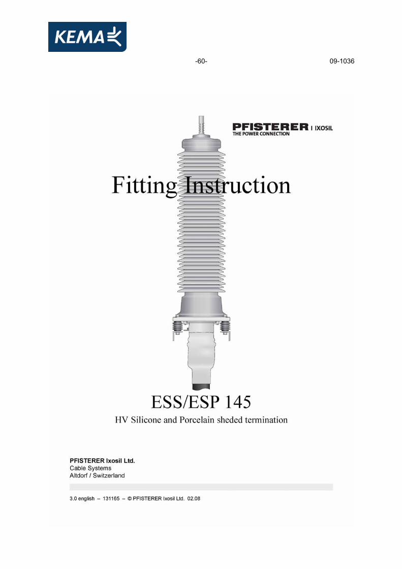
APPENDIX C MANUFACTURER’S DRAWING/DATA SHEET OUTDOOR TERMINATION 9 pages (including this page)
drawing no./document no. revision date title
131165 3.0 February 2008 fitting instruction ESP 145 -frontsheet outdoor termination -table of contents (page 2) -preparation of cable with lead sheath and screen wires without plumbing cone (page 15)
PRO2107 01 2008-05-16 corona ring
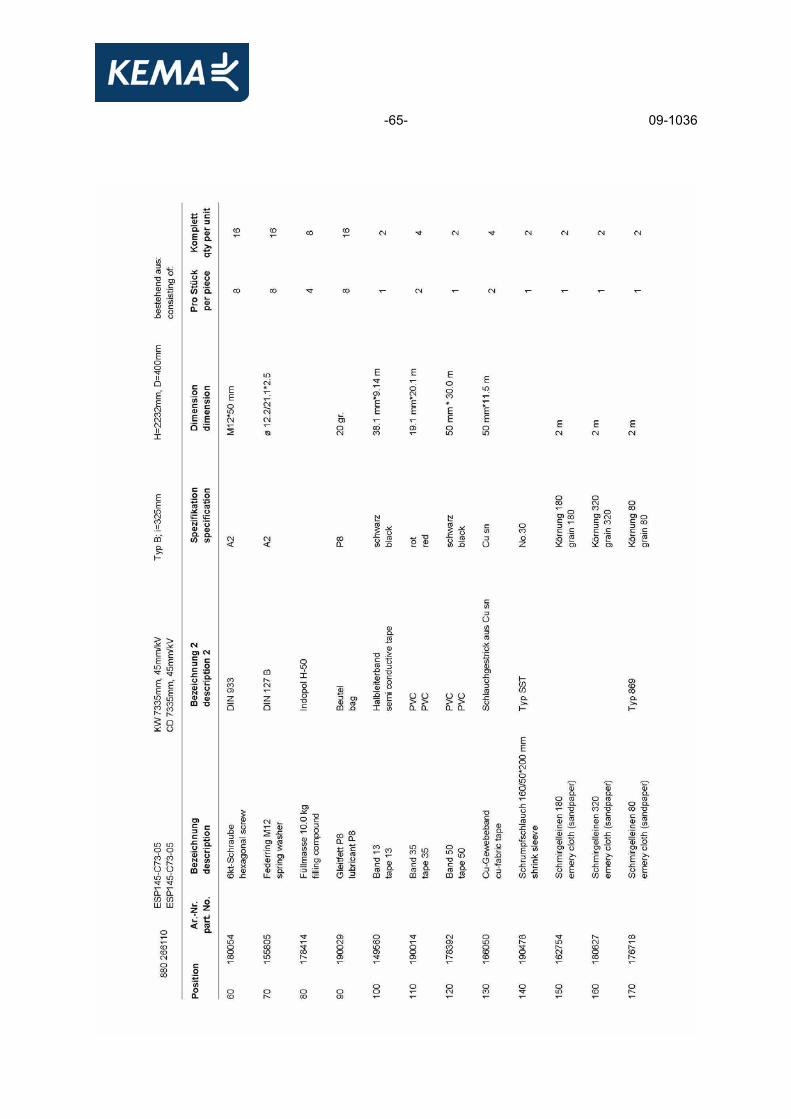
VA 106071-10 (16237) - 2008-11-28 parts list (4 pages)
-60- 09-1036

-61- 09-1036

-62- 09-1036
-63- 09-1036

-64- 09-1036
-65- 09-1036

-66- 09-1036

-67- 09-1036

-68- 09-1036
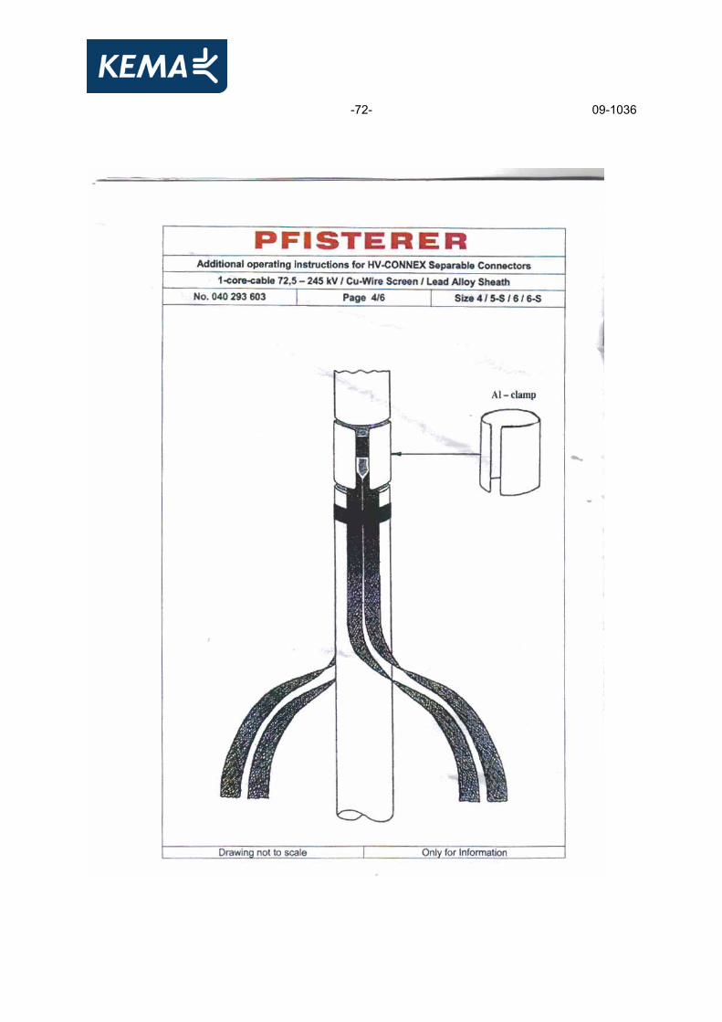
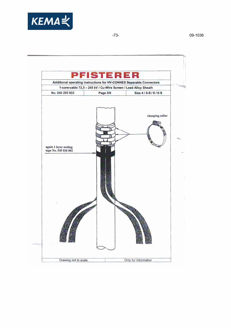
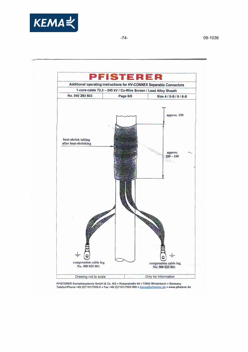
APPENDIX D MANUFACTURER’S DRAWING/DATA SHEET SF6 TERMINATION 11 pages (including this page)
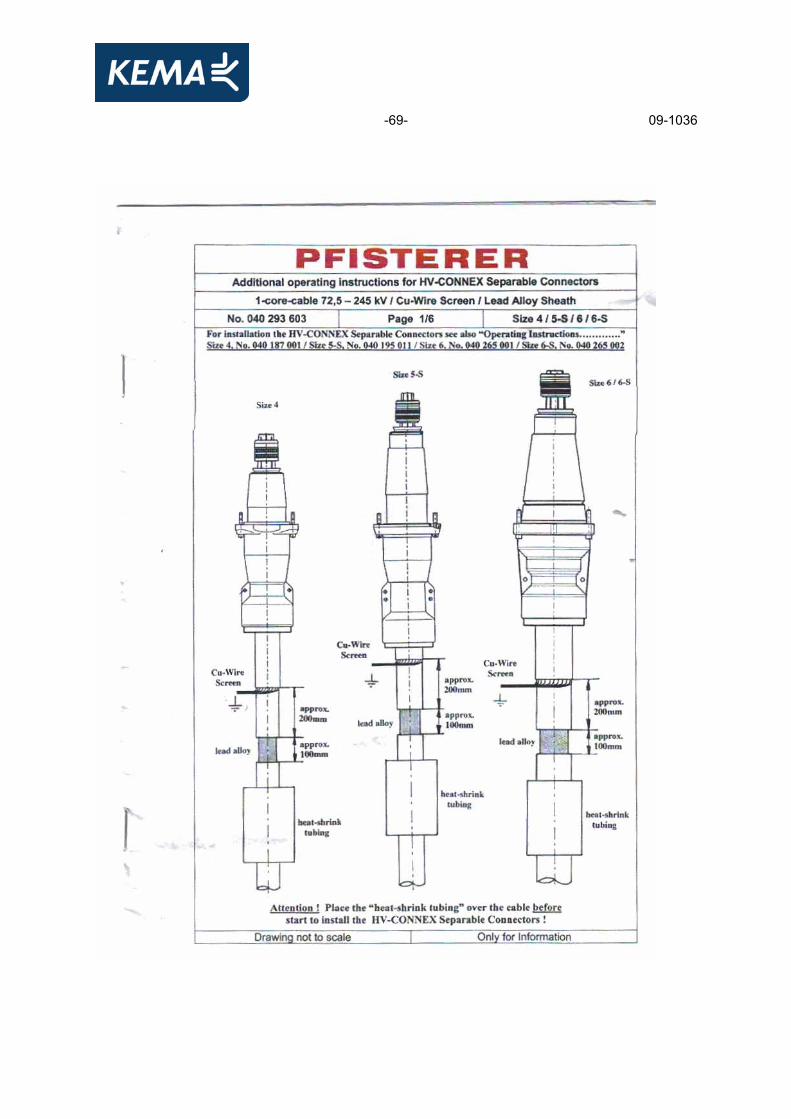
drawing no./document no. revision date title No 040 293 603 - - additional installation instructions for
HV connex separable connectors (6 pages)
040 265 001 - November 2007 instruction for use CONNEX cable connector -frontsheet -general instructions (page 3)
3378634 - 2009-07-29 packing list 869999999-0066 (2 pages)
-69- 09-1036

-70- 09-1036

-71- 09-1036
-72- 09-1036
-73- 09-1036
-74- 09-1036

-75- 09-1036

-76- 09-1036

-77- 09-1036

-78- 09-1036
-79- 09-1036
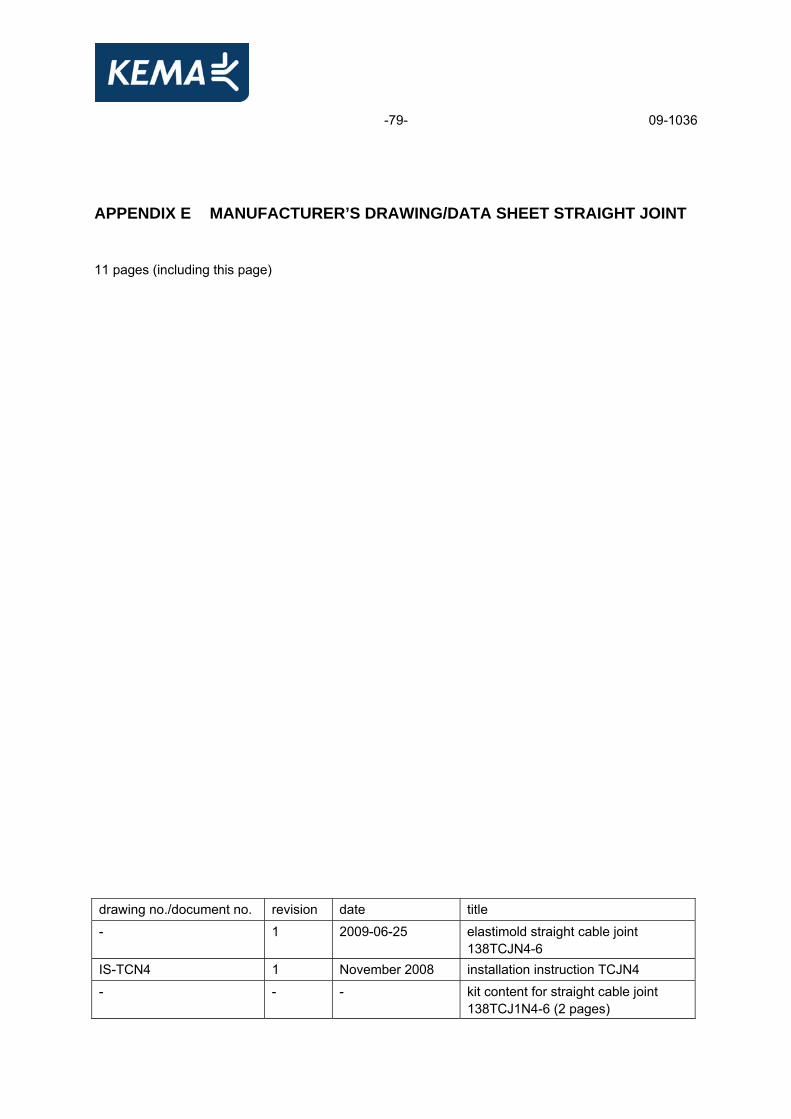
APPENDIX E MANUFACTURER’S DRAWING/DATA SHEET STRAIGHT JOINT 11 pages (including this page)
drawing no./document no. revision date title
- 1 2009-06-25 elastimold straight cable joint 138TCJN4-6
IS-TCN4 1 November 2008 installation instruction TCJN4 - - - kit content for straight cable joint
138TCJ1N4-6 (2 pages)
-80- 09-1036

-81- 09-1036

-82- 09-1036
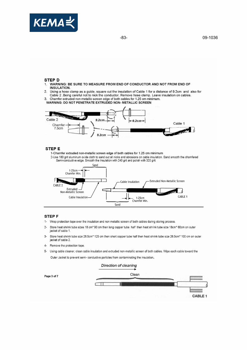
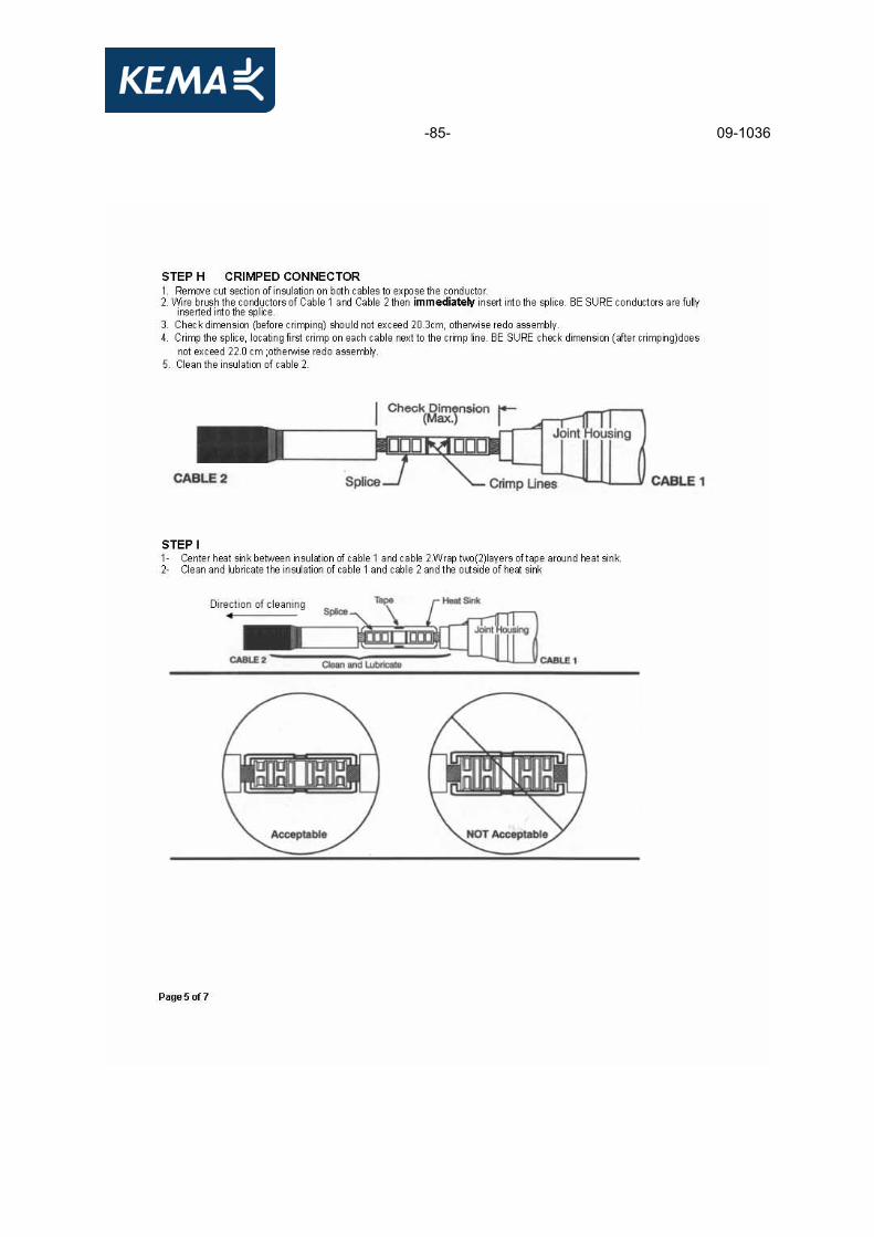
-83- 09-1036

-84- 09-1036
-85- 09-1036

-86- 09-1036

-87- 09-1036

-88- 09-1036

-89- 09-1036

-90- 09-1036
APPENDIX F MANUFACTURER’S DRAWING/DATA SHEET CROSS-BONDING JOINT 12 pages (including this page)
drawing no./document no. revision date title - 1 2009-06-25 elastimold insulated cable joint
138TCJS4-6 IS-TCS4 2 November 2008 installation instruction TCJS4
- - - kit content for isolated cable joint 138TCJ1S4-6 (2 pages)

-91- 09-1036

-92- 09-1036

-93- 09-1036

-94- 09-1036

-95- 09-1036

-96- 09-1036

-97- 09-1036

-98- 09-1036

-99- 09-1036

-100- 09-1036
-101- 09-1036

-102- 09-1036
APPENDIX G PHOTOGRAPH OF THE TEST OBJECT

-103- 09-1036
APPENDIX H WATERBARRIER ANNEX H TEST