08 - economic feasibility of hts dc cables on board a ship
TRANSCRIPT

Feasibility of HTS DC Cables
on Board a Ship
K. Allweins, E. MarzahnNexans Deutschland GmbH
10th EPRI Superconductivity Conference

Feasibility of HTS DC Cables
on Board a Ship
1. Can superconducting cables be used for
DC distribution systems on board a ship?
2. Offers this solution any operational advantages
over conventional resistive conductors?

Can superconducting cables be
used for DC distribution systems
on board a ship?

1st Generation
Bi2223 tapes
• Powder in tube process, HTS filaments are embedded in a silver matrix
• These materials can be cooled by liquid nitrogen (77 K), sub-cooled
liquid
nitrogen (65 K) or helium gas (10 - 80 K)
Typical data ………………………………………………………...
• Dimensions: 4 × 0.25 mm
• Available Length: up to 1 km
• Maximum Current: 160 - 200 A @ 77 K; sf
• Critical Temp.: 110 K (-163 °C)
• Price: ~25 $/m
Superconducting Materials

2nd Generation
YBCO coated conductor
• Superconductor material is deposited on a Ni-alloy
• YBCO can be cooled by liquid nitrogen (77 K), sub-cooled liquid nitrogen
(65 K) or helium gas (10-80 K)
Typical data ………………………………………………………...
• Dimensions: 4 × 0.1 - 0.45 mm
• Available Length: up to 1 km
• Maximum Current: 100 A @ 77 K; sf
• Critical Temp.: 92 K (-181 °C)
• Price: ~33 $/m
Superconducting Materials

2nd Generation
MgB2 wires
• Powder in tube process
• Performance/cost ratio makes it attractive for high current DC cables
• Needs to be cooled down to 20 - 30 K (helium gas)
Typical data ………………………………………………………...
• Dimensions: 1 mm²
• Available Length: up to 5 km
• Maximum Current: 1000 A at 20 K; sf
• Critical Temp. 39 K (-234 °C)
• Price: 2-4 $/m
Superconducting Materials

General design of a HTS cable
1. A former on which the HTS tapes or wires are stranded
around
2. For electrical insulation a dielectric is lapped around the
HTS materials
3. A second HTS layer on the dielectric acts as a shield or
current return
Cable Designs

Several cable principles can be used to distribute power
on board a ship:
1. One phase cable
2. Bipolar coaxial cable
3. Twisted cable
Cable Designs
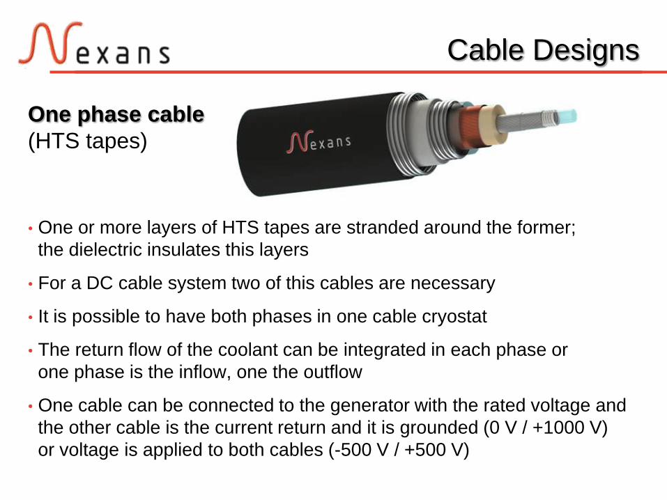
One phase cable
(HTS tapes)
• One or more layers of HTS tapes are stranded around the former;
the dielectric insulates this layers
• For a DC cable system two of this cables are necessary
• It is possible to have both phases in one cable cryostat
• The return flow of the coolant can be integrated in each phase or
one phase is the inflow, one the outflow
• One cable can be connected to the generator with the rated voltage and
the other cable is the current return and it is grounded (0 V / +1000 V)
or voltage is applied to both cables (-500 V / +500 V)
Cable Designs

Bipolar coaxial
cable (HTS tapes)
• The most compact design
• The current return is in the same cable
• The current flows in one cable from the generator to the motor and back;
no additional transfer line is needed
• Magnetic fields caused by both phases are superimposed;
there is no magnetic field outside the cable
• The cable can be operated symmetrically (-500 V / +500 V)
or with the outer HTS layer grounded (0 V/1000 V)
Cable Designs

Bipolar coaxial
cable (MgB2 wire)
• The most compact design
• The current return is in the same cable
• The current flows in one cable from the generator to the motor and back;
no additional transfer line is needed
• Magnetic fields caused by both phases are superimposed;
there is no magnetic field outside the cable
• The cable can be operated symmetrically (-500 V / +500 V)
or with the outer HTS layer grounded (0 V/1000 V)
Cable Designs
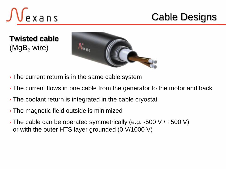
Twisted cable
(MgB2 wire)
• The current return is in the same cable system
• The current flows in one cable from the generator to the motor and back
• The coolant return is integrated in the cable cryostat
• The magnetic field outside is minimized
• The cable can be operated symmetrically (e.g. -500 V / +500 V)
or with the outer HTS layer grounded (0 V/1000 V)
Cable Designs

For operation the cable core has to be kept on its working temperature
2-wall cable cryostat (77 K):
Cryogenic Envelope
Corrugated tube Low-loss spacer
Layers of superinsulationVacuum gap
Protective PE
jacket
< Space for cable core & LN2

For operation the cable core has to be kept on its working temperature
4-wall cable cryostat (20 K):with LN2 shielding
Cryogenic Envelope
Corrugated tube Low-loss spacer
Layers of superinsulationVacuum gap
Protective PE
jacket
< Space for cable core & GHe
LN2 shield

Cable cryostat, thermal losses
• Spacers, superinsulation & vacuum secure low thermal losses
• But still a remaining heat flow
(Surface of corrugated tubes, thermal conductivity of spacers, vacuum
quality, temperature difference)
• Different designs are possible
(Specification of cable system, available space, price of cable cryostat)
• If higher thermal losses are tolerable
Compact cable cryostat, but more powerful cooling system needed
• Typical 1 W/m,
Possibility to reduce to 0.3 W/m
Cryogenic Envelope

Typical weight and the overall dimension
for a 5 kA superconducting system
Copper: ~20 kg/kA/m 10 tons for 5 kA 100 m Copper system
Cable Designs
100 m MgB 2 coaxial cable with 5 kA @ 25 K
Diameter of cable core 14.5 mm
Dimensions of cryostat din 30 mm, dout 58 mm
Weight of cable 35 + 130 kg
Volume of coolant 40 liter (He @ 25 bar)
Initial cool down time < 2 days
Cable + cryostat losses ~50 W at 25 K
55 mm
=

Terminations (overview)
• The termination represents the connection of the cable end to the
electrical devices
• An external cooling system is connected to the termination or a cooling
system can be integrated in one termination
• Its design minimize the heat load on the cryogenic machine
• Its dimensions can be adapted to application and room available for an
installation on board a ship
• For our cable system two bipolar terminations are required
(bipolar = two current leads in a cryostat)
Terminations

Current Leads
• Current leads generate most of the thermal and electrical losses
• Current leads should insure the following main specifications:
- Carry the current specified for the system without important Joule
losses
to avoid heat losses to the cryogenic media
- Limit the heat flux from ambient temperature (connection to motor /
generator) to cryogenic temperature
- Insure that cold flux from the part connected to the cryogenic area will
not create a too low temperature (can create ice at the extremity
connected to the motor / generator)
Terminations

Sketch of termination design (20 K)
Terminations
Upper metal leadsLower
HTS
leads
Superconducting cable
300-350 K65-77 K20-30 K
+V
- V

Schematic of the cooling system
• Cooling system is required to cool down the superconductor
Cooling System
Termination Cable Termination Cooling system
Re
+ - + -
Removes the heat
Provide the pressure
Circulates the coolant

Cooling system
(Liquid Nitrogen)
• For Bi2223/YBCO, the temperature is below 100 K and can
be achieved using liquid nitrogen at 65 - 77 K
• Liquid nitrogen is low price easy available and
ideal for a fast cool down of a HTS cable system
(high thermal capacitance)
Cooling System
Cooling system
(Helium gas)
• Coolant for MgB2: Helium gas
• Helium allows a wider range of temperatures down to 20 - 30 K
• The operation at a lower temperature increases the ampacity
• When a lower operating temperature is used, the cryogenic system
needs a higher cooling power
Cooling System

Volume of the coolant in cable: ~0.4 l/m
(depending on the rated current and the voltage level)
Total coolant volume:
100 m cable: 40 liter
+ Termination: ~100 liter
= 140 liter
Cooling System

Pressure drop / Temperature gradientfor three different cable designs, 100 m cable length
Cooling System
Design Mass Flow dT dP
Coaxial, He @20 K 7.9 g/ s 1.07 K 2.34 bar
Twisted, He @20 K 8.5 g/ s 0.99 K 2.06 bar
Coaxial, N2 @65 K 34.8 g/ s 0.77 K 1.56 bar

Promising cooling
solution @ 65 K
Cooling System

Promising cooling
solution @ 20 K
(2-stage system)
Cooling System

Summary
Interim conclusion
Can superconducting cables be used for
DC distribution systems on board a ship? Yes (of course)!
Benefits HTS
• Very compact cable
• Reduction of weight
• No thermal or electromagnetic impact on the environment
Drawback HTS
• Cooling system / low operating temperature

Offers a superconducting DC distribution
system on board a ship any operational
advantages over conventional
resistive conductors?

Power Distribution System
Overview
• Power distribution systems (AC or DC) can operate from low voltage (24
V)
to medium voltage (15 kV) with various ampacity from 50 - 5000 A.
• Main advantage of a DC system operating at low voltage:
No transformer or converter is required in the overall distribution system.
• The length of most distribution systems: 30 - 200 m
(300 m for huge cruise ships, LNG tankers, container carriers)
• Ampacity of conventional resistive cables is limited on maximum
operational temperature of 85 °C (ambient temperature of 45 °C).

Power Distribution System
• Replacement of high power cables between the generator and the bus-
bar
or between the bus-bar and the motor:
Diesel
Motor
(HTS)
Generator
(HTS)
Motor
Propelle
r
LoadD
C B
us

Power Distribution System
General assumptions for calculation of power losses and comparison of
conventional resistive and superconducting systems:
Bipolar distribution system
1 - 10 MW, <1000 V DC
DC cable current
1 - 7.5 kA Length
50 - 300 m
Ampacity of conventional
resistive cable systems
1- 3 A/mm²

Power Dissipation Sources
Power dissipation sources
• Heat leak through the cryostat
• Thermal conduction / dissipation through the current leads
• AC ripples
Total losses of the system
when the cable is energized:
WTotal = 2 · WTerm + L · (WCryo + WACRipple) L: Length of cable
• Heat leak from cryostat independent from rated current
• Termination losses are mostly dependant on rated current
• AC ripple losses are dependent on frequency of ripples,
rated current and amplitude of ripples

AC Ripple Power Dissipation
Voltage AC Ripples
WVACRipple = 2 · f · tan( ) · C · U²
f Frequency, max. 10 kHz
C Capacity of the cable per meter in, max 0.4 nF
U ½ Variation of the operating voltage
= 8% of the nominal voltage 1000 V
U = 40 V
Loss angle from the insulation material, 0.002° (Kapton)
WVACRipple < 0.3 mW/m
Neglible!

AC Ripple Power Dissipation
Current AC Ripples
The AC current amplitude is limited to 3% of the nominal DC current with a
maximum total harmonic distortion THD = 8%
WIACRipple = µ0 · f · Ic2 · f(i) / (Norris formula)
f(i) = (1-i) · ln(1- i) + (2-i) · i/2 (Shape factor, elliptical)
i = i / 2Ic ( i: full amplitude of ripple in [A])
The operating current of the superconducting cable is 70% of Ic

AC Ripple Power Dissipation
Current AC Ripple losses
for a typical harmonic spectrum
• Negligible for an operating current below 3 kA
(less than 10% of the 0.3 W/m cryostat losses)
• For higher currents the impact of the AC ripple
are considered in the thermal analysis
Cable class 1440 Hz 2880 Hz 5760 Hz 7200 Hz Total
1 kA 0.0002 0.0005 0.0011 0.0013 < 0.0035
2 kA 0.0009 0.0018 0.0036 0.0045 < 0.011
3 kA 0.0021 0.0043 0.0087 0.0109 < 0.027
4 kA 0.0036 0.0072 0.0145 0.0182 < 0.045
5 kA 0.0059 0.0118 0.0237 0.0296 < 0.071
7.5 kA 0.0128 0.0256 0.0512 0.0641 < 0.16

Power Dissipation of Components
Power dissipation of the main components
at the operating temperature
• Most of the heat is coming from the “upper part” of the current leads
High heat load on the cryogenic refrigerator
To be efficient, the superconducting cable system
should not be too short!
Temperature 1 kA 2 kA 3 kA 4 kA 5 kA 7.5 kA
Current
Leads (W)
77 - 90 K 99 192 287 384 482 739
20 - 30 K 2.3 2.7 3.3 4.1 5.2 8.7
Cable Cryo
(W/m)
65 - 70 K 0.3 0.3 0.4 0.5 0.5 0.5
20 - 30 K 0.3 0.3 0.4 0.4 0.4 0.4
AC Ripple
(W/m)
Operation
temperature 0 0 0 0.05 0.07 0.16

Power Dissipation of Components
Power efficiency of the cryogenic refrigerators*
[W at room temp. / W at operating temp.]
used for the calculations
* Values from commercial systems available today.
The efficiencies of the cooling machines are in the
range of 8 - 17% of the Carnot Cycle
Temperature Carnot cycle 30 - 200 W 200 - 500 W 500 -1000 W
65-90 K 3.45 31 28 20
30 K 7.5 96 NA NA
20 K 15 190 NA NA

Comparison of Cu & SC System
• The losses of superconducting system are compared with
losses of conventional resistive system
• Copper cables have same length, operate at same ampacity
• Current density in the copper system is 1-3 A/mm²
• Losses copper system (single phase):
Figure of merit
• Ratio losses copper system / losses superconducting system
• Superconducting system is more efficient when this ratio is above 1
23 W/kA/m 1 A/mm²
92 W/kA/m 2 A/mm²
210 W/kA/m 3 A/mm²

Comparison of Cu & SC System
T = 65 K, JCu = 2 A/mm²
0
2
4
6
8
10
12
14
0 50 100 150 200 250 300 350
Loss
es
Co
pp
er(
W) /
Loss
es
Sc (W
)
Length (m)
Comparison of SC and Cu distribution system T op = 65 K ; J cu = 2 A/mm2
1 kA
2 kA
3 kA
4 kA
5 kA
7,5 kA

Comparison of Cu & SC System
T = 30 K, JCu = 2 A/mm²
0
1
2
3
4
5
6
7
8
9
10
0 50 100 150 200 250 300 350
Loss
es
Co
pp
er(
W) /
Loss
es
Sc (W
)
Length (m)
Comparison of SC and Cu distribution system T op = 30 K ; J cu = 2 A/mm2
1 kA
2 kA
3 kA
4 kA
5 kA
7,5 kA

Comparison of Cu & SC System
T = 20 K, JCu = 2 A/mm²
0
1
2
3
4
5
6
7
0 50 100 150 200 250 300 350
Loss
es
Co
pp
er(
W) /
Loss
es
Sc (W
)
Length (m)
Comparison of SC and Cu distribution system T op = 20 K ; J cu = 2 A/mm2
1 kA
2 kA
3 kA
4 kA
5 kA
7,5 kA

Comparison of Cu & SC System
Minimum length for SC, T = 65 K
0
20
40
60
80
100
120
140
160
180
200
0 1 2 3 4 5 6 7 8
len
ght
(m)
Ampacity (kA)
Minimun length T op = 65 K
1 A/mm2
1,5 A/mm2
2 A/mm2
3 A/mm2

Comparison of Cu & SC System
Minimum length for SC, T = 30 K
0
20
40
60
80
100
120
140
160
180
200
0 1 2 3 4 5 6 7 8
len
ght
(m)
Ampacity (kA)
Minimun length T op = 30 K
1 A/mm2
1,5 A/mm2
2 A/mm2
3 A/mm2

Comparison of Cu & SC System
Minimum length for SC, T = 20 K
0
20
40
60
80
100
120
140
160
180
200
0 1 2 3 4 5 6 7 8
len
ght
(m)
Ampacity (kA)
Minimun length T op = 20 K
1 A/mm2
1,5 A/mm2
2 A/mm 2
3 A/mm2

Comparison of Cu & SC System
1. A “short” superconducting distribution system with a length of 50 m
can efficiently replace a copper system especially when the space on
board a ship is limited
2. A reduction of the losses up to a factor of 15 can be obtained with a
superconducting system
3. The efficiency of the superconducting system is increasing with the
distributed current and with the operating temperature
4. A system operating at 20 - 30 K with MgB2 can be more efficient
than a conventional copper system

Energy Saving
Overall losses in kW in a 100 m long distribution system
(losses % of the transported energy)
Sources of losses for MVDC: Transformers with 97.5% efficiency
Temp. 1 MW
(1 kA,1 kV)
2 MW
(2 kA,1 kV)
3 MW
(3 kA,1 kV)
4 MW
(4 kA,1 kV)
5 MW
(5 kA,1 kV)
7.5 MW
(7.5kA,1kV)
20 K 13
(1.3 %)
19
(0.95%)
23
(0.77%)
24
(0.6%)
30
(0.56%)
39
(0.52%)
30 K 9
(0.9 %)
15
(0.75%)
20
(0.75%)
21
(0.48%)
23
(0.46%)
33
(0.45%)
65 K 7
(0.7%)
13
(0.65%)
17
(0.57%)
18
(0.45%)
19
(0.39%)
29
(0.39%) Ref Copper
1.5 A/mm2
356 K
10
(1%)
20
(1%)
30
(1%)
40
(1%)
50
(1%)
75
(1%)
MVDC
10 kV
50
(5%)
100
(5%)
150
(5%)
200
(5%)
250
(5%)
375
(5%)

Energy Saving
1. In high current DC cables high energy can be transported at low
voltage with a very high efficiency (losses <1%)
2. Such a system does not require medium voltage trans-
formers or converters where 2 - 5% of the energy is lost
3. A 100 m long, 5 MW superconducting power distribution system in
operation during 300 days per year can save:
- 150 - 250 MWh per year in comparison with a
conventional DC system
- 1.5 GWh per year in comparison with a conventional
MVAC (AC 10 kV - 500 Arms) system
4. It contribute to recover the investments required for a superconducting
system

Conclusion
Conclusion
1. HTS cables systems can have various designs; compared to copper
cable, all designs are very compact and very light
2. Thermal and magnetic independency allows optimized installation
possibilities
3. Due to low losses of HTS cable systems these are viable for length of
more than 30 -100 m, depending on the rated current and the
operating temperature
4. Power transmission architecture on board a ship can be realized at
low voltage levels with high currents
5. Transmission architecture for classical cable (MVAC) needs
converters and transformers to reduce the losses

Outlook
Outlook
Beside the use as a power transmission cable on board a ship,
other applications are imaginable:
1. Navy ships can be equipped with HTS degaussing cables (to
neutralize the magnetic signature of the ship); a first HTS degaussing
was tested 2009 by the US Navy on the destroyer USS Higgins
2. High power DC cable systems can replace several transmission
systems at land; every application, where DC currents are required,
can be operated by a HTS cable

Thank you
for your attention!
10th EPRI Superconductivity Conference