06-packet switching on lan and stp ss2007 v4-9...datenkommunikation 384.081 - ss 2007 l06 - packet...
TRANSCRIPT

Datenkommunikation 384.081 - SS 2007
L06 - Packet Switching on LAN (TB, STP)
© 2007, D.I. Manfred Lindner
Page 06 - 1
Packet Switching on L2 (LAN Level)
Transparent Bridging (TB), Spanning Tree Protocol (STP),Rapid STP, L2 Bridging versus L3 Routing
© 2007, D.I. Manfred Lindner Packet Switching on L2, v4.9 2
Agenda
• Introduction
• Transparent Bridging Basics
• Spanning Tree Protocol
• Rapid Spanning Tree Protocol
• Comparison L3 Routing versus L2 Bridging
Datenkommunikation 384.081 - SS 2007
L06 - Packet Switching on LAN (TB, STP)
© 2007, D.I. Manfred Lindner
Page 06 - 2
© 2007, D.I. Manfred Lindner Packet Switching on L2, v4.9 3
• LAN was primarily designed for shared media– but too many clients cause problems
• higher probability for collisions
• Partitioning of a network may be needed – to achieve load balance
– for error limitation
– because of security reasons
– to deal with technological limitations• geographical expansion, number of clients
– for using resources of distant networks (remote networking)
Why Packet Switching on LAN?
© 2007, D.I. Manfred Lindner Packet Switching on L2, v4.9 4
Bridge / Router
• network partitioning– can be done by packet switches (OSI relay stations on L3)
• well known store and forward principle
• bridge– packet switch implemented on OSI layer 2
– forwarding based on unstructured MAC addresses
– above OSI Layer 2b bridges are transparent for all higher layer protocols (LLC and above)
• router– packet switch implemented on OSI layer 3
– forwarding based on structured L3 addresses
– end system must speak the corresponding L3 „language“

Datenkommunikation 384.081 - SS 2007
L06 - Packet Switching on LAN (TB, STP)
© 2007, D.I. Manfred Lindner
Page 06 - 3
© 2007, D.I. Manfred Lindner Packet Switching on L2, v4.9 5
Bridge
1
2b
2a
5-7
3
4
1
2b
2a
5-7
3
4
1
2b
1
2bMAC bridge as relay
System A System B
MAC 1 MAC 2
LLC
LAN 1 LAN 2
port 1 port 2
© 2007, D.I. Manfred Lindner Packet Switching on L2, v4.9 6
Router
1
2b
2a
5-7
3
4
1
2b
2a
5-7
3
4
1
2b
1
2b
L3 router as relay
System A System B
MAC 1 MAC 2
LLC
LAN 1 LAN 2
port 1 port 2
2a LLC
333
2a
333L3 Prot. L3 Prot.
Datenkommunikation 384.081 - SS 2007
L06 - Packet Switching on LAN (TB, STP)
© 2007, D.I. Manfred Lindner
Page 06 - 4
© 2007, D.I. Manfred Lindner Packet Switching on L2, v4.9 7
• Transparent Bridging (Ethernet world)– easy for end systems– more complex transferring-decisions (compared to source
route bridging) have to be done by such a bridge– dedicated hardware– today's L2 switch (Ethernet switch) is fast transparent
bridge
• Source Routing Bridging (Token Ring world, IBM)– more overhead for end systems (path finding)– source route bridges are less complex– could be done e.g. by a PC with two network cards
Bridging Methods
© 2007, D.I. Manfred Lindner Packet Switching on L2, v4.9 8
Agenda
• Introduction
• Transparent Bridging Basics
• Spanning Tree Protocol
• Rapid Spanning Tree Protocol
• Comparison L3 Routing versus L2 Bridging

Datenkommunikation 384.081 - SS 2007
L06 - Packet Switching on LAN (TB, STP)
© 2007, D.I. Manfred Lindner
Page 06 - 5
© 2007, D.I. Manfred Lindner Packet Switching on L2, v4.9 9
• bridge is invisible for end systems– LAN 1 and LAN 2 appear to the end systems like one
single, logical, big LAN -> transparent
• bridge uses layer 2 MAC-addresses– to decide if a given frame must be a forwarded or not
• destination-address of a frame is used for this
• MAC-addresses of all stations are registered in a bridging table– either statically done by administrator
– or dynamically done by a self-learning mechanism • source-address of a frame is used for this
Transparent Bridging 1
© 2007, D.I. Manfred Lindner Packet Switching on L2, v4.9 10
• in case of a dynamic bridging table – an aging mechanism allows for changes of MAC
addresses in the network• may caused either by change of network card or by location
change of end system
• if an already registered MAC address is not seen within e.g. 5 minutes as source address of a frame the bridging table entry isdeleted
• because of the transparency– such a bridge must receive and process every frame on a
LAN
• flow control– originally not done between end systems and bridges
Transparent Bridging 2
Datenkommunikation 384.081 - SS 2007
L06 - Packet Switching on LAN (TB, STP)
© 2007, D.I. Manfred Lindner
Page 06 - 6
© 2007, D.I. Manfred Lindner Packet Switching on L2, v4.9 11
Transparent Bridging 3
• destination address of a frame is used for table look up which enables a simple decision:– filtering: frame will be rejected if destination‘s home is on
the LAN segment of the receiving port
– forwarding: a duplicate of the frame will be forwarded to the appropriate port if destination‘s home is registered in the table of another port
– flooding: during learning time; frame will be forwarded to all other ports (multiport-bridge) if there is no entry in the table (unknown destination)
• frames with broadcast/multicast-address– are always forwarded to all other ports
© 2007, D.I. Manfred Lindner Packet Switching on L2, v4.9 12
Example for Studying Effects
bridging table of bridge 1
p1 p2 p1 p2
MAC A MAC F
MAC C
MAC B MAC G
Bridge 1 Bridge 2
p1
p2
p1
p2
LAN 1
LAN 2
LAN 3
bridging table of bridge 2

Datenkommunikation 384.081 - SS 2007
L06 - Packet Switching on LAN (TB, STP)
© 2007, D.I. Manfred Lindner
Page 06 - 7
© 2007, D.I. Manfred Lindner Packet Switching on L2, v4.9 13
Learning / Flooding
table of Bridge 1 table of Bridge 2
A
p1 p2
A
A
p1 p2
SA DAF L2data
MAC A MAC F
MAC C
MAC B MAC G
Bridge 1 Bridge 2
p1
p2
p1
p2
LAN 1
LAN 2
LAN 3learn A
flood Flearn A
flood F
© 2007, D.I. Manfred Lindner Packet Switching on L2, v4.9 14
Learning / Filtering
table of Bridge 1 table of Bridge 2
A
F
p1 p2
F
A
p1 p2
DA SAAL2 data
MAC F
MAC C
MAC B MAC G
Bridge 1 Bridge 2
p1
p2
p1
p2
LAN 1
LAN 2
LAN 3learn F
filter A
MAC A
Datenkommunikation 384.081 - SS 2007
L06 - Packet Switching on LAN (TB, STP)
© 2007, D.I. Manfred Lindner
Page 06 - 8
© 2007, D.I. Manfred Lindner Packet Switching on L2, v4.9 15
Learning / Flooding
table of Bridge 1 table of Bridge 2
A
F
p1 p2
F
A
F
p1 p2
GL2 data
MAC F
MAC C
MAC B MAC G
Bridge 1 Bridge 2
p1
p2
p1
p2
LAN 1
LAN 2
LAN 3
flood G
DA SA
learn F
flood G
MAC A
© 2007, D.I. Manfred Lindner Packet Switching on L2, v4.9 16
Learning / Forwarding
table of Bridge 1 table of Bridge 2
A G
F
p1 p2
G A
F
p1 p2
MAC F
MAC C
MAC B MAC G
Bridge 1 Bridge 2
p1
p2
p1
p2
LAN 1
LAN 2
LAN 3learn G
forward Flearn G
forward F
GFL2 dataDA SA
MAC A

Datenkommunikation 384.081 - SS 2007
L06 - Packet Switching on LAN (TB, STP)
© 2007, D.I. Manfred Lindner
Page 06 - 9
© 2007, D.I. Manfred Lindner Packet Switching on L2, v4.9 17
Final Picture
table of Bridge 1 table of Bridge 2
A G
F C
B
p1 p2
G A
B F
C
p1 p2
MAC F
MAC C
MAC B MAC G
Bridge 1 Bridge 2
p1
p2
p1
p2
LAN 1
LAN 2
LAN 3
MAC A
bridging table size is proportional to the number of all network devices of the whole net !!!
© 2007, D.I. Manfred Lindner Packet Switching on L2, v4.9 18
L2 Broadcast / L2 Multicast
table of Bridge 1 table of Bridge 2
A G
F C
B
p1 p2
G A
B F
C
p1 p2
MAC F
MAC C
MAC B MAC G
Bridge 1 Bridge 2
p1
p2
p1
p2
LAN 1
LAN 2
LAN 3
MAC A
L2 broadcasts or multicasts are always flooded over the whole
network !!!
ASA DA
bc/mcdata
learn A
flood Flearn A
flood F
mc … multicast address bc … broadcast addressL2
Datenkommunikation 384.081 - SS 2007
L06 - Packet Switching on LAN (TB, STP)
© 2007, D.I. Manfred Lindner
Page 06 - 10
© 2007, D.I. Manfred Lindner Packet Switching on L2, v4.9 19
Transparent Bridging
• MAC addresses are unique but unstructured (U/L=0) – allows no determination of the location of a station
– bridging table of all bridges will contain all MAC addresses of the whole net
• problem of location change– is solved by aging the table entries
• so network-stations– can keep their addresses on location changes
• note:– in Token Ring and Source Route Bridging environment
MAC addresses will be structured (U/L=1)
© 2007, D.I. Manfred Lindner Packet Switching on L2, v4.9 20
Collision Domain versus Broadcast Domain
• bridge separates LAN into – multiple collision domains
– a collision on one LAN segment will not be seen on other LAN segments
– reason: store and forward behavior of bridge
– note: a repeater can't do that
• but a bridged network is still – one broadcast domain
– broadcast frames are always flooded
– reason: bridged LAN is still seen as one logical LAN by end systems, bridges are transparent for them

Datenkommunikation 384.081 - SS 2007
L06 - Packet Switching on LAN (TB, STP)
© 2007, D.I. Manfred Lindner
Page 06 - 11
© 2007, D.I. Manfred Lindner Packet Switching on L2, v4.9 21
Remote Bridging ? (<- TB means Broadcast Domain!)
1
2b
2a
5-7
3
4
1
2b
2a
5-7
3
4
1
2b
1
2b
System A System B
MAC 1 MAC 2
LLC
LAN 1 LAN 2
port 1 port 2
WAN
Because of inherent L2 broadcast / multicast percentage on a LAN this should be avoided (think about what happens if
10% of the traffic is broadcast / multicast in the example below)
10Mbit/s 10Mbit/s
64kbit/s
© 2007, D.I. Manfred Lindner Packet Switching on L2, v4.9 22
Remote Bridging
• relay function of local bridge– is split in two half-bridges
• coupling of the half-bridges– via WAN-connection
• high amount of broadcast on a LAN– mismatch of data rates– slow WAN-connection can cause a buffer overflow in the
bridge– therefore transparent bridging over WAN or any other
Ethernet tunnelling technique should be avoided
• coupling of heterogeneous networks– not possible ( e.g. one end system on LAN, other end
system on WAN)
Datenkommunikation 384.081 - SS 2007
L06 - Packet Switching on LAN (TB, STP)
© 2007, D.I. Manfred Lindner
Page 06 - 12
© 2007, D.I. Manfred Lindner Packet Switching on L2, v4.9 23
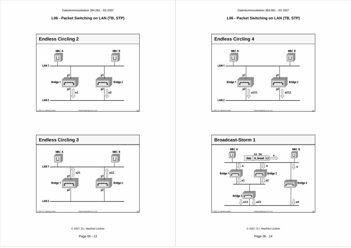
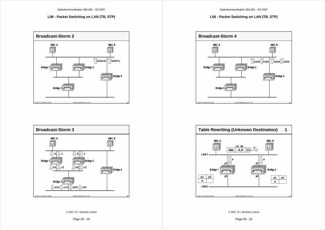
Parallel Paths
• parallel paths between two LAN segments cause– endless circling of frames with unknown destination
– endless circling of broadcast-frames
– endless circling of direct addressed frames during flooding phase
– blocking of buffer-resources
• parallel paths in a more complex topology cause– overflow of all buffer-resources and stagnation of the
LANs
– Broadcast Storm
• to avoid these effects– Spanning Tree Protocol (STP)
© 2007, D.I. Manfred Lindner Packet Switching on L2, v4.9 24
Endless Circling 1
data A, broad L2SA DA
MAC A MAC B
Bridge 1 Bridge 2
p1
p2
p1
p2
LAN 1
LAN 2
a
a a
Datenkommunikation 384.081 - SS 2007
L06 - Packet Switching on LAN (TB, STP)
© 2007, D.I. Manfred Lindner
Page 06 - 13
© 2007, D.I. Manfred Lindner Packet Switching on L2, v4.9 25
Endless Circling 2
MAC A MAC B
Bridge 1 Bridge 2
p1
p2
p1
p2
LAN 1
LAN 2
a1 a2
© 2007, D.I. Manfred Lindner Packet Switching on L2, v4.9 26
Endless Circling 3
MAC A MAC B
Bridge 1 Bridge 2
p1
p2
p1
p2
LAN 1
LAN 2
a21 a12
Datenkommunikation 384.081 - SS 2007
L06 - Packet Switching on LAN (TB, STP)
© 2007, D.I. Manfred Lindner
Page 06 - 14
© 2007, D.I. Manfred Lindner Packet Switching on L2, v4.9 27
Endless Circling 4
MAC A MAC B
Bridge 1 Bridge 2
p1
p2
p1
p2
LAN 1
LAN 2
a121 a212
© 2007, D.I. Manfred Lindner Packet Switching on L2, v4.9 28
Broadcast-Storm 1
MAC A MAC B
Bridge 1
data A, broad L2SA DA a
a a
a1 a2
Bridge 2
Bridge 3
Bridge 4
a13 a23
a
a4
Datenkommunikation 384.081 - SS 2007
L06 - Packet Switching on LAN (TB, STP)
© 2007, D.I. Manfred Lindner
Page 06 - 15
© 2007, D.I. Manfred Lindner Packet Switching on L2, v4.9 29
Broadcast-Storm 2
MAC A MAC B
Bridge 1 Bridge 2
Bridge 3
Bridge 4
a134=b a234=c
© 2007, D.I. Manfred Lindner Packet Switching on L2, v4.9 30
Broadcast-Storm 3
MAC A MAC B
Bridge 1
c
c1
Bridge 2
Bridge 3
Bridge 4
c13 c23
b
b1
c
c2
b
b2
b13 b23
Datenkommunikation 384.081 - SS 2007
L06 - Packet Switching on LAN (TB, STP)
© 2007, D.I. Manfred Lindner
Page 06 - 16
© 2007, D.I. Manfred Lindner Packet Switching on L2, v4.9 31
Broadcast-Storm 4
MAC A MAC B
Bridge 1 Bridge 2
Bridge 3
Bridge 4
b134 c234c134 b234
© 2007, D.I. Manfred Lindner Packet Switching on L2, v4.9 32
Table Rewriting (Unknown Destination) 1
data A, B L2SA DA
MAC A MAC B
Bridge 1 Bridge 2
p1
p2
p1
p2
LAN 1
LAN 2
a
a a
p1 p2
Ap1 p2
A
Datenkommunikation 384.081 - SS 2007
L06 - Packet Switching on LAN (TB, STP)
© 2007, D.I. Manfred Lindner
Page 06 - 17
© 2007, D.I. Manfred Lindner Packet Switching on L2, v4.9 33
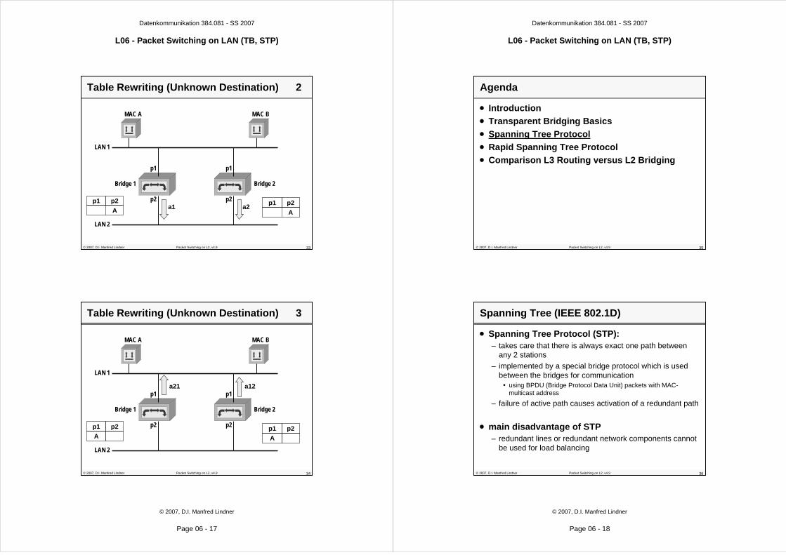
Table Rewriting (Unknown Destination) 2
MAC A MAC B
Bridge 1 Bridge 2
p1
p2
p1
p2
LAN 1
LAN 2
a1 a2p1 p2
Ap1 p2
A
© 2007, D.I. Manfred Lindner Packet Switching on L2, v4.9 34
Table Rewriting (Unknown Destination) 3
MAC A MAC B
Bridge 1 Bridge 2
p1
p2
p1
p2
LAN 1
LAN 2
a21 a12
p1 p2
Ap1 p2
A
Datenkommunikation 384.081 - SS 2007
L06 - Packet Switching on LAN (TB, STP)
© 2007, D.I. Manfred Lindner
Page 06 - 18
© 2007, D.I. Manfred Lindner Packet Switching on L2, v4.9 35
Agenda
• Introduction
• Transparent Bridging Basics
• Spanning Tree Protocol
• Rapid Spanning Tree Protocol
• Comparison L3 Routing versus L2 Bridging
© 2007, D.I. Manfred Lindner Packet Switching on L2, v4.9 36
• Spanning Tree Protocol (STP):– takes care that there is always exact one path between
any 2 stations
– implemented by a special bridge protocol which is used between the bridges for communication
• using BPDU (Bridge Protocol Data Unit) packets with MAC-multicast address
– failure of active path causes activation of a redundant path
• main disadvantage of STP– redundant lines or redundant network components cannot
be used for load balancing
Spanning Tree (IEEE 802.1D)

Datenkommunikation 384.081 - SS 2007
L06 - Packet Switching on LAN (TB, STP)
© 2007, D.I. Manfred Lindner
Page 06 - 19
© 2007, D.I. Manfred Lindner Packet Switching on L2, v4.9 37
Parameters for STP 1
• Bridge Identifier (Bridge ID)– combination of MAC-address and a priority number
• typically, the lowest MAC-address of all ports is used for that
• note: although bridge will not be seen by end systems, for bridge communication and management purposes a bridge will listen to one or more dedicated MAC addresses
• Bridge-ID = priority# (2 Byte) + mac# (6 Byte)
– priority number can be configured by the administrator• default value is 32768
– lowest Bridge ID has highest priority• lowest configured priority number
– if you keep default values• the bridge with the lowest MAC address will have the highest
priority
© 2007, D.I. Manfred Lindner Packet Switching on L2, v4.9 38
Parameters for STP 2
• Port Cost (C)– costs in order to access local interface– inverse proportional to the transmission rate– default cost = 1000 / transmission rate in Mbit/s
• so 10 Mbit/s Ethernet has a default Path Cost of 100• with occurrence of 1Gbit/s Ethernet rule was adapted
– 100 Mbit/s = 19, 1Gbit/s = 4, 10Gbit/s = 2
– can be configured to a different value by the administrator
• Port Identifier (Port ID)– combination of port number and a priority number
• Port-ID = port priority#.port#
– configured by the administrator• default port priority = 128
Datenkommunikation 384.081 - SS 2007
L06 - Packet Switching on LAN (TB, STP)
© 2007, D.I. Manfred Lindner
Page 06 - 20
© 2007, D.I. Manfred Lindner Packet Switching on L2, v4.9 39
Parameters for STP Example
Bridge 1 ID = 42
Bridge 3 ID = 45
Bridge 4 ID = 57
Bridge 5 ID = 83
Bridge 2 ID = 97
C=10
C=10
C=10
C=10
C=05
C=05
C=05
C=05
C=10
C=05 C=05
LAN 2
LAN 1
LAN 5
LAN 3 LAN 4
© 2007, D.I. Manfred Lindner Packet Switching on L2, v4.9 40
Spanning Tree applied
Bridge 1
Bridge 3 Bridge 4
Bridge 5
Bridge 2
LAN 2
LAN 1
LAN 5
LAN 3 LAN 4

Datenkommunikation 384.081 - SS 2007
L06 - Packet Switching on LAN (TB, STP)
© 2007, D.I. Manfred Lindner
Page 06 - 21
© 2007, D.I. Manfred Lindner Packet Switching on L2, v4.9 41
Spanning Tree Terms
Bridge 1
Bridge 3 Bridge 4
Bridge 5
Bridge 2
LAN 2
LAN 1
LAN 5
LAN 3 LAN 4
Root Bridge Root Bridge
Root Port Root Port Root Port Root Port
Root Port Root Port
Root Port Root Port
Designated Bridge Designated Bridge for LAN 5for LAN 5
Designated Bridge Designated Bridge for LAN 3 and LAN 4for LAN 3 and LAN 4
Designated Port Designated Port Designated Port Designated Port
Designated Port Designated Port Designated Port Designated Port
Designated Port Designated Port
© 2007, D.I. Manfred Lindner Packet Switching on L2, v4.9 42
Spanning Tree Algorithm Summary
– select the root bridge
– select the root ports• by computation of the shortest path from any other bridge to the
root bridge
• root port points to the shortest path towards the root
– select one designated bridge for every LAN segment which can be reached by more than one bridge
• corresponding port is called designated port
– set the designated and root ports in forwarding state
– set all other ports in blocking state
– creates single paths from the root to all leaves (LAN segments) of the network
Datenkommunikation 384.081 - SS 2007
L06 - Packet Switching on LAN (TB, STP)
© 2007, D.I. Manfred Lindner
Page 06 - 22
© 2007, D.I. Manfred Lindner Packet Switching on L2, v4.9 43
Format of STP Messages - BPDU Format
BPDU ...................... Bridge Protocol Data Unit (OSI term for this kind ofmessage)
Root ID ....................... Who seems to be or who is the root bridge (R-ID)?
Root Path Cost ......... How far is the root bridge away from me (RPC)?
Bridge ID .................... ID of bridge transmitting this BPDU (O-ID)
Port ID ........................ port over which this BPDU was transmitted (P-ID)
Prot.ID
2 Byte
Prot.Vers.
1 Byte
BPDU Type
1 Byte
Flags
1 Byte
Root ID
8 Byte
RootPath
Costs
4 Byte
Bridge ID
8 Byte
Port ID
2 Byte
Mess.Age
2 Byte
MaxAge
2 Byte
HelloTime
2 Byte
Fwd.Delay
2 Byte
© 2007, D.I. Manfred Lindner Packet Switching on L2, v4.9 44
BPDU Fields 1
– Protocol Identifier:
– 0000 (hex) for STP 802.1D
– Protocol Version:
– 00 (hex) for version 802.1D (1998)
– 02 (hex) for version 802.1D (2004)
– BPDU Type:
– 00 (hex) for Configuration BPDU
– 80 (hex) for Topology Change Notification (TCN) BPDU
– Root Identifier:
– 2 bytes for priority (default 32768)
– 6 bytes for MAC-address
– Root Path Costs in binary representation:
– range 1-65535
– Bridge Identifier:
– structure like Root Identifier

Datenkommunikation 384.081 - SS 2007
L06 - Packet Switching on LAN (TB, STP)
© 2007, D.I. Manfred Lindner
Page 06 - 23
© 2007, D.I. Manfred Lindner Packet Switching on L2, v4.9 45
BPDU Fields 2
– Port Identifier:
– 1 byte priority (default 128)
– 1 byte port number
– Message Age (range 1-10s):
– age of Configuration BPDU
– transmitted by root-bridge initially using zero value, each passing-on (by designated bridge) increases this number
– Max Age (range 6-40s):
– aging limit for information obtained from Configuration BPDU
– basic parameter for detecting idle failures (e.g. root bridge = dead)
– default 20 seconds
– Hello Time (range 1-10s):
– time interval for generation of periodic Configuration BPDUs by root bridge
– default 2 seconds
© 2007, D.I. Manfred Lindner Packet Switching on L2, v4.9 46
BPDU Fields 3
– Forward Delay (range 4-30s):– time delay for putting a port in the forwarding state
– default 15 seconds
– but that means 15 seconds listening plus 15 seconds learning
– Hello Time, Max Age, Forward Delay are specified by Root-Bridge
– Flags (a "1" indicates the function):– bit 8 ... Topology Change Acknowledgement (TCA)
– bit 1 ... Topology Change (TC)
– used in TCN BPDU’s for signalling topology changes – note: in case of a topology change MAC addresses should
change to another port in the bridging table (convergence)
– therefore a relearning of the dynamic bridging table is necessary; relearning is triggered by the root bridge by TCN
Datenkommunikation 384.081 - SS 2007
L06 - Packet Switching on LAN (TB, STP)
© 2007, D.I. Manfred Lindner
Page 06 - 24
© 2007, D.I. Manfred Lindner Packet Switching on L2, v4.9 47
MAC Addresses / LLC / Network Diameter
• bridges use for STP-communication:– multicast address:
0180 C200 0000 hex
0180 C200 0001 to 0180 C200 000F are reserved
0180 C200 0010 hex All LAN Bridges Management Group Address
– the DSAP/SSAP of LLC header42 hex Bridge Spanning Tree Protocol
• Maximum Bridge Diameter– maximum number of bridges between any two end
systems is 7 using default values for hello time, forward delay and max age
• For details of STP operation look to corresponding chapter in “Collection of all lectures of Manfred Lindner”
© 2007, D.I. Manfred Lindner Packet Switching on L2, v4.9 48
STP Error Detection
• normally the root bridge generates (triggers)– every 1-10 seconds (hello time interval) a Configuration
BPDU to be received on the root port of every other bridge and carried on through the designated ports
– bridges which are not designated are still listening to such messages on blocked ports
• if triggering ages out two scenarios are possible– root bridge failure
• a new root bridge will be selected based on the lowest Bridge-ID and the whole spanning tree may be modified
– designated bridge failure• if there is an other bridge which can support a LAN segment this
bridge will become the new designated bridge

Datenkommunikation 384.081 - SS 2007
L06 - Packet Switching on LAN (TB, STP)
© 2007, D.I. Manfred Lindner
Page 06 - 25
© 2007, D.I. Manfred Lindner Packet Switching on L2, v4.9 49
STP Convergence Time – Failure of Designated Bridge
• Time = max age (20 sec) + 2*forward delay (15 sec Listening + 15 sec Learning) = 50 sec
Bridge 1
Bridge 3 Bridge 4
Bridge 5
Bridge 2
LAN 2
LAN 1
LAN 5
LAN 3 LAN 4
© 2007, D.I. Manfred Lindner Packet Switching on L2, v4.9 50
STP Convergence Time – Failure of Root Bridge
• Time = max age (20 sec) + 2*forward delay (15 sec Listening + 15 sec Learning) = 50 sec
Bridge 1
Bridge 3 Bridge 4
Bridge 5
Bridge 2
LAN 2
LAN 1
LAN 5
LAN 3 LAN 4
Datenkommunikation 384.081 - SS 2007
L06 - Packet Switching on LAN (TB, STP)
© 2007, D.I. Manfred Lindner
Page 06 - 26
© 2007, D.I. Manfred Lindner Packet Switching on L2, v4.9 51
STP Convergence Time – Failure of Root Port
• Time = 2*forward delay (15 sec Listening + 15 sec Learning) = 30 sec
Bridge 1
Bridge 4
Bridge 5
Bridge 2
LAN 2
LAN 1
LAN 5
LAN 3 LAN 4
© 2007, D.I. Manfred Lindner Packet Switching on L2, v4.9 52
Some STP Facts
• disadvantages of STP– active paths are always calculated from the root, but the
actual information flow of the network may use other paths• note: network-manager can control this via Bridge Priority, Path
Costs und Port Priority to achieve a certain policy under normaloperation
• hence STP should be designed to overcome plug and play behaviour of default values
– redundant paths cannot be used for load balancing• redundant bridges may be never used if there is no failure of the
currently active components• for remote bridging via WAN the same is true for redundant WAN
links
– convergence time between 30 and 50 seconds• to improve convergence time Rapid Spanning Tree Protocol has
been developed (802.1D version 2004)

Datenkommunikation 384.081 - SS 2007
L06 - Packet Switching on LAN (TB, STP)
© 2007, D.I. Manfred Lindner
Page 06 - 27
© 2007, D.I. Manfred Lindner Packet Switching on L2, v4.9 53
Agenda
• Introduction
• Transparent Bridging Basics
• Spanning Tree Protocol
• Rapid Spanning Tree Protocol
• Comparison L3 Routing versus L2 Bridging
© 2007, D.I. Manfred Lindner Packet Switching on L2, v4.9 54
Introduction
• Rapid Spanning Tree (RSTP)– IEEE 802.1D version 2004 (former IEEE 802.1w)– Can be seen as an evolution of the Spanning Tree
Protocol (STP; IEEE 802.1D)– Capable of reverting back to 802.1D version 1998– Convergence time reduced to few seconds !!!
• Terminology slightly changed– Blocking port role is split into the Backup and Alternate
port roles• Alternate port• Backup port
– Root port and Designated port roles still remain the same– New port state
• Discarding (see next slides for details)
Datenkommunikation 384.081 - SS 2007
L06 - Packet Switching on LAN (TB, STP)
© 2007, D.I. Manfred Lindner
Page 06 - 28
© 2007, D.I. Manfred Lindner Packet Switching on L2, v4.9 55
Port States Comparison
STP (802.1d)Port State
RSTP (802.1w)Port State
Is Port includedin active
Topology?
Is Port learningMAC addresses?
disabled discarding
discarding
discarding
learning
forwardingforwarding
learning
listening
blocking
No
No
No
No
NoYes
Yes
Yes
Yes
Yes
© 2007, D.I. Manfred Lindner Packet Switching on L2, v4.9 56
Port Roles
• Root Port Role– Receives the best BPDU (so it is closest to the root
bridge)
• Designated Port Role– A port is designated if it can send the best BDPU on the
segment to which it is connected
– On a given segment, there can be only one path toward the root-bridge
Datenkommunikation 384.081 - SS 2007
L06 - Packet Switching on LAN (TB, STP)
© 2007, D.I. Manfred Lindner
Page 06 - 29
© 2007, D.I. Manfred Lindner Packet Switching on L2, v4.9 57
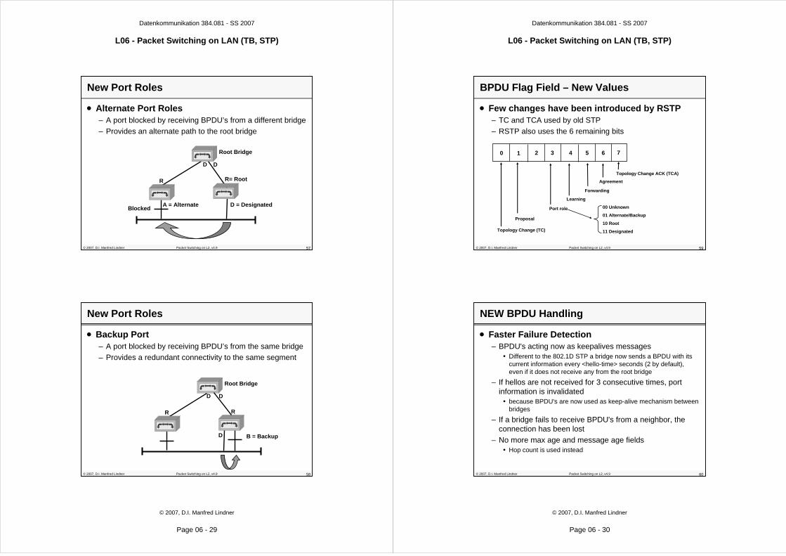
New Port Roles
• Alternate Port Roles– A port blocked by receiving BPDU’s from a different bridge
– Provides an alternate path to the root bridge
Root Bridge
R R= Root
D D
D = DesignatedA = AlternateBlocked
© 2007, D.I. Manfred Lindner Packet Switching on L2, v4.9 58
New Port Roles
• Backup Port– A port blocked by receiving BPDU’s from the same bridge
– Provides a redundant connectivity to the same segment
Root Bridge
R R
D D
D B = Backup
Datenkommunikation 384.081 - SS 2007
L06 - Packet Switching on LAN (TB, STP)
© 2007, D.I. Manfred Lindner
Page 06 - 30
© 2007, D.I. Manfred Lindner Packet Switching on L2, v4.9 59
BPDU Flag Field – New Values
• Few changes have been introduced by RSTP– TC and TCA used by old STP
– RSTP also uses the 6 remaining bits
0 1 2 3 4 5 6 7
Topology Change ACK (TCA)
Agreement
Forwarding
Learning
Port role
Proposal
Topology Change (TC)
00 Unknown
01 Alternate/Backup
10 Root
11 Designated
© 2007, D.I. Manfred Lindner Packet Switching on L2, v4.9 60
NEW BPDU Handling
• Faster Failure Detection– BPDU's acting now as keepalives messages
• Different to the 802.1D STP a bridge now sends a BPDU with its current information every <hello-time> seconds (2 by default), even if it does not receive any from the root bridge
– If hellos are not received for 3 consecutive times, port information is invalidated
• because BPDU's are now used as keep-alive mechanism between bridges
– If a bridge fails to receive BPDU's from a neighbor, the connection has been lost
– No more max age and message age fields• Hop count is used instead

Datenkommunikation 384.081 - SS 2007
L06 - Packet Switching on LAN (TB, STP)
© 2007, D.I. Manfred Lindner
Page 06 - 31
© 2007, D.I. Manfred Lindner Packet Switching on L2, v4.9 61
Proposal / Agreement
• Explicit handshake between bridges– Upon link up event the bridge sends a proposal to become
designated for that segment
– Remote bridge responses with an agreement if the port on which it received the proposal is the root port of the remote bridge
– As soon as receiving an agreement, bridge moves the port to the forwarding state
© 2007, D.I. Manfred Lindner Packet Switching on L2, v4.9 62
Proposal/Agreement Sequence
• Suppose a new link is created between the root and switch A and then a new switch B is inserted
P1
Root 1. Proposal
2. AgreementP1 Designated Port -> Forwarding StateP2 Root Port
A
P2
P1
Root1. Proposal
A
P2
B
P3 P4
2. AgreementP3 Designated Port
-> Forwarding StateP4 Root Port
Datenkommunikation 384.081 - SS 2007
L06 - Packet Switching on LAN (TB, STP)
© 2007, D.I. Manfred Lindner
Page 06 - 32
© 2007, D.I. Manfred Lindner Packet Switching on L2, v4.9 63
Rapid Transition to Forwarding State
• Most important feature in 802.1w
• The legacy STP was passively waiting for the network to converge before turning a port into the forwarding state
• New RSTP is able to actively confirm that a port can safely transition to forwarding
• Real feedback mechanism, that takes place between RSTP-compliant bridges
• To achieve fast convergence on a port, the protocol relies upon 2 new variables– Edge ports
– Link type
© 2007, D.I. Manfred Lindner Packet Switching on L2, v4.9 64
Rapid Transition to Forwarding State
• RSTP can only achieve rapid transition to forwarding– On edge ports– On point-to-point links (trunks between L2 switches)– But not on shared Ports
• Edge Ports– Ports, which are directly connected to end stations cannot
create bridging loops in the network and can thus directly perform on link setup transition to forwarding, skipping the listening and learning states
• Link type– Is automatically derived from the duplex mode of a port
• A port operating in full-duplex will be assumed to be point-to-point• A port operating in half-duplex will be assumed to be a shared port

Datenkommunikation 384.081 - SS 2007
L06 - Packet Switching on LAN (TB, STP)
© 2007, D.I. Manfred Lindner
Page 06 - 33
© 2007, D.I. Manfred Lindner Packet Switching on L2, v4.9 65
Accepting Inferior BPDU's
– B looses root port and sends BPDU claiming to be the root
– C immediately becomes designated for the blocked link between C and B and sends a proposal to B
– B sends an agreement and C set its port to forwarding
– Like Cisco's Backbone Fast
Inferior BPDU„I am the root“
B
C
Root
Indirect Failurefor Switch C
© 2007, D.I. Manfred Lindner Packet Switching on L2, v4.9 66
Accepting New Root Port BPDU's
– C looses root port and sends BPDU on the blocked link agreeing that this port is now root ort
– C set its port to forwarding
– Like Cisco's Uplink Fast
New Root Port,Put your Port intoForwarding State
B
C
Root
Direct Failurefor Switch C
Datenkommunikation 384.081 - SS 2007
L06 - Packet Switching on LAN (TB, STP)
© 2007, D.I. Manfred Lindner
Page 06 - 34
© 2007, D.I. Manfred Lindner Packet Switching on L2, v4.9 67
Slow Convergence with Legacy STP 1
B C
A
D
Root
P1
New ports coming up on the root and the switch A are immediately set in listening state, blocking traffic.
BPDU's from the root start propagating towards the leaves through A
A new link between A and Root is being added to the bridged network
© 2007, D.I. Manfred Lindner Packet Switching on L2, v4.9 68
Slow Convergence with Legacy STP 2
B C
A
D
Root
P1
Very quickly, the BPDU's from the root via A reach D that immediately blocks its port P1.
The topology has now converged, though, the network is disrupted for twice forward delay because A needs time for Listening and Learning on the new Port

Datenkommunikation 384.081 - SS 2007
L06 - Packet Switching on LAN (TB, STP)
© 2007, D.I. Manfred Lindner
Page 06 - 35
© 2007, D.I. Manfred Lindner Packet Switching on L2, v4.9 69
Fast Convergence with RSTP 1
B C
A
D
Root1
Both ports on link between A and the root are put in designated blocking as soon as they come up.
As soon as A receives the root´s BPDU, it blocks its non-edge designated ports (=“sync”). A explicitly authorizes the root bridge to put its port in forwarding
A new link between A and Root is being added to the bridged network
© 2007, D.I. Manfred Lindner Packet Switching on L2, v4.9 70
Fast Convergence with RSTP 2
B C
A
D
Root
2
The link between Switch A and the root is put in forwarding state.
The network is now blocking below Switch A. This cut will travel down the tree along with the BPDU's originated by the root through Switch A. At that stage, the newly blocked ports on Switch A will also negotiate a quick transition to forwarding with their neighboring ports in Switch B and Switch C, that both in turn will initiate a sync operation (especially C to D in our case)
Datenkommunikation 384.081 - SS 2007
L06 - Packet Switching on LAN (TB, STP)
© 2007, D.I. Manfred Lindner
Page 06 - 36
© 2007, D.I. Manfred Lindner Packet Switching on L2, v4.9 71
Fast Convergence with RSTP 3
B C
A
D
Root
3
Switch C blocks its designated port to D.
We have reached the final topology, which means that port P1 on D ends up blocking. It´s the same topology as for the STP example.
But we got this topology just in time necessary for the new BPDU's to travel down the tree. No timer has been involved in this quick convergence.
Convergence Time < 1 second
© 2007, D.I. Manfred Lindner Packet Switching on L2, v4.9 72
Topology Change Detection
• When a RSTP bridge detects a topology change, the following happens:– It starts the TC While timer with a value equal to twice the
hello time for all its non-edge designated ports and its root port if necessary
– It flushes the MAC addresses associated with all these ports
Datenkommunikation 384.081 - SS 2007
L06 - Packet Switching on LAN (TB, STP)
© 2007, D.I. Manfred Lindner
Page 06 - 37
© 2007, D.I. Manfred Lindner Packet Switching on L2, v4.9 73
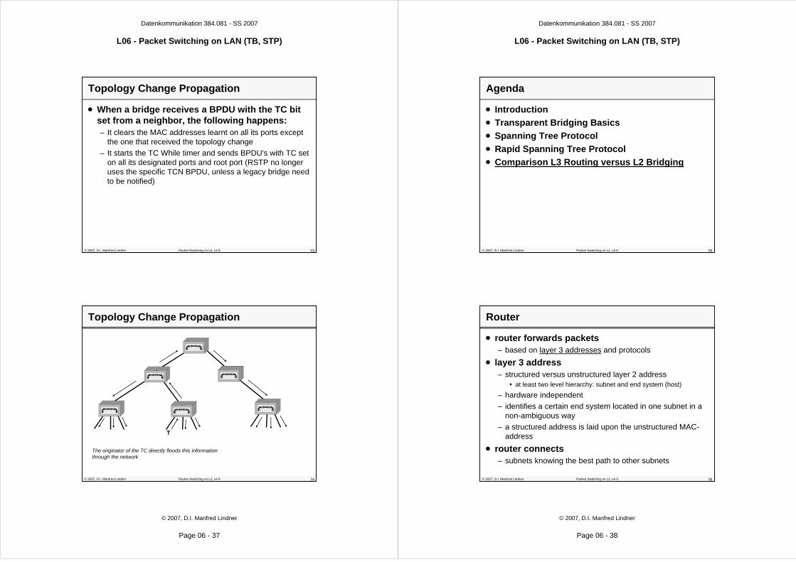
Topology Change Propagation
• When a bridge receives a BPDU with the TC bit set from a neighbor, the following happens:– It clears the MAC addresses learnt on all its ports except
the one that received the topology change
– It starts the TC While timer and sends BPDU's with TC set on all its designated ports and root port (RSTP no longer uses the specific TCN BPDU, unless a legacy bridge need to be notified)
© 2007, D.I. Manfred Lindner Packet Switching on L2, v4.9 74
Topology Change Propagation
The originator of the TC directly floods this information through the network
T
Datenkommunikation 384.081 - SS 2007
L06 - Packet Switching on LAN (TB, STP)
© 2007, D.I. Manfred Lindner
Page 06 - 38
© 2007, D.I. Manfred Lindner Packet Switching on L2, v4.9 75
Agenda
• Introduction
• Transparent Bridging Basics
• Spanning Tree Protocol
• Rapid Spanning Tree Protocol
• Comparison L3 Routing versus L2 Bridging
© 2007, D.I. Manfred Lindner Packet Switching on L2, v4.9 76
• router forwards packets– based on layer 3 addresses and protocols
• layer 3 address– structured versus unstructured layer 2 address
• at least two level hierarchy: subnet and end system (host)
– hardware independent
– identifies a certain end system located in one subnet in a non-ambiguous way
– a structured address is laid upon the unstructured MAC-address
• router connects– subnets knowing the best path to other subnets
Router

Datenkommunikation 384.081 - SS 2007
L06 - Packet Switching on LAN (TB, STP)
© 2007, D.I. Manfred Lindner
Page 06 - 39
© 2007, D.I. Manfred Lindner Packet Switching on L2, v4.9 77
Router and OSI Model
1
2
3
6
4
5
1
2
3
6
4
5
1
2
1
2router as relay
System A System B
LAN 1 LAN 2
port 1 port 2
7 7
3 3network protocol network protocol
transport protocol
local
© 2007, D.I. Manfred Lindner Packet Switching on L2, v4.9 78
Requirements for Routers
• consistent layer-3 functionality– for entire transport system– from one end-system over all routers in between to the
other end-system – hence routing is not protocol-transparent
• all elements must speak the same „language“
• end-system– must know about default router– on location change, end-system must adjust its layer 3
address
• to keep the routing tables consistent– routers must exchange information about the network
topology by using routing-protocols
Datenkommunikation 384.081 - SS 2007
L06 - Packet Switching on LAN (TB, STP)
© 2007, D.I. Manfred Lindner
Page 06 - 40
© 2007, D.I. Manfred Lindner Packet Switching on L2, v4.9 79
Routing Facts 1
• in contrast to bridges– router maintains only the subnet-part of the layer 3
addresses in its routing table
– the routing table size is direct proportional to the number of subnets and not to the number of end-systems
• transport on a given subnet– still relies on layer 2 addresses
• end systems forward data packets for remote destinations– to a selected router using the router's MAC-address as
destination
– only these packets must be processed by the router
© 2007, D.I. Manfred Lindner Packet Switching on L2, v4.9 80
Routing Facts 2
• flow control between router and end system is principally possible– end systems knows about the local router
• broadcast/multicast-packets in the particular subnet– are blocked by the router so broad/multicast traffic on the
subnets doesn't stress WAN connections
• independent of layer 1, 2– so coupling of heterogeneous networks is possible
• routers can use redundant paths – meshed topologies are usual
• routers can use parallel paths for load balancing

Datenkommunikation 384.081 - SS 2007
L06 - Packet Switching on LAN (TB, STP)
© 2007, D.I. Manfred Lindner
Page 06 - 41
© 2007, D.I. Manfred Lindner Packet Switching on L2, v4.9 81
Example Topology: Bridging
MAC A MAC B
MAC D
MAC C
Host B
B1 B4B2
B3
link deactivatedby spanning tree
Host A Host C
Host DBridging Table B3
MAC A s2
MAC B s2
MAC C s2
MAC D e0
Bridging Table B1
MAC A e0
MAC B e0
MAC C s2
MAC D s2
Bridging Table B4
MAC A s1
MAC B s1
MAC C e0
MAC D s1
Bridging Table B2
MAC A s1
MAC B s1
MAC C s3
MAC D s2
e0 e0
e0
s1
s2
s1 s2
s1
s2
s3
s1
© 2007, D.I. Manfred Lindner Packet Switching on L2, v4.9 82
Frame MAC A to MAC D (1)
MAC A MAC B
MAC D
MAC C
Host B
B1 B4B2
B3
link deactivatedby spanning tree
Host A Host C
Host D
MAC A -> MAC D
Bridging Table B1
MAC A e0
MAC B e0
MAC C s2
MAC D s2
s2
Datenkommunikation 384.081 - SS 2007
L06 - Packet Switching on LAN (TB, STP)
© 2007, D.I. Manfred Lindner
Page 06 - 42
© 2007, D.I. Manfred Lindner Packet Switching on L2, v4.9 83
Frame MAC A to MAC D (2)
MAC A MAC B
MAC D
MAC C
Host B
B1 B4B2
B3
link deactivatedby spanning tree
Host A Host C
MAC A -> MAC D
Bridging Table B2
MAC A s1
MAC B s1
MAC C s3
MAC D s2
s2
© 2007, D.I. Manfred Lindner Packet Switching on L2, v4.9 84
Frame MAC A to MAC D (3)
MAC A MAC B
MAC D
MAC C
Host B
B1 B4B2
B3
link deactivatedby spanning tree
Host A Host C
Host D
MAC A -> MAC D
Bridging Table B3
MAC A s2
MAC B s2
MAC C s2
MAC D e0
e0

Datenkommunikation 384.081 - SS 2007
L06 - Packet Switching on LAN (TB, STP)
© 2007, D.I. Manfred Lindner
Page 06 - 43
© 2007, D.I. Manfred Lindner Packet Switching on L2, v4.9 85
Frame MAC A to MAC D (4)
MAC A MAC B
MAC D
MAC C
Host B
B1 B4B2
B3
link deactivatedby spanning tree
Host A Host C
Host D
MAC A -> MAC D
e0
© 2007, D.I. Manfred Lindner Packet Switching on L2, v4.9 86
Example Topology: Generic Routing
L3 1.1Def-Gw 1.9
Host A
MAC A MAC B
MAC D
MAC T
MAC C
L3 1.2Def-Gw 1.9
Host B
L3 2.1Def-Gw 2.9
Host C
Host DL3 3.1
Def-Gw 3.9
R1R4
R2
R3
Net 1 Net 2
Net 3
Routing Table R1
1 local
2 R2
3 R3 s1
s2
e0
Routing Table R4
1 R2
2 local
3 R2 s2
e0
s1
Routing Table R3
1 R1
2 R2
3 local e0
s2
s1
Routing Table R2
1 R1
2 R4
3 R3 s2
s3
s1
next hop portnet-ID
1.9MAC R
2.9MAC S
e0 e0
s1
s2
s1 s2
s1
s2
s3
s1
e0
net-ID
host-ID
Datenkommunikation 384.081 - SS 2007
L06 - Packet Switching on LAN (TB, STP)
© 2007, D.I. Manfred Lindner
Page 06 - 44
© 2007, D.I. Manfred Lindner Packet Switching on L2, v4.9 87
Frame 1.1 to 3.1 (1)
MAC A MAC B
MAC D
MAC T
MAC C
R1 R4R2
R3
MAC A -> MAC R1.1 -> 3.1L3
L2
L3 1.1Def-Gw 1.9
Host A
L3 1.2Def-Gw 1.9
Host B
L3 2.1Def-Gw 2.9
Host C
Host DL3 3.1
Def-Gw 3.9
Net 1 Net 21.9MAC R
2.9MAC S
Net 3
Routing Table R1
1 local
2 R2
3 R3 s1
s2
e0
s1
© 2007, D.I. Manfred Lindner Packet Switching on L2, v4.9 88
MAC A MAC B
MAC D
MAC T
MAC C
R1 R4R2
R3L2 frame (e.g. HDLC)
1.1 -> 3.1L3L2
L3 1.1Def-Gw 1.9
Host A
L3 1.2Def-Gw 1.9
Host B
L3 2.1Def-Gw 2.9
Host C
Host DL3 3.1
Def-Gw 3.9
Net 1 Net 21.9MAC R
2.9MAC S
Frame 1.1 to 3.1 (2)
Net 3
Routing Table R3
1 R1
2 R2
3 local e0
s2
s1
e0

Datenkommunikation 384.081 - SS 2007
L06 - Packet Switching on LAN (TB, STP)
© 2007, D.I. Manfred Lindner
Page 06 - 45
© 2007, D.I. Manfred Lindner Packet Switching on L2, v4.9 89
MAC A MAC B
MAC D
MAC T
MAC C
R1 R4R2
R3
MAC T -> MAC D1.1 -> 3.1L3
L2
L3 1.1Def-Gw 1.9
Host A
L3 1.2Def-Gw 1.9
Host B
L3 2.1Def-Gw 2.9
Host C
Host DL3 3.1
Def-Gw 3.9
Net 1 Net 21.9MAC R
2.9MAC S
Frame 1.1 to 3.1 (3)
Net 3
© 2007, D.I. Manfred Lindner Packet Switching on L2, v4.9 90
OSI Comparison
• MAC addresses not routable– NetBIOS over NetBEUI
not routable (no L3)
• Bridge supports different physical media on each port– E.g. 10Mbit/s to
100Mbit/s
• Router supports different layer-2 technologies– E.g. Ethernet to Frame
Relay
Application
Transport
Network
Data Link
Physical
Session
Presentation
Application
Transport
Network
Data Link
Physical
Session
Presentation
Bridge
Application
Transport
Network
Data Link
Physical
Session
Presentation
Application
Transport
Network
Data Link
Physical
Session
Presentation
Router
Datenkommunikation 384.081 - SS 2007
L06 - Packet Switching on LAN (TB, STP)
© 2007, D.I. Manfred Lindner
Page 06 - 46
© 2007, D.I. Manfred Lindner Packet Switching on L2, v4.9 91
Transparent Bridging versus Routing
depends on MAC addresses only
Bridging Routing
requires structured addresses (must be configured)
invisible for end-systems; transparent for higher layers
end system must know its default-router
must process every frameprocesses only frames
addressed to it
number of table-entries = number of all devices in the
whole network
number of table-entries = number of subnets only
Spanning Tree eliminates redundant lines; no load balance
redundant lines and load balance possible
no flow control (may bechanged by usage of MAC
Pause command)
flow control is possible (router is seen by end systems)
© 2007, D.I. Manfred Lindner Packet Switching on L2, v4.9 92
Transparent Bridging versus Routing
no LAN/WAN coupling because of high traffic (broadcast
domain!)
Bridging Routing
does not stress WAN with subnet's broad- or multicasts; commonly used as "gateway"
paths selected by STP may not match communication behaviour
/ needs of end systems
router knows best way for each frame
faster, because implemented in HW; no address resolution
slower, because usually implemented in SW; address resolution (ARP) necessary
location change of an end-system does not require updating any addresses
location change of an end-system requires adjustment of
layer 3 address (may be solved by DHCP)

Datenkommunikation 384.081 - SS 2007
L06 - Packet Switching on LAN (TB, STP)
© 2007, D.I. Manfred Lindner
Page 06 - 47
© 2007, D.I. Manfred Lindner Packet Switching on L2, v4.9 93
Transparent Bridging versus Routing
spanning tree necessary against endless circling of frames and
broadcast storms
Bridging Routing
routing-protocols necessary to determine network topology
• but today's L2 switches can improve network performance by enabling full duplex, collision-free subnets
• MAC address resolution of routers is considered as unnecessary overhead -> trend goes to layer 3 switching (fast routing)
© 2007, D.I. Manfred Lindner Packet Switching on L2, v4.9 94
Most Important !
• bridge separates LAN into – multiple collision domains
• but a bridged network is still– one broadcast domain
– broadcast frames are always flooded
• router separates the whole Inter-network – into multiple broadcast domains
– broadcast frames arriving on a LAN are always stopped at the router
– they can´t leave their origin LAN
Datenkommunikation 384.081 - SS 2007
L06 - Packet Switching on LAN (TB, STP)
© 2007, D.I. Manfred Lindner
Page 06 - 48
© 2007, D.I. Manfred Lindner Packet Switching on L2, v4.9 95
Ethernet Switching
• “Ethernet Switch” is basically a bridge, differences are only:– faster because implemented in HW
– multiple ports
– improved functionality (e.g. VLAN)
• don't confuse it with WAN Switching!– e.g. X.25 switch, Frame Relay switch, ATM switch
– completely different!
LAN Switch