05631613
TRANSCRIPT

CAN Bus Network Design based on Bluetooth Technology
Xiaohong Ren Dept. of Automation & Electronic Engineering Sichuan University of Science and Engineering
Zigong, China [email protected]
Tianwen Wang Dept. of Automation & Electronic Engineering Sichuan University of Science and Engineering
Zigong, China [email protected]
Chenghua Fu Dept. of Automation & Electronic Engineering Sichuan University of Science and Engineering
Zigong, China [email protected]
Shuxiang Jia Dept. of Automation & Electronic Engineering Sichuan University of Science and Engineering
Zigong, China [email protected]
Abstract—The integration between Bluetooth technology and the field bus is an important item in the industry field application of the wireless communication. By the analysis of Bluetooth technology and the field bus network topology architecture, we put over the interconnect topology architecture based on Bluetooth wireless sensor network and CAN bus, also finish the system hardware design and software development that contains three components: CAN intelligent controller and CAN-Bluetooth intelligent master nodes based on the MCU8051 and Bluetooth sensor nodes based on MCU2051. We mainly resolved Bluetooth technology protocol and CAN bus protocol and realized the conversion between them. Experiments indicated that the system could operate reliably and steadily and CAN-Bluetooth nodes could deliver the data correctly transmitted from the Bluetooth wireless sensor nodes in real time to the upper computer to process through CAN bus intelligent controller.
Keywords- Bluetooth technology; CAN BUS; network topology; communication protocol; CAN-Bluetooth node; sensor node
I. INTRODUCTION In recent years, the application research of Bluetooth has
been paid greatly attention in industry field, since it is a good solution for short range wireless communication and replacement of short range cable. Bluetooth module's key features are low power, low cost, low complexity and robustness. Bluetooth modules operate in the unlicensed ISM (Industrial, Scientific, Medical) frequency band at 2.4MHz and avoids inferences from industry environment. Bluetooth radio adopts a fast acknowledgement and frequency hopping scheme to make the link robust, especially that it consists of sensor network has obviously anti-inferences in strong EMS environment. On the other hand, CAN (Controller Area Network) bus is one of the field bus most widely used in the world. International standard ISO11898 defines CAN bus as fully digital field control devices connection bus, can efficiently support the serial communication of the distribute control and the real time systems. CAN bus has been widely used in sensors, data acquisition, industrial control systems and
instrument device with high reliability, reality and flexibility. How to integrate the CAN bus wired technology with the Bluetooth wireless technology is a hot research task now. The paper gives a kind of design of CAN bus network based on Bluetooth technology, including CAN bus Bluetooth intelligent nods, sensors network with Bluetooth and the whole network architecture.
II. SYSTEM NETWORK TOPOLOGY ARCHITECTURE A network topology architecture, shown in Fig.1, is
constructed with the fusion of CAN bus and Bluetooth technology. Bluetooth technology provides point-to-point or point-to-many connection. A master node can has no more than seven slave nodes (be active at the same time),forming a star-type network with master-slave architecture called a picnet. If the master node in picnet is fused with CAN bus network node, we can get so-called CAN-Bluetooth intelligent node. In result, a picnet and another can be put on CAN bus, so that the two technology, ie. Wireless micro area network and field bus, are integrated, and further connected with Ethernet, finally the three levels topology architecture come out with industrial sensors wireless micro area network, field bus and industrial Ethernet. A picnet in the bottom also can produce so-called scatter networks to extend sensor network further through slave nodes. Considering the distribute features of spot sensors, limit power supply capacity, limit memory capability limit calculation ability and limit communication capability, the sensor nodes consist of cell, sensor element, measuring circuit, Bluetooth module, microcontroller and its soft system etc. and CAN-Bluetooth intelligent node is composed of CAN bus controller, CAN interface driver, Bluetooth module, micro controller and its soft system etc..
This work was supported by the Scientific Research Fund of Artificial Intelligence Key University Lab of Sichuan Province(2007R011).
2010 International Conference on Electrical and Control Engineering
978-0-7695-4031-3/10 $26.00 © 2010 IEEE
DOI 10.1109/iCECE.2010.144
560
2010 International Conference on Electrical and Control Engineering
978-0-7695-4031-3/10 $26.00 © 2010 IEEE
DOI 10.1109/iCECE.2010.144
560
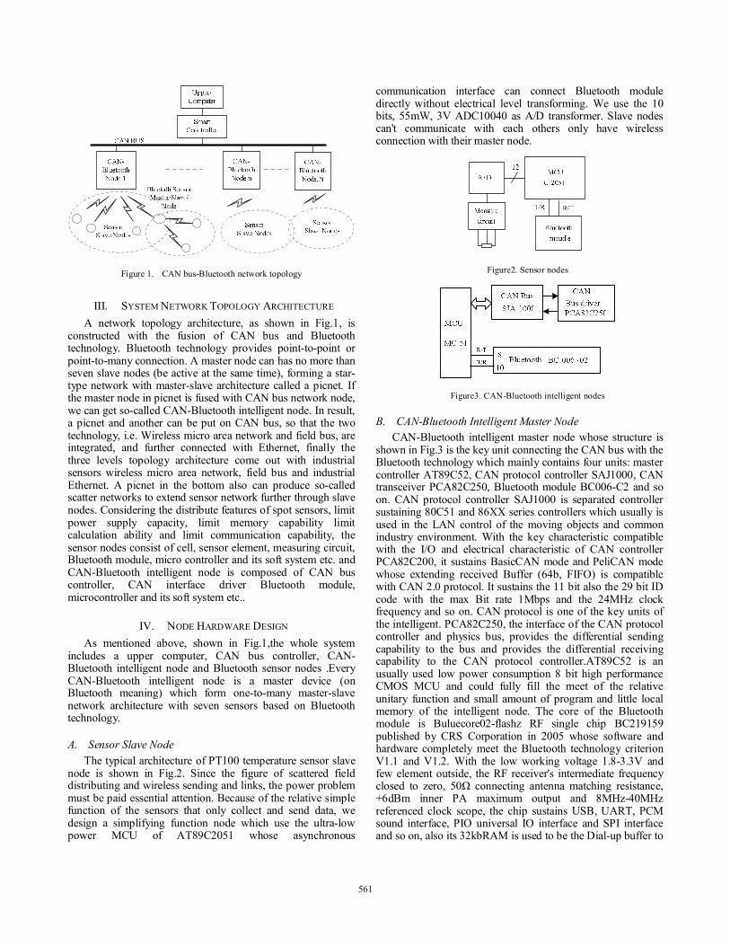
Figure 1. CAN bus-Bluetooth network topology
III. SYSTEM NETWORK TOPOLOGY ARCHITECTURE A network topology architecture, as shown in Fig.1, is
constructed with the fusion of CAN bus and Bluetooth technology. Bluetooth technology provides point-to-point or point-to-many connection. A master node can has no more than seven slave nodes (be active at the same time), forming a star-type network with master-slave architecture called a picnet. If the master node in picnet is fused with CAN bus network node, we can get so-called CAN-Bluetooth intelligent node. In result, a picnet and another can be put on CAN bus, so that the two technology, i.e. Wireless micro area network and field bus, are integrated, and further connected with Ethernet, finally the three levels topology architecture come out with industrial sensors wireless micro area network, field bus and industrial Ethernet. A picnet in the bottom also can produce so-called scatter networks to extend sensor network further through slave nodes. Considering the distribute features of spot sensors, limit power supply capacity, limit memory capability limit calculation ability and limit communication capability, the sensor nodes consist of cell, sensor element, measuring circuit, Bluetooth module, micro controller and its soft system etc. and CAN-Bluetooth intelligent node is composed of CAN bus controller, CAN interface driver Bluetooth module, microcontroller and its soft system etc..
IV. NODE HARDWARE DESIGN As mentioned above, shown in Fig.1,the whole system
includes a upper computer, CAN bus controller, CAN-Bluetooth intelligent node and Bluetooth sensor nodes .Every CAN-Bluetooth intelligent node is a master device (on Bluetooth meaning) which form one-to-many master-slave network architecture with seven sensors based on Bluetooth technology.
A. Sensor Slave Node The typical architecture of PT100 temperature sensor slave
node is shown in Fig.2. Since the figure of scattered field distributing and wireless sending and links, the power problem must be paid essential attention. Because of the relative simple function of the sensors that only collect and send data, we design a simplifying function node which use the ultra-low power MCU of AT89C2051 whose asynchronous
communication interface can connect Bluetooth module directly without electrical level transforming. We use the 10 bits, 55mW, 3V ADC10040 as A/D transformer. Slave nodes can't communicate with each others only have wireless connection with their master node.
Figure2. Sensor nodes
Figure3. CAN-Bluetooth intelligent nodes
B. CAN-Bluetooth Intelligent Master Node CAN-Bluetooth intelligent master node whose structure is
shown in Fig.3 is the key unit connecting the CAN bus with the Bluetooth technology which mainly contains four units: master controller AT89C52, CAN protocol controller SAJ1000, CAN transceiver PCA82C250, Bluetooth module BC006-C2 and so on. CAN protocol controller SAJ1000 is separated controller sustaining 80C51 and 86XX series controllers which usually is used in the LAN control of the moving objects and common industry environment. With the key characteristic compatible with the I/O and electrical characteristic of CAN controller PCA82C200, it sustains BasicCAN mode and PeliCAN mode whose extending received Buffer (64b, FIFO) is compatible with CAN 2.0 protocol. It sustains the 11 bit also the 29 bit ID code with the max Bit rate 1Mbps and the 24MHz clock frequency and so on. CAN protocol is one of the key units of the intelligent. PCA82C250, the interface of the CAN protocol controller and physics bus, provides the differential sending capability to the bus and provides the differential receiving capability to the CAN protocol controller.AT89C52 is an usually used low power consumption 8 bit high performance CMOS MCU and could fully fill the meet of the relative unitary function and small amount of program and little local memory of the intelligent node. The core of the Bluetooth module is Buluecore02-flashz RF single chip BC219159 published by CRS Corporation in 2005 whose software and hardware completely meet the Bluetooth technology criterion V1.1 and V1.2. With the low working voltage 1.8-3.3V and few element outside, the RF receiver's intermediate frequency closed to zero, 50Ω connecting antenna matching resistance, +6dBm inner PA maximum output and 8MHz-40MHz referenced clock scope, the chip sustains USB, UART, PCM sound interface, PIO universal IO interface and SPI interface and so on, also its 32kbRAM is used to be the Dial-up buffer to
561561

preserve the sound data and the universal memory of Bluetooth stack. Otherwise it owns 8Mb flash memory, supports point-to-point and point-to-many network topological architecture which can form the picnet and the scatter-net.
vcc
CA
NB
US
Figure4. Bluetooth-CAN master node hardware
C. CAN Bus Intelligent Controller In view of CAN bus system , CAN intelligent controller
acts as a master node ,and the CAN-Bluetooth intelligent node as a slave node in the whole CAN-Bluetooth network . CAN bus works in the multi-master mode without the difference of master and slave. CAN intelligent controlleris is responsible for the CAN bus communicatinn with the upper computer, it can exchange the data with the upper computer through RS232, meanwhile have the control of the field Bluetooth sensor nodes (broken, connection,etc.) from the upper computer. The upper computer supplies a friendly man-machine interface, trendencyl, data preserving, realizes the supervisory to the whole system, CAN node coordinating and uploading the collecting information and so forth.We choose the micro controller AT89C52 as the CAN bus controller, SAJ1000 as CAN protocol controller, PCA82C250 as CAN interface drives and the prolate data memory and the like.
V. PROTOCOL DESIGN The designed flow chart of the system software is shown in Fig.5. Bluetooth master and slave node communicate with their micro controller by the asynchronous communicate interface UART which initializes and sends instruction to the module by the onboard serial port (TXD/RXD) and receives data gained by the slave node form the master node. The eighth pin of the Bluetooth module acts as the MCU serial input RXD connected to the transmitting end, also the tenth pin as the MCU serial output TXD connected to the receiving end. After the interlink of the master nodes and the slave nodes, MUC packages the data as the universal CAN bus frame and send it to the CAN BUS by SAJ1000 when the data collected by the slave nodes is send to the master nodes. After getting the report, the CAN BUS reads the Bluetooth node data and transmits it to the upper computer according to universal frame (CAN bus controller is responsible).
Watch Dog Initiation
Initiate Serial Port
External InterruptInitiation
Feed DogCommand
Serial Port DaterSending Finish?
Receiving CANBus Information
Receiving InformationSended to Serial Port
Sending CAN Data Finish?
Receiving SerialPortInformation
Send Data To CAN
Y
N
Y
N
Initiate SJA1000
Power-on Reset MCU
Y
Figure5. System software design flow chart
Bluetooth intelligent master nodes operate the devises according to the order getting form CAN BUS when there is a operation to the local node device (cutting links,devices interlink etc.) on the CAN bus. The protocol design mainly includes two parts: the making of CAN-BUS-Bluetooth communication protocol conversion and the definition of the RS232 serial port data formate (CAN-RS232 connecting to the upper computer).
A. Brief of Bluetooth Protocol Stackr Bluetooth core system contains the RF radio
transceivers,base band and the protocol stack. Bluetooth protocol stack includes the RF layer,base band,LMP,L2CAP and SDP made by the assigned protocol of the SIG. When Bluetooth devices are transmitting data,base band part makes the data from high-rise protocol channel coding then downwards transmits it by RF.When Bluetooth devices are receiving data,RF will demodulates and furbishes aerial data and upwards transmit to the base band which then decodes it and send it to the high rise. Together with the LMP,the base
562562

band ensure RF between each Bluetooth device constitute physical connect. Base band data subgroups supply two physical styles: SOC (Synchronous Connection-Oriented) and ACL (Asynchronous Connectionless). ACL is adopt to data (subgroup) transmit with a data rata of 7723.2Kbps downstream and 57.6Kbps upstream asymmetrically or 433.9 Kbps symmetrically. There is only one ACL connect between the master station and all the enabled slave station and only the slave device of addressing could answer. LMP control and arrange all the relational link operation between two Bluetooth devices which contains establishing and controlling logical transmit and logical link meanwhile also controlling the physical layer. Through this protocol,the transmit-receive link manager recognizes and filter the signal rather than sending it to the higher-rise protocol. L2CAP is upper level protocol of the base band,it packets switching the data of the base band to the data mode fit for the high-rise using which supply protocol multiplex and quality of service exchange etc.. It is bridge of different length of protocol data units. Service search protocol is the foundation of all the user pattern which is used to search device and search format to establish the relationship around all the Bluetooth devices.Beside the protocol,V2.0 has defined the HCI which supplies the order interface of the base band controller,the link manager,the hardware situation and control register and universal order mode for user to access Bluetooth hardware device,also is the access interface of the hardware parameter configuration. In the practical application ,MCU (Bluetooth master) can directly control the Bluetooth chip through HCI to accomplish the communication control towards Bluetooth chip and make the application developing.Bluetooth devices have four operation modes:disconnected mode (standby and search mode),connecting mode (call and link mode),activity mode (data transmitting and receiving) and the low power consumption mode. Activity mode is the normal work mode,otherwise the low power consumption mode is for energy conservation which includes the Snif mode,Hold mode and Park mode among which Park mode has the lowest power consumption. We choose the MCU as both the master nodes and the slave nodes. Program design involves two key parts:the wireless connect of Bluetooth master-slave nodes and data connect style of it. The former is wireless then the later is wired.Since we choose the unattached MCU MCS51,the information exchange between Bluetooth master-slave nodes and CAN bus is completed by the MCU. Then it avoids the direct transform between CAN protocol and Bluetooth protocol which exchanges data only through the memory of the MCU. So Bluetooth program and CAN bus program could be designed separated.
B. CAN Bus-Bluetooth Communication Protocol Establishment
The foundation of this protocol is the data frames transmit based on CAN BUS and the serial port of the Bluetooth wireless transmit module. We define the application layer protocol.Considering the Bite unit in the serial port data
transmit while data frames format in CAN BUS transmit meanwhile this protocol mainly used in the industry field and auto control field,we adopt the short institute frames style. ID distribution of CAN BUS are as follows:
address 16 17 18 19 20 ID style Data
length Data style
Source device address
Aim device address
State information
Data length:mainly include the number of each frame of data and whether or not the long-distance frame information.Data syle:mainly include institution style and data style of the node for example AD,DC, motion style and the control style.Source device address:mainly include the address of the transmitting data node. Aim device address:mainly include the address of the receiving data node. State information:mainly include the state of the devices for example initializing of Bluetooth nodes,the successor failure connection and the relative information of the other devices.RS232 serial port data style are as follows:
Byte No1
Byte No2
Byte No3
ByteNo4 Byte No5 Byte No6-13
Data length
Data style
Source device address
Destination device address
State information
Data
Considering the low address part of CAN bus arbitration and the distributing principle of the optional device,we use 0XX00 as the upper computer card,0X01-0X07 as all kinds of control device for example the handle,control stick and the console etc.and the others as the address of each module node.After the data has reached the serial port it's transformed into the universal data frames format and stored in the BUFFER-R of the MCU. If CAN bus is idle the data in the BUFFER-R is transmitted into CAN sending function and send immediately. If CAN bus is busy the data is transmitted into the BUF-R of the ROM 6264. Waiting until the bus is idle then it's transmitted and the BUFFER-R could get new serial port data.When the data has reached the CAN bus it's transform into the universal data format fist and then logging into the BUFFER-C and send immediately if the serial port is idle. The data in the BUFFER-C is transmitted to the serial port sending function and send. If the serial port is busy the data is stored into BUF-C of the ROM6264. When the serial port is idle the data is transmitted meanwhile the BUFFER-C gets ready for receiving new data from CAN bus.
C. Data Format Example Taking a frame of Bluetooth set instruction as an example.
Data primitive: 02 12 0F 0E 06 2A. The analysis is as the following: [02] as the data length shows there is two data [06], [2A], [12] as the data style that is defined as: [10] Bluetooth fault, [11] Bluetooth hint message, [12] Bluetooth set, [13] Bluetooth data. The source device address [0F] means the address of the sending data node. The target device address [0E] means the address of the receiving data device. [06] and [2A] present the connecting Bluetooth handle and style, [06] presents the device linkage, [2A] presents the connecting device handle, that is the NO2A device. Taking the following frame of Bluetooth data instruction. Data primitive:03 13 0C 0E 29 12 08.The analysis is as the following: [03] as the data
563563

length means that there is three length [29], [12] and [08]. [13] presents Bluetooth data frame is unitary with the define of the data style. The source device address [0C] means the address of the sending data node. The target device address [0E] means the address of the receiving data device. [29] sends the handle number of Bluetooth device. [12] and [08] presents the sending data of Bluetooth device.
VI. CONCLUSION The debug result shows that the system can still accurately,
fast and steadily transmit data in the strong interference environment (electric drill as the interference source). As shown in Fig.6, the curve is the real-time tendency of the temperature signal from several Bluetooth nodes transmitted to the computer through the CAN bus. The research of the fusion of short distance wireless communication technology and the CAN bus extends the application of field bus in the special industry environment, which makes effectively extend the field bus network towards the low layer. Meanwhile, the field bus supplies the access for the short distance wireless network topology to connect to higher network (such as Ethernet network). It will be an important communication network technology in the automation field and must have a good prospect of application.
Figure6. Node temperature real-time curve
ACKNOWLEDGMENT
This work was supported by the Scientific Research Fund of Artificial Intelligence of Key University Lab of Sichuan Province (2007R011).
REFERENCES [1] Chun Jin. Bluetooth technology. Beijing Electron Industry Press,March
2001. [2] Chun Jin,Jinchao Lin,Baohong Wan. Bluetooth protocol with the source
code analysis. Beijing National Defense industry Press,June 2006. [3] Cambridge Silicon Radio Limited.Blue Core Flash HCIstack1.1v17.3.4
Software Release Note,August 2003. [4] Kuanming Wu. CAN BUS theory and application design.Beijing
University of Aeronautics and Astronautics Press,1996. [5] Xiaohong Ren,Chenghua Fu,Ke Hu.Wireless Data Aquisition System
based on Bluetooth Technology.Measurement and Control Technology,1(1),V128,2009.
[6] Fangkui Ma,Ji Huan.Integration and Development of Bluetooth Technology in Industry Control System. Beijing University of Aeronautics and Astronautics Press,12(32):1459-1462,2006.
[7] Winbond Electroics Corp.W77E58 Standard Book, 2005. [8] Zhaoqing Li.PC and Singlechip data communication technology.Beijing
University of Aeronautics and Astronautics Press, 2002. [9] Ping Chen,Yan Chen.Temperature Data Aquisition System based on
Bluetooth Technology. Instrument Technique and Sensor, 11:40-42,2005.
[10] Bilstrup U,Wiberg P.Bluetooth in industrial Environment.IEEE International Workshop on Factory Communication Systems,IEEE,239-246,2000.
[11] Daniele Miorandi,Stefanoo Vitturi.A wireless extension of Profibus DP Based on the Bluetooth Radio System.Ad Hoc Networks,3:479-494,2005.
[12] Soo-Hwan Choi,Byung-Kugkim,Jinwoopark,Chul-Heekang,Doo-Seop Eom.AN Implementation of Wireless Sensor Network for Security System Using Bluetooth.IEEE Transaction on Consumer Electronics,1{50},February 2004.
[13] Zdenek Bradac,Petr Fiedler,Pertr Cach,Radimir Vrba.Wireless Communication in Automation.Electronics,Circuits and System,2{2}:659-662,2003.
[14] Shangfeng DU,Xiaozhong Cao,Jin Xiong.CAN BUS measurement and control technology with its application.Beijing Electron Industry Press,January 2007.
564564