0559509 geo+report jt client - san bernardino county · professional service industries, inc. ......
TRANSCRIPT


CONTENTS PAGE NO.
PROJECT INFORMATION ........................................................................................................... 3 PROJECT AUTHORIZATION ........................................................................................................... 3 PROJECT DESCRIPTION ............................................................................................................... 3 PURPOSE AND SCOPE OF SERVICES ............................................................................................ 4
SITE AND SUBSURFACE CONDITIONS .................................................................................... 4 SITE LOCATION AND DESCRIPTION ............................................................................................... 4 REGIONAL GEOLOGY ................................................................................................................... 5 REGIONAL SEISMICITY ................................................................................................................. 5 SUBSURFACE CONDITIONS .......................................................................................................... 5 PERCOLATION TEST INFORMATION ............................................................................................... 7 GROUNDWATER INFORMATION ..................................................................................................... 7 LABORATORY TESTING ................................................................................................................ 7
CONCLUSIONS AND RECOMMENDATIONS ............................................................................ 8 GENERAL .................................................................................................................................... 8 EARTHQUAKE AND SEISMIC DESIGN CONSIDERATIONS ................................................................. 8 SITE PREPARATION & GRADING ................................................................................................. 10 UTILITY TRENCH CONSTRUCTION ............................................................................................... 12 TEMPORARY EXCAVATION CONSIDERATIONS .............................................................................. 13 SHALLOW FOUNDATIONS ........................................................................................................... 13 INTERIOR FLOOR SLABS ............................................................................................................ 14 PAVEMENT DESIGN.................................................................................................................... 15 CONSTRUCTION CONSIDERATIONS ............................................................................................. 16 PLAN REVIEW ............................................................................................................................ 17 OBSERVATION AND TESTING DURING CONSTRUCTION ................................................................ 17
REPORT LIMITATIONS ............................................................................................................. 17 APPENDIX
SITE VICINITY MAP ................................................................................................................. FIGURE 1 BORING LOCATION MAP .......................................................................................................... FIGURE 2 BORING LOGS LABORATORY TEST RESULTS STANDARD GUIDELINES FOR GRADING PROJECTS

DYNAMIC DEVELOPMENT COMPANY, LLC PSI REPORT 0559509 PROPOSED RETAIL/COMMERCIAL DEVELOPMENT JULY 6, 2011 NW CORNER TWENTYNINE PALMS HIGHWAY & SUNBURST STREET, JOSHUA TREE, CA
PROFESSIONAL SERVICE INDUSTRIES, INC.
PROJECT INFORMATION PROJECT AUTHORIZATION Professional Service Industries, Inc. (PSI) has completed a geotechnical exploration for the proposed retail/commercial development to be located in the northwest quadrant of the intersection of Twentynine Palms Highway (California State Route 62) and Sunbrust Street, in Joshua Tree, San Bernardino County, California. Mr. Michael Ward of Dynamic Development Company, LLC authorized our services on June 16, 2011 by signing the ‘Dynamic Development - Work Order Form’ for Geotechnical and Environmental Services. PROJECT DESCRIPTION Mr. Michael Ward of Dynamic Development Company, LLC provided the project information as described herein to PSI. Based on the information provided, PSI understands that the proposed project includes the construction of a retail/commercial development to be in the northwest quadrant of the intersection of Twentynine Palms Highway (California State Route 62) and Sunburst Street, in Joshua Tree, San Bernardino County, California. A Site Vicinity Map showing the site location is included as Figure 1 in the Appendix. Based on the information provided by the client, the proposed development consists of the construction of a new retail/commercial building. The proposed building has a foot print of 70 feet by 130 feet. The proposed building will be a one-story, rectangular-shaped prefabricated metal structure, without a basement, with brick and glass store front. The structure will be positioned in the north-central portion of the site. Additional improvements include the installation of underground utilities and paved parking/drive areas. Detailed structural loading information and site grading information is not currently available to PSI at this time. This report has therefore been prepared based on the following:
Maximum column loads of less than 75 kips per column; dead load plus live load. Maximum wall loads of less than 3 kips per linear foot; dead load plus live load. Finished Floor Elevation (FFE) for the building being constructed at/or within 2-feet
of the existing site grades. Floor slab design is based on a maximum floor live load of 150 psf.
PSI should be provided with the preliminary grading plans prior to design finalization, so that we can review our recommendations and provide revised recommendations as necessary. The geotechnical recommendations presented in this report are based on the available project information, site location, laboratory testing, and the subsurface materials. If any of the noted information is incorrect, please inform PSI in writing so that we may amend the recommendations presented in this report if appropriate and if desired by the client. PSI will not be responsible for the implementation of its recommendations when it is not notified of changes in the project.

DYNAMIC DEVELOPMENT COMPANY, LLC PSI REPORT 0559509 PROPOSED RETAIL/COMMERCIAL DEVELOPMENT JULY 6, 2011 NW CORNER TWENTYNINE PALMS HIGHWAY & SUNBURST STREET, JOSHUA TREE, CA
PROFESSIONAL SERVICE INDUSTRIES, INC. PAGE 4
PURPOSE AND SCOPE OF SERVICES The purpose of this geotechnical study was to explore the subsurface conditions and provide acceptable foundation and pavement design recommendations for the proposed construction. The geotechnical exploration for this project involved the collection of subsurface data, laboratory testing, and geotechnical analyses. Our scope of services included drilling eight soil borings and one percolation test. This report briefly outlines the testing procedures, presents available project information, describes the site and subsurface conditions, and presents recommendations for the following:
Site preparation and grading. Foundation types, depths, allowable bearing capacities, and an estimate of settlement. Concrete floor slabs. Flexible and rigid pavement sections. Comments regarding factors that will impact construction and performance of the
proposed construction.
The scope of services did not include an environmental assessment for determining the presence or absence of wetlands, or hazardous or toxic materials in the soil, surface water, groundwater, or air on or below, or around this site. Any statements in this report or on the boring logs regarding odors, colors, and unusual or suspicious items or conditions are strictly for informational purposes. PSI performed a Phase I Environmental Site Assessment (ESA) at the subject site and a separate report will be issued to address environmental concerns. A geologic fault study to evaluate the possibility of surface faulting at this site was beyond the scope of this investigation. Should you desire a detailed fault study, please contact us. Services that investigate or detect the presence of moisture, mold, or other biological contaminants in or around any structure, or any service that was designed or intended to prevent or lower the risk of the occurrence of the amplification of the same, were not provided. Mold is ubiquitous to the environment with mold amplification occurring when building materials are impacted by moisture. Site conditions are outside of PSI’s control, and mold amplification will likely occur, or continue to occur, in the presence of moisture. As such, PSI cannot be held responsible for the occurrence or recurrence of mold amplification.
SITE AND SUBSURFACE CONDITIONS SITE LOCATION AND DESCRIPTION The project site is located in the northwest quadrant of the intersection of Twentynine Palms Highway (California State Route 62) and Sunburst Street, in Joshua Tree, San Bernardino County, California. Furnished information indicates the approximate site GPS coordinates are latitude: 34.1354°N and longitude: -116.3092°W. The subject site is approximately 271-feet in width and 232-feet in length. The proposed site is bounded by Twentynine Palms Highway to the south, Sunburst Street to the east, Commercial Street to the north, and Mountain View Street to the west. Figure 1 in the Appendix shows the site location.

DYNAMIC DEVELOPMENT COMPANY, LLC PSI REPORT 0559509 PROPOSED RETAIL/COMMERCIAL DEVELOPMENT JULY 6, 2011 NW CORNER TWENTYNINE PALMS HIGHWAY & SUNBURST STREET, JOSHUA TREE, CA
PROFESSIONAL SERVICE INDUSTRIES, INC. PAGE 5
At the time of this study, the site was undeveloped and vacant of structures and pavements. The surface of the site was covered with low-growing vegetation and debris (asphalt, concrete and trash) was observed to be scattered throughout. Topographic relief across the site is estimated to be less than 5-feet. REGIONAL GEOLOGY The subject site is located at elevations between approximately 2,728 to 2,733-feet above mean sea level (Google Earth) near the boundary between the Transverse Ranges and Mojave Desert geomorphic provinces. The Transverse Ranges are an east-west trending sequence of steep granitic mountains and valleys that are anomalous to the general northwest-southeast trend of the remainder of California. The Mojave Desert province is a high desert province with isolated mountain ranges separated by broad alluvial fans. The site is located in an alluvial valley that has been produced by alluvium being shed from erosion of the surrounding ridges. The coalescence of detrital material within alluvial fans results in broad sloping aprons around the bases of topographical high areas in this region. REGIONAL SEISMICITY The project site is located in the City of Joshua Tree, San Bernardino County, California. The southern California region has undergone a complex multiphase structural history and remains an active tectonic region with documented moderate-size historic earthquakes. Generally, the seismicity within California can be attributed to faulting due to regional tectonic movement. This includes the San Andreas Fault and other sub-parallel strike-slip faults, as well as normal and thrust faulting within the State. The area of the subject site is considered seismically active. Seismic hazards within the site can be attributed to potential ground shaking resulting from earthquake events along nearby or more distant faulting. The primary causes of damage in this general area during seismic events include ground shaking and liquefaction of the subsurface strata. Liquefaction occurs when loose granular materials below the groundwater table are subjected to cyclic shear forces resulting from seismic events. Water within the pore spaces of the soil becomes pressurized and individual grains of soil lose contact with each other. The resulting material behaves as a liquid. Excess pore pressures ultimately dissipate and the soil consolidates, often causing significant total and differential settlement of the ground surface. SUBSURFACE CONDITIONS
The boring locations were marked in the field by a PSI representative by referencing existing landmarks based on the information provided by the client. A truck-mounted CME-75 drill rig and continuous flight, hollow-stem augers were used to advance the borings. Soil samples were routinely obtained during the drilling process. Drilling and sampling techniques were accomplished general in accordance with ASTM procedures (ASTM D1586 and D1587). The subsurface conditions were explored by drilling a total of eight soil borings and one percolation test at this site. Soil borings B2 through B5, were drilled each within the proposed building area to depths ranging from approximately 20- to 50-feet below the existing ground

DYNAMIC DEVELOPMENT COMPANY, LLC PSI REPORT 0559509 PROPOSED RETAIL/COMMERCIAL DEVELOPMENT JULY 6, 2011 NW CORNER TWENTYNINE PALMS HIGHWAY & SUNBURST STREET, JOSHUA TREE, CA
PROFESSIONAL SERVICE INDUSTRIES, INC. PAGE 6
surface elevation. Borings B1 and B6 through B8 were drilled within the proposed parking/drive areas, each to a depth of approximately 10-feet below the existing ground surface elevation. Figure 2 in the Appendix shows the approximate boring locations. The soil types encountered at the specific boring locations are presented on the attached Boring Logs in the Appendix. As indicated on our Boring Logs B2 through B5, the subsurface soils within the proposed building area consisted of interbedded damp to slightly moist, medium dense to dense SAND and Silty SAND to the maximum depth explored of approximately 50-feet below the existing ground surface elevation. Boring Logs B1 and B6 through B8 were performed within the proposed parking and drive area. The subsurface soils within this area of the site were generally damp to slightly moist interbedded, loose to medium dense SAND and Silty SAND to the maximum depth explored of approximately 10-feet below existing surface elevation. During the sampling procedure, Standard Penetration Tests (SPT) were performed and relatively undisturbed samples were obtained in general accordance with ASTM D-3550. The SPT for soil borings is performed by driving a 2-inch or a 3-inch O.D. split-spoon sampler into the undisturbed formation located at the bottom of the advanced borehole with repeated blows of a 140-pound hammer falling a vertical distance of 30 inches. The number of blows required to drive the sampler the last 12-inches of an 18-inch penetration depth is a measure of the soil consistency. The blow count obtained from the California Modified sampler should be reduced by approximately 40 percent to obtain a rough correlation to SPT blow counts (N-value). Samples were identified in the field, placed in sealed containers and transported to the laboratory for further classification and testing. The stratification presented on the Boring Logs is based on a visual examination of the recovered soil samples and the interpretation of field logs by a geotechnical professional. Included on the Boring Logs are the standard penetration resistances (SPT N-values) recorded in the individual borings at standard testing intervals to the boring termination depths. The above subsurface information is of a generalized nature to highlight the major subsurface stratification features and material characteristics. The Boring Logs, included in the Appendix, should be reviewed for specific information at the boring locations. These records include soil descriptions, stratification, penetration resistance, locations of the samples and laboratory test data. The stratification shown on the logs represent the conditions only at the actual location at the time of our exploration. Variations may occur and should be expected between locations. The stratification that represents the approximate boundary between subsurface materials and the actual transition may be gradual. Lines of demarcation represent the approximate boundary between subsurface materials, and the transition may be gradual. It should be noted that, although the test borings are drilled and sampled by experienced professionals, it is sometimes difficult to record changes in stratification within narrow limits, especially at great depths. In the absence of foreign substances, it is also sometimes difficult to distinguish between discolored soils and clean fill soil.

DYNAMIC DEVELOPMENT COMPANY, LLC PSI REPORT 0559509 PROPOSED RETAIL/COMMERCIAL DEVELOPMENT JULY 6, 2011 NW CORNER TWENTYNINE PALMS HIGHWAY & SUNBURST STREET, JOSHUA TREE, CA
PROFESSIONAL SERVICE INDUSTRIES, INC. PAGE 7
PERCOLATION TEST INFORMATION As requested, PSI performed a percolation test within the subject site at the approximate location indicated in Figure 2. The test was conducted to an approximate depth 10 feet below existing grade within the proposed parking area. Following the collection of soil samples, a 2-inch diameter slotted Poly Vinyl Chloride (PVC) pipe was inserted into the test hole, the test hole was filled with water and allowed to percolate. Subsequently, the test hole was refilled with water and the time required for the water level to drop as the water percolates into the surrounding soil was recorded. The water in the test hole percolated in approximately 8 minutes. Based on the results of our testing, the test location has a field percolation of less than approximately ½ minute per inch (MPI). Note that variations may occur within the site and with depth. GROUNDWATER INFORMATION A static groundwater surface was not encountered in our boreholes during or after the drilling operations, to the maximum explored depth of 51½ feet below the existing ground surface elevation. The California Department of Water Resources reports that groundwater was recorded in a nearby well in 2008 at a depth greater than 500-feet below the ground surface. It is possible that seasonal variations (temperature, rainfall, etc) will cause fluctuations in the groundwater level. Additionally, perched water may be encountered in discontinuous zones within the overburden. The groundwater levels presented in this report are the levels that were measured at the time of our field activities. It is recommended that the contractor determine the actual groundwater levels at the site at the time of the construction activities to determine the impact, if any, on the construction procedures. LABORATORY TESTING The soil samples obtained during the field exploration were transported to our laboratory and selected soil samples were tested in the laboratory to determine the material properties for evaluation. Laboratory testing on selected samples included Moisture Content (ASTM D2216), Unit Weight, Sieve Analysis (ASTM D422 and D1140), corrosion testing (CTM 643, CTM 417 and CMT 422), and consolidation (ASTM D4186). Laboratory testing was performed in general accordance with ASTM procedures. Unless otherwise informed, the soil samples will be discarded 90 days from the issuance of the report. Results of our laboratory testing indicate the subsurface materials have moisture contents between approximately 1 and 3 percent with fines content varying between approximately 5 and 11 percent. Single-point consolidation tests performed on samples at depths of 3½ and 8½-feet, indicated a low collapse potential with soil collapses between approximately 0.11 and 0.25 percent when the samples were inundated at an overburden pressure of 2,000 psf. The corrosion test results indicated the near surface soils are slightly acidic, have a low corrosive chloride content and negligible sulfate content, and resistivity results indicates the materials may present a mildly corrosive environment for ferrous metals. The near surface soils are considered to have a very low potential for expansion. Laboratory test data along with detailed descriptions of the soils can be found on the Boring Logs in the Appendix.

DYNAMIC DEVELOPMENT COMPANY, LLC PSI REPORT 0559509 PROPOSED RETAIL/COMMERCIAL DEVELOPMENT JULY 6, 2011 NW CORNER TWENTYNINE PALMS HIGHWAY & SUNBURST STREET, JOSHUA TREE, CA
PROFESSIONAL SERVICE INDUSTRIES, INC. PAGE 8
CONCLUSIONS AND RECOMMENDATIONS
GENERAL The following geotechnical design recommendations have been developed on the basis of the previously described project characteristics and subsurface conditions encountered. If there are any changes in these project criteria, including building location on the site, PSI should be contacted to determine if modifications to the recommendations are warranted. Based on the results of the fieldwork, laboratory evaluation and engineering analyses, the site can be adapted for the proposed structure and associated improvements. Details related to site preparation, foundation and floor slab design, and pavements are presented in the following sections. EARTHQUAKE AND SEISMIC DESIGN CONSIDERATIONS The project site is located within a municipality that employs the 2010 California Building Code (CBC), the locally adopted version of the International Building Code, 2009 edition. As part of this code, the design of structures must consider dynamic forces resulting from seismic events. These forces are dependent upon the magnitude of the earthquake event as well as the properties of the soils that underlie the site. As part of the procedure to evaluate seismic forces, the code requires the evaluation of the Seismic Site Class, which categorizes the site based upon the characteristics of the subsurface profile within the upper 100 feet of the ground surface. To define the Site Class for this project, we have interpreted the results of soil test borings drilled within the project site and estimated appropriate soil properties below the base of the borings to a depth of 100 feet as permitted by the code. The estimated soil properties were based upon our experience with subsurface conditions in the general site area. Based upon our evaluation, the subsurface conditions within the site are consistent with the characteristics of a Site Class “D” as defined in Table 1613.5.2 of the CBC. The associated USGS-NEHRP (2002) probabilistic ground acceleration values and site coefficients for the general site area were obtained the USGS geohazards web page (http://earthquake.usgs.gov/research/hazmaps/design) and are presented in Table 1.
Table 1: Ground Motion Values*
Period (sec)
Mapped MCE Spectral
Response Acceleration**
(g)
Site Coefficients
Adjusted MCE Spectral
Response Acceleration
(g)
Design Spectral
Response Acceleration
(g)
0.2 Ss 2.063 Fa 1.0 SMs 2.063 SDs 1.376
1.0 S1 0.840 Fv 1.5 SM1 1.259 SD1 0.840
*2% Probability of Exceedence in 50 years for Latitude 34.1354°N and Longitude -116.3092°W **At B-C interface (i.e. top of bedrock).
MCE = Maximum Considered Earthquake

DYNAMIC DEVELOPMENT COMPANY, LLC PSI REPORT 0559509 PROPOSED RETAIL/COMMERCIAL DEVELOPMENT JULY 6, 2011 NW CORNER TWENTYNINE PALMS HIGHWAY & SUNBURST STREET, JOSHUA TREE, CA
PROFESSIONAL SERVICE INDUSTRIES, INC. PAGE 9
The Site Coefficients, Fa and Fv presented in the above table were also obtained from the noted USGS webpage, as a function of the site classification and mapped spectral response acceleration at the short (Ss) and 1-second (S1) periods, but can also be interpolated from IBC Tables 1613.5.3(1) and 1613.5.3(2). Hazard Assessment Alquist-Priolo Fault Zone - The seismicity of the site was evaluated utilizing deterministic methods for active Quaternary faults within the regional vicinity. According to the Alquist-Priolo Special Studies Zones Act of 1972 (revised 1994) Quaternary faults have been classified as active faults which show apparent surface rupture during the last 11,000 years (i.e., Holocene time). The site is in the vicinity of various known faults and associated Alquist-Priolo zones, including but not limited to a zone approximately 1,800-feet to the north. At the time of this submittal, the site was not located within a currently designated Earthquake Fault Zone as per (i) the Safety Element (Chapter 7) that is included in the San Bernardino County General Plan and (ii) the Alquist-Priolo Special Studies Zone Map produced by the California Geological Survey (CGS) (Joshua Tree North Quadrangle). Lurching and Shallow Ground Rupture – Breaking of the ground because of active faulting is not likely due to the absence of known active fault traces within the project limits. However, due to the active seismicity of California, this possibility cannot be completely ruled out. In this light, the unlikely hazard of lurching or ground-rupture should not preclude consideration of “flexible” design for on-site utility lines and connections. Liquefaction Induced Settlement - Liquefaction and seismically induced settlement typically occur in loose granular soils with groundwater near the ground surface. During an earthquake, ground shaking causes the soil to collapse and the groundwater to rapidly rise to the surface, resulting in a sudden loss of soil bearing strength. Fine-grained soils are generally not susceptible to liquefaction or to short-term settlement due to seismic loads. According to the Safety Element (Chapter 7) that is included in the San Bernardino County General Plan, the subject site is not located within a zone that is not generally prone to liquefaction susceptibility. The California Department of Water Resources reports that historically high groundwater, in the vicinity of the project site is at depths greater than 250-feet below existing grade. Our subsurface exploration encountered no groundwater and interbedded damp to slightly moist, medium dense to dense SAND and Silty SAND to the maximum depth explored of approximately 50-feet below finish grade. Based on the encountered subsurface material and the depth to groundwater, it is our opinion that the site is considered to have a low potential for soil liquefaction and seismic settlement. Based on the encountered subsurface material and the depth to groundwater, it is our opinion that the site is considered to have a low potential for soil liquefaction. The seismic-induced (dry) settlement potential at this site was assessed using the LIQUEFYPRO computer software program. For this analysis, we utilized the soil profile from Boring B2 and a ground acceleration of 0.55g (SDS/2.5, per the CBC). The results of this analysis indicates a seismically0induced settlement of approximately one-inch is anticipated. This magnitude of seismic settlement is considered to be within tolerable levels and the maximum differential seismic settlement across the building pad is estimated to be less than ½-

DYNAMIC DEVELOPMENT COMPANY, LLC PSI REPORT 0559509 PROPOSED RETAIL/COMMERCIAL DEVELOPMENT JULY 6, 2011 NW CORNER TWENTYNINE PALMS HIGHWAY & SUNBURST STREET, JOSHUA TREE, CA
PROFESSIONAL SERVICE INDUSTRIES, INC. PAGE 10
inch. A copy of the computer output graph is provided in the Appendix herein. Landsliding - The Safety Element (Chapter 7) that is included in the San Bernardino County General Plan includes the site is within the Desert Region of the County, of which is determined to be less susceptible to landslides due to the low annual precipitation in the area. . Tsunamis and Seiches - Published literature was not readily available from the applicable agencies regarding the potential inundation by tsunamis (seismic or "tidal waves") or seiches ("tidal waves" in confined bodies of water) to affect the subject site, however such hazards are not likely to be considered a significant threat to the subject site due to the distance between the coast and the elevation of the project site being significantly above sea level. For Seismic Design Category designations of C, D, E or F, which are contingent on the structures “Seismic Use Group”, the code requires an assessment of slope stability, liquefaction potential and surface rupture due to faulting or lateral spreading. Detailed evaluations of these factors were beyond the scope of this study. However, the following table presents a qualitative assessment of these issues considering the site class, the subsurface soil properties, the groundwater elevation and probabilistic ground motions.
Table 2: Qualitative Seismic Site Assessments
Hazard Relative Risk Comments
Liquefaction Low Depth to groundwater exceeds 50-feet below existing grade within the subject site.
Slope Stability Low Based on the presumed grading plans, significant cut or fill slopes are not planned for construction.
Surface Rupture Low Active faults are not known to underlie the site.
SITE PREPARATION & GRADING The current geotechnical issues at the site that will affect the construction of the proposed development include the following:
1. Surface and subsurface disturbance during stripping and clearing operations. 2. Low in-situ density and compressible subsurface materials within the proposed foundation
influence. 3. Due to the low in-situ density and the consistency, the subsurface materials have a potential
for dry seismic settlement. 4. In-situ moisture content of the on-site soils is low.
Site Preparation Prior to commencement of grading activities, areas to receive fill, structures, or pavements should be cleared of existing surface vegetation, organic-laden soils, existing loose fill materials, and debris. Debris resulting from site stripping operations should be removed from the site, unless otherwise permitted by the Geotechnical Engineer. Excavations resulting from the removal of vegetation, existing fills, abandoned underground utilities,

DYNAMIC DEVELOPMENT COMPANY, LLC PSI REPORT 0559509 PROPOSED RETAIL/COMMERCIAL DEVELOPMENT JULY 6, 2011 NW CORNER TWENTYNINE PALMS HIGHWAY & SUNBURST STREET, JOSHUA TREE, CA
PROFESSIONAL SERVICE INDUSTRIES, INC. PAGE 11
or deleterious materials should be cleaned down to firm soil, processed as necessary, and backfilled with Engineered Fill in accordance with the Site Preparation and Grading section of this report. The adequacy of site clearing operations should be verified by the Geotechnical Engineer’s representative during construction, prior to placement of Engineered Fill. General Grading Though PSI was not provided with project-specific grading plans, cuts and fills limited to 2-feet are anticipated within the project site to establish design grades On-site soil generated from cut areas following clearing and grubbing that is free of excess organic material (3 percent or less by weight) or debris is considered suitable for use as Engineered Fill in the building pad or paved areas. Final grading should be designed to provide positive drainage away from structures. Soil areas within 10 feet of proposed structure should slope at a minimum of 4 percent away from the building. Roof leaders and downspouts should discharge onto paved surfaces sloping away from the structure or into a closed pipe system which outfalls to the street gutter pan or directly to the storm drain system. If grading occurs in the winter rainy season, unstable subgrade conditions may be present. These conditions may require stabilizing the subgrade with admixtures, such as cement kiln dust or lime. Isolated areas may be stabilized using a geogrid, such as Tensar BX1100 or equal, with one foot compacted Class II aggregate base over the geogrid. Additional recommendations can be provided, as required, during construction. Building Pad (Grading) The following recommendations are developed assuming that the Finish Floor Elevation of the proposed structure will be constructed within 2-feet of the existing site grade. If the Finish Floor Elevation of the structure is changed, the recommendations provided herein should be reviewed to determine if revisions will be required. Due to the presence of loose near-surface soils, we recommend that the soils within the building pad be excavated to a depth of at least 3-feet below existing grade or finished grade, and at least 2-feet below the bottom of the proposed footings, whichever is deeper. The soils exposed at the base of this over-excavation should be scarified, moisture conditioned to a minimum of 2 percent above optimum as determined by the modified Proctor (ASTM D1557) to a depth of at lease 12-inches. Subsequently, these moisture conditioned soils should be compacted with a heavy vibratory drum roller to at least 90 percent of the maximum dry density as determined by the modified Proctor (ASTM D1557). A representative of PSI should evaluate the compacted subgrade prior to placement of Engineered Fill, as necessary to reach finish grades. Paved Areas (Grading) Upon demolition and/or stripping operations, a representative of PSI should be consulted to determine the suitability of the exposed subgrade materials before additional earthwork is performed. Upon acceptance of the exposed subgrade materials, the pavement areas should be proofrolled to compact the subgrade soils to at least 95 percent of the maximum dry density as determined by the modified Proctor (ASTM D1557). The moisture content of the subgrade soils should be maintained within 1 to 3 percentage points above the optimum moisture content. Engineered Fill, if required, should then be placed to obtain the finish grades. Engineered Fill soil

DYNAMIC DEVELOPMENT COMPANY, LLC PSI REPORT 0559509 PROPOSED RETAIL/COMMERCIAL DEVELOPMENT JULY 6, 2011 NW CORNER TWENTYNINE PALMS HIGHWAY & SUNBURST STREET, JOSHUA TREE, CA
PROFESSIONAL SERVICE INDUSTRIES, INC. PAGE 12
placed to raise the grade in paved areas should be compacted to at least 95 percent of the maximum dry density as determined by the modified Proctor (ASTM D1557). Engineered Fill Engineered Fill material required at this site should not contain rocks greater than 3-inches in diameter or greater than 30 percent retained on the ¾-inch sieve, and should not contain more than 3 percent (by weight) of organic matter or other unsuitable material. The Plasticity Index (PI) for the material should not exceed 12 and the R-Value for the material should exceed 30. Based on our subsurface investigation, existing on-site materials are generally suitable for use as Engineered Fill, however, this should be confirmed by a PSI representative during grading. Import materials meeting the above requirements should be approved by the Geotechnical Engineer prior to use as Engineered Fill. Engineered Fill should be compacted to at least 90 percent of the maximum dry density as determined by the modified Proctor (ASTM D1557). The moisture content of Engineered Fill should be maintained at approximately 1 to 3 percent above the material’s optimum moisture content as determined by the same index. If the Engineered Fill is too dry, water should be uniformly applied across the affected fill area. If the Engineered Fill is too wet, it must be dried. In either event, the Engineered Fill should be thoroughly mixed by disking to obtain relatively uniform moisture content throughout the lift immediately prior to compaction. Engineered Fill should be placed in maximum lifts of 8-inches of loose material. Each lift of Engineered Fill should be tested by a PSI soils technician, working under the direction of our Project Geotechnical Engineer, prior to placement of subsequent lifts. Compaction of the backfill should be checked with a sufficient number of density tests to determine if adequate compaction is being achieved by the contractor. The properly compacted Engineered Fill should extend horizontally outward beyond the exterior perimeter of the building and foundations a distance equal to the height of fill or 5-feet, whichever is greater, prior to significant sloping. In addition, Engineered Fill should extend horizontally outward beyond the exterior perimeter of the pavements a distance equal to the height of fill or 3-feet, whichever is greater, prior to significant sloping. UTILITY TRENCH CONSTRUCTION Utility trenches can be backfilled with on-site sandy soils above the utility bedding and shading materials. Trench backfill should be moisture conditioned to within 2 percent above the optimum moisture content, compacted in 4- to 6-inch lifts to a minimum of 90 percent of the maximum dry density as determined by the modified Proctor (ASTM D1557). The upper 12-inches of the trench backfill in paved areas should be compacted to a minimum of 95 percent of the maximum dry density as determined by the modified Proctor (ASTM D1557). If rocks larger the 3-inches in maximum size are encountered, they should be removed from the fill material prior to placement in the utility trenches. Utility bedding and shading compaction requirements should be in conformance with the requirements of the local agencies having jurisdiction. Jetting, or flooding, of trench backfill is not recommended. Utility trenches should be sealed with concrete, clayey soil, sand-cement slurry, or controlled density fill (CDF) where the utilities enter the building under the perimeter foundation. This

DYNAMIC DEVELOPMENT COMPANY, LLC PSI REPORT 0559509 PROPOSED RETAIL/COMMERCIAL DEVELOPMENT JULY 6, 2011 NW CORNER TWENTYNINE PALMS HIGHWAY & SUNBURST STREET, JOSHUA TREE, CA
PROFESSIONAL SERVICE INDUSTRIES, INC. PAGE 13
could reduce the potential for migration of water beneath the building through the shading material in the utility trenches. TEMPORARY EXCAVATION CONSIDERATIONS In Federal Register Volume 54, No. 209 (October, 1989), the United States Department of Labor, Occupational Safety and Health Administration (OSHA) amended its "Construction Standards for Excavations, 29 CFR, Part 1926, Subpart P." This document was issued to insure better the safety of workers entering trenches or excavations. It is mandated by this federal regulation that all excavations, whether they be utility trenches, basement excavations, or footing excavations, be construction in accordance with the reviewed OSHA guidelines. It is our understanding that these regulations are being strictly enforced and if they are not closely followed, the owner and the contractor could be liable for substantial penalties. The contractor is solely responsible for designing and constructing stable, temporary excavations and should shore, slope, or bench the sides of the excavations as required to maintain stability of both the excavation sides and bottom. The contractor's responsible person, as defined in 29 CFR Part 1926, should evaluate the soil exposed in the excavations as part of the contractor's safety procedures. In no case should slope height, slope inclination, or excavation depth, including utility trench excavation depth, exceed those specified in local, state, and federal safety regulations. We are providing this information solely as a service to our client. PSI is not assuming responsibility for construction site safety or the contractor’s activities; such responsibility is not being implied and should not be inferred. SHALLOW FOUNDATIONS Following site grading as recommended in this report, it is our opinion that the proposed building can be supported on conventional shallow spread footings bearing on Engineered Fill designed for a maximum allowable soil bearing pressure of 2,500 pounds per square foot (psf). A 1/3 increase for temporary seismic or wind loading may be applied. This evaluation is based upon continuous wall and isolated column footings with a width of at least 15- and 24-inches, respectively. Wall should extend at least 18-inches beneath the lowest adjacent exterior grade for bearing considerations, whereas, column footings should be embedded a minimum of 18-inches below Finish Floor Elevation (FFE). The size of the foundations, the bearing pressure and the embedment depth have a direct impact on the anticipated settlement. If the design varies from the above recommendations, PSI should review the design to check for the potential for excessive settlement. For resistance to lateral loads, an allowable coefficient of friction of 0.40 between the base of the foundation elements and underlying material is recommended. In addition, an allowable passive resistance equal to an equivalent fluid weighing 300 pounds per cubic foot (pcf) acting against the foundation may be used to resist lateral forces. The top foot of passive resistance at foundations should be neglected unless the ground surface around the footing is covered by concrete or pavement.

DYNAMIC DEVELOPMENT COMPANY, LLC PSI REPORT 0559509 PROPOSED RETAIL/COMMERCIAL DEVELOPMENT JULY 6, 2011 NW CORNER TWENTYNINE PALMS HIGHWAY & SUNBURST STREET, JOSHUA TREE, CA
PROFESSIONAL SERVICE INDUSTRIES, INC. PAGE 14
The foundation excavations should be observed and tested by a representative of PSI prior to steel or concrete placement to assess that the foundation materials are capable of supporting the design loads and are consistent with the material discussed in this report. Foundation excavations should be observed and concrete placed as quickly as possible to avoid exposure of the beam bottoms to wetting and drying. Surface run-off water should be drained away from the excavations and not be allowed to pond. The foundation concrete should be placed during the same day the excavation is made. If it is required that grade beam excavations be left open for more than one day, they should be protected to reduce evaporation or entry of moisture. PSI estimates that foundations designed and constructed in accordance with the recommendations herein will experience total static settlements generally less than 1-inch with differential settlement along a 50-foot long portion of a continuous footing, or similarly spaced column footings generally less than ½-inch. Total and differential settlements of these magnitudes are usually considered tolerable for the anticipated construction. However, the tolerance of the proposed structure to the predicted total and differential settlements should be confirmed by the Structural Engineer. INTERIOR FLOOR SLABS The proposed building slab-on-grade may be supported on Engineered Fill provided the subgrade has been prepared as described previously. Soft or otherwise unsuitable areas observed should be addressed on a case-by-case basis by our Geotechnical Engineer. Where concrete slabs are designed as beams on an elastic foundation, the subgrade should be assumed to have a modulus of subgrade reaction (k-value) of 150 pounds per cubic inch (pci). To reduce moisture vapor transmission, we recommend a vapor retarding membrane be included in the design. Membrane specification should be provided by manufacturer. Vapor retarders should be installed in accordance with ACI 302.1, Chapter 3. A capillary break material (sand) should be provided beneath the vapor retarder. The precautions listed below should be followed closely for construction of all slabs-on-grade. These details will not reduce the amount of movement, but are intended to reduce potential damage should some settlement of the supporting subgrade take place.
Cracking of slabs-on-grade is normal and should be expected. Cracking can occur not only because of heaving or compression of the supporting soil, but also because of concrete curing stresses. The occurrence of concrete shrinkage cracks, and problems associated with concrete curing may be reduced and/or controlled by limiting the water/cement ratio of the concrete, proper concrete placement, finishing, and curing, and by the placement of crack control joints at frequent intervals, particularly, where re-entrant slab corners occur. The American Concrete Institute (ACI) recommends a maximum panel size (in feet) equal to approximately three times the thickness of the slab (in inches) in both directions. For example, joints are recommended at a maximum spacing of 12 feet, assuming a four-inch thick slab. We recommend also that control joints be scored three feet in from, and parallel to, the foundation walls. Using fiber reinforcement in the concrete can also control shrinkage cracking.

DYNAMIC DEVELOPMENT COMPANY, LLC PSI REPORT 0559509 PROPOSED RETAIL/COMMERCIAL DEVELOPMENT JULY 6, 2011 NW CORNER TWENTYNINE PALMS HIGHWAY & SUNBURST STREET, JOSHUA TREE, CA
PROFESSIONAL SERVICE INDUSTRIES, INC. PAGE 15
Some increase in moisture content is inevitable because of development and associated landscaping. However, extreme moisture content increases can be largely controlled by proper and responsible site drainage, building maintenance and irrigation practices.
Exterior slabs should be isolated from the building. These slabs should be reinforced to function as independent units. Movement of these slabs should not be transmitted to the building foundation or superstructure.
PAVEMENT DESIGN The recommended thicknesses presented below are considered typical and minimum for the assumed parameters. We understand that budgetary considerations sometimes warrant thinner pavement sections than those presented. However, the client, the owner, and the project principals should be aware that thinner pavement sections might result in increased maintenance costs and lower than anticipated pavement life. In designing the proposed paved areas, the existing subgrade conditions must be considered together with the expected traffic use and loading conditions. The conditions that will influence the pavement design can be summarized as follows:
1) Subgrade support characteristics of the subgrade. This is typically represented by a R-Value for the design of flexible pavements in this region.
2) Vehicular traffic, in terms of the number and frequency of vehicles and their range of axle loads.
3) Probable increase in vehicular use over the life of the pavement.
We recommend that the exposed subgrade be prepared in accordance with the site preparation requirements specified previously in this report. The upper one (1) foot of pavement subgrade should be compacted to at least 95 percent of the maximum dry density as determined by the modified Proctor (ASTM D1557). The fill moisture content at the time of compaction should be within 1 to 3 percent above the optimum moisture content value. Undercut soil should be replaced by Engineered Fill. The appropriate pavement section depends primarily upon the type of subgrade soil, shear strength, traffic load, and planned pavement life. For preliminary purposes, we have assumed traffic indices of TI=5.0 for parking areas and TI=6.5 for those driveway and truck lanes subject to relatively heavy traffic. These assumed traffic indices should be verified by the project civil engineer prior to construction. Based on the results of laboratory testing, we have assumed an R-value of 40 for the near-surface soils within pavement areas. Since an evaluation of the characteristics of the actual soils at pavement subgrade can only be provided at the completion of grading, the following pavement sections should be used for planning purposes only. Final pavement designs should be evaluated after R-value tests have been performed on the actual subgrade material. It should be noted that additional earthwork and/or ground improvement efforts may be required during grading on the actual subgrade material, in order to achieve the aforementioned design
DYNAMIC DEVELOPMENT COMPANY, LLC PSI REPORT 0559509 PROPOSED RETAIL/COMMERCIAL DEVELOPMENT JULY 6, 2011 NW CORNER TWENTYNINE PALMS HIGHWAY & SUNBURST STREET, JOSHUA TREE, CA
PROFESSIONAL SERVICE INDUSTRIES, INC. PAGE 16
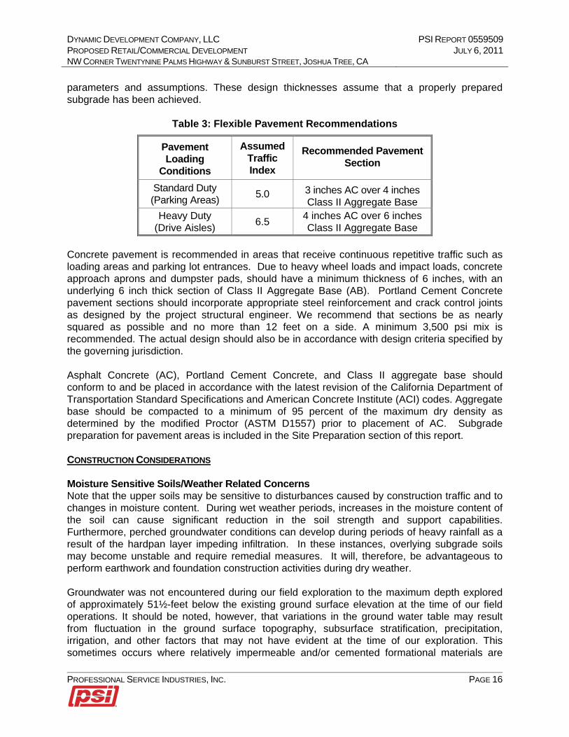
parameters and assumptions. These design thicknesses assume that a properly prepared subgrade has been achieved.
Table 3: Flexible Pavement Recommendations
Pavement Loading
Conditions
Assumed Traffic Index
Recommended Pavement Section
Standard Duty (Parking Areas)
5.0 3 inches AC over 4 inches Class II Aggregate Base
Heavy Duty (Drive Aisles)
6.5 4 inches AC over 6 inches Class II Aggregate Base
Concrete pavement is recommended in areas that receive continuous repetitive traffic such as loading areas and parking lot entrances. Due to heavy wheel loads and impact loads, concrete approach aprons and dumpster pads, should have a minimum thickness of 6 inches, with an underlying 6 inch thick section of Class II Aggregate Base (AB). Portland Cement Concrete pavement sections should incorporate appropriate steel reinforcement and crack control joints as designed by the project structural engineer. We recommend that sections be as nearly squared as possible and no more than 12 feet on a side. A minimum 3,500 psi mix is recommended. The actual design should also be in accordance with design criteria specified by the governing jurisdiction. Asphalt Concrete (AC), Portland Cement Concrete, and Class II aggregate base should conform to and be placed in accordance with the latest revision of the California Department of Transportation Standard Specifications and American Concrete Institute (ACI) codes. Aggregate base should be compacted to a minimum of 95 percent of the maximum dry density as determined by the modified Proctor (ASTM D1557) prior to placement of AC. Subgrade preparation for pavement areas is included in the Site Preparation section of this report. CONSTRUCTION CONSIDERATIONS Moisture Sensitive Soils/Weather Related Concerns Note that the upper soils may be sensitive to disturbances caused by construction traffic and to changes in moisture content. During wet weather periods, increases in the moisture content of the soil can cause significant reduction in the soil strength and support capabilities. Furthermore, perched groundwater conditions can develop during periods of heavy rainfall as a result of the hardpan layer impeding infiltration. In these instances, overlying subgrade soils may become unstable and require remedial measures. It will, therefore, be advantageous to perform earthwork and foundation construction activities during dry weather. Groundwater was not encountered during our field exploration to the maximum depth explored of approximately 51½-feet below the existing ground surface elevation at the time of our field operations. It should be noted, however, that variations in the ground water table may result from fluctuation in the ground surface topography, subsurface stratification, precipitation, irrigation, and other factors that may not have evident at the time of our exploration. This sometimes occurs where relatively impermeable and/or cemented formational materials are
DYNAMIC DEVELOPMENT COMPANY, LLC PSI REPORT 0559509 PROPOSED RETAIL/COMMERCIAL DEVELOPMENT JULY 6, 2011 NW CORNER TWENTYNINE PALMS HIGHWAY & SUNBURST STREET, JOSHUA TREE, CA
PROFESSIONAL SERVICE INDUSTRIES, INC. PAGE 17
overlain by fill soils. We recommend that a representative of PSI be present during grading operations to evaluate areas of seepage. Drainage devices for reduction of water accumulation can be recommended if these conditions occur. Water should not be allowed to collect in the foundation excavation, on floor slab areas, or on prepared subgrades of the construction area either during or after construction. Undercut or excavated areas should be sloped toward one corner to facilitate removal of any collected rainwater, groundwater, or surface runoff. Positive site drainage should be provided to reduce infiltration of surface water around the perimeter of the building and beneath the floor slabs. The grades should be sloped away from the building and surface drainage should be collected and discharged such that water is not permitted to infiltrate the backfill and floor slab areas of the building. PLAN REVIEW Once final design plans and specifications are available, a review of grading and foundation plans by PSI is recommended as a means to check that the evaluations made in preparation of this report are correct and that earthwork and foundation recommendations have been properly interpreted and implemented. OBSERVATION AND TESTING DURING CONSTRUCTION It is recommended that PSI be retained to provide observation and testing services during site preparation, site grading, utility trench construction, foundation excavation, and paving. This is to observe compliance with the design concepts, specifications and recommendations, and to allow for possible changes in the event that subsurface conditions differ from those anticipated prior to the start of construction.
REPORT LIMITATIONS The proposed professional services have been performed, findings obtained, and recommendations prepared in accordance with generally accepted geotechnical engineering principles and practices at the time of this report. PSI is not responsible for the conclusions, opinions, or recommendations made by others based on this data. No other warranties are implied or expressed. Dynamic Development Company, LLC, its subsidiaries and affiliates can rely upon the report under the same terms as if it was originally prepared for them. The scope of exploration was intended to evaluate soil conditions within the influence of the proposed foundations. The analyses and recommendations submitted in this report are based upon the data obtained from the soil borings performed at the locations indicated. If any subsoil variations become evident during the course of this project, a re-evaluation of the recommendations contained in this report will be necessary after we have had an opportunity to observe the characteristics of the conditions encountered. The applicability of the report should also be reviewed in the event significant changes occur in the design, nature, or location of the proposed structure.

DYNAMIC DEVELOPMENT COMPANY, LLC PSI REPORT 0559509 PROPOSED RETAIL/COMMERCIAL DEVELOPMENT JULY 6, 2011 NW CORNER TWENTYNINE PALMS HIGHWAY & SUNBURST STREET, JOSHUA TREE, CA
PROFESSIONAL SERVICE INDUSTRIES, INC. PAGE 18
APPENDIX

DATE:
5/19/2011
PROPOSED RETAIL/COMMERCIAL DEVELOPMENT
NWC TWENTYNINE PALMS HWY & SUNBURST STREET
JOSHUA TREE, CALIFORNIA
PSI PROJECT NUMBER: 0559509
PSI, INC. 6330 GATEWAY DRIVE, SUITE B
CYPRESS, CALIFORNIA
DRAWN BY: SM SITE VICINITY MAP
FIGURE 1
SUBJECT SITE

DATE: 06/21/2011
PROPOSED DOLLAR GENERAL STORE NWC TWENTY NINE PALMS HIGHWAY &
SUNBURST STREET, JOSHUA TREE SAN BERNARDINO COUNTY, CALIFORNIA
PSI PROJECT NUMBER: 0559509
PSI, INC. 6330 GATEWAY DRIVE, SUITE B
CYPRESS, CALIFORNIA
DRAWN BY: SM BORING LOCATION MAP FIGURE 2

1SW
SW
SW
SP
SW
3-5-5N=10
4-5-6N=11
7-9-10N=19
5-8-11N=19
Resist.=7600.0ohm-mpH = 6.5SO4 = 41.0 mg/KgDD = 114 pcf
18
18
18
18
SAND (SW), light brown, dry, fine to coarsegrained sand.SAND (SW), light brown, dry, loose, fine tocoarse grained sand.
SAND (SW), light brown, damp, loose, fineto coarse grained sand.
SAND (SP), light brown, slightly moist,medium dense, very fine to medium grainedsand.
SAND (SW), light brown, slightly moist,medium dense, fine to coarse grained sand.
Total Depth: Approximately 10-feet belowexisting grade.Groundwater was not encountered to themaximum depth explored.Boring was backfilled with soil cuttings uponcompletion.
PL
Ele
vatio
n (f
eet)
LL
4.0
25
Rec
over
y (in
ches
)Station: N/AOffset: N/A
The stratification lines represent approximate boundaries. The transition may be gradual.
De
pth
, (fe
et)
Sample Types:
STRENGTH, tsf
0559509Proposed Retail/Commercial DevelopmentNWC Twentynine Palms Highway & Sunburst St.Joshua Tree
AdditionalRemarks
US
CS
Cla
ssifi
catio
n
Boring Location:
0
Qp
Sheet 1 of 1
0
5
10
Professional Service Industries, Inc.6330 Gateway Drive, Suite BCypress, CA 90630Telephone: (714) 484-8600Fax: (714) 484-8601
Sa
mp
le T
ype
2.0
Drilling Method:Sampling Method:Hammer Type:
0
WATER LEVELS
Moi
stur
e, %
MoistureMATERIAL DESCRIPTION
STANDARD PENETRATIONTEST DATA
N in blows/ft
PSI Job No.:Project:Location:
Latitude: 34.1354N°Longitude: -116.3091W°Drill Rig:Remarks:
Shelby Tube
Hand Auger
Calif. Sampler
Texas Cone
SP
T B
low
s pe
r 6-
inch
(S
S)
Qu
Auger Cutting
Split-Spoon
Rock Core
Proposed Parking Area
Sam
ple
No.
Gra
phic
Log
LOG OF BORING B1
50
Completion Depth:Date Boring Started:Date Boring Completed:Logged By:Drilling Contractor:
10.0 ft6/20/116/20/11L. GussCal Pac Drilling
Hollow Stem Auger SSAutomatic

2
1
SW
SW
SW
SM
SW
SW
SW
SW
4-6-6N=12
5-7-9N=16
7-8-9N=17
4-9-13N=22
4-6-8N=14
7-11-15N=26
6-9-10N=19
6-9-12N=21
DD = 113 pcf
DD = 113 pcf
18
18
18
18
18
18
18
18
SAND (SW), light brown, dry, fine to coarsegrained sand.SAND (SW), light brown, dry, loose, fine tocoarse grained sand.
SAND (SW), light brown, dry, mediumdense, very fine to medium grained sand,some coarse grained sand.
Silty SAND (SM), light brown, dry, mediumdense, with some pebbles.
SAND (SW), light brown, damp, mediumdense, very fine to coarse grained sand,some gravel.
SAND (SW), light brown, slightly moist,medium dense, very fine to coarse grainedsand, some gravel.
SAND (SW), light brown, slightly moist,dense, very fine to coarse grained sand,some gravel.
SAND (SW), light brown, slightly moist,medium dense, very fine to coarse grainedsand, some gravel.
PL
Ele
vatio
n (f
eet)
LL
4.0
Continued Next Page
25
Rec
over
y (in
ches
)Station: N/AOffset: N/A
The stratification lines represent approximate boundaries. The transition may be gradual.
De
pth
, (fe
et)
Sample Types:
STRENGTH, tsf
0559509Proposed Retail/Commercial DevelopmentNWC Twentynine Palms Highway & Sunburst St.Joshua Tree
AdditionalRemarks
US
CS
Cla
ssifi
catio
n
Boring Location:
0
Qp
Sheet 1 of 2
0
5
10
15
20
25
30
Professional Service Industries, Inc.6330 Gateway Drive, Suite BCypress, CA 90630Telephone: (714) 484-8600Fax: (714) 484-8601
Sa
mp
le T
ype
2.0
Drilling Method:Sampling Method:Hammer Type:
0
WATER LEVELS
Moi
stur
e, %
MoistureMATERIAL DESCRIPTION
STANDARD PENETRATIONTEST DATA
N in blows/ft
PSI Job No.:Project:Location:
Latitude: 34.1354N°Longitude: -116.3091W°Drill Rig:Remarks:
Shelby Tube
Hand Auger
Calif. Sampler
Texas Cone
SP
T B
low
s pe
r 6-
inch
(S
S)
Qu
Auger Cutting
Split-Spoon
Rock Core
Proposed Building Pad
Sam
ple
No.
Gra
phic
Log
LOG OF BORING B2
50
Completion Depth:Date Boring Started:Date Boring Completed:Logged By:Drilling Contractor:
50.0 ft6/20/116/20/11L. GussCal Pac Drilling
Hollow Stem Auger SSAutomatic

SM
SW
SW
SW
SM
6-11-16N=27
8-11-15N=26
8-14-16N=30
8-13-4N=17
18
18
18
18
Silty SAND (SM), light brown, slightly moist,medium dense, very fine to medium grainedsand.
SAND (SW), light brown, slightly moist,medium dense, fine to coarse grained sand,some gravel.
SAND (SW), light brown, slightly moist,medium dense, fine to coarse grained sand,some gravel.
SAND (SW), light brown, slightly moist,dense, fine to coarse grained sand, slightincrease in gravel content.
Silty SAND (SM), light brown, slightly moist,medium dense, some gravel.
Total Depth: Approximately 50-feet belowexisting grade.Groundwater was not encountered to themaximum depth explored.Boring was backfilled with soil cuttings uponcompletion.
PL
Ele
vatio
n (f
eet)
LL
4.0
25
Rec
over
y (in
ches
)Station: N/AOffset: N/A
The stratification lines represent approximate boundaries. The transition may be gradual.
De
pth
, (fe
et)
Sample Types:
STRENGTH, tsf
0559509Proposed Retail/Commercial DevelopmentNWC Twentynine Palms Highway & Sunburst St.Joshua Tree
AdditionalRemarks
US
CS
Cla
ssifi
catio
n
Boring Location:
0
Qp
Sheet 2 of 2
30
35
40
45
50
Professional Service Industries, Inc.6330 Gateway Drive, Suite BCypress, CA 90630Telephone: (714) 484-8600Fax: (714) 484-8601
Sa
mp
le T
ype
2.0
Drilling Method:Sampling Method:Hammer Type:
0
WATER LEVELS
Moi
stur
e, %
MoistureMATERIAL DESCRIPTION
STANDARD PENETRATIONTEST DATA
N in blows/ft
PSI Job No.:Project:Location:
Latitude: 34.1354N°Longitude: -116.3091W°Drill Rig:Remarks:
Shelby Tube
Hand Auger
Calif. Sampler
Texas Cone
SP
T B
low
s pe
r 6-
inch
(S
S)
Qu
Auger Cutting
Split-Spoon
Rock Core
Proposed Building Pad
Sam
ple
No.
Gra
phic
Log
LOG OF BORING B2
50
Completion Depth:Date Boring Started:Date Boring Completed:Logged By:Drilling Contractor:
50.0 ft6/20/116/20/11L. GussCal Pac Drilling
Hollow Stem Auger SSAutomatic

1
SW
SW
SM
SW
SW
SW
SW
5-7-7N=14
4-7-8N=15
4-6-7N=13
5-7-9N=16
6-6-4N=10
6-7-12N=19
18
18
18
18
18
18
SAND (SW), light brown, dry, very fine tocoarse grained sand.SAND (SW), light brown, damp, loose, veryfine to coarse grained sand.
Silty SAND (SM), light brown, damp, loose.
SAND (SW), light brown, dry, loose.
SAND (SW), light brown, damp, mediumdense, very fine to coarse grained sand,some gravel.
SAND (SW), light brown, slightly moist,medium dense, very fine to coarse grainedsand, some gravel.
SAND (SW), light brown, slightly moist,medium dense, very fine to coarse grainedsand, some gravel.
Total Depth: Approximately 20-feet belowexisting grade.Groundwater was not encountered to themaximum depth explored.Boring was backfilled with soil cuttings uponcompletion.
PL
Ele
vatio
n (f
eet)
LL
4.0
25
Rec
over
y (in
ches
)Station: N/AOffset: N/A
The stratification lines represent approximate boundaries. The transition may be gradual.
De
pth
, (fe
et)
Sample Types:
STRENGTH, tsf
0559509Proposed Retail/Commercial DevelopmentNWC Twentynine Palms Highway & Sunburst St.Joshua Tree
AdditionalRemarks
US
CS
Cla
ssifi
catio
n
Boring Location:
0
Qp
Sheet 1 of 1
0
5
10
15
20
Professional Service Industries, Inc.6330 Gateway Drive, Suite BCypress, CA 90630Telephone: (714) 484-8600Fax: (714) 484-8601
Sa
mp
le T
ype
2.0
Drilling Method:Sampling Method:Hammer Type:
0
WATER LEVELS
Moi
stur
e, %
MoistureMATERIAL DESCRIPTION
STANDARD PENETRATIONTEST DATA
N in blows/ft
PSI Job No.:Project:Location:
Latitude: 34.1354N°Longitude: -116.3091W°Drill Rig:Remarks:
Shelby Tube
Hand Auger
Calif. Sampler
Texas Cone
SP
T B
low
s pe
r 6-
inch
(S
S)
Qu
Auger Cutting
Split-Spoon
Rock Core
Proposed Building Pad
Sam
ple
No.
Gra
phic
Log
LOG OF BORING B3
50
Completion Depth:Date Boring Started:Date Boring Completed:Logged By:Drilling Contractor:
20.0 ft6/20/116/20/11L. GussCal Pac Drilling
Hollow Stem Auger SSAutomatic

3
3
SW
SW
SM
SW
SW
SW
SW
5-6-7N=13
9-7-9N=16
5-10-12N=22
5-8-10N=18
3-8-12N=20
5-7-7N=14
DD = 113 pcf
DD = 114 pcf
18
18
18
18
18
18
SAND (SW), light brown, damp, fine tocoarse grained sand.SAND (SW), light brown, damp, loose, fineto coarse grained sand.
Silty SAND (SM), light brown, damp,medium dense.
SAND (SW), light brown, damp, mediumdense, fine to coarse grained sand.
SAND (SW), light brown, damp, mediumdense, fine to coarse grained sand.
SAND (SW), light brown, slightly moist,medium dense.
SAND (SW), light brown, slightly moist,medium dense, very fine to coarse grainedsand, trace silt.
Total Depth: Approximately 20-feet belowexisting grade.Groundwater was not encountered to themaximum depth explored.Boring was backfilled with soil cuttings uponcompletion.
PL
Ele
vatio
n (f
eet)
LL
4.0
25
Rec
over
y (in
ches
)Station: N/AOffset: N/A
The stratification lines represent approximate boundaries. The transition may be gradual.
De
pth
, (fe
et)
Sample Types:
STRENGTH, tsf
0559509Proposed Retail/Commercial DevelopmentNWC Twentynine Palms Highway & Sunburst St.Joshua Tree
AdditionalRemarks
US
CS
Cla
ssifi
catio
n
Boring Location:
0
Qp
Sheet 1 of 1
0
5
10
15
20
Professional Service Industries, Inc.6330 Gateway Drive, Suite BCypress, CA 90630Telephone: (714) 484-8600Fax: (714) 484-8601
Sa
mp
le T
ype
2.0
Drilling Method:Sampling Method:Hammer Type:
0
WATER LEVELS
Moi
stur
e, %
MoistureMATERIAL DESCRIPTION
STANDARD PENETRATIONTEST DATA
N in blows/ft
PSI Job No.:Project:Location:
Latitude: 34.1354N°Longitude: -116.3091W°Drill Rig:Remarks:
Shelby Tube
Hand Auger
Calif. Sampler
Texas Cone
SP
T B
low
s pe
r 6-
inch
(S
S)
Qu
Auger Cutting
Split-Spoon
Rock Core
Proposed Building Pad
Sam
ple
No.
Gra
phic
Log
LOG OF BORING B4
50
Completion Depth:Date Boring Started:Date Boring Completed:Logged By:Drilling Contractor:
20.0 ft6/20/116/20/11L. GussCal Pac Drilling
Hollow Stem Auger SSAutomatic

2
SW
SW
SM
SW
SW
SW
SW
4-6-7N=13
3-5-5N=10
4-4-8N=12
5-7-9N=16
3-5-6N=11
7-7-10N=17
DD = 109 pcf
18
18
18
18
18
18
SAND (SW), light brown, damp, fine tocoarse grained sand.SAND (SW), light brown, damp, loose, fineto coarse grained sand.
Silty SAND (SM), light brown, damp, loose.
SAND (SW), light brown, dry, loose, fine tocoarse grained sand.
SAND (SW), light brown, damp, mediumdense, fine to coarse grained sand.
SAND (SW), light brown, slightly moist,medium dense, fine to coarse grained sand,trace gravel.
SAND (SW), light brown, slightly moist,medium dense, fine to coarse grained sand,trace gravel.
Total Depth: Approximately 20-feet belowexisting grade.Groundwater was not encountered to themaximum depth explored.Boring was backfilled with soil cuttings uponcompletion.
PL
Ele
vatio
n (f
eet)
LL
4.0
25
Rec
over
y (in
ches
)Station: N/AOffset: N/A
The stratification lines represent approximate boundaries. The transition may be gradual.
De
pth
, (fe
et)
Sample Types:
STRENGTH, tsf
0559509Proposed Retail/Commercial DevelopmentNWC Twentynine Palms Highway & Sunburst St.Joshua Tree
AdditionalRemarks
US
CS
Cla
ssifi
catio
n
Boring Location:
0
Qp
Sheet 1 of 1
0
5
10
15
20
Professional Service Industries, Inc.6330 Gateway Drive, Suite BCypress, CA 90630Telephone: (714) 484-8600Fax: (714) 484-8601
Sa
mp
le T
ype
2.0
Drilling Method:Sampling Method:Hammer Type:
0
WATER LEVELS
Moi
stur
e, %
MoistureMATERIAL DESCRIPTION
STANDARD PENETRATIONTEST DATA
N in blows/ft
PSI Job No.:Project:Location:
Latitude: 34.1354N°Longitude: -116.3091W°Drill Rig:Remarks:
Shelby Tube
Hand Auger
Calif. Sampler
Texas Cone
SP
T B
low
s pe
r 6-
inch
(S
S)
Qu
Auger Cutting
Split-Spoon
Rock Core
Proposed Building Pad
Sam
ple
No.
Gra
phic
Log
LOG OF BORING B5
50
Completion Depth:Date Boring Started:Date Boring Completed:Logged By:Drilling Contractor:
20.0 ft6/20/116/20/11L. GussCal Pac Drilling
Hollow Stem Auger SSAutomatic

SM
SM
SM
SW
SW
4-5-6N=11
4-6-6N=12
4-7-10N=17
5-7-9N=16
18
18
18
18
Silty SAND (SM), light brown, damp, finegrained sand.Silty SAND (SM), light brown, damp, loose,fine to medium grained sand..
Silty SAND (SM), light brown, damp, loose.
SAND (SW), light brown, slightly moist,loose, fine to coarse grained sand, tracegravel.
SAND (SW), light brown, slightly moist,loose, fine to coarse grained sand, tracegravel.
Total Depth: Approximately 10-feet belowexisting grade.Groundwater was not encountered to themaximum depth explored.Boring was backfilled with soil cuttings uponcompletion.
PL
Ele
vatio
n (f
eet)
LL
4.0
25
Rec
over
y (in
ches
)Station: N/AOffset: N/A
The stratification lines represent approximate boundaries. The transition may be gradual.
De
pth
, (fe
et)
Sample Types:
STRENGTH, tsf
0559509Proposed Retail/Commercial DevelopmentNWC Twentynine Palms Highway & Sunburst St.Joshua Tree
AdditionalRemarks
US
CS
Cla
ssifi
catio
n
Boring Location:
0
Qp
Sheet 1 of 1
0
5
10
Professional Service Industries, Inc.6330 Gateway Drive, Suite BCypress, CA 90630Telephone: (714) 484-8600Fax: (714) 484-8601
Sa
mp
le T
ype
2.0
Drilling Method:Sampling Method:Hammer Type:
0
WATER LEVELS
Moi
stur
e, %
MoistureMATERIAL DESCRIPTION
STANDARD PENETRATIONTEST DATA
N in blows/ft
PSI Job No.:Project:Location:
Latitude: 34.1354N°Longitude: -116.3091W°Drill Rig:Remarks:
Shelby Tube
Hand Auger
Calif. Sampler
Texas Cone
SP
T B
low
s pe
r 6-
inch
(S
S)
Qu
Auger Cutting
Split-Spoon
Rock Core
Proposed Parking Area
Sam
ple
No.
Gra
phic
Log
LOG OF BORING B6
50
Completion Depth:Date Boring Started:Date Boring Completed:Logged By:Drilling Contractor:
10.0 ft6/20/116/20/11L. GussCal Pac Drilling
Hollow Stem Auger SSAutomatic

2SW
SW
SM
SW
SW
4-6-7N=13
4-6-8N=14
4-5-7N=12
9-9-12N=21
DD = 113 pcf
18
18
18
18
SAND (SW), light brown, damp, fine tocoarse grained sand.SAND (SW), light brown, dry, loose, fine tocoarse grained sand.
Silty SAND (SM), light brown, dry, loose.
SAND (SW), light brown, slightly moist,loose, fine to coarse grained sand.
Sandy SILT / Silty SAND (ML/SM), lightbrown, moist, stiff/medium dense.
Total Depth: Approximately 10-feet belowexisting grade.Groundwater was not encountered to themaximum depth explored.Boring was backfilled with soil cuttings uponcompletion.
PL
Ele
vatio
n (f
eet)
LL
4.0
25
Rec
over
y (in
ches
)Station: N/AOffset: N/A
The stratification lines represent approximate boundaries. The transition may be gradual.
De
pth
, (fe
et)
Sample Types:
STRENGTH, tsf
0559509Proposed Retail/Commercial DevelopmentNWC Twentynine Palms Highway & Sunburst St.Joshua Tree
AdditionalRemarks
US
CS
Cla
ssifi
catio
n
Boring Location:
0
Qp
Sheet 1 of 1
0
5
10
Professional Service Industries, Inc.6330 Gateway Drive, Suite BCypress, CA 90630Telephone: (714) 484-8600Fax: (714) 484-8601
Sa
mp
le T
ype
2.0
Drilling Method:Sampling Method:Hammer Type:
0
WATER LEVELS
Moi
stur
e, %
MoistureMATERIAL DESCRIPTION
STANDARD PENETRATIONTEST DATA
N in blows/ft
PSI Job No.:Project:Location:
Latitude: 34.1354N°Longitude: -116.3091W°Drill Rig:Remarks:
Shelby Tube
Hand Auger
Calif. Sampler
Texas Cone
SP
T B
low
s pe
r 6-
inch
(S
S)
Qu
Auger Cutting
Split-Spoon
Rock Core
Proposed Parking Area
Sam
ple
No.
Gra
phic
Log
LOG OF BORING B7
50
Completion Depth:Date Boring Started:Date Boring Completed:Logged By:Drilling Contractor:
10.0 ft6/20/116/20/11L. GussCal Pac Drilling
Hollow Stem Auger SSAutomatic

2
SW
SW
SW
SW
SM
4-6-9N=15
5-7-9N=16
5-5-7N=12
4-7-10N=17
DD = 108 pcf
18
18
18
18
SAND (SW), light brown, dry, fine to coarsegrained sand.SAND (SW), light brown, dry, loose, fine tocoarse grained sand, trace gravel.
SAND (SW), light brown, dry, mediumdense, fine to coarse grained sand, tracegravel.
SAND (SW), light brown, damp, oose, fine tocoarse grained sand, trace gravel and silt.
Silty SAND (SM), light brown, slightly moist,meium dense.
Total Depth: Approximately 10-feet belowexisting grade.Groundwater was not encountered to themaximum depth explored.Boring was backfilled with soil cuttings uponcompletion.
PL
Ele
vatio
n (f
eet)
LL
4.0
25
Rec
over
y (in
ches
)Station: N/AOffset: N/A
The stratification lines represent approximate boundaries. The transition may be gradual.
De
pth
, (fe
et)
Sample Types:
STRENGTH, tsf
0559509Proposed Retail/Commercial DevelopmentNWC Twentynine Palms Highway & Sunburst St.Joshua Tree
AdditionalRemarks
US
CS
Cla
ssifi
catio
n
Boring Location:
0
Qp
Sheet 1 of 1
0
5
10
Professional Service Industries, Inc.6330 Gateway Drive, Suite BCypress, CA 90630Telephone: (714) 484-8600Fax: (714) 484-8601
Sa
mp
le T
ype
2.0
Drilling Method:Sampling Method:Hammer Type:
0
WATER LEVELS
Moi
stur
e, %
MoistureMATERIAL DESCRIPTION
STANDARD PENETRATIONTEST DATA
N in blows/ft
PSI Job No.:Project:Location:
Latitude: 34.1354N°Longitude: -116.3091W°Drill Rig:Remarks:
Shelby Tube
Hand Auger
Calif. Sampler
Texas Cone
SP
T B
low
s pe
r 6-
inch
(S
S)
Qu
Auger Cutting
Split-Spoon
Rock Core
Proposed Parking Area
Sam
ple
No.
Gra
phic
Log
LOG OF BORING B8
50
Completion Depth:Date Boring Started:Date Boring Completed:Logged By:Drilling Contractor:
10.0 ft6/20/116/20/11L. GussCal Pac Drilling
Hollow Stem Auger SSAutomatic


0559497DATE: 6/22/2011
DEPTH % COARSE % FINES CLASSIFICATION13-1/2 Ft 95.0% 5.0% SAND (SW)28-1/2 Ft 89.1% 10.9% Silty SAND (SM)B2
Proposed Retail/Commercial Development - Joshua Tree
SIEVE ANALYSIS
BORING NO.B2
RESULTS:
PROJECT: PROJECT NO.:

PSI # 0559509CONSOLIDATION TEST - ASTM D2435
Job No. 2008-026
Boring / Sample No. B3 Depth: 3.5' Date 06-22-11
0.999
0.9890
0.9879
0.80
0.81
0.82
0.83
0.84
0.85
0.86
0.87
0.88
0.89
0.90
0.91
0.92
0.93
0.94
0.95
0.96
0.97
0.98
0.99
1.00
100 1000 10000 100000
Sam
ple
Heig
ht
(inches)
Vertical Pressure (psf)
F.M. Silty SandDry Density: 115.1 pcf
Initial Water Content: 4.0 %Final Water Content: 15.4 %
H2O @ 2000 PSF
.Natural
o Submerged
GeoLogic Associates

PSI # 0559509CONSOLIDATION TEST - ASTM D2435
Job No. 2008-026
Boring / Sample No. B5 Depth: 3.5' Date 06-22-11
0.9987
0.9886
0.9861
0.80
0.81
0.82
0.83
0.84
0.85
0.86
0.87
0.88
0.89
0.90
0.91
0.92
0.93
0.94
0.95
0.96
0.97
0.98
0.99
1.00
100 1000 10000 100000
Sam
ple
Heig
ht
(inches)
Vertical Pressure (psf)
F.C. Silty SandDry Density: 115.1 pcf
Initial Water Content: 2.7 %Final Water Content: 13.6 %
H2O @ 2000 PSF
.Natural
o Submerged
GeoLogic Associates

PSI # 0559509 SOIL TEST RESULTS Job No. 2008-026
SAMPLE NO.: B-2 @ 0-5' `
DESCRIPTION F.C. Silty Sand
DIRECT SHEAR TEST (type)
Initial Moisture Content %
Dry Density (pcf)
Normal Stress (psf)
Peak Shear Stress (psf)
Ultimate Shear Stress (psf)
Cohesion (psf)
Internal Friction Angle (degrees)
EXPANSION TEST UBC STD 18-2
Initial Dry Density (pcf)
Initial Moisture Content %
Final Moisture Content %
Pressure (psf)
Expansion Index Swell %
CORROSIVITY TEST
Resistivity (CTM643) (ohm-cm) 17000
pH (CTM643) 6.7
CHEMICAL TESTS
Soluble Sulfate (CTM 417) (ppm) 66
Chloride Content (CTM 422) (ppm) 89
Wash #200 Sieve (ASTM-1140) %
Sand Equivalent (ASTM D2419)
GeoLogic Associates

Standard Guidelines For Grading Projects
STANDARD GUIDELINES FOR GRADING PROJECTS
Presented By:
Professional Service Industries, Inc.

Standard Guidelines For Grading Projects
TABLE OF CONTENT
GENERAL ..............................................................................................................................................SG-1 DEFINITION OF TERMS .......................................................................................................................... 1 OBLIGATIONS OF PARTIES................................................................................................................... 5 SITE PREPARATION................................................................................................................................. 5 SITE PROTECTION ................................................................................................................................... 6 EXCAVATIONS .......................................................................................................................................... 7
Unsuitable Materials ................................................................................................................................ 7 Cut Slopes.................................................................................................................................................. 7 Pad Areas .................................................................................................................................................. 8
COMPACTED FILL.................................................................................................................................... 8
Placement .................................................................................................................................................. 8 Moisture .................................................................................................................................................. 10 Fill Material ............................................................................................................................................ 10 Fill Slopes ................................................................................................................................................ 12 Off-Site Fill.............................................................................................................................................. 13
DRAINAGE ................................................................................................................................................ 13 STAKING ................................................................................................................................................... 14 SLOPE MAINTENANCE ......................................................................................................................... 14
Landscape Plants .................................................................................................................................... 14 Irrigation ................................................................................................................................................. 14 Maintenance............................................................................................................................................ 15 Repairs..................................................................................................................................................... 15
TRENCH BACKFILL ............................................................................................................................... 15 STATUS OF GRADING............................................................................................................................ 16

Standard Guidelines For Grading Projects
SG - 1
GENERAL The guidelines contained herein and the standard details attached hereto represent this firm’s standard recommendation for grading and other associated operations on construction projects. These guidelines should be considered a portion of the project specifications. All plates attached hereto shall be considered as part of these guidelines. The Contractor should not vary from these guidelines without prior recommendation by the Geotechnical Consultant and the approval of the Client or his authorized representative. Recommendation by the Geotechnical Consultant and/or Client should not be considered to preclude requirements for the approval by the controlling agency prior to the execution of any changes. These Standard Grading Guidelines and Standard Details may be modified and/or superseded by recommendations contained in the text of the preliminary Geotechnical Report and/or subsequent reports. If disputes arise out of the interpretation of these grading guidelines or standard details, the Geotechnical Consultant shall provide the governing interpretation. DEFINITION OF TERMS ALLUVIUM – Unconsolidated soil deposits resulting from flow of water, including sediments deposited in river beds, canyons, flood plains, lakes, fans and estuaries. AS-GRADED (AS-BUILT) – The surface and subsurface conditions at completion of grading. BACKCUT – A temporary construction slope at the rear of earth retaining structures such as buttresses, shear keys, stabilization fills or retaining walls. BACKDRAIN – Generally a pipe and gravel or similar drainage system placed behind earth retaining structures such buttresses, stabilization fills, and retaining walls. BEDROCK – Relatively undisturbed formational rock, more or less solid, either at the surface or beneath superficial deposits of soil. BENCH – A relatively level step and near vertical rise excavated into sloping ground on which fill is to be placed. BORROW (Import) – Any fill material hauled to the project site from off-site areas.

Standard Guidelines For Grading Projects
SG - 2
BUTTRESS FILL – A fill mass, the configuration of which is designed by engineering calculations to retain slope conditions containing adverse geologic features. A buttress is generally specified by minimum key width and depth and by maximum backcut angle. A buttress normally contains a back-drainage system. CIVIL ENGINEER – The Registered Civil Engineer or consulting firm responsible for preparation of the grading plans, surveying and verifying as-graded topographic conditions. CLIENT – The Developer or his authorized representative who is chiefly in charge of the project. He shall have the responsibility of reviewing the findings and recommendations made by the Geotechnical Consultant and shall authorize the Contractor and/or other consultants to perform work and/or provide services. COLLUVIUM – Generally loose deposits usually found near the base of slopes and brought there chiefly by gravity through slow continuous downhill creep (also see Slope Wash). COMPACTION – Densification of man-placed fill by mechanical means. CONTRACTOR – A person or company under contract or otherwise retained by the Client to perform demolition, grading and other site improvements. DEBRIS – All products of clearing, grubbing, demolition, and contaminated soil materials unsuitable for reuse as compacted fill, and/or any other material so designated by the Geotechnical Consultant. ENGINEERING GEOLOGIST – A Geologist holding a valid certificate of registration in the specialty of Engineering Geology. ENGINEERED FILL – A fill of which the Geotechnical Consultant or his representative, during grading, has made sufficient tests to enable him to conclude that the fill has been placed in substantial compliance with the recommendations of the Geotechnical Consultant and the governing agency requirements. EROSION - The wearing away of ground surface as a result of the movement of wind, water, and/or ice. EXCAVATION – The mechanical removal of earth materials. EXISTING GRADE – The ground surface configuration prior to grading. FILL – Any deposits of soil, rock, soil-rock blends or other similar materials placed by man.

Standard Guidelines For Grading Projects
SG - 3
FINISH GRADE – The ground surface configuration at which time the surface elevations conform to the approved plan. GEOFABRIC – Any engineering textile utilized in geotechnical applications including subgrade stabilization and filtering. GEOLOGIST – A representative of the Geotechnical Consultant educated and trained in the field of geology. GEOTECHNICAL CONSULTANT – The Geotechnical Engineering and Engineering Geology consulting firm retained to provide technical services for the project. For the purpose of these specifications, observations by the Geotechnical Consultant include observations by the Soil Engineer, Geotechnical Engineer, Engineering Geologist and those performed by persons employed by and responsible to the Geotechnical Consultants. GEOTECHNICAL ENGINEER – A licensed Geotechnical Engineer or Civil Engineer who applies scientific methods, engineering principles and professional experience to the acquisition, interpretation and use of knowledge of materials of the earth’s crust for the evaluation of engineering problems. Geotechnical Engineering encompasses many of the engineering aspects of soil mechanics, rock mechanics, geology, geophysics, hydrology and related sciences. GRADING – Any operation consisting of excavation, filling or combinations thereof and associated operations. LANDSIDE DEBRIS – Material, generally porous and of low density, produced from instability of natural or man-made slopes. MAXIMUM DENSITY – Standard laboratory test for maximum dry unit weight. Unless otherwise specified, the maximum dry unity weight shall be determined in accordance with ASTM Method of Test D 1557-91. OPTIMUM MOISTURE – Soil moisture content at the test maximum density. RELATIVE COMPACTION – The degree of compaction (expressed as a percentage) of dry unit weight of a material as compared to the maximum dry unit weight of the material. ROUGH GRADE – The ground surface configuration at which time the surface elevations approximately conform to the approved plan. SITE - The particular parcel of land where grading is being performed.

Standard Guidelines For Grading Projects
SG - 4
SHEAR KEY – Similar to buttress, however, it is generally constructed by excavating a slot within a natural slope, in order to stabilize the upper portion of the slope without grading encroaching into the lower portion of the slope.
SLOPE – An inclined ground surface, the steepness of which is generally specified as a ration of horizontal:vertical (e.g., 2:1)
SLOPE WASH – Soil and/or rock material that has been transported down a slope by action of gravity assisted by runoff water not confined by channels (also see Colluvium).
SOIL – Naturally occurring deposits of sand, silt, clay, etc., or combinations thereof.
SOIL ENGINEER – Licensed Geotechnical Engineer or Civil Engineer experienced in soil mechanics (also see Geotechnical Engineer).
STABILIZATION FILL – A fill mass, the configuration of which is typically related to slope height and specified by the standards of practice for enhancing the stability of locally adverse conditions. A stabilization fill is normally specified by minimum key width and depth and by maximum backcut angle. A stabilization fill may or may not have a backdrainage system specified.
SUBDRAIN – Generally a pipe and gravel or similar drainage system placed beneath a fill in the alignment of canyons or formed drainage channels.
SLOUGH – Loose, non-compacted fill material generated during grading operations.
TAILINGS – Non-engineered fill which accumulates on or adjacent to equipment haul-roads.
TERRACE – Relatively level step constructed in the face of a graded slope surface for drainage control and maintenance purposes.
TOPSOIL – The presumable fertile upper zone of soil, which is usually darker in color and loose.
WINDROW – A string of large rocks buried within engineered fill in accordance with guidelines set forth by the Geotechnical Consultant.

Standard Guidelines For Grading Projects
SG - 5
OBLIGATIONS OF PARTIES
The Geotechnical Consultant should provide observation and testing services and should make evaluations in order to advise the Client on Geotechnical matters. The Geotechnical Consultant should report his findings and recommendations to the Client or his authorized representative. The client should be chiefly responsible for all aspects of the project. He or his authorized representative has the responsibility of reviewing the findings and recommendations of the Geotechnical Consultant. He shall authorize or cause to have authorized the Contractor and/or other consultants to perform work and/or provide services. During grading the Client or his authorized representative should remain on-site or should remain reasonably accessible to all concerned parties in order to make decisions necessary to maintain the flow of the project. The Contractor should be responsible for the safety of the project and satisfactory completion of all grading and other associated operations on construction projects, including but not limited to, earthwork in accordance with the project plans, specifications and controlling agency requirements. During grading, the Contractor or his authorized representative should remain on-site. Overnight and on days off, the Contractor should remain accessible. SITE PREPARATION
The Client, prior to any site preparation or grading, should arrange and attend a meeting among the Grading Contractor, the Design Engineer, the Geotechnical Consultant, representatives of the appropriate governing authorities as well as any other concerned parties. All parties should be given at least 48 hours notice. Clearing and grubbing should consist of the removal of vegetation such as brush, grass, woods, stumps, trees, roots of trees and otherwise deleterious natural materials from the areas to be graded. Clearing and grubbing should extend to the outside of all proposed excavation and fill areas. Demolition should include removal of buildings, structures, foundations, reservoirs, utilities (including underground pipelines, septic tanks, leach fields, seepage pits, cisterns, mining shafts, tunnels, etc.) and man-made surface and subsurface improvements from the areas to be graded. Demolition of utilities should include proper capping and/or re-routing pipelines at the project perimeter and cutoff and capping of wells in accordance with the requirements of the governing authorities and the recommendations of the Geotechnical Consultant at the time of the demolition. Trees, plants or man-made improvements not planned to be removed or demolished should be protected by the Contractor from damage or injury.

Standard Guidelines For Grading Projects
SG - 6
Debris generated during clearing, grubbing and/or demolition operations should be wasted from areas to be graded and disposed off-site. Clearing, grubbing and demolition operations should be performed under the observation of the Geotechnical Consultant. The Client or Contractor should obtain the required approvals for the controlling authorities for the project prior, during and/or after demolition, site preparation and removals, etc. The appropriate approvals should be obtained prior to proceeding with grading operations. SITE PROTECTION Protection of the site during the period of grading should be the responsibility of the Contractor. Unless other provisions are made in writing and agreed upon among the concerned parties, completion of a portion of the project should not be considered to preclude that portion or adjacent areas from the requirements for site protection until such time as the entire project is complete as identified by the Geotechnical Consultant, the Client and the regulating agencies. The Contractor should be responsible for the stability of all temporary excavations. Recommendations by the Geotechnical Consultant pertaining to temporary excavations (e.g., backcuts) are made in consideration of stability of the completed project and therefore, should not be considered to preclude the responsibilities of the Contractor. Recommendations by the Geotechnical Consultant should not be considered to preclude more restrictive requirements by the regulating agencies. Precautions should be taken during the performance of site clearing, excavations and grading to protect the work site from flooding, ponding, or inundation by poor or improper surface drainage. Temporary provisions should be made during the rainy season to adequately direct surface drainage away from and off the work site. Where low areas can not be avoided, pumps should be kept on hand to continually remove water during periods of rainfall. During periods of rainfall, plastic sheeting should be kept reasonably accessible to prevent unprotected slopes from becoming saturated. Where necessary during periods of rainfall, the Contractor should install check-dams de-silting basins, rip-rap, sandbags or other devices or methods necessary to control erosion and provide safe conditions. During periods of rainfall, the Geotechnical Consultant should be kept informed by the Contractor as to the nature of remedial or preventative work being performed (e.g., pumping, placement of sandbags or plastic sheeting, other labor, dozing, etc.). Following periods of rainfall, the Contractor should contact the Geotechnical Consultant and arrange a walk-over of the site in order to visually assess rain related damage. The Geotechnical Consultant may also recommend excavations and testing in order to aid in his assessments. At the request of the Geotechnical Consultant, the Contractor shall make excavations in order to evaluate the extent of rain related damage.

Standard Guidelines For Grading Projects
SG - 7
Rain-related damage should be considered to include, but may not be limited to, erosion, silting, saturation, swelling, structural distress and other adverse conditions identified by the Geotechnical Consultant. Soil adversely affected should be classified as Unsuitable Materials and should be subject to overexcavation and replaced with compacted fill or other remedial grading as recommended by the Geotechnical Consultant. Relatively level areas, where saturated soils and/or erosion gullies exist to depths greater then 1 foot, should be overexcavated to unaffected, competent material. Where less than 1 foot in depth, unsuitable materials may be processed in-place to achieve near optimum moisture conditions, then thoroughly recompacted in accordance with the applicable specifications. If the desired results are not achieved, the affected materials should be overexcavated then replaced in accordance with the applicable specifications. In slope areas, where saturated soil and/or erosion gullies exist to depths of greater than 1 foot, should be over-excavated to unaffected, competent material. Where affected materials exist to depths of 1 foot or less below proposed finished grade, remedial grading by moisture conditioning in-place, followed by thorough recompaction in accordance with the applicable grading guidelines herein may be attempted. If the desired results are not achieved, all affected materials should be overexcavated and replaced as compacted fill in accordance with the slope repair recommendations herein. As field conditions dictate, other slope repair procedures may be recommended by the Geotechnical Consultant. EXCAVATIONS
Unsuitable Materials Materials which are unsuitable should be excavated under observation and recommendations of the Geotechnical Consultant. Unsuitable materials include, but may not be limited to dry, loose, soft, wet, organic compressible natural soils and fractured, weathered, soft, bedrock and nonengineered or otherwise deleterious fill materials. Materials identified by the Geotechnical Consultant as unsatisfactory due to its moisture conditions should be overexcavated, watered or dried, as needed, and thoroughly blended to uniform near optimum moisture condition (per Moisture guidelines presented herein) prior to placement as compacted fill.
Cut Slopes Unless otherwise recommended by the Geotechnical Consultant and approved by the regulating agencies, permanent cut slopes should not be steeper than 2:1 (horizontal:vertical). If excavations for cut slopes expose loose, cohesionless, significantly fractured or otherwise suitable material, overexcavation and replacement of the unsuitable materials
Standard Guidelines For Grading Projects
SG - 8
with a compacted stabilization fill should be accomplished as recommended by the Geotechnical Consultant. Unless otherwise specified by the Geotechnical Consultant, stabilization fill construction should conform to the requirements of the Standard Details.
The Geotechnical Consultant should review cut slopes during excavation. The Geotechnical Consultant should be notified by the contractor prior to beginning slope excavations. If during the course of grading, adverse or potentially adverse geotechnical conditions are encountered which were not anticipated in the preliminary report, the Geotechnical Consultant should explore, analyze and make recommendations to treat these problems. When cuts slopes are made in the direction of the prevailing drainage, a non-erodible diversion swale (brow ditch) should be provided at the top-of-cut.
Pad Areas All lot pad areas, including side yard terraces, above stabilization fills or buttresses should be over-excavated to provide for a minimum of 3-feet (refer to Standard Details) of compacted fill over the entire pad area. Pad areas with both fill and cut materials exposed and pad areas containing both very shallow (less than 3-feet) and deeper fill should be over- thickness (refer to Standard Details). Cut areas exposing significantly varying material types should also be overexcavated to provide for at least a 3-foot thick compacted fill blanket. Geotechnical conditions may require greater depth of overexcavation. The actual depth should be delineated by the Geotechnical Consultant during grading. For pad areas created above cut or natural slopes, positive drainage should be established away from the top-of-slope. This may be accomplished utilizing a berm and/or an appropriate pad gradient. A gradient in soil areas away from the top-of-slope of 2 percent or greater is recommended. COMPACTED FILL All fill materials should be compacted as specified below or by other methods specifically recommended by the Geotechnical Consultant. Unless otherwise specified, the minimum degree of compaction (relative compaction) should be 90 percent of the laboratory maximum density.
Placement Prior to placement of compacted fill, the Contractor should request a review by the Geotechnical Consultant of the exposed ground surface. Unless otherwise recommended, the exposed ground surface should then be scarified (6-inches minimum), watered or dried as needed, thoroughly blended to achieve near optimum moisture

Standard Guidelines For Grading Projects
SG - 9
conditions, then thoroughly compacted to a minimum of 90 percent of the maximum density. The review by the Geotechnical Consultants should not be considered to preclude requirements of inspection and approval by the governing agency.
Compacted fill should be placed in thin horizontal lifts not exceeding 8-inches in loose thickness prior to compaction. Each lift should be watered or dried as needed, thoroughly blended to achieve near optimum moisture conditions then thoroughly compacted by mechanical methods to a minimum of 90 percent of laboratory maximum dry density. Each lift should be treated in a like manner until the desired finished grades are achieved.
The Contractor should have suitable and sufficient mechanical compaction equipment and watering apparatus on the job site to handle the amount of fill being placed in consideration of moisture retention properties of the materials. If necessary, excavation equipment should be “shut down” temporarily in order to permit proper compaction of fills. Earth moving equipment should only be considered a supplement and not substituted for conventional compaction equipment.
When placing fill in horizontal lifts adjacent to areas sloping steeper than 5:1 (horizontal:vertical), horizontal keys and vertical benches should be excavated into the adjacent slope area. Keying and benching should be sufficient to provide at least 6-foot wide benches and minimum of 4-feet of vertical bench height within the firm natural ground, firm bedrock or engineered compacted fill. No compacted fill should be placed in an area subsequent to keying and benching until the area has been reviewed by the Geotechnical Consultant. Material generated by the benching operation should be moved sufficiently away from the bench area to allow for the recommended review of the horizontal bench prior to placement of fill. Typical keying and benching details have been included within the accompanying Standard Details.
Within a single fill area where grading procedures dictate two or more separate fills, temporary slopes (false slopes) may be created. When placing fill adjacent to a false slope, benching should be conducted in the same manner as above described. At least a 3-foot vertical bench should be established within the firm core of adjacent approved compacted fill prior to placement of additional fill. Benching should proceed in at least 3-foot vertical increments until the desired finished grades are achieved.
Fill should be tested for compliance with the recommended relative compaction and moisture conditions. Field density testing should conform to ASTM Method of Testing D 1556-64, D 2922-78 and/or D2937-71. Tests should be provided for about every 2 vertical feet or 1,000 cubic yards of fill placed. Actual test intervals may vary as field conditions dictate. Fill found not to be in conformance with the grading recommendations should be removed or otherwise handled as recommended by the Geotechnical Consultant.

Standard Guidelines For Grading Projects
SG - 10
The Contractor should assist the Geotechnical Consultant and/or his representative by digging test pits for removal determinations and/or for testing compacted fill.
As recommended by the Geotechnical Consultant, the Contractor should “shutdown” or remove any grading equipment from an area being tested. The Geotechnical Consultant should maintain a plan with estimated locations of field tests. Unless the client provides for actual surveying of test locations, by the Geotechnical Consultant should only be considered rough estimates and should not be utilized for the purpose of preparing cross sections showing test locations or in any case for the purpose of after-the-fact evaluating of the sequence of fill placement.
Moisture For field testing purposes, “near optimum” moisture will vary with material type and other factors including compaction procedures. “Near optimum” may be specifically recommended in Preliminary Investigation Reports and/or may be evaluated during grading. Prior to placement of additional compacted fill following an overnight or other grading delay, the exposed surface of previously compacted fill should be processed by scarification, watered or dried as needed, thoroughly blended to near-optimum moisture conditions, then recompacted to a minimum of 90 percent of laboratory maximum dry density. Where wet or other dry or other unsuitable materials exist to depths of greater than one foot, the unsuitable materials should be overexcavated. Following a period of flooding, rainfall or overwatering by other means, no additional fill should be placed until damage assessments have been made and remedial grading performed as described herein.
Fill Material Excavated on-site materials which are acceptable to the Geotechnical Consultant may be utilized as compacted fill, provided trash, vegetation and other deleterious materials are removed prior to placement. Where import materials are required for use on-site, the Geotechnical Consultant should be notified at least 72 hours in advance of importing, in order to sample and test materials from proposed borrow sites. No import materials should be delivered for use on-site without prior sampling and testing by Geotechnical Consultant. Where oversized rock or similar irreducible material is generated during grading, it is recommended, where practical, to waste such material off-site or on-site in areas designated as “nonstructural rock disposal areas”. Rock placed in disposal areas should be placed with sufficient fines to fill voids. The rock should be compacted in lifts to an

Standard Guidelines For Grading Projects
SG - 11
unyielding condition. The disposal area should be covered with at least 3-feet of compacted fill, which is free of oversized material. The upper 3-feet should be placed in accordance with the guidelines for compacted fill herein.
Rocks 3 inches in maximum dimension and smaller may be utilized within the compacted fill, provided they are placed in such a manner that nesting of the rock in avoided. Fill should be placed and thoroughly compacted over and around all rock. The amount of rock should not exceed 40 percent by dry weight passing the ¾-inch sieve size. The 3-inch and 40 percent recommendations herein may vary as field conditions dictate. During the course of grading operations, rocks or similar irreducible materials greater than 3-inch maximum dimension (oversized material) may be generated. These rocks should not be placed within the compacted fill unless placed as recommended by the Geotechnical Consultant. Where rocks or similar irreducible materials of greater that 3-inches but less than 4-feet of maximum dimension are generated during grading, or otherwise desired to be placed within an engineered fill, special handling in accordance with the accompanying Standard Details is recommended. Rocks greater than 4 feet should be broken down or disposed off-site. Rocks up to 4-feet maximum dimension should be placed below the upper 10-feet of any fill and should not be closer than 20-feet to any slope face. These recommendations could vary as locations of improvements dictate. Where practical, oversized material should not be placed below areas where structures of deep utilities are proposes. Oversized material should be placed in windrows on a clean, overexcavated or unyielding compacted fill or firm natural ground surface. Select native or imported granular soil (S.E. 30 or higher) should be placed and thoroughly flooded over and around all windrowed rock, such that voids are filled. Windrows of oversized material should be staggered so that successive strata of oversized material are not in the same vertical plane. It may be possible to dispose of individual larger rock as field conditions dictate and as recommended by the Geotechnical Consultant at time of placement. Material that is considered unsuitable by the Geotechnical Consultant should not be utilized in the compacted fill. During grading operations, placing and mixing the materials from the cut and/or borrow areas may result in soil mixtures which possess unique physical properties. Testing may be required of samples obtained directly from the fill areas in order to verify conformance with the specifications. Processing of these additional samples may take two or more working days. The Contractor may elect to move the operation to other areas within the project, or may continue placing compacted fill pending laboratory and field test results. Should he elect the second alternative, fill placed is done so at the Contractor’s risk.

Standard Guidelines For Grading Projects
SG - 12
Any fill placed in areas not previously reviewed and evaluated by the Geotechnical Consultant, and/or in other areas, without prior notification to the Geotechnical Consultant may require removal and recompaction at the Contractor’s expense. Determination of overexcavations should be made upon review of field conditions by the Geotechnical Consultant.
Fill Slopes Unless otherwise recommended by the Geotechnical Consultant and approved by the regulating agencies, permanent fill slopes should not be steeper than 2:1 (horizontal to vertical). Except as specifically recommended otherwise or as otherwise provided for in these grading guidelines (Reference Fill Materials), compacted fill slopes should be overbuilt and cut back to grade, exposing the firm, compacted fill inner core. The actual amount of overbuilding may vary as field conditions dictate. If the desired results are not achieved, the existing slopes should be overexcavated and reconstructed under the guidelines of the Geotechnical Consultant. The degree of overbuilding shall be increased until the desired compacted slope surface condition is achieved. Care should be taken by the Contractor to provide thorough mechanical compaction to the outer edge of the overbuilt slope surface. Although no construction procedure produces a slope free from risk of future movement, overfilling and cutting back of slope to a compacted inner core is, given no other constraints, the most desirable procedure. Other constraints, however, must often be considered. These constraints may include property line situations, access, the critical nature of the development, and cost. Where such constraints are identified, slope face compaction may be attempted by conventional construction procedures including backrolling techniques upon specific recommendations by the Geotechnical Consultant. As a second best alternative for slopes of 2:1 (horizontal to vertical) or flatter, slope construction may be attempted as outlined herein. Fill placement should proceed in thin lifts, (i.e., 6 to 8 inch loose thickness). Each lift should be moisture conditioned and thoroughly compacted. The desired moisture condition should be maintained and/or reestablished, where necessary, during the period between successive lifts. Selected lifts should be tested to ascertain that desired compaction is being achieved. Care should be taken to extend compactive effort to the outer edge of the slope. Each lift should extend horizontally to the desired finished slope surface or more as needed to ultimately establish desired grades. Grade during construction should not be allowed to roll off at the edge of the slope. It may be helpful to elevate slightly the outer edge of the slope. Slough resulting from the placement of individual lifts should not be allowed to drift down over previous lifts. At intervals not exceeding 4-feet in vertical slope height or the capability of available equipment, whichever is less, fill slopes should be thoroughly backrolled utilizing a conventional sheepsfoot-type roller. Care should be taken to maintain the desired moisture conditions and/or reestablishing same as needed prior to backrolling. Upon achieving final grade, the slopes should again be moisture conditioned

Standard Guidelines For Grading Projects
SG - 13
and thoroughly backrolled. The use of a side-boom roller will probably be necessary and vibratory methods are strongly recommended. Without delay, so as to avoid (if possible) further moisture conditioning, the slopes should then be grid-rolled to achieve a relatively smooth surface and uniformly compact condition. In order to monitor slope construction procedures, moisture and density tests will be taken at regular intervals. Failure to achieve the desired results will likely result in a recommendation by the Geotechnical Consultant to overexcavate the slope surfaces followed by reconstruction of the slopes utilizing overfilling and cutting back procedures and/or further attempt at the conventional backrolling approach. Other recommendations may also be provided which would be commensurate with field conditions. Where placement of fill above a natural slope or above a cut slope is proposed, the fill slope configuration as presented in the accompanying standard Details should be adopted. For pad areas above fill slopes, positive drainage should be established away from the top-of-slope. This may be accomplished utilizing a berm and pad gradients of at least 2-percent in soil area.
Off-Site Fill Off-site fill should be treated in the same manner as recommended in these specifications for site preparation, excavation, drains, compaction, etc. Off-site canyon fill should be placed in preparation for future additional fill, as shown in the accompanying Standard Details. Off-site fill subdrains temporarily terminated (up canyon) should be surveyed for future relocation and connection. DRAINAGE Canyon sub-drain systems specified by the Geotechnical Consultant should be installed in accordance with the Standard Details. Typical sub-drains for compacted fill buttresses, slope stabilization or sidehill masses, should be installed in accordance with the specifications of the accompanying Standard Details. Roof, pad and slope drainage should be directed away from slopes and areas of structures to suitable disposal areas via non-erodible devices (i.e., gutters, downspouts, concrete swales). For drainage over soil areas immediately away from structures (i.e., within 4-feet), a minimum of 4 percent gradient should be maintained. Pad drainage of at least 2 percent should be maintained over soil areas. Pad drainage may be reduced to at least 1

Standard Guidelines For Grading Projects
SG - 14
percent for projects where no slopes exist, either natural or man-made, or greater than 10-feet in height and where no slopes are planned, either natural or man-made, steeper than 2:1 (horizontal to vertical slope ratio). Drainage patterns established at the time of fine grading should be maintained throughout the life of the project. Property owners should be made aware that altering drainage patterns can be detrimental to slope stability and foundation performance. STAKING In all fill areas, the fill should be compacted prior to the placement of the stakes. This particularly is important on fill slopes. Slope stakes should not be placed until the slope is thoroughly compacted (backrolled). If stakes must be placed prior to the completion of compaction procedures, it must be recognized that they will be removed and/or demolished at such time as compaction procedures resume. In order to allow for remedial grading operations, which could include overexcavations or slope stabilization, appropriate staking offsets should be provided. For finished slope and stabilization backcut areas, we recommend at least 10-feet setback from proposed toes and tops-of-cut. SLOPE MAINTENANCE
Landscape Plants In order to enhance superficial slope stability, slope planting should be accomplished at the completion of grading. Slope planting should consist of deep-rooting vegetation requiring little watering. Plants native to the Southern California area and plants relative to native plants are generally desirable. Plants native to other semi-arid and arid areas may also be appropriate. A Landscape Architect would be the best party to consult regarding actual types of plants and planting configuration.
Irrigation Irrigation pipes should be anchored to slope faces, not placed in trenches excavated into slope faces. Slope irrigation should be minimized. If automatic timing devices are utilized on irrigation systems, provisions should be made for interrupting normal irrigation during periods of rainfall. Though not a requirement, consideration should be give to the installation of near-surface moisture monitoring control devices. Such devices can aid in the maintenance of relatively uniform and reasonably constant moisture conditions.

Standard Guidelines For Grading Projects
SG - 15
Property owners should be made aware that overwatering of slopes is detrimental to slope stability.
Maintenance Periodic inspections of landscaped slope areas should be planned and appropriate measures should be taken to control weeds and enhance growth of the landscape plants. Some areas may require occasional replanting and/or reseeding. Terrace drains and downdrains should be periodically inspected and maintained free of debris. Damage to drainage improvements should be repaired immediately. Property owners should be made aware that burrowing animals can be detrimental to slope stability. A preventative program should be established to control burrowing animals. As a precautionary measure, plastic sheeting should be readily available, or kept on hand, to protect all slope areas from saturation by periods of heavy or prolonged rainfall. This measure is strongly recommended, beginning with the period of time prior to landscape planting.
Repairs If slope failures occur, the Geotechnical Consultant should be contacted for a field review of site conditions and development of recommendations for evaluation and repair. If slope failure occurs as a result of exposure to periods of heavy rainfall, the failure areas and currently unaffected areas should be covered with plastic sheeting to protect against additional saturation. In the accompanying Standard Details, appropriate repair procedures are illustrated for superficial slope failures (i.e., occurring typically within the outer 1 foot to 3 feet of a slope face). TRENCH BACKFILL Utility trench backfill should, unless otherwise recommended, be compacted by mechanical means. Unless otherwise recommended, the degree of compaction should be a minimum of 95 percent of the laboratory maximum density. Approved granular material (sand equivalent greater than 30) should be used to bed and backfill utilities to a depth of at least 1 foot over the pipe. This backfill should be uniformly watered, compacted and/or wheel-rolled from the surface to a firm condition for pipe support. The remainder of the backfill shall be typical on-site soil or imported soil which should be placed in lifts not exceeding 8 inches in thickness, watered or aerated to at least

Standard Guidelines For Grading Projects
SG - 16
3 percent above the optimum moisture content, and mechanically compacted to at least 95 percent of maximum dry density (based on ASTM D1557).
Backfill of exterior and interior trenches extending below a 1:1 projection from the outer edge of foundations should be mechanically compacted to a minimum of 95 percent of the laboratory maximum density.
Within slab areas, but outside the influence of foundations, trenches up to 1 foot wide and 2 feet deep may be backfilled with sand and consolidated by uniformly watering or by mechanical means. If on-site materials are utilized, they should be wheel-rolled, tamped or otherwise compacted to a firm condition. For minor interior trenches, density testing may be deleted or spot testing may be elected if deemed necessary, based on review of back-fill operations during construction.
If utility contractors indicate that it is undesirable to use compaction equipment in close proximity to a buried conduit, the Contractor may elect the utilization of light weight compaction equipment and/or shading of the conduit with clean, granular material, which should be thoroughly jetted in-place above the conduit, prior to initiating mechanical compaction procedures. Other methods of utility trench compaction may also be appropriate, upon review by the Geotechnical Consultant at the time of construction.
In cases where clean granular materials are proposed for use in lieu of native materials or where flooding or jetting is proposed, the procedures should be considered subject to review by the Geotechnical Consultant.
Clean Granular backfill and/or bedding are not recommended in slope areas unless provisions are made for a drainage system to mitigate the potential build-up of seepage forces.
STATUS OF GR ADING
Prior to proceeding with any grading operation, the Geotechnical Consultant should be notified at least two working days in advance in order to schedule the necessary observation and testing services.
Prior to any significant expansion of cut back in the grading operation, the Geotechnical Consultant should be provided with adequate notice (i.e., two days) in order to make appropriate adjustments in observation and testing services.
Following completion of grading operations and/or between phases of a grading operation, the Geotechnical Consultant should be provided with at least two working days notice in advance of commencement of additional grading operations.