05438783
TRANSCRIPT

7/28/2019 05438783
http://slidepdf.com/reader/full/05438783 1/7
IEEE TRANSACTIONS ON INDUSTRY APPLICATIONS, VOL. 46, NO. 3, MAY/JUNE 2010 915
A Prototype Electrical Actuator for Aircraft FlapsJohn W. Bennett, Barrie C. Mecrow, Member, IEEE , Alan G. Jack, Member, IEEE , and David J. Atkinson
Abstract—This paper considers the electrical actuation of air-craft wing surfaces, with particular emphasis on flap systems.
It discusses existing hydraulic and electrohydraulic systems andproposes an electrical alternative, examining the potential systembenefits in terms of increased functionality, maintenance, andlife-cycle costs. This paper then progresses to describe a full-scaleactuation demonstrator of the flap system, including the high-speed electrical drive, step-down gearbox, and flaps. Detaileddescriptions of the fault-tolerant motor, power electronics, controlarchitecture, and position sensor systems are given, along with arange of test results, demonstrating the system in operation.
Index Terms—Actuator, aerospace drive, fault tolerance, per-manent magnets, redundancy.
I. INTRODUCTION
THIS work is driven by the desire to remove hydraulic
actuation from aircraft control surfaces as part of the move
toward “more electric” aircraft. Particular attention is focused
here on the flap actuation system. The target for this research
is future civil aircraft, but the results are equally relevant to
military projects. The flaps require considerably less power
than fast-acting primary control surfaces, i.e., ailerons, rudder,
and elevator, and in terms of safety, it is acceptable to freeze
the flaps, provided that symmetry is maintained across the two
wing surfaces. Any replacement of the current arrangements
must ensure symmetry and meet all existing safety require-
ments. Life-cycle costs can be reduced by increasing reliability
and, therefore, aircraft availability.
The existing arrangement for the actuation of commercial
aircraft flaps usually consists of two mechanically summed
hydraulic motors driven from two independent hydraulic sup-
plies. The hydraulic supplies are generated from pumps driven
by auxiliary gearboxes on the engines. The motors are located
within the body of the aircraft and drive the flaps using a mech-
anism of gearboxes and torque tubes. Although the flaps are
mechanically linked to move in unison to guarantee symmetry
at all times, the relative position of all flaps is monitored, and
the hydraulic system locks all flaps when a small amount of
asymmetry occurs. Complete failure of hydraulic power also
results in locking of the flap system.
Paper IPCSD-09-012, presented at the 2005 IEEE International ElectricMachines and Drives Conference, San Antonio, TX, May 15–18, and approvedfor publication in the IEEE TRANSACTIONS ON INDUSTRY APPLICATIONS
by the Electric Machines Committee of the IEEE Industry Applications Society.Manuscript submitted for review April 1, 2006 and released for publicationJuly 8, 2009. First published March 25, 2010; current version publishedMay19, 2010.This work wassupported by EPSRC, Eaton Aerospace (formerlyFR-Hitemp), BAE Systems Rochester, BAE Systems Woodford, and by theU.K. Department of Trade and Industry.
The authors are with the Department of Electrical, Electronic and Com-puter Engineering, University of Newcastle upon Tyne, Newcastle upon Tyne,NE1 7RU, U.K. (e-mail: [email protected]; [email protected];[email protected]; [email protected]).
Digital Object Identifier 10.1109/TIA.2010.2046278
There have been a number of moves toward electric actuationof aircraft surfaces ranging from as early as 1916 [1]. In recent
times, there has been a gradual move to electric actuation, as
in the flap system of the Boeing 777, featuring a fly-by-wire
hydraulic motor as a primary actuation source and an electric
drive, coupled via clutch, as a secondary backup [2]. An electro-
mechanical actuator is used for the combined flaps/ailerons (so-
called “flaperons”) on an F18 fighter in the US EPAD program
[3]. Systems have also been flight tested on C130 and C141
military transport aircraft by the Lockheed-Georgia Company
[4], [5]. In a purely electromechanical solution, it is harder to
incorporate redundancy than in hydraulic solutions, and pro-
viding holding force is considerably more difficult than simply
closing a valve. This has led to electrohydraulic systems [6],which remove most of the high-pressure hydraulic plumbing.
The research that underpins this paper aims to explore the
technical and economic issues associated with electromechani-
cally driven flap systems. It was established in an outline study
that useful system gains could be made if the direct mechanical
coupling of all of the flap sections (as per current commercial
practice) was abandoned. A fully distributed electrical approach
to the actuation of flaps aims to replace the central hydraulic
motor and drive shafts across the wingspan with an individual
actuator for each high-lift surface. This gives greater functional-
ity, but reliability requirements have meant that a fault-tolerant
motor and controller are required for each actuator.Bennett et al. [7] discussed the selection of an appropriate
fault-tolerant motor/drive topology to achieve the required reli-
ability with the optimum component count and mass. In [8],
they discussed the fault-tolerant control methods employed
to control this specialist electric drive. A full-scale working
flap rig has now been produced, with working fault-tolerant
electrical architectures. This paper discusses new material re-
lating to the production and testing of the complete rig, which
reproduces actual operating conditions and has enabled full
testing of the actuation systems under normal and faulted
conditions.
A. Potential Benefits of Electrical Systems
The electrical system has been designed to reduce overall
life-cycle costs while increasing system reliability and function-
ality. The potential benefits are listed here.
1) Reduced maintenance due to the modular nature of the
system. A failed actuator can be removed without the
need to dismantle sections of the common driveshaft
across the wingspan.
2) Increased functionality since there is individual control of
each flap; it is no longer necessary to deploy all flaps at
the same rate or to the same angle.
0093-9994/$26.00 © 2010 IEEE

7/28/2019 05438783
http://slidepdf.com/reader/full/05438783 2/7
916 IEEE TRANSACTIONS ON INDUSTRY APPLICATIONS, VOL. 46, NO. 3, MAY/JUNE 2010
3) Improved fault detection, as all monitoring is electronic
and (can be) transmitted to the pilot.
4) Wear and degradation can be monitored by the control
system to enable preemptive fault maintenance. For ex-
ample, discrepancies between motor position sensors and
linear sensors or excessive no-load current could indicate
wear and predict a failure.5) Reduced mass.
However, because the system has more components acting
in parallel, it is more complex and therefore requires a level
of redundancy and fault tolerance to meet the reliability
requirements.
B. System Specification
A midsized commercial aircraft, with a take-off mass of
180 t, has been chosen for this research. The aircraft has two
flaps per wing, with a maximum load per flap of 34 kN · m.
Flaps must be extended within a time period of 30 s and re-
tracted within 20 s. Of course, they are normally only deployed
at takeoff and landing, so the duty cycle is rather low. The
most arduous duty cycle may occur during training or flight test
conditions, when an absolute maximum of three cycles every
500 s may be encountered.
When retracted, the flap positions must be synchronized to
within 0.25% of their full travel, whereas, at all other positions,
they must be within 0.5%. This requirement is essential since
it is flight critical: uncontrolled movement of the flaps will be
catastrophic and must meet reliability requirements of less than
10−9 failures per flight hour. This requirement is several orders
of magnitude beyond what can be achieved with an electrical
actuation system, and so, in the event of a complete failureof the electrical system, power-off friction brakes are used to
lock the system and maintain symmetry. It is possible to lock
the system by employing a gearbox that will not back-drive,
although this limits the design of the gearbox, which now also
needs to meet 10−9 failures per flight hour. In this paper, studies
showed that the power-off brake solution was better than the use
of the gearbox for this function.
A locked high-lift system is not catastrophic, but it will
result in an aborted departure or emergency landing. Conse-
quently, a reduced reliability requirement of 10−5 failure/h is
acceptable, based on trade studies of the economics of aircraft
operation (a mean time between failures of 11 years). Con-ventional motor and power electronic drives still cannot meet
this requirement [9], [10], typically having failure rates that
are rather more than 10−5 failure/h; hence, fault tolerance and
redundancy must be used in the motor and power electronics to
allow the system to run with one fault. A fault-tolerant motor
drive system can attain levels of 10−7 failure/h [11]. Reduced
speed of operation is tolerated when faulted, provided that the
speed is in the range of 20%–70%, and there are less than
10−3 occurrence/h.
Ambient conditions are very variable: when flying, there can
be ambient temperatures as low as −40 ◦C and, hence, very
good cooling by convection. However, the system must also
offer full performance with the plane stationary on a runwayat an ambient of up to 70 ◦C.
Fig. 1. Full twin flap test rig.
C. System Architecture
An exceptionally high-load torque at very low velocity is
required at the flap surface; hence, it is essential to use a highly
geared system. A high-reliability gearbox has been designed
and constructed for this purpose, so that the load torque is
delivered by an electrical machine rotating at a maximum speed
of 10 000 r/min and delivering a maximum output power of
3.5 kW (enough to power a flap of an A320-sized aircraft).
A single electrical drive is used to move each flap. Because
the flap is several meters long, it is necessary to drive both
ends to prevent the flap from sticking at the undriven end.
Consequently, the drive is placed centrally on the flap, with a
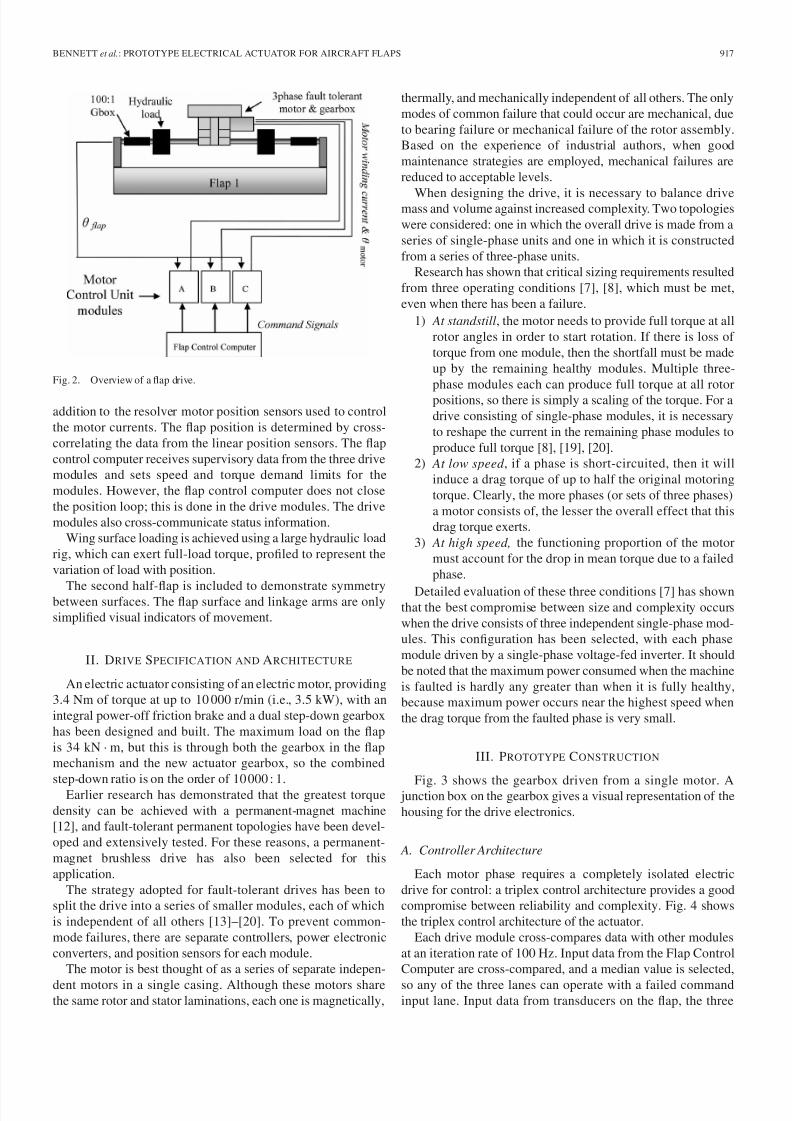
hard mechanical coupling to each end.Photographs of the demonstrator rig are shown in Fig. 1, and
the overall demonstrator rig is diagrammatically illustrated in
Fig. 2. The rig comprises one full flap section and one half-
flap section. Each flap is driven by a modular fault-tolerant
drive, with overall system control undertaken by a flap control
computer. A full description of the overall control and mon-
itoring system is beyond the scope of this paper, but a brief
description of the overall scheme will help to set the context
for the description of the actuator. The flap control computer
sets a flap position command, which is fed to three separate
drive modules (A, B, and C in Fig. 2). Each drive module has
a conventional position control using nested position, speed,
and torque loops. The angle of the flap is measured usingmultiple linear position sensors, which are separate from and in
7/28/2019 05438783
http://slidepdf.com/reader/full/05438783 3/7
BENNETT et al.: PROTOTYPE ELECTRICAL ACTUATOR FOR AIRCRAFT FLAPS 917
Fig. 2. Overview of a flap drive.
addition to the resolver motor position sensors used to control
the motor currents. The flap position is determined by cross-
correlating the data from the linear position sensors. The flap
control computer receives supervisory data from the three drive
modules and sets speed and torque demand limits for the
modules. However, the flap control computer does not close
the position loop; this is done in the drive modules. The drive
modules also cross-communicate status information.
Wing surface loading is achieved using a large hydraulic load
rig, which can exert full-load torque, profiled to represent the
variation of load with position.
The second half-flap is included to demonstrate symmetrybetween surfaces. The flap surface and linkage arms are only
simplified visual indicators of movement.
II. DRIVE SPECIFICATION AND ARCHITECTURE
An electric actuator consisting of an electric motor, providing
3.4 Nm of torque at up to 10 000 r/min (i.e., 3.5 kW), with an
integral power-off friction brake and a dual step-down gearbox
has been designed and built. The maximum load on the flap
is 34 kN · m, but this is through both the gearbox in the flap
mechanism and the new actuator gearbox, so the combined
step-down ratio is on the order of 10 000 : 1.Earlier research has demonstrated that the greatest torque
density can be achieved with a permanent-magnet machine
[12], and fault-tolerant permanent topologies have been devel-
oped and extensively tested. For these reasons, a permanent-
magnet brushless drive has also been selected for this
application.
The strategy adopted for fault-tolerant drives has been to
split the drive into a series of smaller modules, each of which
is independent of all others [13]–[20]. To prevent common-
mode failures, there are separate controllers, power electronic
converters, and position sensors for each module.
The motor is best thought of as a series of separate indepen-
dent motors in a single casing. Although these motors sharethe same rotor and stator laminations, each one is magnetically,
thermally, and mechanically independent of all others. The only
modes of common failure that could occur are mechanical, due
to bearing failure or mechanical failure of the rotor assembly.
Based on the experience of industrial authors, when good
maintenance strategies are employed, mechanical failures are
reduced to acceptable levels.
When designing the drive, it is necessary to balance drivemass and volume against increased complexity. Two topologies
were considered: one in which the overall drive is made from a
series of single-phase units and one in which it is constructed
from a series of three-phase units.
Research has shown that critical sizing requirements resulted
from three operating conditions [7], [8], which must be met,
even when there has been a failure.
1) At standstill, the motor needs to provide full torque at all
rotor angles in order to start rotation. If there is loss of
torque from one module, then the shortfall must be made
up by the remaining healthy modules. Multiple three-
phase modules each can produce full torque at all rotor
positions, so there is simply a scaling of the torque. For a
drive consisting of single-phase modules, it is necessary
to reshape the current in the remaining phase modules to
produce full torque [8], [19], [20].
2) At low speed , if a phase is short-circuited, then it will
induce a drag torque of up to half the original motoring
torque. Clearly, the more phases (or sets of three phases)
a motor consists of, the lesser the overall effect that this
drag torque exerts.
3) At high speed, the functioning proportion of the motor
must account for the drop in mean torque due to a failed
phase.
Detailed evaluation of these three conditions [7] has shownthat the best compromise between size and complexity occurs
when the drive consists of three independent single-phase mod-
ules. This configuration has been selected, with each phase
module driven by a single-phase voltage-fed inverter. It should
be noted that the maximum power consumed when the machine
is faulted is hardly any greater than when it is fully healthy,
because maximum power occurs near the highest speed when
the drag torque from the faulted phase is very small.
III. PROTOTYPE CONSTRUCTION
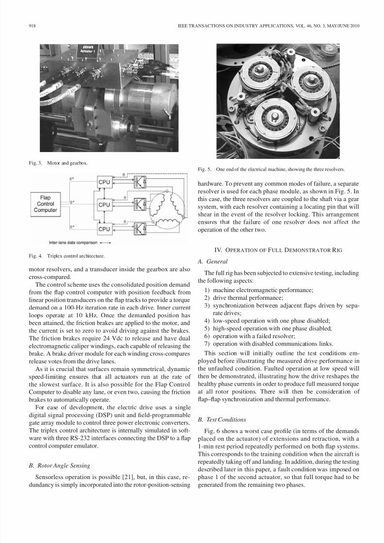
Fig. 3 shows the gearbox driven from a single motor. A junction box on the gearbox gives a visual representation of the
housing for the drive electronics.
A. Controller Architecture
Each motor phase requires a completely isolated electric
drive for control: a triplex control architecture provides a good
compromise between reliability and complexity. Fig. 4 shows
the triplex control architecture of the actuator.
Each drive module cross-compares data with other modules
at an iteration rate of 100 Hz. Input data from the Flap Control
Computer are cross-compared, and a median value is selected,
so any of the three lanes can operate with a failed commandinput lane. Input data from transducers on the flap, the three
7/28/2019 05438783
http://slidepdf.com/reader/full/05438783 4/7
918 IEEE TRANSACTIONS ON INDUSTRY APPLICATIONS, VOL. 46, NO. 3, MAY/JUNE 2010
Fig. 3. Motor and gearbox.
Fig. 4. Triplex control architecture.
motor resolvers, and a transducer inside the gearbox are also
cross-compared.
The control scheme uses the consolidated position demandfrom the flap control computer with position feedback from
linear position transducers on the flap tracks to provide a torque
demand on a 100-Hz iteration rate in each drive. Inner current
loops operate at 10 kHz. Once the demanded position has
been attained, the friction brakes are applied to the motor, and
the current is set to zero to avoid driving against the brakes.
The friction brakes require 24 Vdc to release and have dual
electromagnetic caliper windings, each capable of releasing the
brake. A brake driver module for each winding cross-compares
release votes from the drive lanes.
As it is crucial that surfaces remain symmetrical, dynamic
speed-limiting ensures that all actuators run at the rate of
the slowest surface. It is also possible for the Flap Control
Computer to disable any lane, or even two, causing the friction
brakes to automatically operate.
For ease of development, the electric drive uses a single
digital signal processing (DSP) unit and field-programmable
gate array module to control three power electronic converters.
The triplex control architecture is internally simulated in soft-
ware with three RS-232 interfaces connecting the DSP to a flap
control computer emulator.
B. Rotor Angle Sensing
Sensorless operation is possible [21], but, in this case, re-dundancy is simply incorporated into the rotor-position-sensing
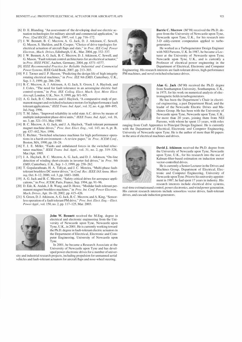
Fig. 5. One end of the electrical machine, showing the three resolvers.
hardware. To prevent any common modes of failure, a separate
resolver is used for each phase module, as shown in Fig. 5. Inthis case, the three resolvers are coupled to the shaft via a gear
system, with each resolver containing a locating pin that will
shear in the event of the resolver locking. This arrangement
ensures that the failure of one resolver does not affect the
operation of the other two.
IV. OPERATION OF FUL L DEMONSTRATOR RIG
A. General
The full rig has been subjected to extensive testing, including
the following aspects:
1) machine electromagnetic performance;
2) drive thermal performance;
3) synchronization between adjacent flaps driven by sepa-
rate drives;
4) low-speed operation with one phase disabled;
5) high-speed operation with one phase disabled;
6) operation with a failed resolver;
7) operation with disabled communications links.
This section will initially outline the test conditions em-
ployed before illustrating the measured drive performance in
the unfaulted condition. Faulted operation at low speed will
then be demonstrated, illustrating how the drive reshapes the
healthy phase currents in order to produce full measured torque
at all rotor positions. There will then be consideration of
flap–flap synchronization and thermal performance.
B. Test Conditions
Fig. 6 shows a worst case profile (in terms of the demands
placed on the actuator) of extensions and retraction, with a
1-min rest period repeatedly performed on both flap systems.
This corresponds to the training condition when the aircraft is
repeatedly taking off and landing. In addition, during the testing
described later in this paper, a fault condition was imposed on
phase 1 of the second actuator, so that full torque had to begenerated from the remaining two phases.

7/28/2019 05438783
http://slidepdf.com/reader/full/05438783 5/7
BENNETT et al.: PROTOTYPE ELECTRICAL ACTUATOR FOR AIRCRAFT FLAPS 919
Fig. 6. Load profile for worst case continuous testing.
Fig. 7. Motor torque and flap arm angles under worst case load profile +sporadic spoiler extensions.
Fig. 7 shows the motor torque requirement of a single flap
when the worst load profile condition is applied over one
extension. The basic pattern of torque comes from the aero-
dynamic load and the mechanics of the actuation mechanism.
It reaches a maximum partway through the extension. The loadtorque shown in Fig. 7 has also had, superimposed on it, seven
short periods, where the torque is increased by a factor of 3.5
to represent the extra aerodynamic loads created by spoiler
extensions (such as might happen during a landing, with the
spoilers being repeatedly deployed to slow the aircraft down as
the flaps are being extended).
C. Low-Speed Operation Unfaulted
Fig. 8 shows the measured three-phase current waveforms in
a single actuator as it starts up, producing rated torque. This
requires peak instantaneous phase currents of approximately
20 A. The actuator is initially held in position by the electric
brake, and the motor must be powered before the brake is
released to prevent runaway. Consequently, for the first 12 ms of
the test, the actuator is stationary, and initial dc currents occur.
Once running, the phase currents are essentially sinusoidal.
D. Low-Speed Operation Faulted
Fig. 9 shows the measured operation of the drive when a
phase is shut down midoperation, simulating a single-phase
fault. For this particular test case, the drive is running at
3000 r/min. The remaining healthy phases must compensate for
the faulted phase, so that the mean output torque of the driveis unaltered when operating at high speed. At low speed, the
Fig. 8. Startup currents after brake is released.
Fig. 9. Measured motor phase currents and sum output torque after phaseshutdown. The top line is the sum torque.
requirements are more stringent; the inertia of the drive may not
be enough to carry through any torque dips, and consequently,the drive must continue to produce rated torque at all rotor
positions.
The drive controller operates as described here.
1) A fault is detected, and its cause is identified by the
controller. The fault can be in the machine, the power
electronics, or the controller. Cross-comparison between
phase controllers plays a strong role in this process.
2) Once the fault is identified, actions are taken in the
hardware to limit the fault current to within rated values,
thereby preventing overheating and fault propagation. For
the example shown in Fig. 9, an open-circuit failure is
imposed, so the currents in the faulted phase are zero,giving a relatively benign condition.
3) For most fault conditions, there is no longer full control
of the current in the faulted phase. The controller then
monitors the faulted phase current and hence deduces
its instantaneous torque contribution in real time. This is
subtracted from the drive torque demand to produce an
instantaneous torque requirement for the remaining two
healthy phases.
4) The torque requirement for the two healthy phases is
apportioned between each phase according to its instanta-
neous torque constant. Real-time instantaneous per-phase
currents are then deduced using the torque constants.
This method can be shown to give the minimum rmsdrive phase current and, hence, minimum winding loss

7/28/2019 05438783
http://slidepdf.com/reader/full/05438783 6/7
920 IEEE TRANSACTIONS ON INDUSTRY APPLICATIONS, VOL. 46, NO. 3, MAY/JUNE 2010
Fig. 10. Synchronization of two flaps during extension.
[7]. Unless further modifications are made, it does not,
however, minimize the peak phase currents.
5) The waveforms in Fig. 9 show the process in action
in the drive. At a time of 0.02 s, one phase has an
open-circuit fault and can no longer contribute to torque.
The current waveforms of the remaining two phases are
boosted in certain parts of their cycle to produce a rather
unusual wave shape. Note that the periods of peak current
coincide with the times when the faulted phase would
make a major contribution to torque, and so, the healthy
currents have to be boosted by almost a factor of two. The
shaft torque for this test has been measured with a high-
bandwidth torque transducer and is also shown in Fig. 9.
The shaft torque remains unaltered by the occurrence of
the fault.
E. Flap Synchronization
Fig. 10 shows the measured positions of two adjacent flaps
during flap extensions on the test rig. There is a requirement for
the two flaps to be closely synchronized at all times, and so, the
drives for each flap must precisely be coordinated during their
movement. The torque demand upon each flap varies according
to its position on the wing, and this is also included in the
model, so the two flaps have differing loads.
To give a worst case condition, a fault has been imposed
on one phase of flap 2’s actuator. Fig. 10 shows the degree
to which the two flaps remain synchronized. Remembering the
specification that was for +/−0.25% of full-scale deflection
when retracted (i.e., close to +/−0.25◦ in this case, as full
scale is 112◦) and +/−0.5% at other positions, it can be seen
that, at certain angles, the error in the demonstrator is many
times the allowable limit. More than half of the error is actually
due to backlash in the demonstrator output gearbox; with an
operational output gearbox, the actuator will already meet the
specification. Of the rest of the error, some is due to imperfect
tuning, and the most of the rest relates to the accuracy of the
position feedback. It will be possible to get synchronization
accuracy well within the tolerance.
F. Thermal Performance
Fig. 11 shows the temperature measured at the center of awinding (which is the location of the hot spot in the machine)
Fig. 11. Thermal performance of two actuators (higher trace running faulted).
of two actuators driving adjacent flaps with the load profile of
Fig. 7 continuously applied. The lower curve is with no faults,
whereas the upper curve is running on two phases. The lower
actuator is switched off after 1800 s to demonstrate cooling
behavior. Fitting exponentials to the measured faulted curve
reveals a maximum steady-state temperature of 91 ◦C against an
ambient of 30 ◦C, i.e., a rise of 61 ◦C. Taking a maximum am-
bient of 70 ◦C would give a maximum temperature of 131 ◦C,
which is well within the limits for the winding of about 160 ◦C.
V. CONCLUSION
A full-scale demonstrator of a distributed electrical aircraft
flap system has been built and tested. The system contains two
fault-tolerant electric drives and associated gearboxes driving
against loads typical of a flap system, produced using hydraulicloads to meet safety requirements.
The system is able to meet its specification, including syn-
chronization between adjacent flaps and operation in the event
of a machine or controller failure. Results have demonstrated
operation with a single-phase open-circuit failure. The system
detects the failure and modifies the remaining healthy phases
in order to continue to produce smooth torque at all rotor
positions. It is shown that the shaft torque remains essentially
unchanged by the fault.
ACKNOWLEDGMENT
The authors would like to thank Comar Engineering Ltd. for
the design and construction of the load rig.
REFERENCES
[1] D. T. Glass-Hooper, “The electric control of large aeroplanes,” Flight ,p. 1118, Dec. 21, 1916.
[2] J. Rea, “Boeing 777 high lift control system,” IEEE Aerosp. Electron.
Syst. Mag., vol. 8, no. 8, pp. 15–21, Aug. 1991.[3] S. C. Jensen, G. D. Jenny, and D. Dawson, “Flight test experience with
an electromechanical actuator on the F-18 systems research aircraft,” inProc. 19th DASC , Oct. 2000, vol. 1, pp. 2E3/1–2E3/10.
[4] K. C. Thompson, K. Eitenmiller, and C. L. Hunter, “Demonstrationof electric actuator technology for military transport aircraft,” in Proc.
NAECON , May 1983, p. 87.[5] K. C. Thompson and R. E. Alden, “Lockheed-Georgia and electric pri-mary flight control systems,” in Proc. NAECON , May 1985, p. 588.
7/28/2019 05438783
http://slidepdf.com/reader/full/05438783 7/7
BENNETT et al.: PROTOTYPE ELECTRICAL ACTUATOR FOR AIRCRAFT FLAPS 921
[6] D. E. Blanding, “An assessment of the developing dual use electric ac-tuation technologies for military aircraft and commercial application,” inProc. 32nd IECEC , Jul./Aug. 1997, vol. 1, pp. 716–172.
[7] J. W. Bennett, B. C. Mecrow, A. G. Jack, D. J. Atkinson, C. Sewell,G. Mason, S. Sheldon, and B. Cooper, “Choice of drive topologies forelectrical actuation of aircraft flaps and slats,” in Proc. IEE Conf. Power
Electron., Mach. Drives, Edinburgh, U.K., Mar. 2004, pp. 332–337.[8] J. W. Bennett, A. G. Jack, B. C. Mecrow, D. J. Atkinson, C. Sewell, and
G. Mason, “Fault tolerant control architectures for an electrical actuator,”in Proc. IEEE PESC , Aachen, Germany, 2004, pp. 4371–4377.[9] IEEE Recommended Practice for Reliable Industrial and Commercial
Power Systems, IEEE Gold Book, 2007, pp. 213–303.[10] P. J. Tavner and J. P. Hasson, “Predicting the design life of high integrity
rotating electrical machines,” in Proc. IEE 9th EMD, Canterbury, U.K.,Sep. 1–3, 1999, pp. 286–290.
[11] B. C. Mecrow, A. J. Atkinson, A. G. Jack, S. Green, J. A. Haylock, andJ. Coles, “The need for fault tolerance in an aeroengine electric fuelcontrol system,” in Proc. IEE Colloq. Elect. Mach. Syst. More Elect.
Aircraft , London, U.K., Nov. 9, 1999, pp. 9/1–9/5.[12] A. G. Jack, B. C. Mecrow, and J. Haylock, “A comparative study of per-
manent magnet and switched reluctance motors for highperformance faulttolerant applications,” IEEE Trans. Ind. Appl., vol. 32, no. 4, pp. 889–895,Jul./Aug. 1996.
[13] T. M. Jahns, “Improved reliability in solid state A.C. drives by means of multiple independent phase-drive units,” IEEE Trans. Ind. Appl., vol. 16,
no. 3, pp. 321–331, May 1980.[14] B. C. Mecrow, A. G. Jack, and J. A. Haylock, “Fault tolerant permanent
magnet machine drives,” Proc. Inst. Elect. Eng., vol. 143, no. 6, pt. B,pp. 437–442, Nov. 1996.
[15] E. Richter, “Switched reluctance machines for high performance opera-tions in a harsh environment—A review paper,” in Proc. ICEM Conf.,Boston, MA, 1990, pp. 18–24.
[16] T. J. E. Miller, “Faults and unbalanced forces in the switched reluc-tance machine,” IEEE Trans. Ind. Appl., vol. 31, no. 2, pp. 319–328,Mar./Apr. 1995.
[17] J. A. Haylock, B. C. Mecrow, A. G. Jack, and D. J. Atkinson, “On-linedetection of winding short-circuits in inverter fed drives,” in Proc. 9th
EMD, Canterbury, U.K., Sep. 1–3, 1999, pp. 258–262.[18] T. Gopalarathnam, H. A. Toliyat, and J. C. Moreira, “Multi-phase fault-
tolerant brushless DC motor drives,” in Conf. Rec. IEEE IAS Annu. Meet-
ing, Oct. 8–12, 2000, vol. 3, pp. 1683–1688.
[19] A. G. Jack and B. C. Mecrow, “Safety critical drives for aerospace appli-cations,” in Proc. ICEM , Paris, France, Sep. 1994, pp. 91–96.[20] D. Ede, K. Atalah, J. B. Wang, and D. Howe, “Modular fault-tolerant per-
manent magnet brushless machines,” in Proc. Int. Conf. Power Electron.,
Mach. Drives, Apr. 16–18, 2002, pp. 415–426.[21] S. Green, D. J. Atkinson, A. G. Jack, B. C. Mecrow, and A. King, “Sensor-
less operation of a fault tolerant PM drive,” Proc. Inst. Elect. Eng.—Elect.
Power Appl., vol. 150, no. 2, pp. 117–125, Mar. 2003.
John W. Bennett received the M.Eng. degree inelectrical and electronic engineering from the Uni-versity of Newcastle upon Tyne, Newcastle uponTyne, U.K., in 2001. He is currently working towardthe Ph.D. degree in fault-tolerant electric actuators inthe Department of Electrical, Electronic and Com-puter Engineering, University of Newcastle uponTyne.
In 2001, he became a Research Associate at theUniversity of Newcastle upon Tyne and has devel-oped power electronic drives for a number of univer-
sity and industrial research projects, including propulsion for unmanned aerialvehicles and fault-tolerant actuators for aircraft flaps and nose-wheel steering.
Barrie C. Mecrow (M’98) received the Ph.D. de-gree from the University of Newcastle upon Tyne,Newcastle upon Tyne, U.K., for his research into3-D eddy-current computation applied to turbo-generators.
He worked as a Turbogenerator Design Engineerwith NEI Parsons, U.K. In 1987, he became a Lec-turer at the University of Newcastle upon Tyne,
Newcastle upon Tyne, U.K., and is currently aProfessor of electrical power engineering in theDepartment of Electrical, Electronic and Computer
Engineering. His research interests are fault-tolerant drives, high-performancePM machines, and novel switched reluctance drives.
Alan G. Jack (M’00) received the Ph.D. degreefrom Southampton University, Southampton, U.K.,in 1975, for his work on numerical analysis of elec-tromagnetic fields in turbogenerators.
He has been the Department’s Chair in electri-cal engineering, a past Department Head, and theleader of the Newcastle Electric Drives and Ma-chines Group. He has been with the University of Newcastle upon Tyne, Newcastle upon Tyne, U.K.,for more than 20 years, joining them from NEIParsons, with whom he spent 13 years, with roles
ranging from Craft Apprentice to Principal Design Engineer. He is currentlywith the Department of Electrical, Electronic and Computer Engineering,University of Newcastle upon Tyne. He is the author of more than 80 papersin the area of electrical machines and drives.
David J. Atkinson received the Ph.D. degree fromthe University of Newcastle upon Tyne, Newcastleupon Tyne, U.K., for his research into the use of Kalman-filter-based estimation on induction motorvector-controlled drives.
He is currently a Senior Lecturer in the Drives andMachines Group, Department of Electrical, Elec-tronic and Computer Engineering, University of Newcastle upon Tyne. Prior to his university appoint-
ment in 1987, he had spent 17 years in industry. Hisresearch interests include electrical drive systems,
real-time estimationand control, power electronics, and wind power generation.His current research interests include sensorless vector drives, fault-tolerantdrives, and cascade induction generators.