05 nozzle design.pptx
TRANSCRIPT

AERO0033-1, Aerothermodynamics of High Speed Flows, Lecture 5
Lecture 5:Nozzle designG. Dimitriadis
Aerothermodynamics of High Speed Flows
1
AERO0033-1, Aerothermodynamics of High Speed Flows, Lecture 5
Introduction• Before talking about nozzle design we need
to address a very important issue:– Shock reflection
• We have already stated that shocks can exist in nozzles. As nozzles are closed spaces, the shocks will extend to the walls.
• What happens when a shock reaches a wall?• The same question applies to expansion
waves.2

AERO0033-1, Aerothermodynamics of High Speed Flows, Lecture 5
Shock reflection• Consider an oblique shock with angle b1
reaching a wall.• The flow boundary condition is
impermeability: flow cannot cross the wall.
3
b1 FM1
M2
M3
q
b2
-qShock wave 1
Shock wave 2
AERO0033-1, Aerothermodynamics of High Speed Flows, Lecture 5
Discussion• The flow is deflected by an angle q behind
the shock wave.• If the shock wave disappears at the wall, the
flow will cross the solid boundary.• Therefore the shock cannot disappear, it
must be reflected.• The reflected shock must deflect the flow by
an angle -q so that the flow remains parallel to the wall.
• Note that M2<M1. Therefore, the reflected shock is weaker than the original.
4
AERO0033-1, Aerothermodynamics of High Speed Flows, Lecture 5
Example• The Mach number upstream of the oblique
shock is M1=2.8 and the angle b1 is 35o.• Calculate the angle of the reflected shock
wave to the wall F.• Also calculate the Mach number behind
the reflected shock M3.
5

AERO0033-1, Aerothermodynamics of High Speed Flows, Lecture 5
Solution• From the oblique shock tables, for M1=2.8, b1=35o:
– The flow deflection angle is q=16o.– The Mach number behind the shock is M2=2.06.
• The reflected shock must deflect the flow by q=16o
and the upstream Mach number is 2.06.• From the oblique shock tables:
– The sock angle is b2=45.56o.– The downstream Mach number is M3=1.45.– The angle F is F=b2-q=29.56o.
• Note that the original shock wave’s angle to the wall was 35o while that of the reflected wave is lower at 29.56o.
• Shock waves are not deflected at the same angle!
6

AERO0033-1, Aerothermodynamics of High Speed Flows, Lecture 5
Counter-example• The original shock wave has an angle b1=42o.
The upstream Mach number is still M1=2.8.• The deflection angle is q=22o. The
downstream Mach number is M2=1.75.• The reflected Mach number must deflect the
flow by q=22o.• There is no such shock wave for a Mach
number of 1.75. The maximum deflection angle is 18.09o.
• What happens now?
7

AERO0033-1, Aerothermodynamics of High Speed Flows, Lecture 5
Mach reflection• The oblique shock cannot reach the wall!• A normal shock forms at the wall propagating
downwards and curving to merge with the oblique shock.
• At the intersection a third curved reflected shock is formed.
8
q
Shock wave 1M1
M2
Normal shock
Curved reflected shock

AERO0033-1, Aerothermodynamics of High Speed Flows, Lecture 5
Left and right running• In the previous examples, the initial shock is left-
running:– An observer standing on the wave and looking
downstream sees the wave running off toward the left.• The reflected shock is right-running:
– An observer standing on the wave and looking downstream sees the wave running off toward the right.
9
Left-running wave Right-running wave

AERO0033-1, Aerothermodynamics of High Speed Flows, Lecture 5
Shock intersection• Consider the intersection between a left-
running and a right-running wave:
10
q2
q3
1
2
3 5
4
q5
q4
B
A
C
D
E
F
The two shocks meet at point 2. There they are refracted into two new waves with different angles.
The line CF is a slip line: Flow cannot cross it. In other words, flow in regions 4 and 5 must be parallel.
AERO0033-1, Aerothermodynamics of High Speed Flows, Lecture 5
Discussion• The flow must be parallel in regions 4 and 5
because:– If the two flow directions converge, they will cross the
slip line. Impossible– If the the two flow directions diverge, they will leave a
vacuum behind them. Impossible.• In other words, q3-q5=q2-q4.• Furthermore, the pressure in regions 4 and 5 must
be equal.– If it was not, the slip line would move until the two
pressures became equal.• In other words, p4=p5.
11

AERO0033-1, Aerothermodynamics of High Speed Flows, Lecture 5
Example• Consider the diffuser of a supersonic wind
tunnel running at M=3.• The diffuser is straight and symmetric with
an angle q=14o.• How many reflections can there be?• What will be the Mach number at the end
of the reflections?• What is the drop in total pressure?
12

AERO0033-1, Aerothermodynamics of High Speed Flows, Lecture 5
Solution• Due to symmetry, the slip line CF must be horizontal.• It follows that q2=q3=q4=q5=q.
13
q3
1
2
3
5
4
q5
q4
B
A
C
D
F
q2E
For calculating the static pressure drop across the oblique shocks, recall that upstream of an oblique shock: Mn1 =M1 sinβ
AERO0033-1, Aerothermodynamics of High Speed Flows, Lecture 5
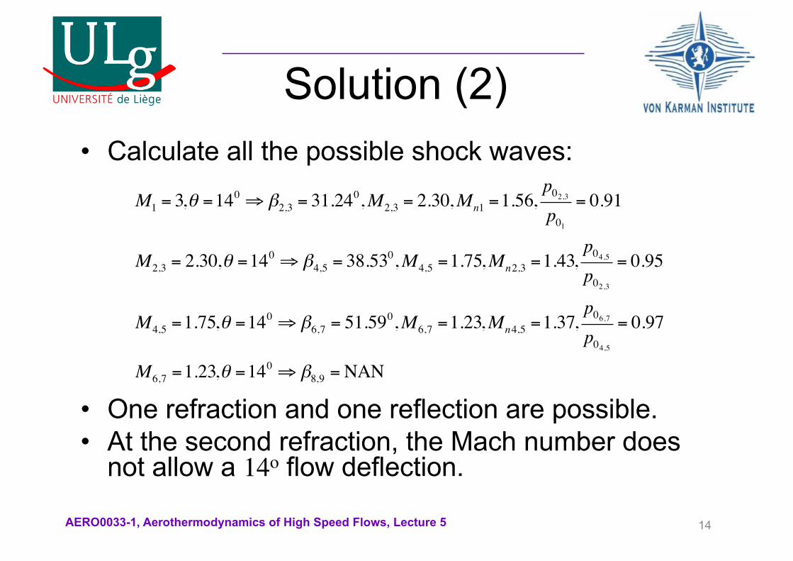
Solution (2)• Calculate all the possible shock waves:
• One refraction and one reflection are possible. • At the second refraction, the Mach number does
not allow a 14o flow deflection.
14
M1 = 3,θ =140 ⇒ β2,3 = 31.24
0,M2,3 = 2.30,Mn1 =1.56,p02,3p01
= 0.91
M2,3 = 2.30,θ =140 ⇒ β4,5 = 38.53
0,M4,5 =1.75,Mn2,3 =1.43,p04,5p02,3
= 0.95
M4,5 =1.75,θ =140 ⇒ β6,7 = 51.59
0,M6,7 =1.23,Mn4,5 =1.37,p06,7p04,5
= 0.97
M6,7 =1.23,θ =140 ⇒ β8,9 =NAN
AERO0033-1, Aerothermodynamics of High Speed Flows, Lecture 5
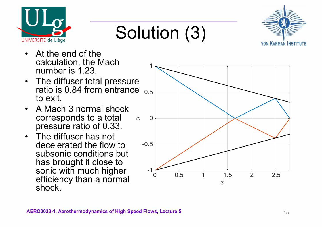
Solution (3)• At the end of the
calculation, the Mach number is 1.23.
• The diffuser total pressure ratio is 0.84 from entrance to exit.
• A Mach 3 normal shock corresponds to a total pressure ratio of 0.33.
• The diffuser has not decelerated the flow to subsonic conditions but has brought it close to sonic with much higher efficiency than a normal shock.
15
x0 0.5 1 1.5 2 2.5
y
-1
-0.5
0
0.5
1

AERO0033-1, Aerothermodynamics of High Speed Flows, Lecture 5
Practical diffusers• In practical diffusers the last shock is a very weak Mach reflection.• The normal shock associated with the Mach reflection leads to
subsonic flow.• The diffuser has two section:
– One highly inclined section where the necessary flow deflections are high.
– One flatter section where the flow deflections are much lower.• The sonic throat lies at the end of the flat section.
16From J. D. Anderson, Modern Compressible Flow
AERO0033-1, Aerothermodynamics of High Speed Flows, Lecture 5
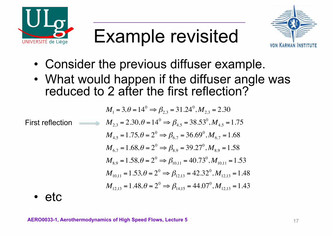
Example revisited• Consider the previous diffuser example.• What would happen if the diffuser angle was
reduced to 2 after the first reflection?
• etc
17
M1 = 3,θ =140 ⇒ β2,3 = 31.24
0,M2,3 = 2.30
M2,3 = 2.30,θ =140 ⇒ β4,5 = 38.53
0,M4,5 =1.75
M4,5 =1.75,θ = 20 ⇒ β6,7 = 36.69
0,M6,7 =1.68
M6,7 =1.68,θ = 20 ⇒ β8,9 = 39.27
0,M8,9 =1.58
M8,9 =1.58,θ = 20 ⇒ β10,11 = 40.73
0,M10,11 =1.53
M10,11 =1.53,θ = 20 ⇒ β12,13 = 42.32
0,M12,13 =1.48
M12,13 =1.48,θ = 20 ⇒ β14,15 = 44.07
0,M12,13 =1.43
First reflection

AERO0033-1, Aerothermodynamics of High Speed Flows, Lecture 5
Expansion wave reflection
• Expansion waves are also reflected:
• They are curved in the region where the incident and reflected waves intersect:– Non-simple region.
18
Incident wave Reflected wave

AERO0033-1, Aerothermodynamics of High Speed Flows, Lecture 5
Characteristic lines• Two characteristic lines pass from every point
in a supersonic flow, a left running (S+) and a right running (S-) characteristic.
• Characteristic lines are Mach lines:– The S+ characteristic has an angle q+µ, where
µ is the local Mach angle.– The S- characteristic has an angle q-µ.
• Characteristics are normally curved. The slope of the characteristic is known at a point where all the flow parameters are known.
• All points on a characteristic line have the same value of s+,-.
– The quantity s-=q+n(M) is constant on a left running characteristic.
– The quantity s+=q-n(M) is constant on a right running characteristic.
– n(M) is the Prandtl-Meyer function and q is the local flow angle.
• In the diagram on the right, points 1 and 2 lie on the same S+ and points 2 and 3 lie on the same S- characteristic:– q1-n(M1)=q2-n(M2)– q2+n(M2)=q3+n(M3)
19
1
2
3
AERO0033-1, Aerothermodynamics of High Speed Flows, Lecture 5
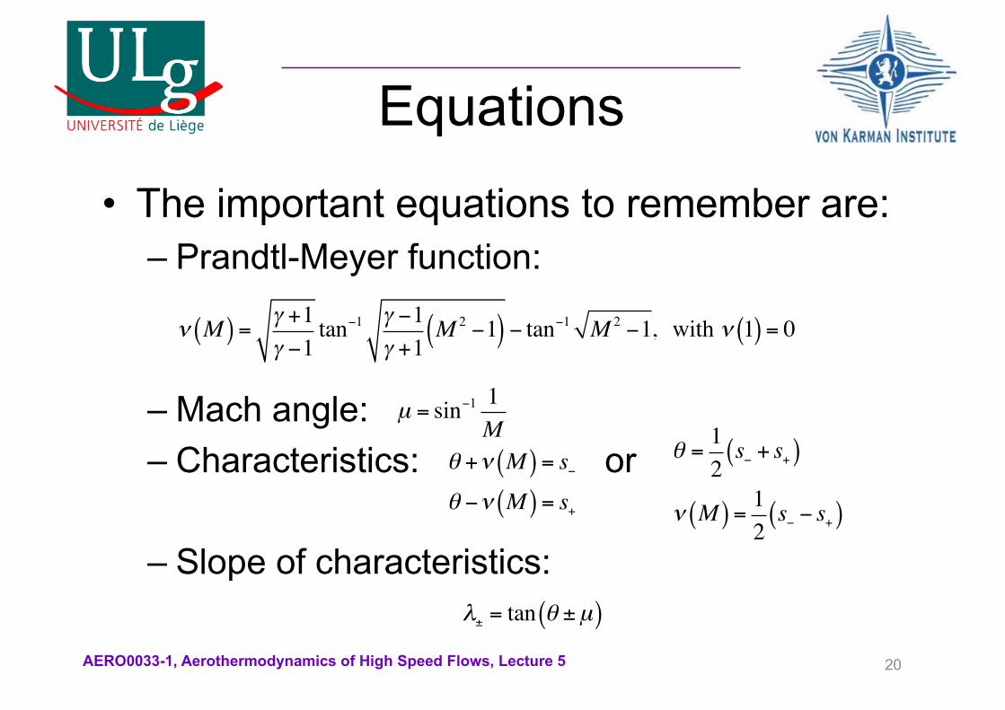
Equations• The important equations to remember are:
– Prandtl-Meyer function:
– Mach angle:– Characteristics: or
– Slope of characteristics:
20
ν M( ) = γ +1γ −1
tan−1 γ −1γ +1
M 2 −1( ) − tan−1 M 2 −1, with ν 1( ) = 0
µ = sin−1 1M
θ +ν M( ) = s−θ −ν M( ) = s+
λ± = tan θ ±µ( )
θ =12s− + s+( )
ν M( ) = 12s− − s+( )
AERO0033-1, Aerothermodynamics of High Speed Flows, Lecture 5
Linearized characteristics
• Curved characteristics cannot be easily handled.– We don’t know the shape of the curve unless we solve numerical
the flow equation.• It is possible to simplify the analysis by assuming that
characteristic lines are straight line segments.• This is a very powerful procedure:
– If we know the flow parameters at two points in the flow, we can calculate the equations of the characteristics that pass through them.
– We can then calculate the intersection of the S+ characteristic from the first point with the S- characteristic from the second.
– This intersection defines a third point in the flow, at which we can calculate all the flow parameters.
– We can also calculate the intersection of the S- characteristic from the first point with the S+ characteristic from the second.
– We have now calculated a fourth point in the flow.
21

AERO0033-1, Aerothermodynamics of High Speed Flows, Lecture 5
• The coordinates, flow angle and Mach number are known at points 1 and 2.
• We can calculate the equations of the characteristic lines, i.e.
• The coordinates of point 3 are the intersection of lines (S+)2and (S-)1.
• The coordinates of point 4 are the intersection of lines (S+)1and (S-)2.
22
Linearized characteristics (2)
1
2
34
(S-)1
(S-)2
(S+)1
(S+)2
x1,2, y1,2,θ1,2,M1,2
S+( )1,2: y = tan θ1,2 +µ1,2( ) x − x1,2( )+ y1,2
S−( )1,2: y = tan θ1,2 −µ1,2( ) x − x1,2( )+ y1,2

AERO0033-1, Aerothermodynamics of High Speed Flows, Lecture 5
• As an example, the coordinates of point 3 are given by:
• At point 3:
• These are two equations with two unknowns, q3and M3:
• We have now fully characterized point 3.
23
Linearized characteristics (3)
x3 =y1 − tan θ1 −µ1( ) x1 − y2 + tan θ2 +µ2( ) x2
tan θ2 +µ2( )− tan θ1 −µ1( )y3 = tan θ2 +µ2( ) x3 − x2( )+ y2θ3 +ν M3( ) = s−( )1 =θ1 +ν M1( )θ3 −ν M3( ) = s+( )2 =θ2 −ν M2( )
θ3 = s−( )1 + s+( )2ν M3( ) = s−( )1 − s+( )2

AERO0033-1, Aerothermodynamics of High Speed Flows, Lecture 5
Expansion wave reflection
• The reflection of a single expansion wave can be analyzed using the method of characteristics.
24
Incident wave
Reflected wave
Left running characteristic S+
Right running characteristic S-

AERO0033-1, Aerothermodynamics of High Speed Flows, Lecture 5
Nozzle design• Quasi-1D flow can give us a lot of information
on flow conditions inside a nozzle.• However, it cannot be used to design the
shape of the nozzle.• The flow is in reality 2D and must be treated
accordingly.• If the shape of the nozzle is not appropriate,
shocks can occur inside it.• We can use the method of characteristics to
design the shape of a nozzle.
25

AERO0033-1, Aerothermodynamics of High Speed Flows, Lecture 5
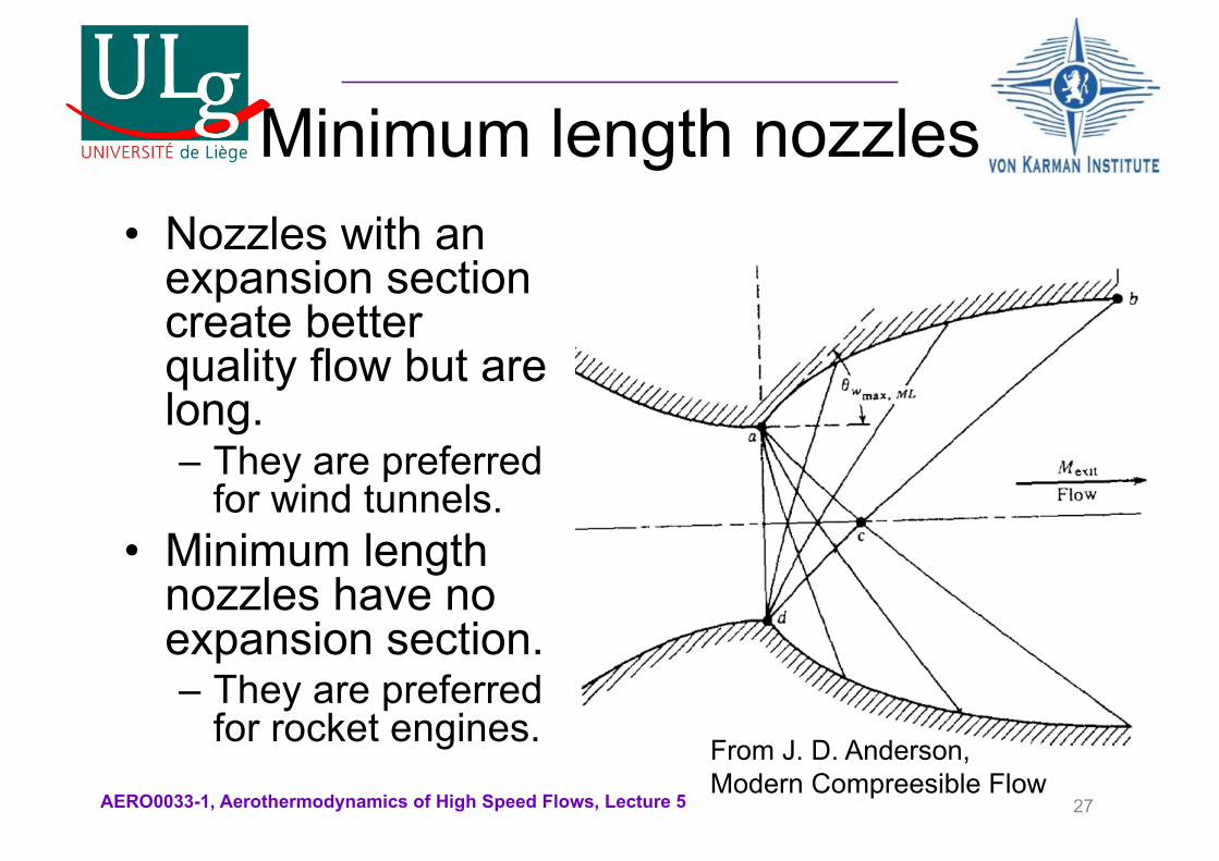
Nozzle geometry• Nozzles can contain two sections:
– An expansion section– A straightening section
26From J. D. Anderson, Modern Compreesible Flow
AERO0033-1, Aerothermodynamics of High Speed Flows, Lecture 5
Minimum length nozzles• Nozzles with an
expansion section create better quality flow but are long.– They are preferred
for wind tunnels.• Minimum length
nozzles have no expansion section.– They are preferred
for rocket engines.
27
From J. D. Anderson, Modern Compreesible Flow

AERO0033-1, Aerothermodynamics of High Speed Flows, Lecture 5
Symmetry• As with
diffusers, we can analyze only half of the nozzle if it is symmetric.
• Note that the maximum wall angle, qw,max,occursat the throat.
28
x0 1 2 3 4 5 6 7 8
y
-2
-1
0
1
2
3
4
a
b
c

AERO0033-1, Aerothermodynamics of High Speed Flows, Lecture 5
Mach number and maximum angle
• At point c the Mach number is the design Mach number, Me, and the flow direction is q=0o.
• At point b the flow direction is q=0o because the point lies on the centerline.
• Points b and c lie on the same left running characteristic, i.e.:
• Points a and b lie on the same right running characteristic, i.e:
29
θc −ν Mc( ) =θb −ν Mb( )⇒ν Mb( ) =ν Me( )
θw,max −ν Ma( ) =θb −ν Mb( )⇒θw,max −ν Ma( ) =ν Me( )

AERO0033-1, Aerothermodynamics of High Speed Flows, Lecture 5
Point a• Consider point a:
– It is a Prandtl-Meyer expansion.
– On the s+ characteristics passing through a:
– Substituting:– We can find the Mach number behind the expansion. – Note also that
30
a
qa=qw,maxMa=?
qthroat=0Mthroat=1
θthroat −ν Mthroat( ) =θa −ν Ma( )
θa =ν Ma( ) or ν Ma( ) =θw,max
s−( )a =θa +ν Ma( ) = 2θw,max, s+( )a =θa −ν Ma( ) = 0
AERO0033-1, Aerothermodynamics of High Speed Flows, Lecture 5
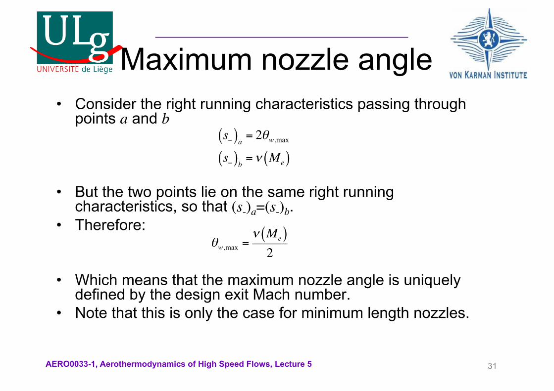
Maximum nozzle angle• Consider the right running characteristics passing through
points a and b
• But the two points lie on the same right running characteristics, so that (s-)a=(s-)b.
• Therefore:
• Which means that the maximum nozzle angle is uniquely defined by the design exit Mach number.
• Note that this is only the case for minimum length nozzles.
31
s−( )a = 2θw,maxs−( )b =ν Me( )
θw,max =ν Me( )2

AERO0033-1, Aerothermodynamics of High Speed Flows, Lecture 5
Point 1• Now consider point 1, a point on the centerline and close to the
throat.
• As the point lies on the centerline, the flow deflection must be zero.• However, we cannot start the scheme if we set the flow deflection to
zero.• Instead, we choose a small flow deflection Dq.• Then, • And, hence
32
a qw,max
qa=0Ma=1
1 q1=DqM1=?
θa −ν Ma( ) =θ1 −ν M1( ) or ν M1( ) = Δθs−( )1 =θ1 +ν M1( ) = 2Δθ, s+( )1 =θ1 −ν M1( ) = 0

AERO0033-1, Aerothermodynamics of High Speed Flows, Lecture 5
Expansion fan• Now we can draw the entire expansion fan as n lines.
• The flow deflections caused by the expansion linear are equally spaced from Dq to qw,max.
• As they are all characteristic lines passing by point a, they will be characterized by:
• As they are all right-running, the slope of each line is given by:
33
λ− j = tan θ j −µ j( ) = tan θ j − sin−1 1M j
"
#$$
%
&''
s−( ) j = 2θ j, s+( ) j =θ j −ν M j( ) = 0

AERO0033-1, Aerothermodynamics of High Speed Flows, Lecture 5
Expansion fan (2)• The current form of the
expansion fan is straight lines.
• However, we know that each characteristic line will be reflected from the centerline.
• Reflected characteristics will interact with the incident characteristics.
• This phenomenon has not been computed yet.
34
x0 0.5 1 1.5 2 2.5 3
y
-0.5
0
0.5
1
1.5
1 9 16 22 27 31 34

AERO0033-1, Aerothermodynamics of High Speed Flows, Lecture 5
Point 1 (again)• Two characteristics pass by point 1:
– The right running with slope– The left running with slope
• As point 1 lies on the centerline, the two characteristics describe fully the reflection of the expansion wave:– The right running characteristic is the incident wave– The left running characteristic is the reflected wave.
• Recall that we decided that q1=Dq. Therefore the two waves are not reflected at the same angle.
35
λ−1 = tan θ1 −µ1( )λ−1 = tan θ1 +µ1( )

AERO0033-1, Aerothermodynamics of High Speed Flows, Lecture 5
First reflection• Point 2 is the intersection of
the left running characteristic from point 1 with the right running characteristic a-9.
• Point 3 is the intersection of the left running characteristic from point 2 with the right running characteristic a-16.
• Point 4 is the intersection of the left running characteristic from point 3 with the right running characteristic a-22.
• Etc.
36
x0 0.5 1 1.5 2 2.5 3
y
-0.5
0
0.5
1
1.5
1 9 16 22 27 31 34
234567

AERO0033-1, Aerothermodynamics of High Speed Flows, Lecture 5
Intersection with the wall• The point where the
reflected characteristic reaches the wall is the intersection between the left running characteristic from point 7 and the wall.
• The wall is modeled as a straight line with slope tanqw,max.
• The wave is cancelled at the wall; it will not be reflected.
37
x0 0.5 1 1.5 2 2.5 3
y
-0.5
0
0.5
1
1.5
1 9 16 22 27 31 34
234567
8

AERO0033-1, Aerothermodynamics of High Speed Flows, Lecture 5
Point 9• Point 9 has not been properly calculated
yet.• It lies on the same right running
characteristic as point 2. Therefore (s-)9=(s-)2.
• As point 9 lies on the centerline, q=0. This means that:
• Its left running characteristic is given by
38
s−( )9 =θ9 +ν M9( )⇒ν M9( ) = s−( )2
s+( )9 =θ9 −ν M9( )⇒ s+( )9 = −ν M9( )

AERO0033-1, Aerothermodynamics of High Speed Flows, Lecture 5
Pinpointing points 9-15• Point 9 is the intersection of the right running
characteristic from point 2 and the centerline.• We can generalize by saying that any point lying on
the centerline is the intersection between the right running characteristic from the second point on the previous reflection and the centerline.
• Point 10 is the intersection between the right running characteristic from point 3 and the left running characteristic from point 9.
• And so on until we get to point 14.• Point 15 lies on the wall. All its values (Mach number,
deflection angle, characteristics etc) are equal to point 14.
39

AERO0033-1, Aerothermodynamics of High Speed Flows, Lecture 5
Two reflections• The result
after the reflections of two expansion waves is the following:
40
x0 0.5 1 1.5 2 2.5 3
y
0
0.5
1
1.5
2
1
234567
8
9
10
1112
1314
15

AERO0033-1, Aerothermodynamics of High Speed Flows, Lecture 5
Complete nozzle• After n reflections
we had the complete design.
• The Mach number at points 34 and 35 is the desired Mach number.
41
x0 1 2 3 4 5 6 7 8
y
-2
-1
0
1
2
3
4
1
234567
8
91011
121314
15
16171819
20
21
22232425
26
272829
30
3132
33
34
35

AERO0033-1, Aerothermodynamics of High Speed Flows, Lecture 5
Discussion• The method is
approximate:– Characteristic lines
are not truly straight.– They are
approximated as straight.
• Even the sonic line is curved in reality.
• Better approximations can be obtained using finite differences.
42
x0 1 2 3 4 5 6 7 8
y
-2
-1
0
1
2
3
4