05 creating models
TRANSCRIPT

Creating Models
Starting a Project
Elements and Element Attributes
Adding Elements to Your Model
Manipulating Elements
Editing Element Attributes
Using Named Views
Using Selection Sets
Using the Network Navigator
Using Prototypes
Zones
Engineering Libraries
Hyperlinks
Using Queries
User Data Extensions
Starting a Project
When you first start Bentley HAMMER V8 XM Edition, the Welcome dialog box opens.
The Welcome dialog box contains the following controls:
To Access the Welcome Dialog During Program Operation
Click the Help menu and select the Welcome Dialog command.
To Disable the Automatic Display of the Welcome Dialog Upon Startup
In the Welcome dialog, turn off the box labeled Show This Dialog at Start.
To Enable the Automatic Display of the Welcome Dialog Upon Startup
In the Welcome dialog, turn on the box labeled Show This Dialog at Start.
Bentley HAMMER V8 XM Edition Projects
All data for a model are stored in Bentley HAMMER as a project. Bentley HAMMER project files have the file name extension .wtg. You can assign a title, date, notes and other identifying information about each project using the Project Properties dialog box. You can have up to five Bentley HAMMER projects open at one time.
To Start a New Project
To start a new project, choose File > New or press <Ctrl+N>. An untitled project is opened in the drawing pane.
To Open an Existing Project
To open an existing project, choose File > Open or press <Ctrl+O>. A dialog box opens allowing you to browse for the project you want to open.
To Switch Between Multiple Projects
To switch between multiple open projects, select the appropriate tab at the top of the drawing pane. The file name of the project is displayed on the tab.
Setting Project Properties
The Project Properties dialog box allows you to enter project-specific information to help identify the project. Project properties are stored with the project.
The dialog box contains the following text fields and controls:
To set project properties
1. Choose File > Project Properties and the Project Properties dialog box opens.
2. Enter the information in the Project Properties dialog box and click OK.
Setting Options
You can change global settings for Bentley HAMMER in the Options dialog box. Choose Tools > Options. The Options dialog box contains different tabs where you can change settings.
Click one of the following links to learn more about the Options dialog box:
Options Dialog Box - Global Tab
Options Dialog Box - Project Tab
Options Dialog Box - Drawing Tab
Options Dialog Box - Units Tab
Options Dialog Box - Labeling Tab
Quick Start Lessons Opens the online help to the Quick Start Lessons Overview topic.
Create New Project Creates a new Bentley HAMMER project. When you click this button, an untitled Bentley HAMMER V8 XM Edition project is created.
Open Existing Project Opens an existing project. When you click this button, a Windows browse dialog box opens allowing you to browse to the project to be opened.
Open from ProjectWise Open an existing Bentley HAMMER project from ProjectWise. You are prompted to log into a ProjectWise datasource if you are not already logged in.
Show This Dialog at Start When selected, the Welcome dialog box opens whenever you start Bentley HAMMER V8 XM Edition. Turn off this box if you do not want the Welcome dialog box to open whenever you start Bentley HAMMER V8 XM Edition.
Title Enter a title for the project.
File Name Displays the file name for the current project. If you have not saved the project yet, the file name is listed as "Untitledx.wtg.", where x is a number between 1 and 5 chosen by the program based on the number of untitled projects that are currently open.
Engineer Enter the name of the project engineer.
Company Enter the name of your company.
Date Click this field to display a calendar, which is used to set a date for the project.
Notes Enter additional information about the project.
Página 1 de 26Creating Models
02/04/2011file://C:\Documents and Settings\PC-LIONEL\Configuración local\Temp\~hhDEAC.htm

Options Dialog Box - ProjectWise Tab
Options Dialog Box - Global Tab
The Global tab changes general program settings for the Bentley HAMMER stand-alone editor, including whether or not to display the status pane, as well as window color and layout settings.
The Global tab contains the following controls:
Stored Prompt Responses Dialog Box
This dialog allows you to change the behavior of command prompts back to their default settings. Some commands trigger a command prompt that can be suppressed by using the Do Not Prompt Again check box. You can turn the prompt back on by accessing this dialog and unchecking the box for that prompt type.
Options Dialog Box - Project Tab
This tab contains miscellaneous settings. You can set pipe length calculation, spatial reference, label display, and results file options in this tab.
The Project tab contains the following controls:
Options Dialog Box - Drawing Tab
This tab contains drawing layout and display settings. You can set the scale that you want to use as the finished drawing scale for the plan view output. Drawing scale is based upon engineering judgment and the destination sheet sizes to be used in the final presentation.
General Settings
Backup Levels Indicates the number of backup copies that are retained when a project is saved. The default value is 1.
Note: The higher this number, the more .BAK files (backup files) are created, thereby using more hard disk space on your computer.
Show Recently Used Files When selected, activates the recently opened files display at the bottom of the File menu. This check box is turned on by default.
Recent Files Maximum Indicates the maximum number of recently opened files that are displayed in the File menu. Enter a number from 1 to 15. This field is only available when the Recent Files Visible check box is turned on.
Show Status Pane When turned on, activates the Status Pane display at the bottom of the Bentley HAMMER stand-alone editor. This check box is turned on by default.
Show Welcome Page on Startup
When turned on, activates the Welcome dialog that opens when you first start Bentley HAMMER. This check box is turned on by default.
Zoom Extents On Open When turned on, a Zoom Extents is performed automatically in the drawing pane.
Compact Database Enabled
When turned on, the Bentley HAMMER database is automatically compacted when you choose File > Open. The Opens Between Compact Prompt field become available when this option is selected.
Opens Between Compact Prompt
Indicates how many times a single project can be saved before the Bentley HAMMER database is compacted. The default value is 10, which means that when the Compact Database Enabled option is selected, the database will be compacted every ten times you save a single project.
Prompts Opens the Stored Prompt Responses dialog, which allows you to change the behavior of the default prompts (messages that appear allowing you to confirm or cancel certain operations).
Window Color
Background Color Displays the color that is currently assigned to the drawing pane background. You can change the color by clicking the ellipsis (...) to open the Color dialog box.
Foreground Color Displays the color that is currently assigned to elements and labels in the drawing pane. You can change the color by clicking the ellipsis (...) to open the Color dialog box.
Read Only Background Color
Displays the color that is currently assigned to read-only data field backgrounds. You can change the color by clicking the ellipsis (...) to open the Color dialog box.
Read Only Foreground Color
Displays the color that is currently assigned to read-only data field text. You can change the color by clicking the ellipsis (...) to open the Color dialog box.
Selection Color Displays the color that is currently applied to highlighted elements in the drawing pane. You can change the color by clicking the ellipsis (...) to open the Color dialog box.
Layout
Display Inactive Topology When turned on, activates the display of inactive elements in the drawing pane in the color defined in Inactive Topology Line Color. When turned off, inactive elements will not be visible in the drawing pane. This check box is turned on by default.
Inactive Topology Line Color
Displays the color currently assigned to inactive elements. You can change the color by clicking the ellipsis (...) to open the Color dialog box.
Auto Refresh Activates Auto Refresh. When Auto Refresh is turned on, the drawing pane automatically updates whenever changes are made to the Bentley HAMMER datastore. This check box is turned off by default.
Sticky Tool Palette When turned on, activates the Sticky Tools feature. When Sticky Tools is turned on, the drawing pane cursor does not reset to the Select tool after you create a node or finish a pipe run in your model, allowing you to continue dropping new elements into the drawing without re-selecting the tool. When Sticky Tools is turned off, the drawing pane cursor resets to the Select tool after you create a node. This check box is selected by default.
Select Polygons by Edge Selects polygons in your model at their edges instead of anywhere inside the polygon. This check box is turned off by default.
Selection Handle Size In Pixels
Specifies, in pixels, the size of the handles that appear on selected elements. Enter a number from 1 to 10.
Default Drawing Style Allows you to select GIS or CAD drawing styles. Under GIS style, the size of element symbols in the drawing pane will remain the same regardless of zoom level. Under CAD style, element symbols will appear larger or smaller depending on zoom level.
Geospatial Options
Spatial Reference Used for integration with Projectwise. Can leave the field blank if there is no spatial information.
Element Identifier Options
Element Identifier Format Specifies the format in which reference fields are used. Reference fields are fields that link to another element or support object (pump definitions, patterns, controls, zones, etc.).
Result Files
Specify Custom Results File Path? When checked, allows you to edit the results file path and format by enabling the other controls in this section.
Root Path Allows you to specify the root path where results files are stored. You can type the path manually or choose the path from a Browse dialog by clicking the ellipsis (...) button.
Path Format Allows you to specify the path format. You can type the path manually and use predefined attributes from the menu accessed with the [>] button.
Path Displays a dynamically updated view of the custom result file path based on the settings in the Root Path and Path Format fields
Pipe Length
Round Pipe Length to Nearest The program will round to the nearest unit specified in this field when calculating scaled pipe length
Calculate Pipe Lengths Using Node Elevations (3D Length) When checked, includes differences in Z (elevation) between pipe ends when calculating pipe length.
Página 2 de 26Creating Models
02/04/2011file://C:\Documents and Settings\PC-LIONEL\Configuración local\Temp\~hhDEAC.htm

The Drawing tab contains the following controls:
Options Dialog Box - Units Tab
The Units tab modifies the unit settings for the current project.
The Units tab contains the following controls:
Options Dialog Box - Labeling Tab
The Element Labeling tab is used to specify the automatic numbering format of new elements as they are added to the network. You can save your settings to an .xml file for later use.
The Element Labeling tab contains the following controls:
Drawing Scale
Drawing Mode Selects either Scaled or Schematic mode for models in the drawing pane.
Horizontal Scale Factor 1 in. =:
Controls the scale of the plan view.
Annotation Multipliers
Symbol Size Mulitplier Increases or decreases the size of your symbols by the factor indicated. For example, a multiplier of 2 would result in the symbol size being doubled. The program selects a default symbol height that corresponds to 4.0 ft. (approximately 1.2 m) in actual-world units, regardless of scale.
Text Size Multiplier Increases or decreases the default size of the text associated with element labeling by the factor indicated. The program automatically selects a default text height that displays at approximately 2.5 mm (0.1 in) high at the user-defined drawing scale. A scale of 1.0 mm = 0.5 m, for example, results in a text height of approximately 1.25 m. Likewise, a 1 in. = 40 ft. scale equates to a text height of around 4.0 ft.
Text Options
Align Text with Pipes Turns text alignment on and off. When it is turned on, labels are aligned to their associated pipes. When it is turned off, labels are displayed horizontally near the center of the associated pipe.
Color Element Annotations
When this box is checked, color coding settings are applied to the element annotation.
Save As Saves the current unit settings as a separate .xml file. This file allows you to reuse your Units settings in another project. When the button is clicked, a Windows Save As dialog box opens, allowing you to enter a name and specify the directory location of the .xml file.
Load Loads a previously created Units project .xml file, thereby transferring the unit and format settings that were defined in the previous project. When the button is clicked, a Windows Load dialog box opens, allowing you to browse to the location of the desired .xml file.
Reset Defaults - SI Resets the unit and formatting settings to the original factory defaults for the System International (Metric) system.
Reset Defaults - US Resets the unit and formatting settings to the original factory defaults for the Imperial (U.S.) system.
Default Unit System for New Project
Specifies the unit system that is used globally across the project. Note that you can locally change any number of attributes to the unit system other than the ones specified here.
Units Table The units table contains the following columns:
Label—Displays the parameter measured by the unit.
Unit—Displays the type of measurement. To change the unit of an attribute type, click the choice list and click the unit you want. This option also allows you to use both U.S. customary and SI units in the same worksheet.
Display Precision—Sets the rounding of numbers and number of digits displayed after the decimal point. Enter a negative number for rounding to the nearest power of 10: (-1) rounds to 10, (-2) rounds to 100, (-3) rounds to 1000, and so on. Enter a number from 0 to 15 to indicate the number of digits after the decimal point.
Format Menu—Selects the display format used by the current field. Choices include:
Scientific—Converts the entered value to a string of the form "-d.ddd...E+ddd" or "-d.ddd...e+ddd", where each 'd' indicates a digit (0-9). The string starts with a minus sign if the number is negative.
Fixed Point—Abides by the display precision setting and automatically enters zeros after the decimal place to do so. With a display precision of 3, an entered value of 3.5 displays as 3.500.
General—Truncates any zeros after the decimal point, regardless of the display precision value. With a display precision of 3, the value that would appear as 5.200 in Fixed Point format displays as 5.2 when using General format. The number is also rounded. So, an entered value of 5.35 displays as 5.4, regardless of the display precision.
Number—Converts the entered value to a string of the form "-d,ddd,ddd.ddd...", where each 'd' indicates a digit (0-9). The string starts with a minus sign if the number is negative. Thousand separators are inserted between each group of three digits to the left of the decimal point.
Note: The conversion for pressure to ft. (or m) H20 uses the specific gravity of water at 4C (39F), or a specific gravity of 1. Hence, if the fluid being used in the simulation uses a specific gravity other than 1, the sum of the pressure in ft. (or m) H20 and the node elevation will not be exactly equal to the calculated hydraulic grade line (HGL).
Save As Saves your element labeling settings to an element label project file, which is an. xml file.
Load Opens an existing element label project file.
Reset Assigns the correct Next value for all elements based on the elements currently in the drawing and the user-defined values set in the Increment, Prefix, Digits, and Suffix fields of the Labeling table.
Labeling Table The labeling table contains the following columns:
Element—Shows the type of element to which the label applies.
On—Turns automatic element labeling on and off for the associated element type.
Next—Type the integer you want to use as the starting value for the ID number portion of the label. Bentley HAMMER V8 XM Edition generates labels beginning with this number and chooses the first available unique label.
Increment—Type the integer that is added to the ID number after each element is created to yield the number for the next element.
Prefix—Type the letters or numbers that appear in front of the ID number for the elements in your network.
Digits—Type the minimum number of digits that the ID number has. For instance, 1, 10, and 100 with a digit setting of two would be 01, 10, and 100.
Suffix—Type the letters or numbers that appear after the ID number for the elements in your network.
Preview—Displays what the label looks like based on the information you have entered in the previous fields.
Página 3 de 26Creating Models
02/04/2011file://C:\Documents and Settings\PC-LIONEL\Configuración local\Temp\~hhDEAC.htm

Options Dialog Box - ProjectWise Tab
The ProjectWise tab contains options for using Bentley HAMMER with ProjectWise.
This tab contains the following controls:
For more information about ProjectWise, see the Working with ProjectWise topic.
Working with ProjectWise
Bentley ProjectWise provides managed access to Bentley HAMMER content within a workgroup, across a distributed organization, or among collaborating professionals. When ProjectWise is integrated with Bentley HAMMER, project files can be accessed quickly, checked out for use, and checked back in directly from within Bentley HAMMER.
If ProjectWise is installed on your system, Bentley HAMMER automatically installs all the components necessary for you to use ProjectWise to store and share your Bentley HAMMER projects.
To learn more about ProjectWise, refer to the ProjectWise online help.
ProjectWise and Bentley HAMMER V8 XM Edition
Follow these guidelines when using Bentley HAMMER with ProjectWise:
Use the File > ProjectWise commands to perform ProjectWise file operations, such as Save, Open, and Change Datasource.
The first time you choose one of the File > ProjectWise menu commands in your current Bentley HAMMER session, you are prompted to log into a ProjectWise datasource. The datasource you log into remains the current datasource until you change it using the File > ProjectWise > Change Datasource command.
Use Bentley HAMMER's File > New command to create a new project. The project is not stored in ProjectWise until you select File > ProjectWise > Save As.
Use Bentley HAMMER's File > Open command to open a local copy of the current project.
Use Bentley HAMMER's File > Save command to save a copy of the current project to your local computer.
When you Close a project already stored in ProjectWise using File > Close, you are prompted to select one of the following options:
Check In—Updates the project in ProjectWise with your latest changes and unlocks the project so other ProjectWise users can edit it.
Unlock—Unlocks the project so other ProjectWise users can edit it but does not update the project in ProjectWise. Note that this will abandon any changes you have made since the last server update.
Leave Out—Leaves the project checked out so others cannot edit it and retains any changes you have made since the last server update to the files on your local computer. Select this option if you want to exit Bentley HAMMER V8 XM Edition but continue working on the project later.
In the Bentley HAMMER Options dialog box, there is a ProjectWise tab with the Update server on Save check box. This option, when turned on, can significantly affect performance, especially for large, complex projects. When this is checked, any time you save your Bentley HAMMER project locally using the File > Save menu command, the files on your ProjectWise server will also be updated and all changes to the files will immediately become visible to other ProjectWise users. This option is turned off by default.
In this release of Bentley HAMMER, calculation result files are not managed inside ProjectWise. A local copy of results is maintained on your computer, but to ensure accurate results you should recalculate projects when you first open them from ProjectWise.
Bentley HAMMER projects associated with ProjectWise appear in the Most Recently Used Files list (at the bottom of the File menu) in the following format:
pwname://PointServer:_TestDatasource/Documents/TestFolder/Test1.prj
Performing ProjectWise Operations from within Bentley HAMMER
You can quickly tell whether or not the current Bentley HAMMER project is in ProjectWise or not by looking at the title bar and the status bar of the Bentley HAMMER window. If the current project is in ProjectWise, "pwname://" will appear in front of the file name in the title bar, and a ProjectWise icon will appear on the far right side of the status bar, as shown below.
You can perform the following ProjectWise operations from within Bentley HAMMER:
To save an open Bentley HAMMER project to ProjectWise
1. In Bentley HAMMER, select File > ProjectWise > Save As.
2. If you haven't already logged into ProjectWise, you are prompted to do so. Select a ProjectWise datasource, type your ProjectWise user name and password, then click Log in.
3. In the ProjectWise Save Document dialog box, enter the following information:
a. Click Change next to the Folder field, then select a folder in the current ProjectWise datasource in which to store your project.
b. Type the name of your Bentley HAMMER project in the Name field. We recommend that you keep the ProjectWise name the same as or as close to the Bentley HAMMER project name as possible.
c. Keep the default entries for the rest of the fields in the dialog box.
d. Click OK.
To open a Bentley HAMMER project from a ProjectWise datasource
1. Select File > ProjectWise > Open.
2. If you haven't already logged into ProjectWise, you are prompted to do so. Select a ProjectWise datasource, type your ProjectWise user name and password, then click Log in.
3. In the ProjectWise Select Document dialog box, perform these steps:
a. From the Folder drop-down menu, select a folder that contains Bentley HAMMER projects.
b. In the Document list box, select a Bentley HAMMER project.
c. Keep the default entries for the rest of the fields in the dialog box.
d. Click Open.
To copy an open Bentley HAMMER project from one ProjectWise datasource to another
1. Select File > ProjectWise > Open to open a project stored in ProjectWise.
2. Select File > ProjectWise > Change Datasource.
3. In the ProjectWise Log in dialog box, select a different ProjectWise datasource, then click Log in.
4. Select File > ProjectWise > Save As.
5. In the ProjectWise Save Document dialog box, change information about the project as required, then click OK.
To make a local copy of a Bentley HAMMER project stored in a ProjectWise datasource
1. Select File > ProjectWise > Open.
2. If you haven't already logged into ProjectWise, you are prompted to do so. Select a ProjectWise datasource, type your ProjectWise user name and password, then click Log in.
3. Select File > Save As.
4. Save the Bentley HAMMER project to a folder on your local computer.
To change the default ProjectWise datasource
1. Start Bentley HAMMER.
2. Select File > ProjectWise > Change Datasource.
3. In the ProjectWise Log in dialog box, type the name of ProjectWise datasource you want to log into, then click Log in.
To use background layer files with ProjectWise
Using File > ProjectWise > Save As—If there are background files, you are prompted with two options: you can copy the background layer files to the project folder for use by the project, or you can remove the background references and manually reassign them once the project is in ProjectWise to other existing ProjectWise documents.
Using File > ProjectWise > Open—This works the same as the normal ProjectWise > Open command, except that background layer files are not locked in ProjectWise for the current user to edit. The files are intended to be shared with other users at the same time.
To add a background layer file reference to a project that exists in ProjectWise
Using File > Save As—When you use File > Save As on a project that is already in ProjectWise and there are background layer files, you are prompted with two options: you can copy all the files to the local project folder for use by the project, or you can remove the background references and manually reassign them after you have saved the project locally.
Using ProjectWise with Bentley HAMMER for AutoCAD
Bentley HAMMER for AutoCAD maintains a one to one relationship between the AutoCAD drawing (.dwg) and the Bentley HAMMER project file. When using ProjectWise with this data, we recommend that you create a Set in the ProjectWise Explorer. Included in this set should be the AutoCAD drawing (example.dwg), the Bentley HAMMER database (example.wtg.mdb), the Bentley HAMMER project file (example.wtg), and optionally for stand-alone, the stand-alone drawing setting file (example.wtg.dwh).
If you use the Set and the ProjectWise Explorer for all of your check-in / check-out procedures, you will maintain the integrity of this relationship. We recommend that you do not use the default ProjectWise integration in AutoCAD, as this will only work with the .dwg file.
About ProjectWise Geospatial
ProjectWise Geospatial gives spatial context to Municipal Products Group product projects in their original form. An interactive map-based interface allows users to navigate and retrieve content based upon location. The environment includes integrated map management, dynamic coordinate system support, and spatial indexing tools.
ProjectWise Geospatial supports the creation of named spatial reference systems (SRSs) for 2D or 3D cartesian coordinate systems, automatic transformations between SRSs, creation of Open GIS format geometries, definition of spatial locations, association of documents and folders with spatial locations, and the definition of spatial criteria for document searching.
A spatial location is the combination of a geometry for a project plus a designated SRS. It provides a universal mechanism for graphically relating ProjectWise documents and folders.
The ProjectWise administrator can assign background maps to folders, against which the contained documents or projects will be registered and displayed. For documents such as Municipal Products Group product projects, ProjectWise Geospatial can automatically retrieve the embedded spatial location. For documents that are nonspatial, the document can simply inherit the location of the folder into which it is inserted, or users can explicitly assign a location, either by typing in coordinates, or by drawing them.
Each document is indexed to a universal coordinate system or SRS, however, the originating coordinate system of each document is also preserved. This enables search of documents across the boundary of different geographic, coordinate, or engineering coordinate systems.
Custom geospatial views can be defined to display documents with symbology mapped to arbitrary document properties such as author, time, and workflow state.
For a complete description of how to work with ProjectWise Geospatial, for example how to add background maps and coordinate systems, see the ProjectWise Geospatial Explorer Guide and the ProjectWise Geospatial Administrator Guide.
Maintaining Project Geometry
A spatial location is comprised of an OpenGIS-format geometry plus a Spatial Reference System (SRS). For Municipal Products Group product projects, the product attempts to automatically calculate and maintained this geometry, as the user interacts with the model. Most transformations such as additions, moves, and deletes result in the bounding box or drawing extents being automatically updated.
Whenever the project is saved and the ProjectWise server is updated, the stored spatial location on the server, which is used for registration against any background map, will be updated also. (Note the timing of this update will be affected by the "Update Server When Saving" option on the Tools-Options-ProjectWise tab.)
Most of the time the bounding box stored in the project will be correct. However, for performance reasons, there are some rare situations where the geometry can become out of date with respect to the model. To guarantee the highest accuracy, the user can always manually update the geometry by using "Compact Database" or "Update Database Cache" as necessary, before saving to ProjectWise.
Default Datasource Displays the current ProjectWise datasource. If you have not yet logged into a datasource, this field will display <login>. To change the datasource, click the Ellipses (...) to open the Change Datasource dialog box. If you click Cancel after you have changed the default datasource, the new default datasource is retained.
Update server on Save When this is turned on, any time you save your Bentley HAMMER project locally using the File > Save menu command, the files on your ProjectWise server will also be updated and all changes to the files will immediately become visible to other ProjectWise users. This option is turned off by default.
Note: This option, when turned on, can significantly affect performance, especially for large, complex projects.
Note: These settings affect ProjectWise users only.
Note: When you remove a background layer file reference from a project that exists in ProjectWise, the reference to the file is removed but the file itself is not deleted from ProjectWise.
Página 4 de 26Creating Models
02/04/2011file://C:\Documents and Settings\PC-LIONEL\Configuración local\Temp\~hhDEAC.htm

Setting the Project Spatial Reference System
The Spatial Reference System (SRS) for a project is viewed and assigned on the Tools-Options-Project tab in the Geospatial group.
The SRS is a standard textual name for a coordinate system or a projection, designated by various national and international standards bodies. The SRS name needs to come from the internal list of spatial reference systems that ProjectWise Geospatial adds to the ProjectWise Geospatial server during installation. For ProjectWise Geospatial and other external clients, the SRS is assumed to be the origin for the coordinates of all modeling elements in the project.
It is the user's responsibility to set the correct SRS for the project, and then use the correct coordinates for the contained modeling elements. This will result in the extents of the modeling features being correct with respect to the spatial reference system chosen.
The SRS is stored at the project database level. Therefore a single SRS is maintained across all geometry alternatives. The product does not manipulate or transform geometries or SRS's - it simply stores them, and delivers them to ProjectWise at the appropriate time.
ProjectWise Geospatial uses the SRS to re-project the project's spatial location to the coordinate system of any geospatial view or background map assigned by the administrator.
If the project's SRS is left blank, or is not recognized, then ProjectWise will simply not be updated with a spatial location for that project.
Interaction with ProjectWise Explorer
Geospatial Administrators can control whether users can edit spatial locations through the ProjectWise Explorer. This is governed by the checkbox labeled "This user is a Geospatial Administrator" on the Geospatial tab of the User properties in the ProjectWise Administrator.
Users should decide to edit spatial locations either through the ProjectWise Explorer, or through the Municipal application, but not both at the same time. The application will update and overwrite the spatial location (coordinate system and geometry) in ProjectWise as a project is saved, if the user has added a spatial reference system to the project. This mechanism is simple and flexible for users - allowing them to choose when and where spatial locations will be updated.
Elements and Element Attributes
Pipes
Junctions
Hydrants
Tanks
Reservoirs
Pumps
Variable Speed Pump Battery
Valves
Spot Elevations
Turbines
Periodic Head-Flow Elements
Air Valves
Hydropneumatic Tanks
Surge Valves
Check Valves
Rupture Disks
Discharge to Atmosphere Elements
Orifice Between Pipes Elements
Valve with Linear Area Change Elements
Surge Tanks
Other Tools
Pipes
Pipes are link elements that connect junction nodes, pumps, valves, tanks, and reservoirs. Each pipe element must terminate in two end node elements.
Applying a Zone to a Pipe
You can group elements together by any desired criteria through the use of zones. A Zone can contain any number of elements and can include a combination of any or all element types. For more information on zones and their use, see Zones.
To Apply a Previously Created Zone to a Pipe
1. Click the pipe in the Drawing View.
2. In the Properties window, click the menu in the Zone field and choose the zone from the drop-down list.
Choosing a Pipe Material
Pipes can be assigned a material type chosen from an engineering library. Each material type is associated with various pipe properties, such as roughness coefficient and roughness height. When a material is selected, these properties are automatically assigned to the pipe.
To Select a Material for a Pipe From the Standard Material Library
1. Select the pipe in the Drawing View.
2. In the Properties window, click the ellipsis (...) in the Material field.
3. The Engineering Libraries dialog box opens.
4. Choose Material Libraries > MaterialLibraries.xml.
5. Select the material and click Select.
Adding a Minor Loss Collection to a Pipe
Pressure pipes can have an unlimited number of minor loss elements associated with them. Bentley HAMMER V8 XM Edition provides an easy-to-use table for editing these minor loss collections in the Minor Loss Collection dialog box.
To add a minor loss collection to a pressure pipe
1. Click a pressure pipe in your model to display the Property Editor, or right-click a pressure pipe and select Properties from the shortcut menu.
2. In the Physical: Minor Losses section of the Property Editor, set the Specify Local Minor Loss? value to False.
3. Click the Ellipses (...) button next to the Minor Losses field.
4. In the Minor Loses dialog box, each row in the table represents a single minor loss type and its associated headloss coefficient. For each row in the table, perform the following steps:
a. Type the number of minor losses of the same type to be added to the composite minor loss for the pipe in the Quantity column, then press the Tab key to move to the Minor Loss Coefficent column.
b. Click the arrow button to select a previously defined Minor Loss, or click the Ellipses (...) button to display the Minor Loss Coefficients to define a new Minor Loss.
5. When you are finished adding minor losses to the table, click Close. The composite minor loss coefficient for the minor loss collection appears in the Property Editor.
6. Perform the following optional steps:
To delete a row from the table, select the row label then click Delete.
To view a report on the minor loss collection, click Report.
Minor Losses Dialog Box
The Minor Loss Collection dialog box contains buttons and a minor loss table. The dialog box contains the following controls:
Note: If the spatial reference system referenced by the project does not exist in the ProjectWise datasource, the user will receive a warning and the spatial location will not be saved. The user may then add the spatial reference system to the datasource, through the Geospatial Administrator, before re-saving.
New This button creates a new row in the table.
Delete This button deletes the currently highlighted row from the table.
Report Opens a print preview window containing a report that details the input data for this dialog box.
Página 5 de 26Creating Models
02/04/2011file://C:\Documents and Settings\PC-LIONEL\Configuración local\Temp\~hhDEAC.htm

The table contains the following columns:
Minor Loss Coefficients Dialog Box
The Minor Loss Coefficients dialog box allows you to create, edit, and manage minor loss coefficient definitions.
The following management controls are located above the minor loss coefficient list pane:
The tab section is used to define the settings for the minor loss that is currently highlighted in the minor loss list pane. The following controls are available:
Wave Speed Calculator
The wave speed calculator allows you to determine the wave speed for a pipe or set of pipes.
The dialog consists of the following controls:
Junctions
Junctions are non-storage nodes where water can leave the network to satisfy consumer demands or enter the network as an inflow. Junctions are also where chemical constituents can enter the network. Pipes are link elements that connect junction nodes, pumps, valves, tanks, and reservoirs. Each pipe element must terminate in two end node elements.
Assigning Demands to a Junction
Junctions can have an unlimited number of demands associated with them. Demands are assigned to junctions using the Demands table to define Demand Collections. Demand Collections consists of a Base Flow and a Demand Pattern. If the demand doesn't vary over time, the Pattern is set to Fixed.
To Assign a Demand to a Junction
1. Select the Junction in the Drawing View.
2. In the Properties window, click the ellipsis (...) button in the Demand Collection field under the Demands heading.
Column Description
Quantity The number of minor losses of the same type to be added to the composite minor loss for the pipe.
Minor Loss Coefficient The type of minor loss element. Clicking the arrow button allows you to select from a list of previously defined minor loss coefficients. Clicking the Ellipses button next to this field displays the Minor Loss Coefficients manager where you can define new minor loss coefficients.
K Each The calculated headloss coefficient for a single minor loss element of the specified type.
K Total The total calculated headloss coefficient for all of the minor loss elements of the specified type.
New
Creates a new Minor Loss Coefficient.
Duplicate
Creates a copy of the currently highlighted minor loss coefficient.
Delete
Deletes the minor loss coefficient that is currently highlighted in the list pane.
Rename
Renames the minor loss coefficient that is currently highlighted in the list pane.
Report
Opens a report of the data associated with the minor loss coefficient that is currently highlighted in the list pane.
Synchronization Options
Browses the Engineering Library, synchronizes to or from the library, imports from the library or exports to the library.
Minor Loss Tab This tab consists of input data fields that allow you to define the minor loss.
Minor Loss Type General type of fitting or loss element. This field is used to limit the number of minor loss elements available in choice lists. For example, the minor loss choice list on the valve dialog box only includes minor losses of the valve type. You cannot add or delete types.
Minor Loss Coefficient
Headloss coefficient for the minor loss. This unitless number represents the ratio of the headloss across the minor loss element to the velocity head of the flow through the element.
Library Tab This tab displays information about the minor loss that is currently highlighted in the minor loss list pane. If the minor loss is derived from an engineering library, the synchronization details can be found here. If the minor loss was created manually for this project, the synchronization details will display the message Orphan (local), indicating that the minor loss was not derived from a library entry.
Notes Tab This tab contains a text field that is used to type descriptive notes that will be associated with the minor loss that is currently highlighted in the minor loss list pane.
Bulk Modulus of Elasticity The bulk modulus of elasticity of the liquid. Click the ellipsis button to choose a liquid from the Liquid Engineering Library. Choosing a liquid from the library will populate both this field and the Specific Gravity field with the values for the chosen liquid.
Specific Gravity The specific gravity of the liquid. Click the ellipsis button to choose a liquid from the Liquid Engineering Library. Choosing a liquid from the library will populate both this field and the Bulk Modulus of Elasticity field with the values for the chosen liquid.
Young's Modulus The Young's modulus of the elasticity of the pipe material. Click the ellipsis button to choose a material from the Material Engineering Library. Choosing a material from the library will populate both this field and the Poisson's Ratio field with the values for the chosen material.
Poisson's Ratio The Poisson's ratio of the pipe material. Click the ellipsis button to choose a material from the Material Engineering Library. Choosing a material from the library will populate both this field and the Young's Modulus field with the values for the chosen material.
Wall Thickness The thickness of the pipe wall.
Pipeline Support Select the method of pipeline support.
All When this button is selected, the calculated Wave Speed value will be applied to all pipes in the model.
Selection When this button is selected, the calculated Wave Speed value will be applied to all of the pipes that are currently selected in the model.
Selection Set When this button is selected, the calculated Wave Speed value will be applied to all of the pipes contained within the specified selection set.
Página 6 de 26Creating Models
02/04/2011file://C:\Documents and Settings\PC-LIONEL\Configuración local\Temp\~hhDEAC.htm

3. In the Demands dialog that opens, enter the base demand in the Flow column.
4. Click the arrow button to assign a previously created Pattern, click the ellipsis button to create a new Pattern in the Patterns dialog, or leave the value at Fixed (Fixed means the demand doesn't vary over time).
Applying a Zone to a Junction
You can group elements together by any desired criteria through the use of zones. A Zone can contain any number of elements and can include a combination of any or all element types. For more information on zones and their use, see Zones.
To Apply a Previously Created Zone to a Junction
1. Select the junction in the Drawing View.
2. In the Properties window, click the menu in the Zone field and select the zone you want.
Demand Collection Dialog Box
The Demand collection dialog box allows you to assign single or composite demands and demand patterns to the elements in the model.
Unit Demand Collection Dialog Box
The Unit Demand Collection dialog box allows you to assign single or composite unit demands to the elements in the model.
To assign one or more unit demands
1. Specify the Unit Demand count.
2. Select a previously created Unit Demand from the list or click the ellipsis button to open the Unit Demands Dialog Box, allowing you to create a new one.
3. Select a previously created Demand Pattern from the list or click the ellipsis button to open the Pattern Manager, allowing you to create a new one.
Hydrants
Hydrants are non-storage nodes where water can leave the network to satisfy consumer demands or enter the network as an inflow. Hydrants are also where chemical constituents can enter the network.
Applying a Zone to a Hydrant
You can group elements together by any desired criteria through the use of zones. A Zone can contain any number of elements and can include a combination of any or all element types. For more information on zones and their use, see Zones.
To Apply a Previously Created Zone to a Hydrant
1. Select the hydrant in the Drawing View.
2. In the Properties window, click the menu in the Zone field and select the zone you want.
Hydrant Flow Curves
Hydrant curves allow you to find the flow the distribution system can deliver at the specified residual pressure, helping you identify the system's capacity to deliver water that node in the network. See following topics for more information about Hydrant Flow Curves:
Hydrant Flow Curve Manager
Hydrant Flow Curve Editor
Hydrant Flow Curve Manager
The Hydrant Flow Curve Manager consists of the following controls:
Hydrant Flow Curve Editor
Hydrant curves allow you to find the flow the distribution system can deliver at the specified residual pressure, helping you identify the system's capacity to deliver water that node in the network. Hydrant curves are useful when you are trying to balance the flows entering a part of the network, the flows being demanded by that part of the network, and the flows being stored by that part of the network.
The Hydrant Flow Curve Editor dialog allows you to define flow vs. pressure curves for hydrant and junction elements. It also displays a graph of the calculated curve.
To define a Hydrant Flow Curve
Choose the junction or hydrant element that will be used for the hydrant flow curve from the Hydrant/Junction pull-down menu or click the ellipsis button to select the element from the drawing pane.
Enter values for Nominal Hydrant Flow and Number of Intervals in the corresponding fields.
Choose a time step from the Time list pane.
Click the Compute button to calculate the hydrant flow curve.
New Creates a new hydrant flow curve definition.
Delete Deletes the selected hydrant flow curve definition.
Rename Renames the label for the current hydrant flow curve definition.
Edit Opens the hydrant flow curve definition editor for the currently selected definition.
Refresh Recomputes the results of the currently selected hydrant flow curve definition.
Help Opens the online help for the hydrant flow curve manager.
Página 7 de 26Creating Models
02/04/2011file://C:\Documents and Settings\PC-LIONEL\Configuración local\Temp\~hhDEAC.htm

Tanks
Tanks are a type of Storage Node. A Storage Node is a special type of node where a free water surface exists, and the hydraulic head is the elevation of the water surface above sea level. The water surface elevation of a tank will change as water flows into or out of it during an extended period simulation.
Applying a Zone to a Tank
You can group elements together by any desired criteria through the use of zones. A Zone can contain any number of elements and can include a combination of any or all element types. For more information on zones and their use, see Zones.
To Apply a Previously Created Zone to a Tank
1. Select the tank in the Drawing View.
2. In the Properties window, click the menu in the Zone field and select the zone you want.
Defining the Cross Section of a Variable Area Tank
In a variable area tank, the cross-sectional geometry varies between the minimum and maximum operating elevations. A depth-to-volume ratio table is used to define the cross sectional geometry of the tank.
To Define the Cross Section of a Variable Area Tank
1. Select the tank in the Drawing View.
2. In the Properties window, click the Section menu and select the Variable Area section type.
3. Click the ellipsis button (...) in the Cross-Section Curve field.
4. In the Cross-Section Curve dialog that appears, enter a series of points describing the storage characteristics of the tank. For example, at 0.1 of the total depth (depth ratio = 0.1) the tank stores 0.028 of the total active volume (volume ratio = 0.028). At 0.2 of the total depth the tank stores 0. 014 of the total active volume (0.2, 0.014), and so on.
Reservoirs
Reservoirs are a type of storage node. A Storage Node is a special type of node where a free water surface exists, and the hydraulic head is the elevation of the water surface above sea level. The water surface elevation of a reservoir does not change as water flows into or out of it during an extended period simulation.
Applying a Zone to a Reservoir
You can group elements together by any desired criteria through the use of zones. A Zone can contain any number of elements, and can include a combination of any or all element types. For more information on zones and their use, see Zones.
To Apply a Previously Created Zone to a Reservoir
1. Select the reservoir in the Drawing View.
2. In the Properties window, click the menu in the Zone field and select the zone you want.
Applying an HGL Pattern to a Reservoir
You can apply a pattern to reservoir elements to describe changes in hydraulic grade line (HGL) over time, such as that caused by tidal activity or when the reservoir represents a connection to another system where the pressure changes over time.
To Apply a Previously Created HGL Pattern to a Reservoir
1. Select the reservoir in the Drawing View.
2. In the Properties window, click the menu in the HGL Pattern field and select the desired pattern. To create a new pattern, select Edit Pattern... from the list to open the Patterns dialog.
For more information about Patterns, see Patterns.
Pumps
Pumps are node elements that add head to the system as water passes through.
Applying a Zone to a Pump
You can group elements together by any desired criteria through the use of zones. A Zone can contain any number of elements and can include a combination of any or all element types. For more information on zones and their use, see Zones.
To Apply a Previously Created Zone to a Pump
1. Select the pump in the Drawing View.
2. In the Properties window, click the menu in the Zone field and select the zone you want.
Defining Pump Settings
You define the settings for each pump in your model in the Pump Definitions dialog box. You can define a collection of pump settings for each pump.
To define pump settings
1. Click a pump in your model to display the Property Editor, or right-click a pump and select Properties from the shortcut menu.
2. In the Physical section of the Property Editor, click the Ellipses (...) button next to the Pump Definitions field. The Pump Definitions dialog box opens.
3. In the Pump Definitions dialog box, each item in the list represents a separate pump definition. Click the New button to add a new definition to the list.
4. For each definition in the list, perform these steps:
a. Type a unique label for the pump definition.
b. Define a new pump definition by entering Head, Efficiency, and Motor data.
5. Click OK to close the Pump Definitions dialog box and save your data in the Property Editor.
For more information about pump definitions, see the following topics:
Pump Definitions Dialog Box
Pump Curve Dialog Box
Flow-Efficiency Curve Dialog Box
Pump Definitions Dialog Box
This dialog box is used to create pump definitions. There are two sections: the pump definition pane on the left and the tab section on the right. The pump definition pane is used to create, edit, and delete pump definitions.
The following controls are available in the pump definitions dialog box:
The tab section includes the following controls:
New Creates a new entry in the pump definition Pane.
Duplicate Creates a copy of the currently highlighted pump definition.
Delete Deletes the currently highlighted entry in the pump definition Pane.
Rename Renames the currently highlighted entry in the pump definition Pane.
Report Generates a pre-formatted report that contains the input data associated with the currently highlighted entry in the pump definition Pane.
Synchronization Options Clicking this button opens a submenu containing the following commands:
Browse Engineering Library—Opens the Engineering Library manager dialog, allowing you to browse the Pump Definition Libraries.
Synchronize From Library—Updates a set of pump definition entries previously imported from a Pump Definition Engineering Library. The updates reflect changes that have been made to the library since it was imported.
Synchronize To Library—Updates an existing Pump Definition Engineering Library using current pump definition entries that were initially imported but have since been modified.
Import From Library—Imports pump definition entries from an existing Pump Definition Engineering Library.
Export To Library—Exports the current pump definition entries to an existing Pump Definition Engineering Library.
Head Tab This tab consists of input data fields that allow you to define the pump head curve. The specific fields vary depending on which type of pump is selected in the Pump Definition type field.
Pump Definition Type A pump is an element that adds head to the system as water passes through it. This software can currently be used to model six different pump types:
Constant Power—When selecting a Constant Power pump, the following attribute must be defined:
Pump Power—Represents the water horsepower, or horsepower that is actually transferred from the pump to the water. Depending on the pump's efficiency, the actual power consumed (brake horsepower) may vary.
Design Point (One-Point)—When selecting a Design Point pump, the following flow vs. head points must be defined:
Shutoff—Point at which the pump will have zero discharge. It is typically the maximum head point on a pump curve. This value is automatically calculated for Design Point pumps.
Design—Point at which the pump was originally intended to operate. It is typically the best efficiency point (BEP) of the pump. At discharges above or below this point, the pump is not operating under optimum conditions.
Max Operating—Highest discharge for which the pump is actually intended to run. At discharges above this point, the pump may behave unpredictably, or its performance may decline rapidly. This value is automatically calculated for Design Point pumps.
Standard (Three-Point)—When selecting a Standard Three-Point pump, the following flow vs. head points must be defined:
Shutoff—Point at which the pump will have zero discharge. It is typically the maximum head point on a pump curve.
Design—Point at which the pump was originally intended to operate. It is typically the best efficiency point (BEP) of the pump. At discharges above or below this point, the pump is not operating under optimum conditions.
Max Operating—Highest discharge for which the pump is actually intended to run. At discharges above this point, the pump may behave unpredictably, or its performance may decline rapidly.
Pump Definition Type (cont'd)
Standard Extended—When selecting a Standard Extended pump, the following flow vs. head points must be defined:
Shutoff—Point at which the pump will have zero discharge. It is typically the maximum head point on a pump curve.
Design—Point at which the pump was originally intended to operate. It is typically the best efficiency point (BEP) of the pump. At discharges above or below this point, the pump is not operating under optimum conditions.
Max Operating—Highest discharge for which the pump is actually intended to run. At discharges above this point, the pump may behave unpredictably, or its performance may decline rapidly.
Página 8 de 26Creating Models
02/04/2011file://C:\Documents and Settings\PC-LIONEL\Configuración local\Temp\~hhDEAC.htm

To create a pump definition
1. Select Components > Pump Definitions.
2. Click New to create a new pump definition.
3. For each pump definition, perform these steps:
a. Select the type of pump definition in the Pump Definition Type menu.
b. Type values for Pump Power, Shutoff, Design point, Max Operating, and/or Max Extended as required. The available table columns or fields change depending on which definition type you choose.
c. For Multiple Point pumps, click the New button above the curve table to add a new row to the table, or press the Tab key to move to the next column in the table. Click the Delete button above the curve table to delete the currently highlighted row from the table.
d. Define efficiency and motor settings in the Efficiency and Motor tabs.
4. You can save your new pump definition in Bentley HAMMER' Engineering Libraries for future use. To do this, perform these steps:
a. Click the Synchronization Options button, then select Export to Library. The Engineering Libraries dialog box opens.
b. Use the plus and minus signs to expand and collapse the list of available libraries, then select the library into which you want to export your new unit sanitary load.
c. Click Close to close the Engineering Libraries dialog box.
5. Perform the following optional steps:
To delete a pump definition, select the curve label then click Delete.
To rename a pump definition, select the label of the pump definition you want to rename, click Rename, then type the new name.
To view a report on a pump definition, select the label for the pump definition, then click Report.
6. Click Close to close the dialog box.
Pump Curve Dialog Box
This dialog is used to define the points that make up the pump curve that is associated with the Pump Curve Library entry that is currently highlighted in the Engineering Library Manager explorer pane.
The Pump Curve dialog is only available for Multiple Point pump type. The pump is defined by entering points in the Discharge vs. Head table. Click the New button to add a new row and click the Delete button to delete the currently highlighted row.
For more information about Engineering Libraries, see Engineering Libraries.
Flow-Efficiency Curve Dialog Box
This dialog is used to define the points that make up the flow-efficiency curve that is associated with the Pump Curve Library entry that is currently highlighted in the Engineering Library Manager explorer pane.
The Flow-Efficiency Curve dialog is only available for the Multiple Efficiency Points efficiency curve type. The curve is defined by entering points in the Flow vs. Efficiency table. Click the New button to add a new row and click the Delete button to delete the currently highlighted row.
For more information about Engineering Libraries, see Engineering Libraries.
Speed-Efficiency Curve Dialog Box
This dialog is used to define the points that make up the speed-efficiency curve that is associated with the Pump Curve Library entry that is currently highlighted in the Engineering Library Manager explorer pane
The Speed-Efficiency Curve dialog is only available for Variable Speed Drive pumps (Is Variable Speed Drive? is set to True). The curve is defined by entering points in the Speed vs. Efficiency table. Click the New button to add a new row and click the Delete button to delete the currently highlighted row.
For more information about Engineering Libraries, see Engineering Libraries.
Max Extended—Absolute maximum discharge at which the pump can operate, adding zero head to the system. This value may be computed by the program, or entered as a custom extended point. This value is automatically calculated for Standard Extended pumps.
Custom Extended—When selecting a Custom Extended pump, the following attributes must be defined:
Shutoff—Point at which the pump will have zero discharge. It is typically the maximum head point on a pump curve.
Design—Point at which the pump was originally intended to operate. It is typically the best efficiency point (BEP) of the pump. At discharges above or below this point, the pump is not operating under optimum conditions.
Max Operating—Highest discharge for which the pump is actually intended to run. At discharges above this point, the pump may behave unpredictably, or its performance may decline rapidly.
Max Extended—Absolute maximum discharge at which the pump can operate, adding zero head to the system. This value may be computed by the program, or entered as a custom extended point.
Multiple Point—When selecting a Multiple Point pump, an unlimited number of Flow vs. Head points may be defined.
Efficiency Tab This tab allows you to specify efficiency settings for the pump that is being edited.
Pump Efficiency Allows you to specify the pump efficiency type for the pump that is being edited. The following efficiency types are available:
Constant Efficiency—This efficiency type maintains the efficiency determined by the input value regardless of changes in discharge. When the Constant Efficiency type is selected, the input field is as follows:
Pump Efficiency—The Pump Efficiency value is representative of the ability of the pump to transfer the mechanical energy generated by the motor to Water Power.
Best Efficiency Point—This efficiency type generates a parabolic efficiency curve using the input value as the best efficiency point. When the Best Efficiency Point type is selected, the input fields are as follows:
BEP Flow—The flow delivered when the pump is operating at its Best Efficiency point.
BEP Efficiency—The efficiency of the pump when it is operating at its Best Efficiency Point.
Define BEP Max Flow—When this box is checked the User Defined BEP Max Flow field is enabled, allowing you to enter a maximum flow for the Best Efficiency Point.
User Defined BEP Max Flow—Allows you to enter a maximum flow value for the Best Efficiency Point.
Multiple Efficiency Points—This efficiency type generates an efficiency curve based upon two or more user-defined efficiency points. These points are linearly interpolated to form the curve. When the Multiple Efficiency Points type is selected, the input field is as follows:
Efficiency Points Table—This table allows you to enter the pump's efficiency at various discharge rates.
Motor Tab This tab allows you to define the pump's motor efficiency settings. It contains the following controls:
Motor Efficiency The Motor Efficiency value is representative of the ability of the motor to transform electrical energy to rotary mechanical energy.
Is Variable Speed Drive? This check box allows you to specify whether or not the pump is a Variable Speed Pump. Toggling this check box On allows you to input points on the Efficiency Points table.
Efficiency Points Table This table allows you to enter speed/efficiency points for variable speed pumps. This table is activated by toggling the "Variable Speed Drive" check box On.
Transient Tab This tab allows you to define the pump's Bentley HAMMER-specific transient settings. It contains the following controls:
Inertia (Pump and Motor) Inertia is proportional to the amount of stored rotational energy available to keep the pump rotating (and transferring energy to the fluid), even after the power is switched off. You can obtain this parameter from manufacturer's catalogs, or from pump curves, or by using the Pump and Motor Inertia Calculator. To access the calculator, click the ellipsis button.
Speed (Full) Speed denotes thenumber of rotations of the pump impeller per unit time, generally in revolutions per minute or rpm. This is typically shown prominently on pump curves and stamped on the name plate on the pump itself.
Specific Speed Specific speed provides four-quadrant characteristic curves to represent typical pumps for each of the most common types, including but not limited to: 1280, 4850, or 7500 (U.S. customary units) and 25, 94, or 145 (SI metric units).
Reverse Spin Allowed? Indicates whether the pump is equipped with a ratchet or other device to prevent the pump impeller from spinning in reverse.
Library Tab This tab displays information about the pump that is currently highlighted in the Pump Curves Definition Pane. If the pump is derived from an engineering library, the synchronization details can be found here. If the pump was created manually for this project, the synchronization details will display the message Orphan (local), indicating that the pump was not derived from a library entry.
Notes Tab This tab contains a text field that is used to type descriptive notes that will be associated with the pump that is currently highlighted in the Pump Curves Definition Pane.
Página 9 de 26Creating Models
02/04/2011file://C:\Documents and Settings\PC-LIONEL\Configuración local\Temp\~hhDEAC.htm

Pump and Motor Inertia Calculator
If the motor and pump inertia values are not available, you can use this calculator to determine an estimate by entering values for the following attributes:
Brake Horsepower at the BEP: The brake horsepower in kilowatts at the pump's BEP (best efficiency point).
Rotational Speed: The rotational speed of the pump in rpm.
When you click the OK button, the calculated inertia value will be automatically populated in the Inertia (Pump and Motor) field on the Bentley HAMMER tab of the Pump Definition dialog.
The calculator uses the following empirical relation developed by Thorley
:
If uncertainty in this parameter is a concern, several simulations should be run to assess the sensitivity of the results to changes in inertia.
Variable Speed Pump Battery
A Variable Speed Pump Battery element represents multiple variable speed pumps that meet the following criteria:
1. the VSPs are parallel with each other (not in-line)
2. the VSPs are sharing common upstream (inflow) and downstream (outflow) nodes
3. the VSPs are identical (have the same pump definition)
4. the VSPs are controlled by the same target node and the same target head.
Parallel variable speed pumps (VSPs) are operated as one group and led by a single VSP, the so-called lead VSP, while the other VSPs at the same battery are referred as to as lag VSPs. A lag VSP turns on and operates at the same speed as the lead VSP when the lead VSP is not able to meet the target head and turns off when the lead VSP is able to deliver the target head or flow.
From the standpoint of input data, Variable Speed Pump Batteries are treated exactly the same as single pump elements that are defined as variable speed pumps of the Fixed Head Type with one exception; number of Lag Pumps must be defined in the Lag Pump Count field.
When simulating a Pump Battery in a transient analysis, the pump battery is converted to an equivalent pump using the following conversion rules:
1. The Flow (Initial) of the equivalent pump is the total flow of all the running pumps in the pump battery.
2. The Inertia of the Pump and Motor of the equivalent pump is the sum of all the inertia values for all the running pumps.
3. The Specific Speed of the equivalent pump is the Specific Speed value that is closest to the result of the following equation:
sqrt(number of running pumps) * Specific Speed of pump battery
Valves
A valve is a node element that opens, throttles, or closes to satisfy a condition you specify. The following valve types are available in Bentley HAMMER V8 XM Edition:
Applying a Zone to a Valve
You can group elements together by any desired criteria through the use of zones. A Zone can contain any number of elements and can include a combination of any or all element types. For more information on zones and their use, see Zones.
To Apply a Previously Created Zone to a Valve:
1. Select the valve in the Drawing View.
2. In the Properties window, click the menu in the Zone field and select the zone you want.
Applying Minor Losses to a Valve
Valves can have an unlimited number of minor loss elements associated with them. Minor losses are used on pressure pipes and valves to model headlosses due to pipe fittings or obstructions to the flow.
If you have a single minor loss value for a valve, you can type it in the Minor Loss field of the Properties window. If you have multiple minor loss elements for a valve and would like to define a composite minor loss, or would like to use a predefined minor loss from the Minor Loss Engineering Library, access the Minor Losses dialog by clicking the ellipsis button in the Minor Losses field of the Properties window.
To Apply a Minor Loss to a Valve
1. Select the valve in the Drawing View.
2. In the Properties window, type the minor loss value in the Minor Loss field.
To Apply Composite Minor Losses to a Valve
1. Click a valve in your model to display the Property Editor, or right-click a valve and select Properties from the shortcut menu.
2. In the Physical: Minor Losses section of the Property Editor, set the Specify Local Minor Loss? value to False.
3. Click the Ellipses (...) button next to the Minor Losses field.
4. In the Minor Losses dialog box, each row in the table represents a single minor loss type and its associated headloss coefficient. For each row in the table, perform the following steps:
a. Type the number of minor losses of the same type to be added to the composite minor loss for the valve in the Quantity column, then press the Tab key to move to the Minor Loss Coefficent column.
b. Click the arrow button to select a previously defined Minor Loss, or click the Ellipses (...) button to display the Minor Loss Coefficients to define a new Minor Loss.
5. When you are finished adding minor losses to the table, click Close. The composite minor loss coefficient for the minor loss collection appears in the Property Editor.
6. Perform the following optional steps:
To delete a row from the table, select the row label then click Delete.
To view a report on the minor loss collection, click Report.
Defining Headloss Curves for GPVs
A General Purpose Valve (GPV) element can be used to model head loss vs. flow for devices that cannot be adequately modeled using either minor losses or one of the other control valve elements. Some examples of this would included reduced pressure backflow preventers (RPBP), compound meters, well draw down, turbines, heat exchangers, and in-line granular media or membrane filters.
To model a GPV, the user must define a head loss vs. flow curve. This is done by picking Component > GPV Head Loss Curve > New. The user would then fill in a table with points from the curve.
The user can create a library of these curve or read them from a library. Because there is so much variability in the equipment that can be modeled using GPVs, there is no default library.
Once the GPV head loss curve has been created, the user can place GPV elements like any other element. Once placed, the user assigns a head loss curve to the specific GPV using "General Purpose Head Loss Curve" in the property grid.
A GPV can also have an additional minor loss. To specify that, the user must provide a minor loss coefficient and the (effective) diameter of the valve.
A GPV does not act as a check valve. Flow can move in either direction through the valve. Therefore, when modeling a device like a RPBP, it may be necessary to place a check valve on one of the adjacent pipes to account for that behavior."
To Define a Headloss Curve
1. Select the GPV in the Drawing View.
2. In the Properties window, click the menu in the GPV Headloss Curve field and select Edit GPV Headloss Curves.
3. In the GPV Headloss Curves dialog that appears, click the New button. Enter a name for the curve, or accept the default name.
4. Define at least two points to describe a headloss curve. A point consists of a flow value for each headloss value in the Flow vs. Headloss table. The curve will be plotted in the curve display panel below the table.
5. Click the Close button.
To Import a Predefined Headloss Curve From an Engineering Library
1. Select the GPV in the Drawing View.
where: P is the brake horsepower in kilowatts at the BEP
N is the rotational speed in rpm
Valve Type Description
Pressure Reducing Valve (PRV) PRVs throttle to prevent the downstream hydraulic grade from exceeding a set value. If the downstream grade rises above the set value, the PRV will close. If the head upstream is lower than the valve setting, the valve will open fully.
Pressure Sustaining Valve (PSV) A Pressure Sustaining Valve (PSV) is used to maintain a set pressure at a specific point in the pipe network. The valve can be in one of three states:
partially opened (i.e., active) to maintain its pressure setting on its upstream side when the downstream pressure is below this value
fully open if the downstream pressure is above the setting
closed if the pressure on the downstream side exceeds that on the upstream side (i.e., reverse flow is not allowed).
Pressure Breaker Valve (PBV) PBVs are used to force a specified pressure (head) drop across the valve. These valves do not automatically check flow and will actually boost the pressure in the direction of reverse flow to achieve a downstream grade that is lower than the upstream grade by a set amount.
Flow Control Valve (FCV) FCVs are used to limit the maximum flow rate through the valve from upstream to downstream. FCVs do not limit the minimum flow rate or negative flow rate (flow from the To Pipe to the From Pipe).
Throttle Control Valve (TCV) TCVs are used as controlled minor losses. A TCV is a valve that has a minor loss associated with it where the minor loss can change in magnitude according to the controls that are implemented for the valve.
General Purpose Valve (GPV) GPVs are used to model situations and devices where the flow-to-headloss relationship is specified by you rather than using the standard hydraulic formulas. GPVs can be used to represent reduced pressure backflow prevention (RPBP) valves, well draw-down behavior, and turbines.
Isolation Valves Isolation Valves are used to model devices that can be set to allow or disallow flow through a pipe.
Página 10 de 26Creating Models
02/04/2011file://C:\Documents and Settings\PC-LIONEL\Configuración local\Temp\~hhDEAC.htm

2. In the Properties window, click the menu in the GPV Headloss Curve field and select Edit GPV Headloss Curves.
3. In the GPV Headloss Curves dialog that appears, click the New button. Enter a name for the curve, or accept the default name.
4. Click the Synchronization Options button and select Import From Library.
5. In the Engineering Libraries dialog that appears, click the plus button to expand the GPV Headloss Curves Libraries node, then click the plus button to expand the node for the library you want to browse.
6. Select the headloss curve entry you want to use and click the Select button.
7. Click the Close button.
Defining Valve Characteristics
You can apply user-defined valve characteristics to any of the following valve types:
PRV
PSV
PBV
FCV
GPV
To create a valve with user-defined valve characteristics:
1. Place a PRV, PSV, PBV, FCV, or GPV valve element.
2. Double-click the new valve to open the Properties editor.
3. In the Bentley HAMMER Data section, change the Valve Type to User Defined.
4. In the Valve Characteristics field, select Edit Valve Characteristics.
5. Define the valve characteristics in the Valve Charateristics dialog that opens.
6. In the Valve Characteristics field, select the valve characteristic definition that the valve should use.
Valve Characteristics Dialog Box
The following management controls are located above the valve characteristic list pane:
The tab section is used to define the settings for the minor loss that is currently highlighted in the valve characteristic list pane. The following controls are available:
Valve Characteristic Curve Dialog Box
This dialog is used to define a valve characteristic entry in the Valve Characteristics Engineering Library.
The dialog consists of a table containing the following attribute columns:
Relative Closure:
Relative Area:
Click New to add a new row to the table. Click Delete to remove the currently highlighted row from the table.
General Note About Loss Coefficients on Valves
Valves are modeled as links (like pipes) in the steady state / EPS engine and as such the engine supports the notion of minor losses in fully open links. This is to account for such things as bends and fittings, or just the physical nature of the link (element). However, note that the minor loss for a valve only applies when the valve is fully open (inactive) and not restricting flow. For example, a flow control valve (FCV) that has a higher set flow than the hydraulics provide for, is fully open and not limiting the flow passing through. In this case the computation will use any minor loss on the FCV and calculate the corresponding head loss. If on the other hand the set flow of the FCV was low enough for the valve to be required to operate, the head loss across the valve is determined by the function of the valve. In this case the head loss would be the value corresponding to the function of reducing the flow to the set value of the FCV.
The purpose of several of the valve types included in Bentley HAMMER is simply to impart a head loss in the system, similar in some ways to a minor loss. One example here is the Throttle Control Valve (TCV). The TCV supports a head loss coefficient (or discharge coefficient) that is used to determine the head loss across the valve. It is important to note, however, that the head loss coefficient on the TCV is actually different from a minor loss in the way it is used by the computation. The minor loss applies when the valve is fully open (inactive) and the head loss coefficient applies when the valve is active. This same principle applies to other valve types such as General Purpose Valves (GPVs), Pressure Breaker Valves (PBVs) and Valves with a Linear Area Change (VLAs), the only difference being that GPVs use a headloss/flow curve, PBVs use a headloss value and VLAs use a discharge coefficient, instead of a head loss coefficient, to define the valve's behavior when it is in the active state.
In some cases a minor loss coefficient sounds like it could be a duplicate of another input value, but the way in which it is used in the computation is not the same.
Spot Elevations
Spot elevations can be placed to better define the terrain surface throughout the drawing. They have no effect on the calculations of the network model. Using spot elevations, elevation contours and enhanced pressure contours can be generated with more detail. The only input required for spot elevation elements is the elevation value.
Turbines
A turbine is a type of rotating equipment designed to remove energy from a fluid. For a given flow rate, turbines remove a specific amount of the fluid's energy head.
Turbine Curve Dialog Box
This dialog is used to define the points that make up the flow-head curve that is associated with the turbine curve for the associated turbine element. The turbine curve represents the head-discharge relationship of the turbine at its rated speed. Flow vs. Head point values are entered relative to nominal head and nominal flow in the table.
The New button adds a new row to the table; the Delete button removes the currently selected row from the table, and the Report button generates a preformatted report displaying the Head vs. Flow data points for the current turbine curve.
Note: If the Valve Characteristic Curve is not defined then a default curve will be used. The default curve will have (Relative Closure, Relative Area) points of (0,1) and (1,0).
New
Creates a new valve characteristic definition.
Duplicate
Creates a copy of the currently highlighted valve characteristic definition.
Delete
Deletes the valve characteristic definition that is currently highlighted in the list pane.
Rename
Renames the valve characteristic definition that is currently highlighted in the list pane.
Report
Opens a report of the data associated with the valve characteristic definition that is currently highlighted in the list pane.
Synchronization Options
Browses the Engineering Library, synchronizes to or from the library, imports from the library or exports to the library.
Valve Characteristic Tab
This tab consists of input data fields that allow you to define the valve characteristic.
Relative Closure The ratio of valve stroke/travel to the total stroke/travel required to close the valve. A Relative Closure of 100% represents a fully closed valve.
Relative Area The area of the valve opening relative to the full opening of the valve. A relative area of 1 represents a fully opened valve and 0 is fully closed.
Library Tab This tab displays information about the valve characteristic that is currently highlighted in the valve characteristic list pane. If the valve characteristic is derived from an engineering library, the synchronization details can be found here. If the valve characteristic was created manually for this project, the synchronization details will display the message Orphan (local), indicating that the valve characteristic was not derived from a library entry.
Notes Tab This tab contains a text field that is used to type descriptive notes that will be associated with the valve characteristic that is currently highlighted in the valve characteristic list pane.
Página 11 de 26Creating Models
02/04/2011file://C:\Documents and Settings\PC-LIONEL\Configuración local\Temp\~hhDEAC.htm
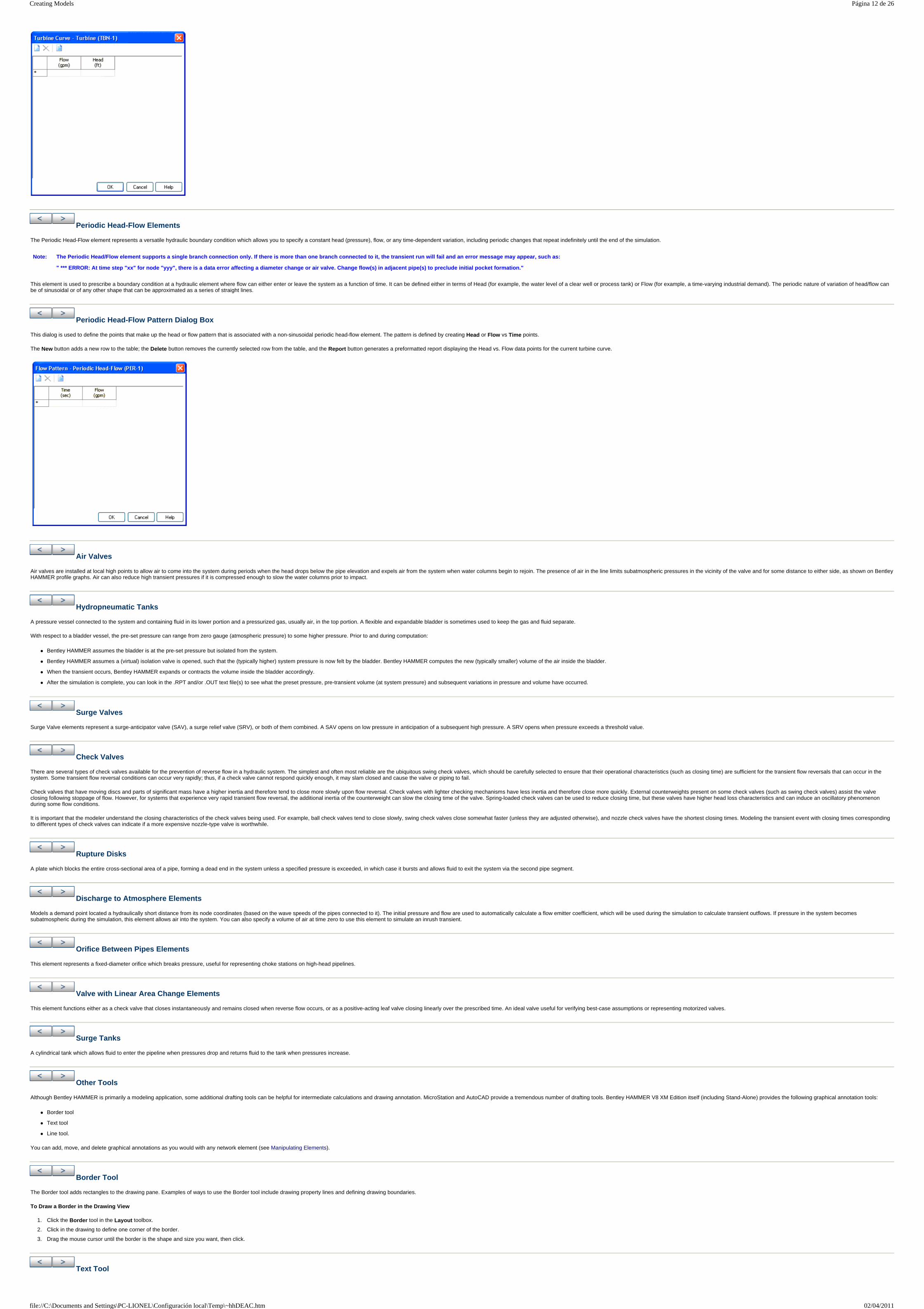
Periodic Head-Flow Elements
The Periodic Head-Flow element represents a versatile hydraulic boundary condition which allows you to specify a constant head (pressure), flow, or any time-dependent variation, including periodic changes that repeat indefinitely until the end of the simulation.
This element is used to prescribe a boundary condition at a hydraulic element where flow can either enter or leave the system as a function of time. It can be defined either in terms of Head (for example, the water level of a clear well or process tank) or Flow (for example, a time-varying industrial demand). The periodic nature of variation of head/flow can be of sinusoidal or of any other shape that can be approximated as a series of straight lines.
Periodic Head-Flow Pattern Dialog Box
This dialog is used to define the points that make up the head or flow pattern that is associated with a non-sinusoidal periodic head-flow element. The pattern is defined by creating Head or Flow vs Time points.
The New button adds a new row to the table; the Delete button removes the currently selected row from the table, and the Report button generates a preformatted report displaying the Head vs. Flow data points for the current turbine curve.
Air Valves
Air valves are installed at local high points to allow air to come into the system during periods when the head drops below the pipe elevation and expels air from the system when water columns begin to rejoin. The presence of air in the line limits subatmospheric pressures in the vicinity of the valve and for some distance to either side, as shown on Bentley HAMMER profile graphs. Air can also reduce high transient pressures if it is compressed enough to slow the water columns prior to impact.
Hydropneumatic Tanks
A pressure vessel connected to the system and containing fluid in its lower portion and a pressurized gas, usually air, in the top portion. A flexible and expandable bladder is sometimes used to keep the gas and fluid separate.
With respect to a bladder vessel, the pre-set pressure can range from zero gauge (atmospheric pressure) to some higher pressure. Prior to and during computation:
Bentley HAMMER assumes the bladder is at the pre-set pressure but isolated from the system.
Bentley HAMMER assumes a (virtual) isolation valve is opened, such that the (typically higher) system pressure is now felt by the bladder. Bentley HAMMER computes the new (typically smaller) volume of the air inside the bladder.
When the transient occurs, Bentley HAMMER expands or contracts the volume inside the bladder accordingly.
After the simulation is complete, you can look in the .RPT and/or .OUT text file(s) to see what the preset pressure, pre-transient volume (at system pressure) and subsequent variations in pressure and volume have occurred.
Surge Valves
Surge Valve elements represent a surge-anticipator valve (SAV), a surge relief valve (SRV), or both of them combined. A SAV opens on low pressure in anticipation of a subsequent high pressure. A SRV opens when pressure exceeds a threshold value.
Check Valves
There are several types of check valves available for the prevention of reverse flow in a hydraulic system. The simplest and often most reliable are the ubiquitous swing check valves, which should be carefully selected to ensure that their operational characteristics (such as closing time) are sufficient for the transient flow reversals that can occur in the system. Some transient flow reversal conditions can occur very rapidly; thus, if a check valve cannot respond quickly enough, it may slam closed and cause the valve or piping to fail.
Check valves that have moving discs and parts of significant mass have a higher inertia and therefore tend to close more slowly upon flow reversal. Check valves with lighter checking mechanisms have less inertia and therefore close more quickly. External counterweights present on some check valves (such as swing check valves) assist the valve closing following stoppage of flow. However, for systems that experience very rapid transient flow reversal, the additional inertia of the counterweight can slow the closing time of the valve. Spring-loaded check valves can be used to reduce closing time, but these valves have higher head loss characteristics and can induce an oscillatory phenomenon during some flow conditions.
It is important that the modeler understand the closing characteristics of the check valves being used. For example, ball check valves tend to close slowly, swing check valves close somewhat faster (unless they are adjusted otherwise), and nozzle check valves have the shortest closing times. Modeling the transient event with closing times corresponding to different types of check valves can indicate if a more expensive nozzle-type valve is worthwhile.
Rupture Disks
A plate which blocks the entire cross-sectional area of a pipe, forming a dead end in the system unless a specified pressure is exceeded, in which case it bursts and allows fluid to exit the system via the second pipe segment.
Discharge to Atmosphere Elements
Models a demand point located a hydraulically short distance from its node coordinates (based on the wave speeds of the pipes connected to it). The initial pressure and flow are used to automatically calculate a flow emitter coefficient, which will be used during the simulation to calculate transient outflows. If pressure in the system becomes subatmospheric during the simulation, this element allows air into the system. You can also specify a volume of air at time zero to use this element to simulate an inrush transient.
Orifice Between Pipes Elements
This element represents a fixed-diameter orifice which breaks pressure, useful for representing choke stations on high-head pipelines.
Valve with Linear Area Change Elements
This element functions either as a check valve that closes instantaneously and remains closed when reverse flow occurs, or as a positive-acting leaf valve closing linearly over the prescribed time. An ideal valve useful for verifying best-case assumptions or representing motorized valves.
Surge Tanks
A cylindrical tank which allows fluid to enter the pipeline when pressures drop and returns fluid to the tank when pressures increase.
Other Tools
Although Bentley HAMMER is primarily a modeling application, some additional drafting tools can be helpful for intermediate calculations and drawing annotation. MicroStation and AutoCAD provide a tremendous number of drafting tools. Bentley HAMMER V8 XM Edition itself (including Stand-Alone) provides the following graphical annotation tools:
Border tool
Text tool
Line tool.
You can add, move, and delete graphical annotations as you would with any network element (see Manipulating Elements).
Border Tool
The Border tool adds rectangles to the drawing pane. Examples of ways to use the Border tool include drawing property lines and defining drawing boundaries.
To Draw a Border in the Drawing View
1. Click the Border tool in the Layout toolbox.
2. Click in the drawing to define one corner of the border.
3. Drag the mouse cursor until the border is the shape and size you want, then click.
Text Tool
Note: The Periodic Head/Flow element supports a single branch connection only. If there is more than one branch connected to it, the transient run will fail and an error message may appear, such as:
" *** ERROR: At time step "xx" for node "yyy", there is a data error affecting a diameter change or air valve. Change flow(s) in adjacent pipe(s) to preclude initial pocket formation."
Página 12 de 26Creating Models
02/04/2011file://C:\Documents and Settings\PC-LIONEL\Configuración local\Temp\~hhDEAC.htm

The text tool adds text to the drawing pane. Examples of ways to use the Text tool include adding explanatory notes, titles, or labels for non-network elements. The size of the text in the drawing view is the same as the size of labels and annotations. You can define the size of text, labels, and annotation in the Drawing tab of the Tools > Options dialog.
To Add Text to the Drawing View
1. Click the Text tool in the Layout toolbox.
2. Click in the drawing to define where the text should appear.
3. In the Text Editor dialog, type the text as it should appear in the drawing view, then click OK. Note that text will be in a single line (no carriage returns allowed). To add multiple lines of text, add each line separately with the Text tool.
To Rotate Existing Text in the Drawing View
1. Click the Select tool in the Layout toolbox.
2. Right-click the text and select the Rotate command.
3. Move the mouse up or down to define the angle of the text, then click when done.
To Edit Existing Text in the Drawing View
1. Click the Select tool in the Layout toolbox.
2. Right-click the text and select the Edit Text command.
3. Make the desired changes in the Text Editor dialog that appears, then click OK.
Line Tool
The Line tool is used to add lines and polylines (multi segmented lines) to the drawing pane. Bentley HAMMER V8 XM Edition can calculate the area inside a closed polyline. Examples of ways to use the Line tool include drawing roads or catchment outlines.
To Draw a Line or Polyline in the Drawing View
1. Click the Line tool in the Layout toolbox.
2. Click in the drawing to define where the line should begin.
3. Drag the mouse cursor and click to place the line, or to place a bend if you are drawing a polyline.
4. Continue placing bends until the line is complete, then right-click and select Done.
To Close an Existing Polyline in the Drawing View
1. Click the Select tool in the Layout toolbox.
2. Right-click the polyline and select the Close command.
To Calculate the Area of a Closed Polyline
1. Click the Select tool in the Layout toolbox.
2. Right-click the polyline and select the Enclosed Area command.
To Add a Bend to an Existing Line or Polyline
1. Click the Select tool in the Layout toolbox.
2. Right-click at the location along the line or polyline where the bend should be placed and select the Bend > Add Bend command.
To Remove Bends from an Existing Line or Polyline
1. Click the Select tool in the Layout toolbox.
2. Right-click the bend to be removed and select the Bend > Remove Bend command. To remove all of the bends from a polyline (not a closed polyline), right-click the polyline and select the Bend > Remove All Bends command.
3. Bentley HAMMERBentley HAMMERTank: Modeled as a Surge Tank. The tank's Orifice Diameter value is entered as the diameter of the largest of the pipes connected to the tank.
Adding Elements to Your Model
Bentley HAMMER provides several ways to add elements to your model. They include:
Adding individual elements
Adding elements using the layout tool
Replacing an element with another element.
To add individual elements to your model
1. Click an element symbol on the Layout toolbar. The mouse cursor changes to the element symbol you selected.
2. Click in the drawing pane to add the element to your model.
3. Click again to add another element of the same type to your model.
4. To add a different element, click on the desired element symbol in the Layout toolbar, then click in the drawing pane.
5. To stop adding elements, right-click in the drawing pane to display a shortcut menu, then click Done.
To add elements using the layout tool
The layout tool is used to quickly add new elements to your model without having to select a new element button on the Layout toolbar. When the layout tool is active, you can right-click in the drawing pane to select different elements and pipes to add to the model.
1. Click the Layout tool on the Layout toolbar.
2. Right-click in the drawing pane, then select the type of element you want to add from the shortcut menu. The shortcut menu displays only those element types that are compatible with your pipe selection.
3. Click in the drawing pane to add the element.
4. Click again to add another of the same element type. The elements you add will automatically be connected by pipes.
5. To change the element, right-click and select a different element from the shortcut menu.
6. To stop adding elements using the Layout tool, right-click anywhere in the drawing pane and click Done.
Manipulating Elements
You can manipulate elements in your model in any one of the following ways:
Select elements—Manually select individual elements, manually select multiple elements, select all elements, or select all elements of a single element type
Move elements—Move elements in the drawing pane.
Delete elements—Remove elements from the model.
Split pipes—Split an existing pipe into two new pipes by adding a new node element along the exisiting pipe.
Reconnect pipes—Disconnect an exisiting pipe from an existing node element and attach it to another existing node element.
Select Elements
The following element selection options are available:
To manually select an element
Click the element. Selected elements appear in red.
To manually select multiple elements
Click the first element, then click additional elements while holding down Shift or Ctrl.
To select elements by drawing a polygon
1. Select Edit > Select By Polygon.
2. Click in the drawing pane near the elements you want to select, then drag the mouse to draw the first side of the polygon.
3. Click again to finish drawing the first side of the polygon and drag the mouse to begin drawing the next side of the polygon.
4. Repeat step 3 until the polygon is complete, then right-click and select Done.
To select all elements
To select all of the elements in your model, select Edit > Select All.
To select all elements of the same type
To select all elements of the same type (for example, all junction chambers), select Edit > Select by Element, then click the desired element type.
All elements of the selected type appear in red, including connecting pipes.
To clear selected elements
Click the Select tool then click any blank space in the drawing pane.
or
Click Edit > Clear Selection.
or
Press the Esc key.
You can also clear a selected element by clicking a different element.
To move an element in the model
1. Click the Select tool on the Layout toolbar.
2. Select the element(s) you want to move, then drag it to its new location. Pipe connections move with the element.
To delete an element
Select the element, then press Delete.
Note: You can change the selection color in the Options dialog box, which is accessible by selecting Tools > Options.
Página 13 de 26Creating Models
02/04/2011file://C:\Documents and Settings\PC-LIONEL\Configuración local\Temp\~hhDEAC.htm
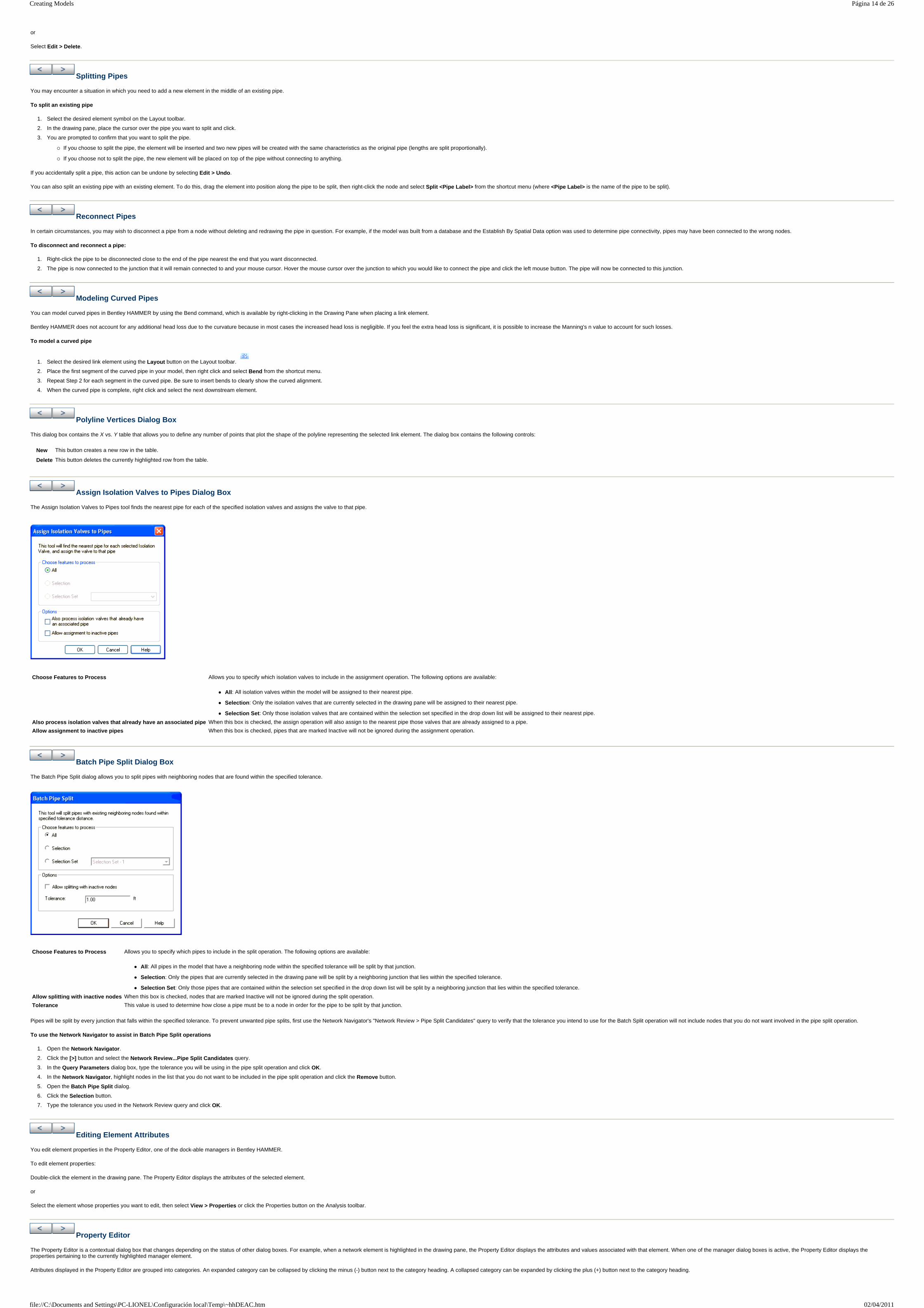
or
Select Edit > Delete.
Splitting Pipes
You may encounter a situation in which you need to add a new element in the middle of an existing pipe.
To split an existing pipe
1. Select the desired element symbol on the Layout toolbar.
2. In the drawing pane, place the cursor over the pipe you want to split and click.
3. You are prompted to confirm that you want to split the pipe.
If you choose to split the pipe, the element will be inserted and two new pipes will be created with the same characteristics as the original pipe (lengths are split proportionally).
If you choose not to split the pipe, the new element will be placed on top of the pipe without connecting to anything.
If you accidentally split a pipe, this action can be undone by selecting Edit > Undo.
You can also split an existing pipe with an existing element. To do this, drag the element into position along the pipe to be split, then right-click the node and select Split <Pipe Label> from the shortcut menu (where <Pipe Label> is the name of the pipe to be split).
Reconnect Pipes
In certain circumstances, you may wish to disconnect a pipe from a node without deleting and redrawing the pipe in question. For example, if the model was built from a database and the Establish By Spatial Data option was used to determine pipe connectivity, pipes may have been connected to the wrong nodes.
To disconnect and reconnect a pipe:
1. Right-click the pipe to be disconnected close to the end of the pipe nearest the end that you want disconnected.
2. The pipe is now connected to the junction that it will remain connected to and your mouse cursor. Hover the mouse cursor over the junction to which you would like to connect the pipe and click the left mouse button. The pipe will now be connected to this junction.
Modeling Curved Pipes
You can model curved pipes in Bentley HAMMER by using the Bend command, which is available by right-clicking in the Drawing Pane when placing a link element.
Bentley HAMMER does not account for any additional head loss due to the curvature because in most cases the increased head loss is negligible. If you feel the extra head loss is significant, it is possible to increase the Manning's n value to account for such losses.
To model a curved pipe
1. Select the desired link element using the Layout button on the Layout toolbar.
2. Place the first segment of the curved pipe in your model, then right click and select Bend from the shortcut menu.
3. Repeat Step 2 for each segment in the curved pipe. Be sure to insert bends to clearly show the curved alignment.
4. When the curved pipe is complete, right click and select the next downstream element.
Polyline Vertices Dialog Box
This dialog box contains the X vs. Y table that allows you to define any number of points that plot the shape of the polyline representing the selected link element. The dialog box contains the following controls:
Assign Isolation Valves to Pipes Dialog Box
The Assign Isolation Valves to Pipes tool finds the nearest pipe for each of the specified isolation valves and assigns the valve to that pipe.
Batch Pipe Split Dialog Box
The Batch Pipe Split dialog allows you to split pipes with neighboring nodes that are found within the specified tolerance.
Pipes will be split by every junction that falls within the specified tolerance. To prevent unwanted pipe splits, first use the Network Navigator's "Network Review > Pipe Split Candidates" query to verify that the tolerance you intend to use for the Batch Split operation will not include nodes that you do not want involved in the pipe split operation.
To use the Network Navigator to assist in Batch Pipe Split operations
1. Open the Network Navigator.
2. Click the [>] button and select the Network Review...Pipe Split Candidates query.
3. In the Query Parameters dialog box, type the tolerance you will be using in the pipe split operation and click OK.
4. In the Network Navigator, highlight nodes in the list that you do not want to be included in the pipe split operation and click the Remove button.
5. Open the Batch Pipe Split dialog.
6. Click the Selection button.
7. Type the tolerance you used in the Network Review query and click OK.
Editing Element Attributes
You edit element properties in the Property Editor, one of the dock-able managers in Bentley HAMMER.
To edit element properties:
Double-click the element in the drawing pane. The Property Editor displays the attributes of the selected element.
or
Select the element whose properties you want to edit, then select View > Properties or click the Properties button on the Analysis toolbar.
Property Editor
The Property Editor is a contextual dialog box that changes depending on the status of other dialog boxes. For example, when a network element is highlighted in the drawing pane, the Property Editor displays the attributes and values associated with that element. When one of the manager dialog boxes is active, the Property Editor displays the properties pertaining to the currently highlighted manager element.
Attributes displayed in the Property Editor are grouped into categories. An expanded category can be collapsed by clicking the minus (-) button next to the category heading. A collapsed category can be expanded by clicking the plus (+) button next to the category heading.
New This button creates a new row in the table.
Delete This button deletes the currently highlighted row from the table.
Choose Features to Process Allows you to specify which isolation valves to include in the assignment operation. The following options are available:
All: All isolation valves within the model will be assigned to their nearest pipe.
Selection: Only the isolation valves that are currently selected in the drawing pane will be assigned to their nearest pipe.
Selection Set: Only those isolation valves that are contained within the selection set specified in the drop down list will be assigned to their nearest pipe.
Also process isolation valves that already have an associated pipe When this box is checked, the assign operation will also assign to the nearest pipe those valves that are already assigned to a pipe.
Allow assignment to inactive pipes When this box is checked, pipes that are marked Inactive will not be ignored during the assignment operation.
Choose Features to Process Allows you to specify which pipes to include in the split operation. The following options are available:
All: All pipes in the model that have a neighboring node within the specified tolerance will be split by that junction.
Selection: Only the pipes that are currently selected in the drawing pane will be split by a neighboring junction that lies within the specified tolerance.
Selection Set: Only those pipes that are contained within the selection set specified in the drop down list will be split by a neighboring junction that lies within the specified tolerance.
Allow splitting with inactive nodes When this box is checked, nodes that are marked Inactive will not be ignored during the split operation.
Tolerance This value is used to determine how close a pipe must be to a node in order for the pipe to be split by that junction.
Página 14 de 26Creating Models
02/04/2011file://C:\Documents and Settings\PC-LIONEL\Configuración local\Temp\~hhDEAC.htm

For the most efficient data entry in Text Box style fields, instead of clicking on the Field, click on the label to the left of the field you want to edit, and start typing. Press Enter to commit the value, then use the Up/Down keyboard arrows to navigate to the next field you want to edit. You can then edit the field data without clicking the label first; when you are finished editing the field data, press the Enter key, and proceed to the next field using the arrow keys, and so on.
Find Element
The top section of the Property Editor contains the Find Element tool. The Find Element tool is used to:
Quickly find a recently-created or added element in your model. The Element menu contains a list of the most recently-created and added elements. Click an element in the Element menu to center the drawing pane around that element and highlight it.
Find an element in your model by typing the element label or ID in the Element menu then clicking the Find button or pressing Enter. The drawing pane centers around the highlighted element.
Find all elements of a certain type by using an asterisk (*) as a wild-card character. For example, if you want to find all of the pipes in your model, you type co* (this is not case-sensitive) then click the Find button. The drawing pane centers around and highlights the first instance of a pipe in your model, and lists all pipes in your model in the Element menu. For more information about using wildcards, see Using the Like Operator.
* and # are wildcard characters. If the element(s) you are looking for contains one or more of those characters, you will need to enclose the search term in brackets: [ and ].
If Find returns multiple results then Network Navigator automatically opens.
The following controls are included:
Labeling Elements
When elements are placed, they are assigned a default label. You can define the default label using the Labeling tab of the Tools > Options dialog.
You can also relabel elements that have already been placed using the Relabel command in the element FlexTables.
Relabeling Elements
You can relabel elements from within the Property Editor.
To relabel an element
1. Select the element in the Drawing Pane then, if the Property Editor is not already displayed, select View > Properties.
2. In the General section of the Property Editor, click in the Label field, then type a new label for the element.
Set Field Options Dialog Box
The Set Field Options dialog box is used to set the units for a specific attribute without affecting the units used by other attributes or globally.
To use the Set Field Options dialog box, right-click any numerical field that has units, then select Units and Formatting.
Using Named Views
The Named View dialog box is where you can store the current views X and Y coordinates. When you set a view in the drawing pane and add a named view, the current view is saved as the named view. You can then center the drawing pane on the named view with the Go To View command.
Choose View > Named Views to open the Named View dialog box.
The toolbar contains the following controls:
Using Selection Sets
Selection sets are user-defined groups of network elements. They allow you to predefine a group of network elements that you want to manipulate together. You manage selection sets in the Selection Sets Manager.
Bentley HAMMER contains powerful features that let you view or analyze subsets of your entire model. You can find these elements using the Network Navigator (see Using the Network Navigator). The Network Navigator is used to choose a selection set, then view the list of elements in the selection set or find individual elements from the selection set in the drawing.
In order to use the Network Navigator, you must first create a selection set. There are two ways to create a selection set:
From a selection of elements—You create a new selection set in the Selection Sets Manager, then use your mouse to select the desired elements in the drawing pane.
Element Type an element label or ID in this field then click the Find button to quickly locate it in your model. The element selected in this menu will be centered in the drawing pane when the Zoom To command is initiated, at the magnification level specified by the Zoom Level menu. The drop-down menu lists recently-created or added elements, elements that are part of a selection set, and that are part of the results from a recent Find operation.
Find
Zooms the drawing pane view to the element typed or selected in the Element menu at the magnification level specified in the Zoom Level menu.
Help
Displays online help for the Property Editor.
Zoom Level Specifies the magnification level at which elements are displayed in the drawing pane when the Zoom To command is initiated.
Categorized
Displays the fields in the Property Editor in categories. This is the default.
Alphabetic
Displays the fields in the Property Editor in alphabetical order.
Property Pages
Displays the property pages.
Definition bar The space at the bottom of the Properties editor is where the selected field is defined.
Value Displays the value of the currently selected item.
Unit Displays the type of measurement. To change the unit, select the unit you want to use from the drop-down list. With this option you can use both U.S. customary and S.I. units in the same worksheet.
Display Precision
Sets the rounding of numbers and number of digits displayed after the decimal point. Enter a negative number for rounding to the nearest power of 10: (-1) rounds to 10, (-2) rounds to 100, (-3) rounds to 1000, and so on. Enter a number from 0 to 15 to indicate the number of digits after the decimal point.
Format Selects the display format used by the current field. Choices include:
Scientific—Converts the entered value to a string of the form "-d.ddd...E+ddd" or "-d.ddd...e+ddd", where each 'd' indicates a digit (0-9). The string starts with a minus sign if the number is negative.
Fixed Point—Abides by the display precision setting and automatically enters zeros after the decimal place to do so. With a display precision of 3, an entered value of 3.5 displays as 3.500.
General—Truncates any zeros after the decimal point, regardless of the display precision value. With a display precision of 3, the value that would appear as 5.200 in Fixed Point format displays as 5.2 when using General format. The number is also rounded. So, an entered value of 5.35 displays as 5.4 regardless of the display precision.
Number—Converts the entered value to a string of the form "-d,ddd,ddd.ddd...", where each 'd' indicates a digit (0-9). The string starts with a minus sign if the number is negative. Thousand separators are inserted between each group of three digits to the left of the decimal point.
New
Contains the following commands:
Named View—Opens a Named View Properties box to create a new named view.
Folder—Opens a Named Views Folder Properties box to enter a label for the new folder.
Delete
Deletes the named view or folder that is currently selected.
Rename
Rename the currently selected named view or folder.
Go to View
Centers the drawing pane on the named view.
Shift Up and Shift Down
Moves the selected named view or folder up or down.
Expand All or Collapse All
Expands or collapses the named views and folders.
Help
Displays online help for Named Views.
Página 15 de 26Creating Models
02/04/2011file://C:\Documents and Settings\PC-LIONEL\Configuración local\Temp\~hhDEAC.htm
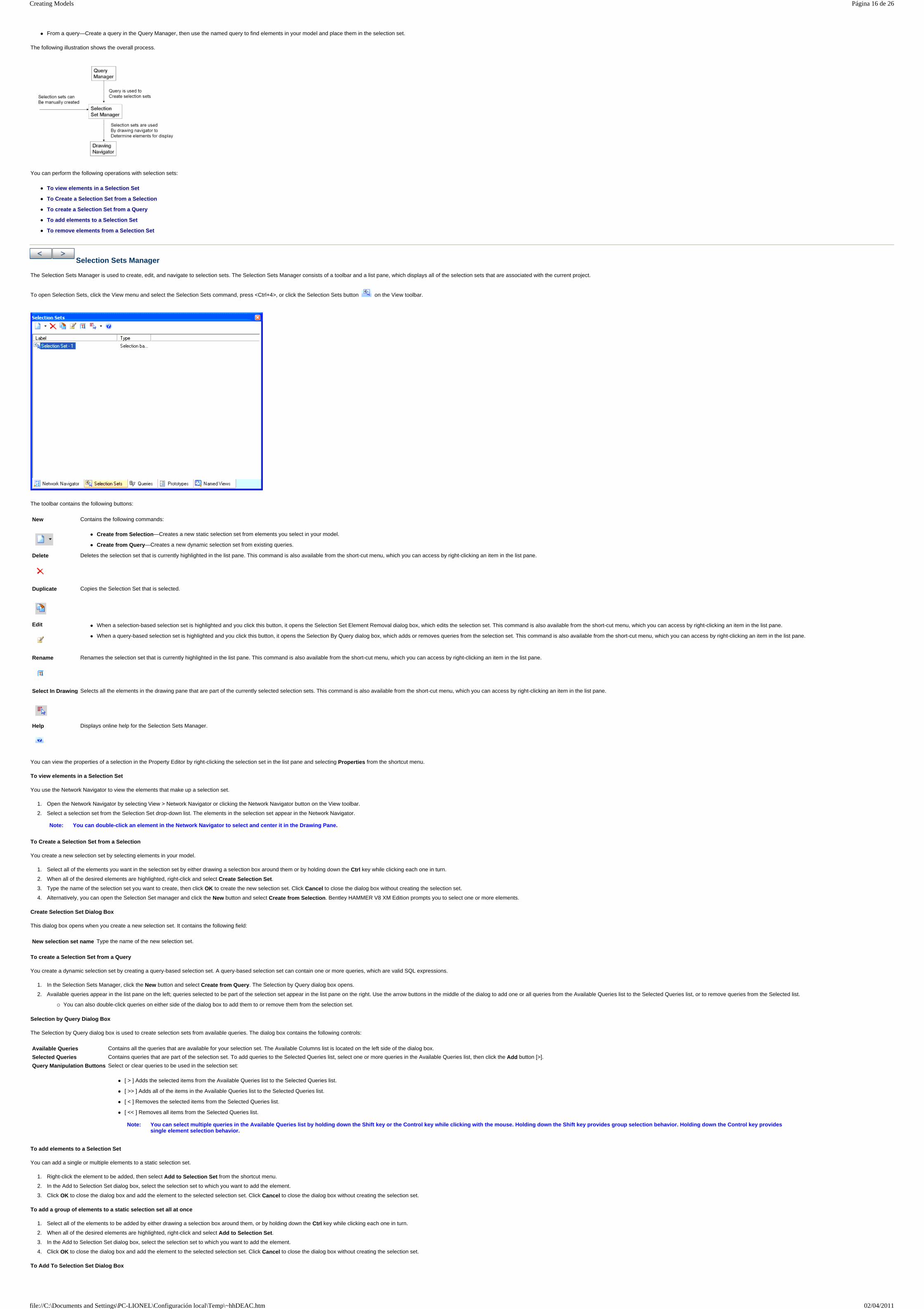
From a query—Create a query in the Query Manager, then use the named query to find elements in your model and place them in the selection set.
The following illustration shows the overall process.
You can perform the following operations with selection sets:
To view elements in a Selection Set
To Create a Selection Set from a Selection
To create a Selection Set from a Query
To add elements to a Selection Set
To remove elements from a Selection Set
Selection Sets Manager
The Selection Sets Manager is used to create, edit, and navigate to selection sets. The Selection Sets Manager consists of a toolbar and a list pane, which displays all of the selection sets that are associated with the current project.
To open Selection Sets, click the View menu and select the Selection Sets command, press <Ctrl+4>, or click the Selection Sets button on the View toolbar.
The toolbar contains the following buttons:
You can view the properties of a selection in the Property Editor by right-clicking the selection set in the list pane and selecting Properties from the shortcut menu.
To view elements in a Selection Set
You use the Network Navigator to view the elements that make up a selection set.
1. Open the Network Navigator by selecting View > Network Navigator or clicking the Network Navigator button on the View toolbar.
2. Select a selection set from the Selection Set drop-down list. The elements in the selection set appear in the Network Navigator.
To Create a Selection Set from a Selection
You create a new selection set by selecting elements in your model.
1. Select all of the elements you want in the selection set by either drawing a selection box around them or by holding down the Ctrl key while clicking each one in turn.
2. When all of the desired elements are highlighted, right-click and select Create Selection Set.
3. Type the name of the selection set you want to create, then click OK to create the new selection set. Click Cancel to close the dialog box without creating the selection set.
4. Alternatively, you can open the Selection Set manager and click the New button and select Create from Selection. Bentley HAMMER V8 XM Edition prompts you to select one or more elements.
Create Selection Set Dialog Box
This dialog box opens when you create a new selection set. It contains the following field:
To create a Selection Set from a Query
You create a dynamic selection set by creating a query-based selection set. A query-based selection set can contain one or more queries, which are valid SQL expressions.
1. In the Selection Sets Manager, click the New button and select Create from Query. The Selection by Query dialog box opens.
2. Available queries appear in the list pane on the left; queries selected to be part of the selection set appear in the list pane on the right. Use the arrow buttons in the middle of the dialog to add one or all queries from the Available Queries list to the Selected Queries list, or to remove queries from the Selected list.
You can also double-click queries on either side of the dialog box to add them to or remove them from the selection set.
Selection by Query Dialog Box
The Selection by Query dialog box is used to create selection sets from available queries. The dialog box contains the following controls:
To add elements to a Selection Set
You can add a single or multiple elements to a static selection set.
1. Right-click the element to be added, then select Add to Selection Set from the shortcut menu.
2. In the Add to Selection Set dialog box, select the selection set to which you want to add the element.
3. Click OK to close the dialog box and add the element to the selected selection set. Click Cancel to close the dialog box without creating the selection set.
To add a group of elements to a static selection set all at once
1. Select all of the elements to be added by either drawing a selection box around them, or by holding down the Ctrl key while clicking each one in turn.
2. When all of the desired elements are highlighted, right-click and select Add to Selection Set.
3. In the Add to Selection Set dialog box, select the selection set to which you want to add the element.
4. Click OK to close the dialog box and add the element to the selected selection set. Click Cancel to close the dialog box without creating the selection set.
To Add To Selection Set Dialog Box
New
Contains the following commands:
Create from Selection—Creates a new static selection set from elements you select in your model.
Create from Query—Creates a new dynamic selection set from existing queries.
Delete
Deletes the selection set that is currently highlighted in the list pane. This command is also available from the short-cut menu, which you can access by right-clicking an item in the list pane.
Duplicate
Copies the Selection Set that is selected.
Edit
When a selection-based selection set is highlighted and you click this button, it opens the Selection Set Element Removal dialog box, which edits the selection set. This command is also available from the short-cut menu, which you can access by right-clicking an item in the list pane.
When a query-based selection set is highlighted and you click this button, it opens the Selection By Query dialog box, which adds or removes queries from the selection set. This command is also available from the short-cut menu, which you can access by right-clicking an item in the list pane.
Rename
Renames the selection set that is currently highlighted in the list pane. This command is also available from the short-cut menu, which you can access by right-clicking an item in the list pane.
Select In Drawing
Selects all the elements in the drawing pane that are part of the currently selected selection sets. This command is also available from the short-cut menu, which you can access by right-clicking an item in the list pane.
Help
Displays online help for the Selection Sets Manager.
Note: You can double-click an element in the Network Navigator to select and center it in the Drawing Pane.
New selection set name Type the name of the new selection set.
Available Queries Contains all the queries that are available for your selection set. The Available Columns list is located on the left side of the dialog box.
Selected Queries Contains queries that are part of the selection set. To add queries to the Selected Queries list, select one or more queries in the Available Queries list, then click the Add button [>].
Query Manipulation Buttons Select or clear queries to be used in the selection set:
[ > ] Adds the selected items from the Available Queries list to the Selected Queries list.
[ >> ] Adds all of the items in the Available Queries list to the Selected Queries list.
[ < ] Removes the selected items from the Selected Queries list.
[ << ] Removes all items from the Selected Queries list.
Note: You can select multiple queries in the Available Queries list by holding down the Shift key or the Control key while clicking with the mouse. Holding down the Shift key provides group selection behavior. Holding down the Control key provides single element selection behavior.
Página 16 de 26Creating Models
02/04/2011file://C:\Documents and Settings\PC-LIONEL\Configuración local\Temp\~hhDEAC.htm

This dialog box opens when you select the Add to Selection Set command. It contains the following field:
To remove elements from a Selection Set
You can easily remove elements from a static selection set in the Selection Set Element Removal dialog box.
1. Display the Selection Sets Manager by selecting View > Selection Sets or clicking the Selection Sets button on the View toolbar.
2. In the Selection Sets Manager, select the desired selection set then click the Edit button.
3. In the Selection Set Element Removal dialog box, find the element you want to remove in the table. Select the element label or the entire table row, then click the Delete button.
4. Click OK.
Selection Set Element Removal Dialog Box
This dialog opens when you click the edit button from the Selection Sets manager. It is used to remove elements from the selection set that is highlighted in the Selection Sets Manager when the Edit button is clicked.
Group-Level Operations on Selection Sets
You can perform group-level deletions and reporting on elements in a selection set by using the Select In Drawing button in the Selection Sets Manager.
To delete multiple elements from a selection set
1. Open the Selection Sets Manager by selecting View > Selection Sets or clicking the Selection Sets button on the View toolbar.
2. In the Selection Sets Manager, highlight the selection set that contains elements you want to delete.
3. Click the Select In Drawing button in the Selection Sets Manager to highlight all of the selection set's elements in the drawing pane.
If there is only one selection set listed in the Selection Sets manager, you don't have to highlight it before clicking the Select In Drawing button.
4. Shift-click (hold down the Shift key and click the left mouse button) any selected elements that you do not want to delete.
5. Right-click and select Delete. The highlighted elements in the selection set are deleted from your model.
To create a report on a group of elements in a selection set
1. Open the Selection Sets Manager by selecting View > Selection Sets or clicking the Selection Sets button on the View toolbar.
2. In the Selection Sets Manager, highlight the selection set that contains elements you want to report on.
3. Click the Select In Drawing button in the Selection Sets Manager to highlight all of the selection set's elements in the drawing pane.
If there is only one selection set listed in the Selection Sets manager, you don't have to highlight it before clicking the Select In Drawing button.
4. Shift-click (hold down the Shift key and click the left mouse button) any selected elements that you do not want to include in the report.
5. Right-click and select Report. A report window displays the report.
Using the Network Navigator
The Network Navigator consists of a toolbar and a table that lists the Label and ID of each of the elements contained within the current selection. The selection can include elements highlighted manually in the drawing pane, elements contained within a selection set, or elements returned by a query.
To open the Network Navigator, click the View menu and select the Network Navigator command, press <Ctrl+3>, or click the Network Navigator button on the View toolbar.
The following controls are included in Network Navigator:
Predefined Queries
The Network Navigator provides access to a number of predefined queries grouped categorically, accessed by clicking the [>] button. Categories and the queries contained therein include:
Network
Network queries include "All Elements" queries for each element type, allowing you to display all elements of any type in the Network Navigator.
Network Review
Network Review Queries include the following:
Nodes In Close Proximity - Identifies nodes within a specific tolerance.
Crossing Pipes - Identifies pipes that intersect one another with no junction at the intersection.
Orphaned Nodes - Identifies nodes that are not connected to a pipe in the model.
Orphaned Isolation Valves - Identifies isolation valves that are not connected to a pipe in the model.
Dead End Nodes - Identifies nodes that are only connected to one pipe.
Dead End Junctions - Identifies junctions that are only connected to one pipe.
Pipe Split Candidates- Identifies nodes near a pipe that may be intended to be nodes along the pipe. The tolerance value can be set for the maximum distance from the pipe where the node should be considered as a pipe split candidate.
Pipes Missing Nodes - Identifies which pipes are missing either one or both end nodes.
Duplicate Pipes - Identifies instances in the model where a pipe shares both end nodes with another pipe.
Add to: Selects the selection set to which the currently highlighted element or elements will be added.
Note: While it is not possible to directly edit groups of elements in a selection set, you can use the Next button in the Network Navigator to quickly navigate through each element in the selection set and edit its properties in the Property Editor.
Query Selection List
Choose the element sets to use in the query. Once a query is selected, it can be executed when you click the > icon.
If there is already a Query listed in the list box, it can be run when the Execute icon is clicked.
Execute
Click to run the selected query.
Previous
Zooms the drawing pane view to the selected element at the magnification level specified in the Zoom Level menu.
Zoom To
Chooses the element below the currently selected one in the list.
Next
Specifies the magnification level at which elements are displayed in the drawing pane when the Zoom To command is initiated.
Copy
Copies the elements to the Windows clipboard.
Remove
Removes the selected element from the list.
Select In Drawing
Selects the listed elements in the drawing pane and performs a zoom extent based on the selection.
Highlight
When this toggle button is on, elements returned by a query will be highlighted in the drawing pane to increase their visibility.
Refresh Drawing
Refreshes the current selection.
Help
Opens Bentley HAMMER Help.
Página 17 de 26Creating Models
02/04/2011file://C:\Documents and Settings\PC-LIONEL\Configuración local\Temp\~hhDEAC.htm
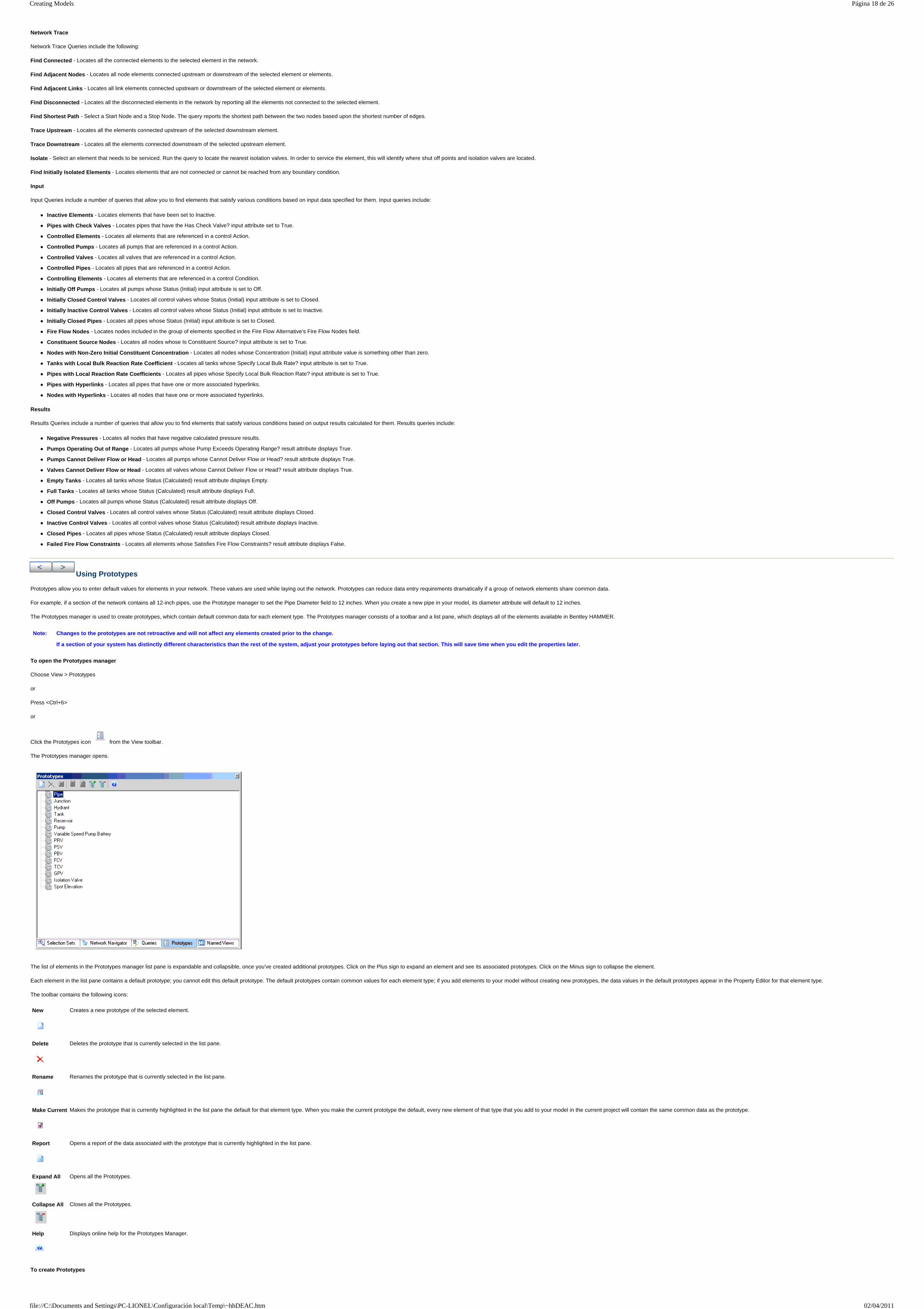
Network Trace
Network Trace Queries include the following:
Find Connected - Locates all the connected elements to the selected element in the network.
Find Adjacent Nodes - Locates all node elements connected upstream or downstream of the selected element or elements.
Find Adjacent Links - Locates all link elements connected upstream or downstream of the selected element or elements.
Find Disconnected - Locates all the disconnected elements in the network by reporting all the elements not connected to the selected element.
Find Shortest Path - Select a Start Node and a Stop Node. The query reports the shortest path between the two nodes based upon the shortest number of edges.
Trace Upstream - Locates all the elements connected upstream of the selected downstream element.
Trace Downstream - Locates all the elements connected downstream of the selected upstream element.
Isolate - Select an element that needs to be serviced. Run the query to locate the nearest isolation valves. In order to service the element, this will identify where shut off points and isolation valves are located.
Find Initially Isolated Elements - Locates elements that are not connected or cannot be reached from any boundary condition.
Input
Input Queries include a number of queries that allow you to find elements that satisfy various conditions based on input data specified for them. Input queries include:
Inactive Elements - Locates elements that have been set to Inactive.
Pipes with Check Valves - Locates pipes that have the Has Check Valve? input attribute set to True.
Controlled Elements - Locates all elements that are referenced in a control Action.
Controlled Pumps - Locates all pumps that are referenced in a control Action.
Controlled Valves - Locates all valves that are referenced in a control Action.
Controlled Pipes - Locates all pipes that are referenced in a control Action.
Controlling Elements - Locates all elements that are referenced in a control Condition.
Initially Off Pumps - Locates all pumps whose Status (Initial) input attribute is set to Off.
Initially Closed Control Valves - Locates all control valves whose Status (Initial) input attribute is set to Closed.
Initially Inactive Control Valves - Locates all control valves whose Status (Initial) input attribute is set to Inactive.
Initially Closed Pipes - Locates all pipes whose Status (Initial) input attribute is set to Closed.
Fire Flow Nodes - Locates nodes included in the group of elements specified in the Fire Flow Alternative's Fire Flow Nodes field.
Constituent Source Nodes - Locates all nodes whose Is Constituent Source? input attribute is set to True.
Nodes with Non-Zero Initial Constituent Concentration - Locates all nodes whose Concentration (Initial) input attribute value is something other than zero.
Tanks with Local Bulk Reaction Rate Coefficient - Locates all tanks whose Specify Local Bulk Rate? input attribute is set to True.
Pipes with Local Reaction Rate Coefficients - Locates all pipes whose Specify Local Bulk Reaction Rate? input attribute is set to True.
Pipes with Hyperlinks - Locates all pipes that have one or more associated hyperlinks.
Nodes with Hyperlinks - Locates all nodes that have one or more associated hyperlinks.
Results
Results Queries include a number of queries that allow you to find elements that satisfy various conditions based on output results calculated for them. Results queries include:
Negative Pressures - Locates all nodes that have negative calculated pressure results.
Pumps Operating Out of Range - Locates all pumps whose Pump Exceeds Operating Range? result attribute displays True.
Pumps Cannot Deliver Flow or Head - Locates all pumps whose Cannot Deliver Flow or Head? result attribute displays True.
Valves Cannot Deliver Flow or Head - Locates all valves whose Cannot Deliver Flow or Head? result attribute displays True.
Empty Tanks - Locates all tanks whose Status (Calculated) result attribute displays Empty.
Full Tanks - Locates all tanks whose Status (Calculated) result attribute displays Full.
Off Pumps - Locates all pumps whose Status (Calculated) result attribute displays Off.
Closed Control Valves - Locates all control valves whose Status (Calculated) result attribute displays Closed.
Inactive Control Valves - Locates all control valves whose Status (Calculated) result attribute displays Inactive.
Closed Pipes - Locates all pipes whose Status (Calculated) result attribute displays Closed.
Failed Fire Flow Constraints - Locates all elements whose Satisfies Fire Flow Constraints? result attribute displays False.
Using Prototypes
Prototypes allow you to enter default values for elements in your network. These values are used while laying out the network. Prototypes can reduce data entry requirements dramatically if a group of network elements share common data.
For example, if a section of the network contains all 12-inch pipes, use the Prototype manager to set the Pipe Diameter field to 12 inches. When you create a new pipe in your model, its diameter attribute will default to 12 inches.
The Prototypes manager is used to create prototypes, which contain default common data for each element type. The Prototypes manager consists of a toolbar and a list pane, which displays all of the elements available in Bentley HAMMER.
To open the Prototypes manager
Choose View > Prototypes
or
Press <Ctrl+6>
or
Click the Prototypes icon from the View toolbar.
The Prototypes manager opens.
The list of elements in the Prototypes manager list pane is expandable and collapsible, once you've created additional prototypes. Click on the Plus sign to expand an element and see its associated prototypes. Click on the Minus sign to collapse the element.
Each element in the list pane contains a default prototype; you cannot edit this default prototype. The default prototypes contain common values for each element type; if you add elements to your model without creating new prototypes, the data values in the default prototypes appear in the Property Editor for that element type.
The toolbar contains the following icons:
To create Prototypes
Note: Changes to the prototypes are not retroactive and will not affect any elements created prior to the change.
If a section of your system has distinctly different characteristics than the rest of the system, adjust your prototypes before laying out that section. This will save time when you edit the properties later.
New
Creates a new prototype of the selected element.
Delete
Deletes the prototype that is currently selected in the list pane.
Rename
Renames the prototype that is currently selected in the list pane.
Make Current
Makes the prototype that is currently highlighted in the list pane the default for that element type. When you make the current prototype the default, every new element of that type that you add to your model in the current project will contain the same common data as the prototype.
Report
Opens a report of the data associated with the prototype that is currently highlighted in the list pane.
Expand All
Opens all the Prototypes.
Collapse All
Closes all the Prototypes.
Help
Displays online help for the Prototypes Manager.
Página 18 de 26Creating Models
02/04/2011file://C:\Documents and Settings\PC-LIONEL\Configuración local\Temp\~hhDEAC.htm

1. Open your Bentley HAMMER project or start a new project.
2. Choose View > Prototypes or press <Ctrl+6>.
The Prototypes Manager opens.
3. Select the element type for which you want to create a prototype, then click New.
The list expands to display all the prototypes that exist for that element type.
Each element type contains a default prototype, which is not editable, and any prototypes that you have created. The current set of default values for each element type is identified by the Make Current icon.
4. Double-click the prototype you just created. The Property Editor for the element type opens.
5. Edit the attribute values in the Property Editor as required.
6. To make the new prototype the default, click the Make Current button in the Prototypes Manager.
The icon next to the prototype changes to indicate that the values in the prototype will be applied to all new elements of that type that you add to your current project.
7. Perform the following optional steps:
To rename a prototype, select the prototype in the list and click the Rename button.
To delete a prototype, select the prototype in the list and click the Delete button.
To view a report of the default values in the prototype, select the prototype in the list and click the Report button.
Zones
The Zones manager allows you to manipulate zones quickly and easily. Zones listed in the Zones manager can be associated with each nodal element using the Element Editors, Prototypes, or FlexTables. This manager includes a list of all of the available zones and a toolbar.
To open the Zones manager
Choose Components > Zones
or
Click the Zones icon from the Components toolbar.
The Zones manager opens.
The toolbar contains the following icons:
New—Adds a new zone to the zone list.
Duplicate—Creates a copy of an existing zone.
Delete—Deletes an existing zone.
Rename - Renames the selected zone.
Notes - Enter information about the zone.
Engineering Libraries
Engineering Libraries are powerful and flexible tools that you use to manage specifications of common materials, objects, or components that are shared across projects. Some examples of objects that are specified through engineering libraries include constituents, pipe materials, patterns, and pump definitions.
You can modify engineering libraries and the items they contain by using the Engineering Libraries command in the Components menu.
You work with engineering libraries and the items they contain in the Engineering Libraries dialog box, which contains all of the project's engineering libraries. Individual libraries are compilations of library entries along with their attributes.
By default, each project you create in Bentley HAMMER uses the items in the default libraries. In special circumstances, you may wish to create custom libraries to use with one or more projects. You can do this by copying a standard library or creating a new library.
When you change the properties for an item in an engineering library, those changes affect all projects that use that library item. At the time a project is loaded, all of its engineering library items are synchronized to the current library. Items are synchronized based on their label. If the label is the same, then the item's values will be made the same.
The default libraries that are installed with Bentley HAMMER V8 XM Edition are editable. In addition, you can create a new library of any type and can then create new entries of your own definition.
Library types are displayed in the Engineering Library manager in an expanding/collapsing tree view.
Library types can contain categories and subcategories, represented as folders in the tree view.
Individual library entries are contained within the categories, subcategories, and folders in the tree view.
Libraries, categories, folders, and library entries are displayed in the tree view with their own unique icons. You can right-click these icons to display submenus with different commands.
Working with Engineering Libraries
When you select a library entry in the tree view, the attributes and attribute values associated with the entry are displayed in the editor pane on the right side of the dialog box.
Right-clicking a Library icon in the tree view opens a shortcut menu containing the following commands:
Working with Categories
Right-clicking a Category icon in the tree view opens a shortcut menu containing the following commands:
Working with Folders
Right-clicking a Folder icon in the tree view opens a shortcut menu containing the following commands:
Note: The data for each engineering library is stored in an XML file in your Bentley HAMMER V8 XM Edition program directory. We strongly recommend that you edit these files only using the built-in tools available by selecting Tools > Engineering Libraries.
Create Library Creates a new engineering library of the currently highlighted type.
Add Existing Library Adds an existing engineering library that has been stored on your hard drive as an .xml file to the current project.
Add Item Creates a new entry within the current library.
Add Folder Creates a new folder under the currently highlighted library.
Save As Saves the currently highlighted category as an .xml file that can then be used in future projects.
Remove Deletes the currently highlighted category from the library.
Add Item Creates a new entry within the current folder.
Add Folder Creates a new folder under the currently highlighted folder.
Rename Renames the currently highlighted folder.
Delete Deletes the currently highlighted folder and its contents.
Página 19 de 26Creating Models
02/04/2011file://C:\Documents and Settings\PC-LIONEL\Configuración local\Temp\~hhDEAC.htm

Working with Library Entries
Right-clicking a Library Entry icon in the tree view opens a shortcut menu containing the following commands:
Engineering Libraries Dialog Box
The Engineering Libraries dialog box contains an explorer tree-view pane on the left, a library entry editor pane on the right, and the following icons above the explorer tree view pane:
Sharing Engineering Libraries On a Network
You can share engineering libraries with other Bentley HAMMER users in your organization by storing the engineering libraries on a network drive. All users who will have access to the shared engineering library should have read-write access to the network folder in which the library is located.
To share an engineering library on a network, open the Engineering Libraries in Bentley HAMMER and create a new library in a network folder to which all users have read-write access.
Hyperlinks
The Hyperlinks feature is used to associate external files, such as pictures or movie files, with elements. You can Add, Edit, Delete, and Launch hyperlinks from the Hyperlinks manager.
To use hyperlinks, choose Tools > Hyperlinks. The Hyperlinks dialog box opens. The dialog box contains a toolbar and a tabular view of all your hyperlinks.
The toolbar contains the following icons:
The table contains the following columns:
Once you have created Hyperlinks, you can open the Hyperlinks dialog box from within a Property dialog box associated with that Hyperlink.
Click the ellipsis (...) in the Hyperlinks field and the Hyperlinks dialog box opens.
Add Hyperlink Dialog Box
New hyperlinks are created in this dialog box.
The Add Hyperlinks dialog box has the following controls:
Edit Hyperlink Dialog Box
You edit existing hyperlinks in the Edit Hyperlink dialog box.
The Edit Hyperlinks dialog box contains the following controls:
Rename Renames the currently highlighted entry.
Delete Deletes the currently highlighted entry from the library.
New
Opens a submenu containing the following commands:
Create Library—Creates a new engineering library.
Add Existing Library—Adds an existing engineering library that has been stored on your hard drive as an .xml file to the current project.
Delete
Removes the currently highlighted engineering library from the current project.
Rename
Renames the currently highlighted engineering library.
New
Creates a new hyperlink. Opens the Add Hyperlink dialog box.
Delete
Deletes the currently selected hyperlink.
Edit
Edits the currently selected hyperlink. Opens the Edit Hyperlink dialog box.
Launch
Launches the external file associated with the currently selected hyperlink.
Element Type Displays the element type of the element associated with the hyperlink.
Element Displays the label of the element associated with the hyperlink.
Link Displays the complete path of the hyperlink.
Description Displays a description of the hyperlink, which you can optionally enter when you create or edit the hyperlink.
Element Type Select an element type from the drop-down list.
Element Select an element from the drop-down list of specific elements from the model. Or click the ellipsis to select an element from the drawing.
Link Click the ellipsis (...) to browse your computer and locate the file to be associated with the hyperlink. You can also enter the path of the external file by typing it in the Link field.
Description Create a description of the hyperlink.
Link Defines the complete path of the external file associated with the selected hyperlink. You can type the path yourself or click the ellipsis (...) to search your computer for the file. Once you have selected the file, you can test the hyperlink by clicking Launch
Description Accesses an existing description of the hyperlink or type a new description.
Página 20 de 26Creating Models
02/04/2011file://C:\Documents and Settings\PC-LIONEL\Configuración local\Temp\~hhDEAC.htm

To Add a Hyperlink
1. Choose Tools > Hyperlink. The Hyperlinks dialog box opens.
2. Click New to add a hyperlink. The Add Hyperlink dialog box opens.
3. Select the element type to associate an external file.
4. Click the ellipsis (...) to select the element in the drawing to associate with the hyperlink.
5. Click the ellipsis (...) to browse to the external file you want to use, select it and then click Open. This will add it to the Link field.
6. Add a description of your Hyperlink.
7. Click OK.
You can add more than one associated file to an element using the hyperlink feature, but you must add the associations one at a time.
To Edit a Hyperlink
1. Choose Tools > Hyperlinks. The Hyperlinks dialog box opens.
2. Select the element to edit and click Edit. The Edit Hyperlink dialog box opens.
3. Click the ellipsis (...) to browse to a new file to associate with the hyperlink.
4. Add a description.
5. Click OK
To Delete a Hyperlink
1. Choose Tools > Hyperlinks. The Hyperlinks dialog box opens.
2. Select the element you want to delete.
3. Click Delete.
To Launch a Hyperlink
Hyperlinks can be launched from the Hyperlinks dialog box, the Add Hyperlink dialog box, and from the Edit Hyperlink dialog box. Launch in order to view the image or file associated with the element, or to run the program associated with the element.
1. Choose Tools > Hyperlinks. The Hyperlinks dialog box opens.
Página 21 de 26Creating Models
02/04/2011file://C:\Documents and Settings\PC-LIONEL\Configuración local\Temp\~hhDEAC.htm
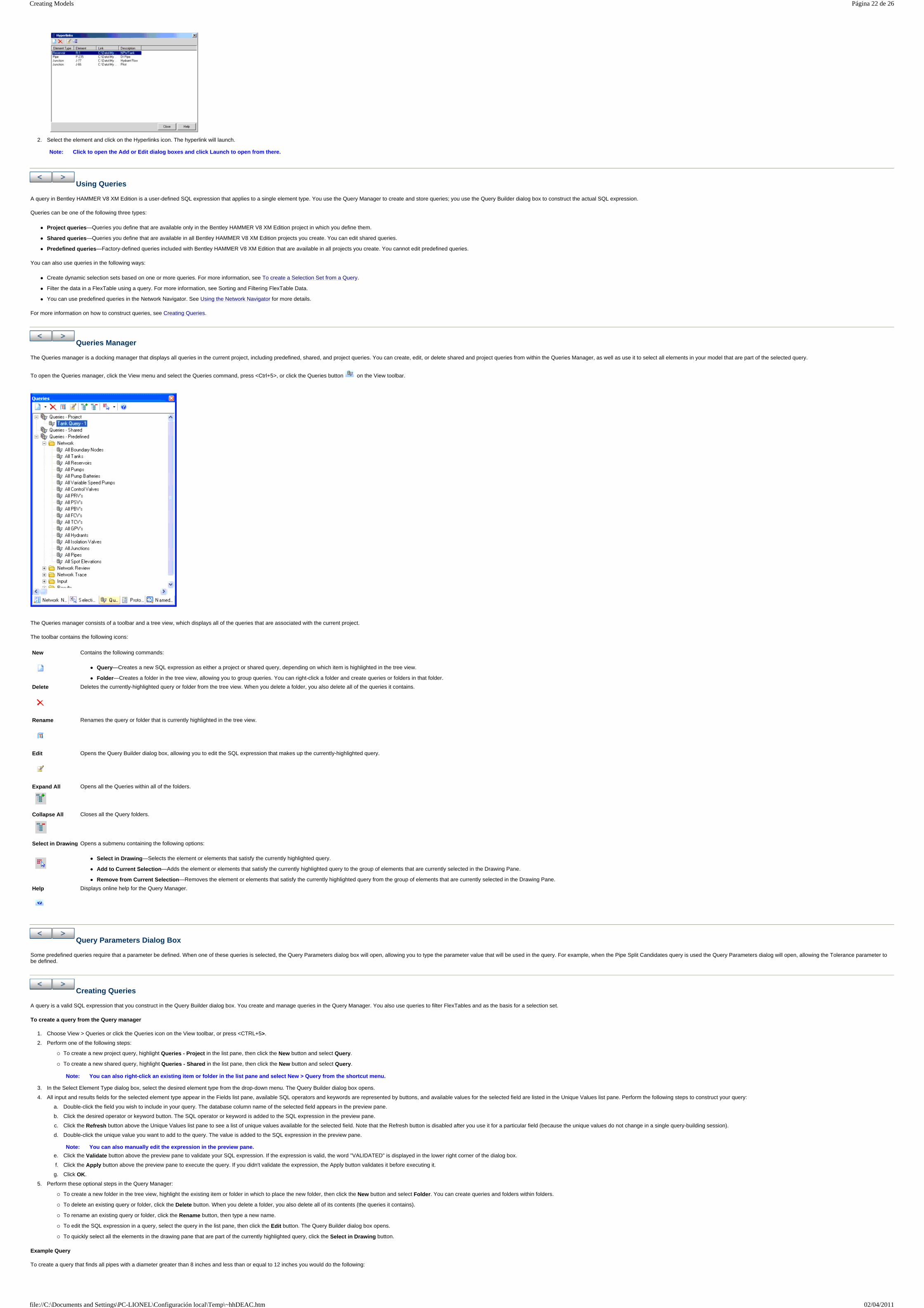
2. Select the element and click on the Hyperlinks icon. The hyperlink will launch.
Using Queries
A query in Bentley HAMMER V8 XM Edition is a user-defined SQL expression that applies to a single element type. You use the Query Manager to create and store queries; you use the Query Builder dialog box to construct the actual SQL expression.
Queries can be one of the following three types:
Project queries—Queries you define that are available only in the Bentley HAMMER V8 XM Edition project in which you define them.
Shared queries—Queries you define that are available in all Bentley HAMMER V8 XM Edition projects you create. You can edit shared queries.
Predefined queries—Factory-defined queries included with Bentley HAMMER V8 XM Edition that are available in all projects you create. You cannot edit predefined queries.
You can also use queries in the following ways:
Create dynamic selection sets based on one or more queries. For more information, see To create a Selection Set from a Query.
Filter the data in a FlexTable using a query. For more information, see Sorting and Filtering FlexTable Data.
You can use predefined queries in the Network Navigator. See Using the Network Navigator for more details.
For more information on how to construct queries, see Creating Queries.
Queries Manager
The Queries manager is a docking manager that displays all queries in the current project, including predefined, shared, and project queries. You can create, edit, or delete shared and project queries from within the Queries Manager, as well as use it to select all elements in your model that are part of the selected query.
To open the Queries manager, click the View menu and select the Queries command, press <Ctrl+5>, or click the Queries button on the View toolbar.
The Queries manager consists of a toolbar and a tree view, which displays all of the queries that are associated with the current project.
The toolbar contains the following icons:
Query Parameters Dialog Box
Some predefined queries require that a parameter be defined. When one of these queries is selected, the Query Parameters dialog box will open, allowing you to type the parameter value that will be used in the query. For example, when the Pipe Split Candidates query is used the Query Parameters dialog will open, allowing the Tolerance parameter to be defined.
Creating Queries
A query is a valid SQL expression that you construct in the Query Builder dialog box. You create and manage queries in the Query Manager. You also use queries to filter FlexTables and as the basis for a selection set.
To create a query from the Query manager
1. Choose View > Queries or click the Queries icon on the View toolbar, or press <CTRL+5>.
2. Perform one of the following steps:
To create a new project query, highlight Queries - Project in the list pane, then click the New button and select Query.
To create a new shared query, highlight Queries - Shared in the list pane, then click the New button and select Query.
3. In the Select Element Type dialog box, select the desired element type from the drop-down menu. The Query Builder dialog box opens.
4. All input and results fields for the selected element type appear in the Fields list pane, available SQL operators and keywords are represented by buttons, and available values for the selected field are listed in the Unique Values list pane. Perform the following steps to construct your query:
a. Double-click the field you wish to include in your query. The database column name of the selected field appears in the preview pane.
b. Click the desired operator or keyword button. The SQL operator or keyword is added to the SQL expression in the preview pane.
c. Click the Refresh button above the Unique Values list pane to see a list of unique values available for the selected field. Note that the Refresh button is disabled after you use it for a particular field (because the unique values do not change in a single query-building session).
d. Double-click the unique value you want to add to the query. The value is added to the SQL expression in the preview pane.
e. Click the Validate button above the preview pane to validate your SQL expression. If the expression is valid, the word "VALIDATED" is displayed in the lower right corner of the dialog box.
f. Click the Apply button above the preview pane to execute the query. If you didn't validate the expression, the Apply button validates it before executing it.
g. Click OK.
5. Perform these optional steps in the Query Manager:
To create a new folder in the tree view, highlight the existing item or folder in which to place the new folder, then click the New button and select Folder. You can create queries and folders within folders.
To delete an existing query or folder, click the Delete button. When you delete a folder, you also delete all of its contents (the queries it contains).
To rename an existing query or folder, click the Rename button, then type a new name.
To edit the SQL expression in a query, select the query in the list pane, then click the Edit button. The Query Builder dialog box opens.
To quickly select all the elements in the drawing pane that are part of the currently highlighted query, click the Select in Drawing button.
Example Query
To create a query that finds all pipes with a diameter greater than 8 inches and less than or equal to 12 inches you would do the following:
Note: Click to open the Add or Edit dialog boxes and click Launch to open from there.
New
Contains the following commands:
Query—Creates a new SQL expression as either a project or shared query, depending on which item is highlighted in the tree view.
Folder—Creates a folder in the tree view, allowing you to group queries. You can right-click a folder and create queries or folders in that folder.
Delete
Deletes the currently-highlighted query or folder from the tree view. When you delete a folder, you also delete all of the queries it contains.
Rename
Renames the query or folder that is currently highlighted in the tree view.
Edit
Opens the Query Builder dialog box, allowing you to edit the SQL expression that makes up the currently-highlighted query.
Expand All
Opens all the Queries within all of the folders.
Collapse All
Closes all the Query folders.
Select in Drawing
Opens a submenu containing the following options:
Select in Drawing—Selects the element or elements that satisfy the currently highlighted query.
Add to Current Selection—Adds the element or elements that satisfy the currently highlighted query to the group of elements that are currently selected in the Drawing Pane.
Remove from Current Selection—Removes the element or elements that satisfy the currently highlighted query from the group of elements that are currently selected in the Drawing Pane.
Help
Displays online help for the Query Manager.
Note: You can also right-click an existing item or folder in the list pane and select New > Query from the shortcut menu.
Note: You can also manually edit the expression in the preview pane.
Página 22 de 26Creating Models
02/04/2011file://C:\Documents and Settings\PC-LIONEL\Configuración local\Temp\~hhDEAC.htm
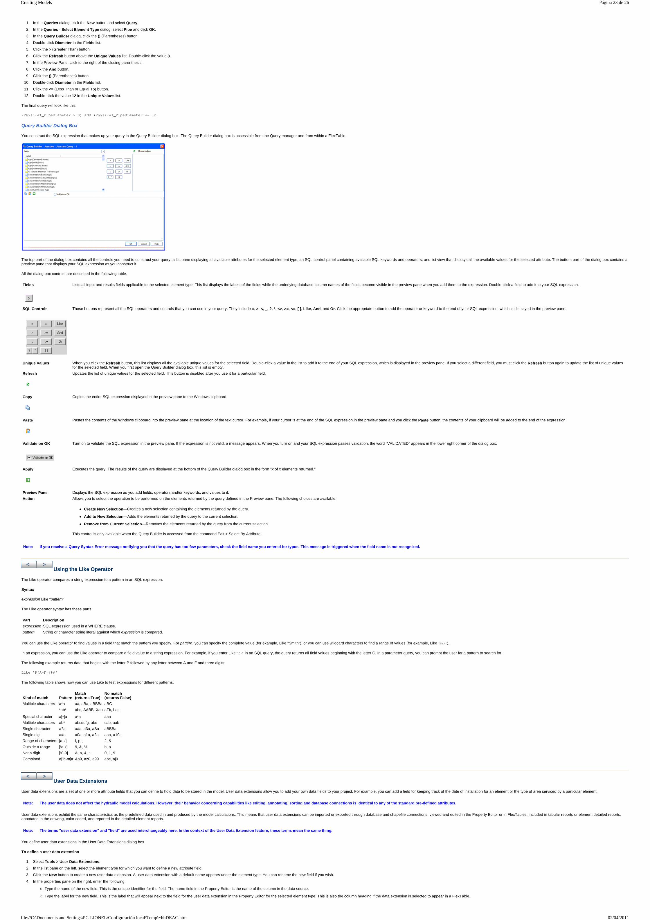
1. In the Queries dialog, click the New button and select Query.
2. In the Queries - Select Element Type dialog, select Pipe and click OK.
3. In the Query Builder dialog, click the () (Parentheses) button.
4. Double-click Diameter in the Fields list.
5. Click the > (Greater Than) button.
6. Click the Refresh button above the Unique Values list. Double-click the value 8.
7. In the Preview Pane, click to the right of the closing parenthesis.
8. Click the And button.
9. Click the () (Parentheses) button.
10. Double-click Diameter in the Fields list.
11. Click the <= (Less Than or Equal To) button.
12. Double-click the value 12 in the Unique Values list.
The final query will look like this:
(Physical_PipeDiameter > 8) AND (Physical_PipeDiameter <= 12)
Query Builder Dialog Box
You construct the SQL expression that makes up your query in the Query Builder dialog box. The Query Builder dialog box is accessible from the Query manager and from within a FlexTable.
The top part of the dialog box contains all the controls you need to construct your query: a list pane displaying all available attributes for the selected element type, an SQL control panel containing available SQL keywords and operators, and list view that displays all the available values for the selected attribute. The bottom part of the dialog box contains a preview pane that displays your SQL expression as you construct it.
All the dialog box controls are described in the following table.
Using the Like Operator
The Like operator compares a string expression to a pattern in an SQL expression.
Syntax
expression Like "pattern"
The Like operator syntax has these parts:
You can use the Like operator to find values in a field that match the pattern you specify. For pattern, you can specify the complete value (for example, Like "Smith"), or you can use wildcard characters to find a range of values (for example, Like "Sm*").
In an expression, you can use the Like operator to compare a field value to a string expression. For example, if you enter Like "C*" in an SQL query, the query returns all field values beginning with the letter C. In a parameter query, you can prompt the user for a pattern to search for.
The following example returns data that begins with the letter P followed by any letter between A and F and three digits:
Like "P[A-F]###"
The following table shows how you can use Like to test expressions for different patterns.
User Data Extensions
User data extensions are a set of one or more attribute fields that you can define to hold data to be stored in the model. User data extensions allow you to add your own data fields to your project. For example, you can add a field for keeping track of the date of installation for an element or the type of area serviced by a particular element.
User data extensions exhibit the same characteristics as the predefined data used in and produced by the model calculations. This means that user data extensions can be imported or exported through database and shapefile connections, viewed and edited in the Property Editor or in FlexTables, included in tabular reports or element detailed reports, annotated in the drawing, color coded, and reported in the detailed element reports.
You define user data extensions in the User Data Extensions dialog box.
To define a user data extension
1. Select Tools > User Data Extensions.
2. In the list pane on the left, select the element type for which you want to define a new attribute field.
3. Click the New button to create a new user data extension. A user data extension with a default name appears under the element type. You can rename the new field if you wish.
4. In the properties pane on the right, enter the following:
Type the name of the new field. This is the unique identifier for the field. The name field in the Property Editor is the name of the column in the data source.
Type the label for the new field. This is the label that will appear next to the field for the user data extension in the Property Editor for the selected element type. This is also the column heading if the data extension is selected to appear in a FlexTable.
Fields
Lists all input and results fields applicable to the selected element type. This list displays the labels of the fields while the underlying database column names of the fields become visible in the preview pane when you add them to the expression. Double-click a field to add it to your SQL expression.
SQL Controls
These buttons represent all the SQL operators and controls that you can use in your query. They include =, >, <, _, ?, *, <>, >=, <=, [ ], Like, And, and Or. Click the appropriate button to add the operator or keyword to the end of your SQL expression, which is displayed in the preview pane.
Unique Values When you click the Refresh button, this list displays all the available unique values for the selected field. Double-click a value in the list to add it to the end of your SQL expression, which is displayed in the preview pane. If you select a different field, you must click the Refresh button again to update the list of unique values for the selected field. When you first open the Query Builder dialog box, this list is empty.
Refresh
Updates the list of unique values for the selected field. This button is disabled after you use it for a particular field.
Copy
Copies the entire SQL expression displayed in the preview pane to the Windows clipboard.
Paste
Pastes the contents of the Windows clipboard into the preview pane at the location of the text cursor. For example, if your cursor is at the end of the SQL expression in the preview pane and you click the Paste button, the contents of your clipboard will be added to the end of the expression.
Validate on OK
Turn on to validate the SQL expression in the preview pane. If the expression is not valid, a message appears. When you turn on and your SQL expression passes validation, the word "VALIDATED" appears in the lower right corner of the dialog box.
Apply
Executes the query. The results of the query are displayed at the bottom of the Query Builder dialog box in the form "x of x elements returned."
Preview Pane Displays the SQL expression as you add fields, operators and/or keywords, and values to it.
Action Allows you to select the operation to be performed on the elements returned by the query defined in the Preview pane. The following choices are available:
Create New Selection—Creates a new selection containing the elements returned by the query.
Add to New Selection—Adds the elements returned by the query to the current selection.
Remove from Current Selection—Removes the elements returned by the query from the current selection.
This control is only available when the Query Builder is accessed from the command Edit > Select By Attribute.
Note: If you receive a Query Syntax Error message notifying you that the query has too few parameters, check the field name you entered for typos. This message is triggered when the field name is not recognized.
Part Description
expression SQL expression used in a WHERE clause.
pattern String or character string literal against which expression is compared.
Kind of match
Pattern
Match (returns True)
No match (returns False)
Multiple characters a*a aa, aBa, aBBBa aBC
*ab* abc, AABB, Xab aZb, bac
Special character a[*]a a*a aaa
Multiple characters ab* abcdefg, abc cab, aab
Single character a?a aaa, a3a, aBa aBBBa
Single digit a#a a0a, a1a, a2a aaa, a10a
Range of characters [a-z] f, p, j 2, &
Outside a range [!a-z] 9, &, % b, a
Not a digit [!0-9] A, a, &, ~ 0, 1, 9
Combined a[!b-m]# An9, az0, a99 abc, aj0
Note: The user data does not affect the hydraulic model calculations. However, their behavior concerning capabilities like editing, annotating, sorting and database connections is identical to any of the standard pre-defined attributes.
Note: The terms "user data extension" and "field" are used interchangeably here. In the context of the User Data Extension feature, these terms mean the same thing.
Página 23 de 26Creating Models
02/04/2011file://C:\Documents and Settings\PC-LIONEL\Configuración local\Temp\~hhDEAC.htm

Click the Ellipses (...) button in the Category field, then use the drop-down menu in the Select Category dialog box to select an existing category in which the new field will appear in the Property Editor. To create a new category, simply type the category name in the field.
Type a number in the Field Order Index field. This is the display order of fields within a particular category in the Property Editor. This order also controls the order of columns in Alternative tables. An entry of 0 means the new field will be displayed first within the specified category.
Type a description for the field. This description will appear at the bottom of the Property Editor when the field is selected for an element in your model. You can use this field as a reminder about the purpose of the field.
Select an alternative from the drop-down menu in the Alternative field. This is the alternative that you want to extend with the new field.
Select a data type from the drop-down menu in the Data Type field.
If you select Enumerated, an Ellipses (...) button appears in the Default Value field. Enumerated user data extensions are fields that present multiple choices. Enter the default value for the new field. If the data type is Enumerated, click the Ellipses (...) button to display the Enumeration Editor dialog box, where you define enumerated members.
5. Perform the following optional steps:
To import an existing User Data Extension XML File, click the Import button, then select the file you want to import. User Data Extension XML Files contain the file name extension .xml or .udx.xml.
To export existing user data extensions, click the Export to XML button, then type the name of the udx.xml file. All user data extensions for all element types defined in the current project are exported.
To share the new field among two or more element types, select the user data extension in the list pane, then click the Sharing button or right-click and select Sharing. In the Shared Field Specification dialog box, select the check box next to the element or elements that will share the user data extension. The icon next to the user data extension changes to indicate that it is a shared field. For more information, see Sharing User Data Extensions Among Element Types.
To delete an existing user data extension, select the user data extension you want to delete in the list pane, then click the Delete button, or right-click and select Delete.
To rename the display label of an existing user data extension, select the user data extension in the list pane, click the Rename button or right-click and select Rename, then type the new display label.
To expand the list of elements and view all user data extensions, click the Expand All button.
To collapse the list of elements so that no user data extensions are displayed, click the Collapse All button.
6. Click OK to close the dialog box and save your user data extensions. The new field(s) you created will appear in the Property Editor for every instance of the specified element type in your model.
User Data Extensions Dialog Box
The User Data Extensions dialog box displays a summary of the user data extensions associated with the current project. The dialog box contains a toolbar, a list pane displaying all available Bentley HAMMER element types, and a property editor.
The toolbar contains the following controls:
The property editor section of the dialog contains following fields, which define your new user data extension:
Sharing User Data Extensions Among Element Types
You can share user data extensions across multiple element types in Bentley HAMMER. Shared user data extensions are displayed in the Property Editor for all elements types that share that field.
The icons displayed next to the user data extensions in the User Data Extensions dialog box change depending on the status of the field:
Indicates a new unsaved user data extension.
Indicates a user data extension that has been saved to the data source.
Indicates a user data extension that is shared among multiple element types but has not been applied to the data source.
Indicates a user data extension that is shared among multiple element types and that has been applied to the data source. Fields with this icon appear in the Property Editor for any elements of the associated element types that appear in your model.
Observe the following rules when sharing user data extensions:
You can select any number of element types with which to share the field. The list is limited to element types that support the Alternative defined for the Field. For example, the Physical Alternative may only apply to five of the element types. In this case, you will only see these five items listed in the Alternative drop-down menu.
You cannot use the sharing feature to move a field from one element type to another. Validation is in place to ensure that only one item is selected and if it is the same as the original, default selection. If it is not, a message appears telling you that when sharing a field, you must select at least two element types, or select the original element type.
To unshare a field that is shared among multiple element types, right-click the user data extension you want to keep in the list pane, then select Sharing. Clear all the element types that you do not want to share the field and click OK. If you leave only one element type checked in the Shared Field Specification dialog box, it must be the original element type for which you created the user data extension.
The fields that were located under the tank and pipe element type root nodes will be removed completely.
You can also unshare a field by using the Delete button or right-clicking and selecting Delete. This will unshare and delete the field.
To share a user data extension
1. Open the User Data Extensions dialog box by selecting Tools > User Data Extensions.
2. In the list pane, create a new user data extension to share or select an existing user data extension you want to share, then click the Sharing button.
3. In the Shared Field Specification dialog box, select the check box next to each element type that will share the user data extension.
4. Click OK.
5. The icon next to the user data extension in the list pane changes to indicate that it is a shared field.
Shared Field Specification Dialog Box
Select element types to share a user data extension in the Shared Field Specification dialog box. The dialog box contains a list of all possible element types with check boxes.
Import Merges the user data extensions in a saved User Data Extension XML file (.udx.xml or .xml) into the current project. Importing a User Data Extension XML file will not remove any of the other data extensions defined in your project. User data extensions that have the same name as those already defined in your project will not be imported.
Export to XML
Saves existing user data extensions for all element types in your model to a User Data Extension XML file (.udx.xml) for use in a different project.
Add Field Creates a new user data extension for the currently highlighted element type.
Share Shares the current user data extension with another element type. When you click this button, the Shared Field Specification dialog box opens. For more information, see Sharing User Data Extensions Among Element Types.
Delete Field Deletes the currently highlighted user data extension
Rename Field Renames the display label of the currently highlighted user data extension.
Expand All Expands all of the branches in the hierarchy displayed in the list pane.
Collapse All Collapses all of the branches in the hierarchy displayed in the list pane.
Attribute Description
General Name The unique identifier for the field. The name field in the Property Editor is the name of the column in the data source.
Label The label that will appear next to the field for the user data extension in the Property Editor for the selected element type. This is also the column heading if the data extension is selected to appear in a FlexTable.
Category The section in the Property Editor for the selected element type in which the new field will appear. You can create a new category or use an existing category. For example, you can create a new field for junctions and display it in the Physical section of that element's Property Editor.
Field Order Index
The display order of fields within a particular category in the Property Editor. This order also controls the order of columns in Alternative tables. An entry of 0 means the new field will be displayed first within the specified category.
Field Description The description of the field. This description will appear at the bottom of the Property Editor when the field is selected for an element in your model. You can use this field as a reminder about the purpose of the field.
Alternative Selects an existing alternative to extend with the new field.
Referenced By Displays all the element types that are using the field. For example, if you create a field called "Installation Date" and you set it up to be shared, this field will show the element types that share this field. So for example, if you set up a field to be shared by junctions and catch basins, the Referenced By field would show "Manhole, Catch Basin".
Units Data Type Specifies the data type for the user data extension. Click the down arrow in the field then select one of the following data types from the drop-down menu:
Integer—Any positive or negative whole number.
Real—Any fractional decimal number (for example, 3.14). It can also be unitized with the provided options.
Text—Any string (text) value up to 255 characters long.
Long Text—Any string (text) up to 65,526 characters long.
Date/Time—The current date. The current date appears by default in the format month/day/year. Click the down arrow to change the default date.
Boolean—True or False.
Enumerated—When you select this data type, an Ellipses button appears in the Default Value field. Click the Ellipses (...) button to display the Enumeration Editor dialog box, where you can add enumerated members and their associated values. For more information, see Enumeration Editor Dialog Box.
Default Value The default value for the user data extension. The default value must be consistent with the selected data type. If you chose Enumerated as the data type, click the Ellipses (...) button to display the Enumeration Editor.
Dimension Specifies the unit type. Click the drop-down arrow in the field to see a list of all available dimensions. This field is available only when you select Real as the Data Type.
Storage Unit Specifies the storage units for the field. Click the drop-down arrow in the field to see a list of all available units; the units listed change depending on the Dimension you select. This field is available only when you select Real as the Data Type.
Numeric Formatter
Selects a number format for the field. Click the drop-down arrow in the field to see a list of all available number formats; the number formats listed change depending on the Dimension you select. For example, if you select Flow as the Dimension, you can select Flow, Flow - Pressurized Condition, Flow Tolerance, or Unit Load as the Numeric Formatter. This field is available only when you select Real as the Data Type.
Página 24 de 26Creating Models
02/04/2011file://C:\Documents and Settings\PC-LIONEL\Configuración local\Temp\~hhDEAC.htm
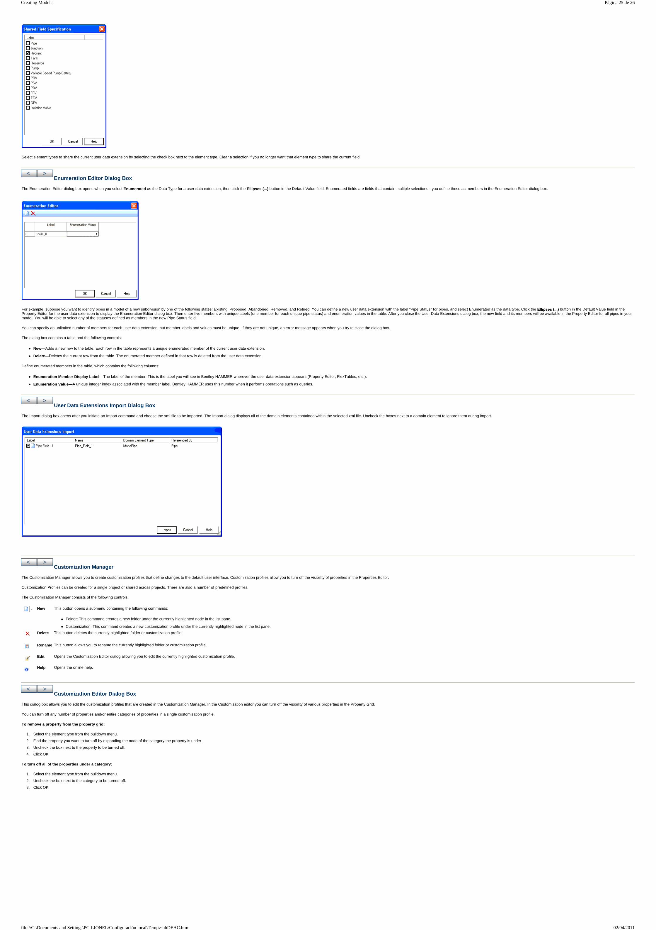
Select element types to share the current user data extension by selecting the check box next to the element type. Clear a selection if you no longer want that element type to share the current field.
Enumeration Editor Dialog Box
The Enumeration Editor dialog box opens when you select Enumerated as the Data Type for a user data extension, then click the Ellipses (...) button in the Default Value field. Enumerated fields are fields that contain multiple selections - you define these as members in the Enumeration Editor dialog box.
For example, suppose you want to identify pipes in a model of a new subdivision by one of the following states: Existing, Proposed, Abandoned, Removed, and Retired. You can define a new user data extension with the label "Pipe Status" for pipes, and select Enumerated as the data type. Click the Ellipses (...) button in the Default Value field in the Property Editor for the user data extension to display the Enumeration Editor dialog box. Then enter five members with unique labels (one member for each unique pipe status) and enumeration values in the table. After you close the User Data Extensions dialog box, the new field and its members will be available in the Property Editor for all pipes in your model. You will be able to select any of the statuses defined as members in the new Pipe Status field.
You can specify an unlimited number of members for each user data extension, but member labels and values must be unique. If they are not unique, an error message appears when you try to close the dialog box.
The dialog box contains a table and the following controls:
New—Adds a new row to the table. Each row in the table represents a unique enumerated member of the current user data extension.
Delete—Deletes the current row from the table. The enumerated member defined in that row is deleted from the user data extension.
Define enumerated members in the table, which contains the following columns:
Enumeration Member Display Label—The label of the member. This is the label you will see in Bentley HAMMER wherever the user data extension appears (Property Editor, FlexTables, etc.).
Enumeration Value—A unique integer index associated with the member label. Bentley HAMMER uses this number when it performs operations such as queries.
User Data Extensions Import Dialog Box
The Import dialog box opens after you initiate an Import command and choose the xml file to be imported. The Import dialog displays all of the domain elements contained within the selected xml file. Uncheck the boxes next to a domain element to ignore them during import.
Customization Manager
The Customization Manager allows you to create customization profiles that define changes to the default user interface. Customization profiles allow you to turn off the visibility of properties in the Properties Editor.
Customization Profiles can be created for a single project or shared across projects. There are also a number of predefined profiles.
The Customization Manager consists of the following controls:
Customization Editor Dialog Box
This dialog box allows you to edit the customization profiles that are created in the Customization Manager. In the Customization editor you can turn off the visibility of various properties in the Property Grid.
You can turn off any number of properties and/or entire categories of properties in a single customization profile.
To remove a property from the property grid:
1. Select the element type from the pulldown menu.
2. Find the property you want to turn off by expanding the node of the category the property is under.
3. Uncheck the box next to the property to be turned off.
4. Click OK.
To turn off all of the properties under a category:
1. Select the element type from the pulldown menu.
2. Uncheck the box next to the category to be turned off.
3. Click OK.
New This button opens a submenu containing the following commands:
Folder: This command creates a new folder under the currently highlighted node in the list pane.
Customization: This command creates a new customization profile under the currently highlighted node in the list pane.
Delete This button deletes the currently highlighted folder or customization profile.
Rename This button allows you to rename the currently highlighted folder or customization profile.
Edit Opens the Customization Editor dialog allowing you to edit the currently highlighted customization profile.
Help Opens the online help.
Página 25 de 26Creating Models
02/04/2011file://C:\Documents and Settings\PC-LIONEL\Configuración local\Temp\~hhDEAC.htm
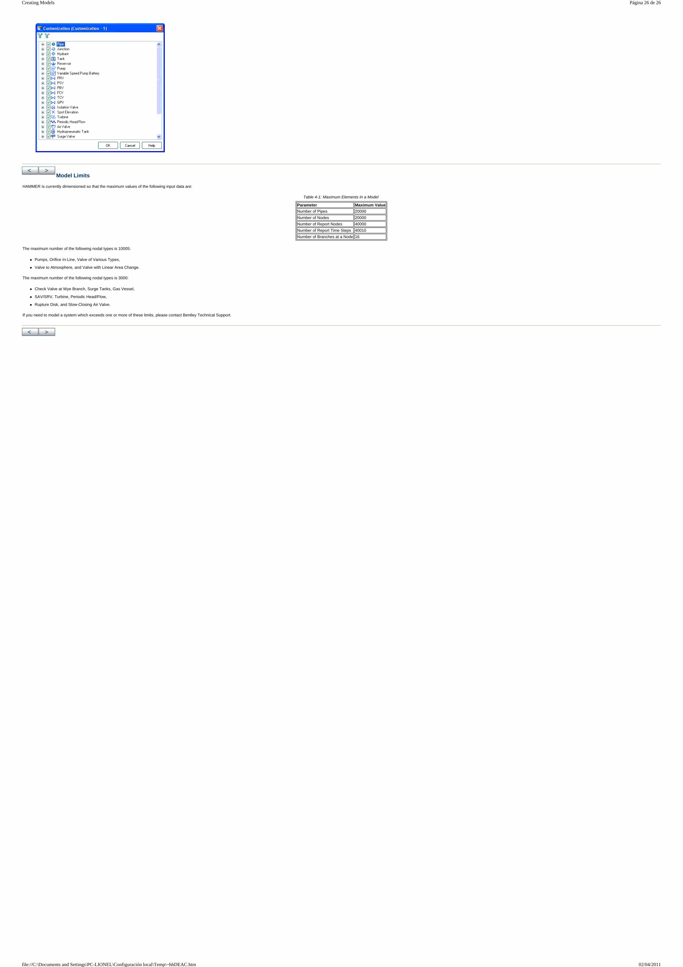
Model Limits
HAMMER is currently dimensioned so that the maximum values of the following input data are:
The maximum number of the following nodal types is 10005:
Pumps, Orifice In-Line, Valve of Various Types,
Valve to Atmosphere, and Valve with Linear Area Change.
The maximum number of the following nodal types is 3000:
Check Valve at Wye Branch, Surge Tanks, Gas Vessel,
SAV/SRV, Turbine, Periodic Head/Flow,
Rupture Disk, and Slow-Closing Air Valve.
If you need to model a system which exceeds one or more of these limits, please contact Bentley Technical Support.
Table 4-1: Maximum Elements In a Model
Parameter Maximum Value
Number of Pipes 20000
Number of Nodes 20000
Number of Report Nodes 40000
Number of Report Time Steps 40010
Number of Branches at a Node 16
Página 26 de 26Creating Models
02/04/2011file://C:\Documents and Settings\PC-LIONEL\Configuración local\Temp\~hhDEAC.htm