04b-tutorial ct selection
DESCRIPTION
ct selectionTRANSCRIPT

Tutorial
Current Transformer Requirements for Protection

1. A 400/5A bar primary CT with a Stalloy core supplies a 3VA CDG11 set at 10% of nominal current. It is required to cater for a current of 10 times relay setting, neglecting the CT resistance and any non linearity in the relay impedance. Consider a conductor diameter of 2 cm’s and allow 2 cm’s on each side of the core for the secondary winding and the insulation. System frequency is 50Hz. Find (i) The minimum knee point voltage. (ii) The cross sectional area of the core.
(iii) A possible set of CT dimensions, ensuring that the CT will fit in the available housing space of 20 cm’s diameter and 15 cm’s deep. (iv) The Kv factor in volts/tesla (v) The Ki factor in mm/turn
Note* Take Bm – Max flux density of stalloy = 1Wb/m2
CT Ratio = 400/5A ∴ N = 80 Turns RCT is ignored in this example.
Ip/N Xct
CDG11
3VA
Rct
5 Amp RelaySet at 10%

2. Three CROSS (Cold Rolled Grain Orientated Silicon Steel) 400/5A Bar Primary current transformers have the following characteristics:
Secondary resistance = 0.2 Ω Kv = 20V/tesla Ki = 4mm/turn The CT’s are connected to give phase and E/F protection using a CDG31 50-200% overcurrent relay set to 125%, and a CDG11 20-80% earth fault relay set at 40%. What is: a.) The minimum primary current for operation of the phase fault
relays for a 3 phase fault b.) The minimum primary current for operation of the earth fault
relay for a single phase to ground fault.
Assume relay burden at setting is 3VA for the phase fault relays and 2.4VA at setting for earth fault relays. Use the magnetising curves provided to estimate the magnetising currents of both the active and idle CT’s.

3. An earthed 132kV transformer is protected by Restricted Earth Fault protection using 4 CT’s and an MCAG14 relay plus stabilising resistor. Relay setting range 0.1-0.4A, set at 0.4A.
The system fault level is 3500MVA, and the loop impedance from relay to the CT’s = 2.0 Ω The CT details are as follows: Ratio = 500/1 Material = CROSS Kv = 272 V/tesla Ki = 2.08 mm/turn R = 0.7 Ω Find the primary fault setting and the minimum stabilising resistor value. Assume relay burden is 1VA. Use magnetising curve supplied, scale the Kv and Ki factors to calculate the magnetising current.
Rs500/1
500/1
MCAG14

Solutions: 1. I. Setting of relay = 10% of 5A = 0.5 Amps
CDG11 consumes constant VA at setting, therefore 3VA at 0.5 A must demand 6 V at the relay terminals (VA = V x I). If the CT is to be capable of driving 10 x setting current through the re;ay, then the CT must have a minimum knee point voltage of 10 x 6 V. ∴ Minimum Vk = 60 V.
II. Calculate the cross sectional area of the core using the formula
ES = 4.44 f Bm A N (all metric units) All factors but A are known so,
60 = 4.44 x 50 x 1 x A x 80 ∴A = 2003378.0
8022260 m=×
= 33.78 cm2 (area of Stalloy Core)
III. Calculation of a possible set of CT dimensions
With 2 cm’s diameter primary conductor and 4 cm’s for winding and insulation, minimum internal diameter = 6 cm’s. Assume core to be approximately square e.g. 33.8 cm2 = 5 cm x 6.76 cm

Proposed size for core.
Mean magnetic diameter = cm11
2166
=+
Overall dimensions, including windings and insulation (2 cm)
This CT will fit within the available space of 20cm x 15cm.
16 cm
6.76 cm
6 cm
10.76 cm
2 cm 20 cm
IV. Calculation of Kv Factor
Employing metric units with core area in cm2
6045
8078.335.4
105044.4
14 =
×==×
×= − ANANKV
∴ Kv = 60 V/ tesla

V. Calculation of Ki factor
Employing metric units with mean magneetic length in mm Mean magnetic length = πD = π x 11 x 10 = 346 mm Ki = Mean magnetic length/ N = Turnmm /32.4
80346
=

2.
Relay Impedances: Phase Overcurrent = 3 VA at 125% of 5 A ∴ Z = 3/6.252 = 0.077 Ω E/F = 2.4 VA at 40% of 5 A ∴ Z = 2.4/22 = 0.6 Ω Full equivalent circuit, including magnetising impedances
O/C Earth Fault
400/5
0.077 Ohms 0.2 Ohms
0.077 Ohms 0.2 Ohms
0.077 OhmsO/C
0.2 OhmsRct
E/F0.6 Ohms
Z mag

a.) Calculate 3 phase fault primary setting
The phase currents are balanced for this condition and no current will flow in the neutral.
Setting current of overcurrent relays = 6.25 A ∴ Voltage which needs to be developed within the CT = 6.25 x total impedance. Assume all impedances have the same angle for simplicity ∴ V at CT = 6.25(0.077 + 0.2) = 1.73 V
To calculate expected magnetising current in CT: I. Scale magnetising curve with the Kv and Ki factors given
in the question ( as traced)
In = 0
6.25 A0.077 0.2 1.73 V
4 V
1.73 V
8 V
0.08 A

II. Scale of 1.73 V – Result = 0.02 A Neglecting any phase angle differences Isec’y = 6.25 A + Imag = 6.27 Amps ∴ Primary setting for O/C relays = 6.27 x 80 = 501.6 A for 3 phase faults
b.) Calculate earth fault primary setting
Step A Calculate voltage across E/F relay = Setting Current x E/F relay impedance = 2.0 x 0.6 Ω = 1.2 V
Step B Calculate the magnetising current in the 2 idle
sound phase CT’s, noting they have 1.2 V impressed across them
Use magnetising curve – scaled by Kv and Ki –as before
0.16 A
4 V
1.2 V
8 V
0.08 A
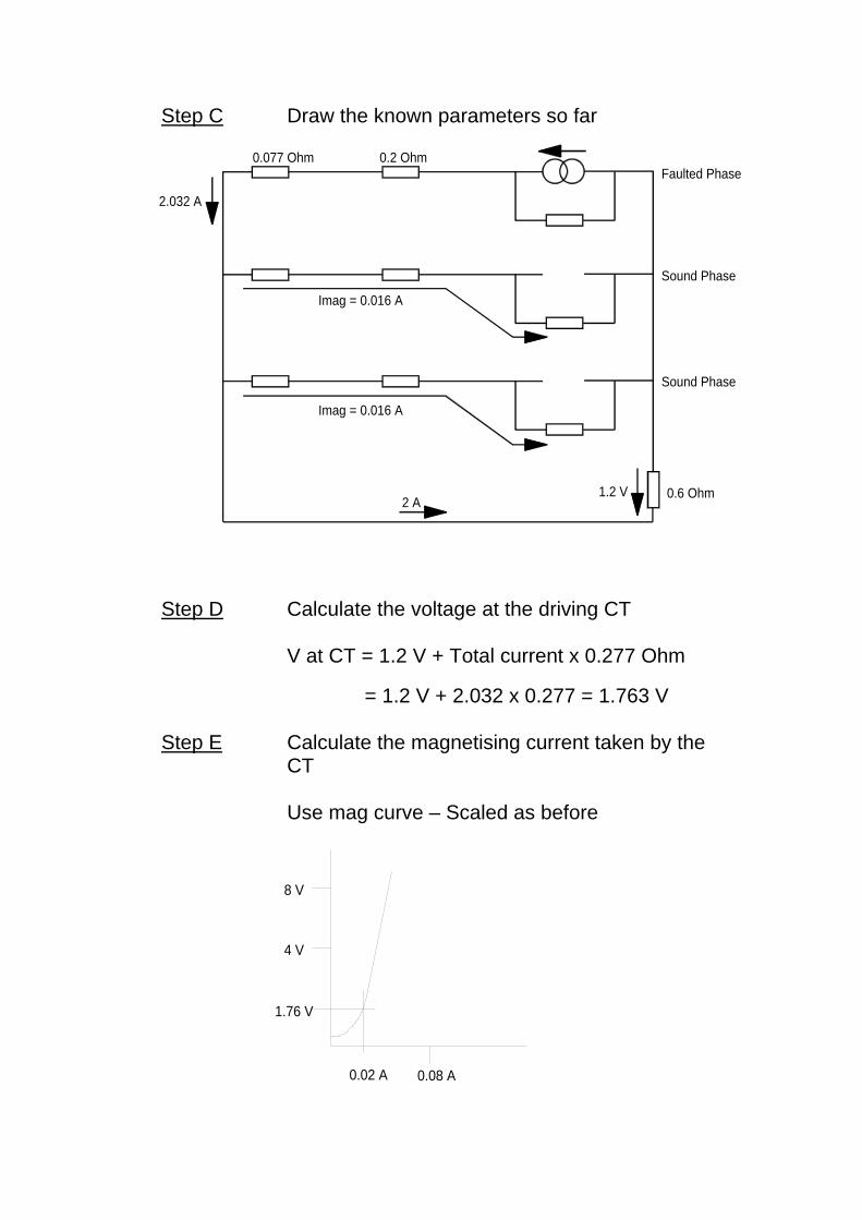
Step C Draw the known parameters so far
Step D Calculate the voltage at the driving CT
0.6 Ohm2 A
1.2 V
Imag = 0.016 A
Imag = 0.016 A
0.077 Ohm
2.032 A
0.2 Ohm
Sound Phase
Sound Phase
Faulted Phase
V at CT = 1.2 V + Total current x 0.277 Ohm
= 1.2 V + 2.032 x 0.277 = 1.763 V
Step E Calculate the magnetising current taken by the CT
Use mag curve – Scaled as before
0.02 A
4 V
1.76 V
8 V
0.08 A

Step F Construct the final diagram, assuming all currents are in phase.
0.6 Ohm2 A1.2 V
Imag = 0.016 A
Imag = 0.016 A
0.077 Ohm
2.032 A
0.2 Ohm
Sound Phase
Sound Phase
2.052 A
0.02 A
Faulted Phase
Current in driving CT = 2.052 A sec’y = 164.15 A primary ∴ Primary E/F sensitivity = 164.2A
3.
Step A Calculate E/F rating MVA rating/phase = 3500/3 Phase/neutral voltage = 132/ √3
∴ Fault level = kA3.152.7667.1166
3132
33500
==
Step B Calculate CT secondary current (prospective) AA
nII P
S 6.30500
15300==

Step C Draw detailed diagram, as seen from the CT on
the neutral
Rloop
2.0
Fault Is = 30.6 AIf other CT's Saturate
Rct
0.7Rstab
Step D Calculate recommended voltage setting of high
impedance relay, ie, MCAG14 + RSTAB V setting = If (sec’y) x resistance in one leg of
supply. = 30.6 A x (0.7 + 2.0) = 82.6 V Step E Calculate the mag current taken by the CT –
using curve supplied and scaled by the Kv and Ki factors given
0.025 A
82.6 V
54.4 V
108.8 V
0.0416 A
Step F Calculate total current in driving CT (assuming currents are in phase) at setting.
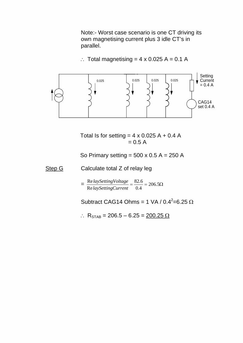
Note:- Worst case scenario is one CT driving its own magnetising current plus 3 idle CT’s in parallel.
∴ Total magnetising = 4 x 0.025 A = 0.1 A
0.0250.025
CAG14set 0.4 A
0.025 0.025SettingCurrent= 0.4 A
Total Is for setting = 4 x 0.025 A + 0.4 A = 0.5 A So Primary setting = 500 x 0.5 A = 250 A
Step G Calculate total Z of relay leg = Ω== 5.206
4.06.82
ReRe
CurrentlaySettingVoltagelaySetting
Subtract CAG14 Ohms = 1 VA / 0.42=6.25 Ω ∴ RSTAB = 206.5 – 6.25 = 200.25 Ω