0458 640 001 gb - esab welding & · pdf file · 2012-12-140458 640 001 gb...
TRANSCRIPT
GB
Valid for serial no. 050--xxx--xxxx, 105--xxx--xxxx,347--xxx--xxxx, 445--xxx--xxxx, 524--xxx--xxxx
0458 640 001 GB 050517
AristoTig 400
Instruction manual
-- 2 --TOCe
Rights reserved to alter specifications without notice.
1 DIRECTIVE 3. . . . . . . . . . . . . . . . . . . . . . . . . . . . . . . . . . . . . . . . . . . . . . . . . . . . . . . .2 SAFETY 3. . . . . . . . . . . . . . . . . . . . . . . . . . . . . . . . . . . . . . . . . . . . . . . . . . . . . . . . . . .3 INTRODUCTION 5. . . . . . . . . . . . . . . . . . . . . . . . . . . . . . . . . . . . . . . . . . . . . . . . . . .
3.1 Equipment 5. . . . . . . . . . . . . . . . . . . . . . . . . . . . . . . . . . . . . . . . . . . . . . . . . . . . . . . . . . . . . . . .3.2 The control panel 5. . . . . . . . . . . . . . . . . . . . . . . . . . . . . . . . . . . . . . . . . . . . . . . . . . . . . . . . . .
4 TECHNICAL DATA 6. . . . . . . . . . . . . . . . . . . . . . . . . . . . . . . . . . . . . . . . . . . . . . . . .5 INSTALLATION 7. . . . . . . . . . . . . . . . . . . . . . . . . . . . . . . . . . . . . . . . . . . . . . . . . . . .
5.1 Lifting instructions 7. . . . . . . . . . . . . . . . . . . . . . . . . . . . . . . . . . . . . . . . . . . . . . . . . . . . . . . . .5.2 Placing 7. . . . . . . . . . . . . . . . . . . . . . . . . . . . . . . . . . . . . . . . . . . . . . . . . . . . . . . . . . . . . . . . . . .5.3 Electrical installation (with autotransformer) 8. . . . . . . . . . . . . . . . . . . . . . . . . . . . . . . . . . .5.4 Mains power supply 9. . . . . . . . . . . . . . . . . . . . . . . . . . . . . . . . . . . . . . . . . . . . . . . . . . . . . . . .
6 OPERATION 10. . . . . . . . . . . . . . . . . . . . . . . . . . . . . . . . . . . . . . . . . . . . . . . . . . . . . . .6.1 Connections and control devices 10. . . . . . . . . . . . . . . . . . . . . . . . . . . . . . . . . . . . . . . . . . . .6.2 Turning on the power source 10. . . . . . . . . . . . . . . . . . . . . . . . . . . . . . . . . . . . . . . . . . . . . . . .6.3 Fan control 11. . . . . . . . . . . . . . . . . . . . . . . . . . . . . . . . . . . . . . . . . . . . . . . . . . . . . . . . . . . . . . .6.4 Overheating protection 11. . . . . . . . . . . . . . . . . . . . . . . . . . . . . . . . . . . . . . . . . . . . . . . . . . . . .6.5 Cooling unit 11. . . . . . . . . . . . . . . . . . . . . . . . . . . . . . . . . . . . . . . . . . . . . . . . . . . . . . . . . . . . . . .6.6 Remote control unit 11. . . . . . . . . . . . . . . . . . . . . . . . . . . . . . . . . . . . . . . . . . . . . . . . . . . . . . . .
7 MAINTENANCE 12. . . . . . . . . . . . . . . . . . . . . . . . . . . . . . . . . . . . . . . . . . . . . . . . . . . .7.1 Cleaning the air filter 12. . . . . . . . . . . . . . . . . . . . . . . . . . . . . . . . . . . . . . . . . . . . . . . . . . . . . . .7.2 Topping up the coolant 12. . . . . . . . . . . . . . . . . . . . . . . . . . . . . . . . . . . . . . . . . . . . . . . . . . . . .
8 FAULT TRACING 13. . . . . . . . . . . . . . . . . . . . . . . . . . . . . . . . . . . . . . . . . . . . . . . . . . .9 ORDERING OF SPARE PARTS 13. . . . . . . . . . . . . . . . . . . . . . . . . . . . . . . . . . . . . .DIAGRAM 14. . . . . . . . . . . . . . . . . . . . . . . . . . . . . . . . . . . . . . . . . . . . . . . . . . . . . . . . . . . .ORDERING NUMBER 17. . . . . . . . . . . . . . . . . . . . . . . . . . . . . . . . . . . . . . . . . . . . . . . . .SPARE PARTS LIST 18. . . . . . . . . . . . . . . . . . . . . . . . . . . . . . . . . . . . . . . . . . . . . . . . . . .ACCESSORIES 19. . . . . . . . . . . . . . . . . . . . . . . . . . . . . . . . . . . . . . . . . . . . . . . . . . . . . . .
-- 3 --bt23d0ea
1 DIRECTIVE
DECLARATION OF CONFORMITYESAB Welding Equipment AB, S--695 81 Laxå, Sweden, gives its unreserved guarantee that weldingpower source AristoTig 400 from serial number 105 complies with standard IEC/EN 60974--1, in ac-cordance with the requirements of directive (73/23/EEC) and addendum (93/68/EEC) and with stan-dard EN 50199 in accordance with the requirements of directive (89/336/EEC) and addendum(93/68/EEC).--------------------------------------------------------------------------------------------------------------------------------------
Joakim CahlinVice PresidentESAB Welding Equipment AB695 81 LAXÅSWEDEN Tel: + 46 584 81000 Fax: + 46 584 411924
Laxå 2001--04--18
2 SAFETYUsers of ESAB welding equipment have the ultimate responsibility for ensuring that anyone whoworks on or near the equipment observes all the relevant safety precautions. Safety precautionsmust meet the requirements that apply to this type of welding equipment. The following recommen-dations should be observed in addition to the standard regulations that apply to the workplace.
All work must be carried out by trained personnel well--acquainted with the operation of the weldingequipment. Incorrect operation of the equipment may lead to hazardous situations which can resultin injury to the operator and damage to the equipment.
1. Anyone who uses the welding equipment must be familiar with:S its operationS location of emergency stopsS its functionS relevant safety precautionsS welding
2. The operator must ensure that:S no unauthorized person is stationed within the working area of the equipment when it is
started up.S no--one is unprotected when the arc is struck
3. The workplace must:S be suitable for the purposeS be free from drafts
4. Personal safety equipmentS Always wear recommended personal safety equipment, such as safety glasses, flame--proof
clothing, safety gloves.S Do not wear loose--fitting items, such as scarves, bracelets, rings, etc., which could become
trapped or cause burns.
5. General precautionsS Make sure the return cable is connected securely.S Work on high voltage equipment may only be carried out by a qualified electrician.S Appropriate fire extinquishing equipment must be clearly marked and close at hand.S Lubrication and maintenance must not be carried out on the equipment during operation.
GB
-- 4 --bt23d1ea
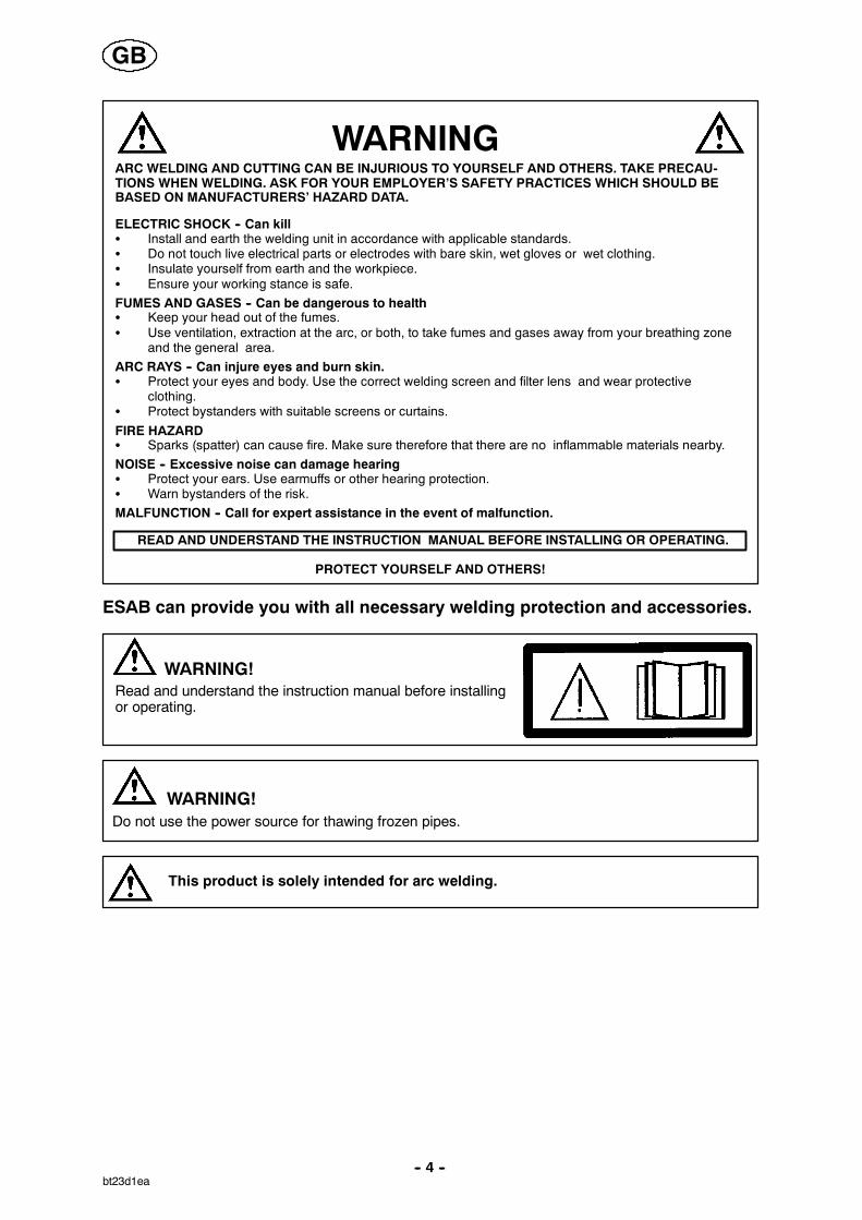
WARNING
READ AND UNDERSTAND THE INSTRUCTION MANUAL BEFORE INSTALLING OR OPERATING.
ARC WELDING AND CUTTING CAN BE INJURIOUS TO YOURSELF AND OTHERS. TAKE PRECAU-TIONS WHEN WELDING. ASK FOR YOUR EMPLOYER’S SAFETY PRACTICES WHICH SHOULD BEBASED ON MANUFACTURERS’ HAZARD DATA.
ELECTRIC SHOCK -- Can killS Install and earth the welding unit in accordance with applicable standards.S Do not touch live electrical parts or electrodes with bare skin, wet gloves or wet clothing.S Insulate yourself from earth and the workpiece.S Ensure your working stance is safe.FUMES AND GASES -- Can be dangerous to healthS Keep your head out of the fumes.S Use ventilation, extraction at the arc, or both, to take fumes and gases away from your breathing zone
and the general area.ARC RAYS -- Can injure eyes and burn skin.S Protect your eyes and body. Use the correct welding screen and filter lens and wear protective
clothing.S Protect bystanders with suitable screens or curtains.
FIRE HAZARDS Sparks (spatter) can cause fire. Make sure therefore that there are no inflammable materials nearby.NOISE -- Excessive noise can damage hearingS Protect your ears. Use earmuffs or other hearing protection.S Warn bystanders of the risk.MALFUNCTION -- Call for expert assistance in the event of malfunction.
PROTECT YOURSELF AND OTHERS!
ESAB can provide you with all necessary welding protection and accessories.
WARNING!Read and understand the instruction manual before installingor operating.
Do not use the power source for thawing frozen pipes.WARNING!
This product is solely intended for arc welding.
GB

-- 5 --bt23d1ea
3 INTRODUCTION
The AristoTig 400 is a TIG welding power source, which can also be used for MMAwelding.
There are eight variants of the power source:
S AristoTig 400 with T4 control panel
S AristoTig 400 with T6 control panel
S AristoTig 400 with cooling unit and T4 control panel
S AristoTig 400 with cooling unit and T6 control panel
S AristoTig 400 with autotransformer and T4 control panel
S AristoTig 400 with autotransformer and T6 control panel
S AristoTig 400 with cooling unit, autotransformer and T4 control panel
S AristoTig 400 with cooling unit, autotransformer and T6 control panelNB: These instructions describe an AristoTig 400 with cooling unit andautotransformer.
ESAB’s accessories for the product can be found on page 19.
3.1 Equipment
The AristoTig 400 is delivered with 5m return cable, instructions for power sourceand one instruction for the control panel.
3.2 The control panel
The power source is supplied with one of the following control panels:
S T4 panel
With a knob for adjusting the current. Other parameters are controlled bypushbuttons, with symbols in the display panel.
S T6 panel
With a knob for adjusting the current. Other parameters are controlled bypushbuttons, with text in the display panel.
See the separate instructions for detailed descriptions of the control panels.
GB
-- 6 --bt23d1ea
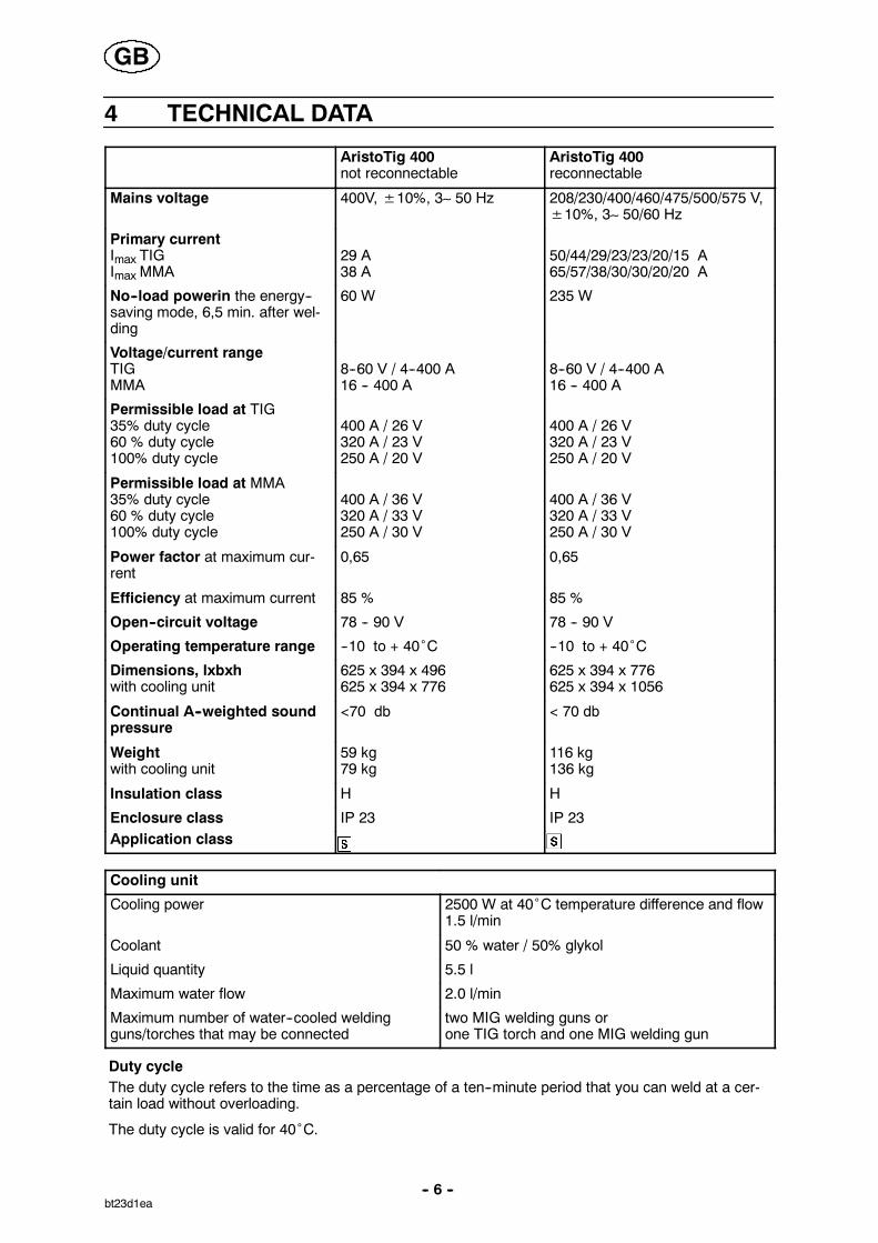
4 TECHNICAL DATA
AristoTig 400not reconnectable
AristoTig 400reconnectable
Mains voltage 400V,±10%, 3∼ 50 Hz 208/230/400/460/475/500/575 V,±10%, 3∼ 50/60 Hz
Primary currentImax TIGImax MMA
29 A38 A
50/44/29/23/23/20/15 A65/57/38/30/30/20/20 A
No--load powerin the energy--saving mode, 6,5 min. after wel-ding
60 W 235 W
Voltage/current rangeTIGMMA
8--60 V / 4--400 A16 -- 400 A
8--60 V / 4--400 A16 -- 400 A
Permissible load at TIG35% duty cycle60 % duty cycle100% duty cycle
400 A / 26 V320 A / 23 V250 A / 20 V
400 A / 26 V320 A / 23 V250 A / 20 V
Permissible load at MMA35% duty cycle60 % duty cycle100% duty cycle
400 A / 36 V320 A / 33 V250 A / 30 V
400 A / 36 V320 A / 33 V250 A / 30 V
Power factor at maximum cur-rent
0,65 0,65
Efficiency at maximum current 85 % 85 %
Open--circuit voltage 78 -- 90 V 78 -- 90 V
Operating temperature range --10 to + 40˚C --10 to + 40˚C
Dimensions, lxbxhwith cooling unit
625 x 394 x 496625 x 394 x 776
625 x 394 x 776625 x 394 x 1056
Continual A--weighted soundpressure
<70 db < 70 db
Weightwith cooling unit
59 kg79 kg
116 kg136 kg
Insulation class H H
Enclosure class IP 23 IP 23Application class
Cooling unit
Cooling power 2500 W at 40˚C temperature difference and flow1.5 l/min
Coolant 50 % water / 50% glykol
Liquid quantity 5.5 l
Maximum water flow 2.0 l/min
Maximum number of water--cooled weldingguns/torches that may be connected
two MIG welding guns orone TIG torch and one MIG welding gun
Duty cycleThe duty cycle refers to the time as a percentage of a ten--minute period that you can weld at a cer-tain load without overloading.
The duty cycle is valid for 40˚C.
GB

-- 7 --bt23d1ea
Enclosure classThe IP code indicates the enclosure class, i. e. the degree of protection against penetration by solidobjects or water. Equipment marked IP23 is designed for indoor and outdoor use.
Application class
The symbol indicates that the power source is designed for use in areas with increasedelectrical hazard.
5 INSTALLATION
The installation must be executed by a professional.
WARNING!This product is intended for industrial use. In a domestic environment this product may cause radiointerference. It is the user’s responsibility to take adequate precautions.
5.1 Lifting instructions
With power source With trolley and power source With trolley2 and power source
5.2 Placing
Position the welding power source such that its cooling air inlets and outlets are notobstructed.
GB
-- 8 --bt23d1ea
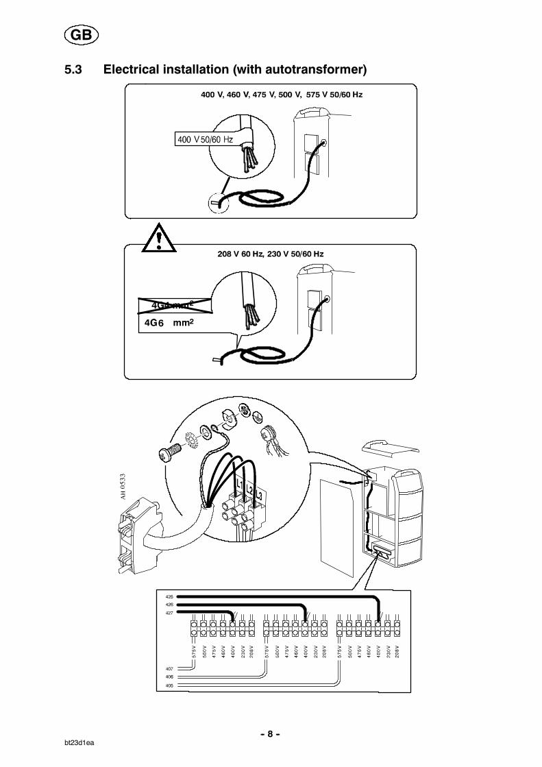
5.3 Electrical installation (with autotransformer)
GB

-- 9 --bt23d1ea
5.4 Mains power supply
Check that the unit is connected to the correct mains powersupply voltage, and that it is protected by the correct fuse sizes.A protective earth connection must be made, in accordancewith regulations.
Rating plate with supply connection data.
Recommended fuse sizes and minimum cable areasAristoTig 400 60 Hz 50/60 Hz 50 Hz 60 Hz 60 Hz 50 Hz 60 Hz
Mains voltage 208 V 230 V 400 V 460 V 475 V 500 V 575 VMains cable area,mm2
4G6 4G6 4G4 4G4 4G4 4G4 4G4
Phase current, I ef-fective
38 A 33 A 22 A 18 A 18 A 16 A 11 A
FuseAnti--surgeType C MCB
50 A50 A
50 A50 A
25 A32 A
20 A--
20 A--
16 A--
16 A--
NB: The mains cable areas and fuse sizes as shown above are in accordance with Swedishregulations. They may not be applicable in other countries: make sure that the cable area and fusesizes comply with the relevant national regulations.
GB
-- 10 --bt23d1ea
6 OPERATIONGeneral safety regulations for the handling of the equipment can be found onpage 3. Read through before you start using the equipment!
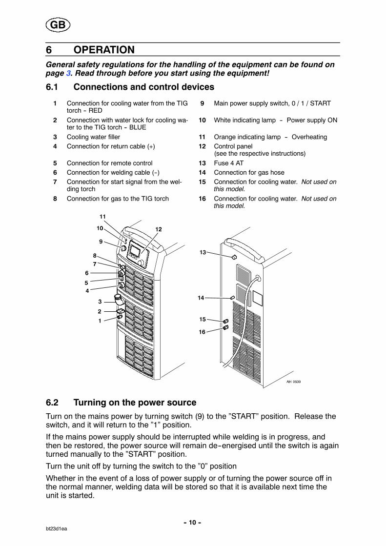
6.1 Connections and control devices
1 Connection for cooling water from the TIGtorch -- RED
9 Main power supply switch, 0 / 1 / START
2 Connection with water lock for cooling wa-ter to the TIG torch -- BLUE
10 White indicating lamp -- Power supply ON
3 Cooling water filler 11 Orange indicating lamp -- Overheating4 Connection for return cable (+) 12 Control panel
(see the respective instructions)5 Connection for remote control 13 Fuse 4 AT6 Connection for welding cable (--) 14 Connection for gas hose7 Connection for start signal from the wel-
ding torch15 Connection for cooling water. Not used on
this model.8 Connection for gas to the TIG torch 16 Connection for cooling water. Not used on
this model.
6.2 Turning on the power sourceTurn on the mains power by turning switch (9) to the ”START” position. Release theswitch, and it will return to the ”1” position.
If the mains power supply should be interrupted while welding is in progress, andthen be restored, the power source will remain de--energised until the switch is againturned manually to the ”START” position.
Turn the unit off by turning the switch to the ”0” position
Whether in the event of a loss of power supply or of turning the power source off inthe normal manner, welding data will be stored so that it is available next time theunit is started.
GB
-- 11 --bt23d1ea
6.3 Fan control
The power source fans continue to run for 6,5 minutes after welding has stopped,and the unit switches to energy--saving mode. They start again when weldingrestarts.
The fans run at reduced speed for welding currents up to 144 A, and at full speed forhigher currents.
6.4 Overheating protection
The power source has two thermal overload trips which operate if the internaltemperature becomes too high, interrupting the welding current and lighting theorange indicating lamp on the front of the unit. They reset automatically when thetemperature has fallen.
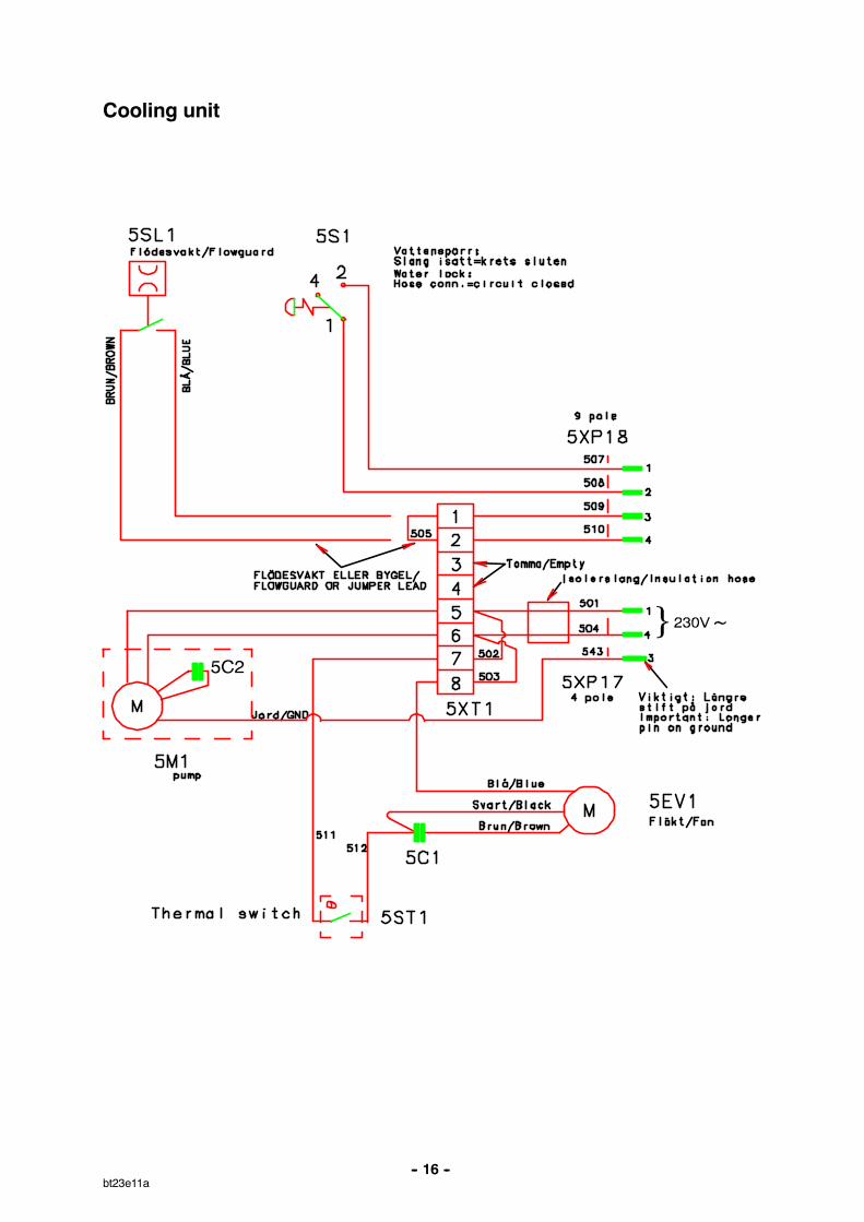
6.5 Cooling unit
Water lock
The cooling unit has a water lock that senses whether the cooling water hoses areconnected.
The power source On/Off switch must be in the “0” position (Off) when connecting awater--cooled TIG torch.
If a water--cooled TIG torch is connected, the water pump starts automatically whenthe main On/Off switch is turned to ”START” and/or when welding starts. Afterwelding, the pump continues to run for 6,5 minutes, and then switches to theenergy--saving mode.
Function when welding
To start welding, the welder presses the torch trigger switch. The power sourceenergises the torch and starts wire feed and the cooling water pump.
To stop welding, the welder releases the torch trigger switch. The welding current isinterrupted, but the cooling water pump continues to run for 6,5 minutes, after whichthe unit switches to energy--saving mode.
Water flow guard
The water flow guard interrupts the welding current in the event of loss of coolant,and displays an error message on the control panel. The water flow guard is anaccessory.
6.6 Remote control unitAristo machines with intergral control panels should have program version 1.21 orhigher, in order for the remote control to function correctly.
When the remote control unit is connected, the power source and wire feed unit arein remote control mode; the buttons and knobs are blocked. The functions can onlybe adjusted via the remote unit.
If the remote control unit is not to be used, the remote control unit must bedisconnected from the power source / wire feed unit, as otherwise it will remain inremote control mode.
GB
-- 12 --bt23d1ea
When carrying out TIG welding, the value for the pulse current can be changed withthe remote control.
For more information about the operation of the remote control unit, see the relevantoperating instructions for the control panel.
7 MAINTENANCE
Regular maintenance is important for safe, reliable operation.
Only those persons who have appropriate electrical knowledge (authorizedpersonnel) may remove the safety plates to connect or carry out service,maintenance or repair work on welding equipment.
Note!All guarantee undertakings from the supplier cease to apply if the customer himselfattempts any work in the product during the guarantee period in order to rectify anyfaults.
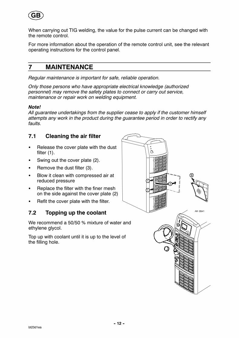
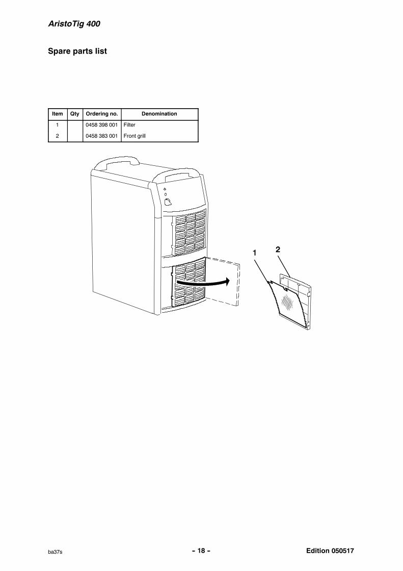
7.1 Cleaning the air filter
S Release the cover plate with the dustfilter (1).
S Swing out the cover plate (2).
S Remove the dust filter (3).
S Blow it clean with compressed air atreduced pressure
S Replace the filter with the finer meshon the side against the cover plate (2)
S Refit the cover plate with the filter.
7.2 Topping up the coolant
We recommend a 50/50 % mixture of water andethylene glycol.
Top up with coolant until it is up to the level ofthe filling hole.
GB
-- 13 --bt23d1ea
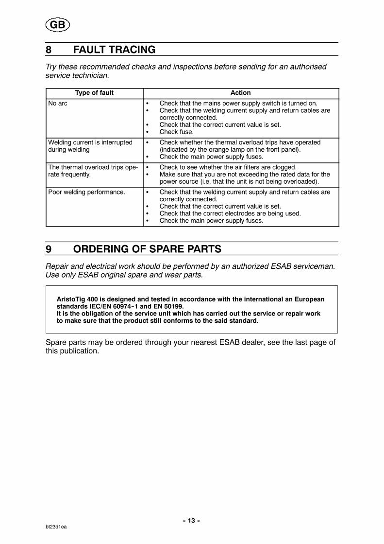
8 FAULT TRACING
Try these recommended checks and inspections before sending for an authorisedservice technician.
Type of fault Action
No arc S Check that the mains power supply switch is turned on.S Check that the welding current supply and return cables are
correctly connected.S Check that the correct current value is set.S Check fuse.
Welding current is interruptedduring welding
S Check whether the thermal overload trips have operated(indicated by the orange lamp on the front panel).
S Check the main power supply fuses.
The thermal overload trips ope-rate frequently.
S Check to see whether the air filters are clogged.S Make sure that you are not exceeding the rated data for the
power source (i.e. that the unit is not being overloaded).
Poor welding performance. S Check that the welding current supply and return cables arecorrectly connected.
S Check that the correct current value is set.S Check that the correct electrodes are being used.S Check the main power supply fuses.
9 ORDERING OF SPARE PARTS
Repair and electrical work should be performed by an authorized ESAB serviceman.Use only ESAB original spare and wear parts.
AristoTig 400 is designed and tested in accordance with the international an Europeanstandards IEC/EN 60974--1 and EN 50199.It is the obligation of the service unit which has carried out the service or repair workto make sure that the product still conforms to the said standard.
Spare parts may be ordered through your nearest ESAB dealer, see the last page ofthis publication.
GB
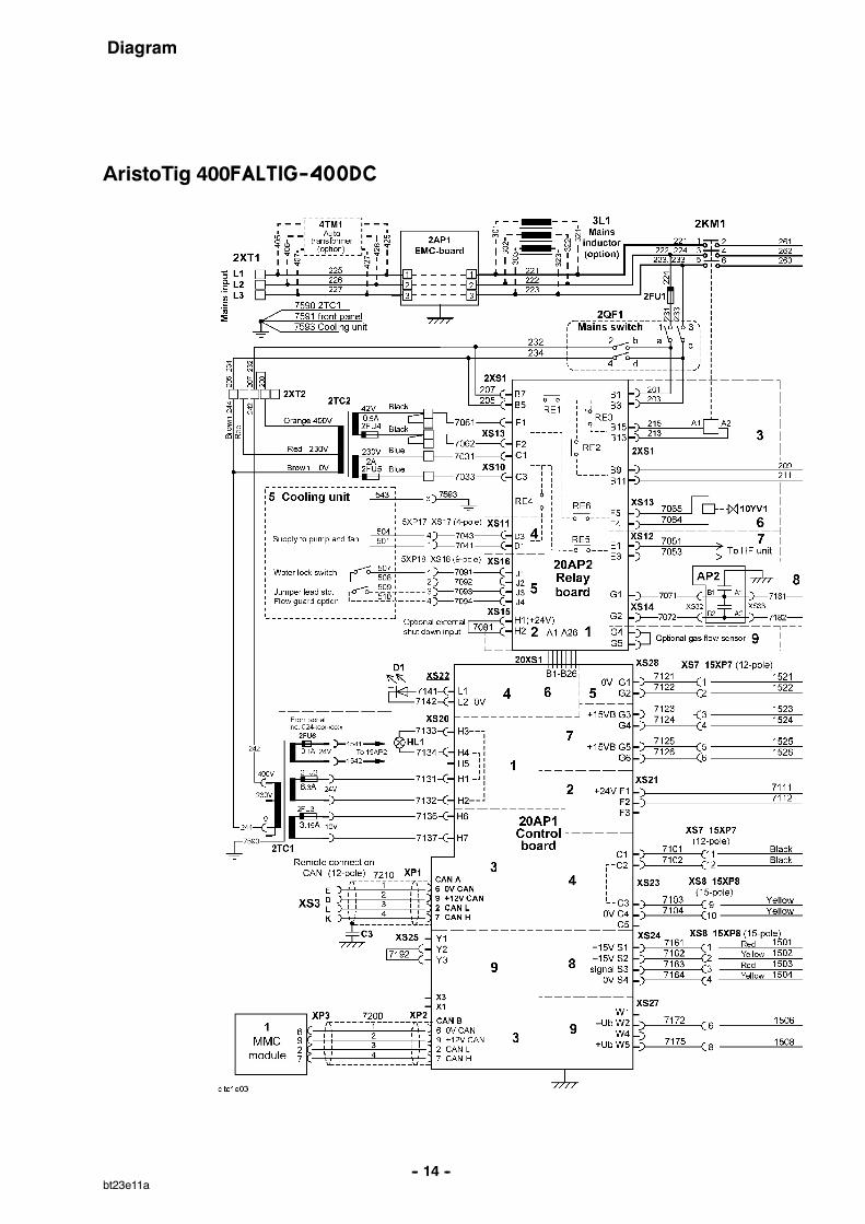
Diagram
-- 14 --bt23e11a
AristoTig 400FALTIG-400DC
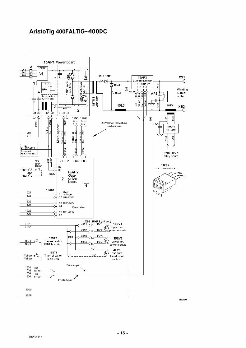
-- 15 --bt23e11a
AristoTig 400FALTIG-400DC
-- 16 --bt23e11a
Cooling unit

AristoTig 400
Edition 050517
Ordering number
-- 17 --bt23o11a
1.
Ordering no. Denomination Type Notes
0458 630 880 Welding power source AristoTig 400 with T4 control panel0458 630 881 Welding power source AristoTig 400 with T4 control panel and cooling unit0458 630 882 Welding power source AristoTig 400 with T4 control panel and auto transformer0458 630 883 Welding power source AristoTig 400 with T4 control panel, cooling unit and
auto transformer0458 630 884 Welding power source AristoTig 400 with T6 control panel0458 630 885 Welding power source AristoTig 400 with T6 control panel and cooling unit0458 630 886 Welding power source AristoTig 400 with T6 control panel and auto transformer0458 630 887 Welding power source AristoTig 400 with T6 control panel, cooling unit and
auto transformer
0458 640 990 Spare part list AristoTig 400
The spare parts list is available on the Internet at www.esab.comUnder ”Products” and ”Welding & cutting equipment”, you will find a link to the page where you canboth search for and download instruction manuals and spare parts lists.
AristoTig 400
Edition 050517
Spare parts list
-- 18 --ba37s
Item Qty Ordering no. Denomination
1 0458 398 001 Filter
2 0458 383 001 Front grill
Edition 050517
AristoTig 400
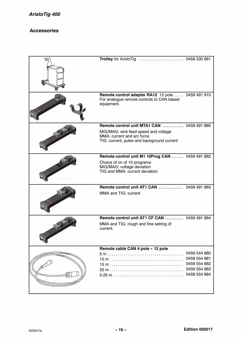
Accessories
-- 19 --bt23a11a
Trolley for AristoTig . . . . . . . . . . . . . . . . . . . . . . 0458 530 881
Remote control adapter RA12 12 pole . . . .For analogue remote controls to CAN basedequipment.
0459 491 910
Remote control unit MTA1 CAN . . . . . . . . . .MIG/MAG: wire feed speed and voltageMMA: current and arc forceTIG: current, pulse and background current
0459 491 880
Remote control unit M1 10Prog CAN . . . . . .Choice of on of 10 programsMIG/MAG: voltage deviationTIG and MMA: current deviation
0459 491 882
Remote control unit AT1 CAN . . . . . . . . . . . .MMA and TIG: current
0459 491 883
Remote control unit AT1 CF CAN . . . . . . . . .MMA and TIG: rough and fine setting ofcurrent.
0459 491 884
Remote cable CAN 4 pole -- 12 pole5 m . . . . . . . . . . . . . . . . . . . . . . . . . . . . . . . . . . . . .10 m . . . . . . . . . . . . . . . . . . . . . . . . . . . . . . . . . . . .15 m . . . . . . . . . . . . . . . . . . . . . . . . . . . . . . . . . . . .25 m . . . . . . . . . . . . . . . . . . . . . . . . . . . . . . . . . . . .0.25 m . . . . . . . . . . . . . . . . . . . . . . . . . . . . . . . . . .
0459 544 8800459 554 8810459 554 8820459 554 8830459 554 884
Edition 050517
AristoTig 400
-- 20 --bt23a11a
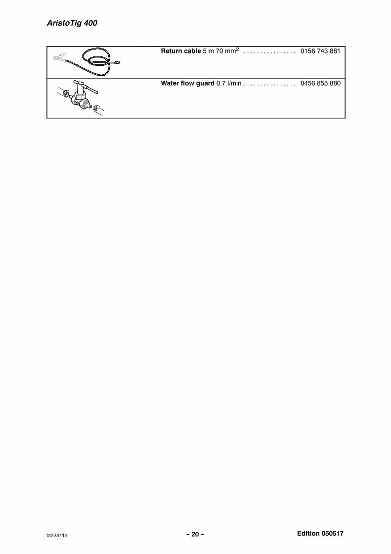
Return cable 5 m 70 mm2 . . . . . . . . . . . . . . . . 0156 743 881
Water flow guard 0.7 l/min . . . . . . . . . . . . . . . . 0456 855 880

-- 21 --p
ESAB ABSE--695 81 LAXÅSWEDENPhone +46 584 81 000
www.esab.com
041227
ESAB subsidiaries and representative offices
EuropeAUSTRIAESAB Ges.m.b.HVienna--LiesingTel: +43 1 888 25 11Fax: +43 1 888 25 11 85
BELGIUMS.A. ESAB N.V.BrusselsTel: +32 2 745 11 00Fax: +32 2 745 11 28
THE CZECH REPUBLICESAB VAMBERK s.r.o.PragueTel: +420 2 819 40 885Fax: +420 2 819 40 120
DENMARKAktieselskabet ESABCopenhagen--ValbyTel: +45 36 30 01 11Fax: +45 36 30 40 03
FINLANDESAB OyHelsinkiTel: +358 9 547 761Fax: +358 9 547 77 71
FRANCEESAB France S.A.Cergy PontoiseTel: +33 1 30 75 55 00Fax: +33 1 30 75 55 24
GERMANYESAB GmbHSolingenTel: +49 212 298 0Fax: +49 212 298 218
GREAT BRITAINESAB Group (UK) LtdWaltham CrossTel: +44 1992 76 85 15Fax: +44 1992 71 58 03
ESAB Automation LtdAndoverTel: +44 1264 33 22 33Fax: +44 1264 33 20 74
HUNGARYESAB KftBudapestTel: +36 1 20 44 182Fax: +36 1 20 44 186
ITALYESAB Saldatura S.p.A.Mesero (Mi)Tel: +39 02 97 96 81Fax: +39 02 97 28 91 81
THE NETHERLANDSESAB Nederland B.V.UtrechtTel: +31 30 2485 377Fax: +31 30 2485 260
NORWAYAS ESABLarvikTel: +47 33 12 10 00Fax: +47 33 11 52 03
POLANDESAB Sp.zo.o.KatowiceTel: +48 32 351 11 00Fax: +48 32 351 11 20
PORTUGALESAB LdaLisbonTel: +351 8 310 960Fax: +351 1 859 1277
SLOVAKIAESAB Slovakia s.r.o.BratislavaTel: +421 7 44 88 24 26Fax: +421 7 44 88 87 41
SPAINESAB Ibérica S.A.Alcalá de Henares (MADRID)Tel: +34 91 878 3600Fax: +34 91 802 3461
SWEDENESAB Sverige ABGothenburgTel: +46 31 50 95 00Fax: +46 31 50 92 22
ESAB International ABGothenburgTel: +46 31 50 90 00Fax: +46 31 50 93 60
SWITZERLANDESAB AGDietikonTel: +41 1 741 25 25Fax: +41 1 740 30 55
North and South AmericaARGENTINACONARCOBuenos AiresTel: +54 11 4 753 4039Fax: +54 11 4 753 6313
BRAZILESAB S.A.Contagem--MGTel: +55 31 2191 4333Fax: +55 31 2191 4440
CANADAESAB Group Canada Inc.Missisauga, OntarioTel: +1 905 670 02 20Fax: +1 905 670 48 79
MEXICOESAB Mexico S.A.MonterreyTel: +52 8 350 5959Fax: +52 8 350 7554
USAESAB Welding & Cutting ProductsFlorence, SCTel: +1 843 669 44 11Fax: +1 843 664 57 48
Asia/PacificCHINAShanghai ESAB A/PShanghaiTel: +86 21 5308 9922Fax: +86 21 6566 6622
INDIAESAB India LtdCalcuttaTel: +91 33 478 45 17Fax: +91 33 468 18 80
INDONESIAP.T. ESABindo PratamaJakartaTel: +62 21 460 0188Fax: +62 21 461 2929
JAPANESAB JapanTokyoTel: +81 3 5296 7371Fax: +81 3 5296 8080
MALAYSIAESAB (Malaysia) Snd BhdShah Alam SelangorTel: +60 3 5511 3615Fax: +60 3 5512 3552
SINGAPOREESAB Asia/Pacific Pte LtdSingaporeTel: +65 6861 43 22Fax: +65 6861 31 95
SOUTH KOREAESAB SeAH CorporationKyungnamTel: +82 55 269 8170Fax: +82 55 289 8864
UNITED ARAB EMIRATESESAB Middle East FZEDubaiTel: +971 4 887 21 11Fax: +971 4 887 22 63
Representative officesBULGARIAESAB Representative OfficeSofiaTel/Fax: +359 2 974 42 88
EGYPTESAB EgyptDokki--CairoTel: +20 2 390 96 69Fax: +20 2 393 32 13
ROMANIAESAB Representative OfficeBucharestTel/Fax: +40 1 322 36 74
RUSSIA--CISESAB Representative OfficeMoscowTel: +7 095 937 98 20Fax: +7 095 937 95 80
ESAB Representative OfficeSt PetersburgTel: +7 812 325 43 62Fax: +7 812 325 66 85
DistributorsFor addresses and phonenumbers to our distributors inother countries, please visit ourhome page
www.esab.com