04399717
TRANSCRIPT

282 IEEE TRANSACTIONS ON POWER ELECTRONICS, VOL. 23, NO. 1, JANUARY 2008
Attenuation of Conducted EMI EmissionsFrom an Inverter-Driven Motor
Hirofumi Akagi, Fellow, IEEE, and Takayuki Shimizu
Abstract—This paper provides theoretical and experimentaldiscussions on conducted electromagnetic interference (EMI)emissions from an inverter-driven motor rated at 400 V and15 kW. It focuses on a line EMI filter and its combination witha motor EMI filter, along with their effects on attenuation ofconducted emission voltage. When no EMI filter is connected,the motor drive cannot meet the conducted emission limits pre-scribed by Category 3 in the IEC61800-3 regulations. The reasonis that the common-mode voltage generated by a voltage-sourcepulse width modulation (PWM) inverter causes a common-modeleakage current flowing into the ground wire lead through par-asitic capacitors inside the motor. When the line EMI filter isconnected, the motor drive can meet Category 3. The motor EMIfilter eliminates the common-mode voltage from the motor ter-minals, thus bringing a drastic reduction to the leakage current.The combination of the two EMI filters can comply with the limitsprescribed by Category 2, which are much stricter than those byCategory 3.
Index Terms—Electromagnetic interference (EMI), leakage cur-rents, motor drives, pulsewidth modulation (PWM) inverters.
I. INTRODUCTION
AN adjustable-speed motor drive by a voltage-sourcepulsewidth modulation (PWM) inverter has made a
significant contribution to achieving energy conservation, aswell as to improving system performance and productivity.However, the PWM inverter based on switching operation hasbeen considered as a representative noise source of conductedand radiated electromagnetic interference (EMI) emissions.The conducted emission may interfere with other electronicequipment through power lines, while the radiated emissionmay bring malfunction, particularly to radio-controlled devicesin the vicinity of the noise source.
The international electro-technical commission (IEC) hasprescribed EMI regulations for motor drives on industrialand commercial low-voltage networks. For example, theIEC61800-3 Category 3 provides conducted emission limitsin a frequency range of 150 kHz to 30 MHz for low-voltagemotor drives with a nominal input current of less than 100 Ain an industrial area. The EMI regulations have encouragedpower electronics engineers to do further research on passiveand active EMI filters for mitigating conducted and/or radiatedemissions [1]–[22].
Manuscript received May 6, 2007; revised July 11, 2007. Recommended forpublication by Associate Editor P. Tenti.
The authors are with the Department of Electrical and Electronic Engi-neering, Tokyo Institute of Technology, Tokyo 152-8552, Japan (e-mail:[email protected]).
Digital Object Identifier 10.1109/TPEL.2007.911878
The authors have proposed a passive EMI filter having ac-cess to the ungrounded neutral point of an inverter-driven motor[20]–[22]. To distinguish it from other passive EMI filters, itis referred to as the motor EMI filter in this paper because itis installed between the inverter and the motor. It is promi-nent in using the three-phase star-connected stator windingsas a part of the filter components. This results in making thefilter smaller in size, more effective in attenuation than otherfilter configurations having no access to the motor neutral point.The motor EMI filter can keep both shaft voltage and groundleakage current in check, as a result of eliminating high-fre-quency common-mode voltage from the motor terminals.
This paper evaluates effects of passive EMI filters on attenua-tion of conducted EMI emissions from an inverter-driven motorrated at 400 V and 15 kW. Measurement of conducted emissionvoltages in a frequency range of 150 kHz to 30 MHz is carriedout by using a line-impedance stabilizing network (LISN) and aspectrum analyzer in accordance with CISPR Pub. 16 [5]. Twotypes of filters are designed, constructed, and tested. One is re-ferred to as a line EMI filter because it is installed at the lineside of the motor drive. The line EMI filter meets the conductedemission limits prescribed by Category 3 in the IEC61800-3 reg-ulations. The other is based on a combination of the motor EMIfilter with the line EMI filter. This combination complies withthe conducted emission limits prescribed by Category 2, whichare much stricter than those by Category 3.
II. MEASUREMENT OF CONDUCTED EMISSION
VOLTAGES WHEN THE LINE EMI FILTER IS
DISCONNECTED AND CONNECTED
A. Experimental System Configurations
Fig. 1 shows the experimental system configuration when noEMI filter is connected, while Fig. 2 shows that when a line EMIfilter is connected. A three-phase transformer changesthe 200-V 50-Hz system with -phase grounding in Japan intothe worldwide 400-V 50-Hz system with neutral grounding. Thesecondary of the transformer is connected to a three-phase dioderectifier through a 440-V 30-A LISN (Kyoritsu: KNW-243C)with a frequency band of 9 kHz to 30 MHz. The common-modeinductor H is intentionally installed betweenthe LISN and the diode rectifier. The reason for installationis to prevent an excessive current from flowing into theLISN, thus brings correct measurement of conducted emissionvoltage to a spectrum analyzer (Agilent Technology: E4411B).A three-phase two-level voltage-source PWM inverter is op-erated at a switching frequency of 15 kHz. A 400-V 15-kWfour-pole induction motor with no load is driven at an inverterfrequency of 20 Hz because load conditions produce little effect
0885-8993/$25.00 © 2007 IEEE

AKAGI AND SHIMIZU: ATTENUATION OF CONDUCTED EMI EMISSIONS FROM AN INVERTER-DRIVEN MOTOR 283
Fig. 1. Experimental system when the line EMI filter is disconnected.
Fig. 2. Experimental system when the line EMI filter is connected.
on the waveform of the common-mode voltage generated by thePWM inverter.
The line EMI filter shown in Fig. 2 consists of a common-mode inductor , three differential-mode inductors , threestar-connected bypass capacitors , and a bypass capacitor
. Here, is made of a stack of five ferrite toroidal cores,while uses a single ferrite toroidal core per phase. Both in-ductors have a single turn, thus resulting in simple structure.The combination of and keeps high-frequency differen-tial-mode current from flowing into the three-phase ac mains.
The line EMI filter has flexibility in designing circuit pa-rameters, including key components and , to meetthe conducted emission limits prescribed by Category 3 inthe IEC61800-3 regulations. The larger the capacitance valueof , the better the filtering performance. In addition, thelarger the inductance value of , the better the filteringperformance. However, the capacitance value has a limitationin avoiding malfunction of a protection relay against a funda-mental-frequency (50 Hz) zero-sequence current higher than10 mA. When the three-phase diode rectifier is connected to anac mains with -phase grounding, or a voltage sag occurs in anac mains with neutral grounding, such a 50-Hz zero-sequencecurrent may flow from the ac mains to the ground wire leadthrough . This paper assigned the capacitance value as
F to make the 50-Hz zero-sequence currentlower than 10 mA in the worst case. On the other hand, the in-ductance value has no limitation from a practical point of view,unlike the capacitance value. In an actual system, however, a
compromise or tradeoff between cost and performance existsin designing the inductance value. Hence, this paper assignedthe inductance value as H to meet the conductedemission limits prescribed by Category 3 under the capacitancevalue of F. Increasing the capacitance value of
could be accompanied by decreasing the inductance valueof if no attention were paid to the 50-Hz zero-sequencecurrent.
B. Considerations on Measurement of Conducted EmissionVoltage
The LISN is indispensable for measurement of conductedemission voltage in accordance with CISPR Pub. 16. It isput on a 2 m 2 m metal plane connected to the neutralpoint of the secondary of the transformer. No current is al-lowed to flow on the metal plane. In other words, the deviceunder test (DUT) is prohibited from grounding to the metalplane. The safety ground terminal of the LISN is connectedto the ground terminal of a switchboard in the authors’ lab-oratory. The spectrum analyzer based on average detectionis set as follows: RBW resolution band width kHz,VBW video band width MHz, sweep time s, andaveraging number .
C. Measurement of Conducted Emission Voltages andObservation of Ground Leakage Currents
Fig. 3 shows measured frequency spectra of conducted emis-sion voltages in Figs. 1 and 2. Figs. 4 and 5 show observed wave-

284 IEEE TRANSACTIONS ON POWER ELECTRONICS, VOL. 23, NO. 1, JANUARY 2008
Fig. 3. Conducted emission voltages measured from Figs. 1 and 2.
Fig. 4. Observed waveforms obtained from Fig. 1, where the line EMI filteris disconnected. (a) With a switching frequency-based time scale. (b) With atime-expanded scale.
forms of the common-mode voltage and three leakage currents,where
• is the common-mode voltage appearing at the ac sideof the inverter with respect to the dc-link midpoint ;
• is the ground leakage current flowing out of the motorframe;
• is the ground leakage current flowing into the LISN;• is the leakage current flowing into the heat sink;• is the leakage current flowing into the line EMI filter.
Fig. 5. Observed waveforms obtained from Fig. 2, where the line EMI filter isconnected. (a) With a switching frequency-based time scale. (b) With a time-expanded scale.
When the line EMI filter is disconnected, the conducted emis-sion voltage does not meet the limits prescribed by Category 3 ina frequency range of 150 kHz to 3 MHz. In particular, it exceedsthe limit at 150 kHz by 20 dB, and the limits from 500 kHz to1 MHz by 15 dB. A partial peak around 3 MHz appears in theconducted emission voltage, and the resultant oscillations witha frequency of 3 MHz are observed in the waveforms ofand in Fig. 4(b). This means that the oscillations come fromresonance between stray inductors in the motor and ground wireleads, and parasitic capacitors inside the diode and IGBT mod-ules. The next section makes an intensive discussion on this in-teresting phenomenon. The conducted emission voltage in a fre-quency band higher than 4 MHz meets Category 3 with a marginof 10 dB.
When the line EMI filter is connected, the conducted emis-sion voltage complies with Category 3 in a frequency range of150 kHz to 30 MHz, as shown in Fig. 3. Moreover, the wave-forms of and in Fig. 5(b) show that the oscillations at

AKAGI AND SHIMIZU: ATTENUATION OF CONDUCTED EMI EMISSIONS FROM AN INVERTER-DRIVEN MOTOR 285
Fig. 6. Common-mode circuit equivalent to Fig. 1 at 150 kHz.
3 MHz are mitigated to some extent. In addition, the line EMIfilter brings sharp attenuation to a frequency band of 650 kHzto 750 kHz as a result of series resonance between and astray inductor of the filter wire lead. The next section gives atheoretical discussion on the sharp attenuation.
Fig. 4(a) suggests that the peak and rms values of are1.78 A and 0.48 A, whereas those of are 1.49 A and 0.52 A,although the waveform of is similar to that of . Thedifference between and results in , where the peakand rms values of are 0.8 A and 0.09 A.
III. EQUIVALENT COMMON-MODE CIRCUITS AT 150 kHz
This section discusses effects of the line EMI filter on atten-uation of the conducted emission voltage at 150 kHz that is thelowest frequency in the frequency band prescribed by the IECregulations. However, the 150-kHz emission voltage may be themost difficult frequency component to comply with the limits.
A. When the Line EMI Filter is Disconnected
Fig. 6 depicts an equivalent circuit for common-modevoltage and current at 150 kHz to Fig. 1. Here, andare the common-mode inductance and resistance values ofthe common-mode inductor , and and are thecommon-mode capacitance and resistance values between thethree-phase motor terminals connected together and the motorframe (the stator case). Note that , , , andare parasitic capacitance values between the diode and IGBTmodules and the heat sink [21]. The use of the LISN enablesto consider the background system impedance upstream of
as the parallel circuit of and at 150 kHz, where avoltage appearing across is just the conductedemission voltage. Although , , and are thestray inductance values of their individual wire leads, they aresmall enough to be neglected at that frequency. The parasiticcapacitance values in Fig. 6 are not theoretical but measuredones at 150 kHz by an LCR meter. The common-mode voltageproduced by the PWM inverter has a fundamental componentwith the same frequency as 15 kHz (switching frequency) andmany harmonic components, including a 150-kHz component.Fig. 6 considers only the 150-kHz component as . More-over, the three-phase diode rectifier produces a common-mode
voltage with a frequency of 150 Hz (triple line frequency).However, this 150-Hz common-mode voltage has no effect onthe conducted emission voltage.
Fig. 6 identifies the following common-mode leakage currentloops:1
• Loop 1:motor ground lead
heat-sink ground lead parasitic capacitors
• Loop 2:motor ground lead
supply ground leadFig. 6 gives the following impedance to each path:
The ratio of with respect to is given by
(1)
This equation suggests that almost no current flows in , sothat is nearly equal to . The assumption ofenables to neglect Loop 1. This makes simple the ratio ofwith respect to at 150 kHz:
(2)
On the other hand, the waveform of includes high-fre-quency components, because the impedance of Loop 1 gets low
1Strictly speaking, the other Loop exists; v ) 3C )
heat-sink ground lead ) supply ground wire lead ) v . How-ever, this loop is negligible because the impedance of 3C is 2.6 k at 150kHz, whereas the impedance of C ==R is 69 at that frequency.

286 IEEE TRANSACTIONS ON POWER ELECTRONICS, VOL. 23, NO. 1, JANUARY 2008
Fig. 7. Common-mode circuit equivalent to Fig. 2 at 150 kHz.
in a range of higher than 1 MHz. In fact, an oscillating com-ponent with a frequency of 3 MHz is included in the wave-form of , as shown in Fig. 4(b). This oscillating componentcomes from a series resonance of , , , andin Loop 1. The resonant frequency can be calculated fromFig. 6 as follows:
MHz (3)
This frequency is nearly equal to the oscillating frequency of.
B. When the Line EMI Filter is Connected
Fig. 7 depicts an equivalent circuit for common-mode voltageand current at 150 kHz to Fig. 2. Note that and are theinductance and resistance values of the common-mode inductor
, , and are those of the differential-mode inductor, and is the stray inductance value of the filter wire lead.
Fig. 7 identifies the following common-mode leakage currentloops.
• Loop 1:motor ground lead
heat-sink ground lead parasitic capacitors
• Loop 2:motor ground lead
supply ground lead
• Loop 3:motor ground lead
filter leadThe impedance of is much higher than the series
impedance of , , , and at 150 kHz. Thus,Loop 1 can be neglected from Fig. 7. The existence of the line
EMI filter divides into Loops 2 and 3. Fig. 7 gives thefollowing impedance to each filter path:
The rms values of and have the following relation:
(4)
The use of expresses as
(5)
Substituting (5) into (4) yields the ratio of with respect toas
(6)
where
Let in (6) be , and moreover let in(2) be . The ratio of with re-spect to expresses a factor of attenuation ofcommon-mode current at 150 kHz, as
dB (7)
The measured factor of attenuation, obtained from Fig. 3,is 22 dB with a difference from (7) by 8 dB. The reasons

AKAGI AND SHIMIZU: ATTENUATION OF CONDUCTED EMI EMISSIONS FROM AN INVERTER-DRIVEN MOTOR 287
Fig. 8. Experimental system when both line and motor EMI filters are connected.
why the difference appears are as follows. One comes from fre-quency dependence of the passive components used in this ex-periment, along with measurement errors in the component pa-rameters. Another is that the theoretical factor of attenuation,given by (7), excludes an effect of differential-mode current onthe conducted emission voltage. Note that the conducted emis-sion voltage measured by the LISN and the spectrum analyzerincludes both common-mode and differential-mode currents.Unfortunately, it would be impossible to separate the common-mode current from the differential-mode current in the experi-mental system of Fig. 2.
Equation (6) suggests that sharp attenuation occurs at a fre-quency of
(8)
This means that the line EMI filter acts as a notch filter aroundthat frequency. It is easy to calculate (8) as kHz fromthe two parameters of and in Fig. 7. This theoret-ical frequency agrees well with an experimental frequency of700 kHz, around which sharp attenuation occurs in the con-ducted emission voltage of Fig. 3.
IV. MEASUREMENT OF CONDUCTED EMISSION VOLTAGE
WHEN BOTH LINE AND MOTOR EMI FILTERS ARE CONNECTED
Although the line EMI filter can prevent high-frequencyleakage current from flowing into the LISN, it cannot mitigatethe common-mode voltage produced by the inverter and the en-suing leakage current flowing out of the motor. The motor EMIfilter proposed in [20]–[22] can eliminate the common-modevoltage from the motor terminals, thus leading to a significantreduction in . As a result, the combination of the lineand motor EMI filters is expected to attenuate the conductedemission voltage, particularly in a frequency range of 150 to600 kHz.
A. System Configuration
Fig. 8 shows the experimental system configuration in whichboth line and motor EMI filters are connected. The motor EMIfilter consists of a -reduction filter and a common-mode
filter. The -reduction filter consists of three differen-tial-mode inductors , three damping resistors , and threestar-connected capacitors , forming a low-pass filter tomitigate the rate of voltage change to time at the motor termi-nals. The common-mode filter forms a current loop from thecommon-mode inductor , the three-phase motor terminalsand the ungrounded motor neutral point to the dc-link mid-point through a series-connected resistor and capacitor
. This current loop helps effectively in applyingthe common-mode voltage produced by the inverter across thecommon-mode inductor , so that no common-mode voltageappears at the motor terminals [20]. The 4.7-nF capacitor ,that is connected between the heat sink and the dc-link mid-point, has the function of bypassing the high-frequency leakagecurrent flowing out of the heat sink into the dc-link midpoint,as discussed later on.
The line EMI filter in Fig. 8 is the same as that in Fig. 2 exceptfor the differential-mode inductor H , to enhanceattenuation of differential-mode current.
B. Conducted Emission Voltage and Leakage Currents
Fig. 9 shows the measured result of conducted emissionvoltage in the case of using both line and motor EMI filtersand turning the switch on, in comparison to that in thecase of using only the line EMI filter, along with the limitsprescribed by Categories 3 and 2. Note that low-voltage motordrives should comply with Category 3 in an industrial area orCategory 2 in a commercial area.
Fig. 10 shows observed waveforms of the common-modevoltage appearing at the motor terminals, , and the fourleakage currents, where (a) is the case of disconnecting the4.7-nF capacitor (the switch is turned off), and (b) is thecase of connecting it (the switch is turned on).
It is clear from Fig. 9 that the combination of the line EMIfilter with the motor EMI filter produces an excellent attenuationeffect on the conducted emission voltage in a wide range of 150kHz to 10 MHz, thus resulting in complying with Category 2.In particular, the motor EMI filter achieves attenuation by 20dB in a range of 150 to 400 kHz. This results from a significantreduction in . However, no attenuation occurs in a
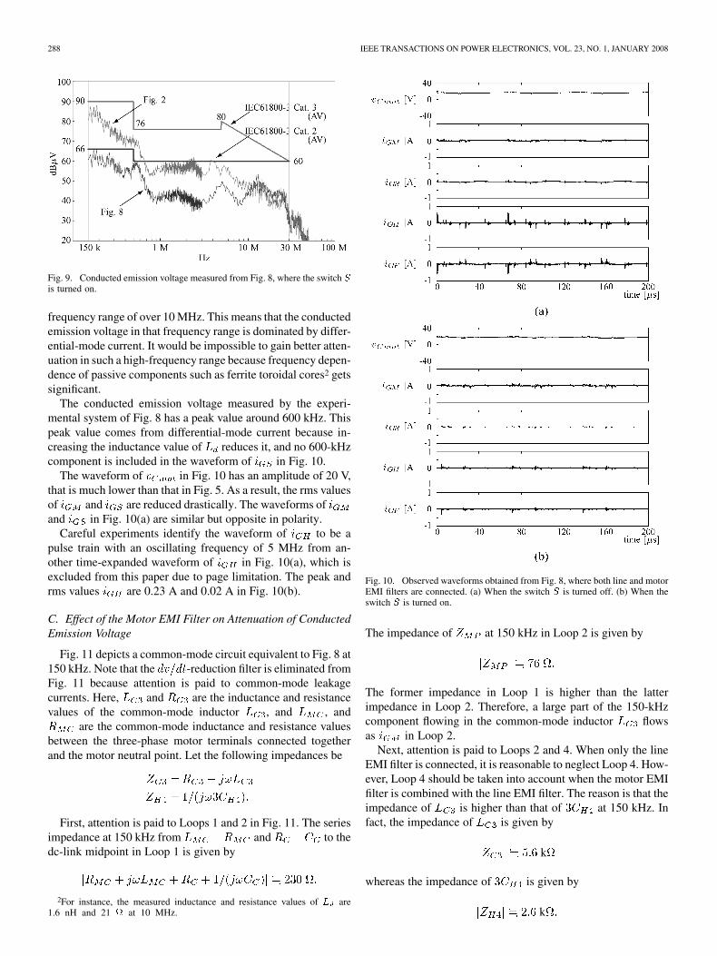
288 IEEE TRANSACTIONS ON POWER ELECTRONICS, VOL. 23, NO. 1, JANUARY 2008
Fig. 9. Conducted emission voltage measured from Fig. 8, where the switch Sis turned on.
frequency range of over 10 MHz. This means that the conductedemission voltage in that frequency range is dominated by differ-ential-mode current. It would be impossible to gain better atten-uation in such a high-frequency range because frequency depen-dence of passive components such as ferrite toroidal cores2 getssignificant.
The conducted emission voltage measured by the experi-mental system of Fig. 8 has a peak value around 600 kHz. Thispeak value comes from differential-mode current because in-creasing the inductance value of reduces it, and no 600-kHzcomponent is included in the waveform of in Fig. 10.
The waveform of in Fig. 10 has an amplitude of 20 V,that is much lower than that in Fig. 5. As a result, the rms valuesof and are reduced drastically. The waveforms ofand in Fig. 10(a) are similar but opposite in polarity.
Careful experiments identify the waveform of to be apulse train with an oscillating frequency of 5 MHz from an-other time-expanded waveform of in Fig. 10(a), which isexcluded from this paper due to page limitation. The peak andrms values are 0.23 A and 0.02 A in Fig. 10(b).
C. Effect of the Motor EMI Filter on Attenuation of ConductedEmission Voltage
Fig. 11 depicts a common-mode circuit equivalent to Fig. 8 at150 kHz. Note that the -reduction filter is eliminated fromFig. 11 because attention is paid to common-mode leakagecurrents. Here, and are the inductance and resistancevalues of the common-mode inductor , and , and
are the common-mode inductance and resistance valuesbetween the three-phase motor terminals connected togetherand the motor neutral point. Let the following impedances be
First, attention is paid to Loops 1 and 2 in Fig. 11. The seriesimpedance at 150 kHz from and to thedc-link midpoint in Loop 1 is given by
2For instance, the measured inductance and resistance values of L are1.6 nH and 21 at 10 MHz.
Fig. 10. Observed waveforms obtained from Fig. 8, where both line and motorEMI filters are connected. (a) When the switch S is turned off. (b) When theswitch S is turned on.
The impedance of at 150 kHz in Loop 2 is given by
The former impedance in Loop 1 is higher than the latterimpedance in Loop 2. Therefore, a large part of the 150-kHzcomponent flowing in the common-mode inductor flowsas in Loop 2.
Next, attention is paid to Loops 2 and 4. When only the lineEMI filter is connected, it is reasonable to neglect Loop 4. How-ever, Loop 4 should be taken into account when the motor EMIfilter is combined with the line EMI filter. The reason is that theimpedance of is higher than that of at 150 kHz. Infact, the impedance of is given by
k
whereas the impedance of is given by
k

AKAGI AND SHIMIZU: ATTENUATION OF CONDUCTED EMI EMISSIONS FROM AN INVERTER-DRIVEN MOTOR 289
Fig. 11. Common-mode circuit equivalent to Fig. 8 at 150 kHz.
TABLE IMEASURED PEAK AND RMS VALUES OF i , i , AND i
Y: meet, N: not meet
When Loops 2 and 4 are taken into account, the ratio ofwith respect to is given by
(9)
The ratio of (9) with respect to (6), defined by ,results in an effect of the motor EMI filter on attenuation of theconducted emission voltage
dB (10)
The attenuation factor obtained from Fig. 9 is 22 dB, thusproducing a difference by 9 dB between theoretical and exper-imental values. This difference comes from an effect of bothdifferential-mode current and frequency dependence of passivecomponents on the experimental value, as already described inSection III-B.
D. Effect of the Capacitor on Attenuation of
The motor EMI filter can reduce drastically, as shownin Fig. 10(a). However, it could not mitigate the common-modeleakage current circulating as around Loop 4 through theparasitic capacitor , the heat sink and the line EMI filter,if the capacitor were disconnected from Fig. 11 (the switch
were turned off). Note that the positive direction of Loop 4 inFig. 11 is opposite to that of in Fig. 8. Recalling that theoscillating frequency of is 5 MHz enables to calculate the
impedance of the three parallel-connected parasitic capacitorsas 50 at 5 MHz.
Connecting the 4.7-nF capacitor between the heat sinkand the dc-link midpoint (turning the switch on) presents alow-impedance path to Loop 3, where the impedance of is6.8 at 5 MHz. The impedance of is one-seventh as lowas the impedance of . As a result, a largepart of the high-frequency common-mode current flowing in
circulates around Loop 3 through the capacitor . Thus,connecting the capacitor makes a considerable contributionto reducing the peak and rms values of .
Table I summarizes the peak and rms values of , ,and , and whether each of the three filter configurations,including connection and disconnection of the capacitor ,meets the IEC61800-3 regulations. Although the line EMI filtermakes the conducted emission voltage meet Category 3, it in-creases the peak and rms values of . The combination of theline EMI filter with the motor EMI filter can reduce the peak andrms values of and so drastically as to make the con-ducted emission voltage meet Category 2.
V. CONCLUSION
This paper has focused on attenuation of conducted EMIemissions from an inverter-driven motor rated at 400 V and15 kW. Two types of passive EMI filters have been designed,constructed, and tested. One is a line EMI filter placed at theline side of the motor drive, and the other is a motor EMIfilter installed at the motor side. This paper has measured theconducted emission voltage of the motor drive in accordance

290 IEEE TRANSACTIONS ON POWER ELECTRONICS, VOL. 23, NO. 1, JANUARY 2008
with CISPR Pub. 16. The contributions of this paper can besummarized as follows.
• The use of the line EMI filter has complied with the limitsprescribed by Category 3 in the IEC61800-3 regulations.
• The combination of the line EMI filter with the motor EMIfilter has complied with the limits prescribed by Category2, which are much stricter than those by Category 3.
• Common-mode circuits equivalent to the motor drive haveprovided intensive discussions about effects of the line andmotor EMI filters on attenuation of both conducted emis-sion voltages and ground leakage currents.
From a practical point of view, it is important to discuss andverify the effectiveness of the EMI filter configuration presentedin Fig. 8 (having the switch turned on), when the filter config-uration is applied to motor drives with different current ratings,but with the same voltage rating as 400 V. The authors under-stand that optimal filter parameters for the different current rat-ings lie close to the filter parameters presented in Fig. 8, becauseconducted emission voltages depend mainly on the motor (ordc-link) voltage. However, careful measurement and evaluationare left as future work to verify the authors’ understanding.
REFERENCES
[1] Y. Murai, T. Kubota, and Y. Kawase, “Leakage current reduction fora high-frequency carrier inverter feeding an induction motor,” IEEETrans. Ind. Applicat., vol. 28, no. 4, pp. 858–863, Jul./Aug. 1992.
[2] S. Ogasawara and H. Akagi, “Modeling and damping of high-fre-quency leakage currents in PWM inverter-fed ac motor drive systems,”IEEE Trans. Ind. Applicat., vol. 32, no. 5, pp. 1105–1114, Sep./Oct.1996.
[3] S. Ogasawara, H. Ayano, and H. Akagi, “Measurement and reductionof EMI radiated by a PWM inverter-fed ac motor drive system,” IEEETrans. Ind. Applicat., vol. 33, no. 4, pp. 1019–1026, Jul./Aug. 1997.
[4] I. Takahashi, A. Ogata, H. Kanazawa, and A. Hiruma, “Active EMIfilter for switching noise of high frequency inverters,” in Proc. IEEJ/IEEE-IAS PCC, Aug. 1977, pp. 331–334.
[5] R. W. Gubisch, “The measurement of emissions (methods and instru-mentation),” Compliance Eng. Eur. Edition, pp. 46–55, Jan./Feb. 1998.
[6] P. T. Finlason, “Output filters for PWM drives with induction motors,”IEEE Ind. Applicat. Soc. Mag., vol. 4, no. 1, pp. 46–52, Jan./Feb. 1998.
[7] L. Ran, S. Gokani, J. Clare, K. J. Bradley, and C. Christopoulos, “Con-ducted electromagnetic emissions in induction motor drive systemspart I: Time domain analysis and identification of dominant models,”IEEE Trans. Power Electron., vol. 13, no. 4, pp. 757–767, Jul. 1998.
[8] L. Ran, S. Gokani, J. Clare, K. J. Bradley, and C. Christopoulos, “Con-ducted electromagnetic emissions in induction motor drive systemspart I: Frequency domain models,” IEEE Trans. Power Electron., vol.13, no. 4, pp. 768–776, Jul. 1998.
[9] S. Ogasawara, H. Ayano, and H. Akagi, “An active circuit for cancel-lation of common-mode voltage generated by a PWM inverter,” IEEETrans. Power Electron., vol. 13, no. 5, pp. 835–841, Sep. 1998.
[10] A. Julian, G. Oriti, and T. Lipo, “Elimination of common-mode voltagein three-phase sinusoidal power converters,” IEEE Trans. Power Elec-tron., vol. 14, no. 5, pp. 982–989, Sep. 1999.
[11] L. Rossetto, P. Tenti, and A. Zuccato, “Electromagnetic compatibilityissues in industrial equipment,” IEEE Ind. Applicat. Soc. Mag., vol. 5,no. 6, pp. 34–46, Nov./Dec. 1999.
[12] G. L. Skibinski, R. J. Kerkman, and D. W. Schlegel, “EMI emissionsof modern PWM ac drives,” IEEE Ind. Applicat. Soc. Mag., vol. 5, no.6, pp. 47–81, Nov./Dec. 1999.
[13] M. M. Swamy, K. Yamada, and T. Kume, “Common mode current at-tenuation techniques for use with PWM drives,” IEEE Trans. PowerElectron., vol. 16, no. 2, pp. 248–255, Mar. 2001.
[14] T. G. Habetler, R. Naik, and T. A. Nondahl, “Design and implementa-tion of an inverter output LC filter for dv=dt reduction,” IEEE Trans.Power Electron., vol. 17, no. 3, pp. 327–331, May 2002.
[15] A. Kempski, R. Smolenski, and R. Strzelecki, “Common mode cur-rent paths and their modeling in PWM inverter-fed drives,” in Proc.IEEE-IAS Ann. Meeting, Oct. 2002, pp. 1551–1556.
[16] Y. C. Son and S. K. Sul, “Conducted EMI in PWM inverter for house-hold electric appliance,” IEEE Trans. Power Electron., vol. 38, no. 5,pp. 1370–1379, Sep./Oct. 2002.
[17] Y. C. Son and S. K. Sul, “A new active common-mode filter for PWMinverter,” IEEE Trans. Power Electron., vol. 18, no. 6, pp. 1309–1314,Nov. 2003.
[18] H. Akagi, H. Hasegawa, and T. Doumoto, “Design and performanceof a passive EMI filter for use with a voltage-source PWM inverterhaving sinusoidal output voltage and zero common-mode voltage,”IEEE Trans. Power Electron., vol. 19, no. 4, pp. 1069–1076, Jul. 2004.
[19] N. Hanigovszki, J. Landkildehus, G. Spiazzi, and F. Blaabjerg, “AnEMC evaluation of the use of unshielded motor cables in ac adjustablespeed drive application,” IEEE Trans. Power Electron., vol. 21, no. 1,pp. 273–281, Jan. 2006.
[20] H. Akagi and T. Doumoto, “An approach to eliminating high-fre-quency shaft voltage and leakage current from an inverter-drivenmotor,” IEEE Trans. Ind. Applicat., vol. 40, no. 4, pp. 1162–1169,Jul./Aug. 2004.
[21] H. Akagi and T. Doumoto, “A passive EMI filter for preventing high-frequency leakage current from flowing through the inverter heat sinkof an adjustable-speed motor drive system,” IEEE Trans. Ind. Applicat.,vol. 41, no. 5, pp. 1215–1223, Sep./Oct. 2005.
[22] H. Akagi and S. Tamura, “A passive EMI filter for eliminating bothbearing current and ground leakage current from an inverter-drivenmotor,” IEEE Trans. Power Electron., vol. 21, no. 5, pp. 1459–11469,Sep. 2006.
Hirofumi Akagi (M’87–SM’94–F’96) was bornin Okayama, Japan, on August 19, 1951. He re-ceived the B.S. degree from the Nagoya Instituteof Technology, Nagoya, Japan, in 1974, and theM.S. and Ph.D. degrees from the Tokyo Instituteof Technology, Tokyo, Japan, in 1976 and 1979,respectively, all in electrical engineering.
In 1979, he was with the Nagaoka University ofTechnology, Nagaoka, Japan, as an Assistant and thenAssociate Professor in the Department of ElectricalEngineering. In 1987, he was a Visiting Scientist at
the Massachusetts Institute of Technology (MIT), Cambridge, for ten months.From 1991 to 1999, he was a Professor in the Department of Electrical Engi-neering, Okayama University, Okayama, Japan. From March to August of 1996,he was a Visiting Professor at the University of Wisconsin, Madison, and thenMIT. Since January 2000, he has been a Professor in the Department of Elec-trical And Electronic Engineering, Tokyo Institute of Technology. He has madepresentations many times as a keynote or invited speaker internationally. Hehas published more than 70 IEEE journal/transactions papers, including twoinvited papers published in Proceedings of the IEEE in 2001 and 2005. Ac-cording to Google Scholar, the total citation index for all his papers is morethan 5000. His research interests include power conversion systems, ac motordrives, active and passive EMI filters, high-frequency resonant-inverters for in-duction heating and corona discharge treatment processes, and utility applica-tions of power electronics such as active filters, self-commutated BTB systems,and FACTS devices.
Dr. Akagi is currently the President of the IEEE Power Electronics Society.He was elected as a Distinguished Lecturer of the IEEE Power electronicsand Industry Applications Societies for 1998–1999. He received two IEEETRANSACTIONS ON INDUSTRY APPLICATIONS Prize Paper Awards in 1991and 2004, and two IEEE TRANSACTIONS ON POWER ELECTRONICS PrizePaper Awards in 1999 and in 2003, nine IEEE Industry Applications SocietyCommittee Prize Paper Awards, the IEEE William E. Newell Power ElectronicsAward in 2001, and the IEEE Industry Applications Society OutstandingAchievement Award in 2004.
Takayuki Shimizu was born in Annaka, Japan, on6 May 1982. He received the B.S degree from theTechnical College of Gunma, Gunma, Japan, and theM.S. degree from the Tokyo Institute of Technology,Tokyo, Japan, in 2005 and 2007, respectively, both inelectrical engineering.
He is working for Toshiba Mitsubishi-Electric In-dustrial Systems Corporation (TMEIC).