02b - uml
TRANSCRIPT
Version 2.0
CSC565
UNIFIED MODELING LANGUAGE (UML)
SOFTWARE ENGINEERING - LAB
WHAT IS UML?
UML stands for Unified Modeling LanguageA language (notation) for modeling object-oriented systems.A standard maintained by the Object Management Group (OMG).A modeling language which has 13(++) diagrams.Means for visualizing, specifying, constructing and documenting software systems.
http://www.uml.org
WHAT IS UML?
The UML combines the best of the best fromData Modeling concepts (Entity Relationship Diagrams)Business Modeling (work flow)Object ModelingComponent Modeling
The UML is the standard language for visualizing, specifying, constructing, and documenting the artifacts of a software-intensive systemIt can be used with all processes, throughout the development life cycle, and across different implementation technologies
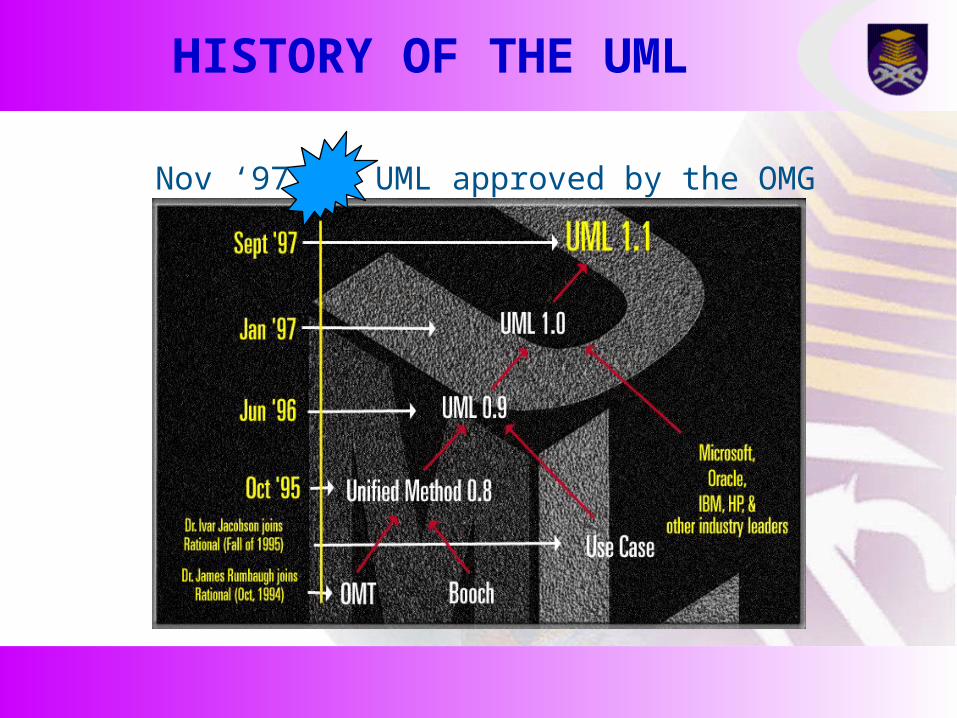
HISTORY OF THE UML
Nov ‘97 UML approved by the OMG

UML… THE LONG STORY

UML SUPPORTS APPLICATION DEVELOPMENT
Classesapplication partitioning
Business ObjectsRelationships
Business Process
Objects
Use Cases
large scale system
ScenariosComponentsMicrosoft
ActiveX/COMMicrosoft
ORDBMSOracle
CORBAOMG

UML CONCEPTS
The UML may be used toDisplay the boundary of a system & its major functions using use cases and actorsIllustrate use case realizations with interaction diagramsRepresent a static structure of a system using class diagramsModel the behavior of objects with state transition diagramsReveal the physical implementation architecture with component & deployment diagrams Extend functionality with stereotypes

UML DIAGRAMS – PART I

UML DIAGRAMS – PART II
Diagram DescriptionLearning Priority
Activity Diagram Depicts high-level business processes, including data flow, or to model the logic of complex logic within a system.
High
Class Diagram Shows a collection of static model elements such as classes and types, their contents, and their relationships. High
Communication Diagram
Shows instances of classes, their interrelationships, and the message flow between them. Communication diagrams typically focus on the structural organization of objects that send and receive messages. Formerly called a Collaboration Diagram.
Low
Component Diagram
Depicts the components that compose an application, system, or enterprise. The components, their interrelationships, interactions, and their public interfaces are depicted.
Medium
Composite Structure Diagram
Depicts the internal structure of a classifier (such as a class, component, or use case), including the interaction points of the classifier to other parts of the system.
Low
Deployment Diagram
Shows the execution architecture of systems. This includes nodes, either hardware or software execution environments, as well as the middleware connecting them.
Medium
Interactive Overview Diagram
A variant of an activity diagram which overviews the control flow within a system or business process. Each node/activity within the diagram can represent another interaction diagram.
Low
Object Diagram Depicts objects and their relationships at a point in time, typically a special case of either a class diagram or a communication diagram.
Low
Package Diagram Shows how model elements are organized into packages as well as the dependencies between packages. Low
Sequence Diagram Models the sequential logic, in effect the time ordering of messages between classifiers. High
State Machine Diagram
Describes the states an object or interaction may be in, as well as the transitions between states. Formerly referred to as a state diagram, state chart diagram, or a state-transition diagram.
Medium
Timing Diagram Depicts the change in state or condition of a classifier instance or role over time. Typically used to show the change in state of an object over time in response to external events.
Low
Use Case Diagram Shows use cases, actors, and their interrelationships. Medium
refer to: http://www.agilemodeling.com/essays/umlDiagrams.htm

APPLYING UML…

UML’S VIEW MODELS
A view model or viewpoints framework is a framework which defines a coherent set of views to be used in the construction of a system architecture, software architecture or enterprise architecture .A view is a representation of a whole system from the perspective of a related set of certain concerns.View model provides guidance and rules for structuring, classifying, and organizing system architectures.

NOMINAL VIEW MODELS
In “Framework for Modeling Space Systems Architectures”, Peter Shames and Joseph Skipper (2006) define nominal view as a list of possible modeling viewpoints.
Enterprise ViewpointInformation ViewpointFunctional ViewpointPhysical ViewpointEngineering ViewpointTechnology Viewpoint

ENTERPRISE ARCHITECTURE VIEW MODELS
Enterprise Architecture framework defines how to organize the structure and views associated with an enterprise architecture.Since the enterprise architecture can be large and complex, the models produced tend to be large and complex.To manage these scale and complexity, an Architecture Framework provides tools, methods and guidelines.
Zachman FrameworkRM-ODP ViewsDoDAF ViewsFederal Enterprise Architecture Views

GENERIC VIEW MODELS
Three Schema Approach – an approach to build information systems and systems information management that promotes the conceptual model as the key to achieve data integration.
External schema for user viewsInternal schema that defines physical storage structuresConceptual schema integrates internal and external schemas
GENERIC VIEW MODELS
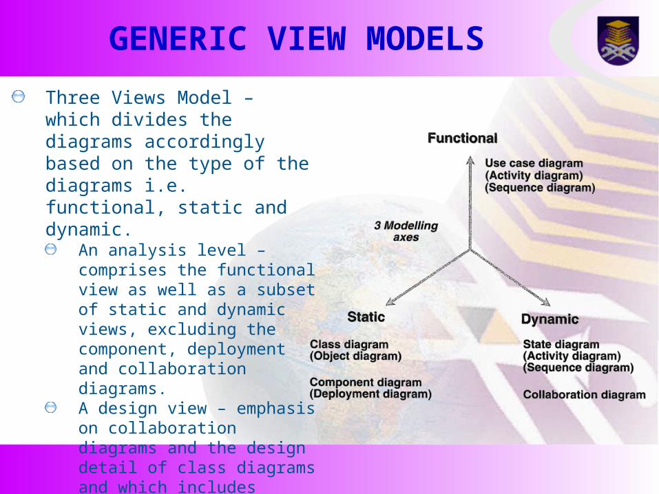
Three Views Model – which divides the diagrams accordingly based on the type of the diagrams i.e. functional, static and dynamic.
An analysis level – comprises the functional view as well as a subset of static and dynamic views, excluding the component, deployment and collaboration diagrams.A design view – emphasis on collaboration diagrams and the design detail of class diagrams and which includes component diagrams and deployment diagrams.
GENERIC VIEW MODELS
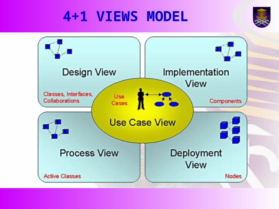
4+1 is a view model designed by Philippe Kruchten in 1995 for describing the architecture of software-intensive systems, based on the use of multiple, concurrent views
Logical view : is concerned with the functionality that the system provides to end-users. Development view : illustrates a system from a programmers perspective and is concerned with software managementProcess view : deals with the dynamic aspect of the system, explains the system processes and how they communicate, and focuses on the runtime behaviour of the system.Physical view : depicts the system from a system engineer's point-of-view. It is concerned with the topology of software components on the physical layer, as well as communication between these components
In addition selected use cases or scenarios are utilized to illustrate the architecture. Hence the model contains 4+1 views.
4+1 VIEWS MODEL
4+1 VIEWS MODEL
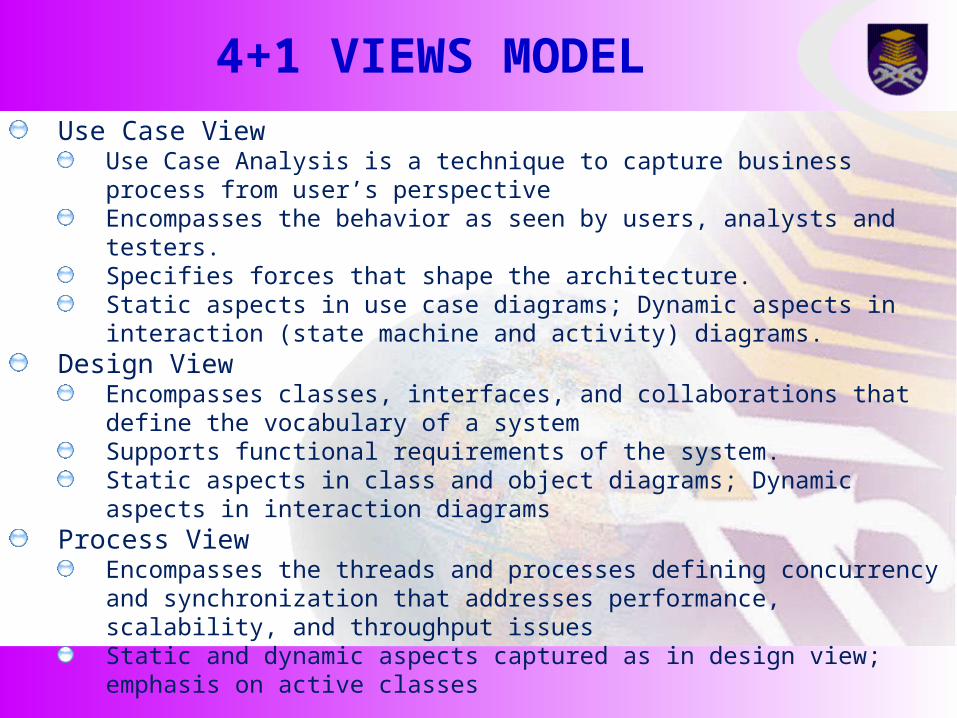
Use Case ViewUse Case Analysis is a technique to capture business process from user’s perspectiveEncompasses the behavior as seen by users, analysts and testers.Specifies forces that shape the architecture.Static aspects in use case diagrams; Dynamic aspects in interaction (state machine and activity) diagrams.
Design ViewEncompasses classes, interfaces, and collaborations that define the vocabulary of a systemSupports functional requirements of the system.Static aspects in class and object diagrams; Dynamic aspects in interaction diagrams
Process ViewEncompasses the threads and processes defining concurrency and synchronization that addresses performance, scalability, and throughput issuesStatic and dynamic aspects captured as in design view; emphasis on active classes

4+1 VIEWS MODEL
Implementation ViewEncompasses components and files used to assemble and release a physical systemAddresses configuration management.Static aspects in component diagrams; Dynamic aspects in interaction diagrams
Deployment ViewEncompasses the nodes that form the system hardware topology Addresses distribution, delivery, and installation Static aspects in deployment diagrams; Dynamic aspects in interaction diagrams

RULES OF UML
Well formed models — semantically self-consistent and in harmony with all its related models Semantic rules for
Names — what you can call things Scope — context that gives meaning to a name Visibility — how names can be seen and used Integrity — how things properly and consistently relate to one another Execution — what it means to run or simulate a dynamic model
Avoid models that are Elided — certain elements are hidden for simplicity Incomplete — certain elements may be missing Inconsistent — no guarantee of integrity
PROCESS FOR USING UML
Use case driven — use cases are primary artifact for defining behavior of the system Architecture-centric — the system’s architecture is primary artifact for conceptualizing, constructing, managing, and evolving the system Iterative and incremental — managing streams of executable releases with increasing parts of the architecture included

APPLYING UML…

A SIMPLIFIED VERSION

Thank You