020 instrument performance characteristics.pdf
TRANSCRIPT

InstrumentTypes
andPerfo
rmance
Characteristics
17Mar
15
Que
stions
Howistheaccuracy
ofan
instrumen
tusuallydefin
ed?
Whatisthe
diffe
rencebe
tweenaccuracy
andprecision
?To
illustratethedynamiccharacteristicso
fthe
following:
(a)zeroorde
rinstrum
ent
(b)firstorde
rinstrum
ent
(c)secon
dorde
rinstrum
ent
Atungsten
resistancethermom
eter
with
arangeof
–270
Cto
+1100Chasa
quoted
inaccuracy
of1.5%
offullscale
reading.Whatisthe
likelymeasuremen
terror
whe
nitis
readingatempe
rature
of950C?
3
InstrumentT
ypes
PassiveandActiveInstruments
instrumento
utpu
tisp
rodu
ced
entirelyby
thequ
antitybe
ing
measured
thequ
antitybe
ingmeasured
simplymod
ulates
themagnitude
ofsomeexternalpo
wer
source.
In a
ctiv
e in
stru
men
ts, t
he
exte
rnal
pow
er s
ourc
e is
us
ually
in e
lect
rica
l for
m,
but
in s
ome
case
s, it
can
be o
ther
form
s of
ene
rgy,
such
as
a pn
eum
atic
or
hydr
aulic
one
.5
NullTypeandDe
flectionType
Instruments
defle
ctiontype
instrument
thevalueof
thequ
antitybe
ingmeasuredis
displayedinterm
softhe
amou
ntof
movem
ento
fapo
inter.
nulltype
instrument
pressure
measurementism
adein
term
softhe
valueof
theweights
need
edto
reachthisnu
llpo
sition
Ingene
ral,nu
lltype
instrumentsaremoreaccurate
than
defle
ctiontype
s,bu
tdeflectiontype
instrument
isclearly
moreconven
ient
6

Analogue
andDigitalInstrum
ents
Analogue
Instrumen
tsou
tput
that
varie
scon
tinuo
uslyas
thequ
antitybe
ingmeasured
changes
DigitalInstrum
ents
output
that
varie
sindiscrete
step
sandso
canon
lyhave
afin
itenu
mbe
rofvalue
s.
7
Indicatin
gInstrumentsandInstrumentswith
aSignal
Outpu
t
Indicatin
gInstruments
Instrumentswith
aSignalOutpu
t
Instrumen
tsthat
have
asig
naltypeou
tput
areused
common
lyas
partof
automaticcontrolsystems.
8
StaticCh
aracteristicso
fInstrum
ents
Accuracy
ofmeasurementisthu
sone
considerationinthe
choice
ofinstrumentfor
aparticular
application.
Other
parameters,such
assensitivity,linearity,andthe
reactio
nto
ambienttem
perature
changes,arefurthe
rconsiderations.
Values
quoted
forinstrum
entcharacteristicsinsuch
adata
sheeto
nlyapplywhe
ntheinstrumentisu
sedun
derspe
cifie
dstandard
calibratio
ncond
ition
s.
9
Data
Sheet(Example)
10

Accuracy
Anindicatoro
fhow
closetheou
tput
readingof
the
instrumen
tistothecorrectvalue
.measuremen
tuncertainty,inaccuracy
Percentage
ofthefullscale(f.s.)reading
ofan
instrument
ifwearemeasurin
gpressuresw
ithexpe
cted
values
betw
een0and
1bar,wewou
ldno
tuse
onewith
ameasuremen
trange
of0–10
bar.
Exam
ple
11
Precision
/Rep
eatability/Re
prod
ucibility
spread
ofreadings
ofthesamequ
antity.
Repe
atability:closene
ssof
output
readings
with
constant
measuremen
tcon
ditio
ns.
Reprod
ucibility:closene
ssof
output
readings
with
varying
measuremen
tcon
ditio
ns.
12
Tolerance
themaxim
umerrorthatistobe
expe
cted
insomevalue.
Whe
nused
correctly,tolerance
describ
esthemaxim
umde
viation
ofamanufacturedcompo
nent
from
somespecified
value.
Exam
ple
13
Range(Span)
andLine
arity
Range
theminim
umandmaxim
umvalues
ofaqu
antitythat
theinstrumentis
desig
nedto
measure
Line
arity
Non
linearityisde
fined
asthemaxim
umde
viationof
anyof
theou
tput
readings
markedofrom
thisstraight
lineandisusually
expressedas
ape
rcen
tage
offullscalereading.
14

Sensitivity
ameasure
ofthechange
ininstrumento
utpu
tthato
ccurs
whe
nthequ
antitybe
ingmeasuredchangesb
yagivenam
ount.
theslo
peof
thestraight
lineof
bestfit
Exam
ple
15
Threshold,
Dead
SpaceandHy
steresisEffect
Threshold
Theminim
umlevelofinp
utleadstoachange
intheinstrumen
toutpu
t
Dead
space
therangeof
diffe
rent
inpu
tvalues
over
which
there
isno
change
inou
tput
value.
Hysteresiseffects
Diffe
rent
characteristicsfor
increasin
gandde
creasin
gcaseso
fmeasurin
g.magne
tichysteresis:
instrumen
tsthat
containelectricalwindingsformed
roun
dan
ironcore.
16
Summaryof
nonlinearties
17
Resolutio
nandEffectso
fDisturbance
Resolutio
nalower
limiton
themagnitude
ofthechange
intheinpu
tmeasured
quantitythat
prod
uces
anob
servablechange
intheinstrumento
utpu
t.
Effectso
fDisturbance
Allcalibratio
nsandspecificatio
nsof
aninstrumen
tare
onlyvalid
unde
rcontrolledcond
ition
softem
perature,pressure,andso
on.The
sestandard
ambien
tcon
ditio
nsareusually
defin
edintheinstrumen
tspe
cification.
zero
drift
(bias)
sensitivity
drift
18

Effectso
fDisturbance
19
Exam
ple:Zero
Drift
20
Exam
ple:Zero
Drift
+Sensitivity
Drift
21
Characteristicso
fInstrum
ents
22
Thestaticcharacteristicso
fmeasurin
ginstrumentsare
concerne
don
lywith
thesteady
statereadingthat
the
instrumentsettle
sdow
nto,suchas
accuracy
ofthereading.
Thedynamiccharacteristicso
fameasurin
ginstrument
describ
eits
behavior
inthetim
eintervalbefore
the
instrumentreaches
asteady
valueinrespon
se.

StaticRe
spon
seCh
aracterization
MeasurementInstrum
ents
are
notp
erfect:steadystate(static)
andtransie
nt(dynam
ic).
Calibratio
n:to
obtainthe
relatio
nbe
tweenthemeasured
varia
bleandinstrumento
utpu
tvaria
ble.
Type
sofcalibratio
ns:static
and
dynamic
Sensitivity:thesm
allestchange
inaqu
antitythat
aninstrument
cande
tect
Stat
ic c
alib
ratio
n cu
rve
23
Calibratio
nAccuracy
Absolute
error:
Relativeerror:
Calibratio
naccuracy:
whe
nthecharacteristicso
fthe
instrumentw
illhave
drifted
from
thestandard
specificatio
nby
anun
acceptableam
ount.
Whe
nthissituatio
nisreache
d,itisne
cessaryto
recalibrate
theinstrumentb
ackto
standard
specificatio
ns.
24
Exam
ple
25
Solutio
n
U
E2
26Sign
ifica
nt fi
gure
s =
3

Inpractice,thereisatim
ede
layandam
plitu
dediffe
rencebe
tween
themeasuredvalueandtrue
valuefortim
evaryinginpu
tvariableat
agiventim
e.Thisdiffe
renceisreferred
toas
thedynamicerror.
Ingene
ral,thedynamicrespon
seof
ameasuremen
tinstrum
entcan
bede
scrib
edby
azero,1
stor
2ndorde
rsystem.
DynamicRe
spon
seCh
aracterization
27
30 s
< 1
s
3
min
utes
Descrip
tionof
DynamicBe
haviou
r
28
Timeinvaria
ntmeasurin
gsystem
,
Zero
orde
r:
Firsto
rder:
Second
orde
r:
Inpu
t
0
1
2
Introd
uctio
nto
MatlabandSimulink
29
Hel
p ic
onW
indo
w fo
r in
tera
ctiv
e co
mm
ands
Clic
king
the
Sim
ulin
kic
onTo
sta
rt

New
file
Simulinkforclassical
controlsystem
analysis
Cre
atin
g a
New
Mod
el
Sele
ct t
he o
bjec
tive
blo
ck in
the
Si
mul
ink
Libr
ary
Bro
wse
r, th
en
drag
it t
o th
e m
odel
win
dow
.
To a
dd b
lock
s to
you
r m
odel
Con
nect
ing
Blo
cks
in t
he M
odel
Win
dow
1.Po
sitio
n th
e m
ouse
poi
nter
ove
r an
inpu
t/ o
utpu
t po
rt.
2.D
rag
a lin
e fr
om t
he in
put/
outp
ut p
ort
to a
des
ired
outp
ut/in
put
port
(pre
ss a
nd h
old
the
left
butt
on, d
rag
and
rele
ase)
.N
ote
that
the
poi
nter
cha
nges
to
a cr
oss
hair
s (+
) sha
pe
whi
le o
ver
the
port

To w
eld
a co
nnec
tion
to
an
exis
ting
line
:(D
raw
ing
a B
ranc
h Li
ne)
1.Po
sitio
n th
e m
ouse
poi
nter
on
the
line.
2.D
rag
a lin
e fr
om t
he d
esire
d po
int
usin
g th
e ri
ght
mou
se b
utto
n.
set
sim
ulat
ion
opti
ons
such
as
the
star
t an
d st
op t
ime,
and
the
typ
e of
sol
ver
that
Sim
ulin
kso
ftw
are
uses
to
solv
e th
e m
odel
at
each
ti
me
step
. You
spe
cify
the
se
opti
ons
usin
g th
e C
onfig
urat
ion
Para
met
ers
dial
og b
ox.
Dou
ble-
clic
k th
e Sc
ope
bloc
k in
the
m
odel
win
dow
. The
Sco
pe w
indo
w
disp
lays
the
sim
ulat
ion
resu
lts.
Figure
Scop
eEdito
r

Outpu
tyisdirectlyrelativeto
inpu
tF(t)b
yconstant
gaina 0
Exam
ple:
anelectricalresistancestraingage
aninpu
tstraindirectlycauses
achange
inthe
gage
resistance
DynamicTimeRe
spon
se(zeroorde
r)
39
ForF
(t)b
eing
astep
functio
nof
unitAandy(0)
=y 0
DynamicTimeRe
spon
se(1
storde
r)
40
Dynamicof
aThermom
eter
Thefirstlawof
thermod
ynam
ics
Energy
stored
with
intheliquid=convectivehe
atthansfer
41
Determ
inesystem
timeconstant
bystep
respon
se
Steady
stategain:accuracy
Timeconstant:respo
nsetim
efor
data
measuremen
t(2%
errort
s=
4)
42
ByLaplacetransform
t:tim
econstant
K:system
gain
()
()
1K
Ys
Fs
s

Exam
ple
43
x=5t,T x=10
–0.05
t
Solutio
n
44
/(
)1
tL
es
2
2
2 2
((
)(0
))(
)(
)1
115
((
)10
)(
)10
0.05
11
(15
1)(
)15
010
0.05
150
100.
05(
)(1
51)
(15
1)(1
51)
11.2
510
.75
0.
()
()
()
05(
)(1
51)
rr
x
rr
rx
rr
r
r
r
tt
tt
tt
Lapl sT
st
Ts
Tac
s
sTs
Ts
ss
sT
ss
s
Ts
ss
ss
eTr
ans
s
T
fo s
rm
ss
s
/15 /1
5
()
0.75
10.7
50.
05
=10
0.75
0.05
(15
)
tr
t
tt
et
et
Tim
eA
ltitu
deTe
mp
Tem
p re
adin
gTe
mp
erro
r0
010
10.0
00
0.00
0 10
509.
59.
865
0.36
5 20
100
99.
552
0.55
2 30
150
8.5
9.14
8 0.
648
4020
08
8.69
8 0.
698
5025
07.
58.
223
0.72
3 10
0050
00-4
0-3
9.25
0 0.
750
Respon
seto
Sinu
soidal
Inpu
tForce
(1storde
rsystem)
45
DynamicError
Phaselag:
radiansa
ndph
aselaginsecond
Dynamicerror
whe
re
Dyn
amic
err
ors
are
func
tion
of fr
eque
ncy
2T
22
Syst
em G
ain
46

DynamicErrord
ueto
PhaseLagandGa
inRatio
n
47
Freq
uencyRe
spon
seForsteadystaterespon
seto
asin
usoidalinp
ut(t
)
Magnitude
plot
Phaseplot
11
13 2c
()
tan
tan
tan
c1
48
Freq
uencyRe
spon
seFor
=1,themagnitude
ratio
neq
uals0.70
7(dynam
icerror
of29
%)and
theph
aseshift
equals45
.Themagnitude
ratio
oftenisexpressedinun
itsof
decibe
ls(dB),w
hich
isoriginated
from
power
ratio
Sincepo
wer
isasquaredqu
antity,De
cibe
lisd
efined
as
210
1PBe
llog
P
49
CutoffFreq
uencyandSystem
Band
width
50

Exam
ple
51
Exam
ple
Solutio
n:Assumption:
E(0)
isthevolta
geou
tput
correspo
ndingto
fluidtempe
rature
att=
0,i.e.,
Uni
t :
mV
Uni
t :
52
Exam
ple(con
t.)Dy
namicerror
Timelag
11
13 2c
()
tan
tan
tan
c1
53
DynamicTimeRe
spon
se(2
ndorde
r)
54

TimeRe
spon
seof
2ndorde
rSystems
55
Characteristic
Equatio
nandTheirR
elationshipto
Damping
56
TimeRe
spon
seof
2ndorde
rSystems
57
TimeRe
spon
seof
2ndorde
rSystems
58

Damping
Ratio
=0Nodamping
<1Und
erdamping
=1Criticaldam
ping
>1Overdam
ping
59
Step
Respon
sePerfo
rmance
Specificatio
n
The
desired
perfo
rmance
characteristicsof
atracking
system
may
bespecified
interm
sof
thetransie
ntrespon
seto
aun
itstep
functio
ninpu
t.Somequ
alities
forevaluatin
gsystem
perfo
rmance
aredefin
edas
follows.For
,(1).Peak
overshoo
t(pe
rcento
foversho
otP.O
.)M
p:M
p=10
0%(y
max–y(
))
1)
(y
60
Step
Respon
sePerfo
rmance
Specificatio
n(2
).pe
aktim
e(ti
me
tom
ax.o
vers
hoot
)tp:
y(t p)
=y m
ax
(3).
freq
uenc
yof
osci
llatio
nof
the
trans
ient
d:1/
(2t p)
Hz
(4).
rise
time
t r:(5
).se
ttlin
gtim
et s:
(6).
time
cons
tant
:,
for
%,
2|1
)(
|st
tt
y9.0
)(
and
1.0)
(,
21
12
ty
ty
tt
t r
368
.0|1
)(
|,t
yt
61
TimeRe
spon
seof
a2n
dOrder
System
with
=0.2
Sett
ling
time
of 2
% is
ge
nera
lly u
sed
in c
ontr
ol
syst
em s
tudy
and
set
tling
tim
e of
10%
may
be
used
in
mea
sure
men
t fie
ld.
62

Relatio
nBe
tweenPo
leLocatio
nto
System
Specificatio
n(stand
ard2n
dorde
rSystem
<0.70
7)
t ne
1
t ne
1
Atthetim
eof
2%errort
s
ns
sn
t
t
te
sn
912
.302.0ln
02.0
dn
pt2
1
%10
0
%10
0)1
)1((
..
21
/e
eO
Pp
nt
63
equivalent
timeconstant:
settlingtim
e(2%e s
s):
whe
reiscalledthedamping
(tim
e)constant.
Dampe
d/rin
ging
freq
uency:
rad/sec
peak
time:
Relatio
nBe
tweenPo
leLocatio
nto
System
Specificatio
n(stand
ard2n
dorde
rSystem
<0.70
7)
dn
nn
nnn
jj
ss
sR
sY
-1
-:po
les
2)
()
(2
22
2
nst
491
2.3
21
npt
1
21
nd
64
01
23
45
60123456
X: 2
Y: 2
.594
X: 0
.500
4Y
: 4.8
14
X: 4
Y: 3
.055
X: 1
Y: 1
.897
Relatio
nBe
tweenPo
leLocatio
nto
System
Specificatio
n(stand
ard2n
dorde
rSystem
<0.70
7)
t p=0.5sec,
d=2
rad/sec=1Hz
t s=3.91
2sec(2%error)
P.O.=
60.5%
Timeconstant
=1sec
dn
nn
nnn
jj
ss
sR
sY
-1
-:po
les
2)
()
(2
22
2 40240
)(
3623
.6,
1572
.0
21
,1
21
,11
2
2
2
ss
sG
n
n
nd
n
2832
.61
:lo
catio
npo
lej
65
Respon
seto
Sinu
soidal
Inpu
tForce
(2ndorde
rsystem)
66
Exam
ple
js
bj
sb
as
ba
sb
sY
* 00
2
2
1
1)
(
jej
Gjj
Gj
ss
Gb
j
js
2)(
2)
()
(0
je
jG
jjG
js
sG
bj
js
2)
(2
)(
)(
* 0
22
)(
)(
ss
Gs
YCo
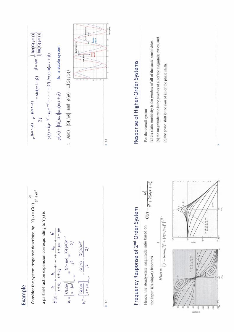
nsider
thesystem
respon
sede
scrib
edby
apartialfractionexpansioncorrespo
ndingto
Y(s)is
67
)si
n()
()(
21
21
tj
Ge
be
bt
yt
at
a
))(
Im(
))(
Re(
tan
1
jG
jG
)si
n()
()
(t
jG
y
)si
n(2
)(
)(
tje
et
jt
j
)(
)(
and
)(
)(
jG
jG
A
for
a st
able
sys
tem
68
Freq
uencyRe
spon
seof
2ndOrder
System
69
Respon
seof
Higher
Order
System
s