02 design considerations for ductile reinforced concrete ... · design considerations for ductile...
TRANSCRIPT

Design considerations for ductile reinforced
concrete columns: Hong Kong case studies
J S Kuang PhD CEng FICE FIStructE FHKIE
The Hong Kong University of Science and Technology
Annual Concrete Seminar 2017
26 April 2017
Hong Kong

Great Challange:�civil infrastructure is vulnerable to earthquakes�
Aftermate of the 1995 Kobe earthquake�
2

1. Introduction�
3
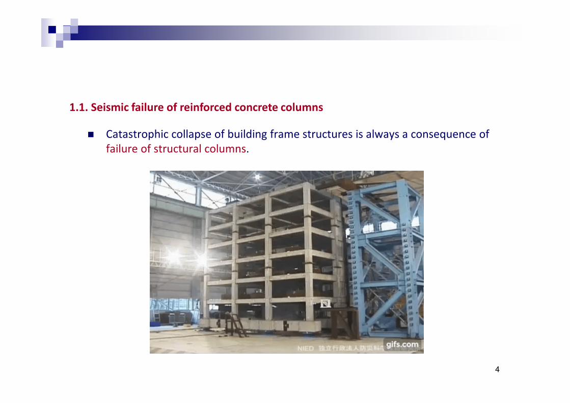
1.1. Seismic failure of reinforced concrete columns
Catastrophic collapse of building frame structures is always a consequence of failure of structural columns.
4

Protecting columns from losing the load-carrying capacity is the most crucial part in the ductility design of RC frame structures to withstand seismic actions,
o which complies with the principles and requirements for the safety and serviceability of structures.
“Pancake” collapse of a masonry infilled RC frame building due to failure of columns in the 1999 İzmit Earthquake, Turkey
5

Seismic failure of columns/bridge piers is often due to high axial load and inadequate transverse reinforcement for concrete confinement and restraint of longitudinal bar against buckling.
Damaged columns of Olive Damage of a poorly confined Damage of viaduct column due to
View Hospital in the 1971 San concrete bridge column in the inadequate confining reinforcement in
Fernando Valley Earthquake 1994 Northridge Earthquake the 2011 Great East Japan Earthquake
6

Curvature ductility factor versus column axial load
1.2. Ductility design of reinforced concrete columns
There are a number of detailing methods for enhancing the ductility of RC columns, where axial compression limits and confinement detailing in critical regions are the most common and effective methods (Park, 1986)
Effect of axial compression
High axial compression
low ductility
level
7

Effect of confinement�
Good confinement�high ductility�
Stress–strain responses of plain concrete (P) and three confined concrete�cross sections (Moehle and Cavanagh, 1985)�
8

The amount of confining reinforcement required by seismic design codes is often much higher for the columns subject to high axial compression in order to compensate the reduced ductility capacity.
Some modern seismic design codes, including Eurocode 8 (EN 1998–1:2004), Chinese Seismic Design Code (GB 50011-2010), Turkish Earthquake Code (TEC 2007), also stipulate upper limits on axial compression ratio v� (ACR), defined as
Column axial load in the seismic design situation
Nd vd =
Acfcd
Column cross-sectional area times the design concrete compressive strength
9

It has been shown that axial compression ratio governs the failure modes (thus the ductility) of RC columns (Fardis, 2009).
RC columns changes from tension-controlled behaviour to compression controlled behaviour approximately at = 胃.l (ACI 318 -14).
10

Different design codes have different provisions on the confinement detailing and axial compression limits, in spite of the same theoretical background.
NOTE. ACI, NZ and HK codes do not explicitly specify the limit on axial compression ratio.�
11

12

1.3 Objectives of study
This study revisits the scientific background of axial compression effect on the structural behaviour of RC columns, complemented with a statistical study for quantification of the ACR effects on the deformation behaviour and lateral strength.
Axial compression ratio (ACR) limits stipulated in different modern seismic design codes are thoroughly discussed and compared.
This study can shed light on finding the most appropriate ductility detailing methods and a suitable ACR limit for controlling the performance of RC columns to use in the developing design code of structures for seismic resistance in Hong Kong.
13

2. Effect of axial force on performance of columns�

2.1. Theoretical background
High axial compression causes early crushing of concrete and lead to low displacement capacity.
It can be illustrated by considering the displacement capacities of RC columns under different axial compression levels.
Separate analyses are performed for flexure-controlled columns and shear-controlled columns: the column aspect ratio
αααα = L /h > 3, flexural controlled, αααα = L /h ≤ 3, shear controlledL s c L s c
where�L5 is the length from the critical section to the point of contraflexure; ℎ is the column depth.c
15

The ultimate displacement Δu of the flexure-controlled columns can be directly calculated by the moment-curvature analysis that gives
Δ ⎛ ε ξε y ⎞ u cu ≥ ξε α /3 + 0.044 f d −
y L y l ⎜ ⎟ L c h
s ⎝ c ⎠
where ξ is a shape factor, which takes a value of 2.1 for rectangular sections and 2.25 for circular sections; εy is the yield strain of steel reinforcement; fy is
the yield strength of longitudinal reinforcement; �z is the longitudinal bar size; c is the depth of neutral axis.
It shows that the ultimate displacement of columns decreases with the increase in the depth of neutral axis c, which increases with axial compression.
16

ACR effects on the ultimate drift ratios (UDRs) for flexural columns with different mechanical volumetric ratios of transverse reinforcement �w = P5fyw/fc
1. ↑ ACR ↓ UDR
2. Low UDR at high ACR
(> 40%)
Calculated ultimate drifts for flexural Comparison between calculated and test
columns subject to different ACRs results (PEER Database)
17

For shear-controlled columns, the ultimate drift can be estimated by the following empirical equation (Elwood & Moehle, 2008)
Δ 1 v 1 P 3 1 u = 4ρ − − + ≥ s 40 A f 100 100 Ls 40 f g cc
where P is the transverse reinforcement ratio A /(bs), where A is the w w w cross-sectional area of transverse reinforcement parallel to the applied lateral load, s is the spacing of the transverse reinforcement and b is the column width; v is nominal shear stress; A9 is the gross cross sectional area; f is the c
measured compressive cylinder strength of unconfined concrete.
According to this equation, lower ultimate drifts of shear columns result in higher ACR as of flexural columns, though it is also recognised that axial compression can increase the friction on the cracked surfaces.
18

ACR effects on the ultimate drift ratios (UDRs) for shear columns with different
mechanical volumetric ratios of transverse reinforcement � = P5 f /fw yw c
1. ↑ ACR ↓ UDR
2. Nearly constant at high
ACR (> 65%)
Calculated ultimate drifts for shear columns subject to different ACRs
Comparison between calculated and test results (PEER Database)
19

On the hand, the lateral load resisting capacity of flexural columns can be calculated as
⎛⎜⎜
⎞⎟⎟
d1
∑ (ε )∫ν = σ , E ε si s ) ⋅ Ai− ( ) ⋅ ( − c + x)dx + min( fb x d sgn si u c yA L g s ⎝ ⎠ic
For shear columns, the positive effect of axial compression on the shear strength of RC columns is reflected in the Sezen model (2002):
⎡ ρ⎢ ⎢⎣
0.4 f Pc ⎤ ⎥ ⎥⎦
ν = k f + 0.5 f AαL c g
yt u s
where�
⎧ ⎪⎨⎪⎩
1.0 µΔ < 2
k = -0.075 1.15 2 ≤ < 6+µ µΔΔ
0.7 µΔ ≥ 6
20

ACR effects on the lateral strength (LS) for flexural columns with different
mechanical volumetric ratios of transverse reinforcement � = P5 f /fw yw c
Calculated lateral strength for flexural columns subject to different ACRs
Behaviour changes from tension
failure to compression failure
Very good agreement
Comparison between calculated and test results (PEER Database)
21
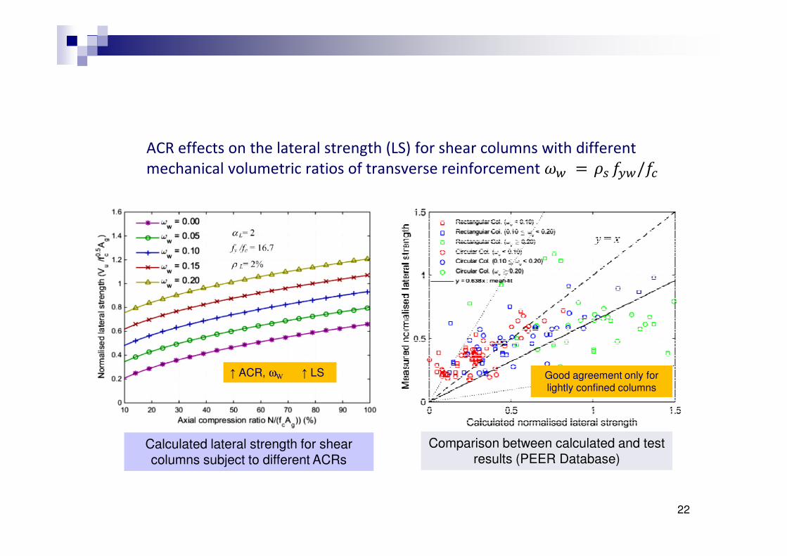
Calculated lateral strength for shear columns subject to different ACRs
↑ ACR, ωW ↑ LS Good agreement only for lightly confined columns
ACR effects on the lateral strength (LS) for shear columns with different
mechanical volumetric ratios of transverse reinforcement � = P5 f /fw yw c
Comparison between calculated and test results (PEER Database)
22

The actual effects of axial compression on RC columns are more complicated and difficult to be modelled accurately.
Beside the reduction of curvature ductility, other typical effects of high axial compression are
1.� leading to early spalling of the concrete cover at relatively low displacement, which in turn increases the buckling risk of the exposed longitudinal bars (Kappos, 1996);
2.� exacerbating the P-Δ effect on the columns in particular the slender ones, which is characterised by “crawling” phenomenon occurring in the hysteretic behaviour and leading to collapse (Paulay & Priestley, 1992);
3.� increase of the risk of low cycle fatigue of the columns under seismic actions (Borg & Rossetto, 2012).
23

2.2. Statistical analysis
The quantification of the concrete confinement and axial compression effects has been very much relying on experimental data and this is normally served as a basis for developing code provisions for practical design.
A statistical analysis is conducted with a large database of 474 experimental data sets of RC columns,
o which is composed of experimental data presented in the Structural Performance Database (Berry et al., 2004),and also some latest test results (Ahn & Shin, 2007; Rodrigues et al., 2013; Kim et al., 2007; Shinha & Roy, 2004; Lee et al., 2013).
24
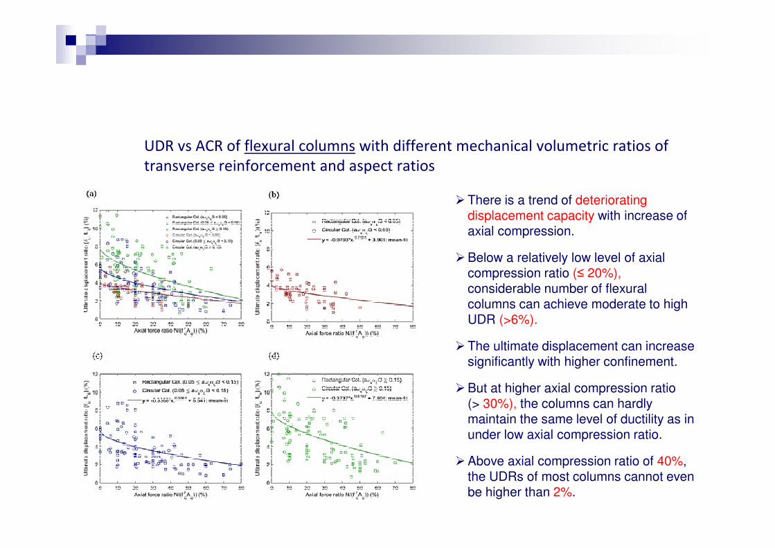
UDR vs ACR of flexural columns with different mechanical volumetric ratios of�transverse reinforcement and aspect ratios�
' There is a trend of deteriorating displacement capacity with increase of axial compression.
' Below a relatively low level of axial compression ratio (≤ 20%), considerable number of flexural columns can achieve moderate to high UDR (>6%).
' The ultimate displacement can increase significantly with higher confinement.
' But at higher axial compression ratio (> 30%), the columns can hardly maintain the same level of ductility as in under low axial compression ratio.
' Above axial compression ratio of 40%, the UDRs of most columns cannot even be higher than 2%.
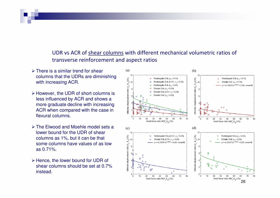
UDR vs ACR of shear columns with different mechanical volumetric ratios of transverse reinforcement and aspect ratios
' There is a similar trend for shear columns that the UDRs are diminishing with increasing ACR.
' However, the UDR of short columns is less influenced by ACR and shows a more graduate decline with increasing ACR when compared with the case in flexural columns.
' The Elwood and Moehle model sets a lower bound for the UDR of shear columns as 1%, but it can be that some columns have values of as low as 0.71%.
' Hence, the lower bound for UDR of shear columns should be set at 0.7% instead.
26

LS vs ACR of flexural columns with different mechanical volumetric ratios of transverse reinforcement and aspect ratios
' Higher amount of confining reinforcement does not significant increase the lateral strength.
' The lateral strength of flexural columns is largely dependent on the amount of longitudinal reinforcement and slenderness.
' Confining reinforcement (ωV) can enhances the crushing strain (i.e. UDR) of concrete by more than 40%-300% (Biskinis, Fardis, 2013), while the confined compressive strength (i.e. LS) can be increased by only 20%-60%.
' The lateral strength of columns increase with decreasing aspect ratios, which is opposite to the relationship between the displacement capacity and aspect ratio.
27

LS vs ACR of shear columns with different mechanical volumetric ratios of transverse reinforcement and aspect ratios
' Higher ACRs lead to noticeable increase in the lateral strength of short columns.
' High axial compression can enhance the friction on the shear crack surfaces.
' With greater amount of confining reinforcement, the lateral strength of the shear columns is also noticeably higher.
' Nevertheless, such increase in lateral strength generally cannot compensate the adverse effect of the reduction in the displacement capacity due to high axial load, which generally dictates the collapse probability of buildings under seismic loading.
28 28

3. Design of Ductile RC Columns�

3. Design recommendations
The stipulated limits on the axial compression ratios in different design codes are compared in adjacent to the statistical analysis presented before.
Flexural columns
30

' The upper bound ACR limits of HK, NZ and ACI codes are a bit way off from a reasonable limit.
' It is noted that the HK code require critical load combinations with other load cases; hence the value of the axial compression may be larger in gravity or wind-controlled structures than the value induced by seismic action.
' EC8 provisions on ACR limits can guarantee the ultimate displacement
ratios of flexure-controlled columns would not be lower than 2.5%, (i.e. Δ� ≥ 1/40L5, provided that column hinges are properly detailed.
31

Shear columns�
32

' Due to the brittle nature of shear-controlled columns, the ultimate displacement ratios are much lower in comparison with the flexure-controlled columns.
' The EC8 requirements can barely ensure that the 2.5% target ultimate
displacement can be satisfied.
' In fact, elastic design is generally recommended by most of the seismic design codes for shear-controlled columns.
' If the shear-controlled columns are to be designed for allowance of plastic deformation, more restrictive limit on the ACR in addition to sufficient amount of confining reinforcement have to be employed.
' ACR < 30% can be a suitable limit for this purpose.
33

On the basis of the above theoretical and statistical analysis, recommendations are made for the development of new provisions on axial force limits in the design code of structures for seismic resistance in Hong Kong.
As per the damage limitation requirement for RC structures in a moderate seismic region, the ultimate displacement of the columns should not be less than 2.5% (or 1/40) of the column height i.e. 0.025Ls.
34

If the columns are detailed to moderate ductility, a suitable ACR limit for typical flexural columns in pure rigid-frame structures can be taken as
N ≤ 0.50 for flexural columns in moment-resisting frames
f ′A c c
For hybrid wall-frame structures with over 65% of total lateral load is being resisted by the wall elements, the required ultimate displacement of columns may be reduced to 2% of column height. Hence, the above limit can be relaxed to
N ≤ 0.60 for flexural columns in hybrid wall-frames
f ′A c c
35

Furthermore, given the evidently poor seismic performances, shear columns should be avoided. If shear columns are inevitable, the ultimate drift capacity shall not be less than 2.5% of the column height.
N ≤ 0.40 for shear columns
f ′A c c
36

4. Conclusions�

4. Conclusions
Structural columns, as a primary and critical load-carrying member, should be designed and detailed to sufficient structural ductility in order to reduce the risk of the catastrophic collapse of the whole structure.
The ductility and energy dissipation capacity of RC columns can be enhanced by concrete confinement in the potential plastic hinge regions with hoop reinforcement.
The required quantity of confining reinforcement is largely dependent on the level of axial compression induced onto the columns.
38

There are dissimilarities in the provisions on the ACR limits stipulated in various design codes. This study revisited the scientific background of axial compression effect on concrete structures.
And a comprehensive statistical analysis on the effects of ACR on the structural performance of columns is conducted using the 474 experimental data sets of various types of RC columns.
The ultimate displacement ratio of the RC columns under cyclic loading can be enhanced by the quantity of confining reinforcement but significantly reduced by increasing the ACR.
Design recommendations are made for the development of new provisions on axial force limits in the design of RC columns for seismic resistance in Hong Kong.
39

Thank you�