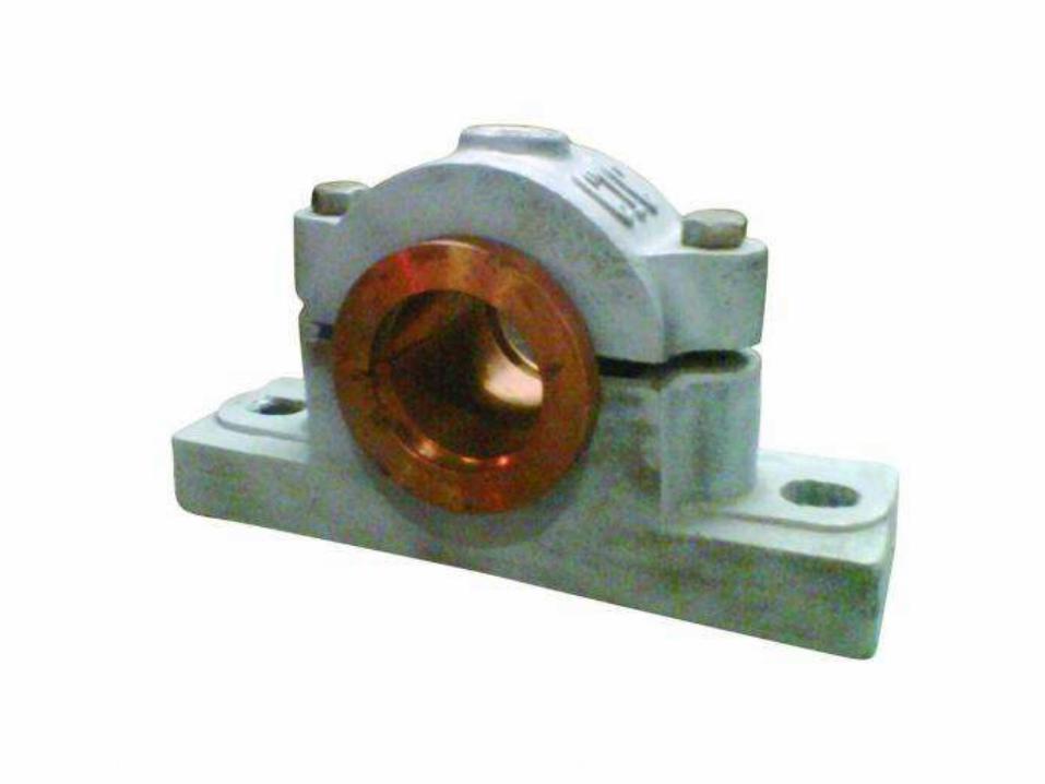
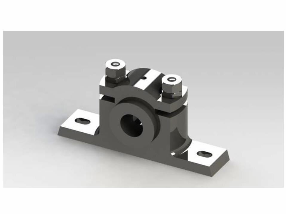
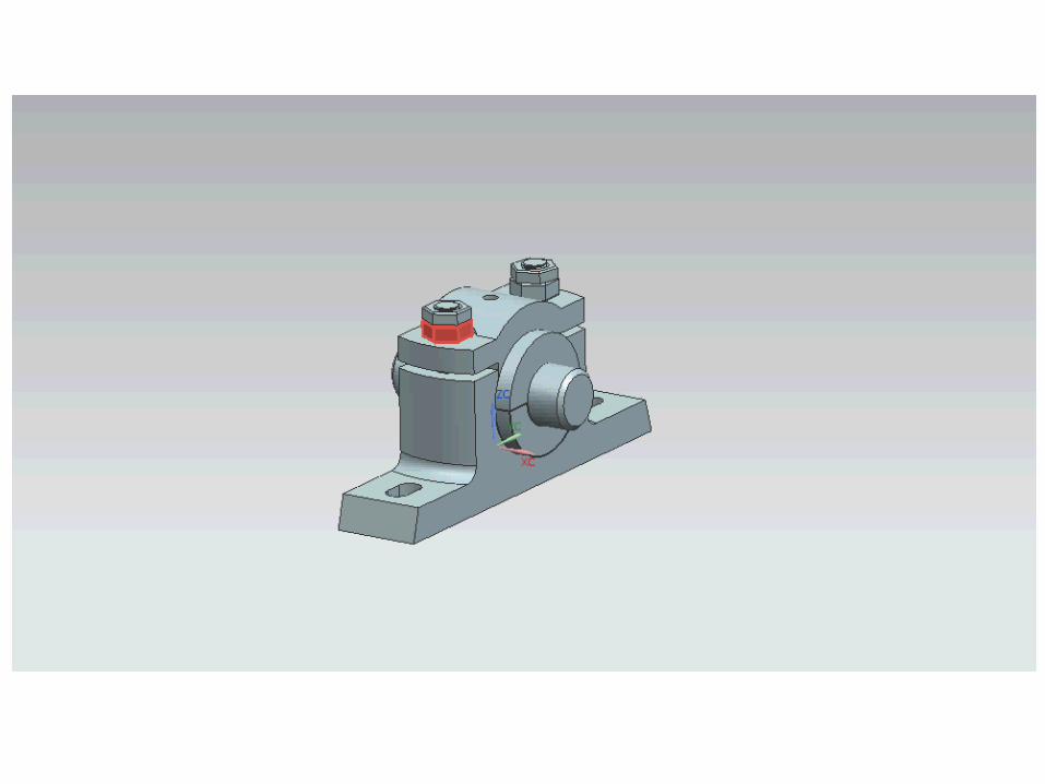
02 bearing plummer block
TRANSCRIPT

Machine Drawing- Bearing:- Plummer Block -S.GunabalanAssociate ProfessorMechanical DepartmentBharathiyar College of Engineering & TechnologyKaraikal - 609 609.Ph: 04368-265915/265916Fax : 04368-266016Mobile : 9788223359

Symbol of first & Third angle Projections

Symbol of first & Third angle Projections
Paper Plane

Symbol of first & Third angle Projections

Scale
Scale is the ratio of the linear dimension of an element of an object as represented in thedrawing, to the real linear dimension of the same element of the object itself.Designation SCALE 1 : 1 for full size,SCALE × : 1 for enlarged scales,SCALE 1 : × for reduced scales.The designation of the scale used on the drawing should be shown in the title block.
Lines
• Lines of different types and thicknesses are used for graphical representation of objects


Conventions for Sectioning
1. The objective of sectioning is to show the inner details of a machine component.
2. A cutting plane cuts the object and the section is viewed after the removal of cut portion.
3. Cutting planes are designated by capital letters and the direction of viewing is indicated by arrow marks.
4. The cutting plane(s) should be indicated by means of type H line

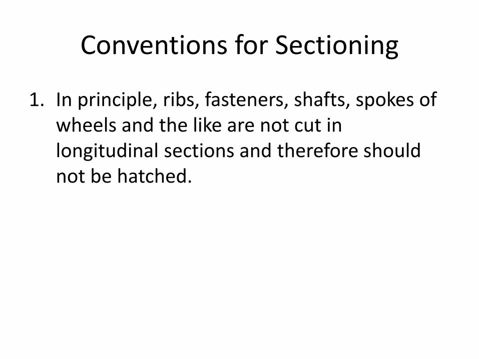
Conventions for Sectioning
1. In principle, ribs, fasteners, shafts, spokes of wheels and the like are not cut in longitudinal sections and therefore should not be hatched.

Sections not to be Hatched

Sections not to be Hatched
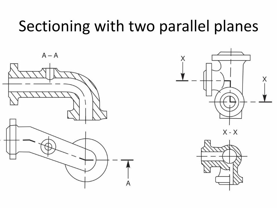
Sectioning with two parallel planes
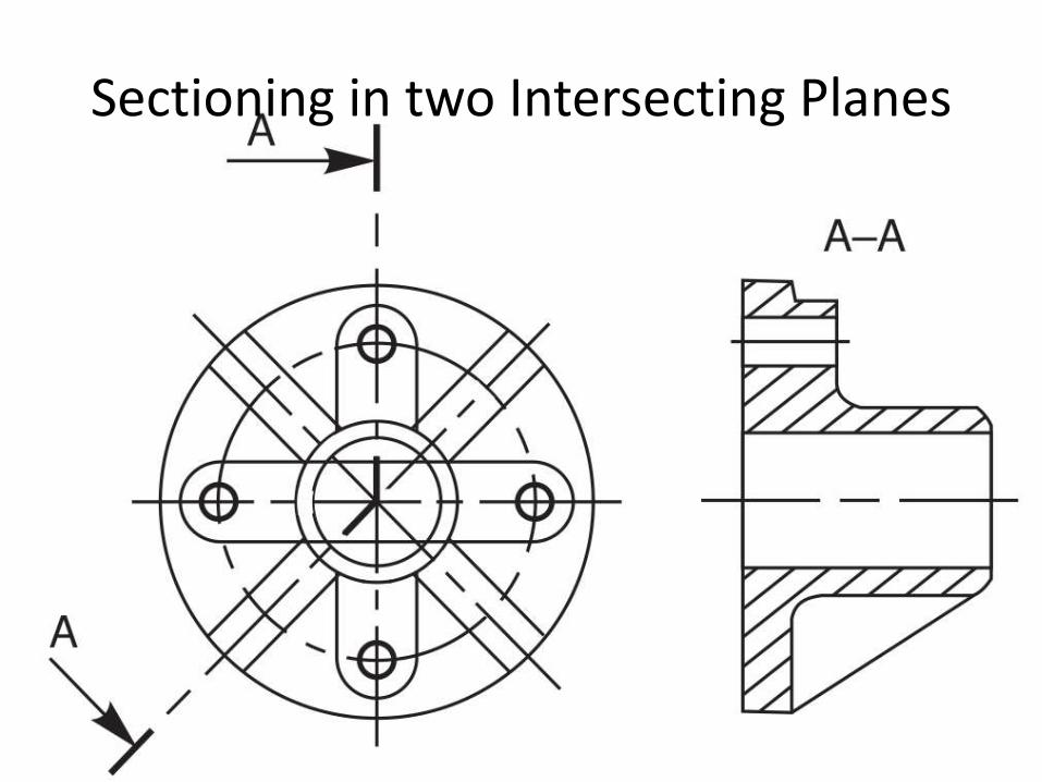
Sectioning in two Intersecting Planes


Half - Section
Symmetrical parts may be drawn, half in plain view and half in section.

A local section may be drawn if half or full section is not convenient. The local break may be shown by a continuous thin free hand line.

Successive sections may be placed separately, with designations for both cutting planes and sections


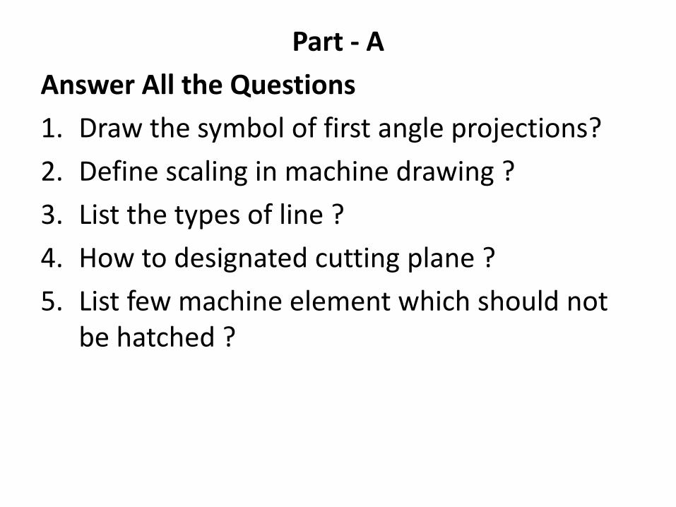
Part - A
Answer All the Questions
1. Draw the symbol of first angle projections?
2. Define scaling in machine drawing ?
3. List the types of line ?
4. How to designated cutting plane ?
5. List few machine element which should not be hatched ?
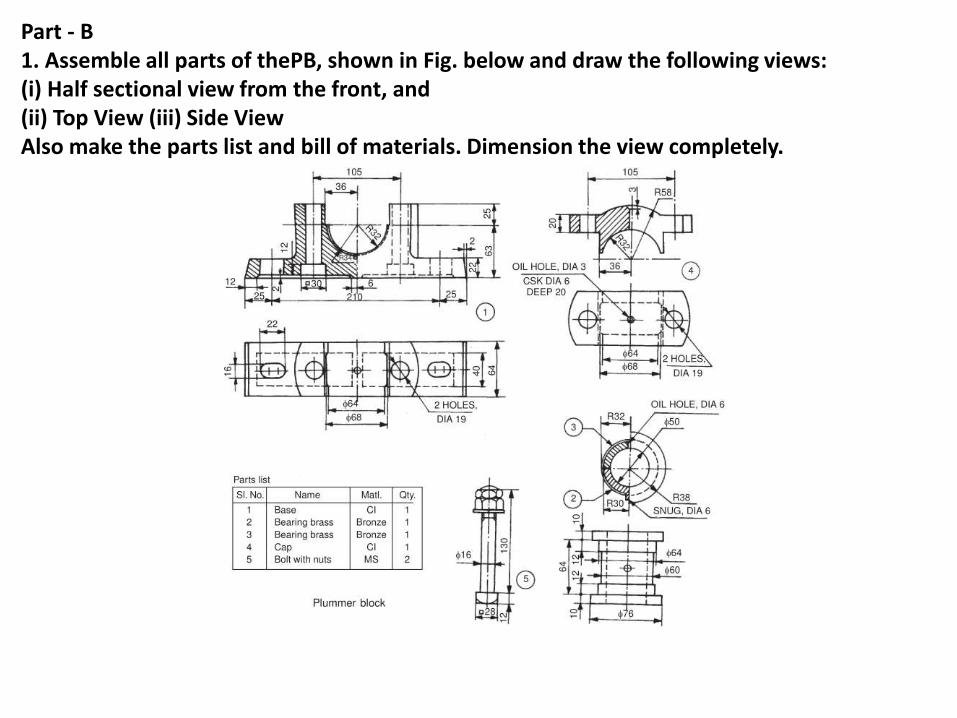
Part - B1. Assemble all parts of thePB, shown in Fig. below and draw the following views:(i) Half sectional view from the front, and(ii) Top View (iii) Side ViewAlso make the parts list and bill of materials. Dimension the view completely.