01w484 libretto unico inglese. en - tlc- · pdf filerent standards. connection with rigid pipe...
TRANSCRIPT
- 1 -
INSTRUCTION HANDBOOK
ENGLISH
ENGLAND / IRELAND
code 01W484

- 2 -
Fig. 1
Fig. 2
Fig. 4
Fig. 3
Fig. 5 Fig. 6
Fig. 7
Fig. 8
Fig. 10
Fig. 11
Fig. 9
- 3 -
Fig. 12
Fig. 13
Fig. 14
Fig. 15
Fig. 16
Fig. 17
Fig. 18
Fig. 19
Fig. 20
Fig. 21
Fig. 22
Fig. 23
Fig. 24
Fig. 25
Fig. 26

- 4 -
Fig. 27
Fig. 28
Fig. 30
Fig. 31
Fig. 29

- 5 -
IMPORTANT CAREFULLY READ THE INSTRUCTIONS CONTAINED IN THIS HANDBOOK AS THEY PROVIDE IMPORTANT INFORMATION CONCERNING SAFETY, USE AND MAINTENANCE OF THE APPLIANCE. This instruction handbook is provided for various cooker models. There may be descriptions of functions or parts that do not refer to the appliance in use. This appliance is designed and built for domestic use. Any other use is to be considered improper and therefore dangerous. The appli-ance must not be used by children or unqualified persons without supervision. DO NOT USE THE APPLIANCE TO HEAT THE ROOM. The manufacturer declines any liability for damage due to improper or incorrect use. IN CASE OF A FAULT AND/OR MALFUNCTIONING OF THE APPLIANCE, CLOSE THE MAIN GAS COCK, DISCONNECT IT FROM THE POWER SUPPLY, DO NOT TAMPER WITH IT, AND IMMEDIATELY CONTACT THE LOCAL AUTHORISED ASSISTANCE CENTRE (SEE THE ATTACHED INDICATIONS). THIS APPLIANCE COMPLIES WITH THE FOLLOWING EC DIRECTIVES AND REGULATIONS: 73/23/EEC 93/68/EEC (Low Voltage); 89/336/EEC (Electromagnetic Compatibility); 90/336/EEC (Gas); 2002/40/EC (Energy consump-tion of electric ovens); 2002/96/EC (EEEW),1935/2004/EC (Materials in contact with food). The manufacturer declines any liability in case of non-compliance with what is specified in this information handbook. The manufacturer reserves the right to modify the technical characteristics of the products, in any case respecting their safety and func-tionality. INSTRUCTIONS AND NOTES ON SAFETY Installation must be carried out by qualified personnel. It is advisable to close the main gas cock after doing any cooking. DOMESTIC SAFETY. During cooker use, the burners and electric hot-plates of the top, oven and grill become very hot. Do not allow children to stand or play in the immediate vicinity. GLASS LID (fig. 1). Do not close the glass lid when the burners or electric hot-plates are on or still hot. Always wait until they are cold. The cooker lid must be kept open when using the oven or grill. USING THE OVEN FOR THE FIRST TIME. Operate the oven and grill empty for at least 30 minutes in order to eliminate any grease or impurities deriving from the production cycle. Air the room at the same time. REMOVING PROTECTIVE FILM. Some parts of the cooker are protected with a special film. Before using the appliance remove the film, then any sticky residues with soapy warm water. POSITIONING OF BURNERS (fig. 2). There are several reference pins on the flame spreader. After removal for the cleaning phases, make sure to refit every component correctly in order to avoid malfunctioning or damage. Close the main gas cock and disconnect the appliance from the power supply before carrying out any cleaning or maintenance.
TECHNICAL INSTRUCTIONS FOR THE INSTALLER All installation, adjustment and technical maintenance operations must only be carried out by qualified personnel. The appliance must be installed in compliance with current regulations. The appliance is tested and arranged to operate on the type of gas specified on the dataplate. Before installation, make sure the local supply conditions (gas type and pressure) are compatible with those for which the appliance is arranged. The manufacturer declines any liability for direct or indirect damage caused by non-compliance with the above-mentioned instructions. This appliance is not con-nected to a fume exhaust device. It must be installed and connected in conformity with the current installation rules. ROOM VENTILATION (fig. 3). This appliance can only be installed and operate in permanently ventilated rooms as required by current regulations. The room where the appliance is installed must ensure an adequate air inflow for regular combustion of the gas. In particu-lar, the inflow of air necessary for correct combustion must not be less than 2 m3/h for every kW of appliance rated power. (See the dataplate on the appliance). The air must be drawn directly from the outside, through permanent openings or ventilation ducts that ac-cess pollution-free areas. ROOM AIRING (fig. 4). The appliance must exhaust the fumes into the outside air by means of a special hood connected to a chim-ney, flue or directly to the outside. If a hood cannot be installed it is possible to use an electric exhaust fan fitted on a window or wall facing the outside, to be started at the same time as the appliance. POSITIONING OF APPLIANCE (fig. 5). The appliance is class 1 and class 2/1. It can stand alone or be placed between cabinets, re-specting these minimum distances: 630 mm between the appliance top and overlying horizontal surfaces; 30 mm between the sides of the appliance and cabinets that are higher than it. If it is installed between cabinets the sides of the cabinets must be able to withstand an overtemperature of at least 65°C. GAS CONNECTION CONNECTION WITH METAL FLEXIBLE TUBE (fig. 6). Connection is made with a pipe conforming to the national standard, con-nected to the threaded union of the appliance with interposing of a seal joint. Pipe length must not exceed 2 metres. CONNECTION WITH RUBBER HOSE. This type of connection is not allowed when the appliance is recess mounted and the entire length of the hose cannot be inspected. The rubber hose must incorporate a bayonet connector with auto-seal in conformity with cur-rent standards. CONNECTION WITH RIGID PIPE (fig. 8). Connection must be made preferably with a copper pipe. Connect the rigid part to the threaded union located on the back of the appliance, interposing a seal joint conforming to current standards. Check connection tight-ness with a foamy solution.

- 6 -
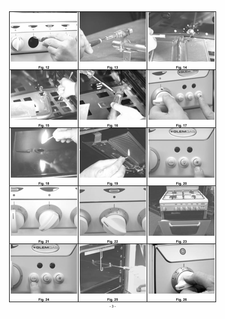
IMPORTANT After installation, make sure the unions are securely fixed. It is advisable to use a foamy solution, and never a flame, for the tightness check on gas circuits. ELECTRICAL CONNECTION. The outlet or installation must be provided with an efficient earth connection. The plug must have a 13 amp fuse (fig. 7). The yellow/green wire of the power cable must not be interrupted by switches. At the time of installation, if the con-nection is not made with a plug located in an easily reached position, install an omnipolar circuit breaker with minimum contact opening distance of 3 mm, adequate for the load and conforming to current standards, between the appliance and the mains. No part of the power cable must reach a temperature above 50°C. The manufacturer declines any liability whenever the current electrical standards are not respected and connection is not carried out in a “workmanlike way” by qualified personnel. POWER CABLE REPLACEMENT. Disconnect the appliance from the power outlet. Remove the cooker back to access the terminal block (fig. 9). Loosen the cable clamp fixing screws and the screws on the terminal block securing the three cable wires (fig. 10). Re-place the cable with an HO5 RR-F type with section adequate for the appliance’s power input, connecting it to the terminal block as fol-lows: - blue neutral wire to terminal N; - brown phase wire to terminal L; - yellow/green earth wire to terminal Fix the cable in the special cable clamp and refit the cooker back. ADAPTATION TO DIFFERENT TYPES OF GAS The appliance is suitable for working on different types of gas; each gas requires specific injectors and adjustments. To make possible variations, always disconnect the appliance from the power supply and temporarily close the mains gas supply. REPLACING COOKTOP BURNER INJECTORS (fig. 11). Manually remove the burners (no other disassembly operation is necessary) and using a suitable spanner unscrew the injectors and replace them with ones suitable for the type of gas, listed in the technical data table. MINIMUM FLAME ADJUSTMENT (fig. 12). Light the burner and leave it on at max. for about 10 minutes. Turn the knob to Min. Re-move the knob by pulling it off the cock stem. Using a small screwdriver adjust the minimum by turning the by-pass screw clockwise to decrease the flame or anticlockwise to increase it. In standard cocks the adjustment screw (by-pass) is located inside the stem (fig. 13). In valve cocks the adjustment screw (by-pass) is located on the body of the cock. After any injector replacement or adjustment op-eration always make sure the flame has a colour tending to blue, is stable and silent, does not “float” and does not cause return when going from max. to min. REPLACING OVEN COMPARTMENT BURNER INJECTORS (figs. 14/15). Remove the burners, freeing them from the fixing screws, then using a suitable spanner unscrew the injectors and replace them with ones suitable for the type of gas, listed in the technical data table. OVEN COMPARTMENT BURNER PRIMARY AIR ADJUSTMENT (MODELS WITH TUBE BURNER ONLY) (fig. 16). Loosen the rela-tive screw and, operating on the metal collar located at the end of the burner, adjust the air opening (increasing or decreasing the quantity of air) as required. After any adjustment operation always make sure the flame has a colour tending to blue, is stable and si-lent, does not “float” and does not cause return when going from Max. to Min. OVEN BURNER MINIMUM FLAME ADJUSTMENT (fig. 12). Light the burner and turn the knob to max. temperature. Allow the oven to heat for at least 10 minutes. Turn the knob to Min. Pull the knob off the thermostat stem and using a small screwdriver adjust the minimum by turning the by-pass screw clockwise to decrease the flame or anticlockwise to increase it. The flame must be short and stable, withstand possible air currents and oven door closing and must not cause return. The adjustment screw (by-pass) is normally located on the thermostat body. After any appliance component replacement or adjustment operation always carefully refit all the relative parts to restore the original functions. Adaptation must be completed by replacing the hose union. In this case also check circuit tightness with a foamy solution and never with a naked flame. Lastly, replace the old setting label with a new one (supplied) corresponding to the new gas used.
- 7 -
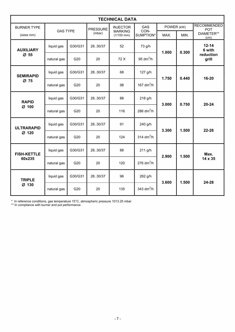
TECHNICAL DATA
POWER (kW) BURNER TYPE
(sizes mm) GAS TYPE PRESSURE
(mbar)
INJECTOR MARKING (1/100 mm)
GAS CON-
SUMPTION* MAX. MIN.
RECOMMENDEDPOT
DIAMETER** (cm)
liquid gas G30/G31 28..30/37 52 73 g/h AUXILIARY
∅ ∅ ∅ ∅ 55 natural gas G20 20 72 X 95 dm3/h
1.000 0.300 12-14 6 with
reduction grill
liquid gas G30/G31 28..30/37 68 127 g/h SEMIRAPID
∅ ∅ ∅ ∅ 75 natural gas G20 20 98 167 dm3/h
1.750 0.440 16-20
liquid gas G30/G31 28..30/37 88 218 g/h RAPID ∅ ∅ ∅ ∅ 100
natural gas G20 20 116 286 dm3/h
3.000 0.750 20-24
liquid gas G30/G31 28..30/37 91 240 g/h ULTRARAPID
∅ ∅ ∅ ∅ 120 natural gas G20 20 124 314 dm3/h
3.300 1.500 22-26
liquid gas G30/G31 28..30/37 88 211 g/h FISH-KETTLE
60x235 natural gas G20 20 120 276 dm3/h
2.900 1.500 Max. 14 x 35
liquid gas G30/G31 28..30/37 96 262 g/h TRIPLE ∅ ∅ ∅ ∅ 130
natural gas G20 20 135 343 dm3/h
3.600 1.500 24-28
* In reference conditions, gas temperature 15°C, atmospheric pressure 1013.25 mbar ** In compliance with burner and pot performance

- 8 -
POWER (kW) BURNER TYPE GAS TYPE PRESSURE
(mbar)
INJECTOR MARKING (1/100 mm)
GAS CON-
SUMPTION* MAX. MIN.
liquid gas G30/G31 28..30/37 62 145 g/h OVEN (dm3 37)
FP 96-16 2 ovens (small oven) natural gas G20 20 108 190 dm3/h
2.000 0.700
liquid gas G30/G31 28..30/37 79 193 g/h OVEN
(dm3 47/67) 55-65-75-66
P85-P96 FG 96-16 2 ovens
(medium-size oven) natural gas G20 20 122 252 dm3/h
2.650 1.000
liquid gas G30/G31 28..30/37 93 276 g/h OVEN (dm3 80/105)
85-86 (large oven) natural gas G20 20 140 362 dm3/h 3.800 1.000
liquid gas G30/G31 28..30/37 98 305 g/h OVEN (dm3 111/123)
96-16 (giant oven) natural gas G20 20 150 400 dm3/h 4.200 1.000
liquid gas G30/G31 28..30/37 60 116 g/h GRILL (dm3 37)
FP 96-16 2 ovens (small oven) natural gas G20 20 101 152 dm3/h
1.600
liquid gas G30/G31 28..30/37 65 145 g/h GRILL
(dm3 47/67) 55-65-75-66
P85-P96 FG 96-16 2 ovens
(medium-size oven) natural gas G20 20 108 190 dm3/h
2.000
liquid gas G30/G31 28..30/37 88 240 g/h GRILL (dm3 80/123) 85-86-96-16
(large oven and giant oven) natural gas G20 20 136 314 dm3/h
3.300
* In reference conditions, gas temperature 15°C, atmospheric pressure 1013.25 mbar

- 9 -
TABLE OF ELECTRIC POWERS (MIXED, ELECTRIC, MULTIFUNCTION OVENS)
TYPE OF COOKER AND OVEN
P85 55, 65, 75, P85 56, 66, 76, P96 85, 86, 96, 16 96, 16 (2 OVENS)
small oven
medium-size oven
medium-size oven
large oven giant oven
small oven
medium-size oven
47 dm3 51/58 dm3 61/67 dm3 80/123 dm3 37 dm3 61/67 dm3
FUNCTION
W W W W W W
OVEN LIGHT
15 15 15 15 15 15
ELECTRIC GRILL
1350 1350 1400 1500/2000 1200 1400
ROOF FLOOR
600 900
650 1100
850 1400
950 1500
500 800
700 1100
ROOF
600 650 850 950 500 700
FLOOR
900 1100 1400 1500 800 1100
FAN
30 30 30 30
ROUND + FAN
2200 30
2200 30
2400 30 2200
30
GRILL + FAN
1350 30
1400 30
1500/2000 30 1400
30
ROOF FLOOR FAN
650 30
1100
850 30
1400
950 30
1500
700 30
1100
DOUBLE GRILL
650+1350 850+1400 950+1500 700+1400
DOUBLE GRILL + FAN
650+1350 30
850+1400 30
950+1500 30 700+1400
30
FLOOR + FAN
30 1100
30 1400
30 1500 30
1100

- 10 -
TABLE OF ELECTRIC POWERS (MIXED, ELECTRIC, VITROCERAMIC TOPS)
TYPE OF ELECTRIC HOT-PLATES DIAMETER cm
POWER W
A1 Electric hot-plate 18 1500
A2 Electric hot-plate 18 2000
C Electric hot-plate 14.5 1000
D HL round hot-plate 14.5 1200
E HL round hot-plate 18 1800
F HL round hot-plate 21 2200
G HL extensible hot-plate 17/26.5 1400/2200
H HL extensible hot-plate 12/21 700/2100
TYPE of TOP PRESENCE OF ELECTRIC HOT-PLATES
16/35 A1 17/30/21 A1 C 09 A1 A2 C C 14/29 C 10 D D E F 23 D D G H 24 D D F G H

- 11 -
OVEN TYPES AND FUNCTIONS
(G) GAS OVEN
0
0…250 OFF OVEN
burner GRILL
burner
(M) MIXED OVEN
0
0…250 OFF OVEN
burner electric
GRILL
(Q) MIXED OVEN WITH FAN
0
0…250 OFF OVEN
burner fan
electric GRILL
(E) ELECTRIC OVEN
0
0…250 OFF OVEN LIGHT ROOF
FLOOR ROOF FLOOR GRILL
(X) MULTIFUNCTION OVEN - 3 POSITIONS
0
0…250 OFF FAN ROUND
+ FAN GRILL +
FAN
(W) MULTIFUNCTION OVEN - 6 POSITIONS
0
0…250 0…250 OFF OVEN
LIGHT ROOF
FLOOR FLOOR ROOF
FLOOR FANFLOOR
WITH FAN DOUBLE GRILL +
FAN
(V) MULTIFUNCTION OVEN - 8 POSITIONS 0
0…250 0…250 OFF OVEN
LIGHT FAN ROOF
FLOOR ROUND + FAN
GRILL DOUBLE GRILL
DOUBLE GRILL +
FAN
FLOOR WITH FAN

- 12 -
USER INSTRUCTIONS LIGHTING COOKTOP BURNERS (fig. 17). Bring a match (a spark generator or flame) to the burner, press and turn the corresponding knob anticlockwise to MAX. setting. (In some models the burner incorporates an electric igniter device activated by a separate pushbut-ton or by pressing the knob). If the burner does not light within 15 seconds wait at least 1 minute before repeating the operation. For models equipped with safety thermocouple, after lighting keep the knob pressed for about 10 seconds. Then adjust the flame level ac-cording to needs, making sure to position the knob in the zone between max. and min. and never between max. and zero. LIGHTING OVEN COMPARTMENT BURNERS (fig. 18/19). Lighting of the burners located inside the oven must always occur with the oven door completely open. Press and turn the corresponding knob anticlockwise to MAX. setting. Bring a match to the hole located on the oven base (to light the grill burner bring the match to the front end holes). In some models the burner has electric ignition activated by a separate pushbutton (fig. 20) or by pressing the knob. After lighting keep the knob pressed for about 15 seconds. IMPORTANT: if the burner does not light within 15 seconds wait at least 1 minute before repeating the operation. OVEN PREHEATING. After lighting the burner wait a few minutes then close the door and adjust the knob to the required temperature. Preheat the oven empty for at least 15 minutes before introducing food for cooking. TURNING ON AND USE OF ELECTRIC HOT-PLATES (fig. 21). The electric hot-plates are switched on by turning the corresponding knob from 0 to the required setting. The various power options are indicated by numbers (0, 1, 2, 3…). The electrical power used in-creases according to the numbers. When turning on a hot-plate for the first time or after a long period of disuse it is advisable to oper-ate it empty at “min. heat” setting for at least 15 minutes in order to eliminate any moisture absorbed by the insulation. To optimise use of the electric hot-plates use flat-bottomed pots and avoid using pots of smaller diameter than the hot-plate. TURNING ON AND USE OF ELECTRIC OVENS (fig. 22). The electric ovens are generally controlled by a function selector combined with a thermostat for choosing the required temperature. Different options are available for setting different types of cooking, depending on the oven model. For immediate access to the cooking functions in ovens equipped with programmer (manual, analogue or elec-tronic), always make sure to set the control to “manual”. See the instructions and operating advice for optimising the basic requisites essential for obtaining perfect cooking: preheating, function, temperature, insertion level, time. GRILL (fig. 23). The grill (gas burner or electric heating element) must be used in the conditions specified for the cooker model used. In some models grilling must be carried out with the oven door ajar. In these cases it is necessary to apply a mechanical knob protec-tion device normally supplied with the cooker. Caution: the accessible parts can be very hot when the grill is used. Keep children away. USING THE SPIT (fig. 24). Depending on the different oven types, the spit can be activated by a manual pushbutton or automatically at the same time as grill heating element operation. Place the food to be cooked on the spit rod making sure to push it between the two forks and balance the weight in the middle to avoid pointless forcing of the spit motor during turning. Place a pan containing a few dl of water in the step below to limit spatters of fat and excess smoke during cooking (fig. 25). TIMER, CLOCK, PROGRAMMERS (MECHANICAL, ANALOGUE, ELECTRONIC). The mechanical timer is activated by turning the knob all the way clockwise to load the mechanism, then anticlockwise to set the required time (fig. 26). The time is given in minutes; a ringer signals the end of the set time. In some cooker models, in addition to acoustic signalling the clock also acts as a switch turning off the electrical connection to the oven functions. For immediate use of the oven without setting the cooking time, turn the clock knob to “manual” (fig. 27). On models provided with programmer it is possible to program switch-on, duration and switch-off of some electric oven functions. In this case also, use of the oven without settings occurs by previously setting the “manual” function (fig. 28). COOLING FAN. Some cooker models have a cooling device that operates during oven use. On some models this device operates automatically and no additional operation is required by the user. In some models the cooling fan continues to work even after the oven functions are switched off and stops automatically, commanded by a residual temperature control sensor. In any case, cooling fan op-eration does not alter or modify gas or electric cooking and failed fan operation does not affect the safety of the appliance or the user. This “courtesy” device shortens normal cooker component cooling times. COOKING SUGGESTIONS In the phases prior to cooking make sure only indispensable accessories are inside the oven (normally just the grill on which the con-tainer with food to be cooked will be placed after preheating). It is a good rule to always preheat the oven for at least 15 minutes before introducing the food. For best cooking results it is essential to choose a suitable function, temperature, insertion level and time for each type of dish: - different functions are available depending on the type of oven. - the temperature is set by using the specific variable thermostat control. - there are normally 4 insertion levels (1 lower, 2 middle, 1 upper) (fig. 29). - cooking times usually depend on the dish type and quantity, different eating habits, taste and personal experience. The indications given for the recipes are generally sufficient for obtaining satisfactory cooking results. The middle insertion levels are normally suitable for most cooking because it is in this part of the oven that, with thermostat setting, per-fect stabilisation of the set temperature occurs. In gas ovens the lower the insertion level the closer the food is to the heat source (pasta, puddings, roasts). Use higher levels to move the food further away from the heat source, for rising and gentle cooking. In electric ovens the higher the level the closer to the heat source (greater browning on the surface of food and grilling). Food portions and the use of food containers of different material and thickness (earthenware, glass, aluminium, steel) can determine different cooking times from those given in the recipes. Cooking with forced ventilation produces high removal of moisture from foods and is usually recommended for cakes with whipped mix-ture, simultaneous cooking and thick portions. With gentle cooking and rising, avoid opening the door or open it only when strictly necessary, so as not to alter the thermostatic heat-ing cycles. When using the grill or spit, place a pan containing a few dl of water in the step below to limit spatters of fat and excess smoke during cooking.

- 13 -
For significant energy saving, in long cooking the residual heat can be used by turning the oven off a few minutes before the average times given in the recipes, and keeping the door closed. The oven compartment’s perfect insulation will ensure perfect cooking of the dish. OVEN FUNCTIONS SPECIFIC COOKING CHARACTERISTICS OVEN burner
The heat comes from below. Suitable for any type of dish. For gentle cooking and rising, use higher insertion levels with respect to the burner and always ensure adequate preheating times.
GRILL burner
Direct exposure of food to the heating power of the flame. Suitable for any type of food for quick and intense grilling. Useful for final browning of pasta and puddings.
OVEN burner with fan
The heat comes from below and the fan spreads it evenly, attenuating the impact of the powerful burner on foods. Suitable for any type of dish. Always preheat the oven.
electric GRILL
Direct exposure of food to the heat of the electrical heating element. Used for removing the fat from particular types of meat, it adapts perfectly to the characteristics of dietetic cooking.
ROOF FLOOR
Traditional electric cooking. The heat produced by the two heating elements envelops the food and optimises the cooking of any kind of dish. Use middle insertion levels for cakes and pastries.
ROOF
Minimum power used. Ideal for heating smaller portions of food.
FLOOR
The heat coming from below optimises slow and low temperature cooking. Reduced energy con-sumption, ideal for warming precooked foods.
FAN
Favours thawing of foods, reducing the times normally taken by about 1/3.
ROUND + FAN
Ventilated cooking. The heat is spread evenly at all insertion levels. Respecting the different times allows multiple cooking of different dishes. The high removal of moisture optimises the cooking of vegetables, fish and cakes with whipped mixture.
GRILL + FAN
The fan together with the heating element favours heat circulation for gentler cooking. Ideal for thorough cooking of particularly large portions of meat.
ROOF FLOOR FAN
Traditional electric cooking combines with ventilation useful for spreading the heat evenly, high removal of moisture and an even temperature at the various levels. Suitable for any type of cook-ing.
DOUBLE GRILL
Ideal for grilling on a large area.
DOUBLE GRILL + FAN
The fan together with the powerful action of the heating elements reduces cooking times for large portions of food.
FLOOR + FAN
The heat from below is evenly spread in the oven and allows slow and gentle cooking with low waste of energy.

- 14 -
MAINTENANCE Before carrying out any maintenance or cleaning, close the main gas cock and disconnect the appliance from the power sup-ply. GREASING THE COCKS. If the movement of a cock or thermostat eventually becomes difficult, greasing can be carried out. This op-eration must only be performed by authorised personnel. OVEN LAMP REPLACEMENT (fig. 30). Disconnect the appliance from the power supply. Unscrew the protection cover protruding in-side the oven. Unscrew and replace the lamp with one of the same power and resistant to high temperatures (300°C). Refit the cover. OVEN DOOR REMOVAL (fig. 31). Open the oven door. Block the two hinges in the open position using the movable hooks. Lift the door and pull it outwards to unhook it from the fixed hinges of the cooker. To refit, carry out the same steps in reverse order. CLEANING Efficient periodical cleaning is necessary for avoiding deposits of fat that can eventually produce fumes, unpleasant smells and operat-ing anomalies. Grills, burners, knobs, pans and glass can be removed for careful cleaning which must be done with lukewarm soapy water or specific products normally available on the market. Do not use steel wool, powder detergents, soda-based surface actives, abrasive pads, or products containing acids or chlorine. All the washed parts must be rinsed and thoroughly dried before being used. Every removed or disassembled part must be carefully put back in its original place for correct and safe operation. MAINTENANCE AND CLEANING OF STAINLESS-STEEL (AISI 304, AISI 430) SURFACES. To remove food stains and hardened deposits use warm soapy water and also a wooden spatula if necessary. In case of lines or scratches, the surface can be smoothed using very fine steel wool or abrasive felts in fibrous synthetic material, making sure to rub in the direction of original satin finish. To remove rust stains due to inadequate maintenance or contact with oxidants, use specific products by consulting producers of deter-gents for industrial use (e.g. Soilax, Diversey, Level, Oakite, Henkel). To remove any discolouring caused by burns or marks caused by heat, use specific products available on the market (e.g. Smac brillacciaio) which, in addition to restoring the steel’s natural brightness, act as protection by preventing the penetration of moisture and dirt that cause corrosion. CLEANING GLASS AND CHROMED SURFACES: always clean the glass when the door is cold using a moist cloth and specific de-tergents for glass (e.g. Vetril, Deco, Glassex). DISPOSAL (fig. 31) This electrical appliance has components classified as EEEW (electrical and electronic equipment waste) requiring selective treatment for correct ecological disposal. EEEW includes: condensers, switches, printed circuits, electrical cables. THIS ELECTRICAL APPLIANCE MUST NOT BE DISPOSED OF IN MIXED URBAN WASTE BUT MUST BE SENT TO SEPARATE COLLECTION:
Fig. 31
The purposes of Directive 2002/96/EC for differentiated treatment of EEEW are, in particular: protecting, safeguarding and improving the environment, the protection of human health and the expedient and rational use of natural resources. When a new appliance is supplied, the distributor undertakes to collect this electrical appliance and have it sent to authorised treatment centres for the disposal of EEEW. The producer of this electrical appliance meets the requirements of Directive 2002/96/EC by promoting and supporting the recovery, reuse and recycling of EEEW. ELECTRONIC PROGRAMMER GENERAL INSTRUCTIONS ON OPERATION. After pressing a function button the required time can be set with the +/- buttons. Ad-justment is quicker by keeping the required button pressed. By lightly pressing and releasing the function button the selected function is displayed for 5 seconds, during which it is possible to carry out setting. The display returns to the exact time 5 seconds after releasing a function button or completing a setting. A set program starts immediately. Complete the programming by selecting the required func-tion and oven temperature with the relative commands. Three flashing 0’s appear on the display immediately after electrical connection (and after a possible power failure). Set the exact time. SETTING THE EXACT TIME (CLOCK). Select the clock function by pressing the Cooking time and End of cooking time buttons simul-taneously. Set the clock with the +/- buttons. MANUAL OPERATION. Press the Cooking time and End of cooking time buttons simultaneously. The A symbol (automatic program) is cancelled and the pot symbol (manual function) lights up. With this operation any set program is cancelled. SEMIAUTOMATIC OPERATION: COOKING TIME. Press the Cooking time button and set the duration with the +/- buttons. The A symbol (automatic program) and the pot symbol appear. The relay output is activated. At the end of cooking the acoustic signal sounds, the relay is deactivated and the A symbol flashes.
- 15 -
SEMIAUTOMATIC OPERATION: END OF COOKING TIME. Press the End of cooking time button and set the required time with the +/- buttons. The A symbol (automatic program) and the pot symbol appear. The relay output is activated. At the end of cooking the acoustic signal sounds, the relay is deactivated and the A symbol flashes. AUTOMATIC OPERATION: DURATION, COOKING END AND START TIME. Press the Cooking time button and set the duration with the +/- buttons. The A symbol (automatic program) and the pot symbol appear. The relay output is activated. Then press the End of cooking time button and set the required time with the +/- buttons. In this way a delayed start of cooking time can be determined. If the setting is not correct an acoustic signal warns of the programming anomaly. At the end of cooking the acoustic signal sounds, the relay deactivates and the A symbol flashes. TIMER (CONTROL OF MINUTES WITH SUBSEQUENT ACOUSTIC SIGNAL). Press the Timer button and set the required time with the button and the +/- buttons. The bell symbol is lit while the set time passes. The acoustic signal sounds at the end of the set time. ACOUSTIC SIGNAL. The acoustic signal sounds for 7 minutes at the end of the control cycle or the cooking program. Press any one of the three function buttons (Timer, Cooking time and End of cooking time) to switch off the signal. Press the button (-) to personalise the acoustic signal tone. PROGRAMMING CHECK AND SETTING ERRORS. Any programming in progress can be checked by pressing the specific function button. Any programming error is signalled by the acoustic signal and intermittence of the A symbol. CANCELLING A PROGRAM. A program can be cancelled by selecting the manual function (press the Cooking time and End of cook-ing time buttons simultaneously). ELECTRONIC TIMER SETTING THE EXACT TIME (CLOCK). Press BUTTON 1 and release. Press BUTTON 3 for the numerical progression (+) and BUTTON 2 for the return (-). After setting the EXACT TIME wait 10 seconds for automatic storing of the operation. TIMER SETTING. Press BUTTON 3 for the numerical progression (+); press BUTTON 2 for the return (-). Times from a minimum of 10 seconds to a maximum of 10 hours can be set. The countdown will be displayed after about 5 seconds, after which the acoustic signal sounds. STOPPING ACOUSTIC SIGNAL. Press BUTTON 3.

- 16 -