015-jh-1903
TRANSCRIPT
7/25/2019 015-JH-1903
http://slidepdf.com/reader/full/015-jh-1903 1/163
þ
*
ú
)+
Clíent
E
pÀtron
\Þñi
Bv/
evision
rÆít:::-tlÞì
ate
ev
-.-:-
ssuED
FoR
tNV|TATTON
Tg¡lR_
MAR
93
ISSUED
AS
KOC
ENG
GROUP
SPEC
5
SEP
94
@
(dJ.
Ê.
U¡)
.:*¿35J1
L '
ãS-;É
KUWAIT
OIL
COMPANY
(K.S.C.}
Engineering
Group
Specification
Nymher
oî
6-JH-1903
General
lnstruments
7/25/2019 015-JH-1903
http://slidepdf.com/reader/full/015-jh-1903 2/163
CONTENTS
1.O
2.O
SCOPE
STANDARD
SPECIF¡CATIONS
3.0
SEBVICE
CONDITIONS
6
6
7
7
I
3.1
ExternalConditions
3.2
Sulphide
Stress
Cracking
Considerations
. .
4.O
BASIC ENG¡NEERING
INFORMATION
4.1 Hazardous
Area
.
4.2
Explosive Hazard
Protection
Methods
4.3
Protection
from
the
Environment
4.4
Utilities
I
I
II
I
I
10
11
12
12
13
13
14
14
4.5
Measurements
and Scales
4.6
Connection Sizes and
Type
.
.
. .
lnstrument
ldentification
. .
Limitations on
Selection and Approved
Manufacturers
List
.
.
Line
Break Detection
Use
of
Barrier
Glands
Shop
lnspection
and
Testing
Painting and Protective
Finishing
Packing, Marking and
Documentation
.
.
.
.
Spare
Parts
and
Maintenance
Requirements
5.0
CONTROL
VALVES
Applicable Standards
4.7
4.8
Scope
of
Control
Valve
Selection
Valve Types
Valve Sízing Requirements
Trim
Select¡on
.
Valve
Design
Requirements
. .
Actuator
Selection
and
Sizing
11
12
13
14
6.0
RELIEF
AND
SAFETY
VALVES
6.1
Applicable
Standards
6.2
Scope
of Relíef
Valve Section
Relief
Applications
and
Selection
Sizing
Requirements
. .
Design,
Materials
and
Construction
Noise
4.9
4.10
4.11
4.12
4.13
4.14
1
2
3
4
5
b
7
I
I
10
1
5
5
5
5
5
5
5
5
5
5
5
5
5
5
16
19
21
23
26
30
32
33
35
38
43
45
46
46
46
47
50
52
55
Actualor
Construction
Noise,
Flashing
and
Cavitation
Construction
Requirements
lnstallation
Notes,
Bypass
and Handwheel Philosophy
.
.
Accessories
and
Ancillary
ltems
.
.
Performance
Req
uirements
Nameplate
Data
.
.
6.3
6.4
6.5
6.6
Sheet
2 of
163
Data
15-9-94
Rev
pecificarion
Number
01s-JH-1903
@l0l';{*,w:-*
cû
N1
2-0056
ir
7/25/2019 015-JH-1903
http://slidepdf.com/reader/full/015-jh-1903 3/163
lnstallation
Notes
.
Performance
Requirements
Nameplate
Data
7.O
FLOW
MEASUREMENT
7.1
ApplicableStandards
7.2
Scope
of
Flow
Measurement
Section
7.3
Flow lnstrument
Types
and
Selection
. .
.
7.4
Sizing
and
ents
.
7.5
Constructi
7.6
lnstallation
Notes
7.7
PerformanceReguirements
7.8
NameplateData....
8.O
PRESSURE
MEI\SUREMENT
6.7
6.8
6.9
.55
.55
.57
58
58
58
58
62
64
68
71
72
8.3
Pressure
lnstruments
Type
and
Selection
8.4
Sizing
and Ranging
Requirements
8.5
Design
and
Constfuction
8.6
lnstallation
Notes .
.
. .
8.7
PerformanceRequirements
8.8
Nameplate
Data
.
9.O
TEMPERATURE
TüEASUREMENT
9.1
Applicable
Codes
9.2
Scope
of
Temperature Measurement
Section
. .
.
.
9.3
Temperature
lnstrument
Types
and
Selection
9.4
Sizing and
Ranging
Requirements
Construction
Requirements
lnstallation
Notes
.
.
Performance Fìequirements
Nameplate
Data
1O.O
LEVEL
MEASUREMENT
1O.1
Applicable
Standards
1O.2
Scope of
Level
Measurement
Section .
. .
10.3
Level
lnstrument
Type and
Sefection
10.4
Sizing and
Ranging
Requirements
.
.
10.5
Construction
Requirements
10.6
lnstallation
Notes
1O.7
Performance
Requirements
1O.B
Nameplate
Data
.
11.0
TANK
METERING
1
1.1
Applicable
Standards
9.5
9.6
9.7
9.8
8.1
8.2
11.2
11,3
11.4
Applicable
Standards
Scope
of
Pressure
Measurement
Section
. .
. .
Scope
of Tank
Metering
Section
Tank Metering
lnstruments
Type
and Selectíon
Sizing and
Ranging
Requirements
.
1
1,5
Construction
Requirements
72
72
72
73
7A
76
81
a2
83
83
83
83
83
85
86
91
91
92
93
93
93
93
97
99
106
106
108
108
108
108
109
110
112
Sheet
3
of
163
Date
1
5-9-94
Rev
pecification
Numbe¡
01s-JH-1903
@l0liJl,t:# ;x:'*'
{y
Nl
2-0056
7/25/2019 015-JH-1903
http://slidepdf.com/reader/full/015-jh-1903 4/163
lnstallation
Notes
Performance
Requ
irernents
Nameplate
Data
12.0 LOCAL
PNEUMATIC
CONTROLLERS
12.1
Scope
of
Local
Controller
Specification
12.2
Pneumatic
Controller
Types
and
Selection
.
.
12,3
Sizing
and
Ranging Requirements
12.4
Design
and
Construction
lnstallation
Notes
Performance
Requirements
Nameplate
Data
6
7
I
11
11
11
112
113
115
115
115
115
117
117
118
118
119
119
119
119
120
120
121
121
122
2.5
2.6
2.7
1
1
1
13.0
SPEED
MEASUREMENT
13.1
Scope
of
Speed
Measurement Section
13.2
Speed
Measurement
lnstruments
Type
and
Selection
13.3
Sizing and
Ranging Requirements
13.4
Construction
Requirements
13.5
lnstallation
Notes
13.6
Performance
Requirements
13.7 Nameplate
Data
14.O
VIBRATION
SENSING
14.1
Scope
of
Vibration
Sensing
Section
14.2
Vibration
Sensing
lnstruments
Type
and
Selection
14.3
Sizing
and
Ranging
Requirements
.
.
14.4
Construction Requirements
.
.
14.5
lnstallation
Notes
1
4.6
Performance
Requirements
14.7
Nameplate Data
15.0
SOLENOID
VALVES
122
122
122
123
123
123
123
124
124
124
124
125
126
126
128
128
129
15.1
15.2
15.3
Applicable
Standards
Scope
of
Solenoid
Valve Section
Solenoid
Valves
Types
and
Selection
Construction
Requirements
.
.
.
.
lnstallation
Notes
Performance
Req
uirements
Nameplate
Data
15.4
Sizing
and Ranging
Requirements
5.5
5.6
5.7
5.8
1
1
1
1
16.0
SIGNAL
CONVERTORS
16.1
Scope
of
Signal
Converter
Section
16.2
Signal Converters
Type
and
Selection
.
16.3
Sizing
Requirements
16.4
Construction
Requirements
.
. .
lnstallation
Notes
Performance
Requirements
Nameplate
Data
16.5
16.6
16.7
129
129
129
130
130
131
132
133
Sheet
4of
163
Date
15-9-94
Rsv
pecification
Number
01s-JH-1903
@l0l ;:mx^Group
(t
N12-OOs6
7/25/2019 015-JH-1903
http://slidepdf.com/reader/full/015-jh-1903 5/163
17.0
POSTT|ON
SWTTCHES
133
133
133
134
134
134
135
135
17.1
Scope
of
Position
Switches
Section
17.2
Position
Switches
Type
and Selection
17.3
System
Requirements
. .
.
17.4
Construction
Requirements
17.5
lnstallation
Notes
17.6
Performance Requirements
17.7
Nameplate
Data
.
18.O
FLAME DETECTION
135
135
135
137
137
138
138
139
18.1
Scope
of
Flame
Detection
System
18.2
Flame
Detection
Types
and Selection
18.3
System
Requirements
18.4
Construction
Requirements
18.5
lnstallat¡on
Notes
18.6 Performance
Requirements
18.7
Nameplate
Data
.
19.O
MISCELLANEOUS INSTRUMENTS
139
139
139
140
140
140
141
141
142
19.1
Applicable
Standards
. .
.
19.2
Scope
of
Miscellaneous
lnstrument
Section
19.3
Selection
t,
q
19.4
Sizing
and Ranging
Requirements
1
1
1
1
9.5
9.6
9.7
9.8
Construction
Requirements
lnstallation
Notes
. .
.
.
Performance
Requirements
NameplateData....
20.O
ANALYSERS
142
142
142
142
143
143
155
155
156
2Q.1
Applicable
Standards
2O.2
Scope
of
Analysers
Section
20.3 Analyzer
Types
and
Selection
20.4
Sizing and
Ranging
Requirements
20.5 Construction
Requirements
. .
..
20.6 lnstallation
Notes
20.7
Performance
Requirements
20.8
Nameplate
Data
21.O
LOCAL PANELS
ANT}
GAUGE
BOARDS
157
157
157
158
158
161
162
163
21.1
21.2
21.3
21.4
21.5
21.6
21.7
Scope
of
Local
Panel
and
Gauge Board
Selection
Local
Panels
and
Gauge
Boards
Type
and Selection
Sizing
Requirements
Construction
Requirements
. .
.
lnstallation
Notes
Performance
Requirements
Nameplate
Data
Sheet
5
ol 163
Dats
1
5-9-94
Rev
pacification
Number
015-JH-t
903
@l0l,Y, m,G raup
il
N12-0056
7/25/2019 015-JH-1903
http://slidepdf.com/reader/full/015-jh-1903 6/163
û
TË,1,
\\\
1.O
SCOPE
1.1
This specification
details
the
design, manufacture,
¡nspection,
testing
and
supply
of
plant
instrumentation
for
installation
at the
Facility
in Kuwait.
1,2
The
plant
instrumentation
shall
fully
comply
wíth
all
relevant
contractual
requirements
specified
in
the
Scope
of Work
and
Technical
Specification
of
the
contract.
1,3
The
provisions
of
this
specification
shall
appty to
all major
and
ancillary
plant,
proprietary
equipment
and
packaged
units
unless
otherwise
agreed
to
¡n wr¡ting
by the
company.
2.A
STANDARD
SPECIFICATIONS
2.1
lnstruments,
systems
and
equipment
shall
conform in
design,
materials
and
performance,
except
where
otherwise
specified,
wíth
the current
issue
and
amendments
of
the
applicable
codes
and
standards
prevailing
on
the
effective
date of
the Contract:
2.1.1
lnternationalStandards
NACE
MRO175
Material
Requirements
-
Sulphide
Cracking
Resistant
Material
Íor
Equipment
Stress
Oiffield
2.1.2
Brit¡sh
Standards
BS
5345
Code
of
Practice
for
the
Selection,
lnstallation
and
Maintenance
of
Electrical
Equipment
for
Use
in
Potentially
Explosive
Atmospheres
BS
5490
Specification
for
Classificatíon
of
Degrees
of
Protection
provided
by Enclosures
BS
5501
ElecÍical
Apparatus
for
Potentially
Explosive
Atmospheres
(Also
CENELEC
Std
EnEO.Ot4-
O2O
and
029)
2.1.3
Engineering
Group
Specifications
All
equipment
and
accessories
covered by
this
specificatíon
shall
comply
with
all
relevant
Engineering
Group
specifications
of
which
the
following
are
specifically
referenced
in
this
specification:
015-AH-10O1
Basic
Design
Criteria
01
5-AH-1002
lnternational
Codes
Shoet
6of
163
Oate
15-9-94
Hev
pecificatíon
Number
01s-JH-1903
@KÏlTJn:iJx,Group
L/
fr
Nl
2-0056
7/25/2019 015-JH-1903
http://slidepdf.com/reader/full/015-jh-1903 7/163
t',
J>
*-
ú
3.0
015-JH-1901
lnstrumentEngineeringBasicData
01
5-JH-1902
lnstrumenr
Design
015-JH-1905
Emergency
Shutdown
panel
015-JH-1907
Motor-OperatedVatves
015-JH-19O8
lnstrumentlnstallation
O1s-JH-1909
lnstrumentationforpackageEquipment
01s-KH-1902
spare
parts
and
Maintenance
Requirements
O15-NH-1
104
Plant/Equipment
Noise
Control
01s-PH-1901
Erectrical
Design,
rnstailation
and
resting
O1s-XH-1005
Shop
and Field
painting
015-UH-10O1
packing,MarkingandDocumentation
2.2
A
non-inclusive
listing
of applicable
codes
and
standards
shall
be
found
in
the
Engineering
Group
Specification
ent¡tled lnstrument
Engineering
Basic
Data
{Number
01
5-JH-1
901
}.
2.g
Specifically
applicable
codes are
found
at
the
beginning
of
each
section
of
this specification.
2.4 Compliance
with
this
specification
shall
not
relieve
the
Contractor
of
its
responsibility
to
supply
equipment
suited
to
meet
the specified
service
conditions
and
applicable
regulatÍons.
2.5 Where
conflícts
exist
between
this
specificatíon
and
other
Ðrawings,
standards,
codes and
specifications.
the
most
stringent
shall
be
applied.
SERVICE
CONDITIONS
3.1
ExternalConditions
3.1 .1 The
equipment
shall
be
suitable
for continuous
operation
at
a
desert locatÍon
under
high
ambient
temperatures
and
humidity.
The
atmosphere
at
the
Facility
is
generally
dusty
and
corrosive
and may
contain
traces
of
hydrogen
sulphide.
3.1.2
Plant
instrumentation
shall in
all respects
be
suitable
for
continuous
operatíon
in
the
service
conditions
stated
in
the
Engineering
Group
specification
entitled
Basic
Design
criteria
{Number
ol
s,AH-
1001).
Sheet
7 of
163
Dats
15-9-94
Rev
peciflcatíon
Number
01
5-JH-1 SO3
@llw,tw&,**
tr
1
2-0056
7/25/2019 015-JH-1903
http://slidepdf.com/reader/full/015-jh-1903 8/163
X
,Þ'
*
ó
o
ú
3.2
Sulnhide
Slfejis
Cracking
Conqiderationq
3.2.1
The
flow
sheet
for
materials
selection guidance
issued
with
the
Contract
documents
shall
indícate
where the level
of
HrS
present
in
the
process
fluid can
be above
the
partial
pressure
level indicated
as
critical
within
NACE
MRO175.
Where
such
conditions
are
indicated,
the
Contractor
shall
supply
equipment
using
materials,
manufacturing
methods
and
testing
within
the
NACE
specification.
3.2.2
The
requirements
shall
apply
to all
components
that
can
come
into
contact
with
the
process
fluid,
including
remote
mounted
instruments and
impulse
lines.
3.2.3
When
any
part
of
the
plant
falls
within
the
requiremenr
for
materials
to
be specífied and fabricated
in
accordance
with
the
NACE code,
¡t
¡s
deemed
that
the
HrS content
in
the
general
atmosphere
over
the whole
plant
precludes
the
use of
brass
and
copper
for
pressure
parts
such
as lnstrument
air tube
and
fittings.
ln
thís
case,
stainless
steel
grade
316
tube
and
double-ferrule
fittings shall
be
used
throughout.
4.4
BASIC
ENGINEERING INFOBMATION
4.1 Hazardous
Areq
General information
on
allocation
of
hazardous
area
divisions
and
responsibilities
are stated
in the
Engineering
Group Specification
entitled
lnstrument
Engineering
Basic
Data
(Number
O1S-JH-1
gOl).
Contractor
shall be responsible
for confirmation
of
suitable
selections
of
hazardous
area
and
of
protective
execut¡on
methods
to ensure
the safety
of
the
complete
Facility.
4.2
Explosive
Hazard
Prgtection
Merhods
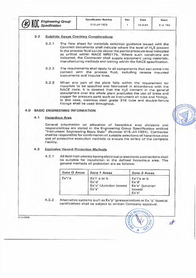
4.2.1
All
field instruments
having
electrical
or
electronic
connections
shall
be suitable for installation
in
the defined
hazardous
area.
The
general
methods
of
protection
are
as
follows:
4.?.2
Alternative
systems
such
as
Ex'p'
{pressurization)or
Ex
,s'
(special
cert¡f¡cationl
shall
be
subject
to wrirten
Company
approval.
Ex'i'a
or
b
Ex'd'
Ex'e'
(junction
boxes)
Ex's'
Ex
Ex
i'a
d'
or b
f¡'g'
(Junction
boxes)
Ex's'
Ex'i'a
Zone
2 Areas
one
1
Areas
ona
O
Areas
Sheet
I of
163
Date
15-9-94
Rev
pecification
Number
01s-JH-1903
@ït|Jßi##,G'¡ouP
d,
N12-0056
7/25/2019 015-JH-1903
http://slidepdf.com/reader/full/015-jh-1903 9/163
4.3
4.2,3
The
preferred
priority
for
the
protection
methods
are
given
in
the
Engineering
Group
specification
entitred
rnstrument
Design,,
(Number
015-JH-1902).
4'2.4
All
equipment
shail
be
certified
for
the
appropriate
area
classificatiof,,
gËrs
group
and
temperature
class
by a'recognized
European
te-s-ring
authority
to
BS
SSO1
(CENELEC
StJndard
En5O.014-O2O
and
O3g),
or
equivatent.
4'2.5
components
of
systems
protected
by
contror
room-mounted
intrinsically
safe
(lS)
isolators
shall
be
ceri¡f¡ed
individuaily
and
shall
be
checked
by
the
contractor
as
a system
including
the
field
instrument,
the
cable
and
the
isolator.
4.2.6
Field instruments
protected
by
an
ls
isolator
do not
require
a
certif
icate
provided
that
a
documented
staternent
f rorn
the
Approved
Manufacturer
is
included
to
confirm
that
the
instrument
may
be
used
as
sirnple
apparatus
in
an lS
circuit
in
accordance
with
BS
S34b.
Protection
from
the
Environment
4.3.1
The
minimum
acceptable
standard
of
protectÍon
against
water
or
dust
ingress
is
to
BS
S49O
(lEC
S29)
degree
of
protectíon
tp
6b.
4-3.2
Electronic
parts
shall
be
environmentally
sealed
or
designed
to
operate
without
change
of
atmosphere (breathing).
4'3'3
Sun
shields
are required
for
all
instruments
for
protection
from
the
direct
sun.
Additional
cooling
måy
be
requírèd
to
ma¡ntain
the
instrument
below
7O C
{165 F}
or
the
max¡mum
Ínstrument
design
ternperatufe,
whichever
is
the lower.
The
contractor
is
responsíb-le
for
providing
such
cooring
either
within
the instrument
design
or
as
a
desÍgn
feature
íncluded
in
the
installation
of
the
instrumãnt.
4.4
Ur¡t¡t¡es
4.5
The
available
utirities
and
their
process
conditions
are
detailed
in
the
EngineeringGroup
Specification entitled lnstrument
Engineeríng
Basic
Data,'
(Number
01s-JH-1901).
Measutqmgnts
and
Scales
The
selected
units
for
calculations
and
scales
are
listed
in
the
Engineering
Group
specification
ent¡tled lnstrument
EngÍneering
Basíc
Data,,
(Number
015-JH-1901).
Sheer
9
of
163
Date
15-9-94
Rev
pecification
Number
01s-JH-1903
@lÏßgHyx,Group
,/'
N 1
2-00s6
7/25/2019 015-JH-1903
http://slidepdf.com/reader/full/015-jh-1903 10/163
TË,t
4.6
Connection
SiF-es
and
Tyoe_
4.6.1
Electrical
All
electrícal
entríes
shall
be
ISO
metric
threaded.
The
preferred
s¡ze is
M2O
x 1.5
mm,
4.6.2 Process
where connection
details
are
given,
it
is
not
âcceptable
for
an
adaptor
to
be
provided
to
meet
this
reguirement,
excepl by
indívídual
Company
agreement.
a
Process connections
for
impulse
tubing shall
be
1/2-in
NpT
female.
b. Process
pipeline
connections
for
therrnowells
shall
be:
1.
Forpípelines
1-1l2-in.
franged,
rared at
30o
fbs.(mínimum).
2.
For
vessels
lbs.(minimum).
2-in.(minimum)
flanged,
rated
30O
c
The flange
rating
shall
increase
to rnatch
the
pipe/vessel
rating
as
necessary.
The
connection
size may
be
increased
if
thermowell stress/vortex-shedding calculations
dictate.
The
gasket
type
and
face
finish
shail
match
the
line
specification.
Atmospheric
pressure
and
cooling
water
applications
rnay
use
NPT
screwed
thermowells.
Pneumatic
l¡nstrument air)
connect¡ons
shall
be
1/4-in.
NpT
unless
air flow requirements
dictate
a
larger
síze. tnstrument
air
tubing/connections
supplíed
as
part
of
the instrument
items
shall
conform
to the
instrument
a¡r hook-up
detaíls
given
in
the Engineering
Group specification
entitled
lnstrument
lnstallation
(Number
0l E-JH-1
g0g).
d.
Level
instrument
chambers
shall
be flanged,
minimum
rating
30o
lbs.
The
flange
rating
shalr
be
increased
to
match
the
vessel rating
as
necessary.
The
gasket
type
and
face
finish
shall match
the
line
specification.
connections
may
be direct
to
the
vesselfor
each
instrument,
but
stand
pipes
shall
be
used
to
avoid
unnecessary
vessel
penetratíons
when
their
use
does
not
impede
on
access,
walkway
clearance
etc.
Ranges
of
instruments
shall
not
be
compromised
to suit
ínstallat¡on
on
stand
pipes.
shutdown
instruments
shall
have
dedicated
vessel
nozzles.
Sheet
10 of 163
Date
1
5-9-94
ßev
pecification
Numbe¡
01s-JH-1903
@¡í0|',,;:sxx^G¡oup
r/'
N
I 2-OOs6
7/25/2019 015-JH-1903
http://slidepdf.com/reader/full/015-jh-1903 11/163
f)
z.
Jb
*
ú
Control
valves
shall be
flanged
and
faced
according
to the
piping
line
classification,
with
a
minimum
rating
of
3OO
lbs. For
fully
welded
lines, individual
proposals
shall
be
submitted to
the
Company for
approval.
f.
Where
possible,
analysis
instruments
shall use
connections as
for
other
instrurnents.
Exceptions
shall
be
submitted
to the
Company
for approval.
g.
Where multiple
shutdown
instruments
are installed
for 2 out of
3 voting,
each
shall
have
a
dedicated
tapping
into
the
process
piping
or
vessel.
4.7
¡nstrument ldentifÌcation
All instrument
¡tems
shall
be
perrnanently
and clearly marked
for
the
following
categories:
4.7.1
Nameplate
Each item
shall be identified
with
a
permanently
fastened
stainless
steel
or
rust-res¡stant
mater¡al
nameplate
comprising:
e
4.7.2
a.
Manufacturers
name.
b. Model number.
c. Serial
number
d.
'
Temperature
and
Pressure
Rating
Of
Wetted
Parts.
e.
*
Voltage
and
Switch
Fating.
f
.
'
Set
Point, Range/Calibration
and
Other
Relevant
Data.
g.
lnstrument
Tag
No.
{Separate
Tag
Plate
Preferred}.
(*
=
where
applicable)
Certification
Plate
(For
Certified
ltems)
Each
certified instrument
shall
have
a certification
plate
giving
as
a
minimum:
a. Type
of
approval
and
mark
of
certifying
body.
b.
Certifying
authority name.
c.
License/certificate number
and
d
Shaet
11
of
163
Date
15-9-94
Rev
pecifícation
Number
01
s-JH-1903
@lïligHlx, -*
fl
1 2-0056
7/25/2019 015-JH-1903
http://slidepdf.com/reader/full/015-jh-1903 12/163
4.7.3
d,
Area
classification,
gas
group,
temperature
rating.
Tag
Plate
Each
instrument
having
a
tag
number
on
the
p&lD
shall be
provided
w¡th
a
stainless
steel
tag
plate
with
the
full
atphanumeric
tag
number
hard
metal
stamped
or
deep
engraved.
The
minimum
dimensions
shall
be
40
mm
x
2s
mrn
x
1.b
mm
(1
in.
x I in.
x
1116 in.)
with
a 2-mm
t1/1O-in.) hole
driiled
In
one
corner.
The
tag
shall
be
fastened
to
the
instrument
with
staínless
steel
wire
of
minimum
1
.O-mm
11 låO-in.l
diameter.
Notet
A
tag
plate
integral
with
the
Approved
Manufacturer,s
nameplate
is
acceptable provided the tagging
is
large, clear
and
easily
read
in
the
final
installed
position.
4.7.4
Equipment
and
Site
Number
Tag
plate
Each
instrurnent
shall
be
allocated
by
the
company
an
Equipment
ldentificatíon
Number
(ElN)
and
a
Site
Number
(SN).
The
Contracror
shall
manufacture
and
fit
tag
plates
bearing
the
allocated
numbers
to
each
instrument.
The
minimum
dimensions
shall
be
as
those
above.
4.8
Limitatigns
on
selectiqn
and
Aooroved
Manufacturers
List
4.8.1
All
instruments
and
instrument
items
shall
be
of
heavy
duty
industrial
type
and
be
suitable
for
use
in
the
stated
environment.
4.8.2
Tried
and
tested
equipment
shall
be
used.
Equipment
approaching
obsolescence
shall
be
avoided.
4.8.3
Aluminium
and
aluminium
alloys
are not
permitted
except
with
company
approval.
where
use
of
such
alloys
cannot
be
avoided,
they
shall
be
of
a
type
suitable
for
use
w¡th
electrical
instruments
situated in
a
hazardous
area,
and
be
fully
protected
against
the
environment.
4.8.4
Manufacturers
shall
be
selected
from
the Approved
Manufacturer's
list.
where
a
suítable
manufacturer
is
not
included
on the
list,
full
details
of
the
proposed
manufacturer
and
the instrument
or
system
together
w¡th
reasons
for
its
inclusion
shall
be submitted
to
the
Company
for
approval.
4.9
Line
Break-.Petection
Line
break resistors
are
required
for
all
contact-type
field
switches.
These
shall
be
f¡tted
in
the instrument
head
where
this
cert¡fication.
Where
this
is
not
possible,
they
may
does
not ín
fringe
on the
at the
nearest
Sheet
12
ol 163
Date
1s-9-94
ßev
pecification
Number
0't
s-JH-1 903
@fff
iz*rm,Group
r/,
Nt
2-0056
7/25/2019 015-JH-1903
http://slidepdf.com/reader/full/015-jh-1903 13/163
available
junction
point
to
the
instrument.
The
type and value
of
the resistor
shall be
agreed
to
w¡th
the
Distributed
Control
System
(DCS)
supplier.
4.1O
Use
ot,Barrier
Glands
4.1o.1
Barrier
glands
shall
be
avoided
whenever possibre.
4.1o.2
Barrier
glands
with
epoxy
putty
filling
shall be
used where
a failure
within
an
instrument
could
allow
a
flammable
process
medium
to
be at
pressure
within
the
terminal
enclosure.
4.10.3
The
contractor
shall
as
a
preferred
option
try
to
ensure
that
the
instrument design
is
such
that
failure
of
the
element
or
capsule
shall
not
cause
the
above
condition,
thus
avoiding
the
need
for
Barrier
Glands.
4.11
Shoo lnsnection
gnd
Testing
The
Contractor
shall
be
responsible
for
all inspectíon
and
testing of
materiats
and
equipment
prior
to
delivery.
No
equipment
or
materials
shail
be
delivered
unt¡l
all applicable
tests have
been
completed
and all
defects
rectified
and
re-tested
successfully.
Documentary
evidence
shall
be
available
for
Company
review if
requested.
4.11.1
Quality
Assurance and
Ouality
Control
a.
All
items
are to be
designed,
manufactured,
inspected
and
tested
under the
control
of
a documented
oA/oc
system,
General
and
specific requirements
are
provided
in
the
contract.
b. special
reference
to
inspection/test
actions
within
the
detailed
sections
of
this
specification
are
additional
to
and
shall not
replace
or reduce
the
oA/oc
requirements
provided
for
in the
Contract.
c
Approved
Manufacturer
specific
data
and
model
numbers
shown on
data sheets
approved
by
the
Company
in
no way
relieve
the
contractor
of
its
responsibility
to
provide
equipment
to
satisfy
the
servíce
conditions
stated on
the
specifications
and data
sheets.
lt
is
the contractor's
responsibility
to
not¡fy
the company
of
any
conflict
with
model
numbers,
materÍals
or
designs
specified.
d.
The
Company
shall
be
permitted
to witness
Approved
Manufacturer's
QA/oc
systems
operating
on
all
instruments
during
design,
fabrication,
assembly
and
testing.
Sheet
13
of 163
Date
15-9-94
Rav
pecification
Number
015-JH-1903
@ffili:*"x,Group
r
12-o056
7/25/2019 015-JH-1903
http://slidepdf.com/reader/full/015-jh-1903 14/163
z
þ
*
.I
ú.
o
The
Contractor
shall
submit
for
Company approval
minimum
inspection
requirements summaries
for
each
item
prior
to
purchase
of
the
equipment.
4.11.2
Shop
Testing
Company
reserves
the right
to
witness
test¡ng
or to
request
addítional
testing
according
to
its
requirements.
Such
witnessing
shall
include
all
control
valves,
relíef
valves,
composite
systems,
control
systems
etc.
The
detailed
requirement
shall
be noted
by the
Company
on
the Contractor's
submitted
Quality
(Test
and
lnspection)
Ptan.
4.12
PaintinLand Protective
Finishing
4.12.1 All
items
shall
be
fully
protected
against
the environmental
conditions,
the effects
of
the
process
fluids,
normal wear
and
the
handling
normally
expected
during
installat¡on,
erection
and
commissioning.
4.12.2
Where
an item
cannot
be rendered
suítable
for
the conditions
by
selection
of
material,
a
paint
finish
shall
be
applied
in
accordance
with
the
Engineering
Group
specifícation
entitled
shop and
Field
Painting
(Number
01s-XH-1OO5l.
Where
the
Engíneering
Group
Specification
calls for Approved
Manufacturers
standard,
an
epoxy
paint finish to
a
recognized
offshore standard
shall
be
the minimum
method of
protection
used.
e
4.12.3
4.12.4
All
Company-approved
aluminium
items
shall
be
fully
coated
on
all
exposed
surfaces.
4.12.5 Mounting
boards,
brackets
and
small moving
parts
not
suitable
for
painting
shall
be
manufactured
from
stainless
steel.
4.12.6
Fasteners
shall
be
stainless
steel
4.13
P_Lckino. Markíng and*DocumentaTion
4.13.1
General
For
all
relevant
requirements,
refer
to
the
Engineering
Group
Specification
entitled
Packing,
Marking
and
Docu.mentation
(Number
O15-UH-1001).
Cadmium
plating
is
not
acceptable as
a
final
finish
Sheet
14 of
t63
Dat8
1
5-9-94
Rev
pecification
Numbor
015-JH-',t903
@t0[fl9ffi#'*ouP
Nt
2-OO56
rl/
7/25/2019 015-JH-1903
http://slidepdf.com/reader/full/015-jh-1903 15/163
,T
*
o
ú
;t
ib
4.13.2
Packing
for
Shipment
a.
lmmediate
packaging
All
items
shall be
packed
in
the Approved
Manufacturer,s
standard
packaging
in
such
a
way
that
unpacking
will
not be
necessary
until
each
item is
required
for
erection.
All
necessary
protection
and
desiccants
shâll
be
included.
Equipmentshall
be
capable of withstanding
transport
and
storage
without
affecting
subsequent
sat¡sfactory
operation.
b.
Delivery
Packaging
Delivery
packaging
is
covered
by
the
Engineering
Group
specification
ent¡tled
Packing,
Marking
and
Documeìtat¡on'.
{Number
O15-UH-1001}.
4.14
For
all
relevant
requírements,
refer
to the
Engineering
Group Specification
entitled
Spare
Parts
and
Maintenance
Requirements
(Number
01S-KH-
1902).
5.O
CONTROL
VALVES
5.1
ApplicableStandardg
ANSI 816.5
Steet
pipe
Ftanges
and
Flanged
Firtings
ANSI 816.1O
Face-to-Face
and
End-to-End
Dimensions
for
Valves
ANsl 816.34
Varves -
Franged,
Threaded
and
werd
Ended
ANSI
816.37
Hydrostatic
Testing
of
Control Valves
ANSI
B
16.104
Control
Vatve
Seat
Leakage
API
RP
55O
Manualon
lnstatlation
of
Refinery lnstruments
and
Control
Part
1
Systems,
process
lnstrumentation
and
Control
BS
1655
Specífication
for
Flanged
Automatic
Control
Valves
for
the
Process
lndustry
BS
5793
lndustrial
process
Control
Valves
(lEc
5341
Sh6et
15
of 163
Datê
1
5-9-94
Fev
peciflcation
Number
01
s-JH-1903
@101,ï: m:x,Gmup
N12.0O56
rp
7/25/2019 015-JH-1903
http://slidepdf.com/reader/full/015-jh-1903 16/163
5.2
Scooe
of Contol Valve
Selection
A
controlvalve
shall
mean any
valve
which
has
a
process
control
function
on
the
plant,
normally
denoted
by havÌng
a
tag number
allocated
on the
P&lD. The following
additional
items
also
shall
be
considered
in
this section:
5.2.1
Actuated
shutoff
or
emergency
shutdown
(ESD)
valves
shall
be
treated as
control
valves
for
the
purpose
of
this
specification,
except where
a
topic
discussed
in
the
specification
specifically
states
control
valve,
and
the
context
identifies
that
the topic
is
relevant
to
modulating
control
valves
only.
5.2.2 Bypass
valves
shall
be considered
in
the
control valve
analysis
where
the
maxímurn
or
minimum
flow
allowable through
the
bypass
could
be
critical
for
plant
safety,
or
where
noise
or an
unusual
process
consideration
may
apply.
5.2.3
5.2.4
Electric motor-operated
valves
{MOVs)
for modulating
duty
are
covered
by
this section
of this
specification.
Electric MOVs
for
on/off
and
ESD
service
are covered
by
the
Engineering
Group
Specification
ent¡tled Motor-Operated
Valves,,
(Number
Ol
5-JH-1907).
2.
Top and
bottom
guided
(1-in.
valves
may
be
top
guided
only).
3. Single
seated
or balanced
trim
with
flow-under
plug.
4.
Flanged
to
ANSI
816.5
with
face-to-face
dimensions
in
accordance
with
BS 1
655/ANSI
Bl 6.1O.
5. Pneumatically
actuated,
spring
return
diaphragm
type.
6.
Fitted
with
pneumatíc
positioner.
7. Positioners
for valves
with
actuators
of
O.2
to l.O
barg
(3
to 15
psig)
spring range
shall
be
flrted
with
positioner
bypasses,
except
valves
in
split range
service.
5.3 Valve
Tvoes_
5.3.1
StandardSelection
a. Control
valves for
normal
service
shall
generally
be:
1.
Plug-type
globe
valves.
Sheet
16
of 163
Date
1 5-9-94
|
Rev
pecification
Number
015-JH-1903
@K[W,:nyx,Group
N
1
2-0056
r//
7/25/2019 015-JH-1903
http://slidepdf.com/reader/full/015-jh-1903 17/163
b. Other
trim
and
guidance
tvpes
may
be used
if it
can
be shown
that
there
are
advantages
in
the
particular service,
e.g.,
cage
guided,
low
dB
trim,
characterized ball
etc.
c
Skirt-guided
trim
shall
be
avoided
except
for
sizes
1
-112
in.
and
less
in
low
DP
service.
5,3.2
Self-ActingRegulators
Valves
shall normally
be
controlled
from
an externalsignalfrom
the
DCS
or
ESD
system
or
fronr
a
local
controlfer.
Self-acting
regulators
may
be accepted
for
some
services
if
it
can
be
shown
that
the
failure
characteristic
will
not
lead
to
dangerous
process
situations
occurring.
Where self-acting
regulators
are
used,
consideration
shall
be
given
to
the
use
of
line-tapped
signals in lieu
of
integral
bleeds.
5.3.3 Valve
Sizes
a.
The
minimum
valve
body
size
is 1 ín.,
unless approved
otherwise, in
writing,
by
the Company.
lf
smaller
sizes
are
approved,
top
guided
only
types may
be
used.
b.
Valves
shall
be selected
from
standard
pipe
line
sizes:
1
in.,
1-112in.,2in.,3
in.,
4 in.,
6
in.,
I
in.,
1O
in.,12in.,
14
in.,
16
in. etc.
Unusual
valve
sizes,
e.9.,
1-114
in.,
2-112
in.,
S
in.
etc. shall
not
be
used.
d.
Valves
in
flashing
service
may, subject
to
Company
approval,
have
larger outlet
size
than inlet
size.
5.3.4
Body
Pressure
Rating
The
mÍnimum
pressure
rating
for
controlvalves
shall
be
3OO lbs
for
sizes
up
to
and
including
f-in.
nominal
bore (NBl.
Larger valves
shall be
line
rated.
Subject
to Company approval,
shutoff
valves
of
quarter-turn
type
may
be accepted
as
split-body
type
and
may
be
at
line
class
rating
(if
the
line is
rated
less
than
3OO
lbs)
in
cases
where
the
piping
system
specifies identical
manual
valves
and
advantages
for
spares
stocking
can be
shown.
5.3.5 Screwed Valves
Screwed-end valves
for
screwed
piping
classifications
or
welded-in
valves
for
extreme service
conditions
may
be
allowed subject
to
specific
approval
by
the
Company
c
Shê6t
17
of
163
Dat€
15-9-94
Rev
pecification
Number
015-JH-1903
@lr0l,Y,: mx,*ouP
N12.0056
rl
7/25/2019 015-JH-1903
http://slidepdf.com/reader/full/015-jh-1903 18/163
G
z
))
*
É
5.3.6
Tight
Shutoff
Valves shall
not
be used
for
dual
purposes
(control
and
shut-
down)
when
leakage
cannot be
tolerated.
lf
necessary,
an
additíonal tight
shutoff
(TSo)
valve
shail
be
added
for
process
interrupt
service
in
cases
where leakage
would
tead
to
a
shutdown.
Valves
used for
control
shall not
be
specified
as
TSO.
b.
ouarter-turn
ball valves
may
be
used
for
on/off
service
on
clean
process
media.
Valves
for shutoff
service
on
dirty
media
shalf
be
specially
selected
for self
cleaning
propert¡es,
e.g.,
cutting
or
shearing
action
on
closing.
Techniques
such
as
seat
flushÍng
or
purging
shall
be
adopted
as
necessary
to
ensure
a
correct
seating
of the
trim.
5.3.7
Butterfly
Valves
Butterfly
valves
may
be
used
on
high-capacity
service
where
low-
pressure
losses
are
essentialand
the operating
differential
pressure
is
small.
The
minimum
allowed
body size
is
2
in.
wafer-type
valves
are
acceptable
provided
alignment
kits
are
part
of
the
scope
of
supply.
5.3,8 Ball
Valves
for
Control
Characterized
ball valves
of
size 1-1lZ
in.
and
upwards
may
be
used where
the available
pressure
drop
precludes
the
use
of
a
globe
valve. lf
the valve
design is
of
flangeless
body
type,
the
valve
shall
be
purchased
with
flange
studs
to
line
class and
an
alignment
kit.
5.3.9 Fotary
Plug
Valves
Low-void,
self-flushing valves
of
rotary-plug
type
may
be used
for
particulate
service
where
process
conditions
allow.
5.3.1O
Angle
Valves
Angle valves w¡th
top-guided
plug
may
be used with
Company
approval.
5.3.11 Three-Way
Valves
Three-way
valves
may
be used
for
mixing
or
flow
splitting
service,
and
may
be top
guided
only.
a
Sheot
II
of
163
Date
15-9-94
Rev
pecification
Number
0 t
5-JH-1
903
ØW, ;v:m:x:-*
N I
2-0056
r/,
7/25/2019 015-JH-1903
http://slidepdf.com/reader/full/015-jh-1903 19/163
5.3.12
Soft
Seats
Globe
valves
for
tight
shutoff
service
in
clean
process
fluids
may
be
fitted
with
soft
seats
for
services
up
to
the
soft
insert
allowable
operat¡ng
temperature.
Lapped
seats, Stell¡ted as necessary, shall
be
used for
higher
process
temperatures.
5.3.13
Failure Action
The
valve
failure
position
indicated
on
the
P lD
shall be
achieved
in
the valve/actuator
design.
Fail
locked
systems
shall have
a
defined
drift
position.
lf
a
drift
position
is not
acceptable, double-
acting
actuators
with
appropriate
reservoir
and
trip
systems
shall
be
used,
as
for
ESD
valves, refer
to
section
5.7
of
this
specification.
5.3.14 Special Applications
Solutions
for
special
applications
or
conditions
not
covered
by
this
specifícation shall
be submitted
to
the
Company
for
approval.
5.4 Va.llre
Sizing
Requirements
5.4.1 Control of
Design Data
Valves shall
be sized
on
the
basis
of
defined
issues
of the
process
data
sheets,
P lD,
equipment
and
piping
data.
A
document
control
system shall
be
maintained
to
ensute that
the valves
are
built
to a
calculation
based
on
the
final
issue
of
data.
Data
sheets
shall
state
the
process
data
revision
number,
and
calculations
the
data
sheet
revision
number.
5.4.2
Limiting
Case
The
valve
purchase
data
sheet
shall
specify
the
applicable
upstream and
downstream
pressures
(or
pressure
difference)
for
all
cases
given.
Where
the
process
conditions
are such
that varying
combinations
of different
process
fluids
can be
ptesent, andlor the
maximum
or minimum
flow
can
occur
at
varying
pressure,
sufficient
calculations
shall
be
performed
to
ensure
that
the
l¡m¡ting
case is
selected
as the
design
case.
5.4.3
CalculationRequired
Valve
sizing
calculations
shall
be
performed
in
accordance
with
BS
5793
(lEC
534).
Valve size
calculations
shall
be
produced
at
least
for
the
rninimum, design
and
over-design
process
conditions,
Additional
calculations,
as
necessary,
shall
be
performed
to
establish
the correct
trim
form.
Valve
ons
shall
also be
Sheet
19
0f
163
Dats
15-9-94
Rev
pec¡flcation
Number
015-JH-1903
ØffilY,wx,Group
N 1 2-0056
r//
7/25/2019 015-JH-1903
http://slidepdf.com/reader/full/015-jh-1903 20/163
-t
Þ
*
E
o
.T
o
t.
performed
for
on/off
valves
(except
full-bore
ball
valvesl
to
confirm
¿dysrsê
process
condítions
are
not
occurring.
The
differential
pressure
for
a globe
valve shall
not
be
less
than
O.7
bar (10
psi)
at
design
flow. For
DP
less
than 0.7
bar
(10
psi),
alternative
valve
types
shall
be selected.
5.4.4
OverdesignMargin
The
valve
trim
shall
be
calculated
so
that
the design
flow is
between
7O
and
8Ùo/o
of the
fully
open
valve
capacity,
except
that
where an over-design
figure
is
also
to
be allowed
for
within the
valve
design,
this
shall
occur at not
gfeater
than
gO%
of
the valve
capacity.
5.4.5
Turndown
The minimum flow
shall be
attainable within
the
turndown
ratio of
the
selected
valve/controller
combination.
The
maximum
turndown
for
standard
valves
shall
not exceed
30
to 1.
For
valves
with
CV
less
than
1,
this
shall
reduce
to
1O
to
1. Special
valves
w¡th
h¡gh
turndown characteristics
may
be
ottered
to
the
Company
for
approval
to suit
special
process
conditions.
5.4.6
Valve
Stroke
The
stroke
of
the
valve
shall be
within the
band
lO%
to
geo/o
for
all
the
above criteria.
5.4.7
Effect on
Relief
System
The
calculation
shall
show
the flow
at
design
and over-design
pressure
when
the
valve
is fully
open.
The
resultíng
over
desígn
on
flow
shall
be
confirmed
against operating
conditions
and
relief
arrangements
to
confírm
plant
safety.
Where
the
flow
through
the
valve
is
critical
to
the sizing
of
a
relief
or
other
safety
system,
the
bypass valve
(if
fittedl
shall
also
be
fully
specified
with
an identícal
valve
characteristic
(CV¡
or
maximum
flow
limit
to
prevent
maloperation
under
bypass
control.
5.4.8
Trim
Capacity
The
selected
valve
shall
be
capable of
accepting
two
trim
changes
up
and
down
from
the finally
calculated
size
to allow for
process
design
changes.
This
may
be
varied,
subject
to
Company
agreement, when:
a. The
calculated
valve
body
is
less
than
1 in.
Sheet
20 of
163
Date
1
5-9-94
|
Rev
pecification
Number
01s-JH-1903
ØKWE##: H,Graup
r{
1
2-0056
7/25/2019 015-JH-1903
http://slidepdf.com/reader/full/015-jh-1903 21/163
r
*
o
t-
b.
The calculated
valve
body
is
two
or more sizes
below
line
size.
A
body
one size
smaller
than
the
line
shall
be
used
wirh
reduced
trim.
5.4.9
Leakage Rate
The
shutoff
flow
tleakage
ratel
shall
be
calculated
at
the
shutoff
design
pressure,
and
the
figure
stated on
the
calculation sheet
and
checked
agaínst
operat¡ng
conditions to
confirm
plant
safety,
and
to confirm
trip
cond¡tions
will
not
arise
during
process
interrupt.
Additional
TSO valves
shall
be
added
as
necessary.
5.4.10
Minimum
Stop
Where
a
minimum stop
is
specified
(based
on
flow), the
appropriare
valve
opening shall be
calculated.
5.4.11
Back
Flow
Where
back
flow
protection
is
required,
the valve
shall
be
checked
to confirm that
the
correct type
of
valve
and
adequate
actuator
force
has
been
selected.
5.4.12
Three-Way
Valves
For
essential
safety
reasons,
three-way valves
shall be
clearly
identified
as to
service,
¡.e,,
flow-splitting
or flow-mixing
or flow-
diversion, and
all operating
combinations
identified
before
making
the
calculation.
5.4.13
Two-Phase
Flow
Suitabte calculation methods
shall be
used
for
two-phase
and
flashing
flow
to
ensure
the
gas
phase
CV
is
properly
considered.
5.5
Trin__S_e_[ection
5.5.1
Characterized
Positioners
Wherever
possible,
the
trim
characteristic
shall
be
specified
so
as
to
obtain
a
linear
installed
valve characteristic
over
the
operating
range.
Characterized
positioners
are only
accepted
where
the
correct
inherent
trim
types
are
not
possible.
5.5.2
Selection
of
Characteristic
The
inherent
trim
characteristic
(or
characterization
in
the
case
of
non-globe
types)
shall
be
carefully
sel
provide
the
best control
compromise.
ected each
application
to
table
(table
1)
Sheet
21
of
163
Dat6
15-9-94
Rev
pecification Number
01sJH-1903
@l0tY, ##,n**
N1
2-0056
,/,
7/25/2019 015-JH-1903
http://slidepdf.com/reader/full/015-jh-1903 22/163
can be
used
to assist
the
selection.
The
Contractor is responsible
for
ensuring
that the
final
trim
selection
provides
control
within
specification.
5.5.3
Small
Pressure
Drops
Systems
shall be
indivídually
assessed
when
the
pressure
drop
across
the control valve
is
less
than
25o/o
of
the
total
dynam¡c
pressure
loss
at
design
flow
rate.
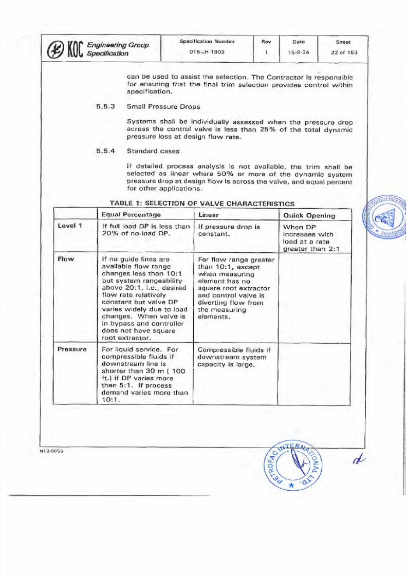
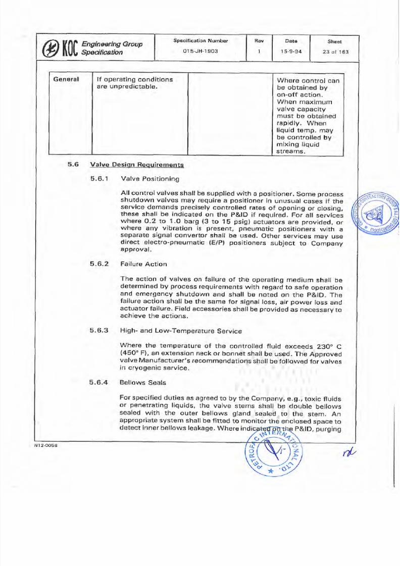
5.5.4
Standard
cases
lf
deta¡led
process
analysis is
not
available, the
trim
shall
be
selected
as
linear
where
5Oo/o
or
more
of
the
dynamic
system
pressure
drop at
design
flow is
across
the
valve,
and equal
percent
for
other applications.
TABLE
1:
SELECTION
OF
VALVE
CHARACTERTSTTCS
Compressible fluids if
downstream
system
capacity is large.
For
liquid
service.
For
compressible
fluids
if
downstream
line is
shorter than 3O m
{
10O
ft.)
if DP varies
more
than
5:1.
lf
process
demand
varies
more
than
1O:1.
Pressure
For
flow range greater
than
1O:'1,
except
when
measuring
element has no
square root
extractor
and
control
valve
is
divertíng
flow
from
the
measuring
elements.
lf
no
guide
lines are
available
flow
range
changes
less
than
lO:1
but system
rangeability
above 2Q:1,
i.e.,
desired
flow
rate
relatively
constant
but
valve
DP
varies
widely
due
to
load
changes.
When
valve
ís
in
bypass
and
controller
does
not
have
square
root
extfactor.
Flow
When
DP
increases
with
load
at a
rate
greater
than
2:1
lf
pressure
drop
is
constant.
lf
full
load DP
is less
than
2Oo/o
of no-load
DP.
Level
1
Ouick
Opening
inear
qual
Percentage
Sheet
22
ol
163
D¿te
1
5-9-94
Rev
peclf¡cat¡on
Number
015-JH-1903
@ïtÏl 'x;m,GrouP
N
1
2-0056
t/'
7/25/2019 015-JH-1903
http://slidepdf.com/reader/full/015-jh-1903 23/163
Where
control
can
be
obtained
by
on-off action.
When
maximum
valve
capacity
must
be
obtained
rapidly.
When
liquíd
temp.
may
be
controlled
by
mixing
liquid
streams.
lf
operating
conditions
are unpredictable.
General
5.6
Valve
Design
Reouirements.
5.6.1
Valve
Positioning
All
controlvalves
shall
be
supplied
with
a
positioner.
some
process
shutdown valves
may
require
a
positioner
ín
unusual
cases if
the
service
demands
precisely
controlled
rates
of opening
or closing.
these
shall
be indÍcated
on
the
P&lD
if
required.
For
afl
servíces
where
O.2
to
1.0
barg
(3
to
15
psig)
actuators
are
provided,
or
where
any
vibration
is
present,
pneumatic
positioners
with
a
separate
signal
convertor
shall
be
used.
other
services
may use
direct
electro-pneumatic
(E/P)
positioners
subject
to
Company
approval.
5.6.2
Failure
Action
The
action of valves
on
failure
of
the operating
medium
shall
be
determined
by
process
requirements
with
regard
to
safe
operation
and
emergency
shutdown
and
shall
be
noted
on
the
p&lD.
The
failure
action
shall
be
the
same
for
signal
loss,
air
power
loss
and
actuator
failure.
Field
accessories
shall be
provided
as
necessary
to
achieve
the
actions.
5.6.3 High-
and Low-Temperature
Service
Where
the
temperature
of
the
controlled
fluid
exceeds
230
C
(45O
Fl,
an
extension
neck
or
bonnet shall
be
used.
The
Approved
valve
Manufacturer's
recommendations
shall
be
followed
for
valves
in
cryogenic
service.
5.6.4
Bellows
Seals
For
specified
duties
as
agreed
to by the
Company,
e.g.,
toxic
fluids
or
penetrating
liquids,
the
valve
stems
shall
be
double
bellows
sealed
with
the
outer
bellows
gland
sealed
to the
stem.
An
appropriate
system
shall
be
fitted
to
monitor
the
enc
losed
space to
P&lD,
purging
etect
inner
bellows
leakage.
Where ind
Sheet
23 of
163
Dats
15-9-94
Rev
pecification
Number
01s-JH-1
903
@ïtÏf,Tn*x,G'louP
N12-0056
r/,
7/25/2019 015-JH-1903
http://slidepdf.com/reader/full/015-jh-1903 24/163
''u
Þ
*
ú,
ñ
of
the interspace
and
a
purge
flow
alarm
shall be
used.
5.6.5
Replacement
of
Trim
The valve
trim
(plug
and
seat,
ball
and seat
etc.)
shall
be
removable.
Access
to
the
trìm
for
globe-type
valves
shall
þe
from
the
top of
the valve.
lf
a
bottom
flange
is
fitted
to the
body
for
access
to
the seat,
this
shall
not
be
drilled
and
tapped
for
drainage
or
pulling.
5.6.6
Opening
and
Closing
Times
and
Valve
Response
a All
data
sheets
shallspecify
the maximum
allowed
opening
and
closing times
based
on
the
process
conditions
and equipment
being
operated. Valves
in
compressor
anti-surge
control
shall
have
a stroke
time not
exceeding
5 seconds.
b.
The
response
t¡me
shall
also
be
stated,
based
on
the
time
for
the
valve
to
complete
¡ts
movement
when the
signal
to
the
pos¡t¡oner
undergoes
a
1Ùo/o
step
change.
5.6.7
Minimum
and Maximum
Stops
Minimum
stops
shall
not
be used except
with Company
approval.
Minimum
flow
shall
be
achieved
by
providÍng
piping
and
valve
bypasses
with
an orifice restriction.
Maximum
stops
shall
only
be
fitted
¡f valve
over-design
cannot
be tolerated
safely.
ln
all
cases
the stops shall be
based
on
the
calculated
stem
positíon
for
given
flow and
pressure
conditions. The
stops
shall
as
a minimum
be
double
nut
locked
and
shall
be
permanently
secured,
preferably
by
welding,
after
proving
during
commissioning, The
stop
mechanism
shall
be
picked
out
in
a
contrasting
colour
to the
valve
and
actuator.
5.6.8
Seat
Leakage
Valve
data sheets
shall
state
the
seat
leakage
to be
tolerated.
Generally,
valves in
depressurising,
shutoff
and emergency shut-
down
shall
be specified
class
V
and
for
process
shutoff
shall
be
specified
to
class
lV
of
ANSI
B1
6.1o4.
Bubble-t¡ght valves
shail
be
specified
for
shutdown of
flammable
fluids
for
supply
to
end
users
such
as
the fuel supply
to a
fired
heater,
and for
all
total ESD
applications.
5.6.9
Gland
Packing
For
normalservice
on
clean
fluids,
a
bolted
bonnet
with
gasket
and retaining
recess
shall be
f¡tted,
packed
with
interlocking
self-lubrícating
packing
of
the Tefton
il
type. Lantern
a
Sheet
24
of 163
Dats
I
5,9-94
Revpecification
Number
01s-JH-1903
@ï|Jfg x :x,GrouP
N12-OO56
rlt

7/25/2019 015-JH-1903
http://slidepdf.com/reader/full/015-jh-1903 25/163
Packing
for
valves
above
S4O C
(1OOO F)
shall
be
the
subject
of
individual
agreement
with the
Company.
Low-temperature
service,
minus
ES
to
ooc
(minus
67
to 32 F)
shall
use
solid
teflon
V-rings
with
an
extended
bonnet
and
thermal
isolation
suitable
for
the
service.
ring
and
spring
followers
shall
be
used
For
higher
temperatures,
205
to
540 C
(400
to
1OOO FI,
solid
graphiie
packing shail
be
provided,
with
braided
packing
where
sorids
may
be
deposited
on
the
stem.
Finned
bonnets,
cooling
rings
and thermal
isolation
techniques
shall
be
used.
For
higher
tempsratures,
205
to
54o c
{4oo
to
1ooo F},
solid
graphite
packing
shall
be
provided,
with
braided
packing
where
solids
may
be
deposited
on the
stem.
Finned
bonnets,iooling
rings
and
thermal isolation
techniques
shall
be used
as
necessary.
b
e.
g
5.6.1O
Gland
Lubrication
5.6.1
1
c
d
t
Packing
shall
be
accessed
through
adequately
sized
bofted
stuffing
boxes.
The Approved
Manufacturer's
instalrations
instructions,
e.ç1.,
bonnet
over
or
under
body,
side-mounting
restrictions
etc.
shall
be strictly
followed
to
prevent
damage
occurring
to
the
packing.
other
packing
materiars
and
methods
may
be
offered
for
Company
approval
by
submitting
full
details,
accompanied
by
lhe
Approved
Manufacturer's
statement
of
the
advantages
offered.
All
glands
shall
be
drilled
and
tapped
for
lubrication
units
even
where
packing
is
self-lubricated.
Lubricators
shall
only
be
fitted
as
necessary.
un-used
tappings
shall
be
plugged.
The
plug
material
shall
be
compatibfe
with
the bonnet
marerial. Lubricatorõ
for
high-
pressure
valves
(greater
than 1S
barg,
i.e.,
220
psig
)
shall
have
an
isolatíng
valve
fítted
between
the
tubricator
and
the
stuffing
box.
Direction
of
Flow
The
direction
of
flow
through
the valve
shall
be
clearly
and
indelibly
marked
on
the
body,
preferably
by
a
cast
on
arrow
or stamped
plate.
Sheet
25
ol
163
Date
1
5-9-94
|
Rev
pecification
Number
01
5-JH-r
903
@fff,?,:J##,Group
i
I
H
H
Ë
li
i:
t:
(_'
l;*:
o
,Y
{
o
ú.
*
N
I 2-0056
rP
7/25/2019 015-JH-1903
http://slidepdf.com/reader/full/015-jh-1903 26/163
5.7 Actuator
Selection
and
Sizing
5.7.1
Selection
The
actuator
shall
be
purchased
together with
the
valve
as an
integrated
package.
Where
the
actuator manufacturer
is
not
on
the
Approved
Manufacturer s
list,
the
selection
is
sublect to
Company
approval.
b.
Actuators
shall
normally
be
pneumatic-diaphragm
type
for
globe
valves, plug
valves
and
butterfly
valves
and
pneumatic
spring return
piston
actuators
of
scotch
yoke
or
geared
type for
on/off
quarter-turn
valves.
c.
Piston actuators
of
air
or hydraulic
type
may
be
used
with
Company approval
when
it
can be
shown
that
long
strokes,
high
forces,
speeds
etc. are
essential.
d, Motor-operated
modulating
valves,
piston-operated
pneumatic
actuatofs,
airloil
systems
or
other
special
actuation
methods
may
be
used
in
special circumstances
subject
to
Compan
approval.
e.
For
controlvalves
the
normal
pneumatic
actuator
spring
range
shall
be
O.2
to
1 .O
barg
(3
to
t b
psig),
to
enabte
positioner
bypasses
to
be
fitted.
lf
it
can be
shown
that
a bypass
is
not
necessary
or undesirable,
or
if
circumstances
demand
a
higher
force
or
a
higher
speed
than
is
available
from
1.O
barg
(14.5
psígl,
an
alternative
spr¡ng
rate
may
be
used,
subject
to
approval
by
the
Company,
Under
no
circurnstances
shall
the
spring
rate
exceed
4,0
barg
(6O
psig).
The
actuator shall
be
able
to
w¡thstand
a mechanical
design
air
pressure
of
1
1.3
barg
1164
psig).
f.
Pneumatic
piston
actuators
are
to
be
sized
to supply
the
full
specified force
at
an
air
pressure
no
greater
than 4.O
barg
(60
psig).
5.7.2
Actuator
Sizing
Criteria,
Control
Valves
a The
actuator
shall
be
able
to
overcome a
minimum
of
125o/o
of
the
worst predictable
process
and
mechanical
forces
withín
the
valve,
inclusive
of
fluid
shutoff
pressures,
coking
or
solids,
gland
compression,
stíction
and friction
and
all
other
expected
or
possible
forces.
As
a
minimum,
the
process
force
shall
be
taken
as the
upstream
process
design
pressure
(or
the
piping
mechanícal
design
pressure
if
the
actuator size
resulting
from
this is
economicl
and an
atmospheric
downstream
pressure.
Where
this
calculation
results
in
actuator,
or
a
Sheet
26of163
Date
15-9-94
Rev
pecification
Number
015-JH-1903
@ïr0l ;lglx^G loup
(,
..
;:)
Þ
N
l2-0056
*
rft
7/25/2019 015-JH-1903
http://slidepdf.com/reader/full/015-jh-1903 27/163
c
one
which
is
too
large
to
provide
an
adequate
speed
of
response,
the
overall
solution shall
be
subject
to
Company
approval.
b.
lf
back-flow
protect¡on
is
pafi
of
the
valve
service,
the actuator
shall be
capable
of
the necessary
forces
to
achieve
the
operat¡on.
Sizing
criteria
for
actuators
for
three-way
valves
shall
be
chosen
to
enable
the
valve
to
operate
against
the
worst
maximum
design
differential
pressure
across
a
single
port.
All
the
operating
scenario
shall
be
reviewed
to
confirm that
the
worst
case has been
foreseen.
d.
The
selected
actuator
sizing
criteria
shall
be clearly
stated
on
the data
sheet.
For
pneumatic
actuators,
full
details
of
the
minimum,
maximum
and spring
design
air
pressures
shall be
noted.
e.
The
actuator shall
be
sufficiently
powerful
that bench setting
for
achievement
of
specified
leakage
rate
is not
required.
Actuator
Sizing Criteria,
Emergency
Shutdown
Valves
a.
Calculation
Requirements
1.
This section
applies
to
all
valves
controlled
directly
from
the
ESD
logic.
including
vent
valves
and
de-pressurizing
valves.
2. As
shutdown valves
spend
long
periods
without
cycling,
particular
care
shall
be
taken
to
ensure
that
the
actuators
deliver
sufficient
force
to
fully
open/close
the
valves
at
the
extremities of
operation when
called
upon
to
do
so.
Due
regard
shall
be
paid
to
the
possibility
of
sticking
and
gummy
deposits
on
valves
which
are stationary
for
long
períods.
3.
The torque
/
linear
force
delivered
by the
actuator
at the
minímum
air
design
pressure
shall be
at least
double
the
calculated force
for
the
most
arduous
of
the
following
conditions
or
combination
of
conditions,
and any
other
restrictions
applicable
in the
particular
application:
a.
Breakaway
force,
b.
Running
force,
c. Re-seat
force.
5.7.3
Shېt
27
ol 163'
Date
15-9-94
Rev
pecification
Number
01 s-JH-1903
@ft[ß,: *W^Group
N1 2-0056
d,
7/25/2019 015-JH-1903
http://slidepdf.com/reader/full/015-jh-1903 28/163
Gland
or
packing
forces
Coking,
dirt,
rust
or
gumming
clearance forces,
ínternal
and external.
Safety factors
on
all
the
figures.
Positive
tolerances
on
all measured
figures.
4. The
design check
shall
ensure
that
the
other
mechanical
components
of the
valve
are
specified
with
sufficient
strength
to
utilize
the
forces
of the
oversized
actuator.
b.
Actuator
Selection
1.
Actuators
shall normally be
diaphragm
type
when
globe
valves have
been
specified
for
shutdown duty,
and
spring
return
p¡ston
actuators
operat¡ng
through
a
scotch
yoke
or
gearbox
for
quarter.turn
type. Where
a
pneumatically
powered
shutdown
valve
is
in
a
servÍce
where
the
standard
spring
return
system
is not
suitable
due
to
return
force
or
closing
speed
restriction,
a double-acting
or
spring-assisted
system
shall
be used.
2.
The
requirernent
and
method
of
operating
double-acting
actuators
shall
be indicated on the
P lD,
with
the speed
parameters stated.
c. Actuating
Method
d
e
f.
g
I'
\
1
Generalfy,
the
actuation
method
for
ESD,
vent
and
de-
pressurizing
valves
shall
be selected from
two
types:
a
Direct
Pneumatic
Type
The
actuator
shall operate
directly
on
air
supplied
from
a
dedicated
reservoir.
b.
lndirect
Hydraulic Type
These valves
shall
be
operated
by
an
air-driven
hydraulic
package.
The
air
shall be
supplied from
a
dedicated
reservoir.
2.
For
both
types,
the
air
reservoir
shall be supplied
with
sufficient
reserve
capacity
to enable
three
complete
valve
operation
cycles.
The
reservoir
shall
be
sized
for 3-full
strokes
of the
valve
with
a
50o/o
safety
factor.
The
reservoir
may
be
dedicated
to
a
or
to a
group
Sheet
28of
163
DatB
15-9-94
Rev
pecífication
Number
01s-JH-1903
@lr0l,';*w,GrouP
N
l2-OOs6
rþ
7/25/2019 015-JH-1903
http://slidepdf.com/reader/full/015-jh-1903 29/163
*
,b
iL
ú
of
valves when
the
service
of
these
valves
is
strictly
related
and controlled
by the
same
ESD
logic
sequence,
and
the
valves
are
positioned
within a 5-m
pipe
run
from
the reservo¡r.
3.
The reservoir
shall
be
charged at
the normal
Facility
instrument
air
pressure.
The
supply
to
the
reservoir
shall
incorporate filters and check
valves
to
ensure
that
the
air
supply
for
the
ESD
valve
is
retained
during
loss
of
general
air
pressure.
The
design
pressure
for
reservoir
sizing
purposes
shall
be
the
same as the
actuator sizing
design
pressure,
which
shall
not
exceed
4.O barg
(6O
psig).
d.
Trip
Action
The
trip
action
shall be
initiated
in all
cases
by the
de-
energisation of a soleno¡d
valve(s)
powered
from
the
Facility
ESD
system,
for
all
situations
including
reset,
ESD
trip or
controlled
vent action
and any
air
failure
actuation
result¡ng
from
the reservoir low-low
pressure
switch signal.
2.
For
the
low
air
pressure
alarm
and safety
act¡ons,
electronic
pressure
switches
shall
be
fitted
to the
reservoir
to detect
when
the air
reservoir
pressure
is at
15o/
(low
alarm) and
at
5% {low-low trip)
above
the
reservoir
sizing
pressure.
The low
pressure
switch
shall
bring
up
DCS
alarm
to
warn of
a
possible problem
on
the
air
supply.
the
low-low
pressure
switch
signal
passes
to
the
ESO
system,
which
will
institute the
necessary action
on
the
logic
system
as
follows:
â.
Single-Acting
(Spring
Return)
Actualors
Unless
otherwise specífied,
the
low-low
pressure
switch
input
will
prevent
further
use
of
air
toward
the
plant
unsafe
(run)
condition
but allow
manual
selection of
a
trip
to the plant
safe condition. The
valve
will
thus
stay
in
the
Run
condition
until
the
air
pressure
drops
below
the
spring-return
force,
the
spring
will
then
drive the
valve
toward
the
safe
position.
b.
Double-Acting Actuators
Unless
otherwise specified,
the
low-low
signal
shall
cause
a
trip of
the
valve
to
the safe
position
while
there
is
stíll
sufficient air
to ensure that
the
valve
can
be
moved
to
the
safe
position.
1
1
Rev
pecification
Number
01sJH-r 903
Øtí017,1#,#^Group
Shoet
29
of
163
Date
15-g-94
N12-OO56
rf
7/25/2019 015-JH-1903
http://slidepdf.com/reader/full/015-jh-1903 30/163
lt
.l-
ú
*
3.
At
Company
option,
alternative
strategies
may
be
adopted.
The
Contractor
shall
submit
full
details
of the
philosophy,
the
hook-up
and
proposed
field
and
control
room-mounted
instrument
and operator ¡nterfâce for
Company
approval.
4. The
ESD
logic
shall
not
be
self-resert¡ng. The
solenoid
valve
shall
be
of
mechanÍcally
self-resetting
type,
but
shall
require
electrical
reset
by
operation
of
a local
pushbutton
open/close
stat¡on
interfacing
with the
ESD system,
operable
when
the
log¡c
has
been
enabled
by the control
room
operator.
Details
are
provided
in
the
Engineering
Group
Specification ent¡tled
Emergency
Shutdown
Panel
(Number
Ol
5-JH-10951.
5.
Where
an
ESD
valve is also
used
to
perform
a
process
interrupt
function,
an
additional
solenoid valve
shall
be
supplied. This
shall
be
operated
from
the control
logic
and
shall be
so
positioned
and
piped
that
the
ESD function
shall overrule
the control
function
in
the
case
of
an
ESD
trip.
5.7.4
Actuators
for
Motor-Operated
Valves
(MOVs)
MOV
actuators fall into
two service categories:
Direct
motor/gearbox
drives
for
direct
application
to
the valve
stem
in
on/off
application
(no modulation) are covered by the
Engineering
Group
Specification entitled
Motor-Operated
Valves
(Number
01
5-JH-1
907).
b.
Electric
MOVs for
modulating
service:
actuators in
this
category
shall only
be used
when
stipulated
or
auThor¡zed
by
the
Company.
The
actuator,
electr¡cal
controlcard
and
power
control
gear
shall
all
be
purchased
as a fully
integrated
matched
set.
The
actuators
can
be used
in
closed-loop
service,
or
open
Ioop
with
valve
position
feed
back
by
precision
potentiometer.
The
actuator
shall
be fitted with
torque
and end
of travel switches
that
shall override
the control
signals.
The
actuators
must
be certified
for
use
within
the
hâzardous
area
classification
of
the
Facifity,
5.8
Actualor Cpnstruçt¡on
5.8.1
DiaphragmActuators
ct
The
pneumatic
diaphragm
actuator
shalf
be of
totally enclosed
spring-return
type.
a
Sheet
30
ol
163
Date
1 5-9-94
Rev
peclfication
Numbsr
015-JH-1903
Øtí01';y,:xx^G,oup
rd
N12.oos6
7/25/2019 015-JH-1903
http://slidepdf.com/reader/full/015-jh-1903 31/163
b.
The
actuator
shall
be
direct
or
reverse
acting
according
to
the
required
process
failure
action. Within this constraint,
direct
acting
(spring
up)
actuators
are
preferred
in
the
sandy
environment due
to
the
avoidance
of a shaft
seal
and
wiper.
The spring shall
be
of
linear
characteristic
over the
stem travel
range,
and be
corrosion
resistant.
d.
A
spring
screw
and
locknut
shall be
readily
placed
for
adjustment.
e. The
yoke
shall
be
of
cast steel
or
ductile iron,
adeguately
painted
or
plated
against
the
environment
in
accordance
with
the
Engineering Group
Specification
ent¡tled
Shop
and
Field
Painting
(Number
015-XH-1OO5).
A valve
position
indicator
shall
be
f¡tted,
synchronized
and
scaled to
match
the
actual
valve
stroke. The
connect¡on
to the
valve
stem
shall
be
a
threaded split
clamp with
clamping
bolt.
f. The
diaphragm
construction.
case
shall
be
of
botted
pressed
steel
g.
The
diaphragm
shall
be of
nylon
reinforced
neoprene
or
Buna
N. the
maximum
alfowable
deviation
from
the rated
effectíve
area
shall
not
exceed
plus
15%
and
minus O%
through
the
ent¡re
travel.
5.8.2
Ouarter-Turn,
Piston-
and Cylinder-Type Pneumatic
Actuators
a Only
heavy
industríal
types shall
be
accepted.
The actuator
shall
preferably
be of steel
with a chrome-plated
bore,
or
stainless
steel.
High-grade aluminium
with
a
suitable
coating
system
rnay
be
used,
subject
to
Company approval.
b.
The flow
sheet
for
materials
selection
guidance
issued with
the
Contract
documents
shall indicate
where
the
level
of
HrS
present
in
the
process
fluid
can
be
above
the
partiat
pressure
level
indicated
as
critical
within
the
NACE
MR0175.
When
any
part of the
plant
falls within
the
requirement
for
materials
and
fabrication
to
be
in
accordance
with
the
NACE
code, it is
deemed
that
the HrS content
of
the
general
atmosphere
over
the
whole
Facility
requires
rhe use
of solid
stainless
steel
actuators,
also
in
these
circumstances,
chrome
plating
is not
permitted.
c.
The
mechanism,
shafts
etc.
shatl
be
adequately
protected
against dust ingress.
lf
bellows
are
used, the
design
shall
protect
against
dust
being
drawn
in
due
to air change
during
operation.
Exposed
shafts shall
c
IÆffiRW
. Tie
rods
and
other
exposed
fastenings
shall
Sheet
31
of
'l
63
Date
1
5-9-94
Rev
pecification
Number
01s-JH-1903
@fr|JW,ym,Group
N 1 2-0056
t/
7/25/2019 015-JH-1903
http://slidepdf.com/reader/full/015-jh-1903 32/163
d.
Ports
shall
be
a
minimum
size
114-in.
NPT.
Smaller
ports
wíth
adapters are
not acceptable.
Ports
of
at least
114
in.
of
other
thread
forms
shall
be
accepted
provided
they are fitred with
permanenl
NPT
thread
form
adapters.
Exhaust
ports
shall
be
fitted
w¡th
a
silencer/sand
screen.
e
An
external
pos¡tion
indicator
and
inductive
type
cert¡fied
l¡mit
switclres
(in
a
protective
box)
shall
be
fitted.
5.8,3
Hydraulic
and
Special-Purpose
Actuators
A
detailed
specification
and analysis
of all
proposed
actuators
shall
be
presented
to
the
Company
for
approval.
5.9
Nols_e, Flashing
and
Cavitation
5.9.1 Noise
The
Company
shall
be
informed
of
atl
cases where
the
predicted
noise
level
of
a control valve
or
its
bypass
valve
approaches
to
within
3
Db
of
the
maximum
permitted
noise
level
of
85 dB
A,
or
any
lower fígure
stated In
the Engineering
Group Specífication
entitled
Plant/Equipment
Noise
Control
(Number
015-NH-1104).
ln
all
cases
where
it is
necessary
to
use
specia¡
control valves,
silencers
or
other
devices,
they
shall
be
subject to
the
prior
approval
of
the
Company.
b.
Where
the
outlet
pressure
is
less
than
half
the
inlet
pressure
in
the
design case, valve
noise
will
probably
occur
at normalduty.
noise-reducing
trim
shall
be
specified
as
standard
for
these
valves.
Control
valve
noise
shall
wherever
possible
be stopped
at
the
seurce.
The
preferred
design
priorìties
are:
1
.
Re-appraisal
of
the
process
design or
arrangement
to avoid
the
root
noise
cause.
2.
Selection
of
a
suitable valve
and
trim
type.
3. Lo-dB
plates
downstream
of
the
valve.
4.
lnsulation
of the
valve
and
downstream
píping
Geographical
relocation
of
the
equipment
items
and
piping
to
enable
externalscreening
to
be
considered,
ol
valves
to
be away
from
personnelareas.
This
approach
can
only
be
used
when
the
valve
noíse
contribut¡on
does
not cause
the
global plant
noise
to
exceed
the
stated
limits.
a
c
5
Shaat
32
of 163
Dato
15,9-94
Rev
pecification
Numbe¡
01s-JH-1
903
@WF;:ç*,Grvup
N1 2-0056
(p

7/25/2019 015-JH-1903
http://slidepdf.com/reader/full/015-jh-1903 33/163
Valves
shall
be
selected that
are specially designed
for
these
services.
Valves
of
low
recovery
type,
using
frictional
paths,
multiple
port
cages,
vortex flow
or
other
methods
of
velocity
and
anti-cavitation control
shall
be
specified.
5.9.2
Potential
Flashing
and/or
Potential
Cavitating Service
a
b.
Potential
blockage
of
the
trirn shall
be
carefully
considered
when
selecting
fow
recovery
valves.
Design
appraisal
shall
be
conducted
to
confirm
that
any
particulates
or
sludging
present
in
the
process
will
not
block the
passages.
Normally, drillings
less than 3-mm
(1/8-in.)
diameter
shall
be
avoided.
5.10
Construction
Fequirements
5.10.1
Pressure
Envelope
The
pressure
envelope
is
defined
as
all
parts
of
the
valve
whích,
if
a
failure
occurred,
would
allow
process
fluids to
be
released to
the
atmosphere.
This
includes
the
body,
bonnet,
flanges,
plugs
and seal
plates
and
any
other
part
retaining
the
pressure.
b. The
pressure-part
materials
shall
be
equal
to
the
line
specification for
piping
class valves
in
the same
service.
The
Approved
valve
Manufacturer
shall,
however,
confirm that
the
mater¡al is
fit
for the service
and
the mechanicaldesign criteria
stated
on the
data
sheet.
ln
the
¡nterests
of
standardization,
a
higher
grade
of
material
may
be
offered
to
cover
a
number of
services;
however,
the
metaflurgy
shall be
individually
verified
by the
Contractor
as
suitable
for
the applicable
service
conditions.
d.
Forged
materials
shall
be used
throughout
except
with
Company
approvaf
for alternatives.
5.1O.2
Valve
Trim
The
valve
trim
is
that
part
of the valve
which
controls
the flow
of
fluids.
This
includes
the
välve
seat
and
plug,
ball
etc.,
the
stem, the
cage
and
any
other
renewable
parts
separate
from
rhe
body.
b. The
materials
for
the
valve
internals
shall
be
selected
for
the
individual
service.
with
a
minimum
reguirement
of 316
stainless
steel.
For
special
services,
the
Approved
Manufacturer s
recommendation
shall
be
offered
for
approval
by
the Company.
d
c
a
Date
15-9-94
Rev
pecification
Number
01s-JH-1903
@lffi
:,v,äw,Group
Sheet
33 of
163
N r
2-0056
rp
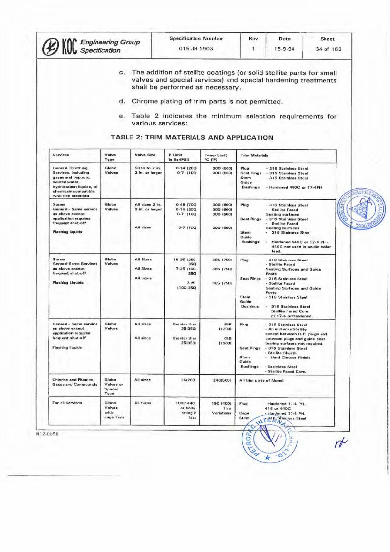
7/25/2019 015-JH-1903
http://slidepdf.com/reader/full/015-jh-1903 34/163
c
The
addition
of stellíte
coat¡ngs
(or
solid
stellite
parts
for
small
valves
and
special
servicesl
and
special hardening
treatments
shall
be performed as necessary.
d,
Chrome
plating
of trim
parts
is not
permitted.
e
Table
2
indicates
the
minimum
selection
various
services:
requirements
for
TABLE 2: TRIM
MATERIALS
AND
APPLICATION
Servlca¡ Vrln
lyP"
Vôlva S¡2. P L¡rlr
ln B rlPsl)
Temp Limlt
"c
fFt
Ttlm
M.tedrl¡
G"nerrl
Thrcttl¡ng
S6rvicrs, includin0
oåBss
and vâpours,
noutrrl water,
hydroc¡rbon
liqukla,
ol
chemic¡l¡ comÞ¡tlble
whh trim mltrr¡¡l
Globo
Valvaa
Sízas
to
2 in.
3
in.
or
larget
o.14 t20ol
o.7
(root
3OO
t6OOl
300
16001
Plu0
Seöt
Ring6
Stem
Guidc
Buchinqs
31
6 St ¡nle8¡ St€.|
3l 6 St.inlsss
Steel
316
Ståinbßß
Steel
Hardened 44OC
or l7-4PH
Steãm
Ganer¡l
-
Samc scruice
g abovc cxcopt
ðppl¡clt¡on
raqu¡rBs
frcqusnt
¡hut-oft
Globc
Valvca
All sizc¡
2
ln.
3 in. or larger
s49
lTOOl
0-t4
l2ool
(}7
troot
300
t600t
300
1600t
300
t6001
Ruc
Seat Rlnga
-
Stellitö Fåced
So¡tino
Éurr cât
-
316
St¡inbsr
Stæl
-
Stellita F¡ccd
Scat¡ng
Surflcâr
-
316
Str¡nl.ß
Stâol
All ¡izc¡
G7
llool
300
t600t
Flárh¡ng ltquadr
Slom
Guido
Buahinge
-
Hrrdcnad 44OC
ot 17-4
PH
-
44OC not
u8.d in
¡c¡dic
boilar
l6üd.
Sta m
6ónorrþSðm
Seruices
ås rbova
lxccpt
lraquent
chut-off
Globo
Vålv6s
All Sizo¡
All
S¡zs¡
All
Sizes
1
8-25
(25ù
35Ol
7-25
t10G'
sSol
385
t7501
385
(75Ot
385
1750t
Plug
-
31
6 St¡¡nlcsE
St.rl
-
slcll¡Îô Fåcàd
S€at¡ng
Surflcr3
and Guidc
PostB
.
316
Str¡nlo¡E
St€rl
'
Stâllitr Fac6d
Sartino
Sur{rcc¡
¡nd Guida
Posts
-
31
6
Sta¡n¡6s3
Stâ.|
S.rt
B¡ngs
Flaehing
Liquidc
7-25
(10G350t
Stem
Gu¡do
BuEhinos
31
6 Stå¡nl'¡¡
Stael
St€llho Fåccd
Corr
or 1 7-4
or Hardcncd.
Grnorrl
-
S¡mc ¡oruica
sc ôbovc
rxcapt
¡pplic¡tíon
roquiro¡
lrcqu¡nt shul-oft
Globo
V¡lvc¡
All
siza¡
Graater
than
2s{35Of
645
fi
200t
Plug
-
316
Strinlô6;
Stool
-
All
curfaccE Stsll¡to
oxcapt
bôtween
D.P.
pluge
and
baween
pluge
Énd
guids
poBt
tôar¡ng
surfsc€¡ not
required.
-
31
6 Str¡nlrss
Stoel
-
Stêil¡l¿
Shoath
-
Hard
Chrome
Finiah
All
sizes Grester
thrn
25(3501
6 ts
ll
2001
Fl6ßhing liquids
Sàrt R¡ñgs
Stcm
Guid¡
Bushinge
-
Sta¡nlGs3
Stc6l
-
StÊllito
F¡ced
Corr.
Chlorine ¡nd
Fluorino
G¡scs
¡nd Compoundg
Globc
Valvoa or
Spacer
Typo
All ¡izcg
1
4(2001
246(5001
All
lrim
part6
of
Monel
For
rll
S ruicas
Globe
Valvoe
w¡th
1OOll44Ol
or body
rlting
¡f
lss
s
1
90
(4001
Trim
Vsr¡at¡onG
Plu0
-
Ho¡dened
I 7-4 Pll
41
6
or
44OC
Cagc
Stom
t 7.4
PH.
TÊ1
câgô Tr¡m
All
SizaÊ
St..l
Sheet
34 of
163
Date
15-9-94
Rev
peciflcation
Number
01s-JH-1903
@|ffi
?,v:#":H,Group
l
i
I
i
I
I
I
I
i
I
I
I
I
I
i
I
I
I
I
I
l
I
¡
l
¡
I
5
h
Ë
fi
F
ll
_.[],
o
ú
N
1
2-0056
*
rf
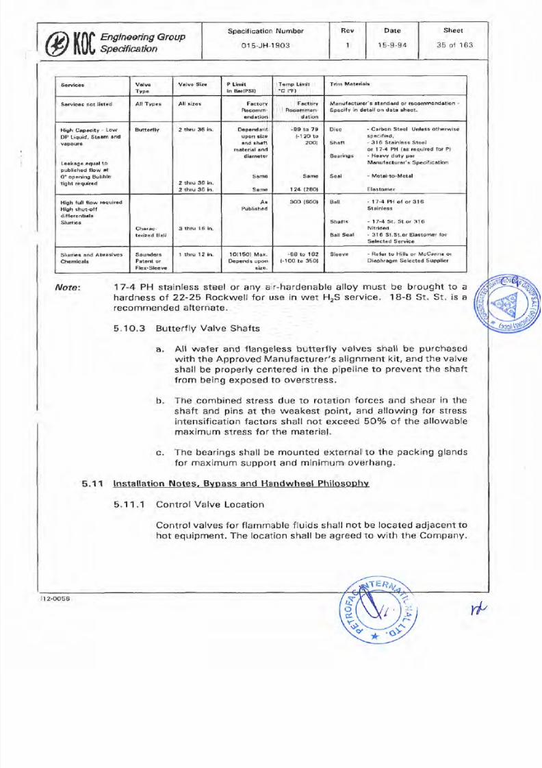
7/25/2019 015-JH-1903
http://slidepdf.com/reader/full/015-jh-1903 35/163
Ølr0l,,;y" ;xx,Group
1
Rev
pecification
Number
01s-JH-1903
Sheet
35 ol
163
Date
15-9-94
Sleeve
.
Bet€r to
Hills
or McC¿nna
or
D¡âphrâgm
Selecl€d
SuÞpl¡er
-88
to 162
l-lO0
to
3501
1O(l50)
Max.
Depends upon
e ize.
1
thru
12 in.
¿und6r8
Prtcnt
or
Flex-Sleeve
Slurr¡€s
rhd
Abras¡ves
Chemic¡ls
Ball
.
17.4 PH
of
or 316
Sta¡nless
Shalts
Ball
Seal
-
17-4 St^ St.or
316
Nitr¡dBd
-
31
ô St.st.or
E¡ôstomer
lor
Sålâctod
Service
3OO
(600)
e
tublishôd
3
rhru 16
ìn.
harac-
tc¡ized B¡ll
High
lull llow
tcquired
Hl0h shut-olf
dìllðrðnt¡rìs
slurries
Disc
Shâlt
Boarings
-
Ca¡bon
Sto€l
Unlcss
otherwise
spèc¡li6d.
-
316
Stâinlesr
Steol
or
l7'4
Ptl
(¡e
r¿qulrod
lor
Pl
.
Hoâvy
duty
por
Mônufu
clursr' 6
Sp€c¡licâtion
Seâ¡
-
Ârelål-lo-Motrl
ElÀBtomer
99 tô
79
(^'l
20 to
2001
$¡me
r
24
(2801
DëÞeñdant
upon
¡ize
and sh¿ft
materiàl
ând
dirmctet
Same
Sårnð
2
thru
36
in.
2
thru
36
in.
2
lhru
36 in.
Buttorfly
¡gh
Capäcity
-
Low
OP
Liquid,
Sta¡m
and
våpour8
Lork.gê
âquål
to
publ¡chod
flow
tt
O'opaning BuÞble
tight requ¡r€d
Manufrcturer's
strñdôrd
or rocommsndåt¡on
Spocily
in dotô¡l
ôn dôt¿
3heet.
Fåctory
Rsôomman
dât¡an
FãaÎory
Rscomm-
ênd t¡on
All
¡i¿os
ll Typas
arvic6s
nol l¡stèd
Tdrn
MttetiâlE
emp
Lirir
"c
rF)
P
L¡rn¡t
ln
BtrlPSt)
Valve
Slze
alve
Type
seruices
Note
5.11
17-4
PH
stainless
steel
or
any
air-hardenable
alloy
must
be
brought
to a
hardness
of 22-25
Rockwell for use
in wet HrS
service.
18-8
St, St, is
a
recommended
alternate.
5.1O.3
Butterfly
Valve
Shafts
All
wafer
and flangeless
butterfly
valves shall
be
purchased
with
the Approved
Manufacturer's
alignment
kit,
and
the
valve
shall
be
properly
centered
in
the
pipeline
to
prevent
the
shaft
from
beíng
exposed to
overstress,
b. The
combined
stress due
to rotation
forces
and
shear
in
the
shaft
and
pins
at
the
weakest
point,
and
allowing for
stress
intensification
factors
shall
not
exceed
50%
of
the allowable
maximum stress for the
malerial.
c.
The
bearings
shall be
mounted
external
to
the
packing glands
for
maximum
support
and
minimum
overhang.
lnstÊllation
Notes.. Bypasq
and Ha0dwheel
Philosophy
5.
1
1
.'l
Control Valve
Location
Control
valves
for
flammable fluids
shall
not
be located
adjacent
to
hot
equipment.
The
location
shall
be agreed
1o
with
the Company.
a
rf'
.l.'
,r
o
t-
*
ir
2-0056
7/25/2019 015-JH-1903
http://slidepdf.com/reader/full/015-jh-1903 36/163
5.1'1.2
Control
Valve
Accessibility
Control
valves, whether
electrically,
pneumatically
or
hydraulically
operated
shall
be ¡nstalled
so
that
they
are
readily
accessible
from grade
or
a
fixed
platform
for
ease of
maintenance
and
hand
operation.
b. Control
valves
shall
be
installed so
that
the
stem
¡s
truly
vertical.
Where
this is
not
possible,
valves
can
be
installed
in
other orientat¡ons,
provided
that:
The Approved
valve Manufacturer
approves
the
valve/actuator
comþination being installed
in
the
alternative
or¡entat¡on
especially
wíth
respect
to
the
overhung weight
of
the actuator
being
carried
by
the
yokelseal
assembly
and
the
effect caused
to
the
gland
packing.
2. Agreement
of the
Company
is
obtained.
c.
Notwithstanding
the above,
actuators
for
butterfly
valves
shail
always
be installed
with
the
actuator
shaft
vertical
and
easily
accessibfe
from
grade
or
fixed
platform.
d,
Clearance
shall
be
provided
above
and
below
control
valves
so
that
the
bottom flange
and plug can be removed
with
the
valve
body in
the
pipelÍne.
Where
rhis
is not
possible,
subject
to
agreement
with
the Company, the
valve
body
may
be
swung
around
a
single
flange
bolt
for
maintenance
work. ln
this
case,
there
shall
still
be
allowed
sufficient
access
to
the
valve
to
enable
inspection
of
the
valve
trim
without
remov¡ng
any
flange
bolting.
5.11.3 Bypass
and
Handwheel
Philosophy
The
Contract-specific
P lD shallshow
all bypasses
required
for
startup
and
for
the
maxirnum
availability of
the
plant
during
breakdown,
upset
conditions
and
maíntenance
operatíons
without
affecting
safety.
b.
ln
certain
instances,
full
bypassing
of a
control
valve,
using
block
and bypass
valves
will
not
be
possible.
ln
these
circumstances,
a
valve
actuator
override
by
use
of
a
handwheel
shall
be
indicated
on
the
p lD,
enabling
control to
be
manually
executed
while
maintenance
of
the control
and
actuating
elements
of
the
loop
is
conducted.
ER
a
1
a
o
Sheet
36
of
163
Dåte
15-9-94
Rev
pecification
Number
01
5-JH,1903
@101,7,Y,n::x,Gr'uP
N12-0056
r*
7/25/2019 015-JH-1903
http://slidepdf.com/reader/full/015-jh-1903 37/163
c
When
fitted,
block
and
bypass
systems
shall as
a
minimum
conform
to the
following:
1
Sizes shall
not
be smaller than
API RP550,
Part
l,
section
6, Table
6.1
.
2.
Pipeline
stresses
shall
not
transfer
to the bypass
line
when
the
main valve is
removed
for maintenance.
3. When
the
control valve is mounted
in
a
pre-stressed
line,
the bypass
shall be
anchored
or located
separately
to the
main
line, with
sufficient flexibility
to
prevent
stressing
forces
affecting
the bypass line.
The
píping
etther side
of
the
control valve shall have
provision
for
safe
location
while
the
valve is
out
of
líne.
4. Where
block
valves
are
provided,
a
valve
or
vatves
shall
be
fÍtted
so that when
the
block
valves
are
closed,
pressure
may
be
relieved
and the control
valve
drained.
Such drain
and
vent
valves
shall be of
roddable
type.
d. As
a
general
guideline,
though
possibly
overruled by
process
considerations
or safety
considerations.
Contract-specific
or
Company instructions,
the
following
shall apply:
1.
Cases
where
block and bypass shall normally âpply
(al
Where
a
valve
controls a
service common
to a
number
of
users.
(b)
Where
a
valve is
in
continuous
operation
and
there
is
not
sufficient
assurance
of reliability
over
the
antíc¡pated
period
between
plant
overhauls,
e.g.,
on
corrosive
or erosive service
or
where
the temperature
is
below
0 C
(32'F)
or
above 180'C
(365'F).
The
shutdown
cost of the
appropriate
sect¡ons
of
the
plant
de-commissioned due
to
a failure shall
be
taken
into
account.
(c)
Where
failure
of
the
valve
would
necess¡tate
continuous
operator
action
to
rnaintain
the
process
control,
e,9.,
the
fuel
supply
to
a
fired
heater.
{d}
ln
the case
that block and
bypasses
are
not
initially
specified,
but the service
is
safe
to have
them, the
piping
layout
shall
allow
for
the future
addition
of
the
facility
Sheet
37
of 163
Date
1
5-9-94
Rev
pecification
Number
01s JH.1903
Ølr0l,';:xw,*oup
Nl2.OO56
ù
7/25/2019 015-JH-1903
http://slidepdf.com/reader/full/015-jh-1903 38/163
le)
Where
conditions
(a),
(b),
or
(c)
are
met
and
a
handwheel is indicated
on
the P&lD,
but
the cost of
a
handwheel
is
greater
than a block and
bypass,
then
the
block
and by-pass shall
be
installed.
2.
Cases
where valve
handwheel
shall normally
apply:
{a)
Where
conditions
are
met where
it would
be
safe
to
provide
a
bypass,
but
a
block and
bypass system
is
not
selected,
a
permanent
side-mounted handwheel
shall
be
fitted.
(See
also Cases where
block
and
bypass
shall
normally
apply,
1 above).
3.
Cases
where
a
by-pass
or
handwheel
shafl
not
be
fitted
(a)
Bypasses
shall
not
be
fitted
on
valves
for
process
shutdown
or
ESD
service.
(bt
(c)
(d)
Bypasses
shall
not
be
fitted
for
hydrogen
service.
Bypasses
shall
not
be
provided
on
three-way
valves,
Bypasses
shall
not
be fitted around
self-acting steam
pressure
regulators.
5.12
Accessories and
Ancillarv
ltems
5.12.1
Mounting
a
Where
accessories
are
required
with
the valve,
they shall
be
purchased
by
the Contractor as a
fully
rnounted
and
tested
assembly. The
rnechanical
installation
arrangements for
the
valve
shall
be
carefully
reviewed
before
designing the
accessory
rnounts
to
ensure
that the completed system
is
accessible
for
operation
and
for
maintenance
and
bypassing
arrangements
in
the
¡nsta¡led
position.
b.
As a
general
rule
1.
Pneumatic
or E/P
pos¡t¡oner
shall
be
fully
mounted
2.
Solenoid valves
shall be
fully
mounted.
3. Limit
switch
sets,
position
transm¡tters, etc.,
shall
be
fully
mounted.
4.
Handwheel
sets
shall be
fully mounted
(except
for
butterfly
valves).
5.
Lock-up
kits
shall be
fully
mo
Sheet
38
of 163
Dåt€
15-9-94
8ev
peciflcation Number
015-JH-1903
@ït|f,W,H,**
Nr
2-0056
(f
7/25/2019 015-JH-1903
http://slidepdf.com/reader/full/015-jh-1903 39/163
6.
Supply
air sets
and
backup
reservoir
and fail-safe kits shall
normally
be
tested
with
the
valve but
supplied
loose
for
mounting adjacent
to
the valve. ln
the
case of
large
valves,
the
air
set
may
be
mounted
on
the
valve.
7.
All
piping
and
fittings
on
the valve
and
accessories
shall
be
in
accordance
with
the
Engineering
Group
Specification
entitled
lnstrumenr
lnstallat¡on
(Number
01
5-JH-1
9O8)
and
be
of
stainless
steel
or
copper/brass rnaterial
in
accordance
with
the
H2S
considerations.
The size
shall
be
3/8-in.OD
for
power
air and 1/4-in. OD for signals. Twin
ferrule
stainless steel
fittings
shalt
be
used
when
stainless
piping
is fitted.
5.12.2
Pneumatic Positioners
Pneumatic
positioners
shall
be
of
the
force
or motion
balanced
type, suitable
for
O.2
to
1 .O
barg
(3
to
15
psi)
input
sígnals.
They
shall
be
fitted
wíth
S0-mm
(2-in.)
dial
pressure
gauges
indicating
the
signal
input
pressure
and
the
output
pressure
to
the
valve
actuator. The air connection size
shall be
1i4 NPT.
b.
The cases
shall
be
resistant
to
the
environmental
cond¡tions
and
the
bleed
port protected
from
windblown
dust
and
sand.
All
mechanical
lÍnkages,
fastenings
etc.
shall
be suitable for
operation in the sandy
environment
and shall be of
stainless
steel
material.
d. The
positioner
shall
be reversible
in the
field,
and
shall
be
fully
adjustable
for span.
The
positioner
shall
be side
mounted on
globe
valves,
and
be
top
mounted
on
quarter-turn
piston
actuated valves.
f
.
The
output
will
normally
be
within the
range
0.2
to
1.O
barg
{3
to
15
psíg).
lf
a
higher
output
range
ís
required
the maximum
pressure
shatl
be 4.0
barg
(6O
psig),
but the
positioner
shall
withstand
8.0 barg
(120
psig)
without
mechanical
damage.
g.
A
pneumatic
bypass
shall
be fitted
to
all
positioners
for
0.2 to
1.0
barg
(3
to
t
5
psig)
actuators unless
the
application
is
inappropriate, and
shall
be
defined
on
the
data sheet.
ct
c
ô
@10|,';:s*,Group
Sheat
39
of 163
DãTE
15-9-94
Rev
pecification
Number
01 5-JH-1 903
N12-O056
ú
7/25/2019 015-JH-1903
http://slidepdf.com/reader/full/015-jh-1903 40/163
7/25/2019 015-JH-1903
http://slidepdf.com/reader/full/015-jh-1903 41/163
,r
t-
3-
j¿
*
ln
the event that
a
drift
âction
is
not desirable,
the
valve
shall
employ
a double
acting actuator
and
positioner,
and
the
lock-
up
kit
shall
act on both
sides
of the
actuator.
5.12.6
Fail
Locked
Action
for
On/Oft
Valves
Where
a
fail
locked
action
is
specified for
on/off
valves,
the
valve
shall
stay
in its
last
pos¡tion
in
all failure
cases,
including
electrical
and
air
pressure
failure.
The
electrical
failure
act¡on
shatl
normally
be
accomplished
by
the
provision
of
a
double-acting
actuator
using
separate
solenoids
for
each travel direction
and
a
neutral
míd-
position.
Single
press
or inching operation
shall
be
appropriately
actioned
by
the
logic
arrangement.
The
air
faílure
action
shall
be
accomplished
by
use
of
a lock-up
kit
acting
on
both sides
of
the
actuator. Alternative suitable systems
may be
offered
to
the
Company
for
approval.
5.12.7
Handwheels
Handwheels
for
globe,
butterfly
and
three-way
valves
shall
be
side
mounted,
lockable
and de-clutchable
and linked
in such
a
manner
that
the actuator
can
be
removed when
the
handwheel
is
engaged.
b.
The
operationalforce
required
shall
not
exceed
23 kgs
(50
lbs)
at
the
rim.
Ouarter-turn valves
using
linear
diaphragm
or
piston
actuators
may
utilize
handwheels
as
specified for
globe
valves,
or
alternative
arrangements
giving
equal
facilities.
The handwheel
may
be
detachable
where
permanent
fitting
is
impractical
or
undesirable.
A
suitably
designed
parking
place
shall
be
assigned
to
the removed
unit.
d.
Low-powered
electric
actuators up
to
113
Newton
Metre
{1000
inch
pounds)
torque
may
be
hand-positioned
directly
through
the
gearbox
shaft
by use
of
a
wrench
on
a
sguare-
ended
shaft.
Higher
powered types
require
a
handwheel
geared
down
to a
reasonable
torque
and
a
declutchable
or
w¡thdrawable
device
to
prevent
rotation
when
the motor
is
operating.
5.1
2.8
Solenoid
Valves
a
Solenoid
valves
shall
be direct
act¡ng,
spríng return
and of
robust
design
for
heavy
¡ndustrial
use.
The
coil
and spring
power
shall
be selected
to
provÍde
ample operational
force to
position
the
solenoid
correctly
under
all
applicable
service
conditions
and
air
pressures
up
to
11
.3
64
psig)
c
a
c
Sheet
41 of
163
Date
15-9.94
Rev
pecification
Numþer
015-JH-1903
Øf|f.'';gHYx,*ouP
'r/t
N1
2-0056
7/25/2019 015-JH-1903
http://slidepdf.com/reader/full/015-jh-1903 42/163
b. The operating
voltage
shall be
stated
in
the
Engineering
Group
Speciflcation entitled
lnstrument Design
(Number
015-JH-
1902).
The
solenoid
shall
generally
be
factory
mounted
to
the
valve,
and
where
this is not
possible
shall
be
tested
with
the
valve,
hooked
up
in
a
way
that
closely approximates
rhe final installed
situation.
d. Solenoids
for
fast action
ESD
service
shall
be
mounted
as
close
to
the actuator
port
as
possible,
quick
exhaust valves
shall
be
added
if
necessary
to
achieve
the
specified
closing time.
Solenoid
valves shall
not
be installed in signal lines
unless
they
are
for
control
services, e.9., injection
of a
pre-set
signal.
Solenoid valves
shall
not
be used
directly
in
process
lines
without
Company
approval.
Approval
shall
not
be
given
in the
case of shutdown
applications. These
services require
the
use
of a
valve with
limit switches
installed
to
prove
valve
status.
For
cases
where
a
solenoid
valve may
be
suitable
(e.9.,
tightness
testing
systems
in
clean
gases
which
are non-
corrosÍve
and
non-gumming
to the
valve
or
its
seals). The
Contractor
shall submit full detaíls
for
Company approvalof
the
proposed
application.
g.
Solenoids
shall
be certified for
use
in
the applicabte
hazardous
afea.
5.12.9
Limit Switches
a
Where
valve
limit
switches
are
required,
they
shall
be
of the
inductive
proximity
type
unless
modified
by the
Contract
documents.
b.
They
shall
be supplied
mounted in an
enclosure sealed
to lP
65. The
switch
box,
complete
with internally
adjustable
switch
actuators
shall be
mounted
on
the
valve yoke
and be
driven by
stainless steel linkages
and
shafts
properly
sealed for
use in
the
sandy environment.
The
switches
shall be terminated
within
the
enclosure, which
shall
have
overall hazardous
area certification
in
accordance
with
the
applicable
Contract-specified
execution
method.
5.12.10
Air
Filter
Regulator
Sets
a.
Each
valve
or
individual
instrurnent
air user
on
the
valve
shall
be fitted
with
an air
ser.
This
shall
c
an
air
regulator
c
e
f
ç
Sheet
42
ol 163
Date
15-9-94
Fevpecífication Number
01s-JH-1903
@ï0|,,';:m,Group
. i.
L.l
L
là
,¡
o
ú-
N12-0056
*
7/25/2019 015-JH-1903
http://slidepdf.com/reader/full/015-jh-1903 43/163
with
suitable
spring
range,
an
integral
filter and
drain
bowl
and
a S0-mm
(2-in.)
output
air
gauge.
b.
The
airset shall
generally
be
of
downstream relieving
type.
Spring
adjustment
shall be
by
hexagon
stainless
steel
screw
and
locknut,
The
port
s¡ze shall
be 1/4-in.
NpT.
5.13
Performance
Requirements_
5.13.1
Ouality
Control
(OC)
QC shall be
as
detailed in
the
Contract.
This
section
states
the
minimum
reguirements
directly related
to
control
valves
and
shall
not in
any way
replace
or
reduce
the
general
OA/OC
requirements.
b. The inspection
and
test
plan
shall include the
following
items
in
addition
to
those found
necessary
by
the Approved
Manufacturer
to
ensure
the
quality
of
the
product:
A
check
of
all
materials
of construct¡on by
cross-
comparing
the
goods,
the material
test
certificates
and
the
data
sheets
and Drawings.
2. A
check
of
the dimensions
of
the finished
valves
against
the
drawings
supplied
for the
Contract and
approved
by
the
Company.
3-
A
check of
the
completed
valve
and
all accessories
against
the
data sheet
and
specification requirements.
4.
A check of
the
valve
posit¡on
and
failure
arrangements
against the
data
sheet.
5. A
check
of
the
valve
plug
travel
against
the
approved
Drawings.
6.
A
check that
the valve
packing
and
gaskettlng
ís
¡n
accordance
with
the
data
sheets
and specifications.
7.
A
check
on
the valve nameplate
data
in
accordance
with
this
specification
and the
data
sheets and
Drawings.
L Full
lest¡ng
of
the
valve
in
accordance
with
this
specification,
the
Approved
Manufacturer's
additional
OA
procedures
and
the
approved
test and
inspection
plan,
a
1
Sheet
43
of
163
Data
1 5-9-94
Rev
pecification
Number
01s-JH-1903
@tíÏlY: ix,**
N12-0056
rlt
7/25/2019 015-JH-1903
http://slidepdf.com/reader/full/015-jh-1903 44/163
(
9. A check on the
valve
and
accessor¡es
paint¡ng
and
protect¡on
and
general
suitability for the
environment,
10. A check on
the
tagging
being
in
accordance
with
this
specification
and
the data
sheets.
5.1
3.2
Valve Testíng
Non-destruct¡ve test¡ng
(NDTI
frequencies,
types
and
methods
shall be specified
by
the
Approved
Manufacturer
in
accordance
with
the
Contract OAiOC
specifícations,
All
tests
shall
be listed
in
the
inspection
and
test
plan
and
submitted
to
fhe
Company
for
approval.
b,
The following standard
performance
tests shall
be
performed:
Valve
hydrostatic
pressure
test, conducted according
to
ANSI B 16.34
and
B
16.37.
2.
Seat
leakage
test
for
valves
class lV
and
above,
in
conformity to
ANSI
Bl
6-104. Air
and de-mineralized water
shall
be
used
as the
respective
phase
fluids.
Valves
of
lower
sealing
rat¡ngs
shall
only be checked
to
confirm
the
actuator
can
operate against the design fluid
pressure.
Prove
that
the actuator
will
open
against
the
desÍgn
fluid
pressure
in the
case of
flow
over
plug
and
quarter-turn
valves.
4.
Confirm
valve
speed of
travel
over
the
full
stroke
is
in
accordance
with
the data
sheet. Also
check
stroke
linearity
wíth
increasing
and decreasing
input
signal.
5. Perform
hysteresis
check.
Sensitivity
shall
be
based
on a
proven
or observed valve
movement
when
the
signal
is
changed
by O.O2 barg
(O.3
psig).
The
test
shall
be
conducted
tn
2Qo/a
steps
from 1
Oo/o lo 9O7o
of
valve
travel,
in
both
directions.
6.
Perform response
check.
When
the
sígnal
is
changed
by
1Oo/o,
the valve
shall
start
to move
without
perceptible
delay.
Total
signal response
times
in
excess
of
4
seconds
for
the
10%
change
are
to be submitted
to
the
Company
for
approval
for
the
specific
application.
The
test will not
apply
at the fully
open
and
fully
closed
positions.
5.13.3
Actuator
Testing
ct
1
3
a
The actuator
shal
be
tested
'
ffiþ¡e
varve,
Sheet
44
of 163
Dats
15-9-94
Rev
pecificatíon Number
015-JH-1903
Øïtf,wx,Group
,þ
ú.,
*
N't
2-0056
7/25/2019 015-JH-1903
http://slidepdf.com/reader/full/015-jh-1903 45/163
(
b.
The
díaphragm
case
shall
be
tested
for
leakages. The
test
shall
be conducted
at 3 barg
(45
psig),
or
at
the
higher
level
at
which
the
actuator is
specified
to
operate. The
test shall
be
successful if no
leakage
is detected
over
a
3-minute
period
around
the
diaphragm
case
bolts,
periphery
of
the
diaphragm
and
at
the
breathing side
of the
diaphragm.
c.
For
push-up
actuators with
packing
at
the shaft seal,
the
leakage
test shall be additionally
applied
around
the
shaft
at
several
positions
of stroke.
5.13.4 Certification
All
the
certif¡cat¡on
for
each
valve
or
group
of
valves
shall
be
collated
in
a
Valve
Data Book whích
shall be
available
at
final
inspection.
The
book
shall inctude
as a
minimum:
a.
Completed
test
and
inspection
plan.
b.
Material
certificates
and
component
test certificates.
c,
NDT
certificates.
d. Weld
procedures
and
qualificat¡ons.
e.
Pressure
test
certificate.
f.
Leakage
test
certif¡cate.
g.
Vafve
and
actuator
performance
test
certificate.
Actual
recorded figures
to
be added
during
the test.
h. Hazardous
area
certificates.
i. As-built
Drawings
as
necessary.
5.14
Nameolate Dptq
General
information
for
production
of
the nameplate
data
is
given
in
section
4.7
of this specifícation,
¡nstrument
ldentification.
Addit¡onally,
for
valves,
the
following information
is
required:
a,
Valve serial
number.
Valve model
or catalogue
number
Body
material.
Body
rating
and size.
b
c
d
Sheet
45
of 163
Date
1
5-9-94
Rev
pecification
Number
01
s-JH-1903
@l,ll':,:mx:-
l
r
I
E
d
Nt 2-0056
7/25/2019 015-JH-1903
http://slidepdf.com/reader/full/015-jh-1903 46/163
1.
Maloperation
Control
failure
resulting
in
excessive
pressure
build-up
due
to malfunction
in
temperature
or
fluid
control
into
or
out
of
a
vessel
or
protected
system.
2.
Fire
Case
Overheating
of
a
vessel or
piping
system
due to
an
external
fire
or
source
of
heat.
6.0
e.
Trim
material
or
specification
number,
f.
Trim
size.
g.
Trim CV
rating.
h.
Trim
characteristic.
i,
Stem
travel
in mm.
i.
Action
air
to close or
air
to
open.
RELIEF
AND
SAFETY
VALVES
6.1
ApolicableStandards
ANSI B
16.5
Steel
Pipe
Flanges
and
Flanged
Fittings
ANSI B
1.2O.1
Pipe Threads
API RP
52O
Sizing,
Selection
and
lnstallat¡on.
of
Pressure
Relieving
Devices
in
Refineries
API
RP
521
Guide
for
Pressure
Relieving and Depressurisíng
Systems
API
Std
526
Flanged
Steel
Safety
Hetief Valves
API
Std 527
Commercial
Seat
Tightness for
Safety
Relief
Valves
with
Metal-to-Metal
Seats
6.2
Scope
of
Relief
Valve
Section
6.2.1
Cases
This
specification
covers
all systems
of
pressure
relief
for the
following
relief
cases:
a
Sheet
46
of
163
Date
15-9-94
Revpecification
Number
015-JH-1903
@l0c
'åt:åHx,êroup
,/'
ii
Nl
2-0056
7/25/2019 015-JH-1903
http://slidepdf.com/reader/full/015-jh-1903 47/163
b.
All
pressure
relief
valves
on
critical
service
(excluding
th
relief) shall be
supplied
with
an installed spare
equally
relÍef
valve.
3.
Thermal
Overload
Liquid
relief
of
pressure
build
up
in a
system
that
¡s
blocked in due to receiving heat
input from
the
surrounding
ambient
conditions
or
from equipment
in
the
line.
b.
The
most
severe
of the
applicable cases
shall
be
taken
for
design
purposes,
The
cases
shall
not
be
additive.
6.2.2
Relief
Devices
This specification
covers
mechanical
devices such as
relief and
safety
valves,
thermal
relief
valves
and bursting
discs.
Other
devices
may
be necessary
for special
process
conditions, e.9., U-
type
blow-out
wet
legs.
The
use
of
any
such device shall
be
approved
by
the
Company
before adoption.
6.2.3
Redundancy
Twin or
multiple
safety
valve
systems shall
be supplied
if
requÍred
by
vessel codes, the
P&lD
or
detailed
analysis
of
the
process
system.
a
6.2.4
lsolating Valves
Where
relief valves
are 1OO7o spared,
the inlet and outlet
l¡nes
will be
provided
with
interlocked
isolation valves
to
ensure
one
valve is
on-line
when
the
other is off-line. The
interlocking
isolation valves
shall have the ability 1o
be
padlocked
to
prevent
unauthorised
operation.
The
off-line relief
valve
shall be
able
to be removed for
servicing.
b.
lsolation
valves
where
fitted
for
other
relief valves
shall
be
full-
bore
roddable
type
and
f¡tted
with
a locked open facility.
6.3
Relief
Aoplica.tions
and
Selection
6.3.1 Normal
Case
The
selected
relief
valve
for
the
standard
application shall be;
1.
Full lift,
snap
action
with
enclosed
spring.
a
a
2.
Flanged
connectí
side.
ons,
minimum
ç
,F
ated
inlet
T
&
on
the
Specification
Number
01s-JH-1903
@tí01,;y*xx,Group
Shsot
47
of
163
Date
r
5-9-94
Rev
I
d,
ú
12-0056
4
'<1
7/25/2019 015-JH-1903
http://slidepdf.com/reader/full/015-jh-1903 48/163
i
3.
Bolted bonnet.
4, Screwed
cap.
5.
Full
one-piece
nozzle,
b.
Liquid relief valves
for service
on
systems
such
as
pump
outlets,
where snap-act¡on
valves
are
inadvisable,
shall
be
proportional
types.
Liquid
thermal
relief valves
(size
3/4-in.x
1-in.)
shall
be
of
screwed
construction
{except
when
required
for
NACE
service}
with
semi-nozzle.
d.
Large
relief valves
(6-in.
and
above)may
use
inlet flanges
rated
at
150 LB
when
the
process
conditions
allow.
e.
The relief
valves
shall
be
sized
to
API RP
52O,
designed
and
constructed
in
accordance
with
API
RP 526
and be
tested
to
API
RP 521.
They shall
be
furnished
with type
approvaltesting
./,
conforming
to the
Vessel
design
code,
and
where
the
applicable
ft\
vessel
is
supplied
with
a
code
stamp,
then
relief
valves
snat//V
also be code
stamped.
\\il,t
\,: .\
High
Temperatures
\t
High-temperature
valves
shall
use
exposed springs. The Approved
Manufacturer
recommendations
for
the
valve
design
and
packing
shall be
followed.
6.3.3 Back
Pressure
Applications
Valves
of
balanced bellows design
shall
be
used
for
the
following
applications:
1.
Where
the
built-up back
pressure
due
to
downstream
piping,
silencers
and
fittings
exceeds
1O%
of the valve set
pressure.
2.
For a
constant
back-pressure
application where
the
sum
of
the valve and
piping
accumulation
and the constant
back
pressure
would
result
in
an over-pressure
of
the
vessel.
3.
Where an
imposed
back
pressure
is
not
constant
and
the
variations
can
exceed 5o/o
of the
valve
set
pressure.
4. Where
savings in
the
downstream
dísposal
piping
can
be
made because
of
the
incre
le
piping
accumulation and
back-pressure
c
6.3.2
a
Shaot
48
of 163
Date
15.9-94
Rev
pecification
Numþe¡
01s-JH-1903
Ølr0l,';wx,GrcuP
i.
N1
2-OO56
t//
7/25/2019 015-JH-1903
http://slidepdf.com/reader/full/015-jh-1903 49/163
l-l
-Lr
)t-
o
ú
6,3.4
Pilot-OperatedSystems
a
Pilot-operated systems
shall
be
considered for
the following
applications:
1 Where
automat¡c
de-pressurisation
is
required
in
addition
to
over-pressure
protection.
2. Where
valve
simmer
could
be
a
problem,
to enable short
relieving
periods
with
small
differentials and
tight
shutoff.
3. Where
set
pressure
is within
10% of
operating
pressure.
4.
¡nstallations
requiring
the valve
to
be
tested when installed
and
under
pressure.
5. High-volume
relief.
6. Economic
considerations
for
larger
valves,
4-in.x
6-in, and
above.
7.
Other
applicatÍons
which
are
difficult
or
impractical
with
conventional
relief
valves.
b.
All
pilot-operated
systems
shall
be
provided
with
dual
pilots
arranged
so
that
either
pilot can be
maintained and
tested
while the other is in service.
6.3.5
Bellows
Seals
Where
the
service requires
absolute security
of the
seal between
the
relief
disc
shaft
and
the
bonnet,
bellows
seals
shall be fitted.
Applications
include
corrosive,
hazardous
and lethal
substances
which
have special relief disposal
conditions.
6.3.6
Rupture
Discs
Rupture
discs
as a
sole protection
for
plant safety
shall
only
be
used
with
Company approval.
b. Rupture
discs may be
fitted
upstream of
a relief valve
in
corrosive or
particulate
service
or
where
the
valve
operation
could be affected
adversely
by
contact with
the
process.
The
following
considerations shall apply:
Nozzle
flushing, if required for
particulate
service,
shall
use
fluids compatible
with
the
line fluids. The
flushing
system
shall
be independently
protected
against over-pressure.
a
1
@ïrff
'{,Y::í:JH,GrouP
Sheet
49
of
163
Date
1 5-9-94
Rev
pecification
Number
o1s-JH-1903
,þ
l2-0056
7/25/2019 015-JH-1903
http://slidepdf.com/reader/full/015-jh-1903 50/163
(
\
2. Disc
fracture
detection shall be installed
for
each
application.
This
shall
be
independent
of
the
relief
valve
actuation.
When
lS
techniques
are
being used, the
method
for
non-conductive fluids
is
by
use
of
an
efectrical contact
which
breaks to
alarm
at the
DCS
when a
frangible
element
on
the
downstream disc surface
is
broken
as
the
disc
ruptures.
When non-lS systems are specified or the
fluid is
conductive, a bleed shall be
¡nstalled
on the
space
between
the
disc
and
the
relief
valve.
This
shall
be
routed
to
the
relief
system
downstream
of the relief
valve.
The
bleed
piping
shall
incorporate a
restriction
orifice
sized
at
3.00
mm
(1/,
in.¡
and
an excess flow
check
valve
as
necessary.
The
bleed
shall
be monitored
by
a
pressure
gauge and pressure
switch
on
the high
pressure side
of the
restriction,
to
detect
and
alarm to
the
DCS
any
fracture
of
the
disc.
c.
All
rupture
discs
shall
be
manufactured
in
batches
using
the
same
plate
material.
At feast
three
discs
shall
be
press
ruptured
to confirm
the
calibration.
Each
fitted dísc shall
supplied
with
two spares
from
the
same
batch.
6.4
izing
Requirements
6.4.1
Control
of
Design
Data
Valves
shall
be
sized
on the basis
of
defined
issues
of
the
process
data
sheets,
P&lD,
equipment and
piping
data. A document control
shall
be
maintained
to
ensure
that
the
valves
are built
to
the latest
case
evaluat¡on
and calculation,
based
on the final data.
Data
sheets
shall
state
the
process
data
revision
number,
and
calculations
the data
sheet revision
number.
6.4.2
Lim¡ting
Case
The
valve
data sheet shall specify the selected
case,
all
applicable vessel and
process
conditions, the
constant,
variable
and
built-up
downstream
pressures
and
the
allowable
noise
level.
b. Silencing
where
necessary
shall
be
purchased
with
the
valve,
and
the
back-pressure
caused shall
be
included
in
the
calculation.
Where
a
number
of
process
conditions
and/or
choices
of
applicable case
exist,
sufficient calculations
shall
be
performed
to ensure that the
limiting
case
and
conditions
are
selected
as
the
design
case.
a
c
@lt0f,';tgx,*ouP
Sheet
50 of 163
Date
15-9-94
Rev
pecification
Number
015-JH-1903
N12-OO56
Yf
7/25/2019 015-JH-1903
http://slidepdf.com/reader/full/015-jh-1903 51/163
I
6.4.3
6.4.4
d. Regardless
of the
accumulatìon value,
the
relief
valve setting
shall
not
be greater
than
the
vessel design
pressure.
Calculation
Required
a.
The calculation
shall
be
conducted
in
accordance
with
API
RP
520
or
to
the
code
dictated
by
the
vessel
design
code and
shall
be
submítted
to Company for approval
before
purchase.
b.
The
calculation
shall
tabulate:
1.
Valve
tag number.
2.
System and
equipment
protected.
3.
Cases
applicable
and the selected
case.
4.
Relief
loads for
each
of the
applicable
cases.
5.
Blowdown
restrictions
and calculated
figure.
6.
Type
of
valve,
e.9.,
proportionâ|,
balanced
bellows
etc.
7.
Body
and inlet
and outlet flange
sizes and
ratings.
8.
Pipeivessel line
specification, line
number and
sizes.
9.
Back-pressure
force
at
full relief.
10. Operating
setting and
the
cold
setting, both at
the
Approved
Manufacturer's
test
facility
and the
Company
and
the
Contractor's Site workshops. The
calculations
shall
take
into
account the
different
ambient
pressures
and
temperatures.
1
1.
Valve
capacíty
at
relieving
conditions.
Blowdown
a.
The blowdown for
spring operated
valves
shall
be as
follows:
1
Valves
of set
pressure
7.0
barg
(lO0
psígl
and
tess:
valve
shall
re-seat
at
not
less
than 0.14
barg
(2
psig)
below
the
set
pressure,
lower
limit
set
by
process
requirement
(normally
5% below set
pressure).
2.
Valves
of
set
pressure
over
7.0
barg
11
0O
psig):
valve
shall
re-seat
at
not
set
pressure.
less
than
2o/o
ot
an
7o/o
below
the
//^
M?
tii
Date
1
5-9-S4
Rev
Sheet
51
of
163
Specification
Number
o15-JH-1903
@1,01##Yx, -*
:*
s
o
ú
*
Nt
2-0056
7/25/2019 015-JH-1903
http://slidepdf.com/reader/full/015-jh-1903 52/163
b.
Pilot-operated
valves
shall
conform
to
the
above criteria
or
have defined
limits set
according
to
the
process conditions.
6.4.5
Limits on
Valve
Selection
a
The minimum
size
shall be
1-in.
x
2-in. except for
thermal
relief
valves
{TSV).
b.
The
area
of discharge of
flanged
valves
operating at set
pressures
over
19
barg
(276
psig)
shall
be
not
less
than
four
times the
area of the
nozzle,
The
area
of
discharge
shall apply
to any
point
in
the
valve
downstream
of
the nozzle,
including
the
discharge
flange
opening.
c
The
selected
orifice
size shall exceed
the
calculated
area
only
by
an
amount
as limited by
standard
orifices
avaílable.
d.
The
valve shall
be
selected
at such a
size
that a
larger
orifice
may
be
fitted
at a
later
date
to
accommodate
process
chan
An
allowance of
107 increase
of
flow
shall
be
pos
wìthout
increasing
the
overall
accumulation.
e A minimum
number
of
valves
shall
be
used
in
multiple
valve
applications.
Mixed
orifice
sizes
are
not
acceptable.
6.5
Desígn. Materials
and
Construction
6.5.1 Lifting
Levers
Lifting
levers
shall
be
installed
only
on
air, nitrogen
or
low-pressure
steam
service
or
where
dictated by
the
vessel
design
code.
6.5.2 Shipping/TestGags
Gags
shall be fitted to all
valves
except
thermal
relief
valves.
6.5.3
Code
Requirements
ct
The relief valves
shall be designed and
constructed
within
the
applícable
vessel
design code.
b.
Where
a code
is
not
stipulated,
the
valves
shall
conform
to
the
ASME
code
for
Section
Vlll,
Dív
l.
This requirement
shall
not
apply
to
thermal
relief valves for
pipingiequipment
service only.
c
Sheet
52
of
163
Date
15-9-94
Revpecification
Number
015-JH-1903
Øfrïli*mfrcuP
d,
t
2-0056
7/25/2019 015-JH-1903
http://slidepdf.com/reader/full/015-jh-1903 53/163
6.5.4
Connections
a. Bodies shall
be
flanged
(except
thermal
relief
valves) to
ANSI
816.5,
rated and
faced
in
accordance
with the
vessel/piping
specifications.
b. The flanges
shall
be
forged integrally
with
the
body.
Welded-on
flanges
are
not
acceptable,
Welded
¡n
safety
valves
are
not
allowed.
Where
valves
shall be
installed on fulfy
welded
systems,
the Contractor
shall
submit
an
alternative
flange
system, suitable
for
the
process
conditions,
for
Company
approval.
d. Screwed
valves
(3/4-in.
x 1-in.)
for
thermal
relief
shall
have
threads
formed
in
accordance
with
ANSI
Bl
.2AJ.
6.5.5
Body
and
Flange
Ratings and
Material
a
The normal
materials
shall
be carbon
steel
bodies
with stainle
steel
trim.
The
trim
shall
include:
1.
The
nozzle.
2.
The
disc
and
disc
holder.
3.
The stem and
guide.
4,
The blowdown
ring,
ring
pin
and
bushing.
5.
All other
parts
contacting
the
inlet
side
process
fluid.
b.
The
body
may be
cast
or
forged.
c.
The
bonnet
shall
be
of
the
sarne material as
the
body.
d,
Altthe
trim
components shall be renewable.
e. The
nozzle
and
disc
shall
be
of
forged material.
f
.
All
materials shall
be
upgraded
as
necessary
to suit
the actual
service
rating.
g.
Valves
of
lightweight
pattern
are
not
permitted.
The
inlet
side of all
relief
valves
(flange,
nozzle,
disc
and
seàt)
shall be
rated equal
to
the
pressure
temperature
rating
of
the
inlet
flange.
The
outlet side
of
all relief
valves
(flange,
body,
bonnet,
packing
etc.)
shall
be
equal
to the
pressure
temperature
rating
of
the
piping class
flange.
c
@tíïlïotå#:x:**
Date
1
5-9-94
Rev
peciflcation
Number
01
s-JH-1903
Sheet
53
of 163
,rl,
12-0056
7/25/2019 015-JH-1903
http://slidepdf.com/reader/full/015-jh-1903 54/163
7/25/2019 015-JH-1903
http://slidepdf.com/reader/full/015-jh-1903 55/163
6.5.9
Bellows
Where
the
service
requires
bellows seals to be f¡tted,
the
minimum
material
requirement
is stainless steel.
6.5.1O
ln-Llne Testing
The
stem shall be
suitably extended
ând
threaded
to allow the
installation
of
in-line,
on stream
testing
machinery.
6.6 Noise
The noise
emitted by a
single
relief
valve
at maximum
operation shall
exceed
105
dB
A
or
any
lower
figure stated
in the
Engineering
Specification
entitled
Plant/Equipment Noise
Control
(Number
O
1104).
The
Contractor shall
state
the
predicted
noise
spectrum
on
sheets
submitted
for
approval
to the Company.
6.7
lnstallat¡on
N.gtes
6.7.1
Each relief valve
shall be
¡nstalled,
wíth
the spring
vertical,
in
a
pos¡t¡on
accessible
for inspection
and maintenance,
but shall
be
clear of
walkways
where
relief
noise
could be
a
hazard
to
operating
personnel.
6.7.2
The
pÍping and
supporting
shall
be
designed
to
withstand
the valve
back
pressure
forces
at full relief. The valve
shall
not
be
used to
support
the
downstream
piping
(except
abbreviated vent legs)
or
silencers.
6.7.3
Vent legs
shall be
positíoned
so as
not to
cause
any
hazard
tb
personnel
or equipment
while
the
valve is
relieving.
6.7.4
Vertical
vent
legs
shall be
provided
with
a
drain
hole
to
prevent
water
build-up
in the
leg.
Heat
tracing shall be fitted as necessary
in
sub-zero service
conditions to avoid
icing
in
the
discharge
piping.
For large
relief valves,
a
permanent
lifting
facility
shall
be
installed
for
servicing and removal
of
the
valve.
6.8
Performance Reouirements
6.8.1
Ouality
Control
(OC)
a
OC
shall
be as detailed in the
Contract. This
section states
the
minimum
additional requirements
related
to
relief
valves
only
and shall not in
any
way
replace
or
reduce
the
general
OA/OC
requirements,
6.7.5
Sheet
55 ot
163
Date
15-9-94
Rev
pecification Number
01
s-JH-1903
@ï|Jf;y*w,Group
N 1
2-0056
7/25/2019 015-JH-1903
http://slidepdf.com/reader/full/015-jh-1903 56/163
shall be
reduced
if
there
is
a design
restrict¡on
on
back
pressure
on
the
outlet
side
of
the
nozzle.
b.
The
inspection
and
test
plan
shall
include
the
following
checks
in
addition
to
those
found
necessary
by
the
Approved
Manufacturer to
ensure
the
quality
of
the
product:
A check
of all
materials
of construction
by
cross-
comparing
the
goods,
the
material
test certificates and the
data
sheets
and
Drawings.
2. A check of
the
dimensions of
the tinished
valves
against
the
Drawings
supplied
for the
Contract
and approved by
the
Company.
3.
A
check of
the
completed vâlve and all accessories
against
the
data
sheet and
specification
requirements.
4.
A
check
on
the
valve
nameplate
data ¡n
accordance
this
specification
and
the data
sheets and
Drawings.
5.
Full
testing of
the
valve
in
accordance
with th
specification,
the
Approved
Manufacturer's
additional
OA/OC
procedures
and the
approved
test
and inspection
plan.
6. A
check
on
the
valve
and
accessories
painting
and
protect¡on
and
general
suitability
for
the
environment.
A
check
on
the
tagging being
in
accordance with this
specification and
the
data
sheets.
6.8.2
Casting
Quality
Castings
shall
be
true
to form
and
free
from
shrinkage
defects,
strains,
scales,
lumps,
sand holes,
or
other
defects.
6.8.3
Testing
The
nozzle
and body shall
be
hydrostatically
tested
before
assembly
at
1.5
times the
respective ratings
of
the inlet
and
outlet
flanges.
b. The valve
shall
be
calibrated
by
popping
pneumatically
at
the
cold differential
test
pressure
calculated
for
the
conditions
prevailing
at the
testing
workshop.
The
valve
shall be
pressure
tested
as
an
assembly at
no greater
than
1
.5
times
the
rating
of the
outlet flange,
but this
figure
1
7
a
c
Sheet
56 of
163
@ï,|JW,#:x, -*
Date
15-9-94
Rev
pecification
Number
01s-JH-1903
N 1
2-0056
rl
7/25/2019 015-JH-1903
http://slidepdf.com/reader/full/015-jh-1903 57/163
d.
The valve
shall be
tested
for
leakage
across the
seat
by
a
procedure
in
accordance
with
API
RP-527.
Tests
to
commercial
standard
are
acceptable for non-hazardous
service.
Valves
for
hydrocarbons
and
corrosive
substances
shall be
bubble
t¡ght.
6.8.4
Documentafion
All
the certification
for
each
valve or
group
of valves shall
be
collated
in
a
Valve
Ðata Book
which
shall be available
at
f¡nal
inspection.
The
book shall include
as a
minimum:
a. Completed
test
and
inspection
plan.
b. Material
certificates
and
component
certificates,
c.
NDT
certificates.
d.
Weld
procedures
and
qualifications.
e.
Pressure
test certificates.
f. Leakage
test
cert¡ficates.
g.
Relief
set
pressure
certificate.
h. As-built
Drawings
as
necessary.
6.9
Namenlate
Data
General
ìnformation for
production
of the
nameplate data
is
given
in section
4,7
of
this
specification, lnstrument ldentification.
Additionally, for relief
valves, the
following
information
is
required:
a.
Body material .
b.
Trim
material.
c.
Rating
of inlet
and
outlet flange
(nozzle
and
body).
d.
Nozzle
size
or
number.
e.
Set
pressure.
t.
Cold
set
pressure.
g.
Spring
number
and
spring
range.
Ølr0l';*m^GrcuP
Sheet
57
of
163
Date
15-9-94
Rov
pecification Nurnber
01s-JH-',t903
N12.OOs6
rr,
7/25/2019 015-JH-1903
http://slidepdf.com/reader/full/015-jh-1903 58/163
7/25/2019 015-JH-1903
http://slidepdf.com/reader/full/015-jh-1903 59/163
Þ
*
,r
t-
ô'
d.
lnstruments
used
on
feedback
control
are required
to
give
a
repeatable
and
correctly
characterized signal throughout
the
range,
of
sufficient
accuracy
to control the
plant
and
provide
a
proper
level
of equipment
performance
information
to
the
operator.
Certain relaxations
on
the accuracy
conditÍons
can be
submitted
for
Company
review
and
comment.
7,3.2
lnstrurnent
Type
a For
all applications
other
than fiscal, the
standard selection
of
instrument wherever
process
conditions
allow
shall be
the
square-edged,
concentric-orifice
plate
with
flange
taps
and
a
dÍfferential
pressure
transmitter.
b.
Corner
taps and other
entrance
forms
shall
be
used
10
overcome
high
viscosity, low DP, high
Reynolds
numbers
etc.
within
the calculation
requirements
of
ISO
5167.
Pipe
taps shall
be
used
where
back-flushed
chemical seals are
reguired,
for
services such as
viscous,
corrosive
or
particulate
service.
d. Conical
entrance
or
quarter-circle
orifice
plates
shall be
used to
measure
high-velocity liquids
or slurries.
e
Segmental
or
eccentric-orifice plates shall be
used
on
liquids
containing
large
amounts of solids.
f.
Critical
flow
orifices
with
upstream
pressure
gauge
shall
be
used
to measure
stripping
steam
flow.
The
upstream
pressure
must
be
greater
than twice
the
downstream
pressure
throughout
the
range.
ïhe
pressure gauge
shall be
scaled
in
flow
units.
g.
Fabricated
metering runs
shall be used
for
line
sizes
2
in.
and
below.
Sizes
smaller
than 2 in.
shall
only be
used
if
it
can be
shown
that
swaging
up
to
2
in.
is
not
viable. Vent
and drain
holes shall
not
be
used
on
orifice
plates
fitted
into
metering
rUNS.
h. Where
low
pressure
loss
is
essential,
venturi
or
flow
tube
(Dall)
type
meters shall be
used.
i. Where no
appreciable
pressure
loss
can
be
tolerated,
pitot
and
annubar tubes shall
be
used
on
clean
service
only, These shall
be
of
the
retractable under
pressure
type
unless
the
line
can
be
isolated
without
local
or
complete shutdown. These
instruments
shall
not
be
used on lines subject to scrap¡ng.
I,
{t:;
lio.
\
c
Sheet
59
of
'1
63
Specification
Number
01s-JH-1903
@lr0l#;x,GrouP
Date
15-9-94
Rev
N
1
2-0056
(t
7/25/2019 015-JH-1903
http://slidepdf.com/reader/full/015-jh-1903 60/163
For
small
rates
of
flow
such
as
samples
for
analysers,
variable
area meters shall
be
used. For purging
flow,
variable
area
meters
with
a constant
flow
regulator
and
a
low-flow
alarm
shall be
used.
k.
Sight
glasses
shall
only
be used
at atrnospheric
pressure,
on oil
and water
flows
to
machinery,
where
the
lack
of a
flow
will
cause
an
alarm from
another measurement
before
any injurious
result
could
arise.
l.
Totalizing
shall be
performed
in
the
DCS
or
long-term
storage
and reporting computer
systems.
Should
the
Company
specifically
require
local
totalizing
instruments,
these
shall
be
positive
displacement,
with
or
without
local
temperature
compensation according
to
the
process
conditions.
rn
Except
where
the
Company has
specified
a
partícular
type
instrument, a
written
application
for
each
unusual case
shall
b
made
to
the
Company
justifying
the
selection
of
such
ot
devices
as:
1.
Vortex
flow.
2. Turbine
meters.
3.
EleCtromagnetíc
flowmeters
4.
Ultrasonic
flowmeters.
5- Positive dísplacement
flowmeters
6. Target-type
flowmeters.
7.
Thermal-type
ffowmeters.
8.
Coríolis-type
mass
flowmeters.
L
lnsertion meters
(of
any
typel.
Flow
elements which
may
endanger
downstream
equiprnent
due
to
possible
loss
of
mechanical
components
upon
failure
shall
not
be offered,
e.g.,
insertion
turbine
meter
in
a
compressor inlet.
o
lntegral
orifice
instruments
shall
be
avoided
unless
this
type is
specifically
identified
on the
P lD
as
the Company
requirement
n
Sheet
60 of
163
Date
15-9-94
|
Rov
pecification
Number
015-JH-1903
@l0l';Y'wx,GtouP
i
N1
2-0056
7/25/2019 015-JH-1903
http://slidepdf.com/reader/full/015-jh-1903 61/163
7.3.3
Local
lndication
of
Flow
a
Local flow
indication
for
gases,
liquids
and
steam
shall
be by
use of
an
orifice
plate,
a
pneumatic
or
electronic
differential
pressure
transmitter
and
a
receiving
pressure
gauge
or series
connected electronic
indicator.
When
the electronic
transmítter
also serves a DCS
indicator
or
is
part
of
a control loop,
a
re-
transmitted signal
from
the
DCS
shall
be
used
instead
of
a
series
connection
in the
field,
b. Variable
area,
positive
displacement
and
other
instrument
types
may
be
used
within
the
llmitations
stated in
the
preceding
sections.
7.3.4
Flow
Measurement
for Remote
Control or
lndication
a.
Remote
transmission
shall
be
by use
of
an
orifice
plate
and
an
electronic
differential
pressure
transm¡tter.
b.
All
transmitters shall
have
an
integral
signal
indicator
with
a
scale
characterístic
the
same
as
the
output.
c.
Turbine
meters shall
be considered where
high
accuracy or high
turndown is
required,
subject
to
Company
approval,
d.
other
¡nstrurnent
selections
may be made
within the
lim¡tat¡ons
stated above.
7.3.5
Alarms
and
Trips
a.
Alarms
lntermediate
and
pre-alarms
shall
be
generated
in
the
DCS from
the
transmitter
signal
that
is used
for
control
and
indication.
Magnetic
or
proximity
switches on
varíable
area
{VA}
meters
shall
only
be
used
on non-hazardous
service
and
require
Company approval.
ln-line
flow
switches shall
not
be
used
except where
specifically required
or
approved
by
the
Company.
b.
Trips
For
applications where
the
detect¡on
of
high-high
or
low-low
tr¡p is
required
for
general
or local
shutdown,
a separate
transmitter is
required,
with
a high
integrity
control
room
mounted
trip
amplifier
to
provide
the
switching
action.
High
and
low
trip may
be
provided
¡t
is
in range.
generated
fro
e
transmitter
Sheet
61 of
163
Date
'|
5-9-94
Rev
pecification
Number
o15-JH-1903
@frÏl,'{, #"H,G'louP
N1
2-00s6
,/'
7/25/2019 015-JH-1903
http://slidepdf.com/reader/full/015-jh-1903 62/163
(
c
ln
the case
of orifice
meters,
the
same
orifice
plate
and flange
set shall
be used
for
all
transmitters, but
each
instrument
shall
have
its own
isolation
valve.
7.3.6 Local
Flow
Control
a
Where
local
flow control
is
specified,
generally
an
orifice
plate
and
pneumatic
differential
pressure
transmitter
with
local
receiver
controller
shall
be
used. Other forms
of
DP
primary
element
may
be
used
within
the
limitations
stated
in
this
specification.
b.
VA
meters
fitted
with
constant
flow
regulators
may
only
be
used
for
fixed rate
flows
such
as
flushing
and
purging.
A
flow alarm shall always
be
fitted.
7.4
Sizino
and
Ranging
Requirements
7.4.1
Differential
Pressure¡nstruments
a Orifice
plates
used
on differential
pressure
flo
measurement
installations
shall be sized
to
ISO 5167.
Computer
input
and
output
data
is
required
for Company
review.
Sizes below
5O
mm
(2
in.)
not
covered
by
ISO
5'167
shall
be
calculated
in
accordance
with the
Approved
Manufacturer's
proven
system.
Corner
taps
are required
on
small
lines.
b. Meter
maximum
used
in flow
calculations
shall
be
taken
as
2Ùo/o
above
maximum
design
flow
rate.
c
For
feedback control,
flow
rate
turndown
for
an orifice
plate
fitted
with
a single
conventional
electronic
transmitter
shall
not be
greater
than
3:1.
The
transmitter
span
shall
be
selected
so
that
the
turndown is
w¡thin
the capsule
range
limits
(normally
6:11.
Smart transmitters
may
be
used
to
the
Approved
Manufacturer's
recommended
turndown,
but
not
greater
than
1O:1.
Range
increases
by
change of
orifice
plate
shall
only be
allowed
when
specifically
requested
by
the
Company,
and
only
when
senior/junior
type
fittings are
used.
d. For
flow
rates
up
to
(but
not exceeding)
10:1
two
conventional
(i.e.,
non-smart)
transmitters
may
be used.
The
first
transmitter
shall
be
ranged
to
approximately 351 of
range
(to
the
nearest sensible
unitl
and
the second shall
be
ranged
1007o. Transfer shall be
bumpless.
e
For
mass
balance
and
long-te
d
reporting
e
ranging
omputer
purposes,
due
regard
@|ffi
TolJffJH,n**
Sheet
620f163
Date
15-9-94
Rav
pecification
Number
015-JH-1903
N12-0056
d'
7/25/2019 015-JH-1903
http://slidepdf.com/reader/full/015-jh-1903 63/163
of the
primary
element
as
well
as
the
transmítter capability
before
choosing
overall
acceptable
ranges
within
the
accuracy
required.
f .
Mass flow
measurement
shall be based on
differential
pressure
or
volumetric
measurernent supplemented by
other
measurement
corrections
(e.9.,
pressure
and temperature).
Temperature,
pressure
or
density correction
shall
be
used as
specìfìed/agreed
to
with
the
Company.
g.
Where
a
transmitter
is
in
a
low-low
or
high-high
detection
service only,
it
may
be ranged at 5O% of
the
range
of
the
control
transmÍtter.
h.
Corrections
shall
not
normally be applied
to trip
instruments
unless
they
are
essential
for
safe detection of the out-of'lirnit
cond¡tion.
i. Differential
pressure
transrnitters
shall be
ranged for
a
scale different¡al
ot
254 mbar
(1OO
ins WGI
where
possible.
Alternative
ranges may
be selected
from the
tabl
below:
(20O
ins
WG)
0O
mbar
(4O
ins
WG)
OO
mbar
(20
ins
WG)
O mbar
j.
Other
ranges may
be used subject
to
Company approval.
k.
The
following
rules
shall
be
followed:
The
minimum
orificesize
shall
be
I
mm
(1/3
in.),
(3
mm
(1/8
in.)
for restriction orifices) unless approved
otherwise
by
the
Company.
2.
The
calculated
d/D
rat¡o
(Beta
ratio)
for
square-edged
orifice
plates
shall be
within
the
range
0.4
to
0.70
for
new
equipment.
For
pfant
modification
or
except¡onal
cases, both
subject
to
approval
by
the
Company,
rat¡os
between
O.25
and 0.75 are acceptable. lf rhe
initially
calculated
beta ratio
exceeds
A.7 for
a 500
mbar
(2O0
ins WG) DP
transmitter
range,
the
line
shall be swaged
up
for the
meter¡ng
length
as
necessary.
3.
The beta ratio
for
conical
entrance
plates
shall
not
exceed 0.3, and for
quarter
circle ll not
exceed
O.6
1
Sheet
63
ol
163
Date
1
5-9-94
Rev
pecification
Number
o1s-JH-1903
@fiffi',,.,{ ::H,GrouP
t
12-0056
7/25/2019 015-JH-1903
http://slidepdf.com/reader/full/015-jh-1903 64/163
7.4.2
VA
Meters
VA
meters
shall
be
sized
with sufficient
capacity
to
absorb
líne
fluctuations
such
as
opening
of
manual valves
etc.
lnternal
spring
buffers
and
other
protection
as
necessary
shall
be
fitted
to
prevent
damage to
the operat¡ng
element.
7.4.3 Turbine, Positive
Displacement
(PD)
and
Other
Specific
Types of
Meter
Turbine and PD
meters
shall
be sized
according
to
the
Approved
Manufacturer's
recommendations
and
ranges
shall
be
dependant
on
flow
rates
and
service
conditions.
7.5
Construction
Requirement$
7.5.1
General
All
ffowmeters
shall
have
a
positive
rneans
of
identifying
the
direction
of flow.
7.5.2 Orifice
Plates
a
Orifice
plates
shall
be
manufactured in
accotdance
with
the
dimensions
and
tolerances
given
in
ISA
RP
3.2,
Flange-
Mounted
Sharp-Edged
Orifice
Plates
for
Flow
Measurement
or
API
RP
55O,
Part l.
b.
The
standard
orifice
plate
material
shall
be 316
stainless
steel.
This
selection
shall
be varied when
process
conditions
require
an
alternative
material.
Brackish
water
may
require
monel;
high-velocity
steam service may
require
specially
selected materials
with
Stellite
overlay.
7.5.3
Flanges
and
Metering
Runs
Orifice
plates
shall be
installed
in
straight
lengths
of
process
pipework
in
accordance
with
ISO
5167. The
half
length
alternatives
given
in
section
1.1
may
be submitted
for
approval
by
the
Company
for
use
w¡th
instruments
used
only
in
feedback
control
or
operator
aid
services.
Any
other
variations
are
subject
to
approval
by
the
Company.
b.
ln
general,
orifice
plates
shall
be
¡nstalled
between
orifice
flanges
rated
at
300
lbs
minimum
and
bored
ro
the
pipe
size
used
in
service
and
in
the
calculatíon.
pipe
connect¡ons shall
be
weld
neck.
Process
tappings shall
be
112-in.
NpT.
Unused
tappings
shall
be
plug
a compatible material,
ged
for
the
c
sure fating
w¡th
a
Sheet
64
of
163
Date
15-9-94
Rev
pecification
Number
01s-JH-1903
Øw,?;:mx,Group
N1
2-0056
7/25/2019 015-JH-1903
http://slidepdf.com/reader/full/015-jh-1903 65/163
7/25/2019 015-JH-1903
http://slidepdf.com/reader/full/015-jh-1903 66/163
max¡mum
flow
rate
specified
Manufacturer,
Alternatively,
a
supplied
subject
to
the
agreement
lf
the
output is used
to
assist
the
local
operation
of a control
valVe
with
handwheel
or
valved
bypass,
a
local
indicator
scaled
in
physical
units shall
be
visible
from
rhe
control
valve,
Process
connections
shall be
112-in. NPT
female.
g.
Electrical
entry
shall
be
MZO
x
1.5
ISO
h. Pneumatic
transmitters shall have
a SO-mm
(2-in.)
gauge
f¡lted showing
the output,
with
a
square
root
scale.
Air
connections
shalf be
114
in.
NPT.
i.
Electronic
transmitters
shall
be
suitable
for
two-wire 4-20
mA,
nominal 24-VDC transmission and be
of
smart
type.
j.
Pneumatic
tränsmitters
shall
be of
the force
balance
type
and
have
an output
between
0.2
and
1.0 barg
(3
to I
psig),
with
a
1.4
barg
(20
psig)
air
supply.
k. Mounting
shall
be
by
means
of
2-in.
pipe
clamp,
or
by di
mount¡ng
from
the
process
manifold.
7.5.5
Turbine
Meters
and PD Meters
The
use of turbine
meters
or
PD
meters
for
any
measurement
shall
be approved
by
the
Company.
b.
Turbine
meters
shall be supplied with
sta¡nless steel
bodies
and
wetted
parts
as
a
minimum.
The
body
rating
shall
be
suitable for
the service
conditions.
The
connection flanges
shall
be
ANSI 3OO
lb minímum.
PD
meter
bodies
may
be of
forged
steel
when
the service
conditions
permit,
and
the
flange rating
may
be
to
line
specification for
low
pressure
duties.
d.
Pulse
outputs
from
transmitting PD
and
turbine
meters
shall
be
integrated
via the
ma¡n
control
room interface
or
DCS
digital
to analogue input
cards,
performance
details
of
which
should be
specified
by
the
Approved Manufacturer.
e.
Where
transmíssion
distances exceed
the
lÍmits
of
the self-
powered
instrument,
head-mounted
pre-amplifiers
shall
be
provided.
f.
Automatic
flow
limiting
devices shall lled
where
process
conditions
could
cause
mete
bove
the
e
t
a
c
h
meter
ay be
Sheet
66 of
163
Date
15-9-94
Rev
pec¡ficataon
Number
01
s-JH-1903
@frff'Jf#i#^GrouP
N12-0056
,t*
7/25/2019 015-JH-1903
http://slidepdf.com/reader/full/015-jh-1903 67/163
7/25/2019 015-JH-1903
http://slidepdf.com/reader/full/015-jh-1903 68/163
b. A
five-valve
manifold shall
be
P
pressu re
transmitters.
e
Filtering
requirements
shall be
supplied,
similar
to
PD
meter
philosophy.
7,5.7
Diaphragm
Seals
The
tappings
for
all
instruments
used
for handling
viscous
or
corrosive
fluids
or
slurries shalt
be
sealed.
Seals
may
be
the
liquid
type
employing
seal
pots or
the
chemical
type
(diaphragm
seall
utilizing
a
diaphragm
with
silicon
oil
(or
other
fluid
between
the
diaphragm
and the
pressure
element
of
the
instrument.
b.
Diaphragm
seals
are
the
preferred
method
for these
applications
withìn
the
temperature limitatìons
for
this
type
of
seal.
The
transmitters
shall
be supplied
with the
capillary
tubes
fitted
and
tested
as
a unit.
The
low
and
high
pressure
transmitter
chambers
shall
be
of
equal
volume
when
these
seals
are
fitted.
The
seals
may
need
to
be
used in
coniunction
with
a flushing
system
in
some
circumstances,
e'9.,
some slurries.
The
flushing
fluid shall
be
compatible
with
the
process
fluid
and
be
supplied
via
â
constant
flow
regulator
and
low-flow
alarm.
d.
Connecting
capillary
tubing
shall be
3
mm
(1/8
in.)
stainless
with
spiral-wound
sta¡nless steel armour'
7.5.8
Other
Flow
Meters
Desígn
and
construction
of other types
of
flow
meters
shall be
to
the
Approved
Manufacturer's
standard,
provided
that
the
materials
and
pressure
design
ís
suitable
for
the
applicable
service
conditions.
Welded
in
equipment
is
subject
to
individual
Company
approval.
7.6
lnstp[at¡on
Notes
7.6.1
Differential
Pressurelnstallations
Piping
isolation
block
valves shall
be supplied
for all
differentia
pressute
¡nstallat¡ons.
Transmitters
may
share
isolation
valves
(e.g.,in
the case
of high
turndown
applications
where
two
transm¡tters
are used)
but
instruments
on shutdown
service
shall
have indivídual
locked
open
block
valves.
a
c
(t
rov
ifferential
@|ffi
?, #JH,G'louP
1
ßev
pecification
Number
01s-JH-l
903
Sheet
68 of
163
Date
15-9-94
N1
2-0056
,t
7/25/2019 015-JH-1903
http://slidepdf.com/reader/full/015-jh-1903 69/163
I
c
Three-valve
process
manifolds
may be
used
on
low-pressure
instalfations.
d.
The
manifold
shall
be
mounted
on
the
instrument support,
the
transmitter
shall
be supported
from
the
manifold'
lnstruments
on
shutdown
service
shall
have
their
manifold
valve handles
removed.
f.
lnstruments
on
toxic,
high-pressure
or
flammable
servíce
shall
have their manifold
vents
and
drains
piped
to
a
closed
header.
o
Process
line tappings
shall
be
f¡tted w¡th
l¡ne
class
isolating
valves of
roddable
type.
lnstruments
shall be
close
couple
whenever
possible.
The
use of
condensate
pots
and
ve
chambers
shall
be
minimised
by
use
of
respective e
of
the
tappings
and
the
instrument,
to
provide
self-drainin
for dry
gases
and
self-vent¡ng/wet
leg
filling for
liquids
and
condensates.
h. Tappings
for
immiscible
fluids shall be
horizontal to
minimise
separation.
Horizontal
metering
runs are
preferred
for
liquid
flow,
and
are
mandatory
for
eccentric
orifices.
Vertical runs may be
used
with
downward
flow
for
steam
and
condensates,
and
upward
flow
for
liquids close
to
their
boiling
(vaporization)
point.
Minimum
straight
metering
lengths upstrearn
and
downstream
of
the
orifice
plate
or
other
primary
element
shall
be
selected
from
the
relevant tables
in ISO 5167'
The
sections
of the
pípe
in
which
the
orifices
are
mounted
shall
be
cylindrical, smooth
and
free from
splatters,
burns
and
scale.
Mill finish
internally is satisfactory
within the
above
conditions. The welded
joint
between
the
pipe and
orifice
flange shall
be sguare,
concentric,
free from undercut and
all
excessive
metal
projection
shall be
removed by
grinding
after
the
flanges are
installed.
k.
For
accurate
determination
of the
operating conditions
at
the
location
of
the
flow
measurement,
a
test
thermowell shall
be
provided,
unless there
is
a temperature
tapping
already
fitted
for
another
purpose.
For
gas
or
steam service,
a
pressure
tapping
shall also
be
f¡tted.
The
tappings
shall
be outside
the
required straight
run.
e
@|ffi
lf# Jx,o**
Date
15-9-94
Rev
pecilication
Number
015-JH-1903
Sheet
69
ol
163
,r*
l2-0056
7/25/2019 015-JH-1903
http://slidepdf.com/reader/full/015-jh-1903 70/163
7.6.2
PD
and Turbine
Merers
a.
lf
servicing
of
the instrument
is required
without
shutting
down
the
line,
block
and
bypass
valves
are required.
These
shall
be
in
accordance
with
the
line
specification
i,e.,
dual
with
bleed
on hazardous
services. lf
the
line
is
to
be
shut
down
for
service,
at
least
one isolating
valve
of
the
block
and
bleed type
shall
be
provided
in
each meter
path.
b.
strainers
shall be
installed
upstream
of
metering
installations.
The
mesh
of
the
strainer
shall
be
selected
to
cause
minimal
pressure
drop and
shall
be
that
recommended
by
the
Approved
meter
Manufacturer.
c
An
índicating
device
(e.9.,
differentiat
pressure
instrum
shall be
installed
across
the
strainers
to
measure
any
increase
in
differential
pressure
caused
by imminent
blockage,
and shall
be
arranged
to activate
a
remote
high
differential
alarm
at
the
DCS.
d.
Turbine
and
PD
meters
shall
be
mounted
in
lines
that
are
always
full
of the
fluid
to
be
measured
Air/vapour
separators
shall
be
provided
where
there
is
a
possíbility
of
entrained
gases
in
the
fluids
routed
tCI the
metering system.
These
devices
shall
be
combined
with
the
filters
where possible,
The
vapours
must
be routed
to a
safe
disposal
system
or
returned
to a
lower
pressure
system.
Small
quant¡ties
can
be
vented
by
manual
meâns,
large
quantit¡es
require
a
fully
automatic
separatíon
system
(outside
the scope
of this
specífication).
7.6.3
VA
Meters
Fluids
which
may
contain
solíds
shall
be
adequately
filtered
upstream
of
the
VA
meters.
b.
VA
meters
shall
be installed
truly vertical
and
be located
wíth
suff¡cient
clearance
to
perrnit
tube
and
float
removal
without
removing
the
meter
body
from
the line.
lf
the
flow
must
not
be
interrupted
during
plant
operations,
line
size
block
and
bypass valves
shall
be
provided.
The
meter
shall
normally
be
f¡tted
in
the
bypass
leg
to avoid
line
stresses
being imposed
on
the
meter,
r
e
a
c
Sheet
70
of
163
Date
15-9-94
Rev
pecif¡cation
Nu¡nber
015-JH-1903
ØfNY,lg:x,*ouP
jl
I
t
I
,T
o
ú
N1 2-O0s6
*
,*
7/25/2019 015-JH-1903
http://slidepdf.com/reader/full/015-jh-1903 71/163
7.7 PerformanceReouirements
7.7.1 Ouality
Control
(QC)
OC
shall be as
detailed
in
the
Contract.
This
section states
the minimum
additional
requÍrements
related
to
flow
instruments
only
and
shall not in
any
way
replace
or
reduce
the
general
OA/OC requirements.
b.
The
lnspection
and Test
Plan
shall
include
the following
checks in
addition
to those
found
necessary
by
the
Approved
Manufacturer
to ensure
the
quality
of
the
product:
A
check
of
all
materials
of
construction
by
c
comparing
the
goods,
the
material
test certificates
the
data sheets
and Drawings.
2. A
check
of
the dimensions
of
the
finished
instruments
against
the
drawings
supplied for
the
Contract
and
approved
by
the
Company.
3.
A
check
of the
completed
instruments
and
all
accessories
against the
data sheet
and specification
requirements.
+.
A
check
on
the
nameplate
data
in
accordance
with
this
specification
and
the
data
sheets and
Drawings.
5.
Full
testing
of
the
instrument
in
accordance
this
specification,
the
Approved
Manufacturer s
additíonal
OA/OC
procedures
and
the approved
Test
and
lnspection
Plan.
6. A check
on the
ínstrument
and
accessories
painting
and
protection
and
general
suitab¡lity
for
the environment.
7.
A
check
on the
tagg¡ng
in
accordance
this
specification
and
the data sheets,
7.7.2
Testing
a.
Forged
items
or
items which
are
formed
by
welding
into
a
pressure
enclosure
shall be
hydrostatically
tested
at
1.s
times
the rating
of the
flanges.
b. Transmitter
instruments
shall
be factory
calibrated
to the
range
noted
on the data
sheets.
a
l
Sheet
71
of
163
Dats
t 5-9-94
Rsv
pecification Number
015-JH- t903
@ïr0|.,-;y*m,Group
Nl2-0056
,ft
7/25/2019 015-JH-1903
http://slidepdf.com/reader/full/015-jh-1903 72/163
7.7.3 Documentation
All
the
certificatíon
for
each instrument
or
group
of
instruments
shall
be
collated ín
a
Data
Book which
shall be available
at
final
inspection.
The
book
shall
include
as a
minimum:
a.
Completed
Test
and
lnspection
Plan.
b. Material
certificates
and
component
certificates.
c. NDT
certificates.
d.
Weld
procedures
and
qualifications.
e.
Pressure
test certificates.
f.
Calibratíon
certificates.
g.
As-built
Drawings
as
necessary.
7.8
lYemeolagr-Pata
General
information
for
production
of the
nameplate
data
is
given
in
section
4.7 of
this specification,
lnstrument ldentification.
Additionally,
for
orifice
plates,
the following informat¡on
is
required
to be stamped
on
the
proiecting
tag
of the orifice
plate:
On
The
Upstream
Face:
a.
lnstrument tâg
number.
b,
Line
rat¡ng.
c. Plate
material
and thickness.
d.
Plate bore
size
and
pipe
internal
diameter
(lDl,
f. Process
fluid
and
temperature.
8.O
PRESSURE
MEASUREMENT
8.1
ApplicableStandards
BS 1780
Specification
for
Bourdon
Tube
Gauges
8.2
Scope gf
Pressure
Measurement
Sectlgn
This section covers
the
measurement
of
all
p
Pressure
and
Vacuum
riables
in
Sheet
72
of
163
Date
1 5-9-94
Revpeciflcation
Number
01s-JH-1903
ØtifJly,:*m,Group
N1
2-0056
tl,
7/25/2019 015-JH-1903
http://slidepdf.com/reader/full/015-jh-1903 73/163
7/25/2019 015-JH-1903
http://slidepdf.com/reader/full/015-jh-1903 74/163
a
d.
lf
a
transmitter
is on
shutdown
service, the
measurement
shall
be
duplicated
by
a
locally
mounted
direct
reading
pressure gauge,
having
¡Îs
own
process
tapping. Local
output
indicators
are
not
acceptable
for
this
duplicate
measurement.
8.3.3
Alarms
and
Trips
a.
Alarms
lntermediate
alarms and
pre-alarms
shall
be
generated
in
the
DCS from
a
transmitter
signal
that
is
also
used
for
control
and/or indication.
2.
Pressure
gauges
w¡th
a switch
contact
may be used only
for alarms
on
non-hazardous
service such as
HVAC.
The
application
of such
switches
is
subiect
to
approval
by
the
Company.
Where
used,
these switches
shall
be
of
a
type
that
maintaíns
the signal
for
the
whole
range
respectively
above
or below the
set-po¡nt
(not
momentary);
otherwise
the
Contractor shall
provide
latch/delatch
logic.
b,
Trips
For
applications where
the detection
of
high-high
and/or low-
low
pressure
is
used for
general
or
local
shutdown, a
dedicated
process
pressure
switch
is required.
8.3.4
Local Pneumatic
Pressure
Control
Where local
pressure
control
is
specified,
a
pneumatic
pressure
transmitter
shall
be
used,
feeding
into
a
local
receivÍng controller.
b.
For
suitabfe
services approved by the Company,
the
pressure
element
may be
incorporated
as
an
integral
part
of
a
local
controller.
The
design
of
the
instrument
shall be
to
the
Approved
Manufacturer s
standard
practice.
The
local
controller shall be
in accordance
to
sect¡on 12.2.2
of this
specification.
8.3.5
Viscous,
Corrosive
or
Particulate Service
Special methods
for
prevention
of nozzle
blockagè
shall
be
adopted,
such as diaphragm
seals
and/or
flushing systems,
to
ensure
the
integrity
and availability of
instruments
installed
in
adverse
process
conditions.
1
d,
Sheet
74
ol
163
Date
15-9.94
Rev
pecification Number
01s-JH-1
903
@tí01, gn:x,GrouP
N
1
2-0056
fl,
7/25/2019 015-JH-1903
http://slidepdf.com/reader/full/015-jh-1903 75/163
8.4
Sizinq
and Ranging
Reqqirements
8.4.1
The
pressure
applied
to
the
¡nstrument
shall
be corrected
to
allow
for
static
pressure
heads
from
tall
vessels
etc.
8.4.2
lnstruments
for
vacuum
service
shall
have
under-range
protection
of
full
vacuum.
8.4.3
Pressure
Gauges
Pressure
gauges
shall be
ranged
so
that the
normal
pressure
shall be
in
the
middle
third
of
the
span.
b.
For large turndown
requirements,
the
normal
pressure
can be
read
at a rnaximum of
75o/o
of scale
provided
that
the
maximum
pressure
is not
above 9O%
of scale. Addilional
gauges
shafl be
added
as
necessary to
ensure
that the
process
range
is
adequately
covered.
Ranges
shall be
selected
from
the
standard
list in
BS
178O,
Part
2.
d.
The
gauge
shall
be
able
to
withstand. without affect
on the
zero
or calibration
range,
the safety
relief
pressure
of the
system
in
which
it is
¡nstalled.
lf
this
cannot
be
accomplished
within
the
design over-range
of
the instrument
(which
shall not
be
less than
1.4 x
range for
standard
gauges),
other
provisions
such as
over-range
protection
shall
be installed.
8.4.4
Pressure
Transmitters
{Electronic
and
Pneumatic}
<t Where
possible, pressure
transmitters
shall use the same
range
selection
as
pressure gauges.
However, the
range
of
a
transmitter shall
always
be
within
the
range
of the local
gauge
used to monitor
its
output.
b.
The
normal
pressure
shall
not
be
read
at
greater
than
75Yo
of
the
transmitter
calibrated
range for
instruments
reading
steady
pressure.
For
fluctuating
service,
the
normal
pressure
shall be not
more
than
60%
of
the
range.
Suppressed
ranges
can
be used
for
control
loops
or
large ranged indications
to
improve accuracy
and
clarity
of the
readout.
c
The
calibrated
range
of
the
transmitter
shall
preferably
utilize
between
600/
and 80%
of
the capsule
span.
Under
no
circumstances
shall
the
unit
be
calibrated
outside
the
Approved
Manu
turndown
rating,
facturer's
recommend
for
span and
a
€
c
Sheet
75 of
163
Date
1
5-9-94
Rev
pecification
Number
015-JH-1903
@tíïly,y*rm,Group
tu
12-0056
7/25/2019 015-JH-1903
http://slidepdf.com/reader/full/015-jh-1903 76/163
8.4.5 Pressure
Switches
The
pressure
switch
span
shãll
be
selected
to
cover the
requirements
of
:
1.
The
required range
2,
The
switch
reset
hysteresis
3.
Be
within
the
range
of the monitoring
pressure
gauge.
b.
The
proof
pressure
shall
be
within
the
system relief
pressure,
"Gauge
minders"
are
not
permitted
on
shutdown
instruments.
Particular
attention
shall
be
paid
to
ensure
that
the
switch
reset
can occur
without
completely
venting
lines,
stopping
pumps
etc.
8.5
Design
and
Gonstructio
lnstruments
measuring
absolute
pressure
shall
have
compensation
for
barometric
pressure
changes.
8.5.X
Pressure
Gauges
a.
Casing
and
Dial
Gauges
of
150-mm
(6-in.)
diameter
shall
be
standard.
1OO-mm
(4-in,)
gauges
shall
only
be
used
for
panel-
mounted
applications
where
a
number
of
gauges
are
installed
together.
Draught
gauges
of
strip
type
shall be
mounted
on a
local
panel
with illumination
or may
employ
a
quadrant
edgewise
illuminator.
2.
The
connection
shall be
at
the
bottom
and
shall
be
l
/2-
in.
NPT
male
for
process gauges
and 1/4-in. NpT
male
for
receiver
gauges.
Diaphragm
sealed
gauges
shall
use
the
Approved
Manufacturer's
standard
connection
(normally
f
-in.
flange
to
line
pipe
rating).
3.
Gauges
shall
be
rnoisture
and
dust
resistant
with
no
change
of
atmosphere.
4.
Dials
shall
be
white
with
black
numerals.
5.
Gauges
shall
be fitted
with
shatre
lass
c
1
Shest
76
of 163
Date
1
5-9-94
Rev
pecification
Number
01s-JH-1903
@rtfrr,3# H,Group
N
1 2-0056
rl/
7/25/2019 015-JH-1903
http://slidepdf.com/reader/full/015-jh-1903 77/163
6.
The
casing shall be of
Phenolic
material
or 316
stainless
steel.
7. Circular
gauges
below
25
barg
(363
psig)
scaling
shall
have
a
safety
blow-out
disc
in
the
back.
Gauges
for
higher
pressures
shall
have
a
solid
front
and
blow-out
rear.
Gauges
for
services
above
4O
barg
(58O
psig)
shall
be
the
full
safety
pattern
type.
8.
The
gauge
shall
be
filled
w¡th
glycerine
as
standard,
gauges
in
vibration
or
pulsation
duty
shall be
fitted
with
gauge
snubbers
{pulsatíon
dampers}
to
the
same
material
specification
as
the
element.
9.
The dial
shall be marked
as
follows:
(a)
Unit title.
(b)
Manufacturers full name
(c)
Manufacturers
full
model
number,
(d)
Element
material
spec.
and
grade
(e)
Other
key
details,
e.g.,
To
NACE
MRO1O75
etc.
b.
Measuring
Element and Movement
For
general
use,
the
gauge
shall use
a bourdon
tube
measuring
element.
The accuracy
shall
be
1o/
or
better.
The
movement
shall
be
either
rotary
geared
stainless
stee¡
or cam and
roller
type.
There shall be
an
external
zeroing
device.
2. Slack
diaphragm
elements
can be
used
for
low
pressure
applications
(less
than
0.8
barg,
i.e., 12
psig).
3.
Bellows
or
diaphragm
elements
shall
be
used
for
differential
pressure
gauges.
4.
Dual
element
gauges
shafl
only
be
used
when
the
differential
pressure
exceeds
1Qo/o at
the
avaílable
static
pressure.
5. The
element rnaterial for
process
gauges
shall
be 316
staínless
steel
as
a
standard,
and
to
a
superior
specífication
when
the
service
demands.
1
@lr0l,?;:;:X,Gr'up
Shêet
77
of
163
Rev
pecification
Number
015-JH-1903
Date
15-9-94
Nl 2-0056
r/
7/25/2019 015-JH-1903
http://slidepdf.com/reader/full/015-jh-1903 78/163
¿¿^
Lt
12
.Þ
*
ô
o
ú
.r
6.
Receiver
gauges
shall
have
bronze
extra-wide
bourdon
tubes
with
brass
socket
and
tip.
8,5.2
ËlectronicTransmitters
Electronic
transmitters
shall
be of
the
strain
gauge,
piezo-
resistive
or capacitance type.
Other
elements
may
be
used
provided
that
accuracy,
stabilíty and
reliability
criteria
meet
operational
requirements.
a
b.
For
low-pressure
ranges, minus
1
barg
to
plus
2
barg
(mínus
15 to +30
psigl,
differential
pressure
Ínstruments shall be
used
for
gauge
pressure
service,
with
the
low-pressure
connection open
to
the
atmosphere
or
connected
to
a
reference zero.
Electronic
transmitters
shall be
of
the
two-wire
type,
operating
at
a
nom¡nal
24 VDC.
They
shall be certified
for
the
hazardous
area
in
accordance
with
the
execution code
noted
in
the
Engineering
Group
Specification
entitled
tnstrument
Engineering
Basic
Data
(Number
Ol s-JH-1
901
).
d.
Electronic
transmitters
of
the
smart
type
shall
be
used.
e.
Transm¡tters
shall
have
a
minimum
1OO
barg
(1450
psig)
rated
stainless
steel body.
All
wetted
parts shall
be
316
stainless
steel
as
a minimum,
with
the
specification
increased as
necessary
for
the
service.
t.
Transmitters
shall be
capable
of
withstanding
over
range
pressure
on
either side
of
the capsule
at least
equal
to
the
body
rating.
g.
Connections
shall be
112-in.
NPT
female
h. Electr¡cal
entry shall
be M2O x
1.5
lSO.
i.
Mounting
shall
be
by
bolting
to
the
mounted
rnanifold
wherever
possible,
and shall
be from the
manifold in
cases
where the
vent
and drains are
piped
or a
protection
box is
supplied.
8.5.3
Pressure
and
Differential
Pressure
Switches
Pressure
switches shall
be of a
design
where
the
sens¡ng
element
is
remote
from
the switch
housing.
The movement
of
the
element shall
be
translated
into
a
snap action
on the
switch,
with
a
fixed or
adiustable dìfferential.
c
a
Speclfication
Number
015-JH-1903
Ølr0l'gJ#1JJx,GrouP
Sheet
78
of
163
Dâtê
15-9-94
Rev
rl,
1
2-0056
7/25/2019 015-JH-1903
http://slidepdf.com/reader/full/015-jh-1903 79/163
b.
switches
shall
be hermetically
sealed
single-pole
double
throw
(SPDT).
The
switch
contacts shalt
be
selected
according
to'the
service
conditions
and
certifícatíon
stated in
the Contract
requirements.
Generally,
this shall
be:
For
Ëx'd'
apparatus
connected
directly
to
a
pLC
or relay
system,
contacts
shall be
minimum
1
amp rated
for
110
VAC.
2.
For lS
systems
using simple
apparatus,.,
contacts
shall
be
gold
plated
and
suitable for
low
signal
levels.
The
set-point
shall
be
adjustable
over
the
whole
range,
withan
internally calibrated
scale.
d.
The
process
wetted parts
of
the
system
shall
be
of
316
stainless
steel
material
as a minimum,
wíth
the
specification
increased
in
accordance
with
the
process
requirements.
e
To
avoid
the
need
to
provide
barrier
glands
for
el
entries,
pressure
switches
shall be
of
a type which
p
positive
protection
against
process
fluids
entering
electrical
housing
in
the
event
of
element
failure,
i.e.,
means
of
a
solid
barrier
and a
vent.
t.
Process
connect¡on
shall
be
112-in.
NpT
female
g.
Electrical
connection
shall
be
M20
x l.b
lSO.
h.
Mounting
arrangements
shall
be
the
Approved
Manufacturer's
standa rd.
8.5.4 Pneumatic
PressureTransmitters
Pneumatic
transmitters
shall
nozzle
and
flapper
type,
1
c
a
be
of
the
motíon-balanced
b.
The
output
will
be
from
0.2
ro
1 0
barg
(3
to 1E
psig),
with
a
1.4
barg
(20
psig)
supply
air
pressure.
c.
An
output
signal
gauge
shall
be supplied.
d. Process
connect¡on
size
shall
be
112-in.
Npr
female.
signal
and
air
supply
connectíons
shall
be l/4-in.
NpT
female.
e.
Mounting
will
be
by
2-in.
pipe
clamp.
Sheet
79
of 163
Date
15-9-94
t
Rev
pecification
Number
01s-JH-1903
@fïf,7,z::;:x^Gr'uP
N1 2-0056
ù
7/25/2019 015-JH-1903
http://slidepdf.com/reader/full/015-jh-1903 80/163
8.5.5
Diaphragm
Seals
All instruments
used
for handling
viscous
or
corrosive
fluids
shall
be
sealed.
Seals
may be
the
liquid
type employing
seal
pots
or
the
chemical
sealed
type
(diaphragm
seal)
utilizing
a
diaphragm
and
a
silicon
oil
(or
other
suitable
fluid) filling
to
transmit
the
pressure
signal.
b.
Diaphragm
seals
are
the
preferred
method within
the
constraints
of temperature
limitation
for the
filling
fluid. The
instruments
shall
be
purchased
with the seals and
capillary
tubes
fitted
and
tested
as a
un¡t.
For
instruments used
on
differential
pressure
service,
the
low-and
high-pressure
chambers
shall
be
of
equal
volume
when
chemical
seals
are
fitted.
d. Capillary
tubing shall
be stainless
steel 3-mm
(1/8-in.)
lD
protected
by spiral-wound stainless
steel armour
sheathing.
8.5.6
Flushing Systems
Flushing
can
be
constant by
use
of a constant flow
regulator
and
low-flow
alarm,
or
intermittent by
manual
pump.
Valve
connections
shall be
provided
on
a
spool between
the line
class valve and
the
seal
where flushing
is
to
be performed.
b,
The
flushing
liquid
shall be
compatible
with
the
process
fluid.
8.5.7
High-TemperatureService
Process
instruments
connected
to high-temperature systems
shall
be installed
with
provision
to maintain
the
Ínstrument
temperature
below
70
C
(158oF)
during
normal
duty,
ventÎng
and bleeding
etc.
A
condensate
seal,
scroll, extended
capillary
or
proprietary
cooling
extension
shall
be
fitted.
8.5.8
Low-TemperatureService
Pressure
instruments
connected to crude oil,
wet
gas
or
water
service
in
sub-zero
conditions
shall
have
winterisation
provisions.
8.5.9
Pulsating
Service
lnstruments
connected
to
equipment and
services
in
pulsating
service shall
be
protected
by
pressure
snubbers
of
an
approved
adjustable
type.
The material
for
the
snubbers
shall be
the same as that selected
for
the
in ument wetted
parts.
a
c
tt
a
@KÏlYnx,GrouP
Sheet
8O
of
163
Date
15-9-94
Rev
pecification Number
015-JH-1903
rl
12-0O56
7/25/2019 015-JH-1903
http://slidepdf.com/reader/full/015-jh-1903 81/163
b.
The
use of
partially
closed
valves
is
not
permitted
8.5.1O
Range Protection
Pressure
instruments
shall
generally
be
pressure
rated
up to
the
setting
of the
system
relief valve,
or
other
maximum
pressure
that can
arise under
fault
conditions. Where
this
would
prevent
the
instrument
being suitably
ranged
for íts
process
function,
the correct
range
shall
be
selected
and
over-range
protection
shall
be
provided,
b. Over-range
protection
is not
permitted
on emergency
shutdown
pressure
switches.
The
protectors,
or
gauge
minders, shall
be adjustable
{w¡th
lock-nut)
and shall
be
of a
mater¡al
equal
to that
selected
for
the
instrument
wetted
parts.
8.6
lnstallation
Notes
8.6.1
A
piping
block
valve
may
be shared
by a
transmitter
and
loca
gauge,
but
a
shutdown
instrument
shall have
an
individua
locked
open
line
class block
valve.
8.6.2
Where
an instrument ¡s mounted
at a d¡stance
exceeding
2.5
m
(8
ft,)
from
the
primary
block
valve,
an
additional block valve
shall be
installed
adiacent to the
instrument.
The block valve
and
connecting
piping
shall be line
class.
8.6.3
Each
direct
pressure
instrument
shall
have an individual
two-
valve
manifold.
A
five-valve
manifold
shall be
used
for
DP
application.
Low-pressure
DP
may
use a three-valve
manifold.
Shutdown manifolds
shall be labelled as
such and
valve
handles
removed.
8.6.4 Manifold
vents
and
drains
shall
be
piped
to
a
safe
place
or
disposal
system except
for
instruments
in
non-hazardous service
such as
low-pressure
non-toxic
and
non-flammable fluids,
8.6.5
Pressure instruments
shall be installed
in
orientations in
accordance
with
the
Approved
Manufacturer's instruct¡ons
and
shall
not
be
mounted
directly on machinery.
8.6.6
Gauges up to
150-mm
(6-in.)
diameter
may
be supported
direct
from the
process pipe
work
in
suitable cases.
8.6.7
Pulsation
and
gauge
minders
when
required
shall be mounted
as
close to
the
instrument
as
possible.
a
c
€
Sheet
81
of 163
Date
15-9-94
|
Rev
pecif¡cation
Number
01s-JH-1903
@tffil,T,wx,n**
rr,
N12-0056
7/25/2019 015-JH-1903
http://slidepdf.com/reader/full/015-jh-1903 82/163
I.
8.6.8
Pressure
instruments
on
LPG
or
high-pressure
steam
service
shall
be
fitted
with
a
restr¡ct¡on
orifice
of
1.44-mm
t1116-in.)
diameter
downstream
of
the
piping
class
block
valve
to
prevent
excess
flow
in
the
event
of
a
fracture of the
measuring
element.
8.6.9
The
transmitter
air
signal output
piping
from
pneumatic
transmittars
shall
incorporate
a tee
with
valve and
plug
for
connection
of
a
calibration
gauge
8.7
Performance
Requi.reme-nlg
8.7.1
Ouality
Control
(QC)
OC shall
be
as detailed
in the
Contract.
This
section
states
the minimum
additional
requirements
related to
pressure
instruments only and
shall
not
in
any
way
replace
or
reduce
the
general
OA/OC
requirements,
b,
The
test
and
inspection
plan
shall
include
the
following
items
in
addition to those
found
necessary
by
the
Approved
Manufacturer
to
ensure
the
quality
of the
product:
1. A
check
of
the
instrument and
all
accessories
i
accordance
with
this
specification
and
the
data
she
and
Drawings.
2. Full
works
calibration
and
issue
of test
and
calibration
cert¡f
icate.
3.
A check
on the
nameplate
data
in
accordance
with
this
specification and
the
data
sheets
and
Drawings.
4,
A check
on the
painting
and
protection
and
general
su¡tabil¡ty
for
the
environment.
5.
A check
on
the tagging
in
accordance
with
this
specification
and the
data
sheets.
8.7.2
Documentation
The
following
data shall
be
available
at
final
inspection:
a.
Completed
test
and
inspection
plan.
b.
Material certif¡cates
and
NACE
certificates where
required
by
the
Contract.
c.
Instrument
test
and
calibration
certificate,
d.
Hazardous area
certificates
a
Specification
Number
01s-JH-1903
@|ffi ,J1,\ffiH^G louP
Sheet
82 of
163
DatB
15-9-94
Rev
if: .1
rft
r
2-0056
7/25/2019 015-JH-1903
http://slidepdf.com/reader/full/015-jh-1903 83/163
7/25/2019 015-JH-1903
http://slidepdf.com/reader/full/015-jh-1903 84/163
7/25/2019 015-JH-1903
http://slidepdf.com/reader/full/015-jh-1903 85/163
7/25/2019 015-JH-1903
http://slidepdf.com/reader/full/015-jh-1903 86/163
7/25/2019 015-JH-1903
http://slidepdf.com/reader/full/015-jh-1903 87/163
9.5.2
b.
capillaries
shall
be stainless
steel
armoured
and
PVC
covered.
c.
Bi-metallic
dial
thermometers
shall
be
hermetically
sealed,
every
angle,
9.5-mm
(3/8-in.l
stem,
with
external
pointer
adjustment.
d.
The
connection
of
the
head
to the
well shall
be
by
112-in.
NPT
adiustable
union.
Resistance
Temperature
Detectors
(RTDs)
a.
RTD
elements
shall
comply
with
BS
1904 and shall
be
Platinum
type
PT
100,
i.ê.,
1OO
ohms
@
0'C,
and
Fundamental
lnterval
(Fl)
of
38.5
ohms.
They shall
be
of
the
grade
of
accuracy
appropriate
to the
application.
b.
RTDs
shall
be
connected
to
measuring
instruments
by
either
a
three-
or
four-wire
system.
Three
wire
systems
are
preferred
for
normal
process
measurement
applications'
c
All
applícations
shall
use
duplex
element
RTDs
even
if
o
one
signal
is
required.
9,5.3
ThermocouPles
a.
Thermocouples
shall
comply
with
BS
4937.
b.
Thermocouples
shall
be
mineral
insuJated
spring-loaded
type,
sheathed
to
6-mm
(1/4-in.)
diameter
w¡th
the
hot
junction
insulated
from or
bonded
to
the
sheath.
Larger
diarneter
sheaths
may be
used
for
special
applications'
Thermocouple
sheaths
shall
be
constructed
from
seamless
tube
material
of
minimum
1-mm
(3/64-in.)
wall
thickness
selected
to
suit temperatures
and
specific
cond¡tions.
(see
section
9.4 for
details.)
d.
The
minimum
sheathing
material
grade
is
316
stainless
steel.
lncolloy
shall
be
used
for
all
services
above
1000' C
(1
832'F)
e.
Thermocouples
for
use
above
1200"
C
12192"F)
may
be
constructed
from
bare
wire
with
ceramic
insulators
for
applications
where
the
efement
may
be
prone
to binding
in
the
well.
t.
All
applications
shall
use
duplex
thermocouple
elements,
even
if
only one signal
is
required.
c
@|ffiiJ1, JHH:**
1
Bev
pecìfication
Number
01
5-JH-1903
Date
1
5-9-94
Sheet
87 of
163
,þ
12-OO56
7/25/2019 015-JH-1903
http://slidepdf.com/reader/full/015-jh-1903 88/163
a:,
g
Thermocouple
head
terminals
shall
be
marked
with
positive
and
negative symbols.
when the
thermocouple
has
wired
terminations,
these
should
preferably
be colour
coded
to BS
1843.
Afternatively,
they
shall
be
sleeved
and
identified
as
positive
and
negative.
h.
On
cryogenic
process
pipework,
pad-type
thermocouples
shall
be
used
wherever
possible.
Thermowells
shall
only
be
used
where
absolutely
necessary
for
accuracy
or sensitivity.
i. skin
thermocouples
shall
be
specified
in
certain
special
applications,
ê.g.,
furnace
tube
skin
temperature
measurement;
the
hot
junction
shall
be
permanently
secured
to
the
tube
or
pipe.
The
protection tube
or
pad shall
be
shaped
to
match,
and
welded
to
the
furnace
tube
or
pipe.
External
insulation
shall
be
fitted
over
the
protection
tube
where
it
is
exposed
to the
burner
flame.
j.
care
shall
be
taken in
the
selection
of
the
protection
tube
material
and
pad
to
ensure
the
correct
metallurgy
of
the
weld
to
the
parent
pipe.
9.5.4
Terminal
Head
a
Thermocou
p
les
a
nd
RT
Ds
sh
a
ft
be
of
th
e d
U
p
lex
ty
pe
two
e
le
ments
mo
un
ted
n
the
sa
me
t
h
e mo
WE
or
s
heath
with
all connections
taken
to a head-mounted
termÍnal
block.
The
elements
shall
be connected
down
to an
intermediate
junction
box
mounted
adjacent
to
the
transmitter
and
containing
sufficient
terminals
to connect
both
elements,
For
thermocouples,
the cable
shall
be
the
correct-extension
type
and
the
terminals
shall
be manufactured
from
the
correct-
extension
material.
b.
one
element
shall
be
connected
from
the intermediate
junction
box
to
the
field
mounted
transmitter/converter.
For
thermocouples,
the
correct
extension cable
shall be
used.
The
second
elernent
shall
terrninate
at
the
intermediate
junction
box
terminals,
enabling
the
element
to
be changed
over
at the
junctíon
box in
case
of
failure
of
the first
element.
c
Head-mounted
terminal
enclosures
and
the
intermediate
box
shall
be
weatherproof
to lp65
as
a
minÍmum
and
certífied
for
the electrical
area
classificatíon.
d.
When
two
or
more
thermocouples
or
res
detectors
are
located
in
the
same
thermowell,
th
dividually
and
permanently
identified
re
,
ê 9.,
Sheet
88
of
l
63
Date
15-9-94
Rev
peciflcatíon
Number
01s-JH-1903
@l0B,:xx,GrouP
rù
Nr
2-0056
7/25/2019 015-JH-1903
http://slidepdf.com/reader/full/015-jh-1903 89/163
7/25/2019 015-JH-1903
http://slidepdf.com/reader/full/015-jh-1903 90/163
e.
Electrical
entry
shall
be 20
mm
(3/4
in.)
1.5
lSO.
9.5.7
Therrnowells
a
Thermowells
shall
be
specified
for all
temperature
detecring
elements,
with
the
exception
of
detectors on
skin
point
and
cryogenic
service,
and
shall
enable the element
to
be
removed
during
plant
operations.
b.
40-mm
(1.5-in,)
flanged
thermowells
shall
be
used
for
all
normal
duties
on
pipework
and
50 mm
(2
in.)
for
vessels,
unless
otherwise
stated.
Thermowells
shall
be
solid
drilfed
and tapered,
the
flange
shall
be
attached by
fiilet
welding for
3OO
lbs rated flanges and full-penetration welding
for
higher
ratings.
Flange
ratings
shatl
be
300
lbs.
minimum
or
a
higher
rating
to suit
the relevant
vessel or
piping
specification.
The
flange-
face
type
and
finish
shall
be
in
accordance with
the
relevant
piping
specification.
d.
Thermowell material
shall
be
316
stainless
steel minimum
alternative
materials
to
suit
process
cond¡tions.
Screwed
thermowells,
size 314-in, NPT,
shall
only
be
used
on cooling
water or
atmospheric vessel
apptications.
The
lD of
thermowells
for
duplex thermocouples
and
resistance
thermometers
shall
be
to suit 6 mm
(1/4
in.l
elements.
Larger
diameter elements may
be
used
for
special
applications.
g.
The
surface
of
the
well
shall be
smooth and
free from
burrs
and
notches, The
transition
at
diameter
changes
and
connection
to
the
flange
shall
be
a smooth
radius
to
minimise
stress amplification.
h.
Where
thermowells are installed
in
gas
or
vapour
lines
or in
lines
subjected
to
high-liquid
velocities,
combined
stress
and
vibration
calculations
shall
be
carried
out
to
a
proven
method.
i.
All
thermowells
shall
be
manufactured
of certified
rnaterials
and
shall
be
pressure
tested.
Welding
shall
be
conducted
in
accordance
with
ASME
lX.
j.
Proprietary
thermowells
supplied
with instru nts
shall
meet
the
requirements
of
this
specification.
c
e
t
Sheet
90
of
163
Dats
15-9-94
Rev
pecification
Numbef
0r 5-JH-1903
@|ffill, #H,Group
d,
Nl2-OO56
7/25/2019 015-JH-1903
http://slidepdf.com/reader/full/015-jh-1903 91/163
9.6
lnstallAtion
Notes
9'6.1
Thermowells
shall not
be installed
in
line
sizes less
than 1O0
mm
(+
in).
In
smaller
lines
where
temperature
measurement
is
required,
the
line
shall
be
swaged
up to
1OO
mm
(4
in)
or,
for
3_
in.
lines
and
above,
the thermowell
shall
be
mounted
in
an
elbow.
9,6.2 Temperature
instruments,
i.e.,
dial
thermometers,
transmitters
etc shall
be
installed
such
that
they
are readable
and
accessible
from
ladders
and
platforms.
9.6.3
All wells
shall
be
installed
in
positions
such
that
the etement
and
head
can
be
withdrawn
without
removing
other
equipment.
9.7
Performance
Resuirements
9.7.1
Quality
Control
(OC)
QC
shatl
be
as
detailed
in the
contract.
This
sectíon
srates
the
minimum
additional requirements
related
to
temperature
instruments
only
and
shall not
in
any way replace
or
reduce
the
general
OA/OC
requirements.
b.
The
ínspection
and
test
plan
shall
include
the
following
checks
in
addition
to
those
found
necessary
by
the
Approveå
Manufacturer
to
ensure
the
quality
of
the
product:
1. A
check
of
all materials
of
construction
by
cross-
comparing
the
goods,
the mater¡al
test
certifÍcates
and
the data
sheets
and
Drawings.
2.
A
check
of
the dimensions
of
the
finished
instruments
against
the
Drawings
supplied
for
the
Contract
and
approved
by
the
Company.
3.
A
check
of
the completed
instruments
and
all
accessoríes
against
the
data
sheet and
specification
requirements.
4, A
check
on
the nameplate
data
in
accordance
with
thís
specification
and
the
data
sheets
and
Drawíngs.
5.
Full
testing
of
the instrument
in
accordance
this
specification,
Approved
Manufacturer,s
additionaf
OA/OC
procedures
and
the approved
test
and
inspection
plan.
6.
A check
on
the
instrument
and
acc
ng
and
protection
and general
suitability
t
a
Sheot
91
of
163
Date
15-9-94
Fev
peclfication Number
015-JH-1903
@fffYsw,Group
$
N
I 2-0056
,r
7/25/2019 015-JH-1903
http://slidepdf.com/reader/full/015-jh-1903 92/163
A
check
on
the
taggíng
in
accordance
th¡s
specification
and
the data
sheets.
9.7.2
Testing
Forged
items
or items
which
are
formed
by
welding
into
a
pressure
enclosure
shall
be
hydrostatically
tested
at 1.5
tÍmes the
rating
of
the flanges,
or
1.5
times the
line rating,
whichever
is
higher.
b. Transrnitter instruments
shall
be
factory
calibrated
to
the
rânge
noted
on the data
sheets.
9.7.3
Documentation
All
the
certification for
each
instrument
or
group
of
instruments
shall
þe collated
in
a Data
Book
which
shall be available
at
finat
inspection.
The
book
shall
include
as a
minimum:
c¡
Completed
Test
and
lnspection
Plan.
b.
Material cert¡ficates
and component
certificates
thermowells.
c.
NDT
certificates
(minimum
dye
penetrant
test
of
all
weldsl.
d.
Weld
procedures
and
qualifications.
e. Pressure
test
certificates.
f
. Calibration
certifícates.
9.8
Nameplate
Da_tA.
General
information
for
production
of
the nameplate
data
is
given
in
sect¡on
4.7
of
this specification,
lnstrument
ldentification,
Additionally,
for
thermowells,
the
following information
ís
required
to
be
stamped
on
the
f¡ange
rim or
lagging
extension
a.
lnstrument
tag
number.
b
Temperature
Range.
c, Flange
rat¡ng
and
size.
d.
Test
pressure.
e.
Material
.
7
a
Sheet
92
of
163
Dato
1s-9-94
l
Rev
pecification
Number
015-JH-1903
@tí01iJ1oY#m,.*
N I
2-0056
r4,
7/25/2019 015-JH-1903
http://slidepdf.com/reader/full/015-jh-1903 93/163
f
Bore
{element}
size
1O.O
LEVEL
MEASUREMENT
1O.1
Aoplicable
Standards
BS 3463
Specification
for
Observation
and
Gauge
Glasses
for
Pressure
Vessels
10.2
Scope
of
Level
Measurement
Section
This section
details the
measurement
of
all
process
level
variables
on
the
plant.
for
the
purposes
of
local
indication
or
remote
signalling
or
transmission.
10.3
Level
lnstrument Tvne
and
S,glection
1O.3.1
General
a.
Level
instruments
shall
be selected
to
provide
the
re
accuracy
and
integrity
with
the
emphasis
on simplici
¡nstallation and maintenance.
b.
Level
instruments
shall
be
placed
in
chambers
external
to
the
vessel and
not
mounted internally
except
with
the
approval
of the
Company.
c. Level
instruments
shall
be
mounted
on
sland
pipes
(bridles)
to
avoid
excessive
numbers
of
individual
vessel nozzles,
provided
that:
Construction
requirements
of the
piping/vessel
fabrication
code
can
be
met
without
compromising
the
required
ranges.
2.
Access
for
operational readings
and
maintenance
is
not
impaired.
3.
Walkway
clear space
is not
impeded.
d,
Where
a
safety trip
function
is
required,
a
separate
instrument
shall be supplied.
Shutdown
instruments shall
not
share
connect¡ons
or
standpipes
with
control
instruments.
e.
lf
level instrument
requirements
are
included
in the
fabrication
code
for
the
vessel,
these
shall be
followed
1
during the
instruments
se
lecti
o
n
and
the
of
level
1
Rev
pecificatlon
Number
0
1
5-JH-1
903
Øï0lYn::x,G louP
Sheet
93
ol
163
Date
15-9-94
N
1 2-0056
,dt
7/25/2019 015-JH-1903
http://slidepdf.com/reader/full/015-jh-1903 94/163
7/25/2019 015-JH-1903
http://slidepdf.com/reader/full/015-jh-1903 95/163
7/25/2019 015-JH-1903
http://slidepdf.com/reader/full/015-jh-1903 96/163
h.
other
types
of
measurement,
e,g.,
capacitance
or
ultrasoníc
may be offered
to
the
Company
for
approval.
The
use of
radioactive
instruments
shall
only
be
considered
after
consultation
with
the Company.
10.3.4
lnterface
Service
The
upper
connection
of
all
interface
installations
shall
always
be submerged
in
the
less
dense
liquid.
Additional
connections
to
the
vessel
may
be installed
as
necessary
to
drain
back
separated
fluids.
The
additional
connections
shall
be
of
an
equal
size
and
standard
as
the
main
connections.
All
proposed
systems
for
interface
measurement are subject
to
Company approval.
Gauging
shall
be
by
through-vision
gauge
glasses
where
practical.
Float-type
instrurnents
with
magnetic
followers
may
be
used
for
suitable
services.
lnterface
transmitters
shall
normally
be
of
displacer
type.
Where
the
specific
gravity
difference
is
0.1
or less,
capacitance-type
instruments
shall
be
considered,
10.3,5
Alarms
and Trips
a.
Alarms
lntermediate
alarms
and
pre-alarms
shall
be
generated
in
the
DCS
from
a
transmitter
signal
that is
also
used
for
control
and/or
indication.
The
use
of
magnetic
swítches
mounted
outside
float-type
level
gauges
to
generate
alarms
shall
only
be
used
on
non-hazardous
service
and
wíth
Company
approval.
b.
Trips
For
applications where
the
detection
of
high-high
and/or low-
low
level
is
used
for
general
or
local
shutdown,
dedícated
¡nstruments
shall be
used
and
they
shall
be
direct-mounted
process
switches.
Float-type
switches
shall
normally
be
used.
Displacer
operated
switches
shall
only
be
used
where
the
exact
switching
point
cannot
be
determined
at
the
design
stage.
a
b
c
c
lf
for
mechanical
reasons
level
switches
have
to
be
be
on
vessels
which
ca
during
plant
operat¡on.
and
if
agreed
to by
the
company,
internally
installe
hall
only
rised
be
emptied
Sheet
96 ol
163
Date
15-9-94
Rev
pecification
Number
01s-JH-1903
ØÏ01, tnYx,GrouP
N12-0056
rþ
7/25/2019 015-JH-1903
http://slidepdf.com/reader/full/015-jh-1903 97/163
d. Where
appreciable
changes
in liquid
density
occur
across
the
plant
operating
range,
including
startup
conditions,
calculations
shall
be
performed,
for Company
approval,
to
confirm
that
the
measurement
system
chosen for
the
application is
not
rendered
unsafe
at any
condition.
Corrections
shall
only
be
rnade
to
transmitted
signals
used
for shutdown
purposes
when
it
can
be
shown
that
failure
of
the
correction
signal
in
either
direction
cannot
reduce
the
shutdown
integríty.
10.3.6 Tank
Metering
Where accurate
assessment
of
tank
contents
on
a mass
basis
are
required
to be
measured,
the equipment
¡s
covered
in
section
1 1.0
of this
specification.
1O.3.7
Local
Level Control
a
Where
local
level
control is
specified,
a
pneumat
transmitter
(displacer
or
differentíal
pressure
as
appropriate)
shall
be
used,
feeding
into
a receiver
controller.
b. combined
transmitter/controller
systems
may
be
offered
for
Company approval
when the
service
conditions
are suitable.
The
local
controller
shall
be
in
accordance
with
section
12.2.4
of this
specification.
10.4
Sizing
and
Ranging
R.eguirements
1O.4.1
Range
Criteria
The
calculation
of
level
instrument
range
depends
on
the
physical
dimensions
of
the
installation.
The
operating
levels
in
the
vessels
can
depend
on
complex
process
calculations,
part¡cularly
when
exposed
surface areas
are
important,
or
when
dip
tubes,
overflow
separation
or
similar vessel
internals
are fitted.
The
selection
of
ranges
should
be
determined
in
association
with
the
Contractor s
process
engineers
to
achieve
the
required
monitoring
and
control
while
retaining
a
practical
and economic
installation.
b.
The
design
of
the
system
shall
take
¡nto
account
the
avoidance
wherever
possibfe
of
trapped
fluids
when
an
instrument
is
isolated
and
drained-
This
problem
is
more
common
on
small
vessels.
changes
of
the
preferred
nozzle
locations
are
acceptable
when
there
are
ts to the
self-drainage
or
valve
drainage
systems
e
c
a
Sheet
97
of
163
Date
1
5-9-94
Rev
pecification
Number
015-JH-1903
@tí01 ;t:x:x,Gmup
N I 2.0056
rf
7/25/2019 015-JH-1903
http://slidepdf.com/reader/full/015-jh-1903 98/163
7/25/2019 015-JH-1903
http://slidepdf.com/reader/full/015-jh-1903 99/163
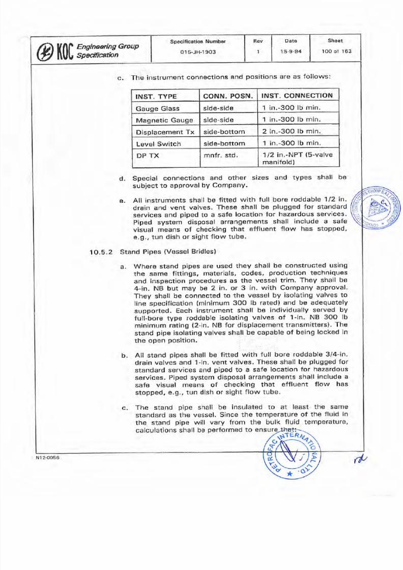
7/25/2019 015-JH-1903
http://slidepdf.com/reader/full/015-jh-1903 100/163
c
The
instrument
connections
and
positions
are as
follows:
1/2
in,-NPT
(5-valve
manifold)
mnfr. std,
P
TX
1 in.-3OO
lb min
ide-bottom
evel
Switch
2 in.-300
lb
rnin
ide bottom
isplacement
Tx
1 in.-300
lb
min,
ide-side
agnetic
Gauge
1
in.-3OO
lb min.
ide-side
auge
Glass
INST.
CONNECTION
ONN.
POSN.
NST.
TYPE
d.
Special
connectîons
and other
sizes
and types
shall
be
subject
to
approval
bY ComPanY.
e.
All
instruments
shall
be
fitted
with
full
bore
roddable
1/2
in.
drain
and
vent
valves. These
shall
be
plugged
for
standard
services
and
piped
to
a
safe
location
for
hazardous
services.
Piped
system
disposal
arrangements
shall
include a
safe
visual
rneans of checking
that
effluent
flow
has stopped,
e.g.,
tun
dish
or sight
flow
tube.
10.5.2
Stand
Pipes
(Vessel
Bridles)
Where
stand
pipes
are
used
they
shall be constructed
using
the
same
fittings,
materials,
codes,
production
techniques
and
inspection
procedures
as
the
vessel trim.
They shall
be
4-in.
NB
but
may
be
2 in.
or
3 in,
with Company
approval
They
shall
be
connected
to
the
vessel
by
isolating
valves to
line specification
(minimum
300
lb
rated)
and be
adequately
supported.
Each
¡nstrument
shall
be
individually
served
by
full-bore
type
roddable
isolating
valves
of
f
-in.
NB 30O
lb
minimum
rating
(2-in.
NB
for
displacement
transmitters).
The
stand
pipe
isolating
valves shall
be capable
of being
locked
in
the
open
position.
b.
All
stand
pipes
shall
be
fitted
with
full
bore roddable
3/4-in
drain
valves
and
f
-in,
vent valves.
These
shall
be
plugged
for
standard
services
and
piped
to
a
safe
location
for
hazardous
services.
Piped
system
disposal
arrangements shall
include a
safe
visual
means of checking
that
effluent
flow
has
stopped, e.9,,
tun
dish
or
sight flow tube.
c.
The stand
p¡pe
shall
be
insulated
to
at
least
the
same
standard
as
the
vessel.
Since
the
temperature of
the
fluid
in
the
stand
pipe
witl
vary from
the
bulk
fluid
temperature,
calculations
shall
be
performed
to ensu
a
@tí|f,rmx,GrouP
1
Rev
pecification
Number
015-JH-1903
Sheet
100 of
163
Date
15-9-94
N12-0056
(f
7/25/2019 015-JH-1903
http://slidepdf.com/reader/full/015-jh-1903 101/163
liquids
shall
be
compensated
w
supplied
wíth
the
¡nstruments.
Mechanical
integrity is
not affected
by
differential
expansion
between
the
nozzle centres.
The weight
of
the stand
pipe
and all the
attached
instruments
shall
also
be
taken
into
account.
2. Fluid density
changes
do
not
cause
meâsurement
errors
outside
acceptable
lirnits
for
the
application.
10.5.3
Materials and
Fabrication
a.
All
instrument
wetted
pressure
parts
shall
be
constructed
using
materials equal
to the
vessel
design
specifications,
with welding, heat treatment,
NDT, certification
and hydro-
testing
all conducted
to
the
same
standard
as
the
vessel.
b.
NACE,
impact test¡ng
and
any
other
special
Project or
service
requirements shall
be
noted
on
the
data sheets and
shall
be supplied.
c
Operating
parts
of the
instruments
shall be constructed
of
materials
suitable for the
service
with a
minimum
requirement
of
316 stainless steel.
d.
lf the
float
of
float-type
instruments
cannot
be
pressure
tested
at
the
vessel
test
pressure,
this
shall
be
clearly
labelled on the
outside
of
the
instrument,
Where the
measured
liquid
contains
particles
or
material
which
would
accumulate
in
the chamber
or
connecting
piping,
the
nozzle(s)
shall
be
purged
with
a compatible fluid,
The fluid shall be monitored
by
a
constant
flow
regulator and
alarm.
1O.5.4
Visual
Gauges
tGlass
and
Magnetic
Coupled
Types)
a.
General
Requirements
1.
All
fittings and
valves for
gauges
shall
be of steel unless
the service
requires
different
materials.
2.
All
gauges
shall
be stamped
with
the
maximum working
pressure
and
temperature.
3.
Gauges
on
vaporising service shall
be manufactured
with
oversized chambers.
4.
Expansion
and
contraction
of
gauges
used
on
hot
or
cold
1
e
¡th
sion loops
@ïr0|,, ;:;xx,Gr uP
Date
15-9-94
Rev
pecification Number
01s-JH-1903
Sheet
101 of
163
N
l
2-0056
t/t
7/25/2019 015-JH-1903
http://slidepdf.com/reader/full/015-jh-1903 102/163
5. ln
addition to the
line
class
valve,
all
gauges
shall
be
supplied
with
shutoff
valves
on the
top
and
bottorn
connections
and 112-in.
full-bore
roddable-type
drain and
vent
valves.
Shutoff
valves
shall
be
112-in.
NPT
nipple
connected
of
the
handwheel-operated
quick
action
offset screw-down
type,
with
bolted
bonnets
and
safety
velocity
ball
checks.
6.
For
special
services
using exotic materials,
the
shutoff
valve
may
be
replaced
w¡th
a
112-in. line
class
valve
or
omitted
completely subject
to
Company
approval.
b. Glass
Type Gauges
1.
Glass tube
gauges
shall not be
used.
2. Gauges on
coded
vessels
shall be
code stamped.
All
gauges
shall have
approval
by
Lloyds
or
an
equal body.
3. Gauges
shall comply
generally
with
the
requirements
of
BS
3463.
4.
Gauges
for
caustic
service
shall
be fitted
with
caustic
resistant
inserts.
5.
Gauges
for
cold
service shall
have frost
protection.
6.
Double-plate
and
reflex
gauges
shall
have
forged
steel
columns
and
toughened Borosilicate
glass.
Allowance
shall
be
made
to take
up expansion
without
undue
stress
on
the
instrument
or nozzles.
7. Transparent
gauges
shall
be
backlit
with
an illuminator
suitably certified
for
the
hazardous
area.
A
foot
switch
shall be supplied,
connected
to
the
electrical
system in
such a way
that
the
light
remains
on
for
an
adjustable
period
after
depression
of
the
switch.
The
specification
of
the
electrical items
shall be
in
accordance
with
the
Engineering
Group
Specification
entitled
Electrical
Design, lnstallation
and Testing
(Number
01S-pH-
19011.
8. Extended
gauge
glasses
shall
not
be of
more than four
sections
long.
c
Magnetic
Coupled
Gauges
1.
Two
types
are
acceptable:
Sheet
1O2
ot
163
Date
15-9-94
Rev
pecification
Number
01s-JH-1903
ØtÃ01,?-rynYx,GrauP
Nl 2-0056
7/25/2019 015-JH-1903
http://slidepdf.com/reader/full/015-jh-1903 103/163
a.
Parallel-tube
types having
a
density
balanced
float
in
a
parallel
chamber magnet¡cally
coupled
to
the
float
in
the
process
fluid.
b. Magnetic-indicator
types where
magnetised
flaps
or
balls
with
contrasting
paint
colour
on
each
side
roll
over
as
the
float
magnet
passes
them.
2.
The
chamber
mater¡al
shall
be
316
stainless
steel
unless
the
service
demands
a
higher
specification.
10.5.5 Displacer
lnstruments
a.
The
top
and
bottom
of
the
chamber
shall
be
full-sized
flanged
to enable withdrawal
of
the
disptacer
and cleaning.
b.
The
head
shall
be rotatable
on the flanges
to enable
orientation.
The
required
handing
shall
be
noted
on
the
data
sheet.
Electronic
transmitters
shatl
have
an
output
of
4-20
mA
24-VDC
supply
and
be
certified
in
accordance
with
hazardous
area
and
execution
code
stated in
the
Engin
Group
Specificatio
n
entitled
lnstrument
Engineering
Basic
Data
(Number
01s-JH-1901).
An output indicator
shall
be
provided.
Pneumatic
instruments
shall have
an output
of
O.Z-1.O
barg
(3
to
15
psig)
with
a
suppty
pressure
of
1.4
barg
(20
psig).
An
output
gauge
shall
be
provided.
f
. Displacer
instruments
shall
be
glandless.
g.
Standard
materials
are
1
,
Displacer:
316
staínless steel.
2.
Torque
tube:
lnconel.
h. lnternal
displacers
mây
be
used
where
an
external
arrangement
is
not
possible (e.9.,
sumps).
ln
this
case,
facilitíes
shall
be
provided
to
allow testing
and
routine
maintenance.
All
such
displacers
shall
be
shielded
and
guided,
and
a
means
shall
be
provided
to reta¡n
and
recover
dislodged
displacers.
The
mounting
flange
for
top-mounted
instruments
is
4
in.
unless
a larger
size
is
required.
c
d
e
Sheet
103
of
163
Datê
15-9-94
Rev
pecification
Number
015.JH-1903
Øïr0|.,?,t Y:x^*ouP
cr
N't
2-0056
ril
7/25/2019 015-JH-1903
http://slidepdf.com/reader/full/015-jh-1903 104/163
7/25/2019 015-JH-1903
http://slidepdf.com/reader/full/015-jh-1903 105/163
7/25/2019 015-JH-1903
http://slidepdf.com/reader/full/015-jh-1903 106/163
7/25/2019 015-JH-1903
http://slidepdf.com/reader/full/015-jh-1903 107/163
the
minimum additional
requirements
related
to
level
instruments
only and
shall
not
¡n
any
way
replace
or
reduce
the
general
OA/OC
requirements.
b.
The
test
and
inspection
plan
shall
include
the
following
items
in
addition
to those
found
necessary
by
the
Approved
Manufacturer
to ensure
the
quality
of the
product:
A check of
all
materials
of
construct¡on
by
cross-
comparing the
goods,
the
material
test
certificates
and
the
data
sheets
and
Drawings.
A
check of
the
dimensions
of
the
finished
instruments
against
the
Drawings supplied
for
the
Contract
and
approved
by
the
Company.
3.
A
check
of
the
instrument
and all accessories
in
accordance
with
this
specification
and
the
data sheets
and
Drawings.
4.
Full
testing
of the
instrument
in
accordance
this
specification,
Approved
Manufacturer's
additional
OA/OC
procedures
and
the
approved
Test
and
lnspection
Plan.
5.
A
check
on
the
nameplate
data
¡n
accordance
wíth
this
specification
and
the
data sheets and
Drawings.
6.
A
check
on
the
painting
and
protection
and
general
suitability
for
the
environment.
7. A
check
on
the
tagging
in
accordance
with
this
specification
and the data
sheets.
1
2
10.7.2
Testing
ct
The
pressure enclosures
shall
be
hydrostatically
tested
before
assembly
at
1.5 tímes the
rating
of
the
flanges.
b.
The
instrument
shall
be calibrated
with
a
fluid
having
the
same
properties
as
the
process
fluid.
The
lnstrument
shal¡
be
pressure
tested
as an
assembly at
no
greater
than 1.5
times
the
rating
of
the
flanges,
but
this
figure
shall
be
reduced
if there
is
a
design
restriction
on
pressure
on any
component.
lf
such
restrictíons exist, this
fact
shall
be clearly
marked
on the
instrument
in
English
and
Arabic
languages.
c
Rev
pecification
Number
01s-JH-1
903
@|ffi'åomn **
Sheet
107
of
163
Date
1
5-9-94
Nt
2-OOs6
fþ

7/25/2019 015-JH-1903
http://slidepdf.com/reader/full/015-jh-1903 108/163
1O.7.3
Documentation
All
the
certificat¡on
for
each
instrument
or
group
of
instruments
shall þe
collated
in
a Data
Book which
shall be
available at
f¡nal
inspection.
The book shall
include as a
minimum:
a. Completed
test
and
inspection
plan.
b,
Material
certif¡cates
and component
certifícates.
c. NDT certificates.
d.
Weld
procedures
and
qualifications.
e. Pressure
test
certificates.
f.
Test
and
calibration
certif¡cates.
g.
Hazardous
area certificates.
h.
As-built
Drawings
as
necessary.
1O.8
Nameplate
Data
1O.8.1
General
information
for
production
of
the nameplate
data
is
given
in
section
4.7 oÍ
this
specification.
1O.8.2
For level
instruments
the following
additional information
is
required:
a.
Body
material
.
b.
lnternals
mater¡al.
c.
Rating
of
inlet
and
outlet
flange .
d.
Test
pressure
of
complete instrument.
11.O TANK
METERING
11.1
Aoolicable
Slandards
API
Manual
of
Petroleum
Measurement
Standards
-
Chapter
3
-
Tank
Gauging
11.2
Scope of
Tank
Metering Section
ents on
nk
and
storage
1.2.1
This
sect¡on
details
process
measurem
vessels
where
the
selection
criteria
for stated in the
@Ktl, ;:;xx,GrauP
Date
15-9-94
ßev
pecification
Number
015-JH-1903
Sheet
108
of
163
N1 2-0056
rþ
7/25/2019 015-JH-1903
http://slidepdf.com/reader/full/015-jh-1903 109/163
level
instruments
section
of
this
specification
cannot
generafly
be applíed due
to
span resrrictions.
This
specification
applies
to
storage
tanks
only. For
process
vessels
on
which
conventional
process
level
variables
are
requíred
to
be
measured,
for
the
purposes
of local
indicatíon
or
remote
signal
transmissiofl,
the
requirements
are
covered
by
section
1O.O
of
this
specification,
Level
Measurement,
11.3
Tank
Metering.lnsfI-uments
Tvoe
and
Sete,ction
11.3.1
Use
of
Conventional
lnstruments
where
conventional instruments
are
applied
to
tank
level
measurements,
e.9.,
level
switches,
dírect
Dp
measurement,
displacer instrurnents,
etc.,
the
requirements
of
section
lo.o
of
this
specification
shall
be
followed.
Dedicated
level
switches
shall
be
used
for
the
high
and
low
tr¡p
detection.
They
shall
be
displacer
type for
low-level
detection
and
float
type
for
high
level.
11.3.2 Measurement
of
Large
Spans
The
method
of measuring
the
full
span
of
the
tank shall
be
indicated
on
the
P&lD
íssued
for
the
project,
or
if
not indicated
shall
be
agreed
to
wíth the
company
during design
definition.
The
selection
shall
be from
the following
instrument
types:
a.
lnferred
level
measurement,
using
Dp
measurernent
by
a
Dp
transmítter.
The
local
readout
can
be
a
direct
reflection
of
the
calíbration
of
the
transmitter,
or
a
re-transmitted
signal
from
the
DCS
(including
any
specified
corrections
appliedl.
b.
Float-operated
mechanically
linked
indicator
with
position
transmifter.
servo-motor-operated
float or
displacer-type
surface-seeking
systems.
These
shall
be
specified
with
micro-processor_
based
calculation
modules.
d. Badar-type
tank
level
gauges.
e servo-motor
operated
surface-seeking
capacitive
tank
level
gauges.
t.
Sonic
and
ultrasonic
tank
level
gauges
g.
lnductive
tank
level
gauges.
11.2.2
c
Sheet
109
ol
'163
DatÊ
15-9-94
Rev
pecification
Number
01
5-JH-1
903
@r|;ß:*m,Group
N t 2-0056
,1,
7/25/2019 015-JH-1903
http://slidepdf.com/reader/full/015-jh-1903 110/163
7/25/2019 015-JH-1903
http://slidepdf.com/reader/full/015-jh-1903 111/163
2.
Liquid volume:
cubic
metres
(m3).
3.
Mass:
kilogram
(kg).
4.
Density:
kilogram
per
cubic
metre
(kg/m3).
Facilitíes
shall
be installed
on
the
tank
adjacent
to
the
b.
For
DP-based
systems
on
tanks
with
liquid
interface
control,
the
calibrated
range shall
commence above
the
highest
interface
level.
c.
Level
coordination
sketches
showing
all
pertinent
information
shall
be
produced
by
the
Contractor
for
all
applications.
These
shall
be
approved
by
the Company
and
verified
by
the
Approved
Manufacturer
before
order
placement.
d, scales
shall
be
as follows
unless requested
otherw¡se
by
the
Company:
1.
Local
and
remote
level indication:
O-100 .
d
gauging
system
to
enable
manual
gauging
by dip
rod.
complete
system
shall
be
field
calibrated in
accordance
with
all recommendations
in
the
Apl
code
previously
noted.
11.4.2
Requiremenrs
for
Hydrostatic Tank Gauging
System
The
hydrostatic
tank
gauging
(HTG)
system
shall be
ranged
in
accordance
with
the
API
Manual
of
petroleum
Measurement.
Chapter
3.
1
1.4.3
Temperature
Measurement
The
temperature
measurement
shall
be
by
use
of
an
RTÐ. The
RTD
shall
be mounted
in
a
thermowell
mounted
adjacent
to
the
lower
transmitter
tapping
and
penetrating
at
teast
I
m
into
the
process
fluid. The
readout shall
be
ranged
to
cover
frorn
zero
to
the
maximum
possible
process
temperature,
allowing
for
any
increase
due
to ambient
effects.
11.4.4 Oil/Water
lnterface
Measurement
The
oiliwater
interface
detection
shall
be by
use of
an
externally
mounted
displacement
transmitter,
a
capacitance
probe,
or by
another
company-approved
method.
The
range
of
the instrument
shall cover
all
possible
movement
of
the
interface
level,
up to
and
including
the
upper
process
fluid
outlet
level.
Sheet
111
ol
163
Dato
15-9-94
|
Rev
pecification
Number
015-JH-1903
@W,gm:x,*oup
N
1
2-005ô
rr'
7/25/2019 015-JH-1903
http://slidepdf.com/reader/full/015-jh-1903 112/163
7/25/2019 015-JH-1903
http://slidepdf.com/reader/full/015-jh-1903 113/163
for the
process
conditions and
equipment
loads.
Flange finish
and
gaskets
shall be
in accordance
w¡th the tank
specification.
1
1.6.3
The
system shall be
installed
in
accordance
with
the
requirements
of
the
Engineering Group
Specification entitled
lnstrument
¡nstallation
(Number
01s-JH-1908) and
any
applicable
special notes
contained
in
the
Level
Measuremerìt
section
1O.0
of this specification. All
instruments
shall
be
provided
with isolation
valves
to enable removal for maintenance
without
tank drainage.
1
1.6.4
The
measurement
sensors shall
be
placed
clear
of all
incoming
and outgoing
process
flow
penetrations,
mixers
or distributors
and
any
possible eddy
currents
in
the fluid
etc.
1
1.6.5 The Contractor
shall
provide
at each tank a
telephone
jack
connection for
a
portable
These
shall connect
¡nto
the control
room
system.
11.7
PerfoJr.nance
Requirements
11.7.1
Ouality Control
(OC)
OC
shall be as
detailed
in the
Contract. This section
states
the
minimum
additional
requirements
related to
tank
gauging
systems
only
and
shall
not in
any
way
replace
or
reduce
the
general
OA/OC
requirernents.
b.
The
test
and inspection
plan
shall include
the
followíng items
in
addition to
those found
necessary by the Approved
Manufacturer
to
ensure
the
quality
of the
product:
A
check
of
all
materials
of
construction
by
cross-
comparing
the
goods,
the
rnaterial
test certificates
and
the
data
sheets
and
Drawings.
2.
A
check
of the dimensíons
of the
fÍnished
instruments
against the Drawings
supplíed
for
the
Contract and
approved by
the
Company.
3.
A
check
of
the
instrument
and
all
accessories
in
accordance with
this specification
and the data
sheets
and
Drawings.
junction
box
with
a
telephone handset.
telephone
exchanç
Æ
l[e,I
\\'ur.\
\\ú'.ôr,
X
a
1
4.
Full
testíng
specification,
of the
instrument in
accordance
this
Approved
Manufactu
additional
OA/OC
procedures
and
the
appro
plan.
pection
Sheet
113of163
Dats
15-9-94
Revpecification
Number
015-JH-1903
Ør|f.,i;y*ffi, -*
rt
12-0056
7/25/2019 015-JH-1903
http://slidepdf.com/reader/full/015-jh-1903 114/163
7/25/2019 015-JH-1903
http://slidepdf.com/reader/full/015-jh-1903 115/163
7/25/2019 015-JH-1903
http://slidepdf.com/reader/full/015-jh-1903 116/163
1. Two
term,
proportional
and
integral
(integral
normally
usedl.
3.
External
auto-manual
station
with bumpless transfer
facility,
4.
Reset
wind-up
prevention.
b.
Combined
transmitter/controller
systems
may
be
offered
for
company
approvãl
when
the
serv¡ce
conditions
are
suitable
for
standard
capsules.
12.2.3
Local
Flow
Controllers
a.
Flow
controllers
shall be
specified
as
follows:
1.
Two term,
proportional and
integral.
2.
Proportionalband
O
to
5OO '
3.
External
auto-manual
station
with bumpless
transfer
facilitY.
4.
Reset wind-uP
Prevention.
'12.2.4
Local
Level
Controllers
a.
Level
controllers
shall
be
specified
as
follows:
not
2.
Proportional
band
0-100
3.
External
auto-manual
station
with
bumpless
transfer
facility.
4.
Reset
wind-up
prevention
b.
Combined
transm¡tter/controller
systems may be offered for
Company
approval
when
the
service
such as
tank heating
upto
300'
C
1572'F)
range.
12.2.5
LocalTemperature
Controllers
a.
Temperature
controllers
shall
be
specified
as follows:
1.
Three
term,
proportional,
integral
and
derivative.
2.
Proportional
band
0 to 250
@ïr0lY,'*w,GrouP
1
Rev
pecilication
Number
01s-JH.1903
Sheet
l16of
163
Dâte
15-9-94
N12-0056
rl,
7/25/2019 015-JH-1903
http://slidepdf.com/reader/full/015-jh-1903 117/163
1
3,
External
auto-manual
facility.
station
with
bumpless
transfer
4,
Reset
wind-up
prevention
b.
Combined
transmitter/controlfers
of
the liquid
or
gas
filled
type
may
be
offered
tor
Company
approval
for
símple
services
such
as
tank
heating
up
to
3o0'c
l572oFl
range.
12.3
Sizing
qnd
Ranoina Reouirements
12.3.1 The
calibrated
range
of
the
controller shall
be the
same
as
the
range
selected for
the
associated
Transmitter.
The
span
shall
be
selected
so
that the
range accounts
for
at
least
50%
of
the
span.
12.3.2
The
scale shall
be
graduated
to
the same
characteristic
as
transmitter
output
unless
external signal
conditioners
indicated
on the
p&lD
.
12.4
Design
and
Construction
12.4.1
General
a.
Local
controllers
shall
be
of
large case design
with
lockable
front.
They
shall be mounted
on
a
2-in.
instrument
stand
or
rear
flange
mounted.
b.
The
movement
shall
be
of
nozzle
and flapper
mot¡on
or
force-
balance
type,
integral
air supply
and
output
gauges
shall
be
f¡tted.
c. lndicating
scales
shall
be
white
with
black
numerals.
units
and
multiplyíng
factors
shall
be
marked
d.
Auto-manual
switch
shall
be
external.
set-point
adjustment
may
be
external
or
internal according
to
the
applícation.
Auto-manual
switch
may
be
substituted
for
remote/balance/auto/manual
when indicated
on
the
p&lD.
An
indÍcator
shall
be
provided
for
the
remote
signal.
e, The
wetted
parts
shall
be
316 stainless
steel
(preferred)
or
bronze.
f
The
signal
ourput
shail
be
O.2
to
1.0
barg
(3
to
15
psíg).
The
action
shall
be
reversible.
The
supply
air
pressure
shall
be 1.4 barg
(20
psig,.
g.
Air
connections shall be
1/4-in,
NpT.
Sheet
117of
163
Dâ1e
15-9-94
Rev
pecification
Number
015-JH-1903
Øl0liJ;gnYx,Gr'uP
:
Nr
2-0056
rp
7/25/2019 015-JH-1903
http://slidepdf.com/reader/full/015-jh-1903 118/163
7/25/2019 015-JH-1903
http://slidepdf.com/reader/full/015-jh-1903 119/163
7/25/2019 015-JH-1903
http://slidepdf.com/reader/full/015-jh-1903 120/163
7/25/2019 015-JH-1903
http://slidepdf.com/reader/full/015-jh-1903 121/163
13.4.3
The
sensor casing
shall be stainless steel.
Local
brackets
shall
be
stainless steel.
13.4,4
Connecting
leads
shall be fully
protected,
as short
as
possible
and terminated
in
an approved certified enclosure.
13.4.5
The
sensors
shall
be immune from radio frequency interference.
13.5
lnstallation
Notes
13.5.1
Detectors
shall
be
installed in
accessible
positions
with
sufficient
protection
to enable
freedom from
damage during operation
and
maintenance.
13.5.2
They
shall
not
be
placed
where
debris
from ruptured
couplings,
shear
pins
etc. can be expected
to impinge.
13.5.3
The
units shall
be
factory
installed
and tested
in
conjunction
with
the
equipment
performance
tests
and
connected
to the
specif
ied
a
mpl
if
ier/inte
grator.
13.6
Performance
Reouirements
13.6.1 Ouality
Control
(OCl
OC
shall be as
detailed
in the
Contract. This section
states
the
mÍnimum
additional
requirements
related
to
speed
measurement
instruments
only
and
shall
not in
any
way
replace
or
reduce
the
general
OA/OC
requirements.
b. The test and
inspection
plan
shall
include
the
following
items
in
addition to those
found
necessary by the Approved
Manufacturer
to
ensure
the
quality
of the
product:
A
check
of
the
instrument
and
all
accessories
in
accordance with
this
specification and the data
sheets
and Drawings.
2. Full
works
calibration
and
issue
of
test and
calibration
certificate.
3.
A
check
on
the nameplate data
in accordance
with
this
specification
and
the
data
sheets
and
Drawings.
4.
A
check
on
the
painting
and
protection
and
general
su¡tability
for
the
environment.
5. A
check
on the tagging
in
specification
and
the
data
sheets.
accordance with
this
a
1
@tí0[31,:x::x^Group
Sheet
12 l
of
163
Date
15-9-94
Rev
pecification
Number
01s-JH-1903
, r
N I
2-0056
7/25/2019 015-JH-1903
http://slidepdf.com/reader/full/015-jh-1903 122/163
13.6.2
Documentation
The following
data
shall
be
avaitable
at
final
inspection:
a.
Completed
Test
and
lnspection
plan.
b. lnstrument
test and
calibration
certíficate.
c.
Hazardous
area
certificates.
13.7
Nameplalp_Da.Îa
General information
for
production
of
the nameplate
data
is
given
in
section
4.7
ot this
specification.
14.0 VIBRATION
SENSING
14.1
Scope
of
Vibration
Sensing
Sectign
This section
covers
the
measurement
of
shaft vibration
sensing
equipment
to
be
installed
at
the
Facility
in
Kuwait.
14.2
Vibration
Sensino
lnstruments
Tvpe
and..Selection
14.2.1
Standard
System
Degrees
of
vibration
shall
be
measured
by
field-mounted
eddy
cufrent
transducers
or
piezo-electric
accelerometers
mounted
at
the
detection
points
on
the X
and
y
axis
of
the
rotating
shaft.
A
contro
room-mounted
integrator,
scaled in
accordance
with
the
limitíng
conditions
applicable
to the
specific
equipment
shall
transmit
the
vibration
rneasurement
as
a 4-2o
mA signal
to
the
Dcs,
ESD
or
interlock
system.
Adjustable
contact
alaim
outputs
shall
also
be available.
14.2.2
Alternative
Systems
other
types
of
system may be
offered
for
company
approval
if
the system
offers
an
equal
standard
of
integrity
and
relíability.
14.2.3
lntegration
with Monitoring
Systems
where
vibration
measurement
is
specified
as
part
of
an
overall
equipment
monitoring
system. The
contractor
shall
ensure
that
the selected
system
is
cornpatible
with
the
equipment
installation
and signal
monitoring
requirements.
Sheet
122
o1
163
Date
15-9-94
Rev
peclfication
Number
01s-JH-1
903
@rif,Ym,Grvup
rr'
l2-0056
7/25/2019 015-JH-1903
http://slidepdf.com/reader/full/015-jh-1903 123/163
14.3
Sizinq-and
Ban
ging
Requirements
The display
scale
shall
be
calculated
so
that
the
maximum
predicted
running
vibration
is
between
600/o
and
80%
of
full
scale'
Gonstfucfion
Reouirements
14.4.1
Vibration
sensors
shall
be
of
robust
construction
suitable
for
service
on
the
specific
type
of
rotating equipment,
taking
into
account
temperature,
lubricants etc.
14.4.2
DupliCate
sensors,
or Complete
Systems
as
necessary,
shall
be
supplied,
allowing
one
unit
to
be serviced
while
the
other
is
on-
line.
14.4.9
The
sensor
casing
and
extension
shall
be
stainless
steel.
Local
brackets
shall
be
sta¡nless
steel.
14.4
14.4.4
Connecting
leads shall
be
fully
protected,
as
short
as
possib
and
terminated
in
an
approved
certifìed
enclosure.
14.4.5
The
sensors
shatl
be
immune
from
radio
frequency
interference'
14.5
lnstallation
NoteF-
14.S.1
Detectors
shall be
installed
in
accessible pos¡tions
with
sufficient
protect¡on
to
enable
freedom from
damage
during
operation
and
maintenance.
14.5.2
The sensors
shall
be
positioned
so that
electromagnetic
fields
close
to the
equipment
do
not affect
the
reading.
14.5.3
They
shall
not be
placed
where
debris
from
ruptured
couplings,
shear
pins
etc.
can
be
expected to
impinge.
14,5,4
The
units
shall
be
factory
installed
and tested
in
conjunction
with
the
equipment
performance
tests
and
connected
to
the
specified
amplifierlinte
grator.
14.6
Performance
Requirements
14.6.1
Ouality
Control
(OC)
OC
shall
be as
detailed
in
the
Contract.
This
section states
the
minimum additional
requirements
related
to
vibration-
senstng
instruments
only
and
shall
not
in
any
way
replace or
reduce
the
genera¡
OA/OC
requirements.
a
@lffi
7,y#iJH,GrouP
Specification
Number
015-JH-1903
Date
15-9-94
Rev
Sheet
123 of
163
Nl 2-0056
rf
7/25/2019 015-JH-1903
http://slidepdf.com/reader/full/015-jh-1903 124/163
A
check
on
the
tagging
in
accordance
specification and
the
data
sheets.
b.
The
test
and inspection
plan
shall include
the
following
items
in
addition
to
those found
necessary
by the
Approved
Manufacturer
to
ensure
the
quality
of the
product:
A
check of
the
instrument and
all
accessories
in
accordance
with
this
specification and
the
data
sheets
and
Drawings.
2. Full
works
calibration
and issue of
test
and
calibration
cert¡f¡cate.
3.
A
check
on
the
nameplate
data in
accordance
with
this
specification
and
the
data
sheets
and
Drawings.
4,
A
check
on
the
paintÍng
and
protection
and
general
suitability
for
the
environment.
1
5
with
th
14.6.2
Documentation
The
following
data
shall
be
available at final inspection:
a.
Completed Test
and
lnspection Plan.
b.
lnstrument
test and
calibration certificate,
c. Hazardous
area
certificates.
14.7 Nameplate Daia
General
information
for
productiòn
of
the
nameplate
data
is
given
in
section
4.7 af
this
specification.
15.O SOLENOID
VALVES
15.1
Apolicable
Standards
Bs
2757
Method for
Determining
the
Thermal
classification
of
Electrical
lnsulation
15.2
$Sop.e
of
Solenoid
Valve
Sgction
This section
details
the
requirements
for
the
application
of solenoid valves
in the
plant
when
used
as
part
of
the
process
control
or
shutdown
system.
Sheet
124
of
163
Date
15-9-94
Rev
pecification
Number
01s-JH-1903
@r|Jv,J;: nyx,Group
N12-0056
,'r
7/25/2019 015-JH-1903
http://slidepdf.com/reader/full/015-jh-1903 125/163
7/25/2019 015-JH-1903
http://slidepdf.com/reader/full/015-jh-1903 126/163
15.3.7
Solenoid
Valves for Venting
Service
For venting
both
sides
of
a
double-acting actuator
(e.9.,
to
enable
manual
override),
two
three-port
valves
shall
be
used.
15.4 Sizing and
Ranqing
Reouirements
15.4.1
Sizing
for
Speed
of
Operation
The minimum
solenoid
valve
size used
shall
have
1/4-in.
NPT
connections
and
a 6-mm
(1/4-in.)
orifice. The
Contractor
shall
not
assume that
this
is
adequate
to
achieve
the
required
speed
of
operation
without
verification
of each case
taking
into
account
the
completed installation
of
actuated
valve/connect¡ng
tube/solenoid
valve/exhaust
arrangement.
15.4,2
Sizing for Process
Service
ln
cases
where
the
Company
has
approved
the use of a
sole
valve for
direct
process
duty,
each
application
shall
be
s
against the
operating
conditions.
15,5
Construction
Requirements
15.5.1
General
Solenoid
vafves
shall be
direct-acting,
spring-return
type and
shall
be
robustly
constructed
for
heavy
industrial
use.
The coil
and
spring
shall be selected to
provide
ample operational
power
to
position
the
valve
stem correctly under all
conceivable
service
conditions.
An
external
earth stud
shall be
provided.
15.5.2
Design
Rating
The design
pressures
shall be as
follows
(minimum
requirements):
{to
be according
to service requirements
but
not less
than
1.5 x
process
design figure)
Processes
Service
(to
be according
to
individual
requirements
but
not
less than
the
blocked-in
pump
head)
Hydraulic
Service
8.5
barg
(125
psigl
12.0
barg
{175
psig)
Pneumatic
Service
Operating
Mechanical
-@
Shêet
126
of
163
Date
15-9-94
Rev
pecification
Number
01
s-JH-1
903
@ïr0|., ;gxm^GrouP
N1
2-0056
7/25/2019 015-JH-1903
http://slidepdf.com/reader/full/015-jh-1903 127/163
15.5.3
Coil
Rating
coils
shall
be
rated
for
continuous
operat¡on
when
connected
to
the efectrícal
suppty
stated in
the
Engineering
Group
specification
entitled
lnstrument
Engineering
Basic
Data
(Number
01S-JH-19011.
The
temperature
must
not
rise
ro
more
than
70'c
(158 F),
(or
the coil
service
rating
if lower)
when
used
at
the
ambient
conditions
prevalent
at
the
Facility
and with
the
sun shielding
and heat
dissipation/cooling
arrangements
provided
by the
Contractor.
15.5.4
Coil
lnsulation
Coil
insulation shall
be
Class
A
to
BS
27SZ
(minimum),
and
a
surge
suppression
device
shall
be
fítted
within
the
terminal
enclosure.
15,5.5
Terminations
lntegral
terminals
shall
be
provided
for
the
termination
of
cabling.
Flying
leads
extending
from
the
coil
enclosure
are
not
acceptable.
15.5.6
Electrical
Entry
The
electrical
entry shall
be
lso
metric
threaded
to
M2o
x
1.5
mm.
15.5.7
Body
Materials
Pneumatic
solenoid
valves
shall
be constructed
of brass
or
stainless
steel
body,
stainless
steel
trim
and
cast iron
enclosure.
Aluminium
enclosures
are
acceptable
only
if fully
epoxy
painted.
b.
All
solenoid
valves
shall
be
stainless
steel in
cases
where
Hrs
is
present
in
any
part
of
the
process
in
sufficíent
quantity
to
warrant
the
need
for
materials
to
be
selected
and
manufactured
in
accordance
with
the
NACE
code
MRo175.
This
is
to
enable
the
valve
bodies
to
resist
the
Hrs
that will
be
present
in
the
atmosphere.
c. For
process
servíce,
the
body
and
trim material
shall
be
suitable for
the
process
fluid
and
design
conditions,
with
316
stainless
steel
as
a
minimum
requirement.
d. The
selection
of
seal
material
shall
be
pproved
Manufacturer's
recommendation
for
and
environmental conditions
c,
Sheet
127
of
163
Date
15-9-94
Rev
pecification
Number
01
s-JH-
1
903
@10|.,,;:m:x,Gr.up
N
1 2-0056
7/25/2019 015-JH-1903
http://slidepdf.com/reader/full/015-jh-1903 128/163
7/25/2019 015-JH-1903
http://slidepdf.com/reader/full/015-jh-1903 129/163
I
3. A
check
of the
instrument
and
all
accessories
in
accordance
wìth this
specification and
the
data
sheets
and
Drawings.
4. A
check
on
the nameplate
data
in
accordance
with
this
specification
and
the data sheets
and
Drawings,
5. A
check on
the
painting
and
protection
and
general
suitability for
the
environment.
6.
A
check
on
rhe
tagging
in
accordance
with
this
specification
and
the data
sheets.
15.7.2
Testing
The
solenoid
valves
shall
be
tested
during
accordance
with
Approved
Manufacturer's
system.
manufacture
in
quality
control
15,7.3
Documentation
All
the cert¡f¡cation for
each
instrument
or
group
of
instrumen
shall
be collated in
a
Data
Book
which
shall
be
available
at fina
inspection.
The
book
shall
include
as
a
minimum:
a.
Completed
test
and
inspection
plan.
b.
Certificate
of
works
test
and
conformity
c.
Hazardous
area
certificates.
15.8
Namenlate
Data
General
information
for
production
of
the
nameplate
data
is
given
in
section
4.7
of
this
specification.
16.0
SIGNAL
CONVERTORS
16.1
ScoBe
of
Signal Gonverter Section
This section
details
the
requirements
of
signal
convertors
for use
in
signal
transduction
and
manipulation
of
pneumatic
and
electronic
signals used
in
instrument control
loops.
16.2 Siqnal Converters.Tyge
and
Selectig_[
16.2.1
Current
to Pneumatic
Conversion
(l/P)
Conversion
of
a
control
room
4-20
mA a
0.2
to
Sheet
129
of 163
Date
1
5-9-94
Rev
pecification
Number
016-JH-1903
@101,# m:x,GrouP
N12-0056
7/25/2019 015-JH-1903
http://slidepdf.com/reader/full/015-jh-1903 130/163*
o
ú
J}
1.0
barg
(3
to
15
psig)
pneumatic
signal
shall
normatly
be
by
use
of
a 2-wire
loop powered l/P
convertor.
For
control
valve
service
in
non-vibrating
applications,
and if
approved
by
the
Company,
EIP
positioners
(where
the signal conversion
is
an integral
part
of
the valve
positioner)
may
be
used.
16.2.2
Pneumatic
to Current
Convertors
(P/l)
Conversion
of a
field
pneumatic
signal
for
transmission
to
the
control
roorn
as
an
electronic
signal shall
be
by
use
of
a
2-wire
loop
powered
P/l
convertor.
1
6.2.3
Miscellaneous
Convertors
and
Conditíoners
Fiefd-mounted
devíces
shall be
used
where
depícted
on the
p&lD
for
signal
processing
such as square
root
extraction,
high
and
low
selection, multiplying
and
delay
services.
16.3
Sizíng
Retuirements
16.3.1
The
pneumatic
output flow
rate
from
convertors
shall
checked
against
the
maximum
air
requirement
of
the
Pneumatic
relays
and boosters
shall
be
used
as
necess
ensure
an
adequate
supply
of air.
ary
16.3.2
Current
to
pressure
{l/P}
and
pressure
to
current (p/l}
convertors
shall
be
field
adjustable
and
ranged
so that 4-2o
mA corresponds
to
0.2 to
1.0
barg
(3
to
15
psig),
unless
required
otherw¡se
by
the
service.
16.3.3
split
ranges
shall
be accomplished
by
using
two
outputs
from
the
DCS, each
scaled at
O-100
o/o.
ln
this
case,
each
valve will
have
an
individual
l/P
convertor
scaled
0.2
to 1.O
barg
{3
to
lb
Psig).
16.3.4
where
split
range
control
using one
electroníc
output
is requ¡red
eg.
0.2
to
O.6
barg
(3
ro
9
psig)
and
O.6
to
1.0
barg
(9
ro
15
Þsig)
signals
to
each valve respectively,
one
l/P
convertor
shall
be used
and
the
split
ranging
shall
be
carried
out
at
the
positioners.
16.3.5
Other
ranges
Company.
may
be
specified
with
the
agreement
of
the
16.4
Construction
Hequiremen_tg
16,4,1
llP
Convertors
Sheet
1
30
of 163
Datg
15-9-94
Rev
pecification Nurnber
015-JH-1903
Ø10|,,?,: mx^Group
Nl2-OO56
rl,
7/25/2019 015-JH-1903
http://slidepdf.com/reader/full/015-jh-1903 131/163
7/25/2019 015-JH-1903
http://slidepdf.com/reader/full/015-jh-1903 132/163
protective
box,
or
mounted
on
a
substant¡al
plate
and
a
cover
provided.
16,5.5 Sun
shielding
is
required
for
all convertors
16.6 Performance
Requirements
16.6.1 Ouality Control
(OC)
OC shall
be as detailed
in
the
Contracl.
This
section
states
the minimum additional
requirements
related
to signal
convertors only
and
shall
not
in
any
way replace
or
reduce
the
general
OA/OC requ¡rements.
b.
The
test
and
inspecl¡on
plan
shall
include
the
following
items
in
addition
to
those found
necessary
by the
Approved
Manufaclurer to
ensure
the
quality
of
the
product:
A
check
of
the
dimensions
of the finished
items
against
the
Drawings
supplied
for the
Contract
and
approved by
the Company.
2. A
check
of
the
equipment
and all
accessories
in
accordance
with
this specification
and
the
data
sheets
and
Drawings.
3.
Functional
test¡ng
of
instruments
in
accordance
with
this
specifícation,
Approved
Manufacturer s
additional
OA/OC
procedures
and
the
approved
test and
inspection
plan.
4.
A check on
the nameplate
data
in
accordance
with
this
specification and
the
data
sheets and Drawings.
5. A
check
on
the
painting
and
protection
and
general
suitabil¡ty
for
the environment.
6. A
check
on
the
tagging
ín
accordance
with
this
specification
and
the data
sheets.
16.6.2
Testing
lnstruments
shall
be
function
tested and calibrated.
16.6.3
Documentation
All
the
certification
for
each
instrument
or
group
of
instruments
shall
be
collated
in
a
Data Book wh
vailable
at
final
inspection.
ïhe
book shall include
a
1
6
Sheet
132
of
163
Date
1
5-9-94
l
Rev
pecification
Number
01s-JH-1903
@ïr0l ,Jfm,GrouP
:.
1:
r
I
Í
I
l
;
4
rL
d
N12-0056
,þ
7/25/2019 015-JH-1903
http://slidepdf.com/reader/full/015-jh-1903 133/163
a.
Completed
Test
and
lnspection Plan
b.
Hazardous
area
certificates
16.7 Nameolate Data
General
informatíon
for
production
of
the
nameplate
data
is
given
in
the
section 4,7 of
this
specification.
17.O
POSTT|ON
SWTTCHES
17.1
Scooe
of
Positíon
Switches Sectiqn
17
.1.1
This
section details
the
des¡gn
and
applicatíon
of
all
switches
installed
to
detect
the
limit
or
intermediate
position
of
valve
stems,
dampers,
safety
devices or
other
items
requiring
an
electrical
transmission
of a
fixed
position.
This
specifícation
shail
be
applicable to
switches
on
all
equipment
and
packages
to
be
installed
at the
Facility
in
Kuwait.
17.1.2 This
section does
not
detail
position
transm¡tters
used
for
cont¡nuous
feedback
of
the
position
of
a moving
part.
17.2
Position Switches Type
and
Selection
17.2.1
Switches
shall be of the
inductive proximity
type,
communicatÍng
with
an
ls
amplifier mounted
in
the
main
control
block
auxiliary room.
The amplifier
shall
give
volt-free
conract
outputs
1o
the DCS
and
ESD
equipment
as
necessary.
17.2.2 Conventional
contact-type
mechanical
action
lîmit
switches
shall
only
be
used
in
specific
applications when
approved
by
the
Company,
When
used,
they
shall
be
in
mechanical
fail-safe
mode,
i.e.,
the
spring
act¡on
shall
push
the
follower
toward
the
actuatíon
point
(inverse
cam
or
hole
etc.),
so
that a stuck
switch
cannot
be
interpreted
as
a safe
position,
such
switches
shall
use
environmentally sealed
switch
contacts
of
noble metal
suitable
for
low-energy
signals.
17.2.3 Proximíty
switches
shall
be
purchased
as
sets
ready
mounted
and
terminated in
a
sealed
enclosure
containing
the
switch
adjustment
and
actuation
system, The
only
exposed
part
shall
be
the
actuation
shaft
emerging
from a sealing gland
at
the
rear
of
the
box.
This
shall be
driven
by
the
moving part
which
is
to be
posit¡on
detected.
17.2.4
External
proximity
switches
may
be
restrictions
preclude
the
use of
enclosed
used
when
space
h
approval
from
the
Company,
and
provided
that
the
ted in
a
Shaet
133
of
163
Date
t5-9-94
Rev
pacification
Number
01
5-JH-1903
@l0l ;:;x:x,Group
N12-0056
7/25/2019 015-JH-1903
http://slidepdf.com/reader/full/015-jh-1903 134/163
pos¡t¡on
safe
from
the
possibility
of
mechanical
damage
during
operation and maintenance
activities.
Such
switches
shall be
of
flying
lead
type, terminated
in
an lP
65
enclosure adjacent
to the
switch.
The
length
of the
flying lead
shall be
minimised,
and
shall
be
protected
throughout
its
length.
17.2.5
The
actuation element
shall
be an
unambiguous
pärt
of
or
addition
to the
rnoving
part
of the
valve
etc.,
chosen
to
be
free
of
accidenta¡
corruption
by
tools
etc.
17.2.6
The
adjustment
facilities
shall be
locked
after setting
by
drilling
and
pinning.
17.3
Svstem
Requ¡rempnlg
17.4
The
switch
system consists
of the
field
proximity
device and
the
control
room amplifier.
These
items
shall
be
selected
with
matching
characteristics
in regard
to
the
performance
and the lS
certification
requirements,
The amplifying devices
shall be
of
rack
or
de-mountable
zt,
rail-mounted
type
and
shall be
installed
in
the
standard
interface
cabinetff
in
the
control
block auxiliary
room.
(t,
(
construct¡on
Reouirements
WS
\
17.4.1
The
switches shall
be the
Approved Manufacturer's
standard
units, certified
for
use
in
an lS circuit. They
shall
be
mounted
in
boxes sealed
to a
minimum
standard
lP65
constructed
of
reinforced
polyester,
stainless
steel or
cast
iron. Terminals
within
the box shall
be
blue
for
lS circuits.
Electrical
entries shall
be
size
M2O
1.5 lSO.
17.4,2
All
external línkages,
brackets,
mountings
etc. shall be
sta¡nless
steel
with
staínless steel fasteners.
17.5
fnstallation
Notes
17.5.1
All
equipment shall be positioned
with
due
regard
to
access for
maintenance.
Wherever
possible,
the switches
shall
be
mounted
away from
any vibrating
equipment, the
coupling
system
being
designed
to
suppress
transmission
of
harmful
vibrations.
17.5.2
Where
individual
externally mounted
proximity
switches
have
been
allowed,
the
actuating element
is
preferably
a
ferrous
or
magnet¡c
part
fastened
securely
to
a stainless
steel
mov¡ng
part.
Where
this
is
not
possible,
the
extension
of
the
actuating
part
shall
be sufficient
to ensure
that
accidental
actuation
of the
switch
is not
possible
under afl
conditions,
including
rnovements
caused
by
wear
etc
Sheet
1
34
of
163
Date
15-9-94
Rev
pecification
Number
0r s-JH-1903
Øl0llffixx,Group
N
r2-0056
7/25/2019 015-JH-1903
http://slidepdf.com/reader/full/015-jh-1903 135/163
17.6
Performance
Requirements
1
7.6.1
Quality
Control
(OC)
Quality
Control
shall
be as
detailed
in
the
Contract.
This
section
states
the
minimum
additional
requirements
related
to
pos¡tion
switches
only and
shall not in
any
way
replace
or
reduce
the
general
OA/OC
requirements.
b.
The
test
and
inspection
plan
shall
include
the
foltowing
items
in
addition
to
those found
necessary
by
the Approved
Manufacturer
to ensure
the
quality
of
the
product:
A
check
of
the
switch
and
all
accessories
in
accordance
with
this
specification
and the
data
sheets
and
Drawings.
2.
A check
on
the nameplate
data
in
accordance
with
this
specification
and the
data sheets
and
Drawings.
3. A
check
on
the tagging
in
accordance with
this
specification
and
the
data sheets.
17.6,2
Documentation
The
following
data shall
be available
at final
inspection:
a.
Completed
Test
and lnspection
Plan.
b.
Hazardous
area
cert¡fícates.
17.7 Nam.ppla.tlÞata
General
information
for
production
of
the nameplate
data
is
given
in
section
4.7
of this specifÍcation.
18.O FLAME
DETECTION
18.1 Scqp-e
gf
Flgme
Detection
System
This
section covers
the
design
and applícation
of flame
detection
devices
used
for verifying
the
presence
of flame
at
the
burner
or
pilot
of
fired
equipment
installed
at
the
Facility
in Kuwait.
18.2 Flame Detection
Tyoes
and
Selection
18.2.1
Main
Burner
Flame
Detection
a.
Ultraviolet
(UV) detectors
of
the
se
e
shall
be
a
Sheet
135 of
163
Date
15-9-94
Rev
pecification
Number
o15-JH-1903
@frÏf,7,{:# H,G'rouP
i
I
I
I
¡
t
lr
fl
I
Z:
.lr
ú.
*
N12-0056
r/-
7/25/2019 015-JH-1903
http://slidepdf.com/reader/full/015-jh-1903 136/163
7/25/2019 015-JH-1903
http://slidepdf.com/reader/full/015-jh-1903 137/163
18.3 Svstem
Reouirements
1 8.3.1 Scope
Flame
detection
equ¡pment
shall
comprise
a
flame
detection
sensor
and
a
flame
detector
amplifier/switch
unit.
18.3.2
Self-Checking
Ffame
viewers
shall
be
of the automatic
self-checking
type
having
the
rotating
shutter
interlocked
with
the
output
to
produce
a
continuous
signal of
the true flame
state.
18.3.3
Discrimination
The flame
sensor shall
be mounted
on the burner
front
or
other suitable
location
where it is
able to view
the
intended
flame, whilst
discriminating from
other
flames
as
necessary,
a
b.
lt
is
a
requirement
that
where
a
continuous
pilot
is
used,
main
flame viewer
shall
not
see the
pilot
flame.
the
A main
burner
viewer
shall not
see
the
flame
of any
burner
or
pilot.
d.
A
pilot
viewer may see
its
associated main
flame
but
no
other.
18.3.4
Flame Amplifier
The flame
arnplifier
shall be
mounted in
the
interface
rack in
the main
control
block auxiliary
room. The
use
of
systems
that
require
field
amplification
or
relay
stations
shall
require
Company
approval.
b. The
amplifier relay
shall
have
two
noble
metal
changeover
output
contacts, one
normally
open and
one
normally
closed.
c.
The
amplifier
shall
have
signal
output
terminals
suitable
for
the connection
of
a
f
lame strength
indicator,
or
for
permanent
or
future
connect¡on
to the
DCS
input
system
for
display.
18.4
Construction
Requirements
18.4.1 Enclosure
a.
The flame
detector sensor
shall
be of
weatherproof
construct¡on and
have
a
flange
or
su
ded
union
c
a
Sheet
1 37 of 163
Date
15-9-94
Rev
pecification
Number
015-JH-1903
ØKM'{, I# H,Group
N12-0056
rp
7/25/2019 015-JH-1903
http://slidepdf.com/reader/full/015-jh-1903 138/163
mounting
to the
tapping
nozzle,
b.
The
enclosure
shall
be
certified
for
use
in
the
hazardous
area
surrounding
the heater
location.
Systems
requiring
continuous
air
purge
for
certification
purposes
are
not
permitted.
18.4.2 Mounting
a. Viewer-type
sensors
shall
be
mounted
on
adjustable,
lockable
swivel
joints
to
effect
accurate
alignment.
This
requirement
can
be
waived
if
the
company
is
satisfied
that
the burner/viewer
arrangement
is
of
completely
standard
proven
design
where
the
fixed alignment is
ensured.
b.
There
shall
be
a
cooling/purging
air
connection
on
the nozzle.
Air
shall
only
be
connected
if
stipulated
by
the
Company.
18.4.3
RedundantViewers
f
re
d
U
nda
nt VI
ewrn
g
ty
pe
s
e
nso
rs
are used
rh
e
tap
p
tn
g
nozzl
ã
s
hal h
ave
a fu r-b
o
re
so at¡o
n
VA
VE
ncorporat
ed
to
e
na
b
isolation
of
the
tapp¡ng when
the detector
is
removed
for
cleaning.
18.5
lnstallatÌon
Notes
18.5.1
All detectors
shall
be installed
with
sufficient
cable
stack to
enable full
withdrawal
without
d¡sconnect¡on.
18.5.2
Nozzle lengths
shall
be sufficient
to carry
the
viewer
head
clear
of
the
burner
hot
zone,
Heat
insulators
shall
be
fitted
as
necessary
to
ensure
the instrument
does not
rise
above
the
lower
of
its design
temperature
or
70o C
{1Sg F}.
18.6 Performance
Reouirements
18.6.1
Ouality Control
(OC)
a.
oc
shall
be
as
detailed in
the contract.
This
section
states
the
minímum
additional
requirements
related
to flame
detectors
only
and
shall
not
in
any
way
replace
or
reduce
the
general
OA/OC
requirements.
b. The
test
and inspection
plan
shall
include
the
followíng
Ítems
in
addition
to
those
found
necessary
by
the
Approved
Manufacturer
to
ensure
the
quality
of
the
product:
A
check
of
the
instrument
a
accordance
with
this
specificatio
ies in
l:li
heets
Sheet
138
ol
163
Date
1
5-9-94
Rev
pecification Number
015-JH.1903
l
i
I
I
t
N12-0056
7/25/2019 015-JH-1903
http://slidepdf.com/reader/full/015-jh-1903 139/163
and Draw¡ngs.
2,
Full works calibration
and issue
of test
and
calibration
cert¡f¡cate.
3.
A check
on the
nameplate
data
in
accordance
with
this
specification
and
the data
sheets
and
Drawings.
4. A
check
on the
painting
and
protection
and
general
suitability
for
the
environrnent.
5.
A
check
on the tagging
in
accordance
with
this
specification
and
the
data
sheets.
18.6.2
Documentation
The
followíng
data shall
be available
at
final
inspection:
a.
Completed
test
and
inspection
plan.
b. lnstrument
test
and
calibration
certificate.
c. Hazardous
area
certificates.
18.7
Nameolate
Data
General
information
for
production
of
the
nameplate
data
is
given
in
section
4.7
of this
specification.
1
9.O
MISCELLANEOUS
INSTRUMENTS
19.1 Aoplicable
Standards
BS
55O1
Electrical
Apparatus
for
Potentially
Explosive Atmospheres
19.2
Scope
of
M¡scellaneous.lnstru"ment
Sect¡on
19.2.1 This section covers
the
requírements
for
miscellaneous
instruments
to
be
used
on
equipment
to
be
installed
at
the
Facility
in
Kuwait.
19.2.2
Miscellaneous
instruments
are
defined
as:
Field items which
are
identified by a tag number
on
the
P&lD,
but
are
of
a
type not specifically
covered
by the other
sections within
this specification
(refer
to
the
Contents
page,
page
2).
a
b. ltems
provided
by
a
Conrractor as
packaged
or
proprietary píece
of
part
of a
ich
can
Sheet
139
of
'l
63
Date
15-9-94
Rev
pecification
Numbor
01 5-JH-1903
@fitil':, #YH,G'louP
N1
2-00s6
7/25/2019 015-JH-1903
http://slidepdf.com/reader/full/015-jh-1903 140/163
reasonably be
described
as an
instrument
or control
item.
This shall apply even
if
the
item
does
not
appear
on
the
P&lD and has
not
been
allocated
a
tag
number.
19.3
Selection
19.3.1
Instruments
classified as
Miscellaneous
under
the
above
description
may
only
be supplied
¡f
alternative
instruments
selected from the
other
sections
of this specification will not
adequately
perform
the
required function.
19.3.2
Miscellaneous
instruments
shall
be selected
in
accordance
with
parameters
set
in
this specification
for
similar
types,
with
respect
to
power
supplies
and
signal levels,
hazardous
area
protection
methods, fínishing, weatherproofing
and all
pertinent
requirements.
All
miscellaneous
instruments
require
Company
approval
before
selection.
lnstruments
not
complying with
the
general
parameters
shall
be rejected.
19.4
Sizing
and
Ranoing
Requirements
The
display scale
shall
be calculated so that
the
max¡mum
predicted
operat¡ng
point
is
between
6O% and 8O% of full scale.
19.5
Constfuction
Requirements
19.5.1
All miscellaneous
instruments
shall
be
of
robust
construction
suitable
for
service
in
the
stated
environment
and
particular
service conditions.
They
shall be
of
the same standard and
quality
as
is
required
in
this
specification
for similar
items.
19.5.2 ltems
contain¡ng
electrical
parts
shall
be
certified
as suitable
for
the
hazardous
area
by a
recognized
European
testing author¡ty
and
be
in
accordance with
BS
5501.
19.5.3 Any coils, contacts etc.
shall
be
environment free
encapsulated
type. Contacts shall be
noble
metal.
19.5.4
Environmental
protection
shall
be
provided
to
the
required
standard lP 65
rninimum.
19.5.5
Stainless steel
is
the
preferred
material of construct¡on,
Other
materials
may be
used
if
suitable for the service,
and
must
be
adequately
protected
to
withstand
the
environmental
conditions,
an epoxy
paint
finish
or
hot
dip
galvanising
are
.acceptable
systems,
Cadmium
plating
is
not
accepted
as
a
final
finìsh.
19.5.6
Transparent
parts
shall
be of shatterproof
hanically
protected where
possible.
Sheet
140
of
163
Date
15-9-94
Revpacification
Number
01s-JH-1903
@101,?;gnxx,*ouP
N
1 2-0056
ry
7/25/2019 015-JH-1903
http://slidepdf.com/reader/full/015-jh-1903 141/163
19.5.7 Electrical
items
shall
have
integral
terminals. Flying
leads are not
acceptable.
19.5.8
Electrical
entries
shall
be
M2O
x
1.5
lSO.
19.5.9
Pneumatic
connections
shall
be 1/4-in.
NPT.
19.5.10
Process
connections
shall
be
300
lb
flanged
(minimurn)
or
112-in.
NPT
for line-mounted and impulse-connected
items
respectively.
19.5.11
Sensors
shall
be
immune
from
radio
frequency
interference.
19.6
lnstallation
Notes
lnstallation
shall be
carried
out
in
accordance
with
the
Engineering
Group
Specification entitled
lnstrument
lnstallatis¡
{Number
O1s-JH-19O8)
as
related
to
similar
instruments
described
in
this
specification
and
the
part¡cular
requirements
of
the specific
instrument.
19.7
Performance
Requirements
19.7.1
Ouality
Control
(OC)
OC shall
be
as
is
detailed
in
the
Contract. This
section states
the
minimum
additional requ¡rements
related
to
miscellaneous
instrurnents
only and
shall
not
in
any
way
replace
gr
reduce
the
general
OA/OC requ¡rernents.
b.
The
test
and inspection
plan
shall
include
the following
items
in
addition
to
those
found
necessary
by
the Approved
ManufacturBr
to ensure
the
quality
of the
product:
1.
A
check
of
the
instrument
and all
accessories in
accordance
with
thls
specifícation
and the
data
sheets
and
Drawíngs.
2. Full
works
calibration
and
issue
of test
and
calibration
certificate.
3.
A
check
on
the
nameplate
data in
accordance
with
this
specification
and
the data sheets
and Drawings.
4.
A
check
on
the
painting
and
protection
and
general
suitabifity for
the
environment.
5.
A
check
on the
tagging
in
accordance
with
this
specifícation
and
the
data
sheets.
E
&
ct
Shê6t
14'l
of
163
Datg
15-9-94
Rov
pocification
Number
015-JH-1903
Øw,';ylxx,Grcup
¿
.b
o
ú
)t
N12-0056
r//
7/25/2019 015-JH-1903
http://slidepdf.com/reader/full/015-jh-1903 142/163
7/25/2019 015-JH-1903
http://slidepdf.com/reader/full/015-jh-1903 143/163
20.3.3 For
analysers
on
critical duties,
ê.g,
on
safety systems,
consideration
shall
be given
to
redundancy techniques.
Detailed
proposals
shall
be submitted
to the Company
for
approval
in
alf
cases
where an
analyzer
output
is
vital
to
a
safety function.
20.3.4 Analysers
shall
be
used
on
síngle
streams
unless
multi-stream
applications
are
approved by
the Company,
2O.4
L?ing,
and
ßqnqing
Requirements
20.4.1
The
range
selected
shall
cover
the
full
scale
of
variation
possible
on
the
variable
subjected
to
analysis.
The normal
operating
point
shall
preferably
be
at the midpoint
of the
scale.
20.4.2
lndicating
and
control
functions
shall
be
carried
out by
the
plant
DCS.
Wherevef
possible,
serial
data links
te,g.,
RS
422
etc.)
shall be used
to
transm¡t analytical
data
to
the
DCS; isolated
4-
2O
mA
signals shall
also be made
available.
20.4.3
Where
a
separate
safe area
interface
module
is
an
essential
part
of the
system,
this shall
be in
the unmanrred
auxiliary room
in
the
control
block.
All necessary
outputs
displayed
on
the
interface
unit
must be
presented
as repeats
to
the
DCS.
20,4.4
For
ease
of
maintenance, analysers
shall have
also
have
local
indicators
wherever
practicable.
Local
panel
display
facilities
shall
be
provided
where
the
individual indication
is not
v¡sible at
the
analyzer.
20.4.5
For
instruments
requiríng
field
operator attent¡on,
e.9.,
those
in
the
analyzer
house,
test
displays, alarms
etc.
shall
be located
in
a
readily
accessible
position
for
maíntenance. Purge
alarms
shall
be
readily
visible
to
the
operator.
24.4.6
Analysers
on
closed
loop
control
through
the
DCS
shall
operate
through
a cascade
loop.
The range
of
set-point adjustment
of
the
slave controller shall
be
restricted
within
preset
high and
low
limits.
Alarms
shall
be actuated
(after
a brief
time
delay)
to
warn
the
DCS
operator
if
the
output
from
the
analyzer
attempts
to
exceed these limits.
20.5
Construction
RequiremeJ0ts
20.5.1 General
All
analysers
shall be microprocessor
based
and
be
provided
with
self-diagnostic
and
calibration functions.
a
Shest
143
of
163
Date
15-9-94
Rev
pecilication
Number
01
5-JH-1 903
@ftil':fm,Group
N1 2-0056
7/25/2019 015-JH-1903
http://slidepdf.com/reader/full/015-jh-1903 144/163
b'
Analysers
shall
be
suitable for
the specified
environmental
exposure.
c,
All
parts
exposed
to
the
process
shall
be
suitable
for
the
pressure
and
temperature
and resistant
to
the
specified
fluid,
and
will
be
constructed
of stainless
steel
grade
316
as
a
minimum.
Alternative
materials
such
as
Monel,
Hastelloy
or
lnconel
shall
be
supplied
where
necessary.
d.
All
components
exposed
to
process
fluid
on
sour
service
shall
comply
with
the
requirements
of
NACE MRO175.
e. Analysers
shall
be
certified
for
use
in
hazardous
areas
classified
Zone
1,
as
a
minimum.
Non-certified
analysers
may
be
installed
in
certain
servíces when
the
analyzer
is
to
be
mounted
in a
safe
areê,
or
an analyzer
house
made
safe
by
purging,
gas
detection
and
electrical
supply
isolation
procedures.
Such
applications
are
subject
to
Company
approval
and
shall
only
be allowed
when
the
composition
or
arnount
of the
sample inside
the
analyzer
is
insufficient
to
produce
an
explosive
or
ignitable
mixture
in
the
event of
component
fa¡lure
or leakage.
f.
Analyzer
power
supplies
shall
be
24 VDC
or
1 1O
V
+
l_
1Qo/ ,
5O
Hz
I
l-
2o/o.
g. Sensit¡v¡ty
shall
be
+t-
llTo/o
ol
span, with
re
producibility
*
l-
1o/o
or better
h
Analyzer
outputs
shall
be
4-2O
mA
wherever
possible
and
shall
be
linear
over
the specified
range.
Alarm
or other
digital
outputs
shall
be by
volt-free
contact,
on
segregated
terminals
suitable
for
lS
circuits.
Analysers
requiring
manual
restart
after
a
power
failure
shall
be
protected
from
shutdown
by
a
power
failure
of
4
seconds
or
less.
Routine
maíntenance
shall
be
possible
without
disturbing
the
operation
or
location
of
the analyzer,
and
shall
not
be
more
frequent
than
once
every
7
days.
Analysis
times
shall
be
as
short
as
possible,
and
in
all
control
applications
including
alarm
and
protective
systems,
the
permissible
analysis
t¡mes
shall
be
agreed
to
by
the
Company.
TER
k
Sheet
144
of
163
Date
15-9-94
Rev
pecification
Number
01s-JH-1903
@l0l'g,x:x,*ouP
N12-0056
7/25/2019 015-JH-1903
http://slidepdf.com/reader/full/015-jh-1903 145/163
@ïr0ll:íf m,*ouP
20.5,2 Sampling Systems
Sampling
systems shall comprise
all
equipment
necessary
to
provide
the analyzer
with
a continuous sample representative
of the
process
stream
to be measured, The
sample
shall
be
reta¡ned
within
temperature
and
pressure
conditions
specified for
the
analyzer.
b. The
delay
time
between
the
sample being
withdrawn
from
the
process
and being
made available
to
the analyzer shall
be
as short as
possible
and shall not exceed five minutes
for
monitoring
applications
and three
m¡nutes
for
control
applications. Shorter
periods
shall
be
provided
according
to
the
process
requirernent.
Samples
shall be drawn
from
a
point
in
the
process
where
stream conditions
are
such that the
minimum
of
sample
conditioning
is
necessary,
This
requirement
is
subject
to
acceptable
process,
sampling and analysis
lag.
d.
For
direct
process
connected
analysers,
fast
sample
loops
shall
be
provided.
Where
process
conditions
do not
favour
self-powering,
the sample
shall
preferably
be driven
by
sample
pump
located
close to the
sample
takeoff
poi
Pumps
shall not
be
placed
inside analyzer housings
unle
this
is
demanded
by control considerations
or other
samplí
difficulties.
e Circulating
loops
may
be used,
return¡ng
the sample to a
lower
pressure
point
in
the
same
process
system.
These
may
be used
in
the
bypasses
to
pumps,
across vessels
and
other
process
elements.
Samples
shall
not be
taken
across
orifice
plates
used
for
flow
measurement. Samples may
be
taken
across
control valves
provided
the sample
flow
is
too
small
to
affect
the control
application, and
the
pressure
drop
across
the
valve
is always
sufficient
to
ensure an
adequate
sample
flow
rate.
Restriction
devices shall
not
be
placed
in
the
líne
to
cause
a
pressure
drop
for
circulating
sample takeoff.
g.
The return
points
of
circufating
and bypass
samples shall
be
selected
so that the
pressure
is
at
least
2
bar
(30
psi)
above
the
vapour
pressure
of the
sampfe.
h.
Secondary
fast
loops,
where a relatively large
volume
fast
loop
or
circulating loop
flow
bypasses
an
analyzer
and
the
analyzer
sample is
supplied by
a fast
loop
from
this bypass,
shall
be used
to
maintain
transport
velocity
and reduce
time
a
c
f
Sheet
145
0f 163
Dåte
15-9-94
Specification
Number
015-JH-1903
1
Rev
N12-00s6
lag
This
method shall
be
used
for
field-m
lysers
7/25/2019 015-JH-1903
http://slidepdf.com/reader/full/015-jh-1903 146/163
1
Rev
pecification Number
01
5,JH-1903
@l|¡f;::mx,G,oup
Date
15-9-94
Sheet
146
of
163
only and
care shall
be taken to ensure
that
the
final
sample
line volume
is
small in relation
to analyzer
sample
consumpt¡on.
i. Secondary fast loops
shall only
be used
in
the following
casesl
1.
Sample conditioning equipment
causes
time
lags.
2. To reduce
the
amount of sample entering
the analyzer
house.
j.
The
takeoff
for
a secondary
fast
loop
shall
be a restriction ¡n
the
primary
fast loop,
adjustable
so that the DP
can
be
selected
to
give
optimum
performance.
k.
Unless
a
fast loop
is
provided,
process
samples
shall be
drawn
by
probes
constructed
to API RP
550,
Part
2,
Figures
14-2
and 14-3.
For lines
below
100-mm
(4-in,)
diameter,
the
length
of the
stub
connect¡on
shall be
increased
so that
the
probe
insertion
is not
greater
than one
quarter
of
the
line
díameter.
Circulating
loop materials,
i.e.,
tubing
from
sample
point
main
filter
and
from
filter
to return
point,
shall be
the sa
as
the
line
or
vessel
from
where
the
sample
is
drawn.
The
filter
shall also
be compatible
with
the line
class.
m. Analyzer loop materials,
i.e., tubing
and
major
components
between
the
main
filter
and
the
analyzer, shall
be minimum
stainless
steel
grade
316, unless
the
application
necessitates
alternative
superìor materials.
Sample
isolating
valves
shall
be
provided
near
to the
analyzer,
outside any
housing
and accessible
from
grade
or
platform,
Each
sample isolating valve and
the
ends
of
each sample line
shall be clearly
labelled with
the stream identity and
analyzer
tag
number.
p.
Sample
lines
shall have
drains and
vents
as necessary.
Permanent
facilities
shall
be
provided
for
sample
lines
and
analyzer
flushing
when
sample
viscosity
is
greater
than 5OO
centistokes
at
SO.C
l122Fl,
and other
cases
as may
be
specified in
the
Contract, Double
block
and bleed
isolation
shall
be
provided
if leakage
of the
flushing
medium
would
of th
n
o
o
N l
2-OO56
significantly affect
the
measured
property
E
e.
{rt
7/25/2019 015-JH-1903
http://slidepdf.com/reader/full/015-jh-1903 147/163
@lff,Wx,Group
s
t
u
q.
Sample
flow
rate
through
each
loop,
bypass
and
analyzer
shall
be indicated
locally.
Sample
pressure
and
temperarure
if
required)
at
the
analyzer
inlet
shall also
be
indicated
locally.
r.
Liquified
gas
samples
shall
be
completely
vaporized
immediately
adjacent
to
the
process
line sample
probe,
with
samples
being
kept
above
their
dew
point.
Flue
gas
and
other vapour
samples
containing
a
large
proportion
of
steam
or
other
components
which
need
to
be
condensed
and removed
before
analysis
shall
be
given
special
consideration.
Lines
shall
not
be
heated
or
lagged except
for
personnel
protection)
and
shall
be
continuously
sloped
downwards
from
the
process
connection
to
the
condensate
removal
point.
Precautions
shall
be taken
to
prevent
damage
to
the analyzer
and
sampling
components
because
of abnormal plant
conditions,
B.g., reverse
flow
or
if
there
is
a danger
of
cross
contamination
of
process
streams.
V
Safeguards
shall
be
provided
to
protect
analysers
and
sampling
components
from
high
pressure,
temperature
or
vacuum
conditlons
resulting
from
malfunction
of
the
sampling
system.
Relief
valves
and
automatic
shutoff
systems
shall
be considered
to
protect
those
components
installed
in
a
system
which
has
a
limited
pressure
rat¡ng,
ê.9.,
sample
conditioning
vessels
or
glass-containing
components.
Where
shutoff
is
used,
an automatic
vent
shall
be
used
to
prevent
damage
due
to
pressure/vacuum
in
a
blocked in
system.
w.
Relief
valves
and vents
shafl
be
connected
to a
vent
or
drainage system as
requíred.
A
takeoff
point
shall
be
provided
on
each
sample
stream
to
enable
a
sample
check
to be
made
on the
analyzer.
This
poínt
shall
be
close
to
the
analyzer,
shall
be easily
accessible
and
arranged
so
that
drawing
off
a
sample
does
not impair
analyzer
operat¡on.
Facilities
shall
be
provided
for introducing
test
samples
into
the
analysers,
Gaseous
test
samples,
or
volatile,
toxic
or
otherwise
the housin
hazard.
X
dangerous
liquid
samples
shall
g.
lntroduction
of
a
test
sample
outside
Sheot
147
of
163
Dat6
15-9-94
|
Rev
pecificatlon
Number
015-JH-1903
N12-0056
v
be
use
a
7/25/2019 015-JH-1903
http://slidepdf.com/reader/full/015-jh-1903 148/163
@lffi:,wx,G,oup
z
Provisions for
introducing
a
test
containers
fitted with
relief
valves,
pressurisat¡on
facil¡t¡es.
sample
shall
include
pressure
gauges,
and
aa.
Solenoid
valves
shall
not be
used
directfy
in
sample lines,
and
shall
only be applied
for
switching instrument
air
or
nitrogen
to
pneumatically
operated valves.
ab.
All hazardous
samples
or
test
gases
shall
be
automatically
disconnected
by
operation
of these
valves
when
a
gas
emergency arises
in
the
analyzer
house.
20.5.3 Flow Rates
to
Analysers
The
total
amount
of
flammable
fluids flowing
to
the
analyzer
shall
be limited
by an excess
flow
valve which shall
be of the
self-closing
type
to
prevent
exceeding
the
limits
rnentioned
below.
b.
Maximum
flow
rate
of
flammable
gases
shall
not
exceed 20
normal
litres/hour.
c,
Liquid
flow
rate
shall
not
exceed the
maximum
required,
as
specified
by the
Approved
Manufacturer
of
the
analyzer
concerned.
d.
Flow
rates
exceeding
the above limits
require
the approval
of
the
Company.
20.5.4
Sample
Disposal
Systems
Samples
shall be
returned
back
into
the
process
stream
wherever
possible.
b.
Hydrocarbon gases
or
vapours
which
cannot
be
returned
to
the
process
shall
be discharged
to
a
flare
system
or
an
atmospheric
vent
at a
safe
height
which shall
be
independent
of any
process
vent;
due
regard
shall
be
given
to the
vent s
influence
on
the surrounding
electrical
area
classification.
Hydrocarbon
liquids
which
cannot
be
returned
to
the
process
shall be discharged
into a
plant
hydrocarbon
recovery
system
or
hydrocarbon
liquid
drain
pit.
20.5.5
Sample
Conditioning
The
removal
of
entrainments
in liquids
sh lows
Ct
a
a
c
,f
Sheet
148
of 163
Dato
15-9-94
l
Bsv
pecification
Number
o1
5-JH-1903
N
1
2-0056
a
trñ
7/25/2019 015-JH-1903
http://slidepdf.com/reader/full/015-jh-1903 149/163
@lffilffix,Group
Entrained
gases
shall
be
separated
by
passing
the
sample through
an
expansion
pot
wíth
a
low
level
líquid
takeoff
.
2.
Liquid
entrainments
i.e.,
oil
in
waterl
shall
be
coalesced
and separated
by
specific
gravity
differences.
3.
The
sample
point
shall
be
carefully
chosen
to eliminate
as
much
as
possible
solid
entra¡nment.
Further
entrainment
shall
be
eliminated
using
cyclone filters,
coalescing
of
liquid
droplets or by
filtration
of
solids.
4.
Chemical
means
and
drying
shall
be
used
to
remove
gases
or
water
vapour
which
are
either
not
required
or
could
affect
the
accuracy
of
the
analyzer.
These
methods
shall include
:
a)
Liquid
or
solid
chemicals.
b)
Desiccants
silica
gel
etc.).
c)
Molecular
sieves.
{d)
Caustic
pellets.
e)
Concentrated sulphuric
acid
5.
The
treating medium
shall
in
no way
affect
or influence
the
critical
properties
of
the
fluid
stream
to
be
analysed.
20.5,6 Field
Mount¡ng
of Analysers
Field
mounting
of
analysers shall
only
be
considered
under
the
following
conditions:
1. When
the
cost
of
an
analyzer house
is
disproportionate
to
the
advantages
gained.
lf
this
is
the
case,
the
requirements
of
the
analyzer shall
be
re-evaluated.
2. The
location
of
the
analyzer
away
from
the
tapping
would
result
in
an
unacceptable
time
lag.
3.
The
construction
and
installation
of
the
analyzer is
such
that
repair
and
rout¡ne
maintenance
can only
be
safely
effected
in
the workshops.
b. When
the
analyzer
is
to be
field
mounted,
ruction
and
mounting
shall
be fully
suitable for
ental
1
ó
DâTe
15-9-94
Sheet
149
of
163
l
Rev
pecilication
Number
o1 s-JH-1903
N
l
2-0056
conditions
and be
fully
protected
aga¡
rms
7/25/2019 015-JH-1903
http://slidepdf.com/reader/full/015-jh-1903 150/163
@W'gmx,GrouP
c
and
possible
vibration
from neighbouring
equipment.
The
black body temperature
under the direct
sun
exceeds 80 C
(1
76'
F).
Sun
shielding
shall
be
provided
so
that
the
instrument
does
not
rise above
the
lower
of the
instrument
design ternperature
or 7Oo C
(158 F).
Field-mounted
analysers
shall
be
installed individually
or
in
groups
close to
their sample
points
and
protected
by simple
shelters and sun
shields.
Where
an analyzer
sample contains
a
possible
source
of
toxic vapours,
the analyzer
shall
be
located in
a
separate
freely
ventilated
shelter.
d. Shelters shall
be
weatherproof
and
constructed
of
either
metal
sheet
on a steel frame
or
flame-retardant
glass
fibre.
Each
shelter shall be
fitted with
the
following:
1 . Electric
lighting.
2.
Windows.
3. Concrete
base
sloped
with
a
fall
of
1
in
30
to
a
drai
located
at
least
2 rn
{6
ft.) from
the shelter.
4,
Exit
points
at both
ends
sized
for
the
removal
of all
equipment. Doors,
where
fitted,
shall be outward
opening and provided
with
windows.
5.
The lower
edge
of all shelter
walls
shall be at least
18
in.
aboveground with
ventilation
provided
along the
uppermost
part
of
the shelter
roof
to
ensure
f
ree
circulation
of air within
the building.
Two or
more
analysers may
be
housed
ín
a
single shelter.
This
arrangement
is
subject to the
restrictions
for
allowable
transport
time, taking into
account the distance
to
sample
taps.
f.
Analysers
or
shelters
shall
not
be
located under
pipe
racks,
air coolers or
other
items
of
process
equipment.
g.
All
power
supplies
to
analysers
shall
have
a
field-mounted
isolating
switch,
h.
The
analyzer,
power
supply isolating
switch,
sample
takeoff
and
return
points
and sampling
system
components
shall be
readily
accessibÌe
from
grade
or
fixed
platforms.
i.
Approximate
sizes
and
locations
of all
analysers
/
shelters
shall
be shown on
the
plot
p
:./
e
Date
15-9-94
Sheet
150of
163
Rev
pecification
Number
01 5-JH
1903
N
1
2-O056
approval.
lan when
this
is
submitted
for
7/25/2019 015-JH-1903
http://slidepdf.com/reader/full/015-jh-1903 151/163
ØlW,Tmx,*oup
2O.5.7
Analysers
in Hazardous
Areas
a.
Wherever possible, analysers
shall
be
selected having
all
components
certified for
use
in
the
hazardous
area.
Where
this
is
not
possible,
and
with
Company
approval,
the
analyzer
can
be mounted
in a
purged
analyzer
house
and
be
connected
to
a
safety
system
such
that
all
power
to
the
analyzer is
cut
off
in
the
event of
a
failure
of
the
purge
system
or a
gas
emergency.
where
an analyzer
house
is not
provided,
or the
instrument
is
in
a
service
that requires
continuous
operation,
the
use
of
an
individually
purged
and
pressurized
enclosure
shall
be
offered for
Company
approval.
The
purge
control
unit
shall be
certified,
by
a recognized
European
Testing
Authority,
and
the complete
enclosure
and
its fitted
analyzer
and
components supplied as
a
system
by
the
purge
unit
Approved
Manufacturer.
b.
Analysers
which
handte
flammabfe
products
with¡n
non-
explosion-proof
housings
shall
not
only
be
pressurized
but
shatl
also
be
purged
by a
continuous flow
of
dilution
air
prevent
the
bu¡ldup
of
explosive
concentrations
in
the
even
of a
seal
failure.
c.
lf
inert
gas
is
used,
pressurìsation
only
is required
¡f
¡t is
at
a
higher
pressure
than
the
sample.
d.
Depending
on
the
area
classification,
the
following
purge
systems
shall
be considered.
ln
all cases,
the
purge
systems
shall
be
those
of
a specialist
proprietary
Approved
Manufacturer
and shall
be supplied
cornplete
with
interlocking
system,
timers,
alarms
etc.
and
be fully
certified
for
the
electrical
area
classífication,
and be
approved
by the
Company
before
detailed
desÍgn commences.
1,
Overpressure
only
-
shall
be
5-2b-mrn WG
(1/4-1
¡n.
WGI
with
at
least
ten
volume
changes
per
hour.
2.
Overpressure
with
alarm.
3.
Overpressure
with
interlock
4.
Overpressure
with low
flow
rate
interlock
The
flow
rate
shall
be
related
to
the maximum
flow rate
of
the
sample
system
to
cover
the
possibility
of
seal
failure.
A
purge
flow rate
of
four
times
the
maximum
sample
flow
rate
shall
be
regarded
as
a
safe
figure.
This
figure
may
be
reduced
depending
on
the
concentratio
flammable
Sheet
151
of
163
Date
15-9.94
Rev
pecification
Number
01s-JH-1903
N12-OOs6
e
gas
necessary
to
remain
below
the
lo
ir.
,r/
7/25/2019 015-JH-1903
http://slidepdf.com/reader/full/015-jh-1903 152/163
@[ff'';ffix,GrouP
t, The
purge
medium
shall
in
general
be
dry
instrument
air.
Nitrogen
shall
be used when the
lower
explosive
limit
is
difficult
to
reach
or the
location
is remote
and
there
is
no
instrument
air supply.
g.
Purge
systems
shall be
interlocked with all
analyzer
power
points
so
that on
failure
of the
purge,
the
power points
are
switched off.
h.
Purge
systems
shall be alarmed
for
low
pressures
in
all
cases.
High-purge
pressure
alarm
and
low-pressure
shutdown shall be considered
per
installation.
i. ln
the
event
of a shutdown of the analyzer
system
due to
purge
failure,
the
system shall
be
interlocked such
that
the
analysers
cannot be
switched on until
at
least
five volume
changes have laken
place.
20.5.8
Analyzer House
An
analyzer house
shall be
provided
where it is feasible
to
install
several analysers in
one
location,
and
where
sampling stream
lag
time
is
not
a
major
consideration
or can be accommodated.
The
type of analyzer house required
shall be
indicated in
the Contract
documents:
a.
Masonry
Construction
The
analyzer house
shall be
of
solidly construcled
design
able
to
w¡thstand
blast
forces
from inside
or
outs¡de.
lnternal
blast relief
provisions
shall
be
included
in the
design.
The
house
shall be
equipped
with self-closing
doors
with
closure
alarm
switches.
2.
The
analyzer house
shall be
fitted
with
a
dual
(1OQø/o
redundant)
air
purging
/cooling
system
to
maintain
the
temperature
between 15 and 3O C
(59
and
86'F),
lighting
at
250
lux
mínimum,
Ex'd'
power
sockets
and
power
distribution
and all facilities and
safety
equipment
normal
for
an operator
work
area. Sinks
and sluices
shall
be
provided.
3. The
house
shall be fitted
with
f¡re
and
flammable
gas
detectors
connected
to
the
plant-wide
system.
4. The
space allocation
shall
be
at least
1-m
{3-ft.}
wall
1
space and 2.5
m3
(88
ft3) volume
3O7o
spare allocation for
future
ex
Sheot
152of
163
Date
15-9-94
Rev
pecification Number
01s-JH-1903
N
r
2-0056
for
analyzer, with
rf'
7/25/2019 015-JH-1903
http://slidepdf.com/reader/full/015-jh-1903 153/163
@l|Jß::x;:,*-up
6
5.
wherever
possible,
an
analyzer
house
shall
be
located
ìn
a
non-hazardous
area
or
if
this
is
not
feasible,
at
worst
inaZone2area.
construction
Drawings
and
materíafs
specifications
for
the
analyzer
house
shall
be
approved
by
the
Company.
The
Drawings
shall
show
the
locations
of
analysers,
sample
conditionÍng
systems, laboratory
sampte
points,
calibration
sarnple
contaíners, gas
cylinders
and
drains.
Note
: The
sample lines
and
the
sample
corrditioning
system
will
probably
create
a
Zone
2
area
around
the
analyzer
house.
All
test
sample
bottles
and
conditioning
equipment
wherever
possible
shall
be
mounted
in
racki
outside
rhe
analyzer
house
in
a covered,
vented
gallery.
All
hazardous
sample
and
test lines
into
the
build¡ng
shall
have
an
automatic
and
a
manual
isolation
valve
orts¡oe
the
building.
8.
The
location
of the
analyzer
house
shalr
be
as
close
a
practicable
to the
sample
takeoff
points
of
the
releva
analysers,
in
order
to
minimise
sample
transport
time
lag
a_nd
cooling
of
the
sample
to low
ambient
temperature.
The location
shall
also
be
free from
spillage
of
water
and
process
liquids.
9.
The
analyzer
house
shall
be
ventirated
with
air
to keep
out
flammable
and
toxíc
gases,
and
any leakage
of
flammable
gases
and/or
vapours
that
may
occur
inside
the house
shall
be
diluted
to
a
safe
level.
10. The
flow
of
air shall
be
sufficient
ro:
a).
Dilute
escaping
vapours
resulting
from
the
failure
of
any
sample
line
to
less
than
2Oo/o
of
the LEL.
{b}.
Maintain
the
pressure
inside
the
anaryzer
house
at
0.25
mbarg
1/10-in.WG)
above
that
of
rhe outside
atmosphere,
to
prevent
ingress
of
that
atmosphere.
1
1
.
The
ventilation
system
shall
be capable
of
at
least
12
volume
changes
per
hour
to
ensure
adequate
dilution
of
the
internal
atmosphere.
12.
The
required
air
flow
rate
shall
be
c
r
each
analyzer
house
based
on
the
above
7
Sheet
153
of 163
Date
1
5-9-94
Rev
pecification
Number
01
5-JH-
l
903
N r
2-0056
be
submitted
to
the
Company
for
a
shall
7/25/2019 015-JH-1903
http://slidepdf.com/reader/full/015-jh-1903 154/163
@ïr|/,:W,GrouP
13.
Air intake
to the
ventilation
system shall be
taken
through
a stack
provided
with
a
rain
hood
and,
wherever
necessary,
a
sand
filter.
14. The
air
shall
be drawn
from
a
non-hazardous
area,
and
the intake
duct and
diameter
should be
sized
so
as to
limit
the
air
velocity
inside
the
ducting
to a
maximum
of
I
m/second
(26
ftlsecond).
15.
Gas detectors
shall be
provided
within
the
ventilation
ducts to detect
the
presence
of
any
airborne
flammable
gases.
16.
Should
the
analyzer house
ventilation
system
fail or
be
shut
down due
to
gas
detected
in
the
inlet
duct,
protective
measures
shall
be
taken
against
the
potentially
hazardous
atmosphere caused by
possible
leakages
both
inside
and
outside
the house,
All
analysers
which
cannot
be
switched
off
in
such
circumstances
shall
be
engineered for
operation
in
a
Zone
1
environment.
17.
Upon
failure
of
the
vent¡lat¡on
system
or
failure
of a
door
to close
within
a
preset
time,
an audible
and
visual
alarm
shall
be initiated in
the
analyzer
building
and
in
rhe
control
room.
18. When
flammable
gas
is detected in
the
ventilation
air
inlet
ducts,
the
ventilation
system shall
be
switched
off
and isolated.
19.
When
flammable
gas
is
detected
inside
the analyzer
house
but not
at
the
inlet,
the
ventilat¡on
system
shall
be
left
running,
but all
non-certified
equipment
shall be
switched
off and isolated.
20, After
a
failure
of
the
ventilat¡on
system, non-explosion
proof
equiprnent can
only
be
switched
on
when:
(a).
The
gas
detected
in the
house
is
below 2Oo/o
of the
L.E.L
(b).
The ventilation
system
has
been
running
for
a
sufficient length
of time
for
at
least
five air
volume
changes.
Sheet
l
54 of
163
Date
15-9-94
Rev
pecification
Number
015
JH-1903
N
Ì
2-00s6
7/25/2019 015-JH-1903
http://slidepdf.com/reader/full/015-jh-1903 155/163
I
@l|if;y,m;:,*oup
b,
Steel
Framed
Building
with
Cladding
Enclosed
analyzer houses
constructed
of
steel framing
and
having
insulated
metal
cladding
shall
incorporate
all
the
features
of the
masonry-built
houses,
including
the
provisions
for
air-conditioning,
purging,
pressurisation
and
gas
detection.
c
Glass-Reinforced
Polyester
(GRP)
Construction
1
Enclosed
analyzer
houses
of
GRP
or
simllar
lightweight
materials
may
be used
for
a
limited
number
of
analysers.
The
houses
shall be installed
on
a
tiled
concrete
base
and shall
include
all the features
of the
masonry
analyzer
house
including
the
provisions
for
air
conditìoning,
purging, pressurisation
and
gas
detection.
2.
The
construction
shall
not
be
rated
as blast
resistant.
Windows
may
be
installed
as
for
the
vent¡tated
field
analyzer
shelters.
3.
Sinks and
sluíces
may
be omitted
if
not
required
for
the
installed
analysers.
A
sloping
floor
piped
to
an
external
drain
shall be installed.
4.
The analysers
shall be installed on floor-mounted
frames
and
shall not be
supported
from
the
analyzer
house
walls.
5. A
sun shield shall be installed
to
protect
the
GRP
from
direct
exposure
to the
sun.
20.6 lnstallation
Notes
Analysers
and
related
equipment
shall
be
installed
in
accordance
with
the
Engineering
Group
Specification
entitled
lnstrument
lnstallation
(Number
O1s-JH-19O8),
as
modified
for the
special
requirements
of
process
analysis equipment.
20.7
Pe f:lqtm?nç.e-åequírements
20.7.1
Ouality
Control
(OC)
QC shall
be as detailed
in
the
Contract.
This section
states
the minimum
additional
requírements
related
to
analysis
instruments
only
and shall
not
in
any
way
replace
or
reduce
Date
15-9-94
Sheet
1 55
of
163
Rev
pecificatíon
Number
01 5-JH-
1
903
N
1
2-0056
a
the
general
QA/OC requirements
r/t
7/25/2019 015-JH-1903
http://slidepdf.com/reader/full/015-jh-1903 156/163
b, The test and inspection
plan
shall
include
the
following
items
in addition
to
those
found
necessary
by the Approved
Manufacturer
to
ensure
the
quality
of the
product:
A
check
of
the
instrument
and all
accessories
in
accordance
with
this specification
and the data
sheets
and Drawings.
2. Full works
calibration and issue
of test
and calibration
cert¡ficate.
3.
A
check
on
the
nameplate
data
ín
accordance with
this
specification
and the
data sheets and
Drawings.
4. A
check
on the
painting
and
protection
and
general
suitability
for
the
environment.
5. A check
on the tagg¡ng
in
accordance
with
this
specification
and
the
data sheets.
1
6.
Additional
checks
commensurate
with
the
instrument
related
to similar
instruments
specification,
e.9..
welding,
NDT
etc.
type
of
in
this
Á
ffii
\
20.7.2
Documentation
The
following
data
shafl be available
at final
inspection:
a. Completed test and inspection
plan.
b.
lnstrument
test
and
calibration
certificate.
c. Hazardous
area
cert¡ficates.
d. Other documents commensurate
with
the type
of
instrument
related
to similar
instruments
in
this specification.
20.8
Nameplate
Data
20.8.1
General
information
for
product¡on
of the nameplate
data is
given
in
sect¡on
4.7 of
this specification.
20.8.2
ln
addition,
the
analyzer
systems
as a
whole
shall
be
fitted with
clear, dual-language
labels
at
all
isolation
valves,
test
points,
indicators,
test
panels,
flammable
gas
detector
test
points
etc.
Labels
outs¡de
shall be
sta¡nless
steel.
lnside
the
analyzer
house,
laminate
or similar
labels,
white with
black
legends
shall
be used,
provide
betwee
service
d
adeq
uate allowance
is
made for
d
rentia
n
the
label
and
panel
materials
I expansion
cracking in
Date
15-9-94
Sheet
156
of
163
Rev
pecification Number
01s-JH-1903
@10|^, :,|:çxx,G louP
Nr
2-0056
,/
7/25/2019 015-JH-1903
http://slidepdf.com/reader/full/015-jh-1903 157/163
Sheet
157
of
163
Date
15-9-94
Rev
pecification
Number
015-JH-1903
@ftff,;yHX,G,oup
21.O
LOCAL
PANELS
AND
GAUGE
BOARDS
21.1
Scope
of
Local
Panel
and
Gauge Board
Selection
This
section covers
the
design
and
application
of
all
local
panels
and
gauge
boards
used
for
assisting field
operational control.
21.2
Lqca ,PAn.elS_Bnd_GaU.ge
Boards
Tvoe
and
Selecrion
21.2.1
Centralized
Control
control
and
monitoring
shall wherever
possible
be
via
the control
room
DCS
and its
operator. The
use of
local
panels
shall
be
minimised
within
the
constraints
of
safe, economical
control
of
the
Facility.
21.2.2 Local
Panels
Where
an equipment
package
requires
to be
started/stopped
in
the
field
and/or
to
have important
operating
status/data
relayed
to
the
field from
the ESD/DCS
systems,
a
local
panel
shall
be
installed
adjacent
to the
equipment,
readily
accessible
from
grade
or
a fixed
platform.
Such
panels
shall
not
contain logic
or
any components
other than
terminals,
lamps and
pushbuttons.
21.2.3
Special
Panels
By
agreement
with
the Company,
special-purpose
local
panels
can
be
supplied.
Examples
are:
Where
the
f¡eld
repeat
and
control
interface
is
complex,
a
fíeld
hardened
VDU
operator
stat¡on may
be
supplied,
with
a
redundant
data
lìnk
to the
main DCS
system. The
station
shall in
all
respects
comply
with
the
requirements
for
the
hazardous
area
certification
and
ingress
protection,
and
be
mounted
in
a room
maintained
under environmental
conditions
suitable
for
the equipment
contained.
b, Where
a
standard
piece
of
equipment
of
proven
design
and
performance
is
proposed,
subject
to Company
approval,
discrete
electronic
components
may
be
contained
within
the
cert¡fied
enclosure.
Such
equipment
shall
only
be accepted
when
its
use
is intermittent
and maintenance
can be
conducted
without
plant
shutdown.
21.2.4
Gauge
Boards
a
Where
a number
of
gauges
are
in
collected
together
on a
clearly
labe
they
shall
be
to
ass¡st
the
N',t
2-0056
easy,
unambiguous
reading
of
the
7/25/2019 015-JH-1903
http://slidepdf.com/reader/full/015-jh-1903 158/163
@W ;z*x;:,GrouP
21.2.5
Field
Enclosures
Where
conditions dictate
that the
amplifier
or
transducer
for
a
particular
piece
of
equipment requires
to
be
field
mounted
close
to
the tapping
points,
the Approved
Manufacturer
shall
provide
a
local
enclosure. lt is
the
Contractor s
responsibility
to specify
the
equipment
directly
suitable
for
the
environment
and
hazardous
area,
or
to
provide
such
additional
protection
as is necessary.
21,2.6
Miscellaneous
Panels
Panels
and
boards
shall
also
be
provided
to
assist
in
crarifying
plant
areas
for
maintenance
purposes,
o.g.,
sample
points
collected
together,
gas
injection
points
for
detector
testing,
solenoid
valve
reset
groupings
for
related
services
in
tight
locations
etc.
21.3
Sizino
Requírements
21.3.1
Layout
for
Operator Access
Local
panels
shall
be
the
minimum
size
commensurate
with
clear
and
adequate
spacing
of
the
¡nstruments
and
associated
b¡-
lingual
labetling
(English
and Arabic).
lnstruments
to
be
viewed
by
the
operator
shatl be
between
1.4
and 1.6
m
(4t1,
and
51lo
ft.)
from
grade
or
a
fixed
platform.
Pushbuttons
shall
be between
1.0
and
1.5 m
(3
and
5
ft.)
from
the
same levels.
21.3.2
Terminations
a.
ltems
requiring
termination,
maintenance
etc.
such as
solenoid valves
shall
be
not less
than 3OO mm
(12
in.)
and
not
more
than 1.8 .
{6
ft.)
above
the
standing
surface.
b.
Terminal
boxes
shall
be
placed
with the
bottom
entry
gland
at
least
3OO rnm
(12
in.)
above
the
platform
level,
or
a
sufficient
distance
above
grade
to
rnanipulate
lead-sheathed
multicore
cables.
21.4
Construction Reouirements
21.4.1
General
a
Local
panels
shall
be
constructed
as
free-standing, pre-wired
assemblies.
They
shall
consist
of one
or
more
certified
junction
boxes
with
certified
lamps
and
pushbuttons
installed
in
the
front
face.
They
shall
be
complete
with
certified
junction
box
for
connection
of
main
plant
ng.
The lamps
and
pushbuttons
shall
be
labelled
number and
service,
in
EnglÍsh
and
h
full
tag
Sheet
158
ol 163
Dato
15-9-94
Rev
pecification
Number
o15-JH-1903
N12-0056
ally
with
7/25/2019 015-JH-1903
http://slidepdf.com/reader/full/015-jh-1903 159/163
Shoet
159
of
163
Date
1
5-9-94
Rev
pecification
Number
01
5-JH,1
903
@10|.,'g Iffi,Group
tag
number
only.
For
Zone
1 or
2
use,
the
junction
boxes
shall be
Ex'e',
the
pushbuttons
Ex'i'
and the lamps
Ex'd'
or
Ex's',
b.
The
junction
boxes
shall conform
to
the
detaíls
gíven
in
the
Engineering
Group
Specification
entitled
lnstrument
lnstallation
(Number
01
5-JH-1
9O8).
c.
Panels
having
a large number
of
lamps/buttons
may
use
a
fabricated
carcase
with
the
junction
boxes mounted
inside
and
connected
by
flying
lead
to
certif¡ed
lamp/pushbutton
units
on
the
front
face,
The
hazardous
area
within
the
enclosure
shall
be
rated
one zone
higher
than
the
surrounding
area,
unless
adequate ventilation
can
be
ensured.
21.4.2
Gauge
Boards
Gauge
boards
shall
be
constructed
as
free
standing.
The front
facing
shall be
5-mm
(3/16-in.)
plate,
suirably
plated
or
painred
for
the
service
conditions.
The
gauges
and isolating
valves
shall
be
pre-assembled
and
piped
to
bulkhead or
termination fittings.
The
method
of
mounting
gauges
shall not infringe
upon
the
blow-out
integrity.
The
gauges
shall be
labeiled
with fuil
rag
number
and
the
service,
in
English and
Arabic. All installation
materials, including
tray
work, shall
be
as
specified
in
the
Engineering
Group
speclfication
entitled
lnstrument
lnstallation
(Number
015-JH-1908).
21.4.3
Field
Enclosures
Local
transducer/amplifying
stations
will
normally
be supplied
as
cert¡f¡ed weatherproof
enclosures
by
the
Approved
Manufacturer
and installed
by
the
contractor
onto
a
panel
constructed
similar
to a
gauge
board.
Where
the equipment
is
not
to
protection
standard lP65
or
better, a secondary
enclosure
may be
provided;
however,
since
the hazardous
area
classification
will increase
to
the
next
zone,
the
Contractor
shall
ensure
that the
equipment
certification
is
suitable.
Other
techniques,
such
as
purged
and
pressurized
panels,
may
be adopted
subject to
Company
approval.
21.4.4
Framework
The
supporting
framework
shalt
be
provided
w¡th
drilled
base
feet
of
ample
proport¡ons
to support
the
weight
and wind
forces,
without
causing
trip
points
on
the
grade
or
platform
area
where
the
panel
or board is installed.
Lifting
points
s
provided
as
necessary.
Where
removable
lifting
points
blanking
N
12-0056
bolts and
washers
shall
be
fitted
n.
The
7/25/2019 015-JH-1903
http://slidepdf.com/reader/full/015-jh-1903 160/163
Øffi\ït:xx,Group
framework
shall
be
manufactured
of robust
angles
and sections
welded
together,
galvanised
after manufacture
and
after
drilling
of
all
holes.
21.4.5 Visibility
and Sun
Screens
Measures
shall
be
adopted
to ensure
that
the
panel
lamps,
indicators
etc.
can
be
easily
read
under
any
expected
light
conditions.
ln most
external
locations,
side enclosures
and
overhead
deflectors
will
be
required
in
addition
to
mounting
the
panels
in
advantageous
positions,
care shall
be taken
to
ensure
that
the
use
of such
enclosing
does
not
increase
the
hazardous
area
classification
above
the
rat¡ng
of
the equipment.
21.4.6
Lamp
Test
All
panels
having
lamps
shall
also include
a
lamp
test
push-
button which
shall communicate
with
the
logic
system
and
thus
activate
all unlit
lamps
when
depressed.
21.4.7
Fabrication
and
Finishing
a
Fabricated
cubicles,
side
panels
etc. shall
be
of
minimu
mm
(3/32-in.)
plate
with
fotded
edges
and
weld
construction.
They
shall be
painted
in
accordance
with
th
e
Engineering
Group
Specification
entitled Shop
and
Field
Painting
(Number
O1s-XH-1OO5).
Ventilated
panels
shall
have
high
level louvres
with
mesh
screens.
Opening
doors
shall
be
supplied with
robust
sta¡nless
steel
hinges
and T-key
door
fastening
system. Door locks
shall
be
f¡fied
only
where
agreed
to as
specifically
required
by the
Company.
b. All
entries shall
be
from
the
bottom,
preferably
direct
into
the
junction
boxes via
an
open
bottom
so
that
free
ventilat¡on
is
possible.
For
grade-mounted panels,
a
closed
bottom is
required
to
prevent
ingress
of
wind
blown
materials.
ln
this case,
the cable
shall enter
the
panel
via
a
cable
stopper gland
(without
stripping
of
the
cable
sheath)
mounted
in
the
base
gland
plate
and
then
be
terminated
in
the
junction
box.
ln
these cases,
an adequate ventilation
system
is required
to
prevent
an
increase
in
the
hazardous
area
classification.
21.4.8
Local
lndicators
Local
elect
clarity
of
conditions,
approval.
ronic indicators
shall be
digital lS
type
when
the
the
reading
can
be ensured
u
lndicating
dial
type may
be
used
s
nder
the sunlight
Sheet
160
of
163
Dale
15-9-94
Rev
pecification
Number
015-JH-1903
N12-0056
ub
to
Company
7/25/2019 015-JH-1903
http://slidepdf.com/reader/full/015-jh-1903 161/163
Sheei
161
of
163
Date
15-9-94
Bev
pecification
Number
01s-JH-1S03
@lff
T ngx,Group
21.4.9
Terminations
Terminations,
wiring
etc.
w¡thin
the
junction
boxes
shall
be
ln
accordance
with
the
Engineering
Group
Specifícation
entitled
lnstrument
lnstallation
(Number
015-JH-19081,
including
glanding,
numbering,
earthing
etc.
The minimum
cable core
size
shall be
1.5 mm2.
21.4.10
Earthing
All
panels/cubicles
shall have
a fulty
wired
earthing
system
connecting
all metal
components
via
green/yellow
earth
conductors
(of
minimum
6
mmz)
back
to
one
main
plant
earth
boss,
with 1O-mm
(3/8-in.)
brass earth
stud, 30-mm
(13/16-in.)
projection
and
two
brass
nuts
and washers.
21.4.1 1
Sunshield
All
panels
and
gauge
boards
require
an
overhead
sun
shield
of
such
proportions
and
materials
that the temperature
of
the
panel
does not rise
above 7O'C
{158 F)
due to
direct
sun effects or re-
radiation.
21.5
lnstallation Notes
21.5.1
Visibility
Control
panels
shall
be
¡nstalled
in
the truly
vertical
position.
They
shall
be
installed
in the
best
position
to
make
use
of
ambient
light
while
minimising
the effect of
glare,
and
shall
be
adequately lit for
night
use by
general
or specific illuminators.
The
panel
instruments, lights
and
annunciators
shall
be clearly
visible
to the
operator
under
all
possible
lighting conditions.
The
Contractor
shall
make
whatever
provisions
are
necessary
to
achieve
this condition
to
company satisfact¡on.
21.5.2
Choice of Location
Panels
shall be
mounted
as
far
as
possible
from
sources
of
harmful matter
and vibratÍon.
21.5.3 Access
The
space in
front
of
the
panel
shall
be
an unobstructed
passageway
of at
least
150O mm
(5
ft.) A
minímum
distance
of
10OO
mrn
(31/4
ft.)
shall
be
provided
for
rear
access
when
required.
All visual
instruments
shall be within
the
range
1.4
to
1.6
m
1411,
to 51i4 ft.)
and operator accessible instruments
1.0
N
l2-0056
m
to
1,5 m
(3
to 5 ft.) from
the standing
platfo
vel.
7/25/2019 015-JH-1903
http://slidepdf.com/reader/full/015-jh-1903 162/163
@tír,, ;y,Wx,G loup
21.6
Performance
Requirementq
21.6.1
Ouality Control
(OC)
a.
OC
shall
be
as
detailed
in
the
Contract.
This
section
states
the
minimum additional
requirements
related
to
local
panels
and
gauge
boards
only and
shall
not
in
any
way replace
or
reduce
the
general
OA/OC requirernents.
b.
The
test
and
inspection
plan
shall
include
the
following
items
in
addition
to those
found
necessary
by
the Approved
Manufacturer to ensure
the
quality
of the
product:
A
check
of the
dimensions
of
the
finÍshed items
against
the
Drawings supplied
for
the
Contract and
approved
by
the
Company.
2.
A
check
of
the
paneUcubicle
and all accessories in
accordance
with
this specification
and
the
data
sheets
and
Drawings,
3.
Futl
point-to-point,
functional
and
earth resistan
testing
of the
panel/cubicle
in
accordance t
specification, the
Approved
Manufacturer s
additional
OA/OC
procedures
and
the
approved
test
and
inspection
plan,
4,
A check on the
nameplate
data
in
accordance
with
this
specification and
the
data
sheets and
Drawings.
A
check
on the
painting
and
protection
and
general
suitability
for
the
environment.
6. A check on the tagging
in
accordance
with
this
specification
and
the
data
sheets.
21.6.2
Testing
LampiPushbutton
panels
shall
be
tested
by
applying
simulated
signals
and
loads
at
the
junction
box term¡nals.
b. Gauge
boards
shall be tested
with
instrument
quality
air
up
to the
rating
of the
instrument
or
the
air
line, whíchever is
lower.
A soap and
water or bubble
charnber
test
shall
confirm the tightness
of the
joints.
c
Cubicles contain¡ng
the Approved
Manufacturer s
amplifying
equipmertt
shall be
tested
in
simulated
1
5
a
Sheet
162of
163
Dato
15-9-94
Rev
pecification Number
o1s-JH-1903
N12-0056
sensor and
receiving
equipment
con
tions
w¡th
the
7/25/2019 015-JH-1903
http://slidepdf.com/reader/full/015-jh-1903 163/163
Sheet
163
of 163
Date
15-9-94
Rev
pecification
Number
015-JH-1903
@W,*g*xx,Group
21.6.3 Documentation
.All
the
certifícation
for
each cubicle/panel
shall be coilated
in
a
Data Book
which
shall
be available
at
final inspection.
The
book
shall
include
as
a minimum:
a.
Completed
test
and
inspection
plan.
b.
Weld
procedures
for
structural
welds,
c.
Leak
test
certificates,
d.
Hazardous
ârea
certificates.
e.
As-built Drawings as
necessary.
21.7 Nameolate
Data
21 .7.1
General information
for
production
of the nameplate
data
is
given
in
section 4.7
of this specification.
21.7.2 The
proposed
title
for
service
of
panel
front instruments
sh
be submitted
to
the
Company for approval.