009-0399-02 vom-f004 quick reference guide qrgs...allow fastened loops of cables to dangle, which...
TRANSCRIPT
Video Output Module (VOM-F004)
Quick Reference Guide
009-0399-02 VOM-F004
Copyright © 2012 Savant Systems LLC, SAVANT and RacePoint Blueprint are trademarks of Savant Systems, LLC. All brand names, product names and trademarks are the property of their respective owners. Savant Systems, LLC reserves the right to change product specifications without notice.
Savant Confidential and Proprietary 041912
45 Perseverance Way, Hyannis, MA 02601 Phone 508.683.2500 Fax 508.683.2600 www.SavantSystems.com
This digital video input module, VOM-F004, is used in the Savant family of modular matrix switchers and controllers including the: SSP-XXXX platforms. The VOM-F004 module provides four HDMI™ over fiber outputs. The fiber ports transmit HDMI™ audio and video signals over a single OM3 fiber connection from Savant fiber receivers including the HRX-F001 (HDMI over Fiber Receiver) and other Savant proprietary fiber receivers.
Box Contents (1) VOM-F004 with (4) Fiber Protective Caps (1) Quick Reference Guide (this document)
Required Accessories (1) HDMI over Fiber Receiver (HRX-F001)
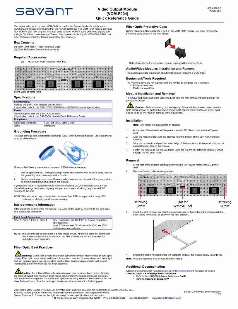
Front View of VOM-F004
Specifications Environmental Refer to the SSP-XXXX chassis specifications. If applicable, refer to the SSP-1200E, SSP-2400 or SSP-3600 chassis specification Power Power supplied from the SSP-XXXX chassis. If applicable, refer to the SSP-XXXX chassis Quick Reference Guide Compliance Safety and Emissions FCC Part 15/CE Mark/C-Tick RoHS Compliant
Grounding Procedure To avoid damage from electrostatic discharge (ESD) when handling modules, use a grounding strap as shown below:
Observe the following precautions to prevent ESD discharge damage: 1. Use an approved ESD wrist grounding strap or an approved wrist or ankle strap. Ensure
the grounding strap makes good skin contact. 2. Before installing or removing a Savant module, connect the clip end of the ground strap
to the threaded grounding stud on the chassis. If you plan to return a replaced module to Savant Systems LLC, immediately place it in the clamshell package that it was originally shipped in or a static shielding bag to avoid ESD damage to the card. NOTE: The wrist strap only protects the component from ESD voltages on the body; ESD
voltages on clothing can still cause damage.
Interconnecting Information After unpacking and inserting the module, interconnect the units by referring to the next table and procedures that follow. Front Panel Connectors Fiber 1, Fiber 2, Fiber 3, Fiber 4 Fiber connection to HRX-F001 or Savant proprietary
fiber receivers. Uses SC-terminated OM3 fiber cable 1000 feet (300 meter) maximum distance.
NOTE: The Savant fiber solutions use a single strand of OM3 fiber optic cable per connection.
Savant recommends that at minimum two fiber strands are run and available for redundancy and expansion.
Fiber Optic Best Practices
Warning: Do not look directly into a fiber optic transceiver or into the ends of fiber optic cables. Fiber optic transceivers and fiber optic cables connected to transceivers emit laser light that can damage your eyes. Do not stare into the laser beam or view it directly with optical instruments even if the interface has been disabled.
Caution: Do not bend fiber optic cables beyond their minimum bend radius. Bending the cables beyond their minimum bend radius can damage the cables and cause problems that are difficult to diagnose. Do not let fiber optic cables hang free from the connector. Do not allow fastened loops of cables to dangle, which stress the cables at the fastening point.
Fiber Optic Protective Caps Before plugging a fiber cable into a port on the VOM-F004 module, you must remove the protective caps, shown in the next image.
Note: Always keep the protective caps on unplugged fiber connections.
Audio/Video Modules Installation and Removal This section provides information about installing and removing a VOM-F004.
Equipment/Tools Required The following items are not supplied and are needed to complete the installation:
• Phillips screwdriver • Module removal tool
Module Installation and Removal To remove and install audio and video modules from the rear of the controller, perform the procedures below.
Caution: Before removing or installing any of the modules, remove power from the SSP-XXXX chassis by setting the power switch to Off (0) and removing the AC power cord. Failure to do so will result in damage to the equipment.
Installation Note: Only install into output slots on chassis.
1. At the rear of the chassis set the power switch to Off (0) and remove the AC power
cord. 2. Align the module edges with the grooves near the bottom of the SSP-XXXX chassis
opening. 3. Slide the module in and push the lower edge of the faceplate until the panel bottoms out
against the rear face of the chassis. 4. Fasten the module to the chassis frame using the two Phillips retaining screws inserted
through the two outer holes
Removal 1. At the rear of the chassis set the power switch to Off (0) and remove the AC power
cord. 2. Remove the two outer retaining screws.
3. Insert the card removal tool into the rectangular slot in the center of the module with the hook facing to the side, as shown in the next diagram.
4. Ensure the tool is hooked behind the faceplate and pull the module gently towards you. Note: The Card Removal Tool comes with the chassis.
Additional Documentation Additional documentation is available at: SavantSystems.com and navigate as follows: > Dealer Login > Knowledge Base > Products.
• Refer to the HRX-F001 Quick Reference Guide • Refer to RacePoint Blueprint™