00704729-its1000m (mini-shelter) quick installation guide(v100r002c02_01) huawei
TRANSCRIPT

8/9/2019 00704729-ITS1000M (Mini-shelter) Quick Installation Guide(V100R002C02_01) HUAWEI
http://slidepdf.com/reader/full/00704729-its1000m-mini-shelter-quick-installation-guidev100r002c0201-huawei 1/50
HUAWEI TECHNOLOGIES CO., LTD.
ITS1000M (Mini-shelter) V100R002C02Quick Installation Guide
Issue: 01
Date: 2011-05-10
8/9/2019 00704729-ITS1000M (Mini-shelter) Quick Installation Guide(V100R002C02_01) HUAWEI
http://slidepdf.com/reader/full/00704729-its1000m-mini-shelter-quick-installation-guidev100r002c0201-huawei 2/501
Contents
Precautions 2
Installation Tools 3
1 Installing Compartments 4
Scenario 1: Overall Installation 4
Scenario 2: Separate Installation 5
2 Installing Racks 11
Installing a 19-inch Rack 11
Installing a Combination Rack 12
Installing a Battery Rack 15
Installing a BTS3900 Rack 17
3 Installing Devices 19Installing Devices into the 19-Inch Rack 19
Installing Storage Batteries 19
Installing the BTS3900 20
Installing the Lamp 20
Installing the RRU 21
4 Installing Cables 21
Cable Routing Specifications 26Connecting Sensors 29
Connecting Ground Cables 30
Connecting Storage Batteries 31
Connecting the Power System 32
Connecting the ACDB 35
Connecting the DCDU 35
Connecting the Monitoring Equipment 36Connecting Temperature Control Equipment 38
Connecting the Communications Cable Between Monitoring Equipment and Base Stations 40
5 Powering On and Commissioning the Mini-shelter 41
Powering On the Mini-shelter 41
Setting the PMU Parameters of Power System 41
Commissioning Environment Monitoring Equipment 42
After the Commissioning 446 Installing Accessories 45
2011
8/9/2019 00704729-ITS1000M (Mini-shelter) Quick Installation Guide(V100R002C02_01) HUAWEI
http://slidepdf.com/reader/full/00704729-its1000m-mini-shelter-quick-installation-guidev100r002c0201-huawei 3/502
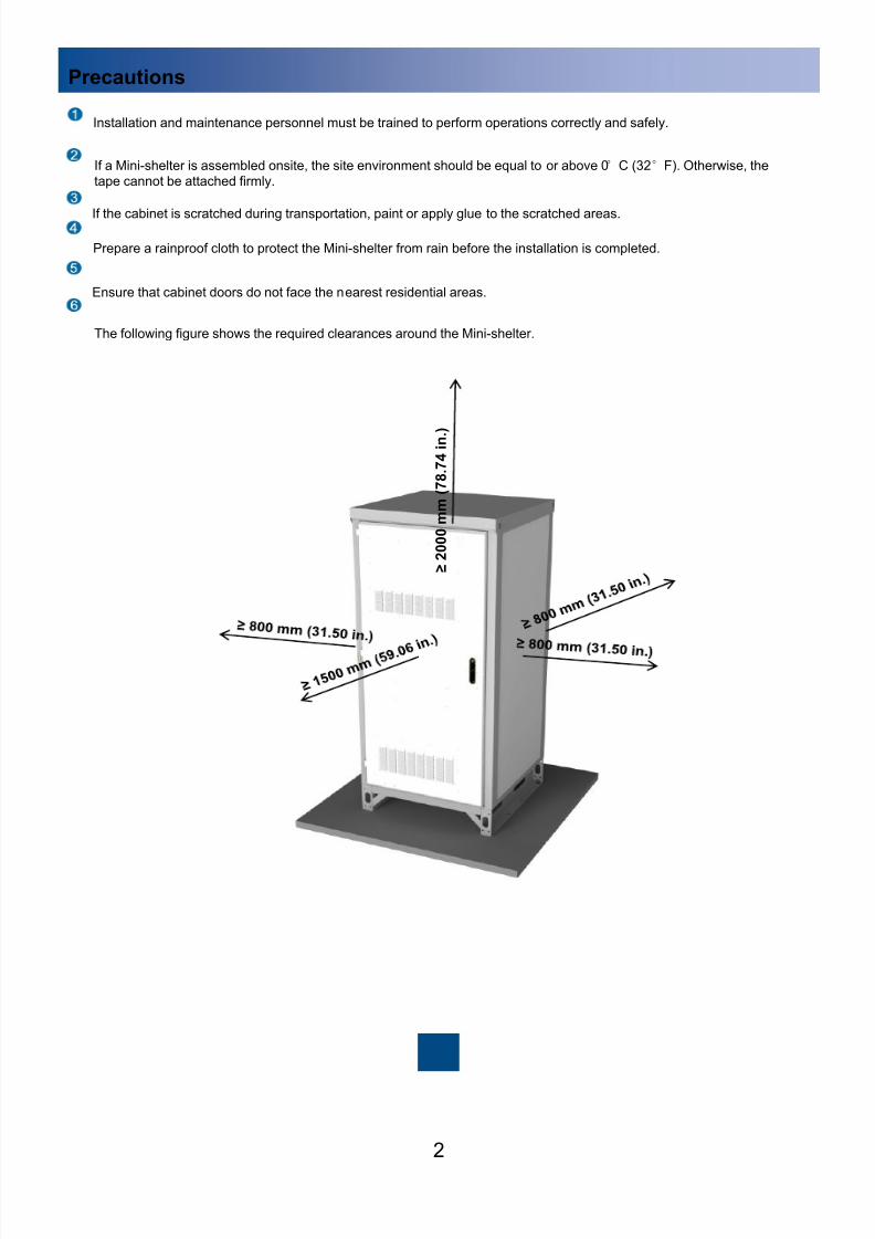
Precautions
Prepare a rainproof cloth to protect the Mini-shelter from rain before the installation is completed.
If the cabinet is scratched during transportation, paint or apply glue to the scratched areas.
If a Mini-shelter is assembled onsite, the site environment should be equal to or above 0°C (32°F). Otherwise, thetape cannot be attached firmly.
The following figure shows the required clearances around the Mini-shelter.
Ensure that cabinet doors do not face the nearest residential areas.
Installation and maintenance personnel must be trained to perform operations correctly and safely.
≥ 2 0 0 0 m m ( 7
8 . 7
4 i n . )

8/9/2019 00704729-ITS1000M (Mini-shelter) Quick Installation Guide(V100R002C02_01) HUAWEI
http://slidepdf.com/reader/full/00704729-its1000m-mini-shelter-quick-installation-guidev100r002c0201-huawei 4/503
Installation Tools
Mandatory Tools
Optional Tools
Flat-head
screwdriver
Phillips
screwdriver
Hammer drill and
Φ16 drill bit
Claw
hammer Multimeter
Adjustable wrench Protective gloves Wire stripper Measuring tape Marker
COAX crimping tool Level
Pallet truck Step ladder M12 lifting eye Rivet gun Φ18 and Φ4.2 drillbits
Segmented
blade utility knife
Crane
A pallet truck is used to transport equipment in the event of overall delivery.
A step ladder is used in scenarios for installing 2.1 m (6.89 ft) high and 2.4 m (7.87 ft) high Mini-shelters and
connecting cables in such Mini-shelters.
An M12 lifting eye is used to hoist an entire Mini-shelter in the event of overall delivery.
A rivet gun is used in scenarios for installing an outdoor ground bar on the rear wall panel of the Mini-shelter.
Φ18 and Φ4.2 drill bits are used in scenarios for installing an outdoor ground bar on a concrete floor or the
rear wall panel of the Mini-shelter.
A crane is used to hoist equipment in the event of overall delivery.
8/9/2019 00704729-ITS1000M (Mini-shelter) Quick Installation Guide(V100R002C02_01) HUAWEI
http://slidepdf.com/reader/full/00704729-its1000m-mini-shelter-quick-installation-guidev100r002c0201-huawei 5/504
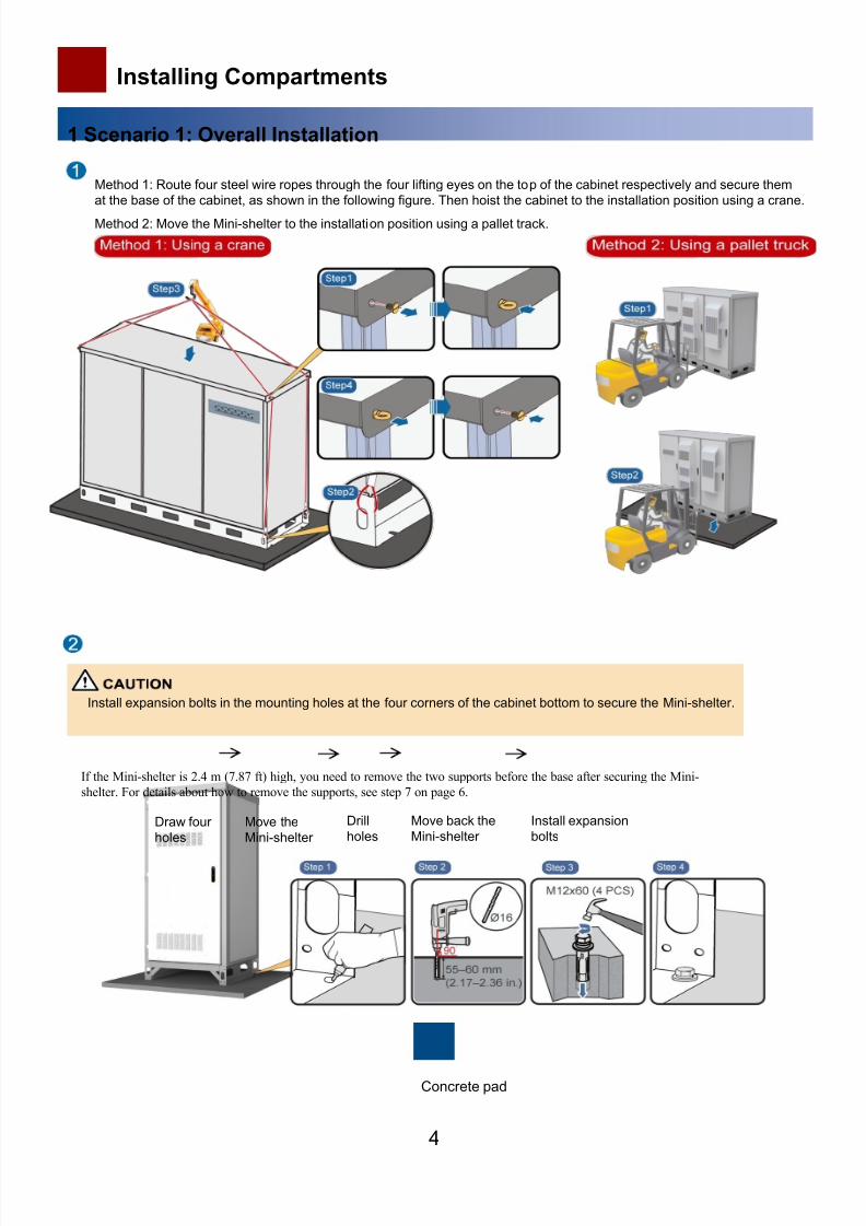
Installing Compartments
1 Scenario 1: Overall Installation
Method 1: Route four steel wire ropes through the four lifting eyes on the top of the cabinet respectively and secure them
at the base of the cabinet, as shown in the following figure. Then hoist the cabinet to the installation position using a crane.
Method 2: Move the Mini-shelter to the installation position using a pallet track.
Install expansion bolts in the mounting holes at the four corners of the cabinet bottom to secure the Mini-shelter.
Concrete pad
Draw four
holes
Move the
Mini-shelter
Drill
holes
Move back the
Mini-shelter
Install expansion
bolts
If the Mini-shelter is 2.4 m (7.87 ft) high, you need to remove the two supports before the base after securing the Mini-
shelter. For details about how to remove the supports, see step 7 on page 6.
8/9/2019 00704729-ITS1000M (Mini-shelter) Quick Installation Guide(V100R002C02_01) HUAWEI
http://slidepdf.com/reader/full/00704729-its1000m-mini-shelter-quick-installation-guidev100r002c0201-huawei 6/50
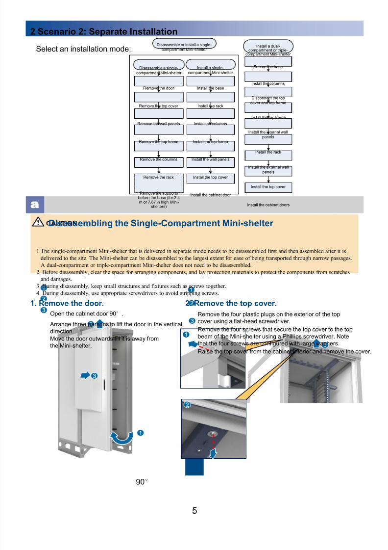
2 Scenario 2: Separate Installation
5
Disassembling the Single-Compartment Mini-shelter
1. Remove the door.
1.The single-compartment Mini-shelter that is delivered in separate mode needs to be disassembled first and then assembled after it is
delivered to the site. The Mini-shelter can be disassembled to the largest extent for ease of being transported through narrow passages.
A dual-compartment or triple-compartment Mini-shelter does not need to be disassembled.
2. Before disassembly, clear the space for arranging components, and lay protection materials to protect the components from scratches
and damages.
3. During disassembly, keep small structures and fixtures such as screws together.4. During disassembly, use appropriate screwdrivers to avoid stripping screws.
Select an installation mode:
90°
Open the cabinet door 90°.
Arrange three persons to lift the door in the vertical
direction.
Move the door outwards till it is away from
the Mini-shelter.
2. Remove the top cover.
Remove the four screws that secure the top cover to the top
beam of the Mini-shelter using a Phillips screwdriver. Note
that the four screws are configured with large washers.
Remove the four plastic plugs on the exterior of the top
cover using a flat-head screwdriver.
Raise the top cover from the cabinet interior and remove the cover.
Remove the rack
Remove the columns
Remove the top frame
Remove the wall panels
Remove the top cover
Secure the base
Install the columnsRemove the door
Install the internal wallpanels
Install the rack
Install the top cover
Install the cabinet doors
Install the top frame
Remove the supportsbefore the base (for 2.4m or 7.87 in high Mini-
shelters)
Install the external wallpanels
Install the base
Install the rack
Install the columns
Install the top frame
Install the wall panels
Install the top cover
Install the cabinet door
Install a dual-compartment or triple-
compartment Mini-shelter
Disassemble a single-
compartment Mini-shelter
Disassemble or install a single-compartment Mini-shelter
Install a single-
compartment Mini-shelter
Disconnect the topcover and top frame

8/9/2019 00704729-ITS1000M (Mini-shelter) Quick Installation Guide(V100R002C02_01) HUAWEI
http://slidepdf.com/reader/full/00704729-its1000m-mini-shelter-quick-installation-guidev100r002c0201-huawei 7/506
3. Remove the wall panels. 4. Remove the top frame.
Remove the eight M5
self-tapping screws
that secure the top
frame to the cabinettop,
Remove the eight M5
screws that secure the
base to the rack, and
then remove the rack.
Remove the two battens beside each wall panel by
pulling them upwards.
Remove the wall panels by pushing them from
the cabinet interior.
5. Remove the columns.
6. Remove the rack.
Remove the four columns by pulling them
upwards from the base.
Remove the eight M5
screws that secure the
base to the rack, and then
remove the rack.
7. Remove the supports for 2.4 m (7.87 in.) high Mini-shelters.
Remove the four M8 screws from the cabinet base using a Phillips
screwdriver, and then remove the two supports.

8/9/2019 00704729-ITS1000M (Mini-shelter) Quick Installation Guide(V100R002C02_01) HUAWEI
http://slidepdf.com/reader/full/00704729-its1000m-mini-shelter-quick-installation-guidev100r002c0201-huawei 8/507
b Installing the Single-Compartment Mini-shelter
1. Secure the base.
1. Determine the door opening direction and then place the base accordingly.
2. Ensure that cabinet doors do not face residential areas.
Draw a line Move the
base
Drill
holes
Move back
the base
Install expansion
bolts
2. Install the rack. 3. Install the columns.
Secure the rack to the
base using eight M5
bolts.
Hole positions at the cabinet bottom
Concrete pad
8/9/2019 00704729-ITS1000M (Mini-shelter) Quick Installation Guide(V100R002C02_01) HUAWEI
http://slidepdf.com/reader/full/00704729-its1000m-mini-shelter-quick-installation-guidev100r002c0201-huawei 9/508
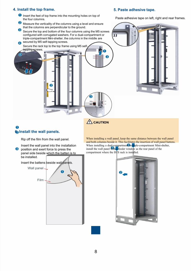
4. Install the top frame.
Paste adhesive tape on left, right and rear frames.
5. Paste adhesive tape.
Insert the feet of top frame into the mounting holes on top of
the four columns.
6. Install the wall panels.
Rip off the film from the wall panel.
Insert the wall panel into the installation
position and exert force to press the
panel side beside which the batten is to
be installed.
Insert the battens beside wall panels.
Measure the verticality of the columns using a level and ensure
that the columns are perpendicular to the ground.
Secure the top and bottom of the four columns using the M5 screwsconfigured with corrugated washers. For a dual-compartment or
triple-compartment Mini-shelter, the columns in the middle are
secured by M5 self-tapping screws.
Secure the rack top to the top frame using M5 self-tapping screws.
When installing a wall panel, keep the same distance between the wall panel
and both columns beside it. This facilitates the insertion of wall panel battens.When installing a dual-compartment or triple-compartment Mini-shelter,
install the wall panel with a feeder window as the rear panel of the
compartment where the BTS rack is installed.

8/9/2019 00704729-ITS1000M (Mini-shelter) Quick Installation Guide(V100R002C02_01) HUAWEI
http://slidepdf.com/reader/full/00704729-its1000m-mini-shelter-quick-installation-guidev100r002c0201-huawei 10/509
7. Install the top cover. 8. Install the compartment door.
Place the top cover onto the top frame.
Install four M5 self-tapping screws and large washers.
Install four plastic plugs.
1. When inserting the top cover, observe the insertion direction
(indicated by the label) to ensure that the top cover points tothe correct direction.
2. After the top cover is installed, push the top cover towards the
direction of the door forcibly to minimize the gap between the
top cover and the rear wall panel.
Raise the compartment door and connect the hinge.
Install the compartment door.
Close the compartment door.
1. The figures are for reference only. For details about howto install a cabinet door, see the related drawings.
2. After installing the Mini-shelter, apply paint or neutral
silicon sealant to scratched areas if necessary.
c Installing the Triple-Compartment Mini-shelter
1. Secure the base.
For details, see step 1 "Secure the base." on page 7.
2. Install the columns.
8/9/2019 00704729-ITS1000M (Mini-shelter) Quick Installation Guide(V100R002C02_01) HUAWEI
http://slidepdf.com/reader/full/00704729-its1000m-mini-shelter-quick-installation-guidev100r002c0201-huawei 11/5010
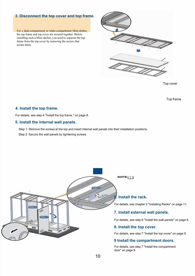
For a dual-compartment or triple-compartment Mini-shelter,
the top frame and top cover are secured together. Before
installing such a Mini-shelter, you need to separate the top
frame from the top cover by removing the screws that
secure them.
Top cover
Top frame
3. Disconnect the top cover and top frame.
For details, see step 4 "Install the top frame." on page 8.
5. Install the internal wall panels.
Step 1: Remove the screws at the top and insert internal wall panels into their installation positions.
Step 2: Secure the wall panels by tightening screws.
6. Install the rack.
8. Install the top cover.
9 Install the compartment doors.
For details, see chapter 2 "Installing Racks" on page 11.
For details, see step 7 "Install the top cover" on page 9.
For details, see step 7 "Install the compartment
door" on page 9.
7. Install external wall panels.
For details, see step 6 "Install the wall panels" on page 8.
4. Install the top frame.
8/9/2019 00704729-ITS1000M (Mini-shelter) Quick Installation Guide(V100R002C02_01) HUAWEI
http://slidepdf.com/reader/full/00704729-its1000m-mini-shelter-quick-installation-guidev100r002c0201-huawei 12/50
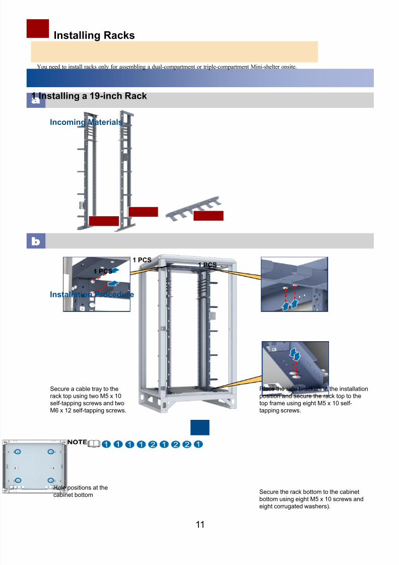
Installing Racks
1 Installing a 19-inch Rack
11
Incoming Materials
b
Installation Procedure
You need to install racks only for assembling a dual-compartment or triple-compartment Mini-shelter onsite.
1 PCS
1 PCS1 PCS
Place the side brackets in the installation
position and secure the rack top to thetop frame using eight M5 x 10 self-
tapping screws.
Secure the rack bottom to the cabinetbottom using eight M5 x 10 screws and
eight corrugated washers).
Secure a cable tray to the
rack top using two M5 x 10self-tapping screws and two
M6 x 12 self-tapping screws.
Hole positions at the
cabinet bottom

8/9/2019 00704729-ITS1000M (Mini-shelter) Quick Installation Guide(V100R002C02_01) HUAWEI
http://slidepdf.com/reader/full/00704729-its1000m-mini-shelter-quick-installation-guidev100r002c0201-huawei 13/50
2 Installing a Combination Rack
12
Incoming Materials
1 PCS
1 PCS
2 PCS
1 PCS
1 PCS
2 PCS
1 PCS 1 PCS
1 PCS
1 PCS
8/9/2019 00704729-ITS1000M (Mini-shelter) Quick Installation Guide(V100R002C02_01) HUAWEI
http://slidepdf.com/reader/full/00704729-its1000m-mini-shelter-quick-installation-guidev100r002c0201-huawei 14/5013
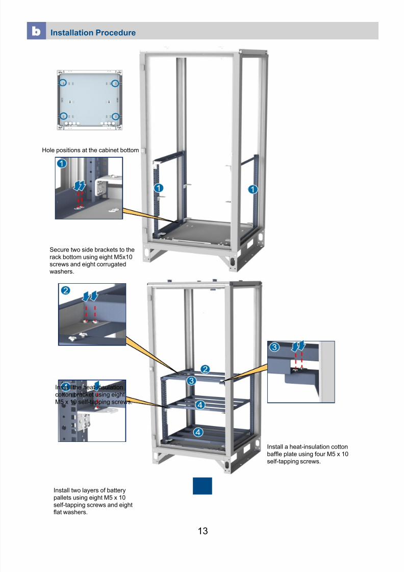
b
Installation Procedure
Hole positions at the cabinet bottom
Secure two side brackets to the
rack bottom using eight M5x10screws and eight corrugated
washers.
Install the heat-insulation
cotton bracket using eight
M5 x 10 self-tapping screws.
Install two layers of battery
pallets using eight M5 x 10
self-tapping screws and eightflat washers.
Install a heat-insulation cotton
baffle plate using four M5 x 10
self-tapping screws.

8/9/2019 00704729-ITS1000M (Mini-shelter) Quick Installation Guide(V100R002C02_01) HUAWEI
http://slidepdf.com/reader/full/00704729-its1000m-mini-shelter-quick-installation-guidev100r002c0201-huawei 15/5014
Install a heat-insulation cotton
on the heat-insulation cotton
bracket according to thearrow direction.
Insert the feet of the 19-inch
rack into the mounting holes in
the heat-insulation cotton and
secure the feet to the heat-
insulation cotton bracket usingeight M5 x 10 self-tapping
screws.
Secure the top of the 19-inch rack to the top frame
using eight M5 x 10 self-
tapping screws.
Secure two connection boxes
to both side brackets
respectively using four M5 x
10 self-tapping screws.
Secure a cable tray to the top of
the 19-inch rack using two M5 x
10 self-tapping screws and two
M6 x 12 self-tapping screws.
8/9/2019 00704729-ITS1000M (Mini-shelter) Quick Installation Guide(V100R002C02_01) HUAWEI
http://slidepdf.com/reader/full/00704729-its1000m-mini-shelter-quick-installation-guidev100r002c0201-huawei 16/50
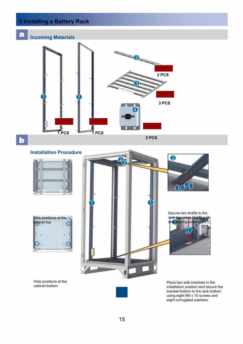
3 Installing a Battery Rack
15
Incoming Materials
b
Installation Procedure
2 PCS
3 PCS
1 PCS1 PCS
2 PCS
Hole positions at the
cabinet bottom
Hole positions at the
cabinet top
Secure two shafts to the
rack top using 16 M5 x 10
self-tapping screws.
Place two side brackets in the
installation position and secure the
bracket bottom to the rack bottomusing eight M5 x 10 screws and
eight corrugated washers.

8/9/2019 00704729-ITS1000M (Mini-shelter) Quick Installation Guide(V100R002C02_01) HUAWEI
http://slidepdf.com/reader/full/00704729-its1000m-mini-shelter-quick-installation-guidev100r002c0201-huawei 17/5016
Install three layers of
battery pallets using 12
M5 x 10 self-tapping
screws and 12 flatwashers.
Secure two connection
boxes to the side brackets
using four M5 x 10 self-
tapping screws.

8/9/2019 00704729-ITS1000M (Mini-shelter) Quick Installation Guide(V100R002C02_01) HUAWEI
http://slidepdf.com/reader/full/00704729-its1000m-mini-shelter-quick-installation-guidev100r002c0201-huawei 18/50
4 Installing a BTS3900 Rack
17
Incoming Materials
b
Installation Procedure
2 PCS
1 PCS
1 PCS1 PCS1 PCS
1 PCS
1 PCS
Hole positions at the
cabinet bottom
Hole positions at thecabinet top
Place two side brackets in theirinstallation positions and secure
two shafts to the rack top using
16 M5 x 10 self-tapping screws.
Secure the bottom of sidebrackets to the rack bottom
using eight M5 x 10 self-
tapping screws and eight flatwashers.
8/9/2019 00704729-ITS1000M (Mini-shelter) Quick Installation Guide(V100R002C02_01) HUAWEI
http://slidepdf.com/reader/full/00704729-its1000m-mini-shelter-quick-installation-guidev100r002c0201-huawei 19/5018
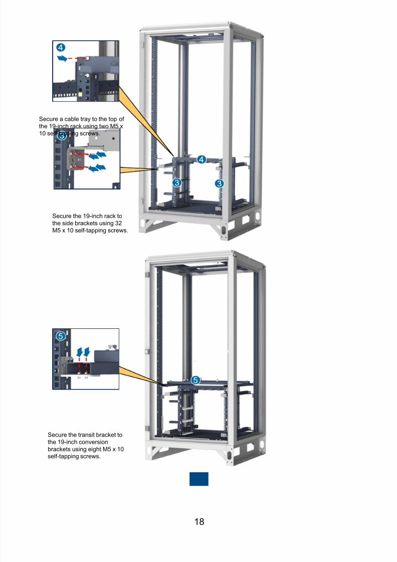
Secure the 19-inch rack to
the side brackets using 32
M5 x 10 self-tapping screws.
Secure a cable tray to the top of
the 19-inch rack using two M5 x
10 self-tapping screws.
Secure the transit bracket to
the 19-inch conversion
brackets using eight M5 x 10self-tapping screws.
8/9/2019 00704729-ITS1000M (Mini-shelter) Quick Installation Guide(V100R002C02_01) HUAWEI
http://slidepdf.com/reader/full/00704729-its1000m-mini-shelter-quick-installation-guidev100r002c0201-huawei 20/50
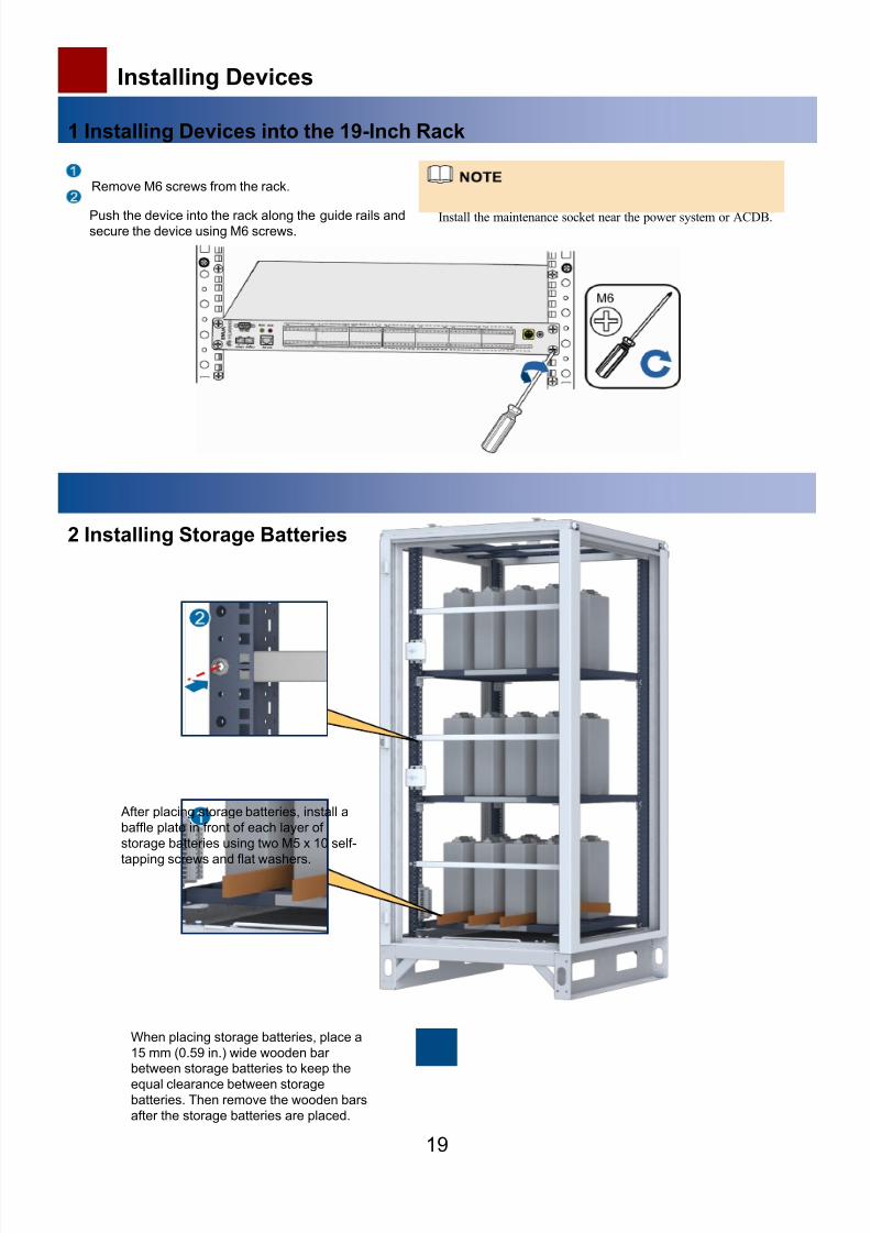
Installing Devices
1 Installing Devices into the 19-Inch Rack
19
2 Installing Storage Batteries
When placing storage batteries, place a
15 mm (0.59 in.) wide wooden barbetween storage batteries to keep the
equal clearance between storagebatteries. Then remove the wooden bars
after the storage batteries are placed.
Remove M6 screws from the rack.
Push the device into the rack along the guide rails andsecure the device using M6 screws.
After placing storage batteries, install a
baffle plate in front of each layer of
storage batteries using two M5 x 10 self-
tapping screws and flat washers.
Install the maintenance socket near the power system or ACDB.

8/9/2019 00704729-ITS1000M (Mini-shelter) Quick Installation Guide(V100R002C02_01) HUAWEI
http://slidepdf.com/reader/full/00704729-its1000m-mini-shelter-quick-installation-guidev100r002c0201-huawei 21/50
3 Installing the BTS3900
20
Adjust the eight square nuts on the transit bracket based
on the four mounting holes in the base.
Install the base.
Place the base onto the transit bracket and align themounting holes in the base with the expansion bolt holes in
the transit bracket. Then secure the base using the four M10x 50 bolts on the transit bracket.
Place the BTS3900 cabinet onto the base.
Push the cabinet along the base till the cabinet rear is
level with the base rear. Then fasten the two M12 x 50
bolts in front of the cabinet using a torque wrench.
4 Installing the Lamp
Install the lamp in the power compartment of the Mini-shelter and enable the power system to supply 48 V direct current
(DC) power to the lamp.
Connect a power cable to the lamp, and mount the lamp on the cable pass ring in the upper part of the 19-inch rack.
Switch on the lamp.
The lamp can be moved to other compartments of the Mini-shelter for equipment maintenance illumination.
48 V DC
8/9/2019 00704729-ITS1000M (Mini-shelter) Quick Installation Guide(V100R002C02_01) HUAWEI
http://slidepdf.com/reader/full/00704729-its1000m-mini-shelter-quick-installation-guidev100r002c0201-huawei 22/50
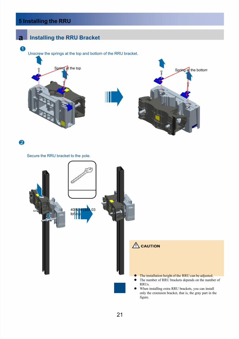
5 Installing the RRU
21
Unscrew the springs at the top and bottom of the RRU bracket.
Spring at the topSpring at the bottom
a Installing the RRU Bracket
Secure the RRU bracket to the pole.
The installation height of the RRU can be adjusted.
The number of RRU brackets depends on the number of
RRUs.
When installing extra RRU brackets, you can install
only the extension bracket, that is, the gray part in the
figure.
40 N.m (354.03lbf.in.)

8/9/2019 00704729-ITS1000M (Mini-shelter) Quick Installation Guide(V100R002C02_01) HUAWEI
http://slidepdf.com/reader/full/00704729-its1000m-mini-shelter-quick-installation-guidev100r002c0201-huawei 23/5022
Secure other RRU brackets to the pole.
Three RRU brackets in the upper layer Two RRU brackets in the lower layer
200 mm
(7.87 in.)235 mm
(9.25 in.)
b Installing the Pole
Mounting ears in the same line should be of the same height. The distance between two adjacent lines
of mounting ears should be 14.5 U (644.525 mm or 25.37 in.).
M6x20 screw
Secure a mounting ear to the rack.
8/9/2019 00704729-ITS1000M (Mini-shelter) Quick Installation Guide(V100R002C02_01) HUAWEI
http://slidepdf.com/reader/full/00704729-its1000m-mini-shelter-quick-installation-guidev100r002c0201-huawei 24/5023
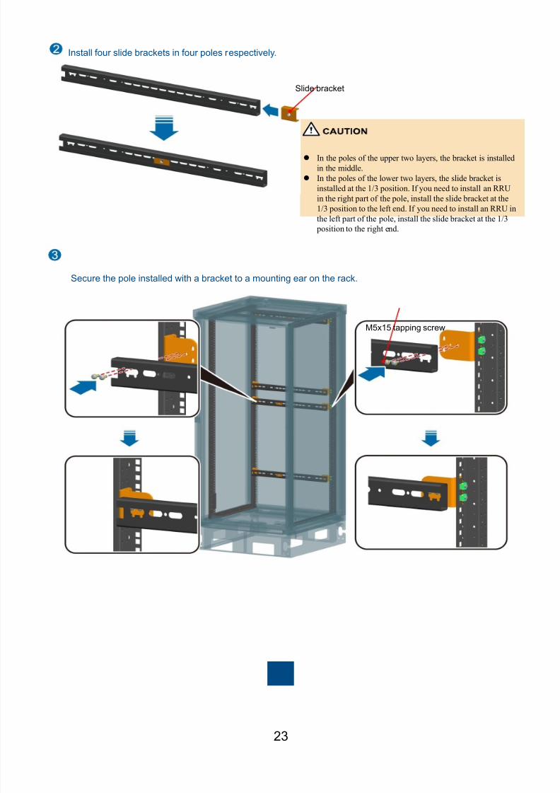
Install four slide brackets in four poles respectively.
In the poles of the upper two layers, the bracket is installed
in the middle.
In the poles of the lower two layers, the slide bracket is
installed at the 1/3 position. If you need to install an RRU
in the right part of the pole, install the slide bracket at the
1/3 position to the left end. If you need to install an RRU in
the left part of the pole, install the slide bracket at the 1/3
position to the right end.
Slide bracket
Secure the pole installed with a bracket to a mounting ear on the rack.
M5x15 tapping screw

8/9/2019 00704729-ITS1000M (Mini-shelter) Quick Installation Guide(V100R002C02_01) HUAWEI
http://slidepdf.com/reader/full/00704729-its1000m-mini-shelter-quick-installation-guidev100r002c0201-huawei 25/5024
Secure both ends of the vertical pole to the bracket in the horizontal pole.
M10x45 bolt
Large washer
Spring washer
c Installing the RRU
Installing the first RRU Installing the second RRU Installing the third RRU
Install RRUs onto the brackets one by one.

8/9/2019 00704729-ITS1000M (Mini-shelter) Quick Installation Guide(V100R002C02_01) HUAWEI
http://slidepdf.com/reader/full/00704729-its1000m-mini-shelter-quick-installation-guidev100r002c0201-huawei 26/5025
The following figure shows the installation rendering of five RRUs.
RRU3201
RRU3201
RRU3201
RRU3232
RRU3232

8/9/2019 00704729-ITS1000M (Mini-shelter) Quick Installation Guide(V100R002C02_01) HUAWEI
http://slidepdf.com/reader/full/00704729-its1000m-mini-shelter-quick-installation-guidev100r002c0201-huawei 27/50
Installing Cables
1 Cable Routing Specifications
26
Single-Compartment Mini-shelter (Functioning as a Distributed Site Cabinet)
Single-Compartment Mini-shelter (Functioning as a Power Cabinet)
Cable Routing Specifications for Typical Configurations
DC power cable
AC power cable
Signal cable
ACDB Power systemMains
EMUA
Heat exchanger
Smokesensor
Temperatureand humidity
sensor
Door statussensor
Watersensor
HUAWEI
base stations
DC power cable
AC power cable
Signal cable
Power systemMains
EMUA
Heat exchanger
BBU
TEC
Smoke
sensor Door status
sensor Watersensor
Temperature andhumidity sensor
Battery string
8/9/2019 00704729-ITS1000M (Mini-shelter) Quick Installation Guide(V100R002C02_01) HUAWEI
http://slidepdf.com/reader/full/00704729-its1000m-mini-shelter-quick-installation-guidev100r002c0201-huawei 28/5027
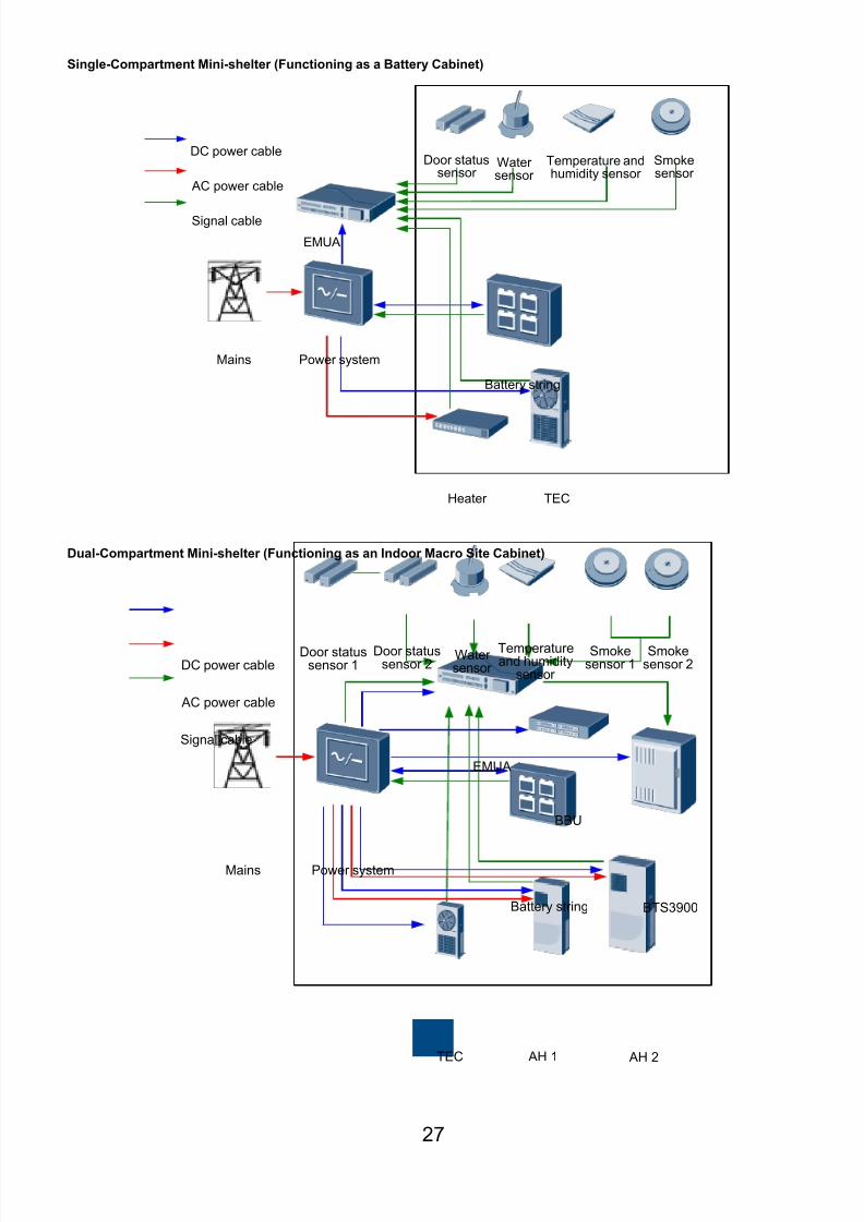
Single-Compartment Mini-shelter (Functioning as a Battery Cabinet)
Dual-Compartment Mini-shelter (Functioning as an Indoor Macro Site Cabinet)
DC power cable
AC power cable
Signal cable
Power systemMains
EMUA
TECHeater
Battery string
Smokesensor
Temperature andhumidity sensor
Watersensor
Door statussensor
DC power cable
AC power cable
Signal cable
Power systemMains
EMUA
TEC
BBU
AH 1 AH 2
BTS3900Battery string
Door statussensor 1
Door statussensor 2
Watersensor
Temperatureand humidity
sensor
Smokesensor 1
Smokesensor 2

8/9/2019 00704729-ITS1000M (Mini-shelter) Quick Installation Guide(V100R002C02_01) HUAWEI
http://slidepdf.com/reader/full/00704729-its1000m-mini-shelter-quick-installation-guidev100r002c0201-huawei 29/5028
Triple-Compartment Mini-shelter (Functioning as an Indoor Macro Site Cabinet)
1. Remove the seal cover from the bottom.
2. Cut a hole in the seal cover along the lines using a
knife or a pair of scissors based on the cross-
sectional area of the cable.
3. Plug the cable hole using the processed seal cover.
The cable can be routed through the hole in the sealcover.
b
Principles for Laying Out Cables
Route cables inside the cabinet.
• Route cables along the cable shelves beside both sides
of the 19-inch rack and the cable try on the rack top.
• Cables in a bundle must be sorted and free from
crosses. Never bind cables at turnings.
• Signal cables and power cables must be bundled
separately, keep them at least 3cm from each other.
Route external cables into the cabinet through the
cable holes at the cabinet bottom.
Cable tray
Cable shelf
DC power cable
AC power cable
Signal cable
Power systemMains
EMUA
ACDB
Heatexchanger 1
Heatexchanger 2
TECHeater
Battery string BTS3900
Door statussensor 1
Door statussensor 2
Door statussensor 3
Watersensor
Temperatureand humidity
sensor
Smokesensor 1
Smokesensor 2
Smokesensor 3
8/9/2019 00704729-ITS1000M (Mini-shelter) Quick Installation Guide(V100R002C02_01) HUAWEI
http://slidepdf.com/reader/full/00704729-its1000m-mini-shelter-quick-installation-guidev100r002c0201-huawei 30/50
8/9/2019 00704729-ITS1000M (Mini-shelter) Quick Installation Guide(V100R002C02_01) HUAWEI
http://slidepdf.com/reader/full/00704729-its1000m-mini-shelter-quick-installation-guidev100r002c0201-huawei 31/50
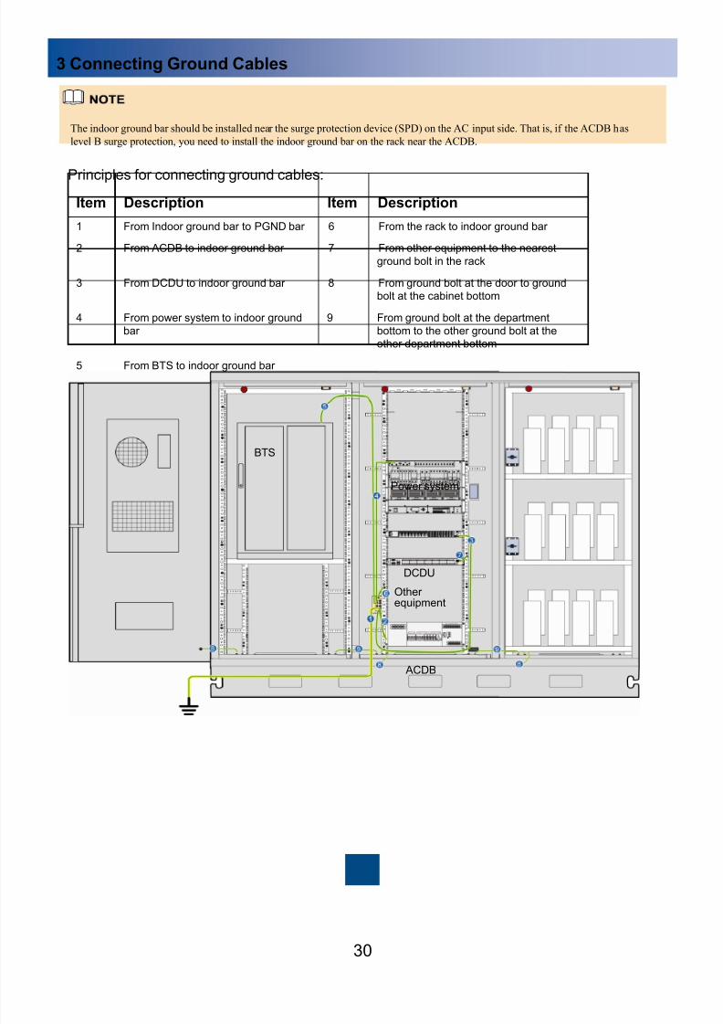
3 Connecting Ground Cables
30
Principles for connecting ground cables:
Item Description Item Description
1 From Indoor ground bar to PGND bar 6 From the rack to indoor ground bar
2 From ACDB to indoor ground bar 7 From other equipment to the nearest
ground bolt in the rack
3 From DCDU to indoor ground bar 8 From ground bolt at the door to groundbolt at the cabinet bottom
4 From power system to indoor ground
bar
9 From ground bolt at the department
bottom to the other ground bolt at theother department bottom
5 From BTS to indoor ground bar
The indoor ground bar should be installed near the surge protection device (SPD) on the AC input side. That is, if the ACDB has
level B surge protection, you need to install the indoor ground bar on the rack near the ACDB.
Power system
DCDU
Otherequipment
ACDB
BTS

8/9/2019 00704729-ITS1000M (Mini-shelter) Quick Installation Guide(V100R002C02_01) HUAWEI
http://slidepdf.com/reader/full/00704729-its1000m-mini-shelter-quick-installation-guidev100r002c0201-huawei 32/50
4 Connecting Storage Batteries
31
Scenario 1: Connecting 2 V Storage Batteries
b Scenario 2: Connecting 12 V Storage Batteries
Four-layer vertical 12 V AGM batteries with one
output
Two groups of 12 V vertical AGM batteries with two
separate outputs
Three-layer vertical 2 V absorbed glass mat (AGM) batteries
Paste the + or – labels on the connection
boxes after connecting storage batteries.
8/9/2019 00704729-ITS1000M (Mini-shelter) Quick Installation Guide(V100R002C02_01) HUAWEI
http://slidepdf.com/reader/full/00704729-its1000m-mini-shelter-quick-installation-guidev100r002c0201-huawei 33/50
5 Connecting the Power System
32
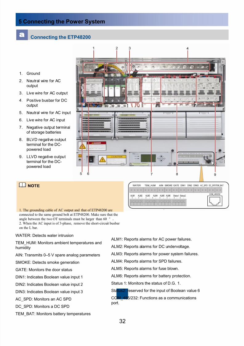
Connecting the ETP48200
WATER: Detects water intrusion
TEM_HUM: Monitors ambient temperatures andhumidity
AIN: Transmits 0 –5 V spare analog parameters
SMOKE: Detects smoke generation
GATE: Monitors the door status
DIN1: Indicates Boolean value input 1
DIN2: Indicates Boolean value input 2
DIN3: Indicates Boolean value input 3
AC_SPD: Monitors an AC SPD
DC_SPD: Monitors a DC SPD
TEM_BAT: Monitors battery temperatures
ALM1: Reports alarms for AC power failures.
ALM2: Reports alarms for DC undervoltage.
ALM3: Reports alarms for power system failures.
ALM4: Reports alarms for SPD failures.
ALM5: Reports alarms for fuse blown.
ALM6: Reports alarms for battery protection.
Status 1: Monitors the status of D.G. 1.
Status2: reserved for the input of Boolean value 6
COM_485/232: Functions as a communications
port.
1. Ground
2. Neutral wire for AC
output
3. Live wire for AC output
4. Positive busbar for DC
output
5. Neutral wire for AC input
6. Live wire for AC input7. Negative output terminal
of storage batteries
8. BLVD negative output
terminal for the DC-
powered load
9. LLVD negative output
terminal for the DC-
powered load
1. The grounding cable of AC output and that of ETP48200 are
connected to the same ground bolt at ETP48200. Make sure that the
angle between the two OT terminals must be larger than 60 °.
2. When the AC input is of 3-phase, remove the short-circuit busbar
on the L bar.

8/9/2019 00704729-ITS1000M (Mini-shelter) Quick Installation Guide(V100R002C02_01) HUAWEI
http://slidepdf.com/reader/full/00704729-its1000m-mini-shelter-quick-installation-guidev100r002c0201-huawei 34/5033
b
Connecting the ETP48150
Connecting the battery temperature sensor
Two white temperature monitoring cables are routed out of the rear of the TETP48150, and white cable terminals are available.
One cable is 3 m (9.84 ft) long and pasted with an Ambient label, and the other cable is 10 m (32.8 ft) long and pasted with aBattery label. The former cable needs to be routed in the equipment compartment, and the latter cable needs to be routed in the
battery compartment. The cables are used to monitor the temperature and are fixed to the rack by using the cable strap. See
the following figure.
Ambient Battery

8/9/2019 00704729-ITS1000M (Mini-shelter) Quick Installation Guide(V100R002C02_01) HUAWEI
http://slidepdf.com/reader/full/00704729-its1000m-mini-shelter-quick-installation-guidev100r002c0201-huawei 35/5034
c
Connecting the TP48300/A
1. Positive busbar for DC output
2. Negative output terminal of
storage batteries3. Negative output terminal for the
DC-powered load
4. AC input
5. Ground
6. Dry contacts for signal cables
The cable to the battery
temperature sensor is
connected to the positive
terminal of storage
batteries.

8/9/2019 00704729-ITS1000M (Mini-shelter) Quick Installation Guide(V100R002C02_01) HUAWEI
http://slidepdf.com/reader/full/00704729-its1000m-mini-shelter-quick-installation-guidev100r002c0201-huawei 36/50
7 Connecting the DCDU
35
6 Connecting the ACDB
Three-phase
Short-circuit busbar
1. AC input
2. Live wire for AC output (LOAD0)
3. Live wire for AC output (LOAD1)
4. Live wire for AC output (LOAD2)
5. Live wire for AC output (LOAD3)
6. Live wire for AC output (LOAD4)
7. Ground
8. Neutral wire for AC output
9. SPD fault alarm
10. Socket
Single-phase
1. Live wire for the AC input
2. Neutral wire for the AC input
3. Live wire for AC output (LOAD0)
4. Live wire for AC output (LOAD1)
5. Live wire for AC output (LOAD2)
6. Live wire for AC output (LOAD3)
7. Live wire for AC output (LOAD4)
8. Ground
9. Neutral wire for AC output
10. SPD fault alarm
11. Socket
8/9/2019 00704729-ITS1000M (Mini-shelter) Quick Installation Guide(V100R002C02_01) HUAWEI
http://slidepdf.com/reader/full/00704729-its1000m-mini-shelter-quick-installation-guidev100r002c0201-huawei 37/50
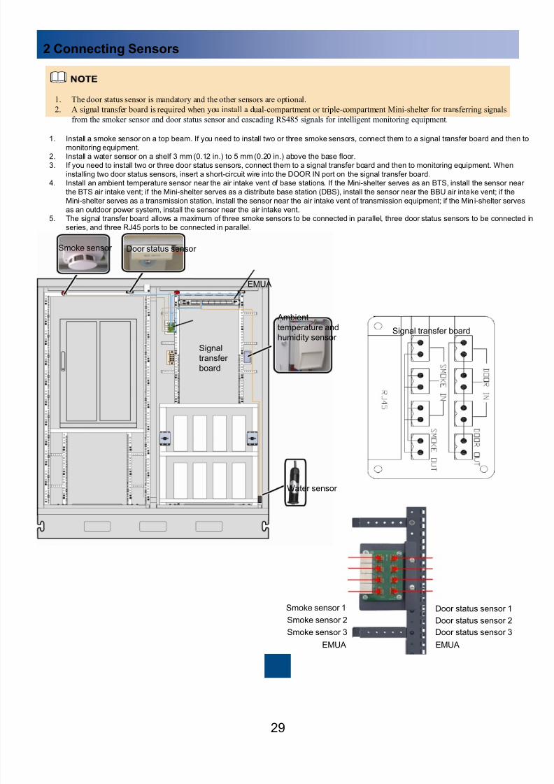
8 Connecting the Monitoring Equipment
36
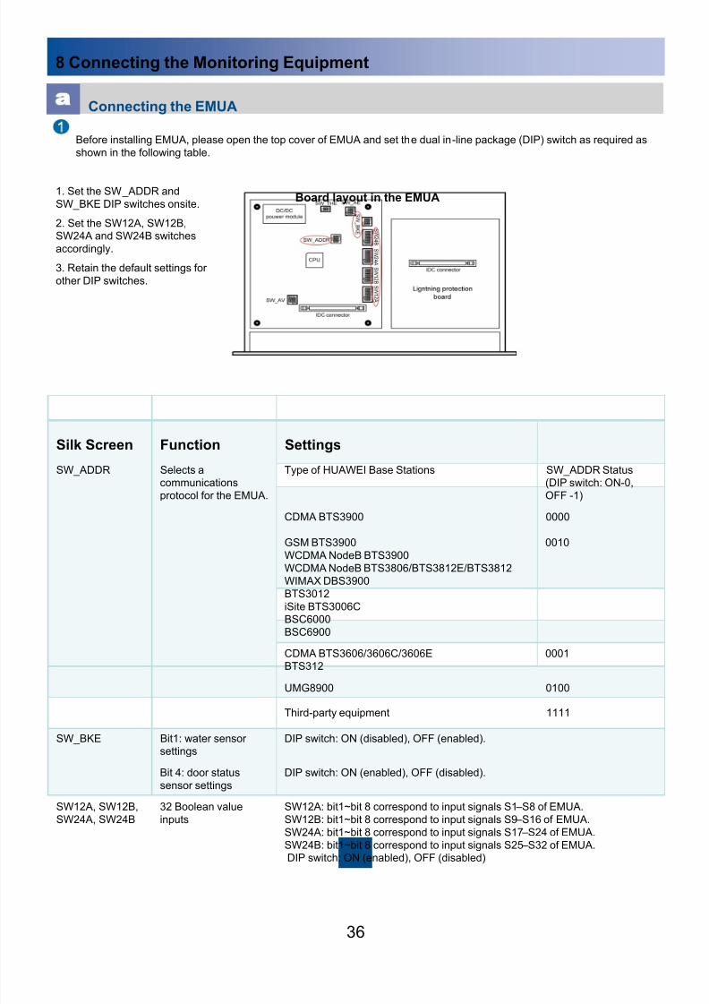
Connecting the EMUA
Before installing EMUA, please open the top cover of EMUA and set the dual in-line package (DIP) switch as required as
shown in the following table.
Silk Screen Function Settings
SW_ADDR Selects acommunications
protocol for the EMUA.
Type of HUAWEI Base Stations SW_ADDR Status(DIP switch: ON-0,
OFF -1)
CDMA BTS3900 0000
GSM BTS3900
WCDMA NodeB BTS3900
WCDMA NodeB BTS3806/BTS3812E/BTS3812
WIMAX DBS3900
BTS3012
iSite BTS3006CBSC6000
BSC6900
0010
CDMA BTS3606/3606C/3606EBTS312
0001
UMG8900 0100
Third-party equipment 1111
SW_BKE Bit1: water sensorsettings
DIP switch: ON (disabled), OFF (enabled).
Bit 4: door status
sensor settings
DIP switch: ON (enabled), OFF (disabled).
SW12A, SW12B,
SW24A, SW24B
32 Boolean value
inputs
SW12A: bit1~bit 8 correspond to input signals S1 –S8 of EMUA.
SW12B: bit1~bit 8 correspond to input signals S9 –S16 of EMUA.
SW24A: bit1~bit 8 correspond to input signals S17 –S24 of EMUA.
SW24B: bit1~bit 8 correspond to input signals S25 –S32 of EMUA.DIP switch: ON (enabled), OFF (disabled)
1. Set the SW_ADDR and
SW_BKE DIP switches onsite.
2. Set the SW12A, SW12B,SW24A and SW24B switches
accordingly.
3. Retain the default settings for
other DIP switches.
Board layout in the EMUA

8/9/2019 00704729-ITS1000M (Mini-shelter) Quick Installation Guide(V100R002C02_01) HUAWEI
http://slidepdf.com/reader/full/00704729-its1000m-mini-shelter-quick-installation-guidev100r002c0201-huawei 38/5037
Connect the EMUA.
8/9/2019 00704729-ITS1000M (Mini-shelter) Quick Installation Guide(V100R002C02_01) HUAWEI
http://slidepdf.com/reader/full/00704729-its1000m-mini-shelter-quick-installation-guidev100r002c0201-huawei 39/50
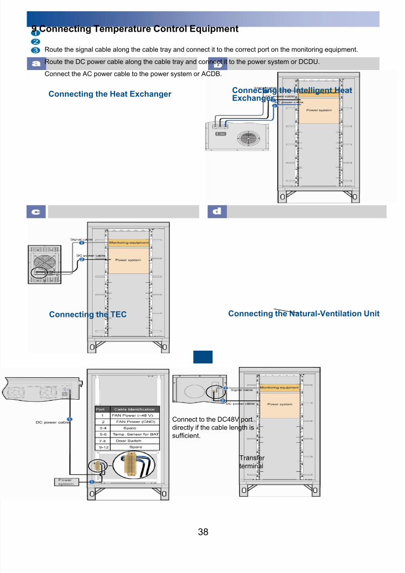
9 Connecting Temperature Control Equipment
38
Connecting the Heat Exchanger
Route the signal cable along the cable tray and connect it to the correct port on the monitoring equipment.
Route the DC power cable along the cable tray and connect it to the power system or DCDU.
Connect the AC power cable to the power system or ACDB.
b
c
Connecting the TECd
Connecting the Intelligent Heat
Exchanger
Connecting the Natural-Ventilation Unit
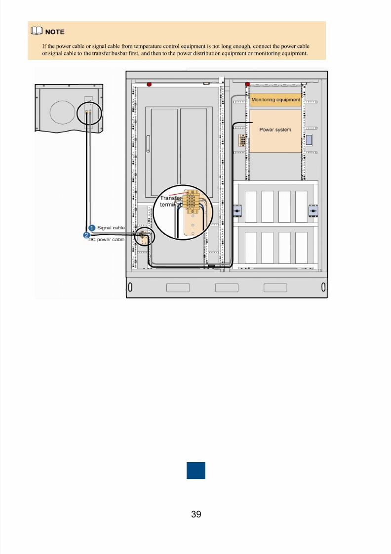
Transfer
terminal
Connect to the DC48V port
directly if the cable length is
sufficient.
8/9/2019 00704729-ITS1000M (Mini-shelter) Quick Installation Guide(V100R002C02_01) HUAWEI
http://slidepdf.com/reader/full/00704729-its1000m-mini-shelter-quick-installation-guidev100r002c0201-huawei 40/5039
If the power cable or signal cable from temperature control equipment is not long enough, connect the power cable
or signal cable to the transfer busbar first, and then to the power distribution equipment or monitoring equipment.

8/9/2019 00704729-ITS1000M (Mini-shelter) Quick Installation Guide(V100R002C02_01) HUAWEI
http://slidepdf.com/reader/full/00704729-its1000m-mini-shelter-quick-installation-guidev100r002c0201-huawei 41/5040
10 Connecting the Communications Cable Between Monitoring Equipment
and Base Stations
Scenario 1: HUAWEI Base Stations
1. The EMUA communicates with HUAWEI base stations over an RS485 port.
2. When the EMUA connects to the base stations, the communications cable on the base stations side needs to be connected to the
MON1 port on the universal power environment interface unit (UPEU) of the BBU.
Connection between the EMUA and the BBU of the BTS3900 GSM, BTS3900 CDMA, BTS3900 UMTS, or DBS3900 WiMAX
Signal cable between the BBU
and the EMUA
b
Scenario 2: Third-Party Equipment
The EMUA communicates with third-party equipment over dry contacts.

8/9/2019 00704729-ITS1000M (Mini-shelter) Quick Installation Guide(V100R002C02_01) HUAWEI
http://slidepdf.com/reader/full/00704729-its1000m-mini-shelter-quick-installation-guidev100r002c0201-huawei 42/50
Powering On and Commissioning the Mini-shelter
1 Powering On the Mini-shelter
41
Check the power distribution cable and the cable label.
Verify that the output voltages of the ACDB, power system, and DCDU meet the following requirements:• AC voltage range: 200 –240 V
• DC voltage range: 38 –58 V
Verify that the DIP switch of the monitoring equipment is set properly.
Power on the Mini-shelter in the sequence as shown in the following figure.
Switch on the mains output circuit breaker
Switch on the ACDB input and load output circuit breakers.
Switch on the AC input circuit breaker on the power system.
Switch on the AC output circuit breakers (located on the power
system) that connect to the DCDU, storage batteries, temperature
control equipment, monitoring equipment, and BBU.
2 Setting the PMU Parameters of Power System
If the battery circuit breakers are switched to the ON position but the LCD on the PMU panel remains blank, flip the battery
switch to the BAT ON position. After 2 minutes, flip the battery switch to the Normal position to avoid battery overdischarge.
If the battery voltage remains low and the PMU is disconnected again after you flip the battery switch to the Normal position,
flip the battery switch to the BAT ON position for 2 minutes after the PMU connects to the mains.
BAT ON
Normal
1
2
Set the number and capacity of battery strings.
Set the date and time.
A customer password is required for accessing the Settings menu,
and a Huawei engineer password is required for accessing the
Eng.Setting menu. The default customer password and Huawei
engineer password are 0# and 11# respectively. Both passwords can
be changed.
8/9/2019 00704729-ITS1000M (Mini-shelter) Quick Installation Guide(V100R002C02_01) HUAWEI
http://slidepdf.com/reader/full/00704729-its1000m-mini-shelter-quick-installation-guidev100r002c0201-huawei 43/5042
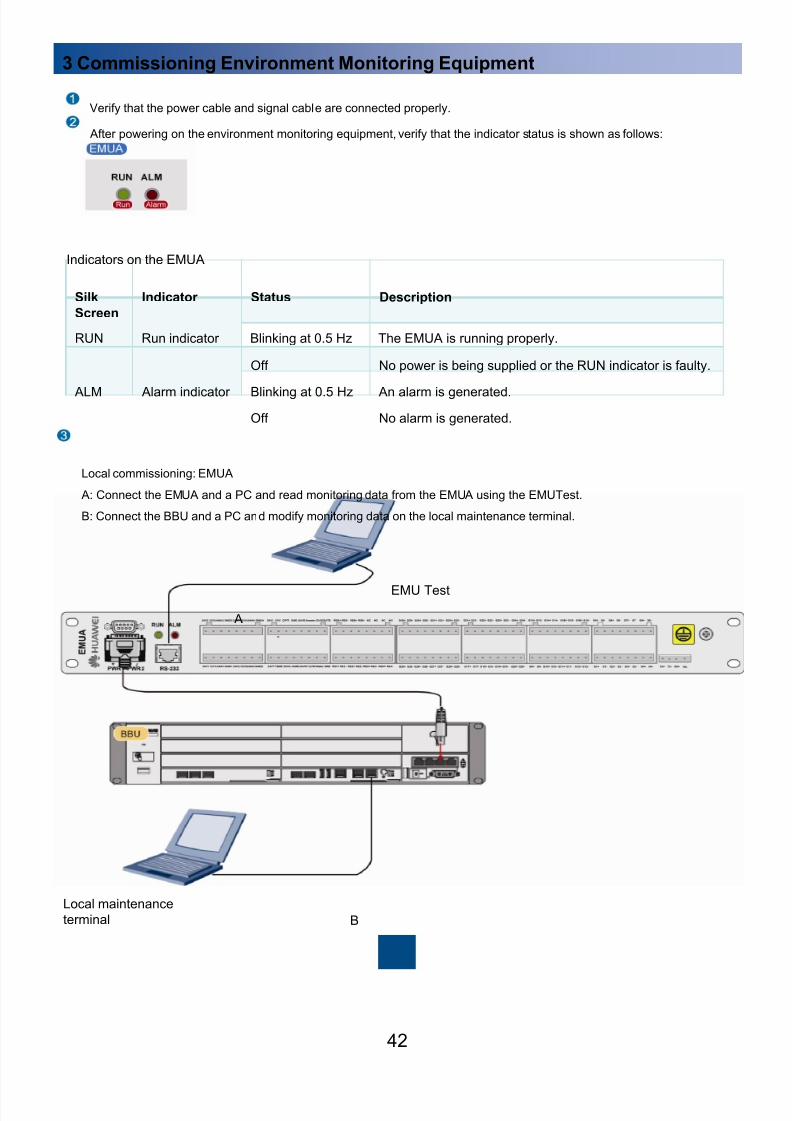
Local commissioning: EMUA
A: Connect the EMUA and a PC and read monitoring data from the EMUA using the EMUTest.
B: Connect the BBU and a PC and modify monitoring data on the local maintenance terminal.
A
B
EMU Test
Local maintenance
terminal
3 Commissioning Environment Monitoring Equipment
Verify that the power cable and signal cable are connected properly.
After powering on the environment monitoring equipment, verify that the indicator status is shown as follows:
Indicators on the EMUA
Silk
Screen
Indicator Status Description
RUN Run indicator Blinking at 0.5 Hz The EMUA is running properly.
Off No power is being supplied or the RUN indicator is faulty.
ALM Alarm indicator Blinking at 0.5 Hz An alarm is generated.
Off No alarm is generated.
8/9/2019 00704729-ITS1000M (Mini-shelter) Quick Installation Guide(V100R002C02_01) HUAWEI
http://slidepdf.com/reader/full/00704729-its1000m-mini-shelter-quick-installation-guidev100r002c0201-huawei 44/5043
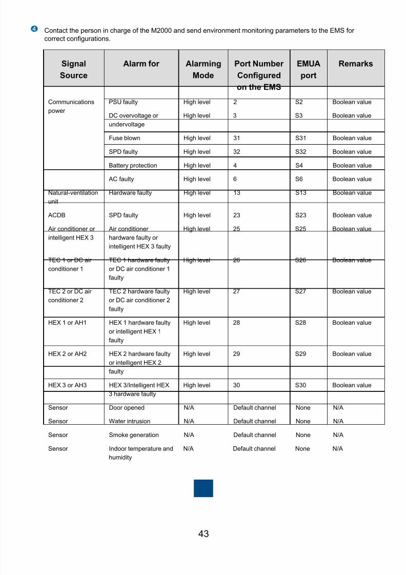
Contact the person in charge of the M2000 and send environment monitoring parameters to the EMS for
correct configurations.
Signal
Source
Alarm for Alarming
Mode
Port Number
Configured
on the EMS
EMUA
port
Remarks
Communications
power
PSU faulty High level 2 S2 Boolean value
DC overvoltage or
undervoltage
High level 3 S3 Boolean value
Fuse blown High level 31 S31 Boolean value
SPD faulty High level 32 S32 Boolean value
Battery protection High level 4 S4 Boolean value
AC faulty High level 6 S6 Boolean value
Natural-ventilation
unit
Hardware faulty High level 13 S13 Boolean value
ACDB SPD faulty High level 23 S23 Boolean value
Air conditioner or
intelligent HEX 3
Air conditioner
hardware faulty or
intelligent HEX 3 faulty
High level 25 S25 Boolean value
TEC 1 or DC air
conditioner 1
TEC 1 hardware faulty
or DC air conditioner 1
faulty
High level 26 S26 Boolean value
TEC 2 or DC air
conditioner 2
TEC 2 hardware faulty
or DC air conditioner 2faulty
High level 27 S27 Boolean value
HEX 1 or AH1 HEX 1 hardware faulty
or intelligent HEX 1
faulty
High level 28 S28 Boolean value
HEX 2 or AH2 HEX 2 hardware faulty
or intelligent HEX 2
faulty
High level 29 S29 Boolean value
HEX 3 or AH3 HEX 3/Intelligent HEX
3 hardware faulty
High level 30 S30 Boolean value
Sensor Door opened N/A Default channel None N/A
Sensor Water intrusion N/A Default channel None N/A
Sensor Smoke generation N/A Default channel None N/A
Sensor Indoor temperature and
humidity
N/A Default channel None N/A
8/9/2019 00704729-ITS1000M (Mini-shelter) Quick Installation Guide(V100R002C02_01) HUAWEI
http://slidepdf.com/reader/full/00704729-its1000m-mini-shelter-quick-installation-guidev100r002c0201-huawei 45/5044
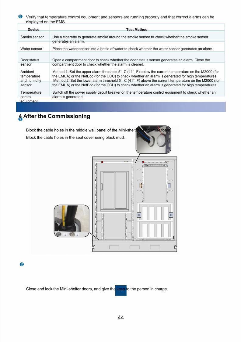
4 After the Commissioning
Block the cable holes in the middle wall panel of the Mini-shelter using white foam.
Block the cable holes in the seal cover using black mud.
Close and lock the Mini-shelter doors, and give the keys to the person in charge.
Verify that temperature control equipment and sensors are running properly and that correct alarms can be
displayed on the EMS.
Device Test Method
Smoke sensor Use a cigarette to generate smoke around the smoke sensor to check whether the smoke sensor
generates an alarm.
Water sensor Place the water sensor into a bottle of water to check whether the water sensor generates an alarm.
Door statussensor
Open a compartment door to check whether the door status sensor generates an alarm. Close thecompartment door to check whether the alarm is cleared.
Ambient
temperature
and humidity
sensor
Method 1: Set the upper alarm threshold 5°C (41°F) below the current temperature on the M2000 (for
the EMUA) or the NetEco (for the CCU) to check whether an alarm is generated for high temperatures.
Method 2: Set the lower alarm threshold 5°C (41°F) above the current temperature on the M2000 (for
the EMUA) or the NetEco (for the CCU) to check whether an alarm is generated for high temperatures.
Temperature
control
equipment
Switch off the power supply circuit breaker on the temperature control equipment to check whether an
alarm is generated.

8/9/2019 00704729-ITS1000M (Mini-shelter) Quick Installation Guide(V100R002C02_01) HUAWEI
http://slidepdf.com/reader/full/00704729-its1000m-mini-shelter-quick-installation-guidev100r002c0201-huawei 46/50
Installing Accessories
1 Installing an Outdoor Ground Bar
45
An outdoor ground bar can be installed in the following three positions:
On the steel base of the Mini-shelter (recommended)
Under the feeder window in the rear wall panel of the Mini-shelter
On the concrete floor around the Mini-shelter

8/9/2019 00704729-ITS1000M (Mini-shelter) Quick Installation Guide(V100R002C02_01) HUAWEI
http://slidepdf.com/reader/full/00704729-its1000m-mini-shelter-quick-installation-guidev100r002c0201-huawei 47/50
2 Combining Single-Compartment Mini-shelters
46
1. Cables from one Mini-shelter are routed into the other Mini-shelter through the cables holes at the cabinet bottom and corrugated
pipes.
2. For ease of turning at the cabinet bottom, use flexible corrugated pipes with the external diameter of 44 mm (1.73 in.) and the
shortest internal diameter of 32 mm (1.26 in.) in the areas with the ambient temperatures above – 10°C (14°F); use stainless
corrugated pipes with the external diameter of 44 mm (1.73 in.) and the shortest internal diameter of 31.8 mm (1.25 in.) in the areaswith the ambient temperatures below – 10°C (14°F).
Place the L-type nut basebeside the base interior and
align the nut holes with the
holes in the base. Then
secure the nut base to an L-
type connection plate using
eight M8 x 25 bolts.
L-type nut
base
L-type
connectionplate
L-type nut base
L-type connection
plateBase
Concrete
pad
M8 bolt
Open the door lock using a key tothe degree as shown in the
following figure.
Unscrew the lock cylinder using a
Phillips screwdriver.Install a new lock cylinder and
secure it using screws.
To replace a lock cylinder of a door lock, perform the following steps:
3 Replacing Lock Cylinders

8/9/2019 00704729-ITS1000M (Mini-shelter) Quick Installation Guide(V100R002C02_01) HUAWEI
http://slidepdf.com/reader/full/00704729-its1000m-mini-shelter-quick-installation-guidev100r002c0201-huawei 48/50
4 Installing Antitheft Fences
47
5 Installing an Awning
Place side fences on the left and
right sides of the Mini-shelter and
secure the fences to the base usingeight M8 x 20 anti-theft screws.
Hang the mounting ears of front and
rear fences onto side fences. A lock
can be installed in the hole under each
mounting ear for security strengthening.
Secure the front and rear
fences to side fences using
eight M8 x 20 anti-theftscrews.
Normally, an awning provides a roof for a Mini-shelter.
An awning can protect maintenance personnel from rain after being pulled out.
8/9/2019 00704729-ITS1000M (Mini-shelter) Quick Installation Guide(V100R002C02_01) HUAWEI
http://slidepdf.com/reader/full/00704729-its1000m-mini-shelter-quick-installation-guidev100r002c0201-huawei 49/5048
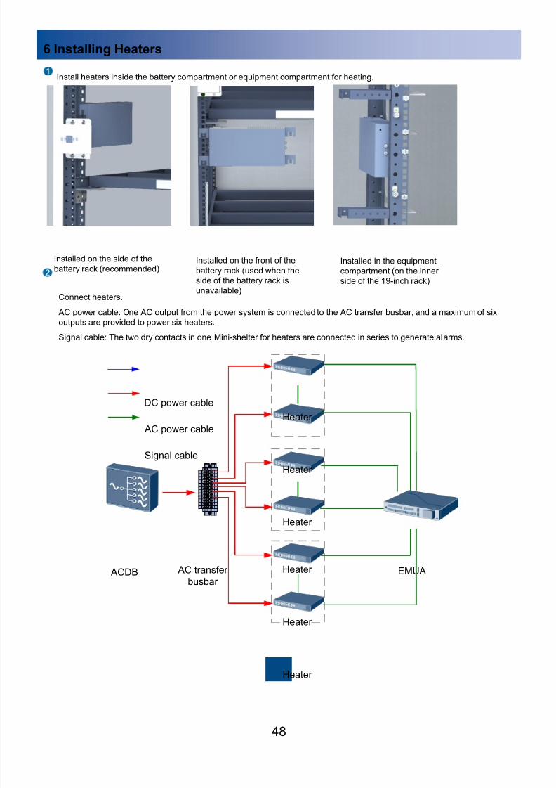
Install heaters inside the battery compartment or equipment compartment for heating.
Installed on the side of thebattery rack (recommended)
Installed on the front of the
battery rack (used when the
side of the battery rack isunavailable)
Installed in the equipmentcompartment (on the inner
side of the 19-inch rack)
6 Installing Heaters
Connect heaters.
AC power cable: One AC output from the power system is connected to the AC transfer busbar, and a maximum of six
outputs are provided to power six heaters.
Signal cable: The two dry contacts in one Mini-shelter for heaters are connected in series to generate alarms.
DC power cable
AC power cable
Signal cable
EMUA ACDB
Heater
AC transfer
busbar
Heater
Heater
Heater
Heater
Heater

8/9/2019 00704729-ITS1000M (Mini-shelter) Quick Installation Guide(V100R002C02_01) HUAWEI
http://slidepdf.com/reader/full/00704729-its1000m-mini-shelter-quick-installation-guidev100r002c0201-huawei 50/50
HUAWEI TECHNOLOGIES CO LTD