001-egx-350 use en r4 - roland care service &...
TRANSCRIPT

USER'S MANUAL
➢ To ensure safe usage and full performance of this product, please be sure to read through thismanual completely.
➢ To ensure immediate access whenever needed, store this manual in a safe location.➢ Unauthorized copying, quotation, or translation of this manual, in whole or in part, without the
written approval of Roland DG Corp., is prohibited.➢ The contents of this document and the specifications of this product are subject to change without
notice.➢ Roland DG Corp. assumes no responsibility for any loss or damage relating to this product, regard-
less of any defect in this product or this manual. Such loss or damage, whether direct or indirect,includes, but is not limited to, that arising from the specifications or performance of this product,that due to failure of the product to perform, and that arising from any article made using thisproduct.
For the USA
FEDERAL COMMUNICATIONS COMMISSIONRADIO FREQUENCY INTERFERENCE
STATEMENT
This equipment has been tested and found to comply with thelimits for a Class A digital device, pursuant to Part 15 of theFCC Rules.These limits are designed to provide reasonable protectionagainst harmful interference when the equipment is operatedin a commercial environment.This equipment generates, uses, and can radiate radiofrequency energy and, if not installed and used in accordancewith the instruction manual, may cause harmful interferenceto radio communications.Operation of this equipment in a residential area is likely tocause harmful interference in which case the user will berequired to correct the interference at his own expense.
Unauthorized changes or modification to this system can voidthe users authority to operate this equipment.
The I/O cables between this equipment and the computingdevice must be shielded.
For Canada
CLASS A NOTICE
This Class A digital apparatus meets all requirements of theCanadian Interference-Causing Equipment Regulations.
CLASSE A AVIS
Cet appareil numérique de la classe A respecte toutes lesexigences du Règlement sur le matériel brouilleur duCanada.
NOTICEGrounding Instructions
Do not modify the plug provided - if it will not fit the outlet, havethe proper outlet installed by a qualified electrician.
Check with qualified electrician or service personnel if thegrounding instructions are not completely understood, or if indoubt as to whether the tool is properly grounded.
Use only 3-wire extension cords that have 3-prong groundingplugs and 3-pole receptacles that accept the tool’s plug.
Repair or replace damaged or worn out cord immediately.
Operating Instructions
KEEP WORK AREA CLEAN. Cluttered areas and benchesinvites accidents.
DON’T USE IN DANGEROUS ENVIRONMENT. Don’t usepower tools in damp or wet locations, or expose them to rain.Keep work area well lighted.
DISCONNECT TOOLS before servicing; when changingaccessories, such as blades, bits, cutters, and like.
REDUCE THE RISK OF UNINTENTIONAL STARTING.Make sure the switch is in off position before plugging in.
USE RECOMMENDED ACCESSORIES. Consult the owner’smanual for recommended accessories. The use of improperaccessories may cause risk of injury to persons.
NEVER LEAVE TOOL RUNNING UNATTENDED. TURNPOWER OFF. Don’t leave tool until it comes to a completestop.
WARNINGThis is a Class A product. In a domestic environment this product may cause radio interference in which case the usermay be required to take adequate measures.
Manufacturer:ROLAND DG CORPORATION1-6-4 Shinmiyakoda, Kita-ku, Hamamatsu-shi, Shizuoka-ken, 431-2103 JAPAN
The authorized representative in the EU:Roland DG Corporation, German Office Halskestr.7 47877 Willich,Germany
For EU Countries
Roland DG Corp. has licensed the MMP technology from the TPL Group.
WARNINGThis product contains chemicals known to cause cancer,birth defects and other reproductive harm, including lead.
For California
For EU Countries

1
Contents
To Ensure Safe Use ....................................................................................................................... 4
Pour utiliser en toute sécurité .................................................................................................. 11
Important Notes on Handling and Use ........................................................................................... 18
About the Documentation for This Machine................................................................................... 19
Chapter 1 Getting Started .............................................................................................................. 21
1-1 Machine Highlights ............................................................................................................................................. 22Features ......................................................................................................................................... 22
1-2 Part Names and Functions ............................................................................................................................... 23Front and Interior ........................................................................................................................... 23Side ............................................................................................................................................... 24
Chapter 2 Installation and Setup .................................................................................................... 25
2-1 Checking the Included Items ........................................................................................................................... 262-2 Installation ............................................................................................................................................................ 27
About Emplacement and Installation ............................................................................................. 27Installation Environment ................................................................................................................ 27Unpacking ..................................................................................................................................... 29
2-3 Cable Connections ............................................................................................................................................. 30Connecting the Handy Panel ......................................................................................................... 30Connecting the Power Cord .......................................................................................................... 31Connecting a Computer Via a Communication Cable ................................................................... 32
2-4 Selecting the Language ...................................................................................................................................... 33Selecting the Language Used for Text on the Display Screen ......................................................... 33
2-5 Before Starting Operations .............................................................................................................................. 35Spindle Run-in (Warm-up) ............................................................................................................. 35
Chapter 3 Basic Operation............................................................................................................... 37
3-1 Types of Emergency Stops to Ensure Safety ................................................................................................. 38How to Perform an Emergency Stop .............................................................................................. 38To Cancel an Emergency Stop ....................................................................................................... 38Emergency Stop Due to Opening or Closing the Front Cover ........................................................ 39
3-2 Starting and Quitting ......................................................................................................................................... 40How to Start the Machine .............................................................................................................. 40Shutdown ...................................................................................................................................... 41
3-3 Using the Handy Panel ...................................................................................................................................... 423-4 Moving the Cutter .............................................................................................................................................. 43
Terms Indicating the Cutter Position .............................................................................................. 43Viewing the Cutter Position ........................................................................................................... 43Manual Movement ........................................................................................................................ 44Moving to a Specific Position Automatically ................................................................................. 45
3-5 Spindle Operation .............................................................................................................................................. 47Starting and Stopping Spindle Rotation ......................................................................................... 47Adjusting the Spindle Speed .......................................................................................................... 48
3-6 Pausing and Stopping Cutting .......................................................................................................................... 49Pausing and Resuming Cutting ...................................................................................................... 49Stopping Cutting ............................................................................................................................ 50
Chapter 4 Engraving.......................................................................................................................... 51
4-1 Flow of Engraving Operations ......................................................................................................................... 524-2 Mounting a Workpiece ...................................................................................................................................... 54

Contents
2
4-3 Selection of the Cutter (Usage Examples) ................................................................................................... 554-4 Cutter Installation Method 1 (With Nose Unit) ........................................................................................ 56
Installing a Character Cutter (With Nose Unit) .............................................................................. 56Important Notes When Using the Nose Unit ................................................................................. 61
4-5 Cutter Installation Method 2 (No Nose Unit) ............................................................................................ 62Installing a Character Cutter (With No Nose Unit) ........................................................................ 62
4-6 Cutter Installation Method 3 (Diamond Scraper) ...................................................................................... 67Installing a Diamond Scraper ........................................................................................................ 67
4-7 Cutter Installation Method 4 (End mill) ........................................................................................................ 71Installing a End Mill ....................................................................................................................... 71
4-8 Setting the XY Origin Point ............................................................................................................................. 75Setting the XY Origin Point (Home Position) ................................................................................. 75
4-9 Performing Engraving ......................................................................................................................................... 76Performing Engraving .................................................................................................................... 76Adjusting the Cutter Feed Rate During Engraving (Override) ......................................................... 77Executing Repeated Cutting ........................................................................................................... 78
Chapter 5 Feature reference ............................................................................................................ 79
5-1 Attaching the Vacuum Adapter for Chip Cleaning ...................................................................................... 80Using the Vacuum Adapter ............................................................................................................ 80
5-2 The Position of the Lock Lever ....................................................................................................................... 825-3 Surface Leveling of the Workpiece Table ...................................................................................................... 835-4 Menu List .............................................................................................................................................................. 84
Main Menu .................................................................................................................................... 84Submenus ...................................................................................................................................... 85Origin-setting Menu ...................................................................................................................... 86Pause Menu ................................................................................................................................... 86Copy Menu.................................................................................................................................... 87
5-5 Description of Menu Items .............................................................................................................................. 88Main Menu .................................................................................................................................... 88I/O Menu (Submenu) ..................................................................................................................... 89Others Menu (Submenu) ............................................................................................................... 90Adjustment Menu (Submenu) ........................................................................................................ 91Origin-setting Menu ...................................................................................................................... 92Pause Menu ................................................................................................................................... 93Copy Menu.................................................................................................................................... 93
Chapter 6 Maintenance .................................................................................................................... 95
6-1 Daily Care ............................................................................................................................................................. 96Cleaning ........................................................................................................................................ 96Cleaning Inside the Front Cover .................................................................................................... 96Cleaning Around the Spindle ........................................................................................................ 97
6-2 Maintenance and Inspection ............................................................................................................................. 98Spindle Maintenance ..................................................................................................................... 98
Chapter 7 Troubleshooting .............................................................................................................. 99
7-1 Troubleshooting (Engraving) ........................................................................................................................... 100The cutting-in depth is not uniform (when using the nose unit). .................................................. 100The cutting-in depth is not uniform (when not using the nose unit). ........................................... 100The cutter leaves tracks at places where cutting-in starts or where lines change direction. ......... 100An engraved bottom surface is rough or burring remains. ........................................................... 100Engraved lines are uneven or wavy. ............................................................................................. 100
7-2 Troubleshooting (Operation) ......................................................................................................................... 101The power does not come on ...................................................................................................... 101Initialization is not performed or initialization fails ..................................................................... 101
Contents
3
Operations are ignored. ............................................................................................................... 101Abnormal cutting is performed .................................................................................................... 101The spindle doesn’t rotate during engraving. ............................................................................... 101Descent doesn’t stop (when automatic Z control is on). .............................................................. 101The USB cable came loose during engraving. ............................................................................. 102
7-3 Responding to a Message ............................................................................................................................... 1037-4 Responding to an Error Message .................................................................................................................. 104
Chapter 8 Appendix ........................................................................................................................ 107
8-1 Examples of Settings for Cutting Parameters ............................................................................................ 108Example Settings ......................................................................................................................... 108Tips for Fine-tuning ..................................................................................................................... 108
8-2 Location of Power Rating and Serial Number Label ................................................................................ 1098-3 Interface Specifications .................................................................................................................................... 110
Serial Connector .......................................................................................................................... 110Expansion Connector .................................................................................................................. 111
8-4 Main Unit Specification .................................................................................................................................... 112Dimensions of Outline ................................................................................................................ 112Work area .................................................................................................................................... 113Workpiece-table Installation-area Dimensional Drawing ............................................................ 114Main Specifications ..................................................................................................................... 115System Requirements for USB Connection .................................................................................. 115
http://www.rolanddg.com/Copyright © 2007-2008 Roland DG Corporation
Company names and product names are trademarks or registered trademarks of their respective holders.

4
To Ensure Safe Use
Improper handling or operation of this machine may result in injury or damage to property. Points whichmust be observed to prevent such injury or damage are described as follows.
About WARNING and CAUTION Notices
Used for instructions intended to alert the user to the risk of death or severeinjury should the unit be used improperly.
Used for instructions intended to alert the user to the risk of injury or materialdamage should the unit be used improperly.
Note: Material damage refers to damage or other adverse effects caused withrespect to the home and all its furnishings, as well to domestic animalsor pets.
WARNING
CAUTION
About the Symbols
The symbol alerts the user to important instructions or warnings. The specific meaning ofthe symbol is determined by the design contained within the triangle. The symbol at left means"danger of electrocution."
The symbol alerts the user to items that must never be carried out (are forbidden). Thespecific thing that must not be done is indicated by the design contained within the circle. Thesymbol at left means the unit must never be disassembled.
The symbol alerts the user to things that must be carried out. The specific thing that must bedone is indicated by the design contained within the circle. The symbol at left means the power-cord plug must be unplugged from the outlet.

To Ensure Safe Use
5
Incorrect operation may cause injury.
WARNING
Be sure to follow the operation proce-dures described in this documentation.Never allow anyone unfamiliar with theusage or handling of the machine to touchit.Incorrect usage or handling may lead to an acci-dent.
Keep children away from the machine.The machine includes areas and componentsthat pose a hazard to children and may result ininjury, blindness, choking, or other serious acci-dent.
Never operate the machine while tired orafter ingesting alcohol or any medication.Operation requires unimpaired judgment. Im-paired judgment may result in an accident.
Conduct operations in a clean, brightly litlocation.Working in a location that is dark or clutteredmay lead to an accident, such as becoming caughtin the machine as the result of an inadvertentstumble.
Never use the machine for any purposefor which it is not intended, or use themachine in an undue manner that exceedsits capacity.Doing so may result in injury or fire.
Never use a cutting tool that has becomedull. Perform frequent maintenance tokeep and use the machine in good work-ing order.Unreasonable usage may result in fire or injury.
For accessories (optional and consumableitems, power cord, and the like), use onlygenuine articles compatible with this ma-chine.Incompatible items may lead to an accident.
Before attempting cleaning, maintenance,or attachment or detachment of optionalitems, disconnect the power cord.Attempting such operations while the machineis connected to a power source may result ininjury or electrical shock.
WARNING
Never attempt to disassemble, repair, ormodify the machine.Doing so may result in fire, electrical shock, orinjury. Entrust repairs to a trained service tech-nician.
CAUTION
Never climb or lean on the machine.The machine is not made to support a person.Climbing or leaning on the machine may dis-lodge components and cause a slip or fall, re-sulting in injury.

To Ensure Safe Use
6
This machine weighs 34 kg (75 lb.)
CAUTION
Unloading and emplacement are opera-tions that must be performed by 2 per-sons or more.Tasks that require undue effort when performedby a small number of persons may result in physi-cal injury. Also, if dropped, such items may causeinjury.
CAUTION
Install in a location that is level and stable.Installation in an unsuitable location may causean accident, including a fall or tipover.
WARNING
Never attempt to cut magnesium or anyother such flammable material.Fire may occur during cutting.
Keep open flame away from the work area.Cutting waste may ignite. Powdered material isextremely flammable, and even metal materialmay catch fire.
When using a vacuum cleaner to take upcutting waste, exercise caution to preventfire or dust explosion.Taking up fine cuttings using an ordinary vacuumcleaner may cause danger of fire or explosion.Check with the manufacturer of the vacuumcleaner. When the safety of use cannot be de-termined, clean using a brush or the like, with-out using the vacuum cleaner.
CAUTION
Wear dust goggles and a mask. Wash awayany cutting waste remaining on the hands.Accidentally swallowing or inhaling cutting wastemay be hazardous to the health.
The cutting waste or workpiece may catch fire or pose a health hazard.
To Ensure Safe Use
7
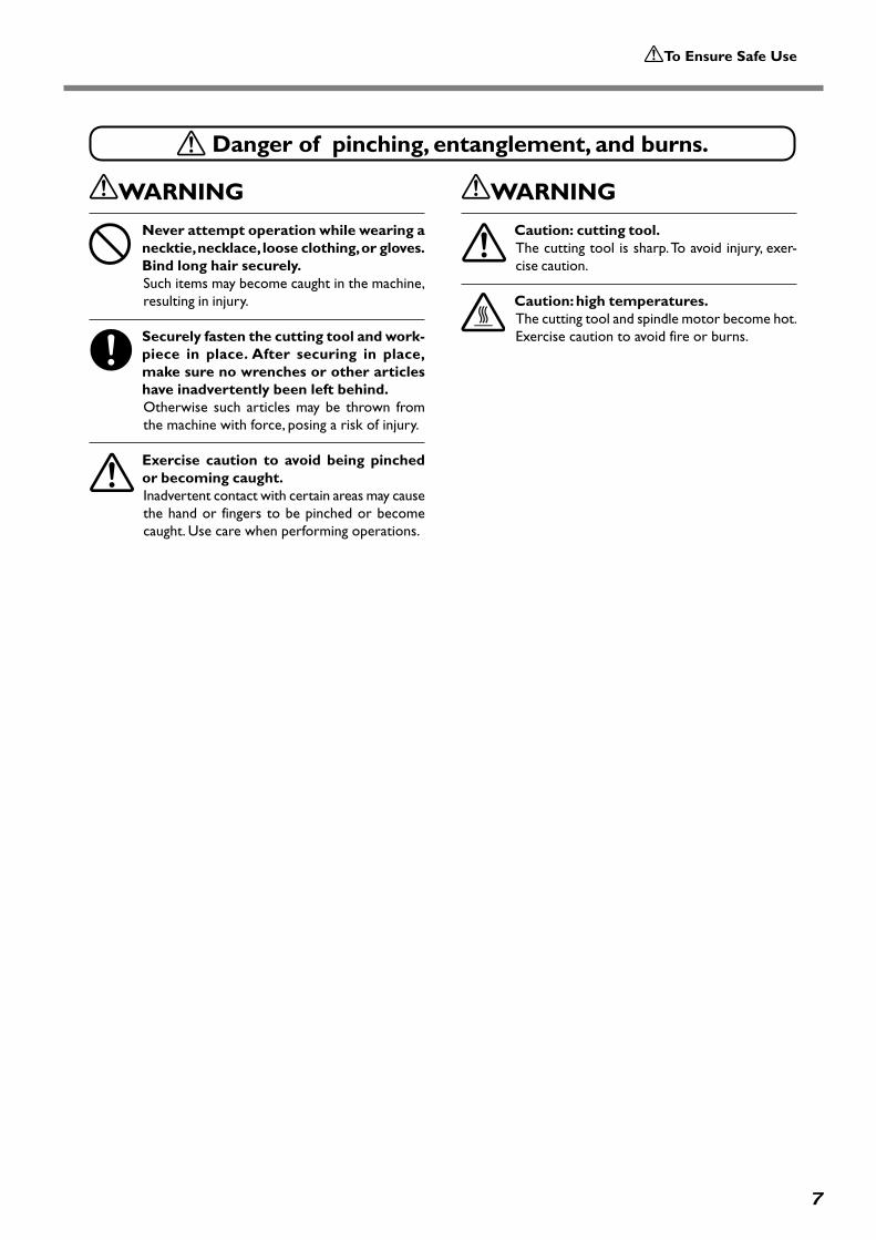
Danger of pinching, entanglement, and burns.
WARNING
Never attempt operation while wearing anecktie, necklace, loose clothing, or gloves.Bind long hair securely.Such items may become caught in the machine,resulting in injury.
Securely fasten the cutting tool and work-piece in place. After securing in place,make sure no wrenches or other articleshave inadvertently been left behind.Otherwise such articles may be thrown fromthe machine with force, posing a risk of injury.
Exercise caution to avoid being pinchedor becoming caught.Inadvertent contact with certain areas may causethe hand or fingers to be pinched or becomecaught. Use care when performing operations.
WARNING
Caution: cutting tool.The cutting tool is sharp. To avoid injury, exer-cise caution.
Caution: high temperatures.The cutting tool and spindle motor become hot.Exercise caution to avoid fire or burns.

To Ensure Safe Use
8
WARNING
Connect to an electrical outlet that com-plies with this machine’s ratings (for volt-age and frequency).Provide a power supply whose amperage is 1.3A or higher (for 100 to 120 V) or 0.6 A or higher(for 220 to 240 V).
Never use out of doors or in any locationwhere exposure to water or high humid-ity may occur. Never touch with wet hands.Doing so may result in fire or electrical shock.
Never allow any foreign object to get in-side. Never expose to liquid spills.Inserting objects such as coins or matches orallowing beverages to be spilled into the venti-lation ports may result in fire or electrical shock.If anything gets inside, immediately disconnectthe power cord and contact your authorizedRoland DG Corp. dealer.
Never place any flammable object nearby.Never use a combustible aerosol spraynearby. Never use in any location wheregases can accumulate.Combustion or explosion may be a danger.
Handle the power cord, plug, and electri-cal outlet correctly and with care. Neveruse any article that is damaged.Using a damaged article may result in fire orelectrical shock.
Danger of electrical short, shock, electrocution, or fire
WARNING
When using an extension cord or powerstrip, use one that adequately satisfies themachine’s ratings (for voltage, frequency,and current).Use of multiple electrical loads on a single elec-trical outlet or of a lengthy extension cord maycause fire.
When the machine will be out of use for aprolonged period, disconnect the powercord.This can prevent accidents in the event of cur-rent leakage or unintended startup.
Connect to ground.This can prevent fire or electrical shock due tocurrent leakage in the event of malfunction.
Position so that the power plug is withinimmediate reach at all times.This is to enable quick disconnection of thepower plug in the event of an emergency. Installthe machine next to an electrical outlet. Also,provide enough empty space to allow immedi-ate access to the electrical outlet.
Never use cutting oil.This machine is not designed for the flow ofcutting oil. Oil may get inside the machine andcause fire or electrical shock.
Never use a pneumatic blower.This machine is not compatible with a pneumaticblower. Cutting waste may get inside the ma-chine and cause fire or electrical shock.
If sparking, smoke, burning odor, unusualsound, or abnormal operation occurs, im-mediately unplug the power cord. Neveruse if any component is damaged.Continuing to use the machine may result in fire,electrical shock, or injury. Contact your autho-rized Roland DG Corp. dealer.
Ratings

To Ensure Safe Use
9
Important notes about the power cord, plug, and electrical outlet
Never place any object on top or subject todamage.
Never bend or twist with undue force.
Never pull with undue force.
Never bundle, bind, or roll up.
Never allow to get wet.
Never make hot.
Dust may cause fire.
To Ensure Safe Use
10
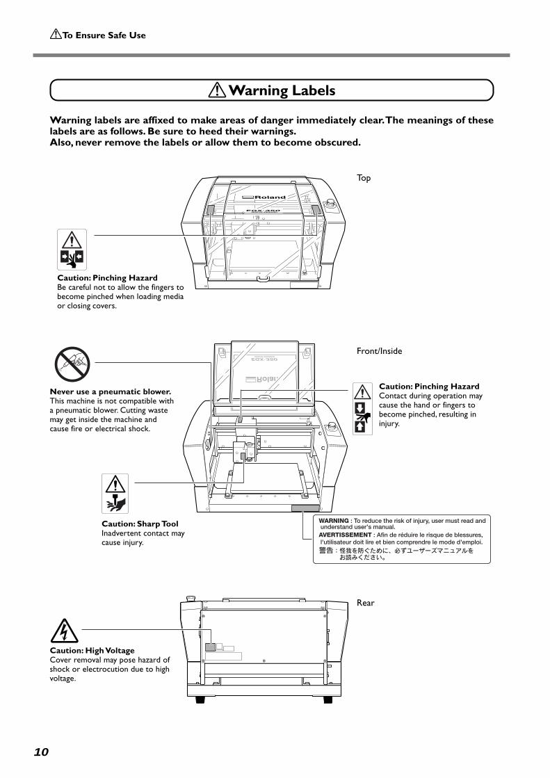
Caution: Sharp ToolInadvertent contact maycause injury.
Caution: Pinching HazardBe careful not to allow the fingers tobecome pinched when loading mediaor closing covers.
Never use a pneumatic blower.This machine is not compatible witha pneumatic blower. Cutting wastemay get inside the machine andcause fire or electrical shock.
Caution: High VoltageCover removal may pose hazard ofshock or electrocution due to highvoltage.
Rear
Front/Inside
Caution: Pinching HazardContact during operation maycause the hand or fingers tobecome pinched, resulting ininjury.
Top
Warning labels are affixed to make areas of danger immediately clear. The meanings of theselabels are as follows. Be sure to heed their warnings.Also, never remove the labels or allow them to become obscured.
Warning Labels

11
Pour utiliser en toute sécurité
La manipulation ou l'utilisation inadéquates de cet appareil peuvent causer des blessures oudes dommages matériels. Les précautions à prendre pour prévenir les blessures ou les dommagessont décrites ci-dessous.
Utilisé pour avertir l'utilisateur d'un risque de décès ou de blessure grave encas de mauvaise utilisation de l'appareil.
Avis sur les avertissements
Utilisé pour avertir l'utilisateur d'un risque de blessure ou de dommage matérielen cas de mauvaise utilisation de l'appareil.
* Par dommage matériel, il est entendu dommage ou tout autre effetindésirable sur la maison, tous les meubles et même les animauxdomestiques.
ATTENTION
PRUDENCE
Le symbole attire l'attention de l'utilisateur sur les instructions importantes ou lesavertissements. Le sens précis du symbole est déterminé par le dessin à l'intérieur du triangle.Le symbole à gauche signifie "danger d'électrocution."
Le symbole avertit l'utilisateur de ce qu'il ne doit pas faire, ce qui est interdit. La chosespécifique à ne pas faire est indiquée par le dessin à l'intérieur du cercle. Le symbole à gauchesignifie que l'appareil ne doit jamais être démonté.
Le symbole prévient l'utilisateur sur ce qu'il doit faire. La chose spécifique à faire est indiquéepar le dessin à l'intérieur du cercle. Le symbole à gauche signifie que le fil électrique doit êtredébranché de la prise.
À propos des symboles

Pour utiliser en toute sécurité
12
L’utilisation incorrecte peut causer des blessures
ATTENTION
S’assurer de suivre les procéduresd’utilisation décrites dans la documenta-tion. Ne jamais permettre à quiconque neconnaît pas le fonctionnement ou lamanutention de l’appareil de le toucher.L’utilisation ou la manutention incorrectespeuvent causer un accident.
Garder les enfants loin de l’appareil.L’appareil comporte des zones et descomposants qui présentent un danger pour lesenfants et qui pourraient causer des blessures,la cécité, la suffocation ou d’autres accidentsgraves.
Ne jamais faire fonctionner l’appareilaprès avoir consommé de l’alcool ou desmédicaments, ou dans un état de fatigue.L’utilisation de l’appareil exige un jugement sansfaille. L’utilisation avec les facultés affaibliespourrait entraîner un accident.
Utiliser l’appareil dans un endroit propreet bien éclairé.Travailler dans un endroit sombre ou encombrépeut causer un accident; l’utilisateur risque, parexemple, de trébucher malencontreusement etd’être coincé par une partie de l’appareil.
Ne jamais utiliser l’appareil à des finsautres que celles pour lesquelles il estconçu. Ne jamais l’utiliser de manière abu-sive ou d’une manière qui dépasse sacapacité.Le non-respect de cette consigne peut causerdes blessures ou un incendie.
Ne jamais utiliser un outil de coupeémoussé. Procéder fréquemment auxtravaux d’entretien pour garder l’appareilen bon état de fonctionnement.L’usage abusif peut causer un incendie ou desblessures.
Utiliser uniquement des accessoiresd’origine (accessoires en option, articlesconsommables, câble d’alimentation etautres articles semblables), compatiblesavec l’appareil.Les articles incompatibles risquent de causer desaccidents.
ATTENTION
Débrancher le câble d’alimentation avantde procéder au nettoyage ou à l’entretiende l’appareil, et avant d’y fixer ou d’enretirer des accessoires en option.Tenter ces opérations pendant que l’appareil estbranché à une source d’alimentation peut causerdes blessures ou un choc électrique.
Ne jamais tenter de démonter, de réparerou de modifier l’appareil.Le non-respect de cette consigne risque deprovoquer un incendie, un choc électrique oudes blessures. Confier les réparations à untechnicien ayant la formation requise.
PRUDENCE
Ne jamais grimper ni s’appuyer sur lamachine.La machine n’est pas conçue pour supporter lepoids d’une personne. Grimper ou s’appuyer surla machine peut déplacer des éléments et causerun faux pas ou une chute, ce qui causerait desblessures.

Pour utiliser en toute sécurité
13
Le poids de cet appareil est de 34 kg (75 lb.)
PRUDENCE
Le déchargement et la mise en placedoivent être faits par au moins 2personnes.Les tâches qui exigent un effort trop grand sielles sont exécutées par un petit nombre depersonnes peuvent être cause de blessures. Lachute d’articles très lourds peut aussi causer desblessures.
PRUDENCE
Installer l’appareil à un endroit stable etplat.Installer l’appareil à un endroit inapproprié peutprovoquer un accident grave comme lerenversement ou la chute.
ATTENTION
Ne jamais tenter de couper du magnésiumni aucun autre matériau inflammable.Un incendie pourrait se produire pendant lacoupe.
Ne pas approcher une flamme nue del’espace de travail.Les rognures de coupe peuvent s’enflammer. Lesmatériaux pulvérisés sont extrêmementinflammables et même le métal peut s’enflammer.
Si un aspirateur est utilisé pour ramasserles rognures de coupe, faire preuve de pru-dence pour empêcher que la poussières’enflamme ou explose.Ramasser des rognures fines à l’aide d’unaspirateur ordinaire peut créer un risqued’incendie ou d’explosion. Vérifier auprès dufabricant de l’aspirateur. Dans les cas où il estimpossible de déterminer si un aspirateur peutêtre utilisé sans danger, se servir d’une brosseou d’un article semblable plutôt que d’unaspirateur.
PRUDENCE
Porter des lunettes de protection et unmasque. Rincer toutes les rognures decoupe qui pourraient rester collées auxmains.Avaler ou respirer accidentellement desrognures de coupe peut être dangereux pour lasanté.
Les débris de coupe peuvent s ’enflammer ou présenter unrisque pour la santé.
Pour utiliser en toute sécurité
14
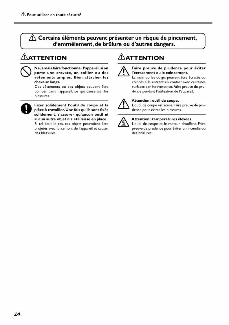
Certains éléments peuvent présenter un risque de pincement,d’emmêlement, de brûlure ou d’autres dangers.
ATTENTION
Ne jamais faire fonctionner l’appareil si onporte une cravate, un collier ou desvêtements amples. Bien attacher lescheveux longs.Ces vêtements ou ces objets peuvent êtrecoincés dans l’appareil, ce qui causerait desblessures.
Fixer solidement l’outil de coupe et lapièce à travailler. Une fois qu’ils sont fixéssolidement, s’assurer qu’aucun outil niaucun autre objet n’a été laissé en place.Si tel était le cas, ces objets pourraient êtreprojetés avec force hors de l’appareil et causerdes blessures.
ATTENTION
Faire preuve de prudence pour éviterl’écrasement ou le coincement.La main ou les doigts peuvent être écrasés oucoincés s’ils entrent en contact avec certainessurfaces par inadvertance. Faire preuve de pru-dence pendant l’utilisation de l’appareil.
Attention : outil de coupe.L’outil de coupe est acéré. Faire preuve de pru-dence pour éviter les blessures.
Attention : températures élevées.L’outil de coupe et le moteur chauffent. Fairepreuve de prudence pour éviter un incendie oudes brûlures.
Pour utiliser en toute sécurité
15
ATTENTION
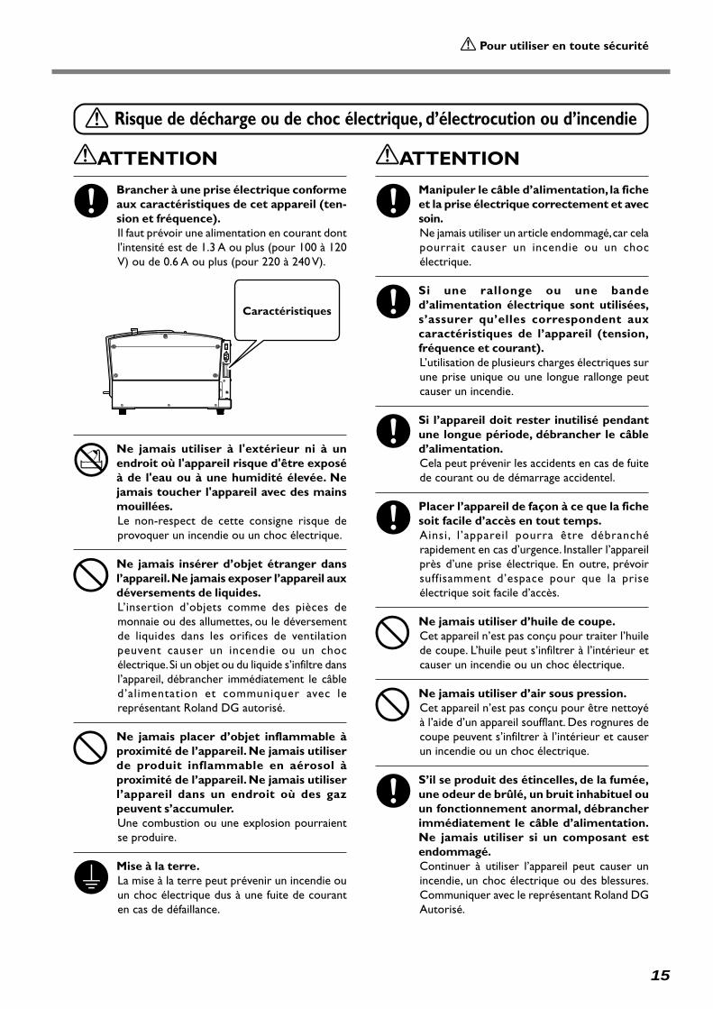
Brancher à une prise électrique conformeaux caractéristiques de cet appareil (ten-sion et fréquence).Il faut prévoir une alimentation en courant dontl'intensité est de 1.3 A ou plus (pour 100 à 120V) ou de 0.6 A ou plus (pour 220 à 240 V).
Ne jamais utiliser à l'extérieur ni à unendroit où l'appareil risque d'être exposéà de l'eau ou à une humidité élevée. Nejamais toucher l'appareil avec des mainsmouillées.Le non-respect de cette consigne risque deprovoquer un incendie ou un choc électrique.
Ne jamais insérer d’objet étranger dansl’appareil. Ne jamais exposer l’appareil auxdéversements de liquides.L’insertion d’objets comme des pièces demonnaie ou des allumettes, ou le déversementde liquides dans les orifices de ventilationpeuvent causer un incendie ou un chocélectrique. Si un objet ou du liquide s’infiltre dansl’appareil, débrancher immédiatement le câbled’alimentation et communiquer avec lereprésentant Roland DG autorisé.
Ne jamais placer d’objet inflammable àproximité de l’appareil. Ne jamais utiliserde produit inflammable en aérosol àproximité de l’appareil. Ne jamais utiliserl’appareil dans un endroit où des gazpeuvent s’accumuler.Une combustion ou une explosion pourraientse produire.
Mise à la terre.La mise à la terre peut prévenir un incendie ouun choc électrique dus à une fuite de couranten cas de défaillance.
Risque de décharge ou de choc électrique, d’électrocution ou d’incendie
ATTENTION
Manipuler le câble d’alimentation, la ficheet la prise électrique correctement et avecsoin.Ne jamais utiliser un article endommagé, car celapourrait causer un incendie ou un chocélectrique.
Si une rallonge ou une banded’alimentation électrique sont utilisées,s’assurer qu’elles correspondent auxcaractéristiques de l’appareil (tension,fréquence et courant).L’utilisation de plusieurs charges électriques surune prise unique ou une longue rallonge peutcauser un incendie.
Si l’appareil doit rester inutilisé pendantune longue période, débrancher le câbled’alimentation.Cela peut prévenir les accidents en cas de fuitede courant ou de démarrage accidentel.
Placer l’appareil de façon à ce que la fichesoit facile d’accès en tout temps.Ainsi, l ’appareil pourra être débranchérapidement en cas d’urgence. Installer l’appareilprès d’une prise électrique. En outre, prévoirsuffisamment d’espace pour que la priseélectrique soit facile d’accès.
Ne jamais utiliser d’huile de coupe.Cet appareil n’est pas conçu pour traiter l’huilede coupe. L’huile peut s’infiltrer à l’intérieur etcauser un incendie ou un choc électrique.
Ne jamais utiliser d’air sous pression.Cet appareil n’est pas conçu pour être nettoyéà l’aide d’un appareil soufflant. Des rognures decoupe peuvent s’infiltrer à l’intérieur et causerun incendie ou un choc électrique.
S’il se produit des étincelles, de la fumée,une odeur de brûlé, un bruit inhabituel ouun fonctionnement anormal, débrancherimmédiatement le câble d’alimentation.Ne jamais utiliser si un composant estendommagé.Continuer à utiliser l’appareil peut causer unincendie, un choc électrique ou des blessures.Communiquer avec le représentant Roland DGAutorisé.
Caractéristiques

Pour utiliser en toute sécurité
16
Remarques importantes à propos du câble d'alimentation, de la fiche et de la prise électrique
Ne jamais déposer aucun objet sur le câble, sur la ficheou sur la prise car cela risque de les endommager.
Ne jamais plier ni tordre le câble avec uneforce excessive.
Ne jamais tirer sur le câble ou la fiche avecune force excessive.
Ne jamais plier ni enrouler le câble.
Ne jamais laisser l'eau toucher le câble, lafiche ou la prise.
Ne jamais chauffer le câble, la fiche ou laprise.
La poussière peut causer un incendie.

Pour utiliser en toute sécurité
17
Attention : outil coupantUn contact imprudentrisque d’entraîner uneblessure.
Attention : Risque de pincementFaire attention de ne pas coincer lesdoigts pendant le chargement dusupport ou lors de la fermeture ducouvercle.
Ne jamais utiliser d’air souspression.Cet appareil n’est pas conçu pourêtre nettoyé à l’aide d’un appareilsoufflant. Des rognures de coupepeuvent s’infiltrer à l’intérieur etcauser un incendie ou un chocélectrique.
Attention : voltage élevéIl peut être dangereux de retirer lecouvercle puisqu’il y aurait des risquesde chocs électriques oud’électrocution à cause du voltageélevé.
Arrière
Avant/intérieur
Attention : risque depincementUn contact pendant lefonctionnement peutcoincer la main ou lesdoigts ce qui risque decauser des blessures.
Haut
Des vignettes d'avertissement sont apposées pour qu'il soit facile de repérer les zonesdangereuses. La signification des vignettes est donnée ci-dessous. Respecter les avertissements.Ne jamais retirer les vignettes et ne pas les laisser s'encrasser.
Vignettes d'avertissement

18
Important Notes on Handling and Use
This machine is a precision device. To ensure the full performance of this machine, be sure to observe thefollowing important points. Failure to observe these may not only result in loss of performance, but may alsocause malfunction or breakdown.
This machine is a precision device.
➢Handle carefully, and never subject the machine to impact or excessive force.➢Use within the range of specifications.➢Diligently keep clean of cutting waste.➢Never needlessly touch anywhere inside the machine except for locations specified in this manual.
Install in a suitable location.
➢ Install in a location that meets the specified conditions for temperature, relative humidity, and the like.➢ Install in a quiet, stable location offering good operating conditions.➢Never install in out of doors.
This machine becomes hot.
➢Never cover the ventilation holes with cloth, tape, or anything else.➢ Install in a well-ventilated location.
About Cutters
➢Use a cutter that is suitable for the workpiece and the cutting method.➢The tip of the cutter is breakable. Handle with care, being careful not to drop it.

19
About the Documentation for This Machine
Documentation Included with the Machine
The following documentation is included with the machine.
User's Manual (this manual)This describes important notes for ensuring safe use, and explains how to install and operate the machine. Besure to read it first.It does not describe how to operate your computer or how to use the programs.
Roland Software Package Software GuideThis explains how to install included program and other software and details.Be sure to read this, when connecting the machine to a computer.
Roland EngraveStudio Software GuideThis explains how to install included program and other software and details.
Dr. Engrave User's Manual (electronic-format manual)This manual explains how to use the included engraving program. It describes procedures ranging from how todesign a nameplate or the like to engraving operations. Read it if you're using this program.The manual is in electronic format, and no printed document is included. You can find it on the included RolandSoftware Package CD-ROM.
3D Engrave User's Manual (electronic-format manual)This manual explains how to use the included program for three-dimensional engraving and for creating reliefs.It describes procedures ranging from how to design reliefs and the like to cutting operations. Read it if you'reusing this program.The manual is in electronic format, and no printed document is included. You can find it on the included RolandSoftware Package CD-ROM.
EngraveStudio User's Manual (electronic-format manual)This is the documentation for using the included three-dimensional (relief) engraving program. It describes thesteps from designing text and shapes to engrave on wooden signs and the like through to the engraving opera-tions. Read it if you're using this program.The manual is in electronic format, and no printed document is included. You can find it on the included RolandEngraveStudio CD-ROM.
Virtual MODELA User's Manual (electronic-format manual)This is the documentation for a program that creates previews by simulating cutting using 3D Engrave. It de-scribes all the steps from receiving data created using 3D Engrave to simulation of cutting operations. Read it ifyou're using this program.The manual is in electronic format, and no printed document is included. You can find it on the included RolandSoftware Package CD-ROM.

20

21
Chapter 1Getting Started
22 Chapter 1 Getting Started
1-1 Machine Highlights
Features
➢ Engraving and relief-cutting on a single machineThis machine achieves expressive, high-quality engraving of a wide range of types, from flat engraving to three-dimensional reliefs.
➢ Outstanding basic performanceThe spacious operating area measuring 40 millimeters high by 305 millimeters wide by 230 millimeters deep and thehigh-speed spindle that turns at up to 20,000 rpm make for rapid engraving. Workpieces up to 40 millimeters thick canbe accommodated.
➢ Accommodates a wide variety of engraving materialsThe machine can engrave a wide range of workpiece materials, from plastics, acrylics, and other resin-based materialsto light metals such as aluminum and brass.
➢ Designed for ease of useYou control machine operation using a handy panel that is separate from the machine. This lets you control themachine from a location affording a clear view of the workpiece and tool. You can also make the settings for themachine simply and easily while viewing the display screen on the handy panel.
➢ Automatic Z control featureThe machine offers an automatic Z control feature that makes possible engraving at a uniform depth, even on workpieceswith wavy surfaces.(Trackable undulation height: gentle undulations of about 1 millimeter)
➢ High levels of safetyA front cover and an emergency-stop button are standard features of the machine.
23Chapter 1 Getting Started
1-2 Part Names and Functions
Front and Interior
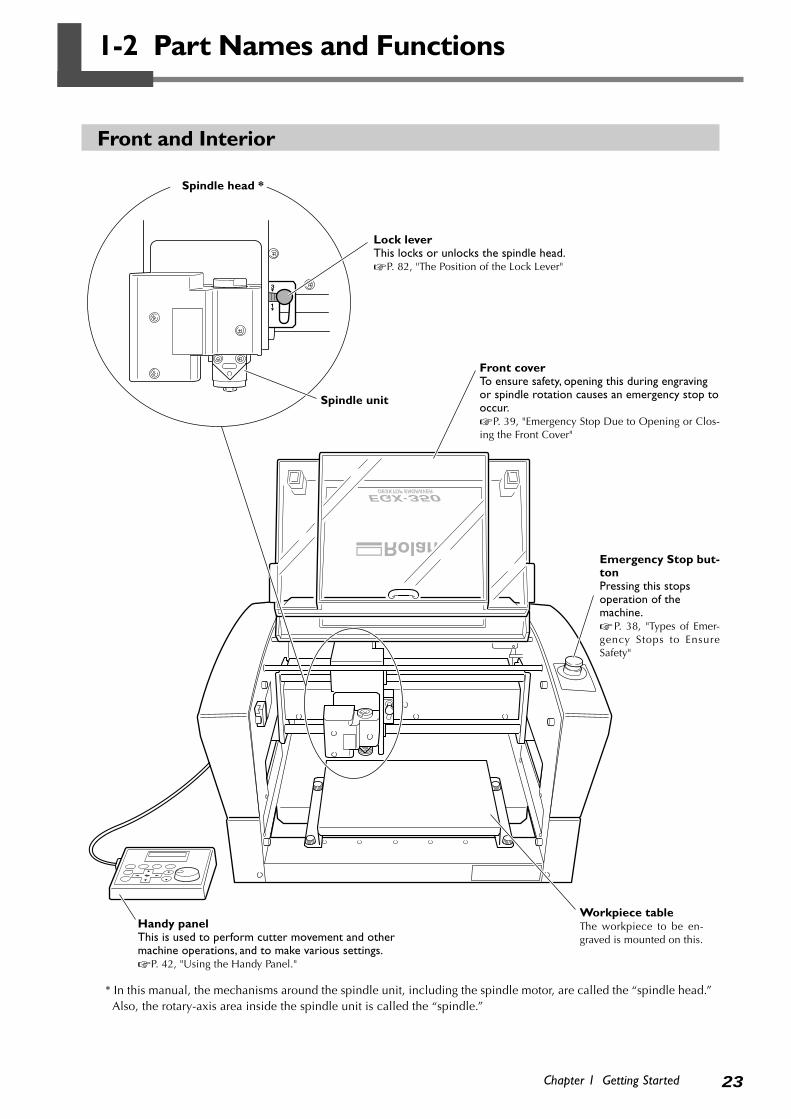
Emergency Stop but-tonPressing this stopsoperation of themachine.☞ P. 38, "Types of Emer-gency Stops to EnsureSafety"
Front coverTo ensure safety, opening this during engravingor spindle rotation causes an emergency stop tooccur.☞ P. 39, "Emergency Stop Due to Opening or Clos-ing the Front Cover"
Handy panelThis is used to perform cutter movement and othermachine operations, and to make various settings.☞ P. 42, "Using the Handy Panel."
Workpiece tableThe workpiece to be en-graved is mounted on this.
Lock leverThis locks or unlocks the spindle head.☞ P. 82, "The Position of the Lock Lever"
* In this manual, the mechanisms around the spindle unit, including the spindle motor, are called the “spindle head.” Also, the rotary-axis area inside the spindle unit is called the “spindle.”
Spindle unit
Spindle head *

1-2 Part Names and Functions
24 Chapter 1 Getting Started
Side
Right side
Left side
Power switch
Power-cord connector
Expansion portThis is a connector for external equipment.☞ P. 111, “Expansion Connector”
Serial connectorThis is for connecting a serial (RS-232C-compliant) cable.☞ P. 32, “Connecting a Computer Via a Com-munication Cable”
USB connectorThis is for connecting a USB cable.☞ P. 32, “Connecting a Computer Viaa Communication Cable”
Handy-panel connectorThis is for connecting the handy panel.☞ P. 30, “Connecting the Handy Panel”
25
Chapter 2Installation and Setup
26 Chapter 2 Installation and Setup
2-1 Checking the Included Items
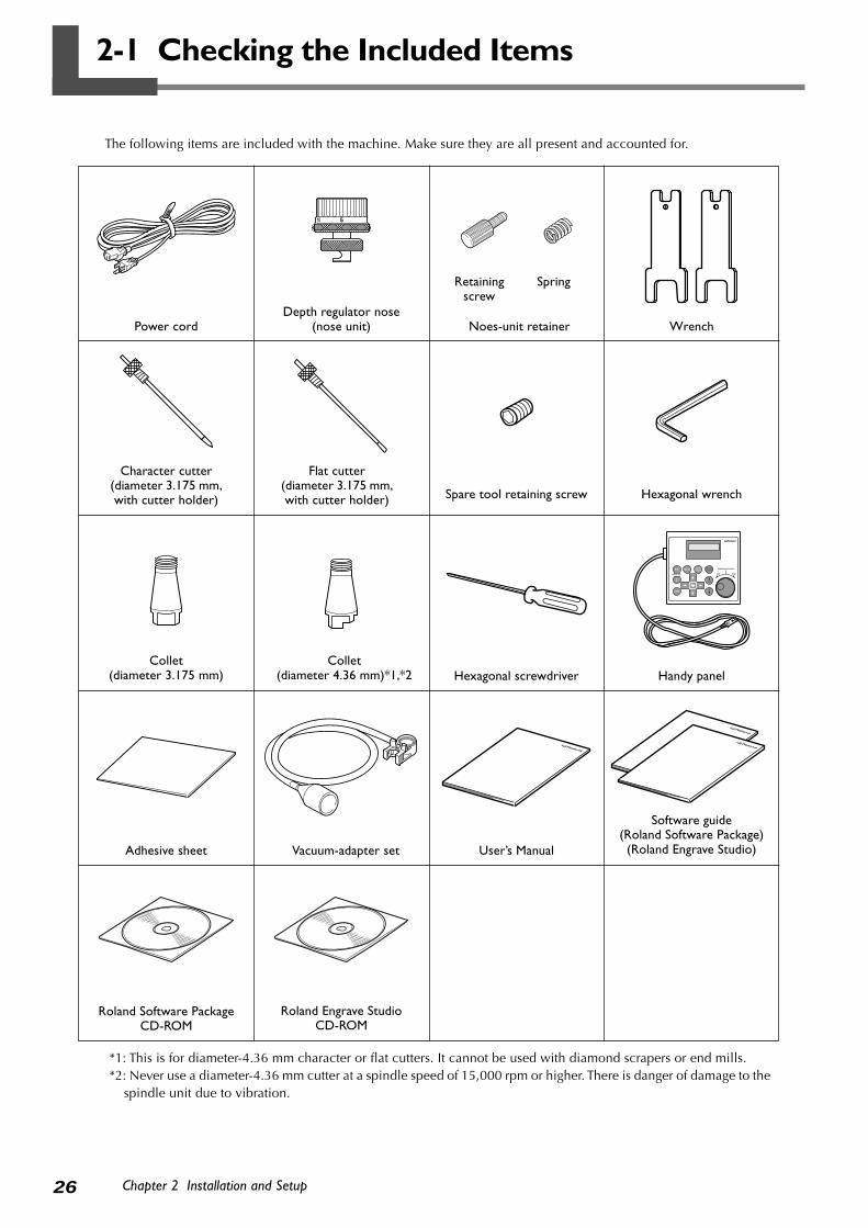
The following items are included with the machine. Make sure they are all present and accounted for.
Retainingscrew
Spring
Noes-unit retainer
Roland Engrave StudioCD-ROM
*1: This is for diameter-4.36 mm character or flat cutters. It cannot be used with diamond scrapers or end mills.*2: Never use a diameter-4.36 mm cutter at a spindle speed of 15,000 rpm or higher. There is danger of damage to the
spindle unit due to vibration.
Power cord
Software guide(Roland Software Package)(Roland Engrave Studio)
Depth regulator nose(nose unit)
Spare tool retaining screw
Character cutter(diameter 3.175 mm,with cutter holder)
Flat cutter(diameter 3.175 mm,with cutter holder)
Wrench
Collet(diameter 3.175 mm)
Collet(diameter 4.36 mm)*1,*2 Hexagonal screwdriver
Hexagonal wrench
Handy panel
Adhesive sheet Vacuum-adapter set User’s Manual
Roland Software PackageCD-ROM

27Chapter 2 Installation and Setup
2-2 Installation
About Emplacement and Installation
WARNING Unloading and emplacement are operations that must be performed by 2 personsor more.Tasks that require undue effort when performed by a small number of persons may resultin physical injury. Also, if dropped, such items may cause injury.
The weight of the machine alone is 34 kg (75 lb.). Perform unloading and emplacement with care.
Installation Environment
Install in a quiet, stable location offering good operating conditions. An unsuitable location can cause accident, fire,faulty operation, or breakdown.
WARNING Install in a location that is level and stable.Installation in an unsuitable location may cause an accident, including a fall or tipover.
WARNING Never install in a location exposed to open flame.Cutting waste may ignite. Powdered material is extremely flammable, and even metalmaterial may catch fire.
WARNING Never install close to any flammable object or in a gas-filled location.Combustion or explosion may be a danger.
WARNING Never install out of doors or in any location where exposure to water or highhumidity may occur.Doing so may result in fire or electrical shock.
WARNING Position so that the power plug is within immediate reach at all times.This is to enable quick disconnection of the power plug in the event of an emergency.Install the machine next to an electrical outlet. Also, provide enough empty space to allowimmediate access to the electrical outlet.
➢ Never install in a location subject to wide fluctuations in temperature or humidity.➢ Never install in a location subject to shaking or vibration.➢ Never install in a locations where the floor is tilted, not level, or unstable.➢ Never install in a dusty or dirty location, or out of doors.➢ Never install in a location exposed to direct sunlight or near air-conditioning or heating equipment.➢ Never install in a location exposed to considerable electrical or magnetic noise, or other forms of electromagnetic
energy.

2-2 Installation
28 Chapter 2 Installation and Setup
Installation Space
Ensure that at least the following amount of space is available.
Height of Installation
The height of installation should be 0.6 m (23.7 in.) or higher above the work floor.This machine is desktop type. Please decide the height of installation so that you can easily reach the emergency stopbutton when operating this machine.
Installation space
Work space
1.0 m (3.3 ft.)
1.0
m (
3.3
ft.)
2.0
m (
6.6
ft.)
2.0 m (6.6 ft.)
2-2 Installation
29Chapter 2 Installation and Setup
Unpacking
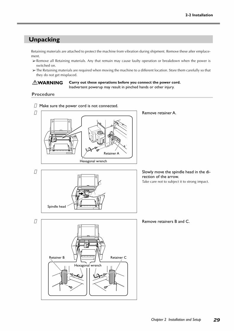
Retaining materials are attached to protect the machine from vibration during shipment. Remove these after emplace-ment.➢ Remove all Retaining materials. Any that remain may cause faulty operation or breakdown when the power is
switched on.➢ The Retaining materials are required when moving the machine to a different location. Store them carefully so that
they do not get misplaced.
WARNING Carry out these operations before you connect the power cord.Inadvertent powerup may result in pinched hands or other injury.
Procedure
➊ Make sure the power cord is not connected.
➋ Remove retainer A.
➌ Slowly move the spindle head in the di-rection of the arrow.Take care not to subject it to strong impact.
➍ Remove retainers B and C.
Spindle head
Retainer A
Retainer B Retainer C
Hexagonal wrench
Hexagonal wrench

30 Chapter 2 Installation and Setup
2-3 Cable Connections
Connecting the Handy Panel
Make sure the power to the machine is switched off before attempting to connect or disconnect cables.Connecting the handy panel while the power is on makes the handy panel unusable.
Insert fully andsecurely.
Handy panel
Left side
Cable clamp
2-3 Cable Connections
31Chapter 2 Installation and Setup
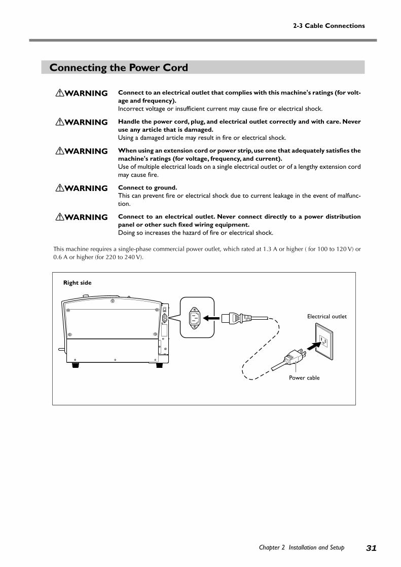
Connecting the Power Cord
WARNING Connect to an electrical outlet that complies with this machine's ratings (for volt-age and frequency).Incorrect voltage or insufficient current may cause fire or electrical shock.
WARNING Handle the power cord, plug, and electrical outlet correctly and with care. Neveruse any article that is damaged.Using a damaged article may result in fire or electrical shock.
WARNING When using an extension cord or power strip, use one that adequately satisfies themachine's ratings (for voltage, frequency, and current).Use of multiple electrical loads on a single electrical outlet or of a lengthy extension cordmay cause fire.
WARNING Connect to ground.This can prevent fire or electrical shock due to current leakage in the event of malfunc-tion.
WARNING Connect to an electrical outlet. Never connect directly to a power distributionpanel or other such fixed wiring equipment.Doing so increases the hazard of fire or electrical shock.
This machine requires a single-phase commercial power outlet, which rated at 1.3 A or higher ( for 100 to 120 V) or0.6 A or higher (for 220 to 240 V).
Right side
Power cable
Electrical outlet

2-3 Cable Connections
32 Chapter 2 Installation and Setup
Connecting a Computer Via a Communication Cable
USB cable
At this time, keep the cable unconnected until you carry out this operation.Follow the instructions in the separate Roland Software Package Software Guide to make the connection.
☞ P. 19, "About the Documentation for This Machine"
➢Never connect two or more machines to one computer.➢Use a shielded USB cable having a length of 3 m (10 ft.) or less.➢Never use a USB hub.
Serial cable
Using a serial cable requires making the settings for the communication parameters with the computer.For the serial cable, use a separately available XY-RS-34 from Roland DG Corp.
☞ P. 85, "Submenus," p. 110, "Serial Connector"
At this time, keep the cable un-connected until you carry outthis operation.
USB cable
ComputerUSB port
Serial cableComputer
Left side
Left side
Secure in place with the screws.
RS-232C connector
33Chapter 2 Installation and Setup
2-4 Selecting the Language
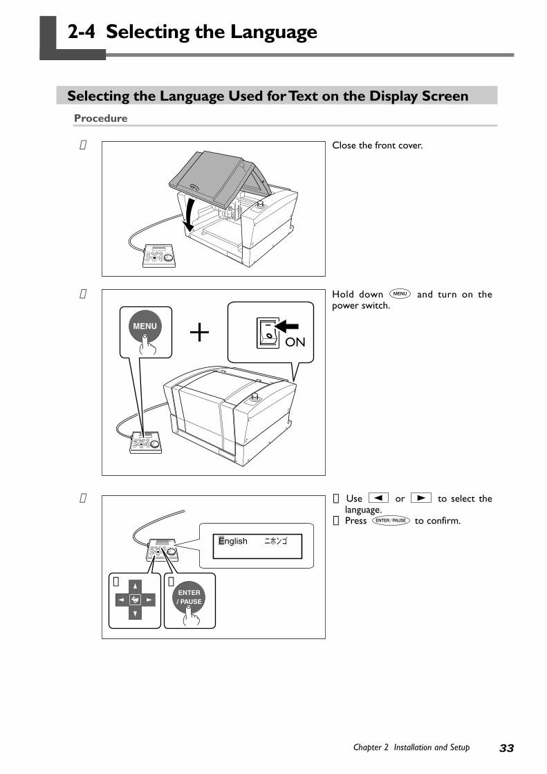
Selecting the Language Used for Text on the Display ScreenProcedure
➊ Close the front cover.
➋ Hold down and turn on thepower switch.
➌ ➀ Use or to select thelanguage.
➁ Press to confirm.
ON
➀ ➁

2-4 Selecting the Language
34 Chapter 2 Installation and Setup
➍ Switch off the power switch.
OFF

35Chapter 2 Installation and Setup
2-5 Before Starting Operations
Spindle Run-in (Warm-up)
In any of the following cases, perform run-in (warm-up) operation for the spindle. Failure to do so may result inunstable spindle rotation.
➢ When using for the first time after purchase➢ After moving the machine and reinstalling it at a different location➢ After replacing the spindle unit➢ When using in a low-temperature environment
How to Perform Run-in (Warm-up) OperationCarry out the following steps 1 through 4.
☞ P. 47, “Starting and Stopping Spindle Rotation”
Step 1Speed : 5,000 rpmRotation time : 15 minutes
Step 2Speed : 10,000 rpmRotation time : 10 minutes
Step 3Speed : 15,000 rpmRotation time : 10 minutes
Step 4Speed : 20,000 rpmRotation time : 15 minutes

36

37
Chapter 3Basic Operation
38 Chapter 3 Basic Operation
3-1 Types of Emergency Stops to Ensure Safety
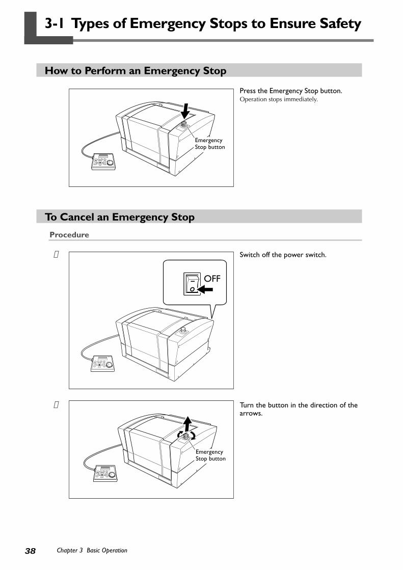
How to Perform an Emergency Stop
Press the Emergency Stop button.Operation stops immediately.
To Cancel an Emergency Stop
Procedure
➊ Switch off the power switch.
➋ Turn the button in the direction of thearrows.
EmergencyStop button
OFF
EmergencyStop button

3-1 Types of Emergency Stops to Ensure Safety
39Chapter 3 Basic Operation
Emergency Stop Due to Opening or Closing the Front Cover
To ensure safety, opening the front cover during engraving or spindle rotation causes an emergency stop to occur, andthe message shown below appears on the display screen. Operation cannot be resumed by closing the front cover. Toresume, switch off the power, then start up again.
☞ P. 40, “Starting and Quitting”
Front cover
40 Chapter 3 Basic Operation
3-2 Starting and Quitting
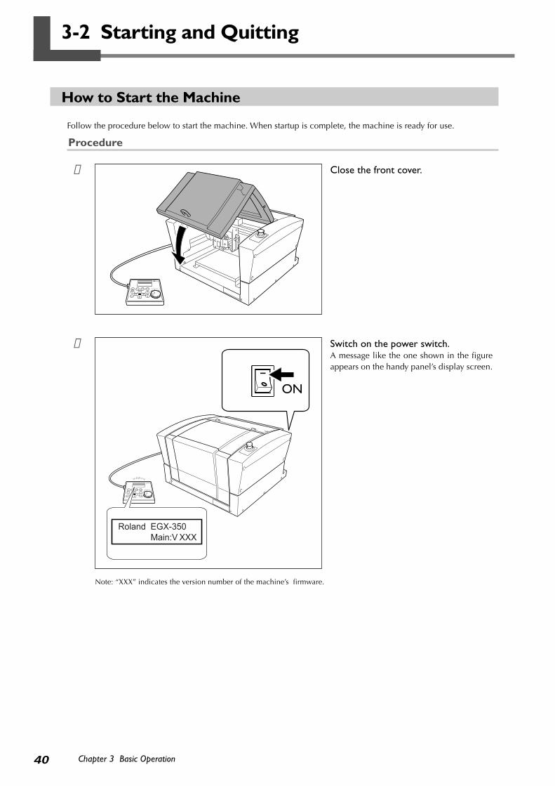
How to Start the Machine
Follow the procedure below to start the machine. When startup is complete, the machine is ready for use.
Procedure
➊ Close the front cover.
➋ Switch on the power switch.A message like the one shown in the figureappears on the handy panel’s display screen.
ON
Note: “XXX” indicates the version number of the machine’s firmware.

3-2 Starting and Quitting
41Chapter 3 Basic Operation
➌ When the screen shown in the figure at left appears afterapproximately three seconds, press .The spindle head moves to a location on the inner-left side of themachine. This operation is called “initialization.”The default for the language used for on-screen display is English.To change the display language to Japanese, refer to the page indi-cated below and change the language setting.☞ P. 33, "Selecting the Language Used for Text on the Display Screen"
When initialization ends, the screen changes to a display like thatshown at left (the mainscreen). This completes initialization.
Shutdown
Make sure the machine is not in opera-tion, then turn off the power switch.The display screen on the handy panel goesdark.
Dark
OFF
Main screen
42 Chapter 3 Basic Operation
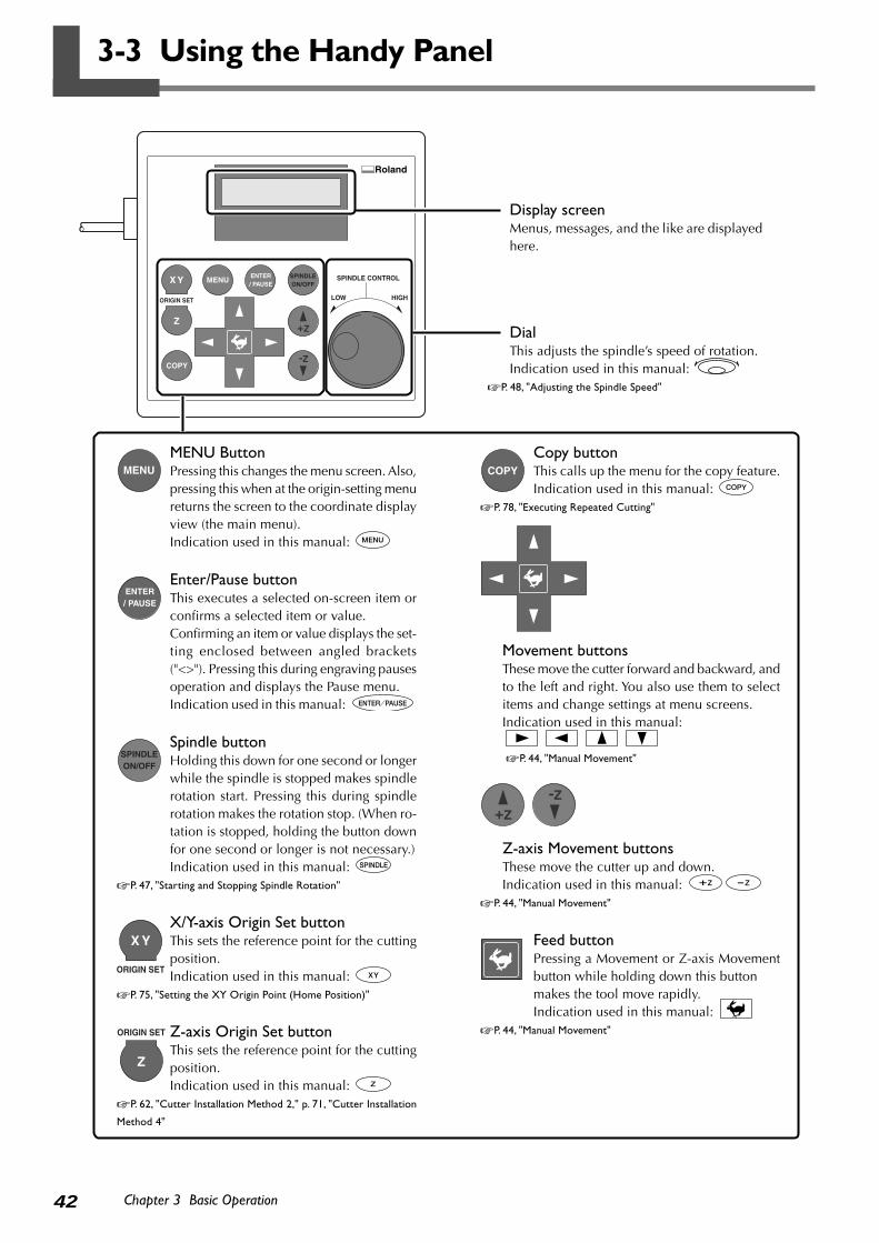
MENU ButtonPressing this changes the menu screen. Also,pressing this when at the origin-setting menureturns the screen to the coordinate displayview (the main menu).Indication used in this manual:
Enter/Pause buttonThis executes a selected on-screen item orconfirms a selected item or value.Confirming an item or value displays the set-ting enclosed between angled brackets("<>"). Pressing this during engraving pausesoperation and displays the Pause menu.Indication used in this manual:
Spindle buttonHolding this down for one second or longerwhile the spindle is stopped makes spindlerotation start. Pressing this during spindlerotation makes the rotation stop. (When ro-tation is stopped, holding the button downfor one second or longer is not necessary.)Indication used in this manual:
☞ P. 47, "Starting and Stopping Spindle Rotation"
X/Y-axis Origin Set buttonThis sets the reference point for the cuttingposition.Indication used in this manual:
☞ P. 75, "Setting the XY Origin Point (Home Position)"
Z-axis Origin Set buttonThis sets the reference point for the cuttingposition.Indication used in this manual:
☞ P. 62, "Cutter Installation Method 2," p. 71, "Cutter Installation
Method 4"
Copy buttonThis calls up the menu for the copy feature.Indication used in this manual:
☞ P. 78, "Executing Repeated Cutting"
Movement buttonsThese move the cutter forward and backward, andto the left and right. You also use them to selectitems and change settings at menu screens.Indication used in this manual:
☞ P. 44, "Manual Movement"
Z-axis Movement buttonsThese move the cutter up and down.Indication used in this manual:
☞ P. 44, "Manual Movement"
Feed buttonPressing a Movement or Z-axis Movementbutton while holding down this buttonmakes the tool move rapidly.Indication used in this manual:
☞ P. 44, "Manual Movement"
3-3 Using the Handy Panel
DialThis adjusts the spindle’s speed of rotation.Indication used in this manual:
☞ P. 48, "Adjusting the Spindle Speed"
Display screenMenus, messages, and the like are displayedhere.
43Chapter 3 Basic Operation
3-4 Moving the Cutter
Terms Indicating the Cutter Position
This manual uses the following terms to indicate the position of the cutter.
➢ CoordinatesNumerical values indicating the location of the cutter
➢ OriginThe point of origin for the coordinates
➢ X-axis coordinateThe distance along the X axis from the origin point
➢ Y-axis coordinateThe distance along the Y axis from the origin point
➢ Z-axis coordinateThe distance along the Z axis from the origin point
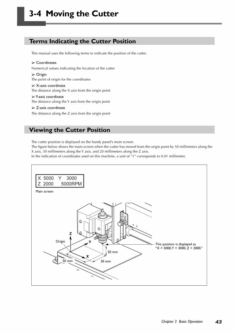
Viewing the Cutter Position
The cutter position is displayed on the handy panel’s main screen.The figure below shows the main screen when the cutter has moved from the origin point by 50 millimeters along theX axis, 30 millimeters along the Y axis, and 20 millimeters along the Z axis.In the indication of coordinates used on this machine, a unit of “1” corresponds to 0.01 millimeter.
This position is displayed as“X = 5000, Y = 3000, Z = 2000.”
30 mm
20 mm
Origin
50 mm
Main screen

3-4 Moving the Cutter
44 Chapter 3 Basic Operation
Manual Movement
When the screen on the handy panel displays any one of the messages shown in the figure below, you can move thecutter manually using the movement buttons.
☞ P. 84, "Menu List"
➢ Each single press of , , , , or performs movement by 0.01 millimeter.
➢ Holding down , , , , or performs slow continuous movement.
➢ Holding down while pressing and holding , , , , or performs rapidcontinuous movement.
Important!
This operation is not possible in the following cases.
➢ When engraving is in progress➢ When operation is paused
-X
-Y
+Z
-Z
+X
+Y
+Y
-Y
+X-X +Z
-Z
Movement along only the Xand Y axes
Movement along all axes(X, Y, and Z)
Movement along only the Zaxis(“XXX” is “DOWN,” “SUR-FACE,” or “UP.”)
Handy panel
Movement buttons
3-4 Moving the Cutter
45Chapter 3 Basic Operation
Moving to a Specific Position AutomaticallyProcedure
➊ Close the front cover.
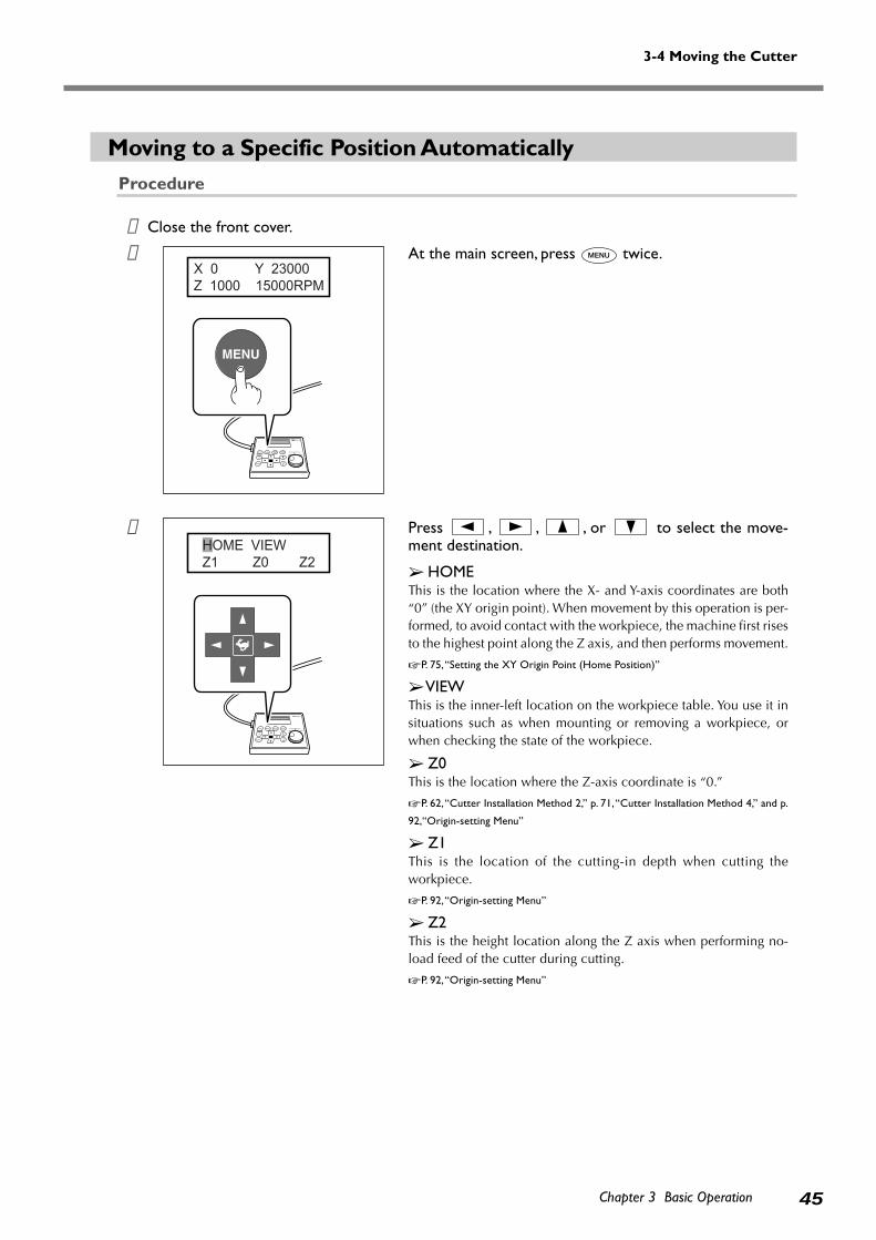
➋ At the main screen, press twice.
➌ Press , , , or to select the move-ment destination.
➢ HOMEThis is the location where the X- and Y-axis coordinates are both“0” (the XY origin point). When movement by this operation is per-formed, to avoid contact with the workpiece, the machine first risesto the highest point along the Z axis, and then performs movement.
☞ P. 75, “Setting the XY Origin Point (Home Position)”
➢ VIEWThis is the inner-left location on the workpiece table. You use it insituations such as when mounting or removing a workpiece, orwhen checking the state of the workpiece.
➢ Z0This is the location where the Z-axis coordinate is “0.”
☞ P. 62, “Cutter Installation Method 2,” p. 71, “Cutter Installation Method 4,” and p.
92,“Origin-setting Menu”
➢ Z1This is the location of the cutting-in depth when cutting theworkpiece.
☞ P. 92, “Origin-setting Menu”
➢ Z2This is the height location along the Z axis when performing no-load feed of the cutter during cutting.
☞ P. 92, “Origin-setting Menu”
3-4 Moving the Cutter
46 Chapter 3 Basic Operation
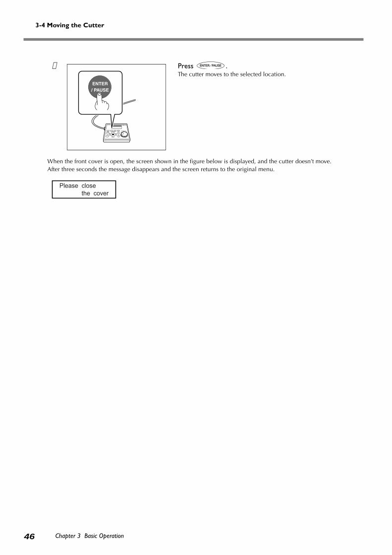
➍ Press .The cutter moves to the selected location.
When the front cover is open, the screen shown in the figure below is displayed, and the cutter doesn’t move.After three seconds the message disappears and the screen returns to the original menu.

47Chapter 3 Basic Operation
3-5 Spindle Operation
Starting and Stopping Spindle Rotation
This manually starts and stops rotation of the spindle. You perform the operation using the handy panel.☞ P. 35, "Spindle Run-in (Warm-up)"
Procedure
➊ Close the front cover.
➋ At the main screen, press and hold for one secondor longer.A beep is heard, and the spindle starts to turn.
➌ Press .The spindle stops turning, a beep is heard.
This operation cannot be performed in the following situations.
➢ When the machine is performing some operation➢ When the front cover is open (in which case the screen shown in the figure below is displayed)
☞ P. 103, “Responding to a Message”
Spindle rotation speed

3-5 Spindle Operation
48 Chapter 3 Basic Operation
FastSlow
Spindle speed
Adjusting the Spindle Speed
To adjust the speed of spindle rotation, turn on the handy panel.
The setting for the spindle speed can be made only onthe machine. Any setting made on the computer is ig-nored.
49Chapter 3 Basic Operation
3-6 Pausing and Stopping Cutting
Pausing and Resuming Cutting
This pauses cutting through operation using the handy panel. This enables you to move the cutter to the VIEW positionand check the status of the workpiece, then resume cutting at the location where you paused operation.
Procedure
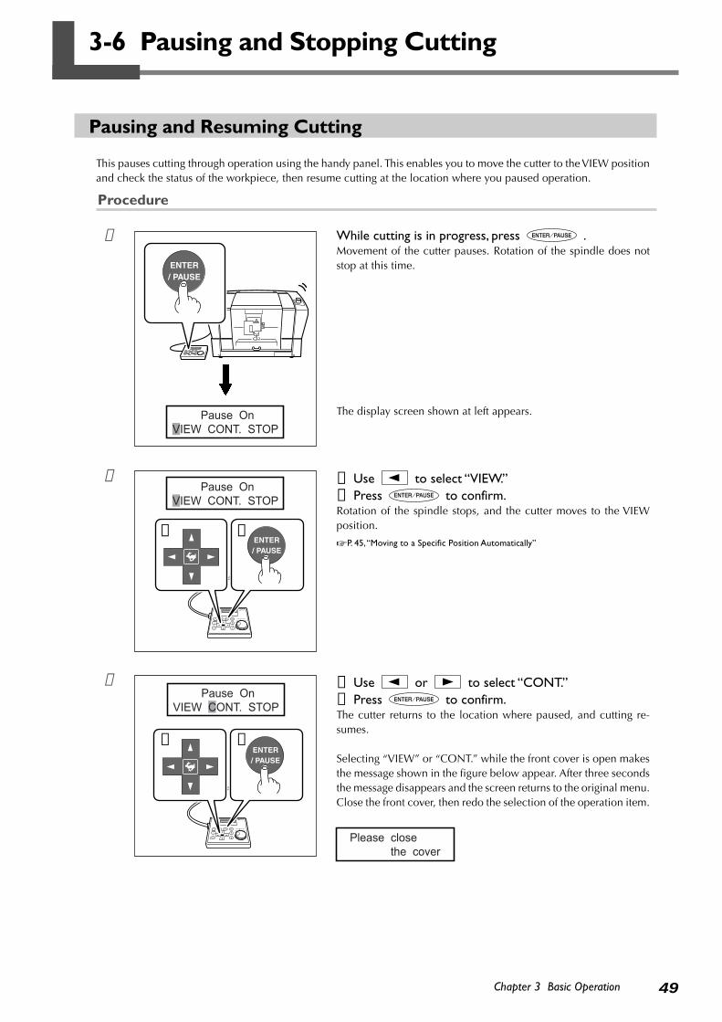
➊ While cutting is in progress, press .Movement of the cutter pauses. Rotation of the spindle does notstop at this time.
The display screen shown at left appears.
➋ ➀ Use to select “VIEW.”➁ Press to confirm.Rotation of the spindle stops, and the cutter moves to the VIEWposition.
☞ P. 45, “Moving to a Specific Position Automatically”
➌ ➀ Use or to select “CONT.”➁ Press to confirm.The cutter returns to the location where paused, and cutting re-sumes.
Selecting “VIEW” or “CONT.” while the front cover is open makesthe message shown in the figure below appear. After three secondsthe message disappears and the screen returns to the original menu.Close the front cover, then redo the selection of the operation item.
➀ ➁
➀ ➁
3-6 Pausing and Stopping Cutting
50 Chapter 3 Basic Operation
Important!
Before opening the front cover while operation is paused, first make sure that rotation of the spindle is stopped. Forsafety, opening the front cover while the spindle is turning makes the machine perform an emergency stop. Be sure tonote that if this happens, it’s necessary to quit the operation and start over from the beginning.
☞ P. 39, “Emergency Stop Due to Opening or Closing the Front Cover”
Other operations possible while paused➢ Starting or stopping spindle rotation☞ P. 47, “Starting and Stopping Spindle Rotation”
➢ Changing the spindle speed☞ P. 48, “Adjusting the Spindle Speed”
➢ Changing the feed rate of the cutter☞ P. 77, “Adjusting the Cutter Feed Rate During Engraving (Override)”
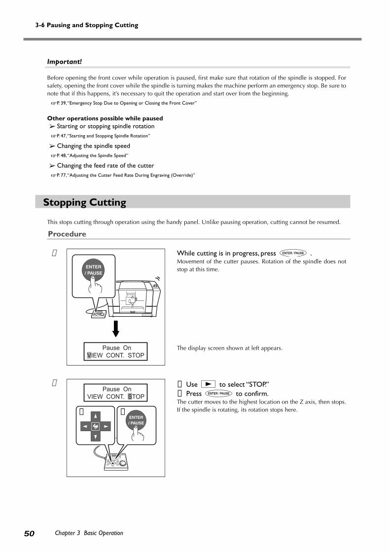
Stopping Cutting
This stops cutting through operation using the handy panel. Unlike pausing operation, cutting cannot be resumed.
Procedure
➊ While cutting is in progress, press .Movement of the cutter pauses. Rotation of the spindle does notstop at this time.
The display screen shown at left appears.
➋ ➀ Use to select “STOP.”➁ Press to confirm.The cutter moves to the highest location on the Z axis, then stops.If the spindle is rotating, its rotation stops here.➀ ➁

51
Chapter 4Engraving

52 Chapter 4 Engraving
4-1 Flow of Engraving Operations
1. StartupSwitch on the power switch to start the machine.
☞ P. 40, “How to Start the Machine”
2. Mounting the WorkpieceMount the workpiece to engrave on the table.
☞ P. 54, “Mounting a Workpiece”
To next page
ON

4-1 Flow of Engraving Operations
53Chapter 4 Engraving
5. Performing Engravings
When all the preparations are complete, send the engraving data from the computer and carry outengraving.
☞ P. 76, “Performing Engraving”
4. Setting the XY Origin Point
Set the engraving origin point for the X and Y axes.☞ P. 75, “Setting the XY Origin Point (Home Position)”
3. Cutter Installation and Basic Engraving Settings
Install the cutter to use for engraving. On this machine, you also set the Z-axis engraving originpoint at this time. The methods you use for installation and the settings differ depending onwhether you’re using the nose unit and on the cutter type. This manual describes the followingfour variations. Use these as a reference to select the optimal cutter for the purpose and use theappropriate methods for installing the cutter and making the settings.
➢ Character cutter or flat cutter (with the nose unit)☞ P. 56, “Cutter Installation Method 1 (With Nose Unit)”
➢ Character cutter or flat cutter (no nose unit)☞ P. 62, “Cutter Installation Method 2 (No Nose Unit)”
➢ Diamond scraper☞ P. 67, “Cutter Installation Method 3”
➢ End mill☞ P. 71, “Cutter Installation Method 4 (End mill)”
54 Chapter 4 Engraving
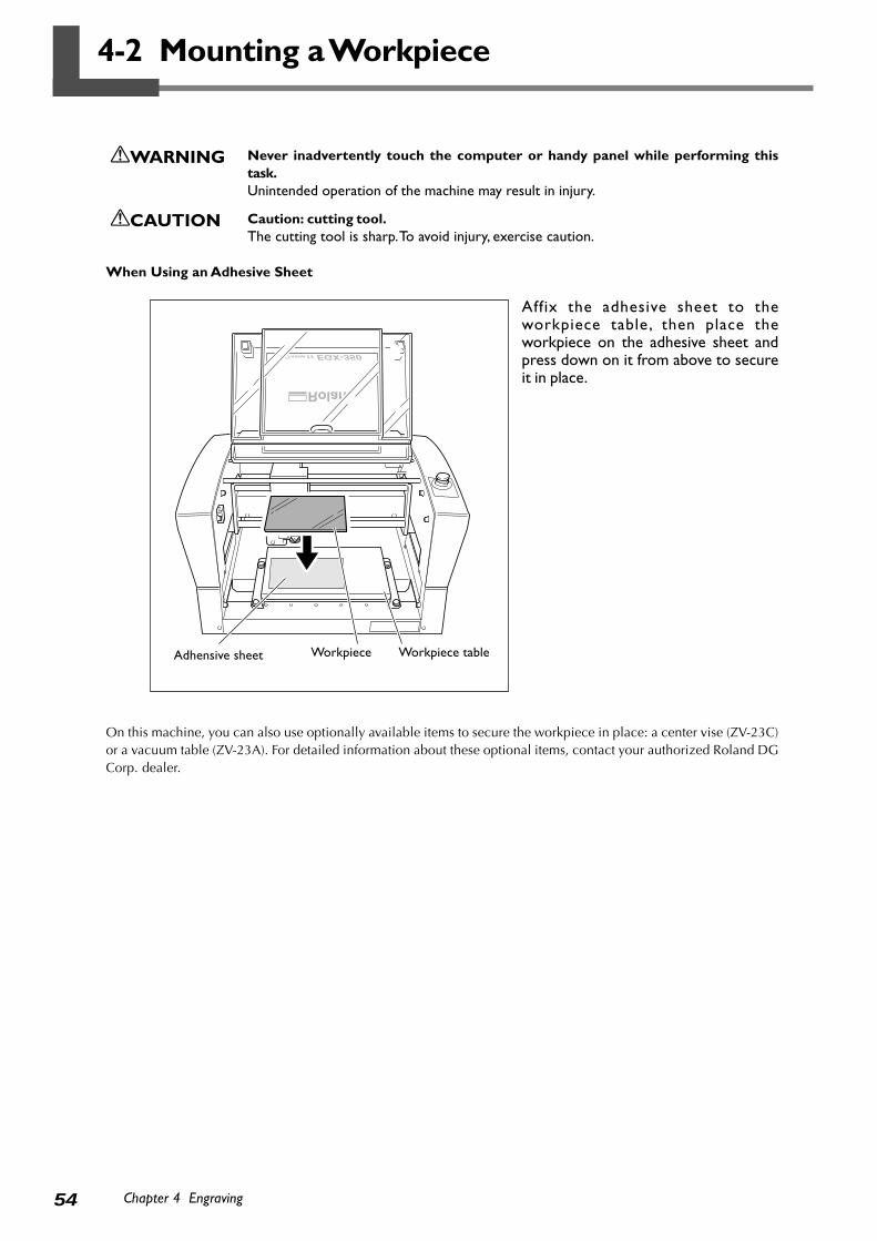
4-2 Mounting a Workpiece
WARNING Never inadvertently touch the computer or handy panel while performing thistask.Unintended operation of the machine may result in injury.
CAUTION Caution: cutting tool.The cutting tool is sharp. To avoid injury, exercise caution.
When Using an Adhesive Sheet
Affix the adhesive sheet to theworkpiece table, then place theworkpiece on the adhesive sheet andpress down on it from above to secureit in place.
On this machine, you can also use optionally available items to secure the workpiece in place: a center vise (ZV-23C)or a vacuum table (ZV-23A). For detailed information about these optional items, contact your authorized Roland DGCorp. dealer.
Workpiece Workpiece tableAdhensive sheet

55Chapter 4 Engraving
4-3 Selection of the Cutter (Usage Examples)
This machine can use cutters of a wide variety of types that have a diameter of 3.175 millimeters or 4.36 millimeters.Use an appropriate collet for the cutter’s diameter and type. For other cutters that can be used with the machine,contact your authorized Roland DG Corp. dealer.The table below shows samples of cutter usage, including use with or without a nose unit.
Important!
Use diameter-4.36 mm cutters at speeds of 15,000 rpm or lower. Use at higher speeds poses danger of damage to thespindle unit due to vibration.
CutterCharacter cutter
Flat cutter(*1)
Diamond scraper(*3)
End mill (*4)
With nose unit◆ Engraving acrylic and other plastic plates(*2)
☞ P. 56, "Cutter Installation Method 1"
◆ Unsuitable
◆ Unsuitable
No nose unit◆ Engraving plates of aluminum or brass◆ Three-dimensional engraving and creating re-liefs using plastic materials
☞ P. 62, "Cutter Installation Method 2"
◆ Scribing plates of aluminum or brass
☞ P. 67, "Cutter Installation Method 3"
◆ Creating reliefs and performing 3D cuttingusing plastic material☞ P. 71, "Cutter Installation Method 4"
*1: Diameter-4.36 millimeter cutters are optionally available items.*2: Use of the nose unit is not suitable for fill engraving at a width greater than the diameter of the nose-unit tip.☞ P. 61, “Important Notes When Using the Nose Unit”
*3: This is an optionally available item. Also, the diameter-4.36 millimeter diamond scraper cannot be used with theincluded solid collet. Provide a dedicated collet for diamond scrapers separately.
*4: This is an optionally available item. Provide a dedicated end-mill collet separately.

56 Chapter 4 Engraving
4-4 Cutter Installation Method 1 (With Nose Unit)
Installing a Character Cutter (With Nose Unit)
WARNING Never inadvertently touch the computer or handy panel while performing thistask.Unintended operation of the machine may result in injury.
WARNING Securely fasten the cutting tool and in place. After securing in place, make sure nowrenches or other articles have inadvertently been left behind.Otherwise such articles may be thrown from the machine with force, posing a risk ofinjury.
CAUTION Caution: cutting tool.The cutting tool is sharp. To avoid injury, exercise caution.
This performs engraving using the nose unit. When the tip of the nose unit touches the surface of the workpiece, thelocation is automatically detected as the Z origin point. This makes it possible to perform engraving at a uniform depthon a workpiece of uneven surface height. This also eliminates the need to set the Z-axis origin point each time whenyou’re engraving a number of different workpieces.
1. Install the cutter holder, solid collet, and nose unit.
➊ Install the cutter holder.While holding the spindle unit immobile witha wrench, tighten the cutter holder.The cutter holder is reverse-threaded (that is,you turn it counterclockwise to tighten it). Becareful to turn it in the correct direction.
Cutter holderWrench
Spindle unit
Type of cutter usedNose-unit usageSuitable workpiece types
Automatic Z-axis controlSpindle rotationLock-lever position
Character cutter or flat cutter
Used
Acrylic and other plastic-resin panelsNote: Aluminum, brass, and other easily scratched workpieces are notsuitable.
On
On
or
Cutter holder
Hexagonalscrewdriver
Loose

4-4 Cutter Installation Method 1 (With Nose Unit)
57Chapter 4 Engraving
➋ Install the solid collet.➀ Loosely tighten the solid collet.
Insert the solid collet into the spindle unitfrom below, then, while holding thespindle unit immobile with a wrench,tighten loosely.Use an appropriate solid collet for thecutter’s diameter.
➁ Fully tighten the solid collet.Using two wrenches, tighten the solidcollet fully. The appropriate tighteningtorque is 3.2 N-m (32kgf-cm) .
➌ Install the nose unit.Tighten until no further movement is possible,then loosen two turns.☞ P. 61, “Important Notes When Using the Nose Unit”
Wrench
Nose unit
Tighten
Loose
Spindle unit
Solid collet
Wrench
➀
➁
Wrench

4-4 Cutter Installation Method 1 (With Nose Unit)
58 Chapter 4 Engraving
2. Set the lock lever.
Set the lock lever at the or posi-tion.For detailed information about the settingposition for the lock lever, refer to the pageindicated below.☞ P. 82, “The Position of the Lock Lever”
3. Make the settings for spindle speed and Z-axis control.
➊ Press several times to display the screen shown at left.Use and to select [OTHERS].Press .
➋ Press to select “ON.”Press to confirm.
➌ Press .Use to select “ON.”The machine automatically determines the Z-axis origin during cutting accord-ing to the height of the workpiece.Press to confirm.
The message shown at left is displayed for three seconds, and then the originalscreen returns.
➍ Press .Use and to select the value.This makes the setting for the distance the cutter rises from the Z-axis originpoint during cutting (the cut-out amount). When making this setting, take intoaccount the shape of the workpiece and the time required for movement.Press to confirm.
➎ Press several times to return to the main screen.The Z-axis coordinate display changes to “AUTO.”
Lock leverPress down to lowerslightly.
4-4 Cutter Installation Method 1 (With Nose Unit)
59Chapter 4 Engraving
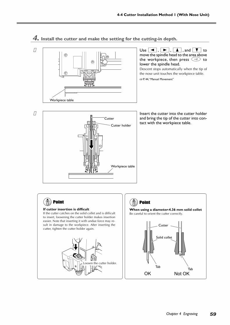
4. Install the cutter and make the setting for the cutting-in depth.
➊ Use , , , and tomove the spindle head to the area abovethe workpiece, then press tolower the spindle head.Descent stops automatically when the tip ofthe nose unit touches the workpiece table.
☞ P. 44, “Manual Movement”
➋ Insert the cutter into the cutter holderand bring the tip of the cutter into con-tact with the workpiece table.
If cutter insertion is difficultIf the cutter catches on the solid collet and is difficultto insert, loosening the cutter holder makes insertioneasier. Note that inserting it with undue force may re-sult in damage to the workpiece. After inserting thecutter, tighten the cutter holder again.
When using a diameter-4.36 mm solid colletBe careful to orient the cutter correctly.
Cutter
Solid collet
Workpiece table
Cutter
Cutter holder
Workpiece table
Loosen the cutter holder.
TabTab

4-4 Cutter Installation Method 1 (With Nose Unit)
60 Chapter 4 Engraving
➌ Secure the cutter in place.Tighten the mounting screw for the cutterholder.
➍ Make the setting for the cutting-in depth.➀ Tighten the nose unit to match the
desired cutting-in depth.The amount of extension of the cutter isthe cutting-in depth.1 scale tick = 0.0254 mm (0.001 in.)1 full turn = 0.635 mm (0.025 in.)An amount of 4 to 8 scale ticks corre-sponds to 0.1 to 0.2 mm (0.004 to 0.008in.).
➁ Secure the nose unit in place withthe retaining screw.
This completes the installation of the cutter. Go on to page 75, “Setting the XY Origin Point (Home Position)."
➀ Nose unit
➁ Retaining screw
Storage methods for diameter-3.175 mm cuttersWhen you want to perform repeated use while keeping the amount of extension of the cutter tip constant, then onceyou’ve decided on the amount of extension, we recommend removing the cutter holder and cutter from the spindle unitwithout separating them from one another. Storing the assembly without changing the position of the cutter holder elimi-nates the need to determine the amount of cutter extension each time with every use.Note, however, that this method cannot be used with the included diameter-4.36 millimeter solid collet.
Remove the entire cutter-holder assembly from the spindle unit. Store without changing the positionof the cutter holder.
Cutter holder
Hexagonalscrewdriver
Mounting screw
Retainingscrew
Spring

4-4 Cutter Installation Method 1 (With Nose Unit)
61Chapter 4 Engraving
Important Notes When Using the Nose Unit
Amount of Height Displacement That Can Be Tracked
When automatic Z control is set to “ON,” then as long as the tip of the nose unit is in contact with the surface of theworkpiece, the cutting-in depth can be kept uniform even if the height of the material changes. However, there is anupper limit to the amount of height displacement that can be tracked. Before you do the actual engraving, carry out anengraving test to make sure the desired engraving can be accomplished.(Trackable undulation height: gentle undulations of about 1 millimeter)
Limitations on Cutting
Care is needed when performing fill engraving (flat-drag cutting inside the contour lines of characters and shapes) overa wide surface area. With fill engraving that is broader than the diameter of the nose unit, the nose unit may track thesurface that has already been cut and cut the surface further.
8 mm
Nose unit
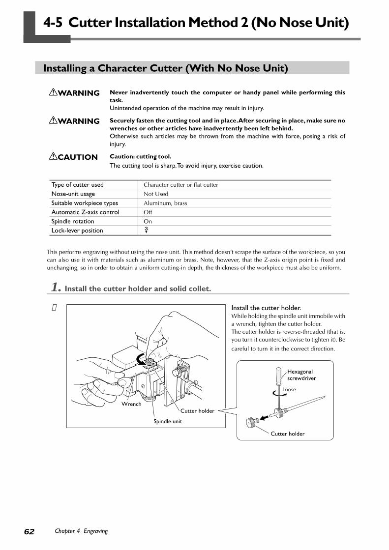
62 Chapter 4 Engraving
4-5 Cutter Installation Method 2 (No Nose Unit)
Installing a Character Cutter (With No Nose Unit)
WARNING Never inadvertently touch the computer or handy panel while performing thistask.Unintended operation of the machine may result in injury.
WARNING Securely fasten the cutting tool and in place. After securing in place, make sure nowrenches or other articles have inadvertently been left behind.Otherwise such articles may be thrown from the machine with force, posing a risk ofinjury.
CAUTION Caution: cutting tool.
The cutting tool is sharp. To avoid injury, exercise caution.
This performs engraving without using the nose unit. This method doesn’t scrape the surface of the workpiece, so youcan also use it with materials such as aluminum or brass. Note, however, that the Z-axis origin point is fixed andunchanging, so in order to obtain a uniform cutting-in depth, the thickness of the workpiece must also be uniform.
1. Install the cutter holder and solid collet.
➊ Install the cutter holder.While holding the spindle unit immobile witha wrench, tighten the cutter holder.The cutter holder is reverse-threaded (that is,you turn it counterclockwise to tighten it). Be
careful to turn it in the correct direction.
Type of cutter usedNose-unit usageSuitable workpiece typesAutomatic Z-axis controlSpindle rotationLock-lever position
Character cutter or flat cutter
Not Used
Aluminum, brass
Off
On
Cutter holderWrench
Spindle unit
Cutter holder
Hexagonalscrewdriver
Loose

4-5 Cutter Installation Method 2 (No Nose Unit)
63Chapter 4 Engraving
➋ Install the solid collet.➀ Loosely tighten the solid collet.
Insert the solid collet into the spindle unitfrom below, then, while holding thespindle unit immobile with a wrench,tighten loosely.Use an appropriate solid collet for thecutter’s diameter.
➁ Fully tighten the solid collet.Using two wrenches, tighten the solidcollet fully. The appropriate tighteningtorque is 3.2 N-m (32kgf-cm) .
2. Set the lock lever.
Set the lock lever at the position.The spindle head is secured in place.
☞ P. 82, "The Position of the Lock Lever"
Lock leverLift up.
Wrench
Spindle unit
Solid collet
Wrench
➀
➁
Wrench
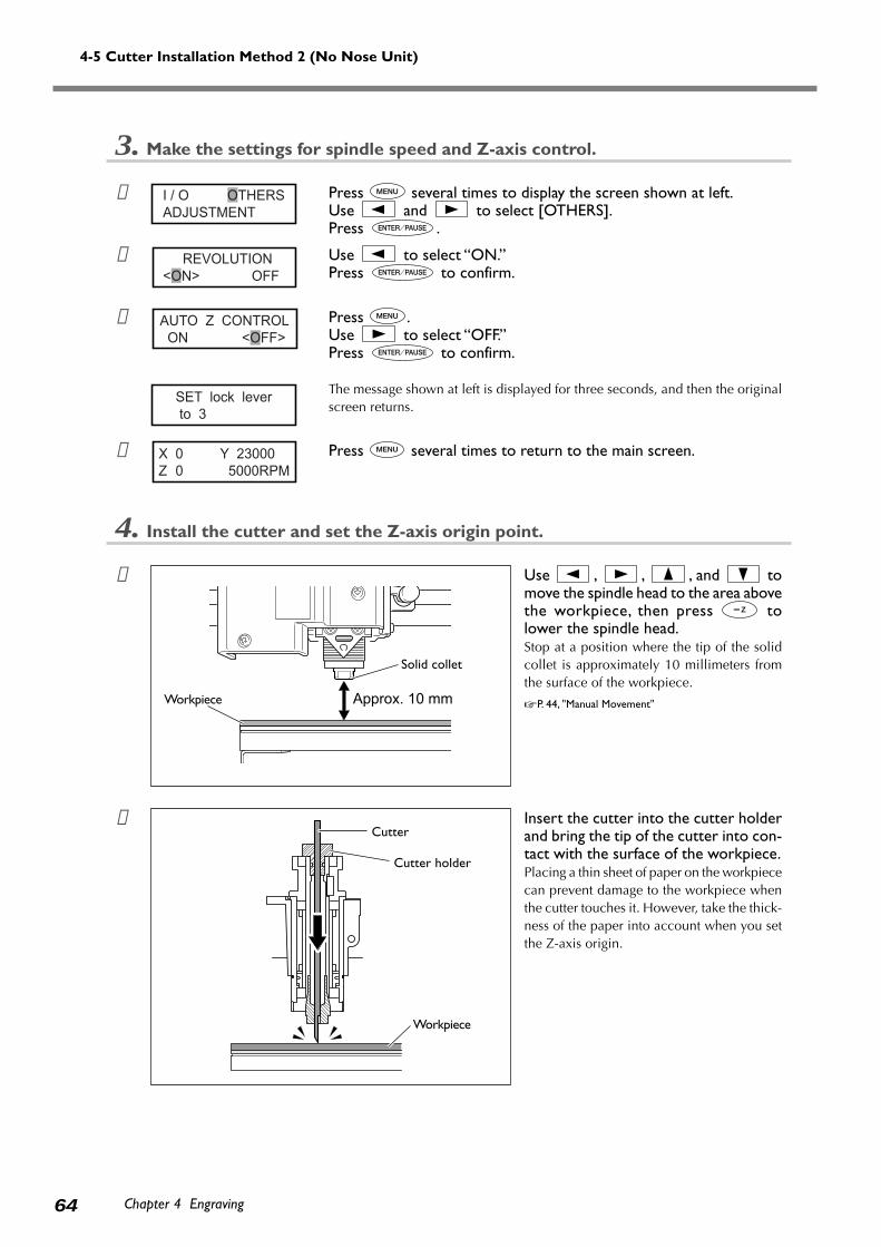
4-5 Cutter Installation Method 2 (No Nose Unit)
64 Chapter 4 Engraving
3. Make the settings for spindle speed and Z-axis control.
➊ Press several times to display the screen shown at left.Use and to select [OTHERS].Press .
➋ Use to select “ON.”Press to confirm.
➌ Press .Use to select “OFF.”Press to confirm.
The message shown at left is displayed for three seconds, and then the originalscreen returns.
➍ Press several times to return to the main screen.
4. Install the cutter and set the Z-axis origin point.
➊ Use , , , and tomove the spindle head to the area abovethe workpiece, then press tolower the spindle head.Stop at a position where the tip of the solidcollet is approximately 10 millimeters fromthe surface of the workpiece.
☞ P. 44, "Manual Movement"
➋ Insert the cutter into the cutter holderand bring the tip of the cutter into con-tact with the surface of the workpiece.Placing a thin sheet of paper on the workpiececan prevent damage to the workpiece whenthe cutter touches it. However, take the thick-ness of the paper into account when you setthe Z-axis origin.
Solid collet
Workpiece
Cutter
Cutter holder
Workpiece

4-5 Cutter Installation Method 2 (No Nose Unit)
65Chapter 4 Engraving
➌ Secure the cutter in place.Tighten the mounting screw for the cutterholder.
➍ Press .
➎ Use and to select [Z0].
➏ Press to confirm.The Z-axis origin is set.
➐ Press .The main display appears. The coordinate values for Z is set to 0.
This completes the installation of the cutter. Go on to page 75, “Setting the XY Origin Point (Home Position)."
If cutter insertion is difficultIf the cutter catches on the solid collet and is difficult toinsert, loosening the cutter holder makes insertion easier.Note that inserting it with undue force may result indamage to the workpiece. After inserting the cutter,tighten the cutter holder again.
When using a diameter-4.36 mm solid colletBe careful to orient the cutter correctly.
Loosen the cutter holder.
Cutter
Solid collet
TabTab
Cutter holder
Hexagonalscrewdriver
Mounting screw

4-5 Cutter Installation Method 2 (No Nose Unit)
66 Chapter 4 Engraving
Storage methods for diameter-3.175 mm cuttersWhen you want to perform repeated use while keeping the amount of extension of the cutter tip constant, then onceyou’ve decided on the amount of extension, we recommend removing the cutter holder and cutter from the spindle unitwithout separating them from one another. Storing the assembly without changing the position of the cutter holder elimi-nates the need to determine the amount of cutter extension each time with every use.Note, however, that this method cannot be used with the included diameter-4.36 millimeter solid collet.
Remove the entire cutter-holder assembly from the spindle unit. Store without changing the positionof the cutter holder.
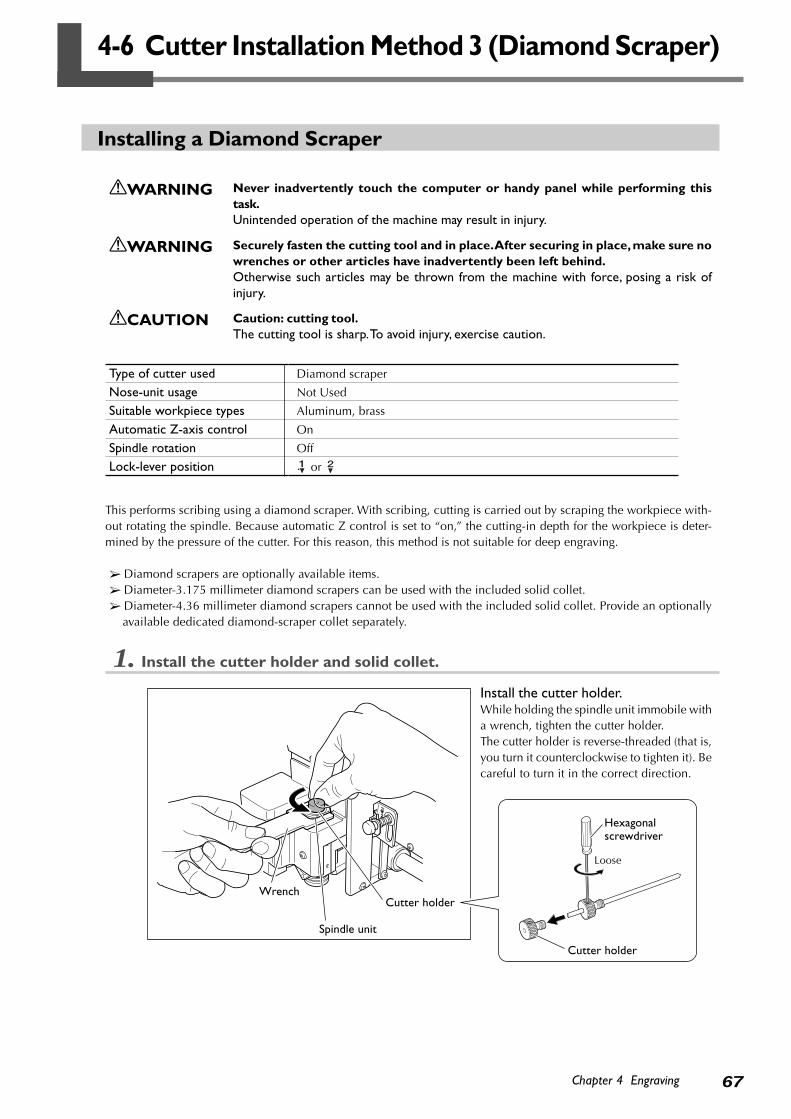
67Chapter 4 Engraving
4-6 Cutter Installation Method 3 (Diamond Scraper)
Installing a Diamond Scraper
WARNING Never inadvertently touch the computer or handy panel while performing thistask.Unintended operation of the machine may result in injury.
WARNING Securely fasten the cutting tool and in place. After securing in place, make sure nowrenches or other articles have inadvertently been left behind.Otherwise such articles may be thrown from the machine with force, posing a risk ofinjury.
CAUTION Caution: cutting tool.The cutting tool is sharp. To avoid injury, exercise caution.
This performs scribing using a diamond scraper. With scribing, cutting is carried out by scraping the workpiece with-out rotating the spindle. Because automatic Z control is set to “on,” the cutting-in depth for the workpiece is deter-mined by the pressure of the cutter. For this reason, this method is not suitable for deep engraving.
➢ Diamond scrapers are optionally available items.➢ Diameter-3.175 millimeter diamond scrapers can be used with the included solid collet.➢ Diameter-4.36 millimeter diamond scrapers cannot be used with the included solid collet. Provide an optionally
available dedicated diamond-scraper collet separately.
1. Install the cutter holder and solid collet.
Install the cutter holder.While holding the spindle unit immobile witha wrench, tighten the cutter holder.The cutter holder is reverse-threaded (that is,you turn it counterclockwise to tighten it). Becareful to turn it in the correct direction.
Type of cutter usedNose-unit usageSuitable workpiece typesAutomatic Z-axis controlSpindle rotationLock-lever position
Diamond scraper
Not Used
Aluminum, brass
On
Off
or
Cutter holderWrench
Spindle unit
Cutter holder
Hexagonalscrewdriver
Loose

4-6 Cutter Installation Method 3 (Diamond Scraper)
68 Chapter 4 Engraving
➋ Install the solid collet.➀ Loosely tighten the solid collet.
Insert the solid collet into the spindle unitfrom below, then, while holding thespindle unit immobile with a wrench,tighten loosely.Diameter-4.36 millimeter diamond scrap-ers cannot be used with the included solidcollet. Provide a dedicated diamond-scraper collet separately.
➁ Fully tighten the solid collet.Using two wrenches, tighten the solidcollet fully. The appropriate tighteningtorque is 3.2 N-m (32kgf-cm) .
2. Set the lock lever.
Set the lock lever at the or posi-tion.For detailed information about the settingposition for the lock lever, refer to the pageindicated below.
☞ P. 82, “The Position of the Lock Lever”
Lock leverPress down to lowerslightly.
Wrench
Spindle unit
Solid collet
Wrench
➀
➁
Wrench
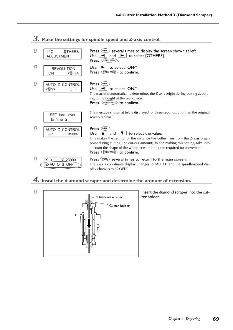
4-6 Cutter Installation Method 3 (Diamond Scraper)
69Chapter 4 Engraving
3. Make the settings for spindle speed and Z-axis control.
➊ Press several times to display the screen shown at left.Use and to select [OTHERS].Press .
➋ Use to select “OFF.”Press to confirm.
➌ Press .Use to select “ON.”The machine automatically determines the Z-axis origin during cutting accord-ing to the height of the workpiece.Press to confirm.
The message shown at left is displayed for three seconds, and then the originalscreen returns.
➍ Press .Use and to select the value.This makes the setting for the distance the cutter rises from the Z-axis originpoint during cutting (the cut-out amount). When making this setting, take intoaccount the shape of the workpiece and the time required for movement.Press to confirm.
➎ Press several times to return to the main screen.The Z-axis coordinate display changes to “AUTO” and the spindle-speed dis-play changes to “S OFF.”
4. Install the diamond scraper and determine the amount of extension.
➊ Insert the diamond scraper into the cut-ter holder.Diamond scraper
Cutter holder
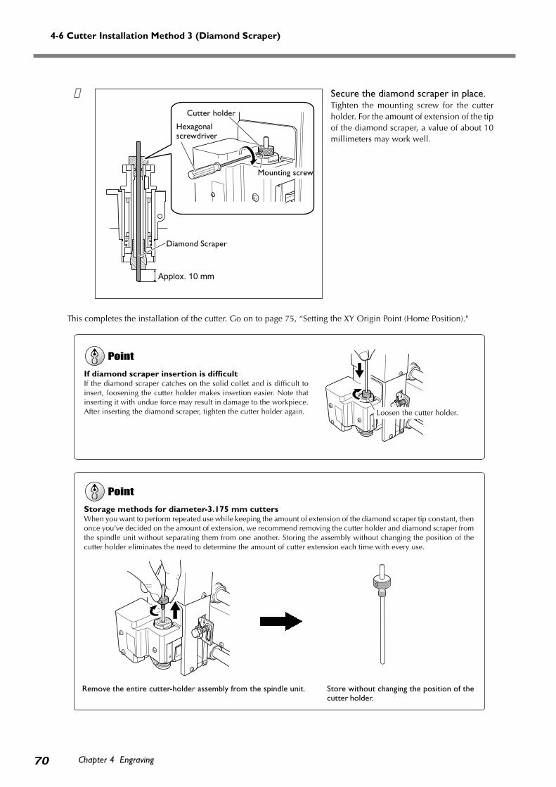
4-6 Cutter Installation Method 3 (Diamond Scraper)
70 Chapter 4 Engraving
➋ Secure the diamond scraper in place.Tighten the mounting screw for the cutterholder. For the amount of extension of the tipof the diamond scraper, a value of about 10millimeters may work well.
This completes the installation of the cutter. Go on to page 75, “Setting the XY Origin Point (Home Position)."
Hexagonalscrewdriver
Cutter holder
Mounting screw
Storage methods for diameter-3.175 mm cuttersWhen you want to perform repeated use while keeping the amount of extension of the diamond scraper tip constant, thenonce you’ve decided on the amount of extension, we recommend removing the cutter holder and diamond scraper fromthe spindle unit without separating them from one another. Storing the assembly without changing the position of thecutter holder eliminates the need to determine the amount of cutter extension each time with every use.
Remove the entire cutter-holder assembly from the spindle unit. Store without changing the position of thecutter holder.
Diamond Scraper
If diamond scraper insertion is difficultIf the diamond scraper catches on the solid collet and is difficult toinsert, loosening the cutter holder makes insertion easier. Note thatinserting it with undue force may result in damage to the workpiece.After inserting the diamond scraper, tighten the cutter holder again. Loosen the cutter holder.
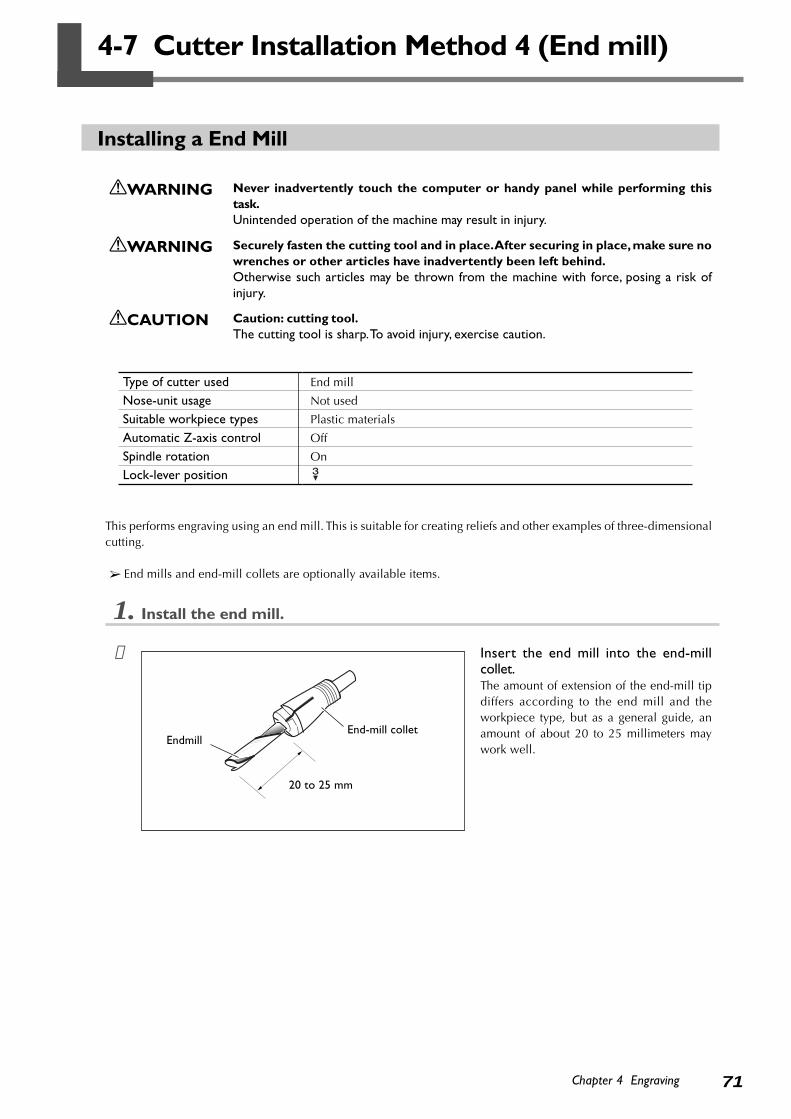
71Chapter 4 Engraving
4-7 Cutter Installation Method 4 (End mill)
Installing a End Mill
WARNING Never inadvertently touch the computer or handy panel while performing thistask.Unintended operation of the machine may result in injury.
WARNING Securely fasten the cutting tool and in place. After securing in place, make sure nowrenches or other articles have inadvertently been left behind.Otherwise such articles may be thrown from the machine with force, posing a risk ofinjury.
CAUTION Caution: cutting tool.The cutting tool is sharp. To avoid injury, exercise caution.
This performs engraving using an end mill. This is suitable for creating reliefs and other examples of three-dimensionalcutting.
➢ End mills and end-mill collets are optionally available items.
1. Install the end mill.
➊ Insert the end mill into the end-millcollet.The amount of extension of the end-mill tipdiffers according to the end mill and theworkpiece type, but as a general guide, anamount of about 20 to 25 millimeters maywork well.
EndmillEnd-mill collet
20 to 25 mm
Type of cutter usedNose-unit usageSuitable workpiece typesAutomatic Z-axis controlSpindle rotationLock-lever position
End mill
Not used
Plastic materials
Off
On
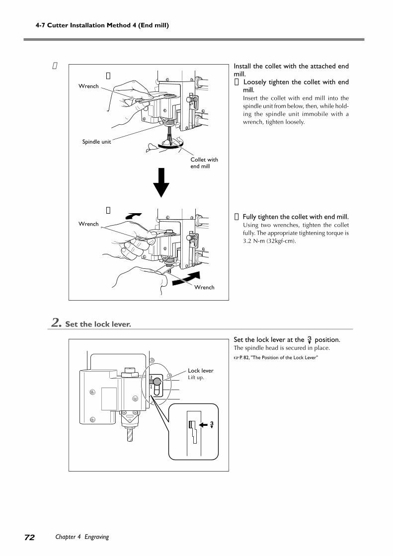
4-7 Cutter Installation Method 4 (End mill)
72 Chapter 4 Engraving
➋ Install the collet with the attached endmill.➀ Loosely tighten the collet with end
mill.Insert the collet with end mill into thespindle unit from below, then, while hold-ing the spindle unit immobile with awrench, tighten loosely.
➁ Fully tighten the collet with end mill.Using two wrenches, tighten the colletfully. The appropriate tightening torque is3.2 N-m (32kgf-cm).
2. Set the lock lever.
Set the lock lever at the position.The spindle head is secured in place.
☞ P. 82, "The Position of the Lock Lever"
Wrench
Wrench
Spindle unit
Collet withend mill
Lock leverLift up.
➀
➁
Wrench
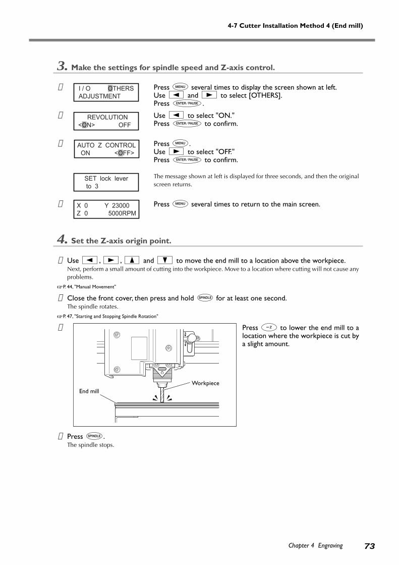
4-7 Cutter Installation Method 4 (End mill)
73Chapter 4 Engraving
3. Make the settings for spindle speed and Z-axis control.
➊ Press several times to display the screen shown at left.Use and to select [OTHERS].Press .
➋ Use to select "ON."Press to confirm.
➌ Press .Use to select "OFF."Press to confirm.
The message shown at left is displayed for three seconds, and then the originalscreen returns.
➍ Press several times to return to the main screen.
4. Set the Z-axis origin point.
➊ Use , , and to move the end mill to a location above the workpiece.Next, perform a small amount of cutting into the workpiece. Move to a location where cutting will not cause anyproblems.
☞ P. 44, "Manual Movement"
➋ Close the front cover, then press and hold for at least one second.The spindle rotates.
☞ P. 47, "Starting and Stopping Spindle Rotation"
➌ Press to lower the end mill to alocation where the workpiece is cut bya slight amount.
➍ Press .The spindle stops.
WorkpieceEnd mill

4-7 Cutter Installation Method 4 (End mill)
74 Chapter 4 Engraving
➎ Press .
➏ Use and to select [Z0].
➐ Press to confirm.The Z-axis origin point is set.
➑ Press .The main display appears. The coordinate values for Z is set to 0.
This completes the installation of the end mill. Go on to page 75, “Setting the XY Origin Point (Home Position)."

75Chapter 4 Engraving
4-8 Setting the XY Origin Point
Setting the XY Origin Point (Home Position)
This sets the X- and Y-axis coordinates used as the origin point for cutting. This location is termed the XY origin point,which on this machine is called the “home position.” On this machine, you can set the XY origin anywhere within theoperating range. Set it to match the engraving data and the position of the mounted workpiece.
☞ P. 45, “Moving to a Specific Position Automatically,”
Procedure
➊ Install a cutter and mount a workpiece.☞ P. 54, “Mounting a Workpiece,” and p. 56 through 71, “Cutter Installation Method 1” through “Cutter Installation Method 4”
➋ Move the cutter to the location youwant to make the XY origin point (thehome position).☞ P. 44, “Manual Movement”
➌ Press .
➍ Press to confirm.The XY origin point (the home position) is set.
➎ Press .The main display appears. The coordinate values for X and Y are set to 0.
Origin

76 Chapter 4 Engraving
4-9 Performing Engraving
Performing Engraving
Make sure the following tasks have all been completed, then sent the engraving data from the computer and performengraving.
➢ Mounting a Workpiece☞ P. 54, “Mounting a Workpiece”
➢ Cutter Installation☞ P. 56 through 71, “Cutter Installation Method 1” through “Cutter Installation Method 4”
➢ Setting the XY Origin Point☞ P. 75, “Setting the XY Origin Point (Home Position)”
For information about creating engraving data, refer to the documentation for the program you’re using to create thedata.

4-9 Performing Engraving
77Chapter 4 Engraving
Adjusting the Cutter Feed Rate During Engraving (Override)
While engraving is in progress, you can pause operation and adjust the feed rate for the cutter. You adjust the feed rateby specifying a ratio of change relative to the present feed rate. This feature is called “override.”The feed rate can be adjusted only within the machine’s settable feed-rate range. If a feed rate that falls outside thesettable range is set by an override, the actual feed rate is limited to the maximum or minimum feed rate.
Procedure
➊ While engraving is in progress, press .Engraving pauses.
☞ P. 54, “Mounting a Workpiece”
➋ Press .Use and to set the ratio for feed-rate adjustment.Press to confirm.
➌ Press .The screen shown at left returns.
➍ Use or to select “CONT.” and press .Engraving resumes.
➢ Settable change ratios10 to 200% (in steps of 10%)
➢ Settable range for feed rateX- and Y-axis directions: 0.1 to 60 mm/sec (0.004 to 2.4 in./sec)Z-axis direction: 0.1 to 30 mm/sec (0.004 to 1.2 in./sec)
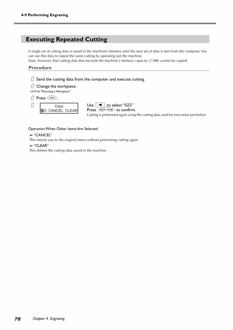
4-9 Performing Engraving
78 Chapter 4 Engraving
Executing Repeated Cutting
A single set of cutting data is saved in the machine’s memory until the next set of data is sent from the computer. Youcan use this data to repeat the same cutting by operating just the machine.Note, however, that cutting data that exceeds the machine’s memory capacity (2 MB) cannot be copied.
Procedure
➊ Send the cutting data from the computer and execute cutting.
➋ Change the workpiece.☞ P. 54, “Mounting a Workpiece”
➌ Press .
➍ Use to select “GO.”Press to confirm.Cutting is performed again using the cutting data used for execution just before.
Operation When Other Items Are Selected
➢ “CANCEL”This returns you to the original menu without performing cutting again.
➢ “CLEAR”This deletes the cutting data saved in the machine.

79
Chapter 5Feature reference

80 Chapter 5 Feature reference
5-1 Attaching the Vacuum Adapter for Chip Cleaning
WARNING Exercise caution to prevent fire or dust explosion.Taking up fine cuttings using an ordinary vacuum cleaner may cause danger of fire orexplosion. Check with the manufacturer of the vacuum cleaner. When the safety of usecannot be determined, never use the vacuum adapter and a vacuum cleaner.
WARNING Make the connection while exercising care not to touch the tip of the cutter.Contact with the blade may cause injury.
WARNING Never touch the spindle unit immediately after cutting.Doing so may cause burns.
Before Using the Vacuum Adapter, Be Sure to Verify the Following Points
➣ Use a vacuum cleaner that allows adjustment of the suction force and is equipped with an overload protector.To prevent fire or explosion, carefully check the specifications of your vacuum cleaner before use, includingcontacting the manufacturer if necessary.
➣ Be sure to use the nose unit.The vacuum adapter cannot be attached unless the nose unit is installed.
☞ P. 56, “Cutter Installation Method 1 ”
➣ Install so as to leave at least 30 centimeters (11.9 in.) of free space at the back of the machine.Malfunction may occur if the hose cannot move freely.
➣ Be sure to use a vacuum-cleaner hose having a diameter that allows connection with the vacuum adapter.The diameter of the vacuum adapter is 32 millimeter (1.3 in.).

5-1 Attaching the Vacuum Adapter for Chip Cleaning
81Chapter 5 Feature reference
Move the spindle head to the front left of the workpiece table, then attach the vacuum adapter for chip cleaning asshown in the figure. Using the vacuum adapter for chip cleaning enables the vacuum cleaner to take up cutting wasteduring cutting, which can help keep scattering of cutting waste to a minimum.
☞ P. 44, "Manual Movement"
Position so that the retaining screwfor the nose unit is between the tabsof the clamp.
Retainingscrew
TabTab
Bar
HosePass through above the bar.
Vacuum adapterclamp
Hose
Front
Top
Hose
Nose unit
32mm(1.3 in.)
Rear
ClampSecure in placeat the locationswhere the audibleclick is heard.
Provide a gap largeenough to ensure nostriking.
Opening the clamp
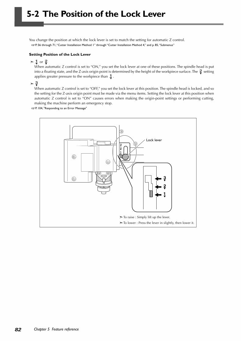
82 Chapter 5 Feature reference
5-2 The Position of the Lock Lever
You change the position at which the lock lever is set to match the setting for automatic Z control.☞ P. 56 through 71, “Cutter Installation Method 1” through “Cutter Installation Method 4,” and p. 85, “Submenus”
Setting Position of the Lock Lever
➣ or When automatic Z control is set to “ON,” you set the lock lever at one of these positions. The spindle head is putinto a floating state, and the Z-axis origin point is determined by the height of the workpiece surface. The settingapplies greater pressure to the workpiece than .
➣ When automatic Z control is set to “OFF,” you set the lock lever at this position. The spindle head is locked, and sothe setting for the Z-axis origin point must be made via the menu items. Setting the lock lever at this position whenautomatic Z control is set to “ON” causes errors when making the origin-point settings or performing cutting,making the machine perform an emergency stop.
☞ P. 104, "Responding to an Error Message"
Lock lever
➣ To raise : Simply lift up the lever.
➣ To lower : Press the lever in slightly, then lower it.
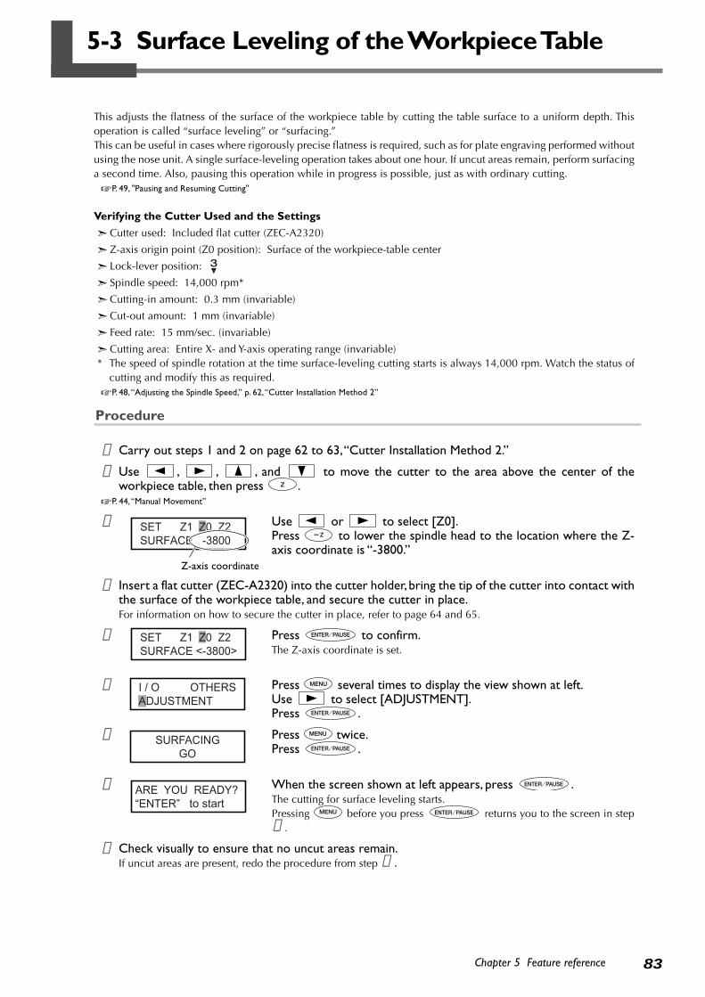
83Chapter 5 Feature reference
5-3 Surface Leveling of the Workpiece Table
This adjusts the flatness of the surface of the workpiece table by cutting the table surface to a uniform depth. Thisoperation is called “surface leveling” or “surfacing.”This can be useful in cases where rigorously precise flatness is required, such as for plate engraving performed withoutusing the nose unit. A single surface-leveling operation takes about one hour. If uncut areas remain, perform surfacinga second time. Also, pausing this operation while in progress is possible, just as with ordinary cutting.
☞ P. 49, "Pausing and Resuming Cutting"
Verifying the Cutter Used and the Settings
➣ Cutter used: Included flat cutter (ZEC-A2320)
➣ Z-axis origin point (Z0 position): Surface of the workpiece-table center
➣ Lock-lever position:
➣ Spindle speed: 14,000 rpm*
➣ Cutting-in amount: 0.3 mm (invariable)
➣ Cut-out amount: 1 mm (invariable)
➣ Feed rate: 15 mm/sec. (invariable)
➣ Cutting area: Entire X- and Y-axis operating range (invariable)* The speed of spindle rotation at the time surface-leveling cutting starts is always 14,000 rpm. Watch the status of
cutting and modify this as required.☞ P. 48, “Adjusting the Spindle Speed,” p. 62, “Cutter Installation Method 2”
Procedure
➊ Carry out steps 1 and 2 on page 62 to 63, “Cutter Installation Method 2.”
➋ Use , , , and to move the cutter to the area above the center of theworkpiece table, then press .
☞ P. 44, “Manual Movement”
➌ Use or to select [Z0].Press to lower the spindle head to the location where the Z-axis coordinate is “-3800.”
➍ Insert a flat cutter (ZEC-A2320) into the cutter holder, bring the tip of the cutter into contact withthe surface of the workpiece table, and secure the cutter in place.For information on how to secure the cutter in place, refer to page 64 and 65.
➎ Press to confirm.The Z-axis coordinate is set.
➏ Press several times to display the view shown at left.Use to select [ADJUSTMENT].Press .
➐ Press twice.Press .
➑ When the screen shown at left appears, press .The cutting for surface leveling starts.Pressing before you press returns you to the screen in step➐.
➒ Check visually to ensure that no uncut areas remain.If uncut areas are present, redo the procedure from step ➋.
Z-axis coordinate
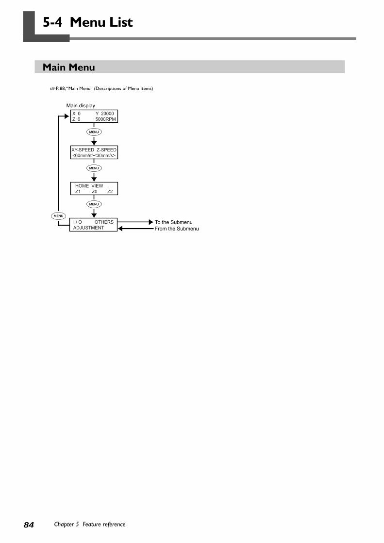
84 Chapter 5 Feature reference
5-4 Menu List
Main Menu
☞ P. 88, “Main Menu” (Descriptions of Menu Items)
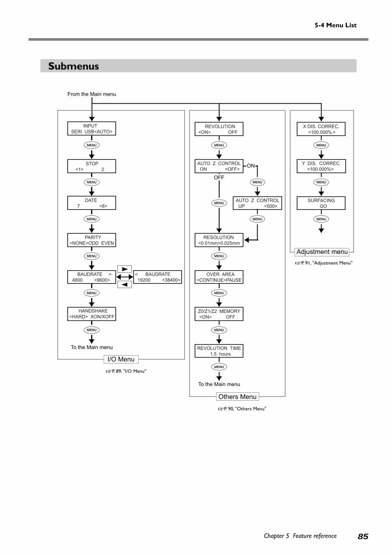
5-4 Menu List
85Chapter 5 Feature reference
Submenus
☞ P. 91, "Adjustment Menu"
☞ P. 89, "I/O Menu"
☞ P. 90, "Others Menu"
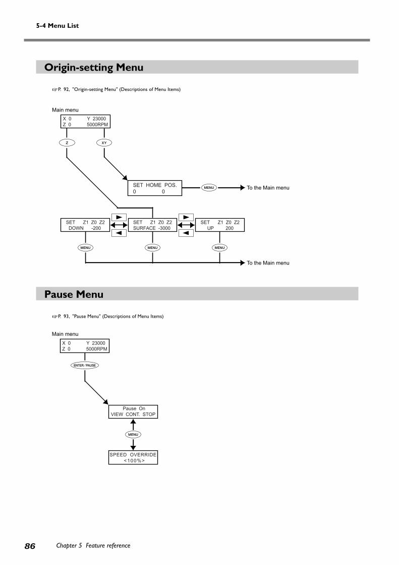
5-4 Menu List
86 Chapter 5 Feature reference
Origin-setting Menu
☞ P. 92, "Origin-setting Menu" (Descriptions of Menu Items)
Pause Menu
☞ P. 93, "Pause Menu" (Descriptions of Menu Items)
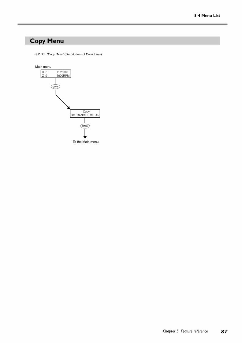
5-4 Menu List
87Chapter 5 Feature reference
Copy Menu
☞ P. 93, "Copy Menu" (Descriptions of Menu Items)
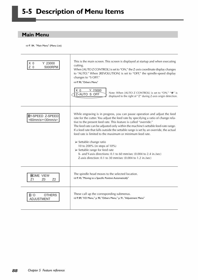
88 Chapter 5 Feature reference
5-5 Description of Menu Items
Main Menu
☞ P. 84, "Main Menu" (Menu List)
This is the main screen. This screen is displayed at startup and when executingcutting.When [AUTO Z CONTROL] is set to “ON,” the Z-axis coordinate display changesto “AUTO.” When [REVOLUTION] is set to “OFF,” the spindle-speed displaychanges to “S OFF.”
☞ P. 90, "Others Menu"
While engraving is in progress, you can pause operation and adjust the feedrate for the cutter. You adjust the feed rate by specifying a ratio of change rela-tive to the present feed rate. This feature is called “override.”The feed rate can be adjusted only within the machine’s settable feed-rate range.If a feed rate that falls outside the settable range is set by an override, the actualfeed rate is limited to the maximum or minimum feed rate.
➢ Settable change ratio10 to 200% (in steps of 10%)
➢ Settable range for feed rateX- and Y-axis directions: 0.1 to 60 mm/sec (0.004 to 2.4 in./sec)Z-axis direction: 0.1 to 30 mm/sec (0.004 to 1.2 in./sec)
The spindle head moves to the selected location.☞ P. 45, "Moving to a Specific Position Automatically"
These call up the corresponding submenus.☞ P. 89, "I/O Menu," p. 90, "Others Menu," p. 91, "Adjustment Menu"
Note: When [AUTO Z CONTROL] is set to “ON,” “ ” isdisplayed to the right of “Z” during Z-axis origin detection.

5-5 Description of Menu Items
89Chapter 5 Feature reference
I/O Menu (Submenu)
This selects the communication port for communication with the computer and makes the settings for the communi-cation parameters when using a serial connection. When you’re using a USB connection, simply selecting the com-munication port completes the settings you have to make. The setting menus for items other than the communicationport are displayed only when “SERI” or “AUTO” has been selected as the communication port. Select the settingvalues to match the communication parameters for the program you’re using.
☞P. 85, "Submenus"
This selects the connector for connection to a computer. Commands from thecomputer are received via the connector you specify here. When this is set to[AUTO], the connector through which commands are first received after powerupis enabled automatically. To change the port enabled when “AUTO” is selected,either redo the selection of “SERI” or “USB,” or switch off the machine’s powerand redo the operation from the beginning.When this is set to [SERI] or [AUTO], the menu for setting the serial communi-cation parameters appears.➢ Default setting: AUTO
This makes the setting for the number of stop bits, one of the serial communica-tion parameters. This is displayed only when [INPUT] is set to [SERI] or [AUTO].➢ Default setting: 1
This makes the setting for the data bit length, one of the serial communicationparameters. This is displayed only when [INPUT] is set to [SERI] or [AUTO].➢ Default setting: 8
This makes the setting for parity, one of the serial communication parameters.This is displayed only when [INPUT] is set to [SERI] or [AUTO].➢ Default setting: NONE
This makes the setting for the baud rate, one of the serial communication pa-rameters. This is displayed only when [INPUT] is set to [SERI] or [AUTO].➢ Default setting: 9600
This makes the setting for handshaking (flow control), one of the serial commu-nication parameters. [HARD] indicates hardware handshaking, and [XON/OFF]indicates XON/XOFF handshaking. This is displayed only when [INPUT] is setto [SERI] or [AUTO].➢ Default setting: HARD
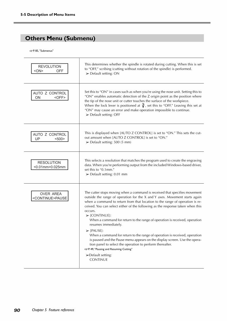
5-5 Description of Menu Items
90 Chapter 5 Feature reference
Others Menu (Submenu)
☞ P. 85, "Submenus"
This determines whether the spindle is rotated during cutting. When this is setto “OFF,” scribing (cutting without rotation of the spindle) is performed.➢ Default setting: ON
Set this to “ON” in cases such as when you’re using the nose unit. Setting this to“ON” enables automatic detection of the Z origin point as the position wherethe tip of the nose unit or cutter touches the surface of the workpiece.When the lock lever is positioned at , set this to “OFF.” Leaving this set at“ON” may cause an error and make operation impossible to continue.➢ Default setting: OFF
This is displayed when [AUTO Z CONTROL] is set to “ON.” This sets the cut-out amount when [AUTO Z CONTROL] is set to “ON.”➢ Default setting: 500 (5 mm)
This selects a resolution that matches the program used to create the engravingdata. When you’re performing output from the included Windows-based driver,set this to “0.1mm.”➢ Default setting: 0.01 mm
The cutter stops moving when a command is received that specifies movementoutside the range of operation for the X and Y axes. Movement starts againwhen a command to return from that location to the range of operation is re-ceived. You can select either of the following as the response taken when thisoccurs.➢ [CONTINUE]:
When a command for return to the range of operation is received, operationresumes immediately.
➢ [PAUSE]:When a command for return to the range of operation is received, operationis paused and the Pause menu appears on the display screen. Use the opera-tion panel to select the operation to perform thereafter.
☞ P. 49, “Pausing and Resuming Cutting”
➢Default setting:CONTINUE
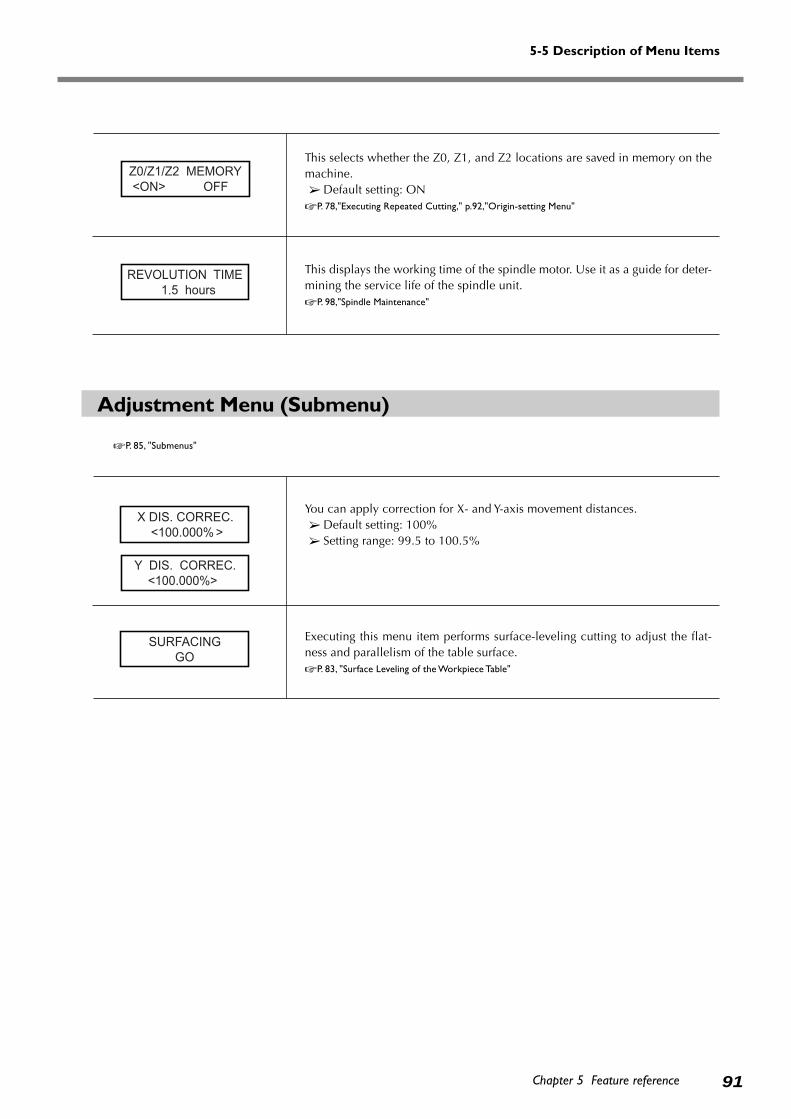
5-5 Description of Menu Items
91Chapter 5 Feature reference
This selects whether the Z0, Z1, and Z2 locations are saved in memory on themachine.➢ Default setting: ON
☞ P. 78,"Executing Repeated Cutting," p.92,"Origin-setting Menu"
This displays the working time of the spindle motor. Use it as a guide for deter-mining the service life of the spindle unit.☞ P. 98,"Spindle Maintenance"
Adjustment Menu (Submenu)
☞ P. 85, "Submenus"
You can apply correction for X- and Y-axis movement distances.➢ Default setting: 100%➢ Setting range: 99.5 to 100.5%
Executing this menu item performs surface-leveling cutting to adjust the flat-ness and parallelism of the table surface.☞ P. 83, "Surface Leveling of the Workpiece Table"
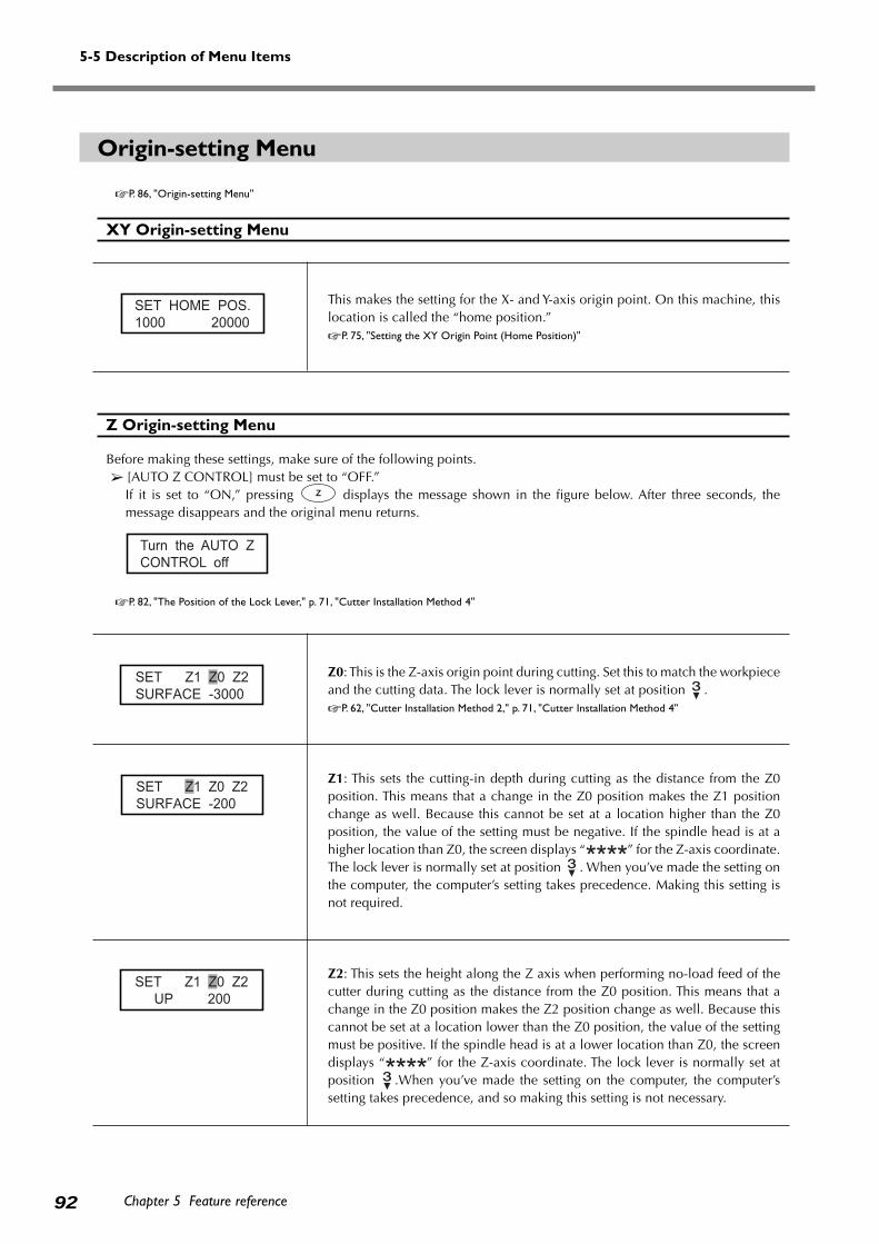
5-5 Description of Menu Items
92 Chapter 5 Feature reference
Origin-setting Menu
☞ P. 86, "Origin-setting Menu"
XY Origin-setting Menu
This makes the setting for the X- and Y-axis origin point. On this machine, thislocation is called the “home position.”☞ P. 75, "Setting the XY Origin Point (Home Position)"
Z Origin-setting Menu
Before making these settings, make sure of the following points.➢ [AUTO Z CONTROL] must be set to “OFF.”
If it is set to “ON,” pressing displays the message shown in the figure below. After three seconds, themessage disappears and the original menu returns.
☞ P. 82, "The Position of the Lock Lever," p. 71, "Cutter Installation Method 4"
Z0: This is the Z-axis origin point during cutting. Set this to match the workpieceand the cutting data. The lock lever is normally set at position .☞ P. 62, "Cutter Installation Method 2," p. 71, "Cutter Installation Method 4"
Z1: This sets the cutting-in depth during cutting as the distance from the Z0position. This means that a change in the Z0 position makes the Z1 positionchange as well. Because this cannot be set at a location higher than the Z0position, the value of the setting must be negative. If the spindle head is at ahigher location than Z0, the screen displays “ ” for the Z-axis coordinate.The lock lever is normally set at position . When you’ve made the setting onthe computer, the computer’s setting takes precedence. Making this setting isnot required.
Z2: This sets the height along the Z axis when performing no-load feed of thecutter during cutting as the distance from the Z0 position. This means that achange in the Z0 position makes the Z2 position change as well. Because thiscannot be set at a location lower than the Z0 position, the value of the settingmust be positive. If the spindle head is at a lower location than Z0, the screendisplays “ ” for the Z-axis coordinate. The lock lever is normally set atposition .When you’ve made the setting on the computer, the computer’ssetting takes precedence, and so making this setting is not necessary.

5-5 Description of Menu Items
93Chapter 5 Feature reference
Pause Menu
☞ P. 86, "Pause Menu"
Pressing while a cutting operation is in progress pauses cutting anddisplays the screen shown in the figure at left. You can select an operation suchas resuming or quitting cutting.☞ P. 49, " Pausing and Stopping Cutting"
This adjusts the feed rate of the cutter when cutting is paused☞ P. 77, "Adjusting the Cutter Feed Rate During Engraving (Override)"
Copy Menu
☞ P. 87. "Copy Menu"
This repeats cutting using the cutting data saved in the machine.☞ P. 78, "Executing Repeated Cutting"

94

95
Chapter 6Maintenance

96 Chapter 6 Maintenance
6-1 Daily Care
Cleaning
WARNING Never use a pneumatic blower.This machine is not compatible with a pneumatic blower. Cutting waste may get inside themachine and cause fire or electrical shock.
WARNING Never use a solvent such as gasoline, alcohol, or thinner to perform cleaning.Doing so may cause fire.
WARNING Disconnect the power cord before performing cleaning or maintenance.Attempting such operations while the machine is connected to a power source may re-sult in injury or electrical shock.
WARNING When using a vacuum cleaner to take up cutting waste, exercise caution to pre-vent fire or dust explosion.Taking up fine cuttings using an ordinary vacuum cleaner may cause danger of fire orexplosion. Check with the manufacturer of the vacuum cleaner. When the safety of usecannot be determined, clean using a brush or the like, without using the vacuum cleaner.
CAUTION Caution: high temperatures.The cutting tool and spindle motor become hot. Exercise caution to avoid fire or burns.
CAUTION When performing maintenance, be sure to keep the tool detached.Contact with the blade may cause injury.
➢Carefully clean away cutting waste. Operating the machine with a large amount of cutting waste present maycause malfunction.
➢Never apply lubrication anywhere except at specified locations.
Cleaning Inside the Front Cover
Open the front cover and clean away any buildup of cutting waste inside.
Never touch these rails.
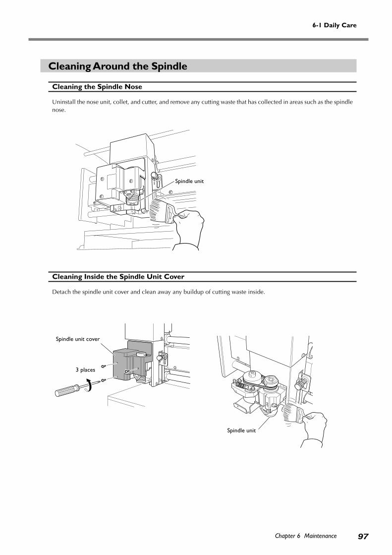
6-1 Daily Care
97Chapter 6 Maintenance
Cleaning Around the Spindle
Cleaning the Spindle Nose
Uninstall the nose unit, collet, and cutter, and remove any cutting waste that has collected in areas such as the spindlenose.
Cleaning Inside the Spindle Unit Cover
Detach the spindle unit cover and clean away any buildup of cutting waste inside.
Spindle unit cover
Spindle unit
3 places
Spindle unit
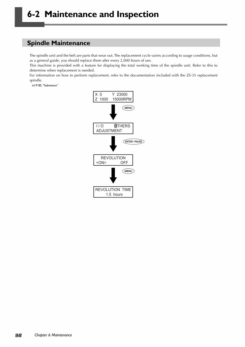
98 Chapter 6 Maintenance
6-2 Maintenance and Inspection
Spindle Maintenance
The spindle unit and the belt are parts that wear out. The replacement cycle varies according to usage conditions, butas a general guide, you should replace them after every 2,000 hours of use.This machine is provided with a feature for displaying the total working time of the spindle unit. Refer to this todetermine when replacement is needed.For information on how to perform replacement, refer to the documentation included with the ZS-35 replacementspindle.
☞ P. 85, "Submenus"

99
Chapter 7Troubleshooting

100 Chapter 7 Troubleshooting
7-1 Troubleshooting (Engraving)
The cutting-in depth is not uniform (when using the nose unit).
Try revising the cutting parameters as described below.
➢ Is automatic Z control set to"ON" with the lock lever atposition or ?
☞ P. 82, "The Position of the Lock Lever," p. 85, "Submenus"
➢ Is the cutter holder, the cutter-holder mounting screw, orthe collet loose?
☞ P. 56, "Cutter Installation Method 1"
➢ Is the X- and Y-axis feed rate too fast for the workpiece, oris the speed of spindle rotation too slow for it?
☞ P. 48, "Adjusting the Spindle Speed, " p. 77, "Adjusting the Cutter
Feed Rate During Engraving (Override)"
➢ Is the cutter worn? Try replacing the cutter.
➢ When the cutting-in depth is extremely shallow, the ef-fects of cutting waste can become large. Try using a cut-ter with a narrow blade width, along with increasing thecutting-in depth. Alternatively, use the vacuum adapterfor chip cleaning.
☞ P. 56, "Cutter Installation Method 1," p. 80,"Attaching the Vacuum
Adapter for Chip Cleaning"
The cutting-in depth is not uniform (when not using the nose unit).
Try revising the cutting parameters as described below.
➢ If possible, perform engraving while using the nose unit.
☞ P. 56, "Cutter Installation Method 1"
➢ Is the surface of the workpiece level? Revise the mountingmethod and other such factors to mount the workpieceso that its surface is level. Also, if the flatness or levelnessof the workpiece table is an issue, carry out surface level-ing for the workpiece table.
☞ P. 83, "Surface Leveling of the Workpiece Table"
➢ Is automatic Z control set to "ON" with the lock lever atposition ?
☞ P. 62, "Cutter Installation Method 2," p. 82, "The Position of the
Lock Lever"
➢ Is the cutter holder, tool retaining screw, or collet loose?
☞ P. 62, "Cutter Installation Method 2"
The cutter leaves tracks at places where cutting-in starts or where lines change direction.
Try revising the cutting parameters as described below.
➢ The spindle rotating speed is too slow with respect to thefeed rate. Try reducing the spindle speed.
☞ P. 48, "Adjusting the Spindle Speed"
➢ Is the cutter worn? Try replacing the cutter.
An engraved bottom surface is rough or burring remains.
Try revising the cutting parameters as described below.
➢ The spindle rotating speed is too slow with respect to thefeed rate. Try increasing the spindle speed or making thefeed rate slower.
☞ P. 48, "Adjusting the Spindle Speed," p. 77, "Adjusting the Cutter
Feed Rate During Engraving (Override)"
➢ Refasten the workpiece securely so that it does not comeloose or slip.
☞ P. 54, "Mounting a Workpiece"
➢ Try performing cutting a second time to finish the bottomsurface and remove any burring. Making the cutting-indepth about 0.02 to 0.05 mm deeper for the second passmay yield better results.
➢ Is the cutter worn? Try replacing the cutter.
➢ Check to make sure the cutter diameter matches the colletdiameter.
Engraved lines are uneven or wavy.
Try revising the cutting parameters as described below.
➢ The cutter holder, tool retaining screw, or collet is loose,and the cutter is out of control. Tighten securely.
☞ P. 56 through 71, "Cutter Installation Method 1" through "Cutter
Installation Method 4"
➢ Refasten the workpiece securely so that it does not comeloose or slip.
☞ P. 54, "Mounting a Workpiece"
➢ Check to make sure the cutter diameter matches the colletdiameter.
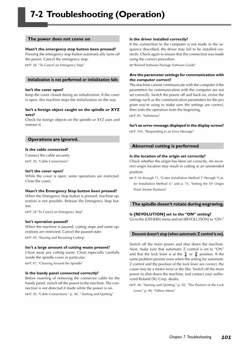
101Chapter 7 Troubleshooting
7-2 Troubleshooting (Operation)
The power does not come on
Hasn’t the emergency stop button been pressed?Pressing the emergency stop button automatically turns offthe power. Cancel the emergency stop.
☞ P. 38, “To Cancel an Emergency Stop”
Initialization is not performed or initialization fails
Isn’t the cover open?Keep the cover closed during an initialization. If the coveris open, this machine stops the initialization on the way.
Isn’t a foreign object caught on the spindle or XYZaxes?Check for foreign objects on the spindle or XYZ axes andremove it.
Operations are ignored.
Is the cable connected?Connect the cable securely.
☞ P. 30, "Cable Connections"
Isn’t the cover open?While the cover is open, some operations are restricted.Close the cover.
Hasn't the Emergency Stop button been pressed?When the Emergency Stop button is pressed, machine op-eration is not possible. Release the Emergency Stop but-ton.
☞ P. 38 "To Cancel an Emergency Stop"
Isn't operation paused?When the machine is paused, cutting stops and some op-erations are restricted. Cancel the paused state.
☞ P. 49, "Pausing and Resuming Cutting"
Isn't a large amount of cutting waste present?Clean away any cutting waste. Clean especially carefullyinside the spindle cover in particular.
☞ P. 97, "Cleaning Around the Spindle"
Is the handy panel connected correctly?Before inserting of removing the connector cable for thehandy panel, switch off the power to the machine. The con-nection is not detected if made while the power is on.
☞ P. 30, "Cable Connections," p. 40, " Starting and Quitting"
Is the driver installed correctly?If the connection to the computer is not made in the se-quence described, the driver may fail to be installed cor-rectly. Check again to ensure that the connection was madeusing the correct procedure.
☞ "Roland Software Package Software Guide"
Are the parameter settings for communication withthe computer correct?The machine cannot communicate with the computer if theparameters for communication with the computer are notset correctly. Switch the power off and back on, revise thesettings such as the communication parameters for the program you're using to make sure the settings are correct,then redo the operation from the beginning.
☞ P. 85, "Submenus"
Isn’t an error message displayed in the display screen?
☞ P. 104, “Responding to an Error Message”
Abnormal cutting is performed
Is the location of the origin set correctly?Check whether the origin has been set correctly. An incor-rect origin location may result in cutting at an unintended
position.
☞ P. 56 through 71, "Cutter Installation Method 1" through "Cut-
ter Installation Method 4," and p. 75, "Setting the XY Origin
Point (Home Position)"
The spindle doesn’t rotate during engraving.
Is [REVOLUTION] set to the “ON” setting?Go to the [OTHERS] menu and set [REVOLUTION] to “ON.”
Descent doesn’t stop (when automatic Z control is on).
Switch off the main power and shut down the machine.Next, make sure that automatic Z control is set to “ON”and that the lock lever is at the or position. If thesame problem persists even when the setting for automaticZ control and the position of the lock lever are correct, thecause may be a motor error or the like. Switch off the mainpower to shut down the machine, and contact your autho-rized Roland DG Corp. dealer.
☞ P. 40, "Starting and Quitting," p. 82, "The Position of the Lock
Lever," p. 90, "Others Menu"

7-2 Troubleshooting (Operation)
102 Chapter 7 Troubleshooting
The USB cable came loose during engraving.
If the machine succeeded in receiving all the engraving data,the engraving is carried out to the end of the operation. If themachine did not receive all the engraving data, engraving iscarried out for the portion received, and then the cutter risesand stops at a location away from the workpiece. The mes-sage [Command Not Recognized] may be displayed at thistime. If this happens, switch off the power and redo the op-eration from the beginning
☞ P. 40, "Starting and Quitting," p. 104, " Responding to an Error
Message"

103Chapter 7 Troubleshooting
7-3 Responding to a Message
These are the most common messages that appear on themachine’s display to prompt correct operation. They donot indicate any error. Follow the prompts and take actionaccordingly.
[Please close the cover]
Close the front cover.To ensure safety, the machine does not operate when thefront cover is open. However, operations using the move-ment buttons on the handy panel are possible while the coveris open.
[Stop performing COVER OPEN]
Close the front cover.The front cover was opened while the cutter was moving toa reference point, and so operation of the cutter stopped toensure safety.
[Pause On COVER OPEN]
Close the front cover.This is displayed in the following cases.
➢ Engraving data was sent while the front cover was open.
➢ "VIEW" was selected at the Pause menu, and the coverwas opened during movement to the VIEW position.
Closing the front cover returns the display to the Pause menu.
☞ P. 49 "Pausing and Resuming Cutting"
[Canceling data...]
This is displayed if engraving data is sent during initializa-tion. After processing to delete the data finishes, the mes-sage disappears. When the amount of data is large, it maytake some time for the message to disappear.
[Cannot repeat too big data]
This is displayed when an attempt was made using the Copymenu to perform engraving again, but the engraving datajust received was too large for the machine’s memory capac-ity. After three seconds this message disappears and the screenreturns to the original menu.
[Cannot repeat buffer empty]
This is displayed when an attempt is made using the Copymenu to perform engraving again while no engraving data issaved in the machine. After three seconds this message dis-appears and the screen returns to the original menu.
☞ P. 78 "Executing Repeated Cutting"
[Turn the AUTO Z CONTROL off]
This was displayed because an attempt was made to set theZ0, Z1, or Z2 position even though automatic Z control ison.After three seconds this message disappears and the screenreturns to the original menu.
☞ P. 92 "Origin-setting Menu"

104 Chapter 7 Troubleshooting
7-4 Responding to an Error Message
This describes the error messages that may appear on themachine’s display screen, and how to take action to rem-edy the problem. If the action described here does notcorrect the problem, or if an error message not describedhere appears, contact your authorized Roland DG Corp.dealer.
[Emergency Stop COVER OPEN]
An emergency stop occurred because the front coverwas opened while the spindle was rotating.Operation cannot be continued. Switch the power off andback on, then redo the operation from the start.
☞ P. 40, "Starting and Quitting"
[Emergency Stop S-overload[*]]
An emergency stop occurred because of a spindle-motor error.This is caused by prolonged high load on the motor or byexcessive torque being applied momentarily. Resuming is notpossible. Switch the power off and back on, revise the cut-ting parameters, then redo the operation from the start.If this message persists even after revising the cutting param-eters, contact your authorized Roland DG Corp. dealer.Note: The kind of load applied is indicated as “S” (short), “L”(long), “P” (peak), or “T” (temperature).
☞ P. 40, "Starting and Quitting"
[Emergency Stop Z AXIS error]
An emergency pause occurred because Z-axis descentfailed to stop.Resuming is not possible. The spindle head may be lockedwhile automatic Z control is set to "ON." Switch the poweroff and back on, then check the position of the lock lever forthe spindle head. After checking, redo the operation fromthe beginning.If this message continues to appear, contact your authorizedRoland DG Corp. dealer.
☞ P. 40, "Starting and Quitting," p. 82, "The Position of the Lock
Lever," and p. 108, " Examples of Settings for Cutting Parameters"
[Emergency Stop RPM error]
An emergency stop occurred because rotation of thespindle failed to reach the specified rpm.Operation cannot be continued. The cause is a motor erroror the like. Switch off the power and contact your autho-rized Roland DG Corp. dealer.
☞ P. 41, "Shutdown"
[Cannot find *- LIMIT SW]
An emergency stop occurred because initializationfailed.Switch the power off, remove any cutting waste or other ob-structions impeding operation of the spindle head, then redothe operation from the start. If the message persists even af-ter redoing the operation from the beginning, contact yourauthorized Roland DG Corp. dealer.* "X," "Y," or "Z"
☞ P. 40, "Starting and Quitting"
[I/O Err:Framing/Parity Error]
This is displayed when the parameter settings forcommunication with the computer are unsuitable.Pressing pauses the machine. Because unin-tended operation may occur, we recommend using the“pause” menu displayed on the screen to select “STOP” andquit operation.Revise the communication parameters on the machine andthe computer (the settings for baud rate, parity, number ofstop bits, and data bit length). When a serial connection isused, this error message may appear if the computer is re-started while the machine is powered up.
☞ P. 50, "Stopping Cutting," p. 85, "Submenus"
[I/O Err:Buffer Overflow]
The machine’s memory experienced an overflow.Pressing pauses the machine. Because unin-tended operation may occur, we recommend using the“pause” menu displayed on the screen to select “STOP” andquit operation.Possible causes include unsuitable communication param-eters for a serial connection. Revise the communication pa-rameters on the machine and the computer (the settings forbaud rate, parity, number of stop bits, and data bit length).
☞ P. 50, "Stopping Cutting," p. 85, "Submenus"

7-3 Responding to an Error Message
105Chapter 7 Troubleshooting
[Command Not Recognized]
An emergency stop occurred because the machinereceived a command that could not be interpretedfrom the computer.Pressing pauses the machine. Because unin-tended operation may occur, we recommend using the“pause” menu displayed on the screen to select “STOP” andquit operation.This is caused by program settings that do not match themachine’s command set. Check the program’s settings andother values, and redo the operation from the beginning. Thismessage may also be displayed when a faulty connection inthe connector cable to the computer occurs. Eliminate thecauses, then redo the operation from the beginning. If thismessage continues to appear, contact your authorized RolandDG Corp. dealer.
☞ P. 40, "Starting and Quitting," p. 50, "Stopping Cutting"
[Wrong Number of Parameters]
The number of parameters for a command receivedfrom the computer was incorrect.Pressing pauses the machine. Because unin-tended operation may occur, we recommend using the“pause” menu displayed on the screen to select “STOP” andquit operation.Check to make sure the program you’re using is compatiblewith the machine.
☞ P. 50, "Stopping Cutting"
[Bad Parameter]
The parameter for a command received from thecomputer was out of range.Pressing pauses the machine. Because unin-tended operation may occur, we recommend using the“pause” menu displayed on the screen to select “STOP” andquit operation.Check to make sure the program you’re using is compatiblewith the machine.
☞ P. 50, "Stopping Cutting"

106

107
Chapter 8Appendix
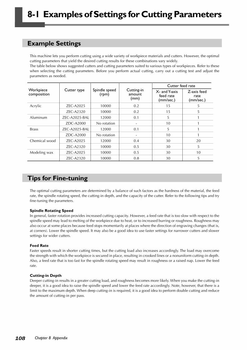
108 Chapter 8 Appendix
8-1 Examples of Settings for Cutting Parameters
Example Settings
This machine lets you perform cutting using a wide variety of workpiece materials and cutters. However, the optimalcutting parameters that yield the desired cutting results for these combinations vary widely.The table below shows suggested cutters and cutting parameters suited to various types of workpieces. Refer to thesewhen selecting the cutting parameters. Before you perform actual cutting, carry out a cutting test and adjust theparameters as needed.
Tips for Fine-tuning
The optimal cutting parameters are determined by a balance of such factors as the hardness of the material, the feedrate, the spindle rotating speed, the cutting-in depth, and the capacity of the cutter. Refer to the following tips and tryfine-tuning the parameters.
Spindle Rotating SpeedIn general, faster rotation provides increased cutting capacity. However, a feed rate that is too slow with respect to thespindle speed may lead to melting of the workpiece due to heat, or to increased burring or roughness. Roughness mayalso occur at some places because feed stops momentarily at places where the direction of engraving changes (that is,at corners). Lower the spindle speed. It may also be a good idea to use faster settings for narrower cutters and slowersettings for wider cutters.
Feed RateFaster speeds result in shorter cutting times, but the cutting load also increases accordingly. The load may overcomethe strength with which the workpiece is secured in place, resulting in crooked lines or a nonuniform cutting-in depth.Also, a feed rate that is too fast for the spindle rotating speed may result in roughness or a raised nap. Lower the feedrate.
Cutting-in DepthDeeper cutting-in results in a greater cutting load, and roughness becomes more likely. When you make the cutting-indeeper, it is a good idea to raise the spindle speed and lower the feed rate accordingly. Note, however, that there is alimit to the maximum depth. When deep cutting-in is required, it is a good idea to perform double cutting and reducethe amount of cutting-in per pass.
Workpiececomposition
Acrylic
Aluminum
Brass
Chemical wood
Modeling wax
Cutter type
ZEC-A2025
ZEC-A2320
ZEC-A2025-BAL
ZDC-A2000
ZEC-A2025-BAL
ZDC-A2000
ZEC-A2025
ZEC-A2320
ZEC-A2025
ZEC-A2320
Spindle speed(rpm)
10000
10000
12000
No rotation
12000
No rotation
12000
10000
10000
10000
Cutting-inamount(mm)
0.2
0.2
0.1
-
0.1
-
0.4
0.5
0.5
0.8
Cutter feed rateX- and Y-axis
feed rate(mm/sec.)
15
15
5
10
5
10
30
30
30
30
Z-axis feedrate
(mm/sec.)5
5
1
1
1
1
20
5
10
5

109Chapter 8 Appendix
8-2 Location of Power Rating and Serial Number Label
Power RatingUse an electrical outlet that meets the requirementsfor voltage and frequency given here.Provide a power supply whose amperage is 1.3 Aor higher (for 100 to 120 V) or 0.6 A or higher (for220 to 240 V).
Serial NumberThis is required when you seek maintenance or sup-port. Never peel off.

110 Chapter 8 Appendix
8-3 Interface Specifications
Serial Connector
RS-232C specification
Asynchronous, duplex data transmission
4800, 9600, 19200, 38400
Odd, Even, None
7 or 8 bits
1 or 2 bits
Hardware or Xon/Xoff
StandardTransmission methodTransmission speedParity checkData bitsStop bits
Handshake
Serial connector (RS-232C)
NC
NC
NC
NC
NC
DTR
NC
NC
NC
NC
NC
NC
NC
NC
NC
NC
NC
NC
SG
DSR
CTS
RTS
RXD
TXD
FG
Terminalnumber
25
24
23
22
21
20
19
18
17
16
15
14
13
12
11
10
9
8
7
6
5
4
3
2
1
Pin connectionSignal
numberSignal
number
1
14
13
25
XY-RS-34/14 cable connection
D-sub 9 pin D-sub 25 pin

8-2 Interface Specifications
111Chapter 8 Appendix
Expansion Connector
This circuit works during spindle motor rotation.
Note: We are not responsible for devices connected to this connector.
◆ Be sure to use the connector within the ratedrange shown above.
◆ Do not apply an additional voltage to the con-nector.
◆ Do not short-circuit the connector and earthing.
Do not use the terminal 3. Use onlythe 1 and 2 terminals.
Pin 1 Pin 2Connec-tor
+24 V
Ic (max) = 150mA
Adaptive Plug
Use a three-contact plug that meets thesize requirements above.
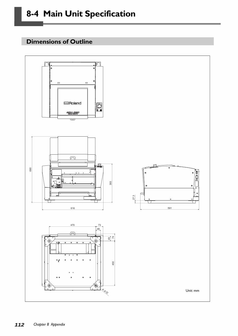
112 Chapter 8 Appendix
8-4 Main Unit Specification
Dimensions of Outline
Unit: mm
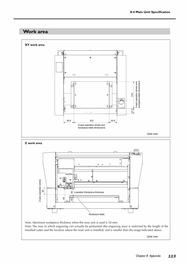
8-4 Main Unit Specification
113Chapter 8 Appendix
Work area
XY work area
Z work area
Note: Maximum workpiece thickness when the nose unit is used is 38 mm.Note: The area in which engraving can actually be performed (the engraving area) is restricted by the length of theinstalled cutter and the location where the nose unit is installed, and is smaller than the range indicated above.
Unit: mm
80
Y-a
xis
opera
tion s
troke a
nd
work
pie
ce-t
able
dim
ensio
ns
Unit: mm

8-4 Main Unit Specification
114 Chapter 8 Appendix
Workpiece-table Installation-area Dimensional Drawing
Unit: mm
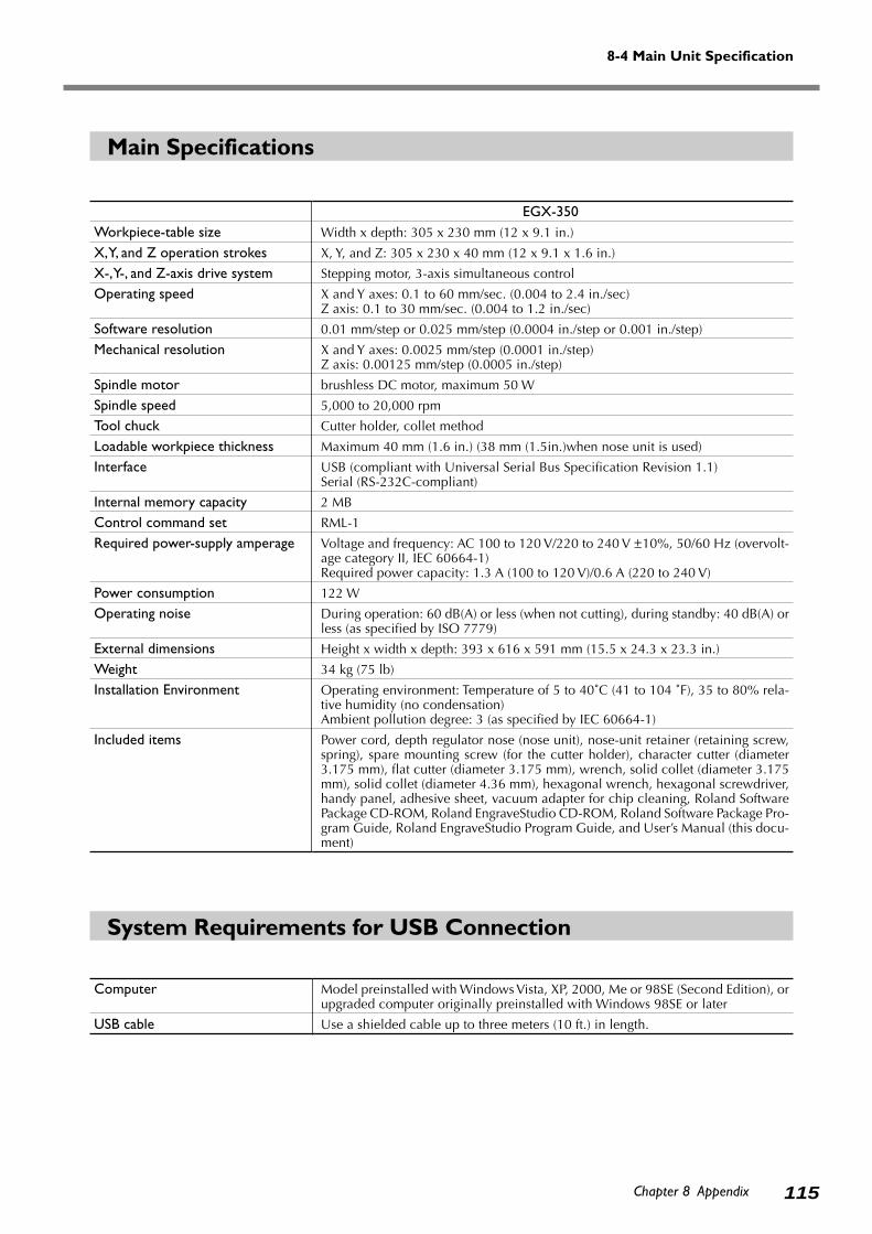
8-4 Main Unit Specification
115Chapter 8 Appendix
Main Specifications
Workpiece-table sizeX, Y, and Z operation strokesX-, Y-, and Z-axis drive systemOperating speed
Software resolutionMechanical resolution
Spindle motorSpindle speedTool chuckLoadable workpiece thicknessInterface
Internal memory capacityControl command setRequired power-supply amperage
Power consumptionOperating noise
External dimensionsWeightInstallation Environment
Included items
EGX-350Width x depth: 305 x 230 mm (12 x 9.1 in.)
X, Y, and Z: 305 x 230 x 40 mm (12 x 9.1 x 1.6 in.)
Stepping motor, 3-axis simultaneous control
X and Y axes: 0.1 to 60 mm/sec. (0.004 to 2.4 in./sec)Z axis: 0.1 to 30 mm/sec. (0.004 to 1.2 in./sec)
0.01 mm/step or 0.025 mm/step (0.0004 in./step or 0.001 in./step)
X and Y axes: 0.0025 mm/step (0.0001 in./step)Z axis: 0.00125 mm/step (0.0005 in./step)
brushless DC motor, maximum 50 W
5,000 to 20,000 rpm
Cutter holder, collet method
Maximum 40 mm (1.6 in.) (38 mm (1.5in.)when nose unit is used)
USB (compliant with Universal Serial Bus Specification Revision 1.1)Serial (RS-232C-compliant)
2 MB
RML-1
Voltage and frequency: AC 100 to 120 V/220 to 240 V ±10%, 50/60 Hz (overvolt-age category II, IEC 60664-1)Required power capacity: 1.3 A (100 to 120 V)/0.6 A (220 to 240 V)
122 W
During operation: 60 dB(A) or less (when not cutting), during standby: 40 dB(A) orless (as specified by ISO 7779)
Height x width x depth: 393 x 616 x 591 mm (15.5 x 24.3 x 23.3 in.)
34 kg (75 lb)
Operating environment: Temperature of 5 to 40˚C (41 to 104 ˚F), 35 to 80% rela-tive humidity (no condensation)Ambient pollution degree: 3 (as specified by IEC 60664-1)
Power cord, depth regulator nose (nose unit), nose-unit retainer (retaining screw,spring), spare mounting screw (for the cutter holder), character cutter (diameter3.175 mm), flat cutter (diameter 3.175 mm), wrench, solid collet (diameter 3.175mm), solid collet (diameter 4.36 mm), hexagonal wrench, hexagonal screwdriver,handy panel, adhesive sheet, vacuum adapter for chip cleaning, Roland SoftwarePackage CD-ROM, Roland EngraveStudio CD-ROM, Roland Software Package Pro-gram Guide, Roland EngraveStudio Program Guide, and User’s Manual (this docu-ment)
System Requirements for USB Connection
Computer
USB cable
Model preinstalled with Windows Vista, XP, 2000, Me or 98SE (Second Edition), orupgraded computer originally preinstalled with Windows 98SE or later
Use a shielded cable up to three meters (10 ft.) in length.

116

117

118

119

120


R4-081124