0000-00 the e-coupling ecu monitors the can communication
TRANSCRIPT

The E-coupling ECU monitors the CAN communication signal and sets a diagnostic trouble code (DTC) if it is not normal.
DTC Detection condition Symptom
U0001 CAN communication error: bus OFF
Warning lamp ONCoupling torque set to 0 NmCAN message transmission stopped (keeps attempting to restore)
1. 2. 3.
1 0000-00

1. Component Location
2. Component Description
The CAN topology communicate with system units. There are 2 types of CAN communication according to the communication speed: P-CAN and B-CAN. Communication speed of the former is faster than that of the latter.While the SKM, instrument cluster, BCM, and diagnostic connectors use P-CAN and B-CAN communications to communicate with other units, Terminating resistors are installed in ECU and instrument cluster.
20000-00

1. Partial Circuit Diagram (G16DF )
3 0000-00

(D16DTF )
40000-00

2. Connector Appearance
5 0000-00

60000-00

1. Troubleshooting
Connect the DSM to the OBD2 connector.Turn the ignition switch to the "ON" position.Clear any diagnostic trouble code (DTC).
1) 2) 3)
If the DTC occurs persistently, refer to the procedure described in the section "Check method".
7 0000-00

1. Check CAN Communication Line (P_CAN)
If the resistance cannot be measure, inspect the unit or check the wiring for open circuit.
Turn the ignition switch to the "OFF" position.Measure the terminal resistance between the terminals No. 6 P_CAN HIGH and No. 14 P_CAN LOW on the self-diagnosis connector according to each measuring condition.Measurement condition- With connector installed (measurement 1)- With ECU connector removed (measurement 2)- With instrument cluster connector removed (measurement 3)
1)
2)
3)
Measuring resistance
Tester connection (to wiring) Specified value
Terminal No. 6 ↔ Terminal No. 14
Approx. 60 Ω (measurement 1)
Approx. 120 Ω (measurement 2)
Approx. 120 Ω (measurement 3)
The ECU and instrument cluster have the terminal resistance of 120 Ω and
the terminal resistance of about 60 Ω is measured with the ECU and
instrument cluster connectors connected.
80000-00

2. Check CAN Communication Line For Short
Repair the CAN communication line which has a short circuit.
Turn the ignition switch to the "OFF" position.Disconnect all unit connectors which communicate through the CAN communication line.Measure the resistance between the terminals No. 6 P_CAN HIGH and No. 14 P_CAN LOW on the self-diagnosis connector.
1)
2)
3)
Measuring resistance
Tester connection (to wiring) Specified value
Terminal No. 6 ↔ Terminal No. 14 Infinite Ω
3. Check CAN Communication Line For Short Circuit (GND)
Repair the CAN communication line which has a short circuit to ground.
Turn the ignition switch to the "OFF" position.Disconnect all unit connectors which communicate through the CAN communication line.Measure the resistances between the terminals No. 6 P_CAN HIGH and No. 14 P_CAN LOW on the self-diagnosis connector and body ground.
1)
2)
3)
Measuring resistance
Tester connection (to wiring) Specified value
Terminal No. 6 ↔ BodyInfinite Ω
Terminal No. 14 ↔ Body
9 0000-00

4. Check CAN Communication Line For Open
Repair the CAN communication line which has an open circuit.
Turn the ignition switch to the "OFF" position.Disconnect all unit connectors which communicate through the CAN communication line.Measure the resistance between the terminal No. 6 P_CAN HIGH on the self-diagnosis connector and P_CAN HIGH terminal on each unit.Measure the resistance between the terminal No. 14 P_CAN LOW on the self-diagnosis connector and P_CAN LOW terminal on each unit.
1)
2)
3)
4)
Measuring voltage
Tester connection (to wiring) Specified value
Terminal No. 6 ↔ P_CAN HIGH terminal on
each unit Approx. 0 Ω
Terminal No. 14 ↔ P_CAN LOW terminal on
each unit
5. Final Service Check
This is to check the serviced item again for the last time after the service is completed. Erase DTC(s) again on the diagnostic device.Test drive the vehicle and check the vehicle has recovered its normal condition.
- - -
Perform the inspection procedures again after replacing the problematic unit.
Service completed (System normal)
100000-00

DTC Detection condition Symptom
U0121
Wheel speed signal missing in 3 consecutive times or for 250 ms
Coupling torque limit, coupling opening request signal missing in 3 consecutive times or for 250 ms
U0415
Implausible wheel speed signal is received
Implausible signal for coupling torque limit is received
The E-coupling ECU monitors the CAN communication signal and sets a diagnostic trouble code (DTC) if it is not normal.
Warning lamp ONDefault value for wheel speed signal replaced by 0 rpmChanged to 2WD mode
1. 2. 3.
Output torque request by coupling control replaced by 3000 NmOther signals overridden
1. 2.
Warning lamp ONDefault value for wheel speed signal replaced by 0 rpmChanged to 2WD mode
1. 2. 3.
Output torque request by coupling control replaced by 3000 NmOther signals overridden
1. 2.
1 0000-00

1. Component Location
2. Component Description
The CAN topology communicate with system units. There are 2 types of CAN communication according to the communication speed: P-CAN and B-CAN. Communication speed of the former is faster than that of the latter.While the SKM, instrument cluster, BCM, and diagnostic connectors use P-CAN and B-CAN communications to communicate with other units, Terminating resistors are installed in ECU and instrument cluster.
20000-00

1. Partial Circuit Diagram (G16DF )
3 0000-00
(D16DTF )
40000-00

2. Connector Appearance
5 0000-00

60000-00

1. Troubleshooting
Connect the DSM to the OBD2 connector.Turn the ignition switch to the "ON" position.Clear any diagnostic trouble code (DTC).
1) 2) 3)
Any DTC related to CAN communication should be checked and rectified first.If any DTC occurs at other unit, perform the diagnosis on the unit.
--
2. Sensor Output
Connect the DSM to the OBD2 connector.Turn the ignition switch to the "ON" position.Check the change in sensor reading while driving the vehicle.Check the item "Wheel speed sensor".
1) 2) 3) 4)
Item Specification
Wheel Speeds Left Front
Varies with change in vehicle speedWheel Speeds Right Front
Wheel Speeds Left Rear
Wheel Speeds Right Rear
7 0000-00

The E-coupling ECU monitors the CAN communication signal and sets a diagnostic trouble code (DTC) if it is not normal.
DTC Detection condition Symptom
U0101
Gear position signal missing in 3 consecutive times or for 250 ms
Gear lever position signal missing in 3 consecutive times or for 250 ms
U0402
Invalid gear position signal is received
Invalid gear lever position signal is received
Default value for gear position replaced by 1stShift gear stage estimated by torque
1.
2.
Default value for shift lever position replaced by "Reverse"PRNDL logic stopped
1.
2.
Default value for gear position replaced by 1stShift gear stage estimated by torque
1.
2.
Default value for shift lever position replaced by "Reverse"PRNDL logic stopped
1.
2.
1 0000-00

1. Component Location
2. Component Description
The CAN topology communicate with system units. There are 2 types of CAN communication according to the communication speed: P-CAN and B-CAN. Communication speed of the former is faster than that of the latter.While the SKM, instrument cluster, BCM, and diagnostic connectors use P-CAN and B-CAN communications to communicate with other units, Terminating resistors are installed in ECU and instrument cluster.
20000-00

1. Partial Circuit Diagram (G16DF )
3 0000-00

(D16DTF )
40000-00

2. Connector Appearance
5 0000-00

60000-00

1. Troubleshooting
Connect the DSM to the OBD2 connector.Turn the ignition switch to the "ON" position.Clear any diagnostic trouble code (DTC).
1) 2) 3)
2. Sensor Output
Connect the DSM to the OBD2 connector.Turn the ignition switch to the "ON" position.Check the change in data value while driving the vehicle.Check the item "Trans Gear".
1) 2) 3) 4)
Item Specification
Trans Gear Varies with change in vehicle speed
Any DTC related to CAN communication should be checked and rectified first.If any DTC occurs at other unit, perform the diagnosis on the unit.
--
7 0000-00

DTC Detection condition Symptom
U0155
Ambient temperature signal missing in 3 consecutive times or for 250 ms
Default value for ambient temperature signal replaced by 21
M/T gear position or parking brake signal missing in 3 consecutive times or for 250 ms
U0423
Implausible ambient temperature signal received
Default value for ambient temperature signal replaced by 21
Implausible M/T gear position or parking brake signal received
The E-coupling ECU monitors the CAN communication signal and sets a diagnostic trouble code (DTC) if it is not normal.
Default value for M/T gear position replaced by "Reverse"Parking brake logic stopped
1.
2.
Default value for M/T gear position replaced by "Reverse"Parking brake logic stopped
1.
2.
1 0000-00

1. Component Location
2. Component Description
The CAN topology communicate with system units. There are 2 types of CAN communication according to the communication speed: P-CAN and B-CAN. Communication speed of the former is faster than that of the latter.While the SKM, instrument cluster, BCM, and diagnostic connectors use P-CAN and B-CAN communications to communicate with other units, Terminating resistors are installed in ECU and instrument cluster.
20000-00

1. Partial Circuit Diagram (G16DF )
3 0000-00

(D16DTF )
40000-00

2. Connector Appearance
5 0000-00

60000-00

1. Troubleshooting
Connect the DSM to the OBD2 connector.Turn the ignition switch to the "ON" position.Clear any diagnostic trouble code (DTC).
1) 2) 3)
2. Sensor Output
Connect the DSM to the OBD2 connector.Turn the ignition switch to the "ON" position.Check the data values while moving the gear position.Check the items "Trans In Reverse, Trans In Neutral".
1) 2) 3) 4)
Item Conditions Specification
Trans In Reverse Gear in "R" position R
Trans In Neutral Gear in "N" position N
Any DTC related to CAN communication should be checked and rectified first.If any DTC occurs at other unit, perform the diagnosis on the unit.
--
7 0000-00

DTC Detection condition Symptom
U0100
Accelerator pedal position signal missing in 3 consecutive times or for 250 ms
Default value for throttle valve position replaced by 0%
Engine rpm or clutch pedal signal missing in 3 consecutive times or for 250 ms
Engine torque signal missing in 3 consecutive times or for 250 ms
Default value for engine torque replaced by 1,000 Nm
M/T neutral or engine running signal missing in 3 consecutive times or for 250 ms
Intake air temperature signal missing in 3 consecutive times or for 250 ms
Default value for intake air temperature signal replaced by 21
Engine and transmission specification code signal missing in 3 consecutive times or for 250 ms
The E-coupling ECU monitors the CAN communication signal and sets a diagnostic trouble code (DTC) if it is not normal.
Default value for engine RPM replace by 10,000 rpmDefault value for clutch signal replaced by "Active"
1.
2.
Default value for neutral signal replaced by "Inactive" (M/T)Default value for engine status replaced by engine running, cranking and IGN ON
1.
2.
Default value for engine specification replaced by D20DTFDefault value for transmission specification replaced by DSI6AT
1.
2.
1 0000-00
DTC Detection condition Symptom
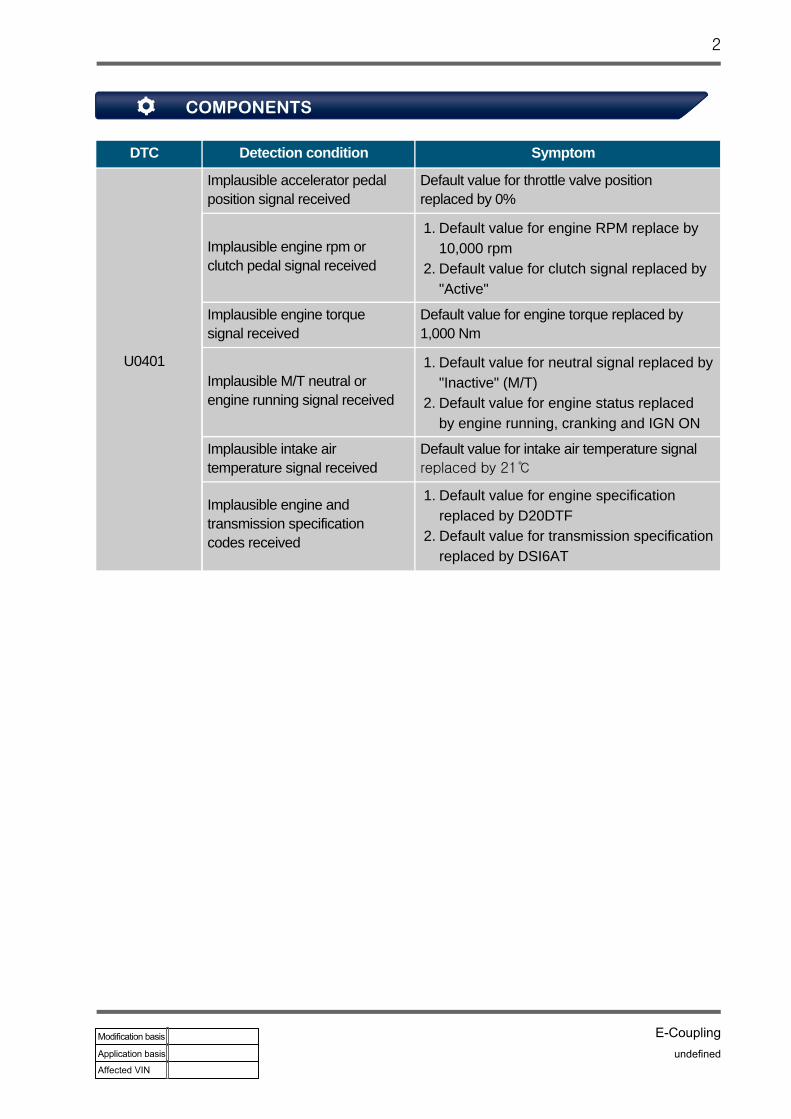
U0401
Implausible accelerator pedal position signal received
Default value for throttle valve position replaced by 0%
Implausible engine rpm or clutch pedal signal received
Implausible engine torque signal received
Default value for engine torque replaced by 1,000 Nm
Implausible M/T neutral or engine running signal received
Implausible intake air temperature signal received
Default value for intake air temperature signal replaced by 21
Implausible engine and transmission specification codes received
Default value for engine RPM replace by 10,000 rpmDefault value for clutch signal replaced by "Active"
1.
2.
Default value for neutral signal replaced by "Inactive" (M/T)Default value for engine status replaced by engine running, cranking and IGN ON
1.
2.
Default value for engine specification replaced by D20DTFDefault value for transmission specification replaced by DSI6AT
1.
2.
20000-00

1. Component Location
2. Component Description
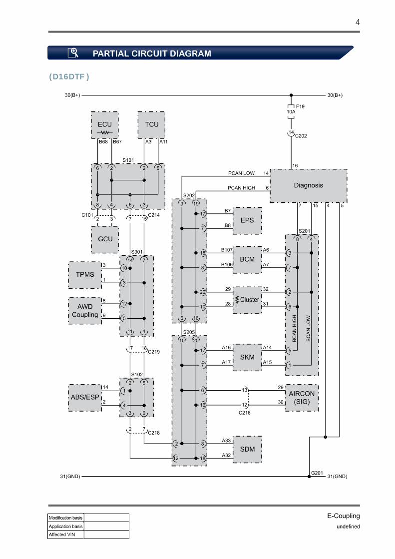
The CAN topology communicate with system units. There are 2 types of CAN communication according to the communication speed: P-CAN and B-CAN. Communication speed of the former is faster than that of the latter.While the SKM, instrument cluster, BCM, and diagnostic connectors use P-CAN and B-CAN communications to communicate with other units, Terminating resistors are installed in ECU and instrument cluster.
3 0000-00

1. Partial Circuit Diagram (G16DF )
40000-00

(D16DTF )
5 0000-00

2. Connector Appearance
60000-00

7 0000-00

1. Troubleshooting
Connect the DSM to the OBD2 connector.Turn the ignition switch to the "ON" position.Clear any diagnostic trouble code (DTC).
1) 2) 3)
2. Sensor Output
Connect the DSM to the OBD2 connector.Run the engine.Check the item "Engine Torque, Variant" on the diagnostic device.
1) 2) 3)
Item Specification
Engine Torque Below 1547.5 Nm
Variant Check if the engine and transmission specification codes match the vehicle.
Any DTC related to CAN communication should be checked and rectified first.If any DTC occurs at other unit, perform the diagnosis on the unit.
--
80000-00

The E-coupling ECU monitors the coil control line signal and sets a diagnostic trouble code (DTC) if it is not normal.
DTC Detection condition Symptom
P1728 Coupling coil control line is open
P1729 Coupling coil control line is shorted to power
P1730 Coupling coil control line is shorted to ground
Warning lamp ONCoupling torque set to 0 NmChanged to 2WD mode
1. 2. 3.
1 0000-00

1. Component Location
2. Component Description
The EMCD solenoid is in the E-coupling case and can't be removed separately.The E-coupling ECU controls the EMCD solenoid's current depending on the vehicle condition to adjust the torque to the rear axle.
20000-00

1. Partial Circuit Diagram
2. Connector Appearance
3 0000-00
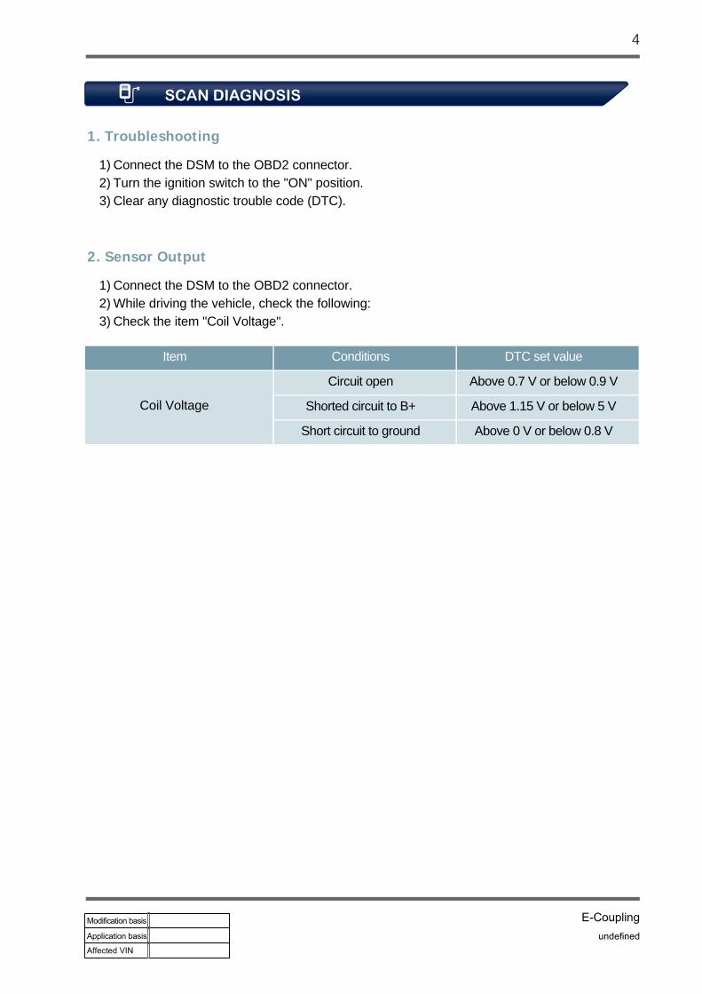
1. Troubleshooting
Connect the DSM to the OBD2 connector.Turn the ignition switch to the "ON" position.Clear any diagnostic trouble code (DTC).
1) 2) 3)
2. Sensor Output
Connect the DSM to the OBD2 connector.While driving the vehicle, check the following:Check the item "Coil Voltage".
1) 2) 3)
Item Conditions DTC set value
Circuit open Above 0.7 V or below 0.9 V
Shorted circuit to B+ Above 1.15 V or below 5 V
Short circuit to ground Above 0 V or below 0.8 V
Coil Voltage
40000-00

2. Check Control Wire For Short Circuit
Turn the ignition switch to the "OFF" position.Disconnect the E-coupling unit connector and EMCD connector.Measure the resistance between the control wire terminal No. 2 and ground wire terminal No. 1 of the EMCD wiring connector.
1) 2)
3)
Measuring resistance
Tester connection (to wiring) Specification
Terminal No. 2 ↔ Body Infinite Ω
Check the control wire for short circuit and repair as necessary.
1. Check Control Wire For Short Circuit To Ground
Turn the ignition switch to the "OFF" position.Disconnect the E-coupling unit connector and EMCD connector.Measure the resistance between the control wire terminal No. 2 of the EMCD wiring connector and the body ground.
1) 2)
3)
Measuring resistance
Tester connection (to wiring) Specification
Terminal No. 1 ↔ Terminal No. 2 Infinite Ω
Check the control wire for short circuit and repair as necessary.
5 0000-00

4. Check Wiring For Open Circuit
Turn the ignition switch to the "OFF" position.Disconnect the E-coupling unit connector and EMCD connector.Measure the resistance between the E-coupling wiring connector and EMCD wiring connector.
1) 2)
3)
Measuring voltage
Tester connection (to wiring) Specification
Terminal No. 2 ↔ Body Approx. 0 V
Check the control wire for short circuit and repair as necessary.
3. Check Control Wire For Short Circuit To Power
Turn the ignition switch to the "OFF" position.Disconnect the E-coupling unit connector and EMCD connector.Turn the ignition switch to the "ON" position.Measure the voltage between the control wire terminal No. 2 of the EMCD wiring connector and the body ground.
1) 2)
3) 4)
Measuring resistance
Tester connection(EMC ↔ E-coupling unit)
Specification
Terminal No. 1 ↔ Terminal No. 24Approx. 0 Ω
Terminal No. 2 ↔ Terminal No. 11
Check the EMCD wiring for open circuit and repair as necessary.
60000-00

Measuring resistance
Tester connection (component side) Specification
Terminal No. 1 ↔ Terminal No. 2 Approx. 2.2 Ω
Replace the EMCD part.
5. Checking Component
Turn the ignition switch to the "OFF" position.Disconnect the EMCD connector.Measure the resistance between the EMCD connectors No. 1 and 2.
1) 2) 3)
6. Final Service Check-up
Perform the inspection procedures again after replacing the E-coupling unit.
This is to check the serviced item again for the last time after the service is completed. Erase DTC(s) again on the diagnostic device.Test drive the vehicle and check the vehicle has recovered its normal condition.
- - -
Service completed (System normal)
7 0000-00
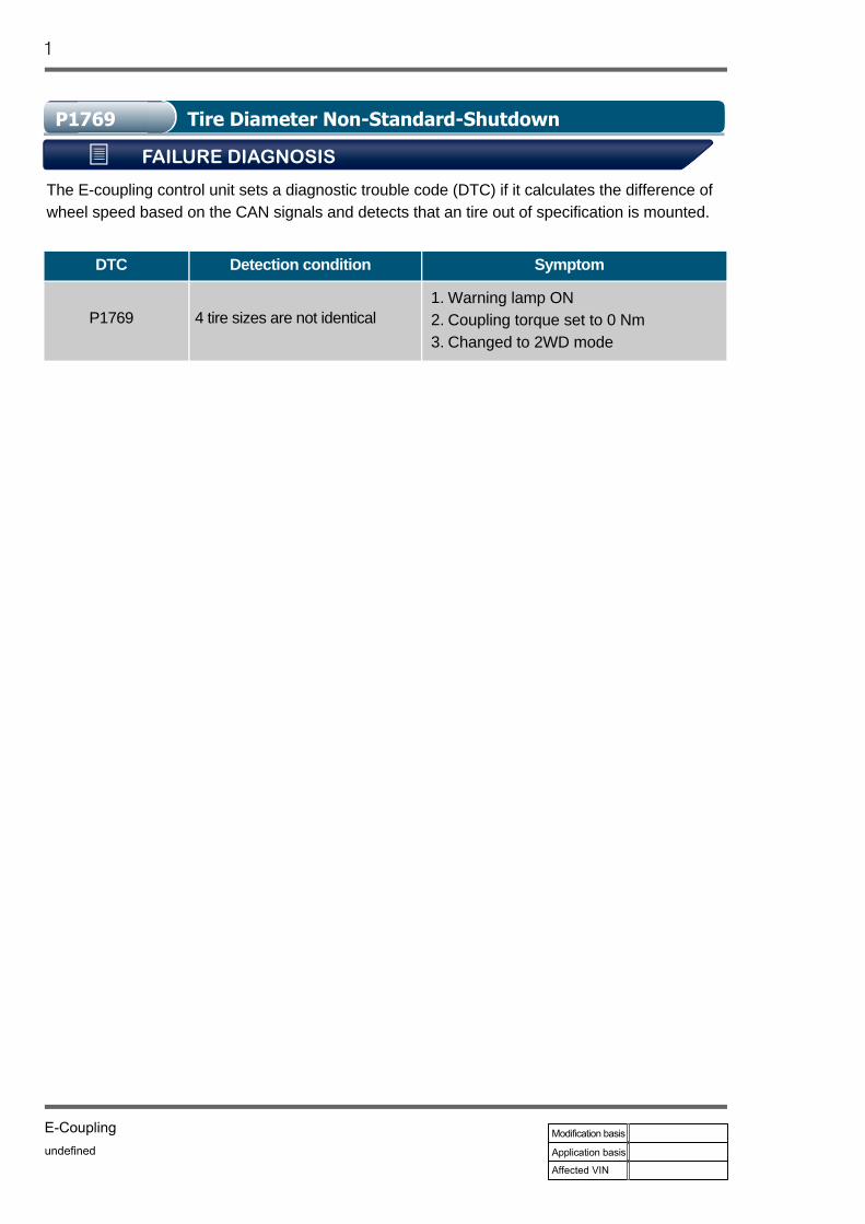
The E-coupling control unit sets a diagnostic trouble code (DTC) if it calculates the difference of wheel speed based on the CAN signals and detects that an tire out of specification is mounted.
DTC Detection condition Symptom
P1769 4 tire sizes are not identicalWarning lamp ONCoupling torque set to 0 NmChanged to 2WD mode
1. 2. 3.
1 0000-00

1. Component Location
2. Component Description
When a tire out of specification such as the spare tire is installed, the E-coupling control unit calculates the difference between the CAN signals on wheel speed to detect that the wrong tire has been installed. At this time, it reduces the torque to the rear wheels and sets a diagnostic trouble code (DTC).
20000-00
1. Troubleshooting
Connect the DSM to the OBD2 connector.Turn the ignition switch to the "ON" position.Clear any diagnostic trouble code (DTC).
1) 2) 3)
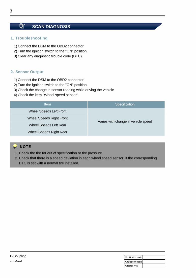
2. Sensor Output
Connect the DSM to the OBD2 connector.Turn the ignition switch to the "ON" position.Check the change in sensor reading while driving the vehicle.Check the item "Wheel speed sensor".
1) 2) 3) 4)
Item Specification
Wheel Speeds Left Front
Varies with change in vehicle speedWheel Speeds Right Front
Wheel Speeds Left Rear
Wheel Speeds Right Rear
Check the tire for out of specification or tire pressure.Check that there is a speed deviation in each wheel speed sensor, if the corresponding DTC is set with a normal tire installed.
1. 2.
3 0000-00

The E-coupling ECU sets a diagnostic trouble code (DTC) if the coupling becomes too hot.
DTC Detection condition Symptom
P1771 Coupling overheatsWarning lamp (blinks and stays on)Coupling torque set to 0 NmChanged to 2WD mode
1. 2. 3.
1 0000-00

1. Component Location
2. Component Description
The E-coupling control unit calculates the E-coupling's slip (input/output speed), ambient temperature, magnetic coil resistance and etc. to protect the oil and clutch plate from being overheated. If the E-coupling get too hot, the E-coupling control unit reduces the torque to the rear wheels and sets a diagnostic trouble code (DTC).
20000-00

1. Troubleshooting
Connect the DSM to the OBD2 connector.Turn the ignition switch to the "ON" position.Clear any diagnostic trouble code (DTC).
1) 2) 3)
If the DTC occurs persistently, replace the E-coupling assembly.
3 0000-00

The E-coupling ECU monitors the battery supply voltage and sets a diagnostic trouble code (DTC) if it is not normal.
DTC Detection condition Symptom
P3003 Battery supply voltage is lower than 8 V or above 17 V
Warning lamp ONCoupling torque set to 0 NmChanged to 2WD mode
1. 2. 3.
1 0000-00
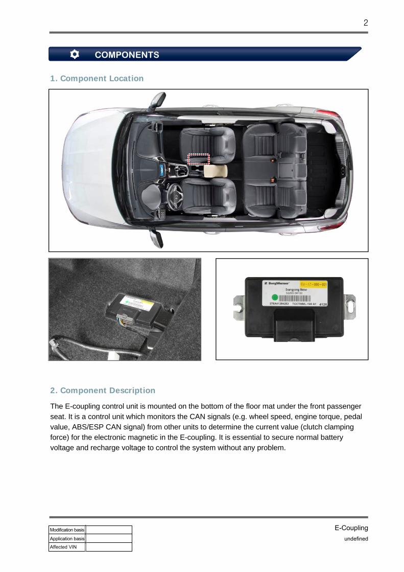
1. Component Location
2. Component Description
The E-coupling control unit is mounted on the bottom of the floor mat under the front passenger seat. It is a control unit which monitors the CAN signals (e.g. wheel speed, engine torque, pedal value, ABS/ESP CAN signal) from other units to determine the current value (clutch clamping force) for the electronic magnetic in the E-coupling. It is essential to secure normal battery voltage and recharge voltage to control the system without any problem.
20000-00

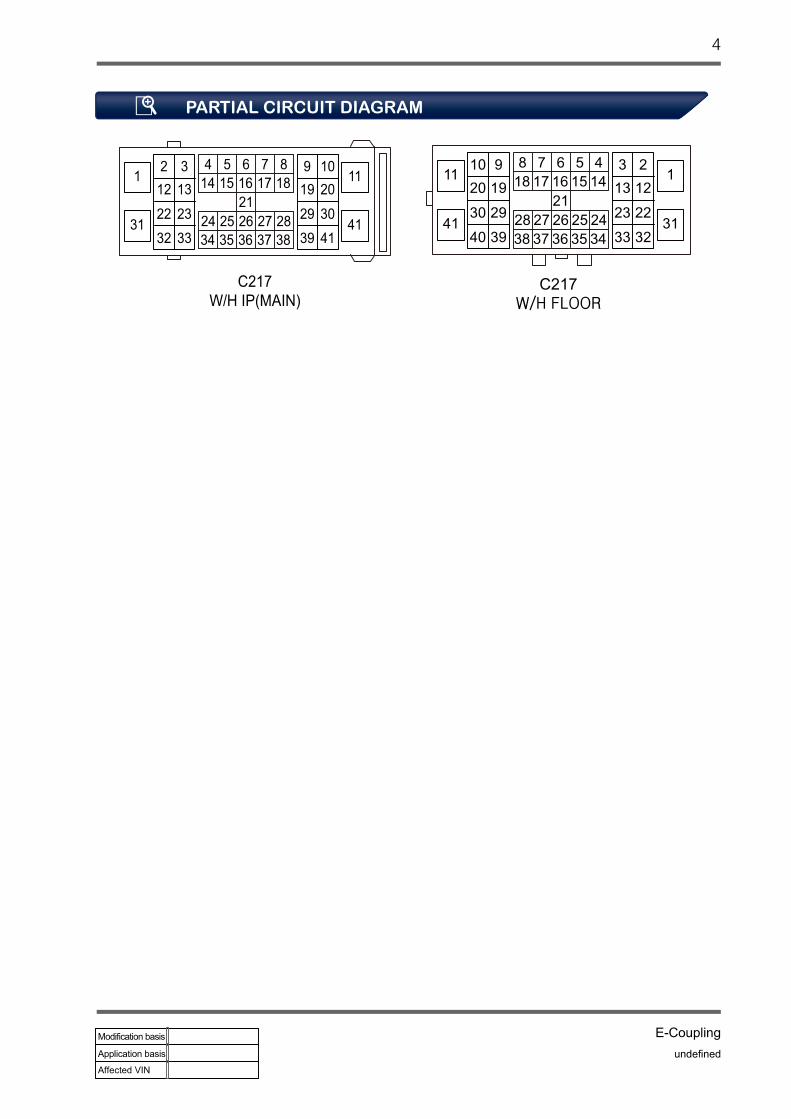
1. Partial Circuit Diagram
2. Connector Appearance
3 0000-00
40000-00

1. Troubleshooting
Connect the DSM to the OBD2 connector.Turn the ignition switch to the "ON" position.Clear any diagnostic trouble code (DTC).
1) 2) 3)
2. Sensor Output
Connect the DSM to the OBD2 connector.Turn the ignition switch to the "ON" position.Check the item "System Voltage" on the diagnostic device.
1) 2) 3)
5 0000-00

2. Check Power Wire
Turn the ignition switch to the "OFF" position.Disconnect the E-coupling unit connector.Turn the ignition switch to the "ON" position.Measure the voltage between the power wire terminal No. 13 of the E-coupling unit wiring connector and the body ground.
1)
2) 3)
4)
Measuring voltage
Tester connection (to wiring) Specification
Terminal No. 13 ↔ BodyBattery voltage
(From min. 9 V to max. 16 V)
Check the battery itself and charging condition, and repair as necessary.
1. Check Charging System
Start the engine.Get the vehicle air conditioner, head lamp and other electrical load to work.Measure the voltages on the alternator terminal B and the battery.
1) 2)
3)
Measuring voltage
Tester connection Specification
Alternator terminal B ↔ Battery (-) Battery voltage(From min. 9 V to max. 16 V)Battery (+) ↔ Battery (-)
Check the power wire for open/short circuit and repair as necessary.
60000-00

3. Check Ground Wire
Turn the ignition switch to the "OFF" position.Disconnect the E-coupling unit connector.Measure the resistance between the ground wire terminal No. 12 of the E-coupling unit wiring connector and body ground.
1) 2) 3)
Measuring resistance
Tester connection (to wiring) Specification
Terminal No. 12 ↔ Body Approx. 0 Ω
Check the ground wire for open circuit and repair as necessary.
4. Final Service Check-up
Perform the inspection procedures again after replacing the E-coupling unit.
This is to check the serviced item again for the last time after the service is completed. Erase DTC(s) again on the diagnostic device.Test drive the vehicle and check the vehicle has recovered its normal condition.
- - -
Service completed (System normal)
7 0000-00

The E-coupling control unit monitors the 4WD LOCK switch and sets a diagnostic trouble code (DTC) if it is defective.
DTC Detection condition Symptom
P1739 4WD LOCK switch stays stuck for more than 30 sec.
Fixed to AWD auto mode
1 0000-00

1. Component Location
2. Component Description
The 4WD LOCK switch is integrated to the lower main switch.Pressing the 4WD LOCK switch activates the 4WD LOCK mode and illuminates the 4WD LOCK indicator lamp on the instrument cluster. In 4WD LOCK mode, the 4WD LOCK control works in the same way as the AUTO mode, but the more driving force is sent to the rear wheels than in AUTO mode.
20000-00

1. Partial Circuit Diagram
2. Connector Appearance
3 0000-00

40000-00

1. Fault Diagnosis
Connect the DSM to the OBD2 connector.Turn the ignition switch to the "ON" position.Clear any diagnostic trouble code (DTC).
1) 2) 3)
If the DTC occurs persistently, refer to the procedure described in the section "Check method".
5 0000-00

2. Check Signal Wire Voltage
Turn the ignition switch to the "OFF" position.Disconnect the lower main switch connector.Measure the voltage between the No. 19 signal wire terminal of the connector to the lower main switch wiring and the body ground.
1)
2)
3))
Measuring voltage
Tester connection (to wiring) Specification
Terminal No. 19 ↔ Body Approx. 11.15 V
Replace the lower main switch.
1. Checking Component
Turn the ignition switch to the "OFF" position.Disconnect the lower main switch connector.Measure the resistance between the terminals No. 19 and 13 of the connector to the lower main switch unit.
1)
2)
3)
If the voltage reading is 0 V, check the signal wire for short circuit to ground or open circuit and repair as necessary.
Measuring resistance
Tester connection (component side) Specification
Terminal No. 19 ↔ Terminal No. 13During operation (depressed): approx. 0 Ω
During non-operation: infinite Ω
60000-00

3. Final Service Check-up
Perform the inspection procedures again after replacing the E-coupling unit.
This is to check the serviced item again for the last time after the service is completed.Erase DTC(s) again on the diagnostic device.Test drive the vehicle and check the vehicle has recovered its normal condition.
- - -
Service completed (System normal)
7 0000-00