00 355917 i-command users guide 3.5-inch - … network “buss” voltage falls below 12.5 volts,...
TRANSCRIPT


IMPORTANT: This User’s Guide outlines the functionality and usage of the I-Command™ Integrated Perfor-mance System. Before using the I-Command Digital gauge, first read and understand ALL of the suppliedproduct literature, as well as the boat’s user’s guide and outboard’s operator’s guide. This User’s Guideshould be stored onboard for reference.
The photographs, illustrations, and display screens used in this Guide might not depict actual models, fig-ures, data fields, equipment, or software versions, but are intended as representative views for referenceonly. The continuing accuracy of this Guide cannot be guaranteed.
† NMEA 2000 is a registered trademark of the National Marine Electronics Association or its subsidiaries.
The following trademarks are the property of Bombardier Recreational Products Inc. or its affiliates.
BRP US Inc. / Outboard Engines Division After Sales Support P.O. Box 597 Sturtevant, WI 53177
Evinrude ® E-TEC ®
I-Command ™
Johnson ®
ICON ™ Electronic Remote Control SystemS.A.F.E. ™ (Speed Adjusting Failsafe Electronics)
Printed in the United States.© 2010 BRP US Inc. All rights reserved.TM, ® Trademarks and registered trademarks of Bombardier Recreational Products Inc. or its affiliates.

About This GuideIMPORTANT: Read this User’s Guide carefullybefore using the I-Command Digital gauge. ThisUser’s Guide should be kept onboard at all timesduring operation.
Need Assistance?For any questions regarding the boat or outboardoperation, please refer to the boat’s user’s guide, oroutboard’s operator’s guide for support information.
For questions or problems regarding the I-Com-mand Digital gauge, contact your dealer.
Dealers with questions should contact BRP Partsand Accessories Technical Help.
WARNINGFor your safety and the safety of others, follow allsafety warnings and recommendations suppliedwith the boat and outboard. Do not disregard any ofthe safety precautions and instructions.
IMPORTANT: This guide was written for 3.5 inchI-Command Digital gauges with softwareversion 2.1.0. Gauges with other software versionsmay have features not documented in this guide. Toview the software version, refer to “System Informa-tion” on page 100.
1. I-Command Digital gauge software version information
MENU
DOWN
UP
EXIT
PAGES
ENTER
System Info
LMF-400Version 2.1.0Build RZ489
1

Table of ContentsInstallation
Description . . . . . . . . . . . . . . . . . . . . . . . . . . . . . . . 4Instruments . . . . . . . . . . . . . . . . . . . . . . . . . . . . . . 5Network Specifications . . . . . . . . . . . . . . . . . . . . . 8Network Setup . . . . . . . . . . . . . . . . . . . . . . . . . . . . 13
Setup and OperationPower Up . . . . . . . . . . . . . . . . . . . . . . . . . . . . . . . . 16Boat Setup . . . . . . . . . . . . . . . . . . . . . . . . . . . . . . . 17Engine Data . . . . . . . . . . . . . . . . . . . . . . . . . . . . . . 21Information Displays . . . . . . . . . . . . . . . . . . . . . . . 22Screen Settings . . . . . . . . . . . . . . . . . . . . . . . . . . . 24Change Units . . . . . . . . . . . . . . . . . . . . . . . . . . . . . 28
Customizing DisplaysFuel Manager . . . . . . . . . . . . . . . . . . . . . . . . . . . . . 32Add Page . . . . . . . . . . . . . . . . . . . . . . . . . . . . . . . . 34Customizing Displays . . . . . . . . . . . . . . . . . . . . . . 40Lock Pages . . . . . . . . . . . . . . . . . . . . . . . . . . . . . . 44Accessing a Locked Page . . . . . . . . . . . . . . . . . . . 46Removing Pages . . . . . . . . . . . . . . . . . . . . . . . . . . 48Page Scrolling . . . . . . . . . . . . . . . . . . . . . . . . . . . . 50Pop-Ups . . . . . . . . . . . . . . . . . . . . . . . . . . . . . . . . . 52
Advanced OperationConfigure Fluid Level Sensor . . . . . . . . . . . . . . . . . 60Fuel or Fluid Level Sensor Calibration . . . . . . . . . . 63Fuel Management . . . . . . . . . . . . . . . . . . . . . . . . . 66Configure Sensors . . . . . . . . . . . . . . . . . . . . . . . . . 72Change Ranges . . . . . . . . . . . . . . . . . . . . . . . . . . . 76Winterize . . . . . . . . . . . . . . . . . . . . . . . . . . . . . . . . 78Audio Settings . . . . . . . . . . . . . . . . . . . . . . . . . . . . 81Reset Values . . . . . . . . . . . . . . . . . . . . . . . . . . . . . 82Sonar Alarms . . . . . . . . . . . . . . . . . . . . . . . . . . . . . 84
TroubleshootingTroubleshooting Steps . . . . . . . . . . . . . . . . . . . . . . 88Engine Warnings . . . . . . . . . . . . . . . . . . . . . . . . . . 89Evinrude E-TEC Engine Warnings . . . . . . . . . . . . . 90Network Troubleshooting Chart . . . . . . . . . . . . . . . 92
ReferenceAbbreviation Tables . . . . . . . . . . . . . . . . . . . . . . . . 96Abreviations Key . . . . . . . . . . . . . . . . . . . . . . . . . . 98System Information . . . . . . . . . . . . . . . . . . . . . . . . 100
Product WarrantyWarranty Statement . . . . . . . . . . . . . . . . . . . . . . . . 102
1

2

Installation
3

DescriptionThe I-Command™ Digital Integrated Performance System uses “plug and play” networking technologybased on NMEA 2000† data communications standards (National Marine Electronics Association). Thesestandards provide communications through a serial data network utilizing a Controller Area Network (CAN)integrated circuit (IC). This network operates at 250 kb/second and allows multiple electronic devices to beconnected together on a common channel for easy information sharing. Multiple digital displays can be usedto monitor and broadcast equipment and engine data.
MENU
DOWN
UP EXIT
PAGES
ENTER
0 70
10 60
20 50
30 40
x 100RPM
4257ENT PWR
MENU EXITDenver
DallasPasoPaso
HoustonJacksonville
Memphis
Indianapolis
Chicago
Toronto
Quebec
New York
Winnipeg
Canada
United States
N 42°21,770’ W 87°49.7 15’ 2000 mi
4

InstrumentsRefer to the current I-Command Digital Network Guide for additional information and complete I-Commandnetwork installation instructions.
Spacing of InstrumentsThe minimum distances between instruments on a panel should be as follows:
•3 13/16 (112 mm) center to center for 3 1/2 in. instruments•3 1/4 in. (95.5 mm) center to center for 3 1/2 in. instruments to 2 in. instruments•2 5/8 in. (77 mm) center to center for 2 in. instruments
Panel ThicknessInstruments can be mounted in panels up to 1 in. thick.
Hole SizesIMPORTANT: Check space behind panel to be sure adequate clearance for instruments exists before drillingpanel.
3 1/2 in. Multifunction Gauge
Cut 3 3/8 in. (99 mm) diameter hole in panel for 3 1/2 in. instruments.
Fastening to PanelInsert instrument into panel hole. Install bracket and tighten nuts finger tight.
5

Gauge Dimensions
3.34 in.(85 mm)
2.20 in.(56 mm)
2.87 in.(72.9 mm)
0.71 in.(18 mm)
3.81 in.(96.9 mm)
1.95 in.(49.5 mm)
6

Warning HornConnect the yellow wire from the instrument to the black wire of the warn-ing horn. Connect the blue wire from the instrument to the red wire of thewarning horn. Each instrument should be installed with a warning horn.Mount each warning horn in a protected area and so horn is audible foroperator.
Navigation Lights (Optional)Connecting the light wiring for the I-Command instrument to the boat’snavigation lights will provide instrument lighting if the instrument backlightsetting is set to lowest setting and the boat’s navigation lights are turnedON.
If desired, connect the white wire from the instrument to the switched posi-tive (B+) of the boat’s navigation lights and the black wire from the instru-ment to ground (GND).
Single Engine Power Supply HarnessConnect the red wire of the power supply harness to the purple switchedB+ accessory wire of the ignition and trim/tilt wire harness. Connect theblack wire of the power harness to the black ground wire of the ignition andtrim/tilt harness.
Warning Horn
7

Multiple Engine Power Supply HarnessConnect the purple wire(s) of the power supply harness to the purple switched B+ accessory wire of the igni-tion and trim/tilt wire harness(es). Connect the black wire of the power harness to a black ground wire of theignition and trim/tilt harness. (Optional: connect the red wire of the power harness to a switched B+ powersupply of the boat.)
Network SpecificationsNetwork Buss LengthThe maximum network buss length must not exceed 100 meters (328 ft.). Measure the distance from thet-connectors to the last device at each end of the network. Device cable lengths at the ends of the networkmust be included in the total network buss length calculation.
DevicesInstall devices in any order. Install temperature, pressure and fluid level sensors, one device at a time. Con-figure the device, see “Advanced Operation” on page 59. If the device data does not display on a defaultpage, add a page, see “Add Page” on page 34. Repeat this process for each device added to the network.
Device Cable Lengths•Must not exceed 6 meters (19 ft.) for single device cable lengths•Must not exceed 78 meters (256 ft.) for total device cable lengths
Maximum Number of DevicesA maximum of 50 devices can be attached to a network.
8

IMPORTANT: There should be no “open” or unused network device connectors. Remove unused networkdevice connectors.
Load EquivalencyThe Engine Management Module (EMM) on Evinrude E-TEC outboards has a load equivalency number of1. Less than 50 mA of the network’s (CAN) power is used by the EMM.
Network Specification Diagram
G P S R E C E I V E R
MENU
DOWN
UP EXIT
PAGES
ENTER
0 70
10 60
20 50
30 40
x 100RPM
4257
NMEA 2000 Devices
Power supply &Groundconnection
6M (19 ft.) 6M (19 ft.)
100M (328 ft.) Maximum Network Buss Length
TerminatorTerminator
Open NetworkConnector REMOVE
Device cables
9

Device Net-style ConnectorsI-Command and NMEA 2000 networks use DeviceNet Micro-C type con-nectors. These connectors use 12 mm threaded locking rings and arewaterproof when assembled properly. All DeviceNet Micro-C connectorsare compatible with I-Command network connectors.
Connectors with slightly different appearances supplied with I-Commandor NMEA 2000 devices should NOT affect network operation. Alwayscheck pin and socket and locking ring configurations when installing con-nectors on a network.
Use the I-Command Product Selection Guide, P/N 764677, or a currentAccessories Parts Catalog (2008 or newer) to look up part numbers forI-Command network connectors. See your dealer.
Connector Installation Connectors have two configurations – Male (pins) and Female (sockets).Lubricate all connector gaskets with Electrical Grease before assembly.
Connectors should assemble easily. Do not force connectors or lockingrings together.
If connectors do not match, an adapter cable may be available. See yourdealer.
10
I-Command Network Connectors (DeviceNet-style Connectors)
DeviceNet Micro-C connectors offered by other suppliers.

Terminating ResistorsTwo terminating resistors are required for accurate network transmissions.Networks must be assembled with one terminator installed at each end ofthe I-Command network. See “Network Specification Diagram” on page 9.
T-connectors and Buss CablesT-connectors provide each device access to the network. Single t-connec-tors have two buss connectors and one device connector. Networkdevices must be connected to the DEVICE connector of the t-connector.
T-connectors can be installed at the end of a network. Connect a networkbuss cable to one side and a terminator into the other.
Multiple t-connectors can be installed in the middle of a network. Networkbuss cables can be used to connect t-connectors or multiple t-connectors.See the “Network Specification Diagram” on page 9.
1. Female terminating resistor (sockets)2. Male terminating resistor (pins)
1. Device connector2. Buss connector
.
1 2D
EVIC
E
BUSS
1
2 2
11

Mounting ConnectorsMount t-connectors to flat mounting surfaces. Use washers or spacers behind the t-connector as needed.Check t-connector alignment. Incorrect mounting can damage the t-connectors resulting in broken wiringconnections. T-connectors should be mounted with the DEVICE connector facing down to prevent waterintrusion. Tighten screws by hand to prevent damage. Groups of t-connectors can be stacked for mountingin larger network installations.
INCORRECT INSTALLATIONCORRECT INSTALLATION
Flat mounting surface
Bend in connectors
Flat mounting surface
Spacer
No spacer
Screws
Screws
Screws
12

Network SetupIMPORTANT: Set “ENGINE OPTIONS” on EvinrudeE-TEC outboards before power is applied to theI-Command network.
Engine OptionsDealers must use Evinrude Diagnostics software to set “ENGINE OPTIONS”. Blank displays, or warning messages appear if engine options are not set. See your dealer to set the following “ENGINE OPTIONS”:
•Set multi engine identity (engine count and engine position)•Calibrate trim sensor•Activate water pressure transducer (if equipped with water pressure transducer, P/N 5008300)
Evinrude Diagnostics software, set engine options
13

Installation Notes
14

Setup and Operation
15

Power UpThe displays and settings for this digital gauge are controlled by a five but-ton keypad. The buttons are:
• UP and DOWN — Use to scroll through and choose menu items• MENU — Use to open basic menu• PAGES / ENTER — Use to scroll forward through pages, and to select
menu items• EXIT— Use to scroll backward through pages, close menus, and to
return to a previous page
IMPORTANT: Make sure boat batteries are fully charged before begin-ning set up procedures. Low voltage on I-Command system can affect net-work performance. Always monitor network buss voltage during set up orwhen configuring network devices. See “Viewing Pass Code” on page 44.If network “buss” voltage falls below 12.5 volts, start the engine or connecta battery charger to the battery.
Turn the ignition key to the ON position. Starting the engine is not required.
1. The Evinrude E-TEC welcome screen will appear.If the gauge then displays a data page, boat setup has been completed. Go to “Information Displays” on page 22.
2. If the gauge then displays the Boat Setup screen, boat setup must be completed before the gauge can be used. Go to “Boat Setup” on page 17.
16
MENU
DOWN
UP
EXIT
PAGES
ENTER
MENU
DOWN
UP EXIT
PAGES
ENTER
Setup Menu�
Boat Setup
�
1
2

Boat Setup
Engine Set Up When the I-Command Digital gauge powers up for the first time, thescreen will show the Boat Setup menu.
Boat Setup must be complete before proceeding.
1. Press ENTER.
2. Press the UP button to set the number of engines installed on the boat. I-Command gauges support up to eight engines.Press ENTER when finished.
Continue Boat Setup with “Fuel Tank Set Up” on page 18.
MENU
DOWNUP EXIT
PAGES
ENTER
Setup Menu�
Boat Setup
�
MENU
DOWN
UP EXIT
PAGES
ENTER
Setup Menu
Press ENTERwhen finished
Num. Engines:
2
1
2
17

Fuel Tank Set Up 1. Use the UP or DOWN buttons to set the number of fuel tanks. I-Command gauges support up to five fuel
tanks. Press ENTER to save selection.
2. Use the UP or DOWN buttons to select measurement units. Press ENTER to save selection.
3. Use the UP or DOWN buttons to set Vessel Fuel Capacity. This is the combined total capacity of all fuel tanks on the boat. Press ENTER when finished. Press the EXIT button to return to the tachometer.
Note: Fuel level senders used in some countries cause the gauge to read FULL when the tank is actuallyEMPTY. Calibrate fluid level sensors, see “Fuel or Fluid Level Sensor Calibration” on page 63, to correctgauge reading.
MENU
DOWN
UP EXIT
PAGES
ENTER
Setup Menu
Press ENTERwhen finished
Num. Fuel Tanks:
0
MENU
DOWN
UP EXITPAGES
ENTER
Units�
US GallonsLiters
�
MENU
DOWN
UP EXIT
PAGES
ENTER
Units
Press ENTERwhen finished
Vessel Fuel Cap:
0 gal
1 2 3
18

Configure Fuel Tank Capacity
The capacity of each tank must be entered.
1. Press MENU. Use the UP or DOWN buttons to select SYSTEM SETUP.Press ENTER.
2. Use the UP or DOWN buttons to select BUS DEVICES.Press ENTER.The gauge will search for devices.
3. Use the UP or DOWN buttons to select the fuel tank to configure.Press ENTER.
MENU
DOWN
UP
EXIT
PAGES
ENTER
�
CustomizePagesScreen
Audio SetupSystem Setup
�
1MENU
DOWNUP
EXIT
PAGES
ENTER
�
Eng WarningsChange UnitsBus DevicesSleep Mode
Sonar AlarmsEng/Tank Cfg
�
MENU
DOWN
UP
EXIT
PAGES
ENTER
�
GPS ModuleOutside TempFuel Tank (P)Fuel Tank (S)Water Press
Oil Level
�
2 3
19

4. Use the UP or DOWN buttons to select RECONFIGURE. Press ENTER.
5. Use the UP or DOWN buttons to select FUEL. Press ENTER.
6. Use the UP or DOWN buttons to select the fuel tank to be configured.Press MENU.
7.Use the UP or DOWN buttons to set the fuel tank capacity. Press ENTER when finished.
Repeat steps 1 through 7 to configure each fuel tank.
For single fuel tank boats, Boat Setup is complete. Go to “Information Dis-plays” on page 22. For multi-engine boats, go to “Engine Data” onpage 21.
MENU
DOWN
UP
EXIT
PAGES
ENTER
�
OilBlack Water
FuelFresh WaterWaste Water
Livewell
�
MENU
DOWN
UP EXITPAGES
ENTER
�
PortCenterStbd
�
5 6
20
MENU
DOWN
UP EXIT
PAGES
ENTER
Press ENTERwhen finished
Setting Tank Size
0.1 gal
7
MENU
DOWN
UP
EXIT
PAGES
ENTER
�
Level WrngUnCofigureReConfigure
CalibrateReset Cal
�
4

Engine DataThe I-Command system monitors up to eight engines. The ENGINE DATA option assigns each I-Commandgauge to monitor a specific engine. Note: This option displays only when two or more engines are connected to the network.
1. Press MENU. Use the UP or DOWN buttons to select SYSTEM SETUP. Press ENTER.
2. Use the UP or DOWN buttons to select ENGINE DATA. Press ENTER.
3. Use the UP or DOWN buttons to select engine. Press ENTER.
Repeat this process to assign each gauge to monitor an engine.
MENU
DOWN
UP
EXIT
PAGES
ENTER
�
CustomizePagesScreen
Audio SetupSystem Setup
�
1MENU
DOWNUP EXIT
PAGES
ENTER
�Fuel Setup
Engine DataSpeed RangePress RangesEng WarningsChange Units
�
2MENU
DOWN
UP EXIT
PAGES
ENTER
Engines�
PortCenterStbd
�
3
21

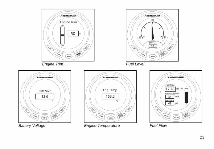
Information DisplaysInformation Displays are known as “Pages.” Pages are an essential part ofthe I-Command Digital gauge. Press the ENTER or EXIT button repeat-edly to scroll through the default pages.
There are seven default pages:
• Tachometer - displays engine rpm• Speedometer - displays ground speed (GND:S)• Fuel Level - displays fuel level percent (FUL:L)• Engine Trim - displays engine trim percent
Note: The trim feature is not available on 90 HP and smaller Evinrude E-TEC models.
• Battery Volts (Batt V) - displays battery voltage• Engine temperature (Eng Temp) - displays engine operating tempera-
ture. in degrees Fahrenheit or Celsius. See “Change Units” on page 28 to customize this display.
• Fuel Flow - displays default fuel management information of ground speed, fuel remaining (Fuel Rem), and fuel level. See “Fuel Management Options” on page 68 to customize this display.
The I-Command gauges are ready for operation.
22
MENU
DOWN
UP EXIT
PAGES
ENTER
0 70
10 60
20 50
30 40
x 100RPM
4257
Tachometer
MENU
DOWN
UP EXIT
PAGES
ENTER
0 70
10 60
20 50
30 40
MPHGND:S
34
Speedometer
MENU
DOWN
UP EXIT
PAGES
ENTER
UP
DN
%
Engine Trim
50
Engine Trim
MENU
DOWN
UP EXIT
PAGES
ENTER
E F
1/2
%FUL:L
48
Fuel Level
MENU
DOWN
UP
EXIT
PAGES
ENTER
V
Batt Volt
13.6
MENU
DOWN
UP EXIT
PAGES
ENTER
° F
Eng Temp
153.2
MENU
DOWN
UP EXIT
PAGES
ENTER
F
E
gal / hr
Ground Speedmph
Fuel Remgal
Fuel Flow
12.78
34
48
Battery Voltage Engine Temperature Fuel Flow
23

Screen SettingsChange the screen settings to improve visibility.
1. Press MENU. Use UP or DOWN buttons to select SCREEN. Press ENTER.
Change Contrast2. Use UP or DOWN buttons to select CONTRAST.
Press ENTER.
3. Use UP button to darken or DOWN button to lighten contrast. Press ENTER when finished.
MENU
DOWN
UP
EXIT
PAGES
ENTER
�
CustomizePagesScreen
Audio SetupSystem Setup
�
MENU
DOWN
UP
EXITPAGES
ENTER
�
BacklightContrast
Reverse Video
�
MENU
DOWN
UP
EXIT
PAGES
ENTER
Contrast Adjust
50%
321
24

Backlight SyncTurn Backlight Sync (Blight Sync) ON to synchronize the lighting of all gauges. Turn Blight Sync OFF tomanually adjust the lighting of individual gauges.
4. Use UP or DOWN buttons to select BACKLIGHT. Press ENTER.
5. Use the UP or DOWN buttons to select BLIGHT SYNC. Press ENTER.
6. Use UP or DOWN buttons to select OFF or ON. Press ENTER when finished.
MENU
DOWN
UP
EXIT
PAGES
ENTER
�
BacklightContrast
Rev Video
�
MENU
DOWNUP
EXIT
PAGES
ENTER
Backlight�
Blight SyncAdjust
�
MENU
DOWN
UP
EXIT
PAGES
ENTER
Blight Sync
�
OffOn
�
4 5 6
25

Adjust BacklightAdjust sets brightness of backlighting from 0 to 100%.
7. Use UP or DOWN buttons to select BACKLIGHT. Press ENTER.
8. Use the UP or DOWN buttons to select ADJUST. Press ENTER.
9. Use the UP button to brighten the backlight. Use the DOWN button to dim the backlight.
Press ENTER when finished.
MENU
DOWN
UP
EXIT
PAGES
ENTER
�
BacklightContrast
Rev Video
�
MENU
DOWN
UP
EXITPAGES
ENTER
Backlight�
Blight SyncAdjust
�
MENU
DOWN
UP
EXIT
PAGES
ENTER
�
�80%
Set Backlight
7 8 9
26

Reverse Video10. Use UP or DOWN buttons to select REVERSE VIDEO. Press ENTER.
Press ENTER to toggle the screen from the light background (11) to the dark background (12).
Press EXIT when finished.
MENU
DOWN
UP
EXIT
PAGES
ENTER
�
BacklightContrast
Reverse Video
�
MENU
DOWNUP EXIT
PAGES
ENTER
E F
1/2
%FUL:L
48
MENU
DOWN
UP EXIT
PAGES
ENTER
FUL:L
48
%
1/2
E F
10 11 12
27

Change UnitsThis example will change the water pressure gauge display from imperial units, to metric units. Use this process to change other units available in the units menu (see step 3).
1. Press MENU. Use the UP or DOWN buttons to select SYSTEM SETUP.Press ENTER.
2. Use the UP or DOWN buttons to select CHANGE UNITS.Press ENTER.
MENU
DOWN
UP EXIT
PAGES
ENTER
MPH
WTR:P
GND:S
0 60
0 40
10 30
20
15 4530
psi
MENU
DOWN
UP
EXITPAGES
ENTER
�
CustomizePagesScreen
Audio SetupSystem Setup
�
MENU
DOWN
UP EXIT
PAGES
ENTER
�Fuel Setup
Engine DisplayedSpeed RangePress RangesEng WarningsChange Units
�
1 2
28

3. Use the UP or DOWN buttons to select PRESSURE.
4. Use the UP or DOWN buttons to select desired units.Press ENTER.
5. Gauge will now display selected units.
MENU
DOWN
UP EXIT
PAGES
ENTER
�
Speed/DistTemperature
PressureDepth
GPS CoordVolume
�
MENU
DOWNUP EXIT
PAGES
ENTER
�Imperial/USSI (Metric)�
MENU
DOWN
UP EXIT
PAGES
ENTER
MPH
WTR:P
GND:S
0 4
0 40
10 30
20
1 3
2
bar
3 4 5
29

Setup Notes
30

Customizing Displays
31

Fuel ManagerUse the Fuel Manager to track the following fuel consumption information:
Also see “Fuel Management” on page 66.
This example shows how to select the data to be displayed.
1. Press the ENTER or EXIT button repeatedly to scroll to the Fuel Man-ager page. Note the center data box is Ground Speed.
2. Press MENU. Use the UP or DOWN buttons to select CUSTOMIZE.Press ENTER.
• Throttle Percentage • Fuel Flow• Fuel Economy • Fuel Consumption• Fuel Remaining • Fuel Used• Fuel Range • Trip Fuel Used• Seasonal Fuel
32
MENU
DOWN
UP EXIT
PAGES
ENTER
F
E
gal / hr
Ground Speedmph
Fuel Remgal
Fuel Flow
12.78
34
48
MENU
DOWN
UP
EXIT
PAGES
ENTER
�
CustomizePagesScreen
Audio SetupSystem Setup
�
1
2

3. Use UP or DOWN buttons to select CENTER DATA.Press ENTER.
4. Press UP or DOWN button to select FUEL ECONOMY.Press ENTER.
5. Press EXIT twice to return to fuel manager page.
Fuel Economy (MPG) is now displayed. Other data boxes can be changed similarly.
MENU
DOWN
UP EXIT
PAGES
ENTER
�
Top DataCenter DataBottom Data
�
MENU
DOWNUP EXIT
PAGES
ENTER
�
Fuel FlowFuel EconomyF ConsumptionFuel Remaining
�
MENU
DOWN
UP EXIT
PAGES
ENTER
F
E
gal / hr
Fuel Economympg
Fuel Remgal
Fuel Flow
12.78
3.56
48
3 4 5
33

Add PageUse Add Page to display additional data when temperature, pressure, fluid level, or other sensors are added to the network. See “Devices” on page 8. Also use Add Page to customize user preferences. Pages display in ana-log or digital format using single, dual, or quad displays.
Eight additional pages can be added. They are:
• Trim Tabs - requires sending unit• GPS Position - requires GPS module• Rudder - requires sending unit• Clock - requires GPS module• Fuel Manager (labeled as Fuel Flow, also a default page)• Engine Trim (also a default page)• Engine Diagnostics• Compass - requires GPS module• Synchronizer – displays RPM for two to eight engines, allowing users to
synchronize the engines for smoother performance.
This example adds the Engine Diagnostics page.
1. Press MENU. Use UP or DOWN buttons to select PAGES. Press ENTER.
2. Press ENTER to select ADD PAGE.
34
MENU
DOWN
UP
EXIT
PAGES
ENTER
�
CustomizePagesScreen
Audio SetupSystem Setup
�
MENU
DOWN
UP EXIT
PAGES
ENTER
�
Add PageRemove PagePage ScrollingPopups Setup
�
1
2

3. Use the UP or DOWN buttons to select Diagnostics. Press ENTER.
4. Press ENTER again to confirm.
5. The Engine Diagnostic page will now display.
MENU
DOWN
UP EXIT
PAGES
ENTER
�
Trim TabsGPS Position
RudderClock
Engine TrimDiagnostics
�
MENU
DOWNUP EXIT
PAGES
ENTER
�
Trim TabsGPS Position
RudderClock
Engine TrimDiagnostics
�
Adding Page Press ENTER
to AddDiagnostics
MENU
DOWN
UP EXIT
PAGES
ENTER
Eng Diagnostics
Engine OK
3 4 5
35

Add Analog PageThe following data can be displayed by an analog page:
This example adds a dual analog gauge display. Select single analog or quad analog to display those options.
1. Press MENU. Use UP or DOWN buttons to select PAGES.Press ENTER.
2. Press ENTER to select ADD PAGE.
• Alt Voltage • GPS Speed (speed over ground)
• Atmospheric Pressure • Paddle Wheel Speed (speed over water)
• Battery Voltage • Pitot Speed• Engine Temp • Tachometer• Fluid Level • Temperature• Engine Water Pressure
36
MENU
DOWN
UP
EXIT
PAGES
ENTER
�
CustomizePagesScreen
Audio SetupSystem Setup
�
MENU
DOWN
UP EXIT
PAGES
ENTER
�
Add PageRemove PagePage ScrollingPopups Setup
�
1
2

3. Press UP button to select DUAL ANALOG. Press ENTER.
4. Press ENTER again to confirm.
The Dual Analog gauge will now display.
To change the default data displayed on any single, dual or quad analog gauge, see “Customizing Displays” on page 40.
MENU
DOWNUP EXIT
PAGES
ENTER
�Single AnalogDual AnalogQuad AnalogSingle DigitalDual DigitalQuad Digital
�
MENU
DOWN
UP EXIT
PAGES
ENTER
%
MPH
FUL:L
GND:S
E F
1/2
0 40
10 30
20
3
4
37

Add Digital PageThe following data can be displayed by a digital page:
This example adds a quad digital display. Select single digital or dual digital to display those options.
1. Press MENU. Use UP or DOWN buttons to select PAGES. Press ENTER.
2. Press ENTER to select ADD PAGE.
• Alt Voltage • Fuel Remaining• Atmospheric Pressure • Seasonal Fuel Used• Battery Voltage • GPS Speed (speed over ground)
• Depth • Paddle Wheel Speed (speed over water)
• Engine Temperature • Pitot Speed• Fuel Economy • Tachometer• Fuel Flow • Temperature• Fuel Range • Total Engine Hours• Fuel Consumption • Throttle Percentage• Fuel Used • Engine Water Pressure• Trip Fuel Used • Time
38
MENU
DOWN
UP
EXIT
PAGES
ENTER
�
CustomizePagesScreen
Audio SetupSystem Setup
�
MENU
DOWN
UP EXIT
PAGES
ENTER
�
Add PageRemove PagePage ScrollingPopups Setup
�
1
2

3. Use UP or DOWN buttons to select QUAD DIGITAL. Press ENTER.
4. Press ENTER again to confirm.
The Quad Digital gauge will now display.
To change the default data displayed on any single, dual or quad digital display, see “Customizing Displays” on page 40.
MENU
DOWNUP EXIT
PAGES
ENTER
�Single AnalogDual AnalogQuad AnalogSingle DigitalDual DigitalQuad Digital
�
MENU
DOWN
UP
EXIT
PAGES
ENTER
%
RPM
Throttle Pct
Time
Hrs
Eng Hrs
4
3
39

Customizing Displays
Change Default DisplayWhen adding pages, each single, dual or quad page has a default display. Use the CUSTOMIZE menu tochange default display data on a page.
1. Press ENTER or EXIT button multiple times to scroll to page to customize.Press MENU.
2. Use UP or DOWN buttons to select CUSTOMIZE.Press ENTER.
3. Use UP or DOWN buttons to select GAUGE (if analog), or DATA BOX (if digital).Press ENTER.
MENU
DOWN
UP EXIT
PAGES
ENTER
%
MPH
FUL:L
GND:S
E F
1/2
0 40
10 3020
MENU
DOWN
UP
EXITPAGES
ENTER
�
CustomizePagesScreen
Audio SetupSystem Setup
�
MENU
DOWN
UP EXIT
PAGES
ENTER
�
Top GaugeBottom Gauge
�
321
40

4. Use UP or DOWN buttons to select desired display item.Press ENTER.
5. Press EXIT once to return to Step 3 to change remaining items.Press EXIT multiple times to return to display.Display change will now appear.
MENU
DOWNUP EXIT
PAGES
ENTER
�
Alt VoltageBatt VoltageEngine Temp
Eng Water PressFuel Pressure
�
MENU
DOWN
UP EXIT
PAGES
ENTER
MPH
WTR:P
GND:S
0 30
0 40
10 30
20
10 20
psi
5
4
41

Configure Time Display1. Press MENU.
Use UP or DOWN buttons to select SYSTEM SETUP. Press ENTER.
2. Use UP or DOWN buttons to select TIME CONFIG. Press ENTER.
3. Use UP or DOWN buttons to select: HOUR FORMAT, go to Step 4.SHOW SECONDS, go to Step 5.
Note: The SHOW SECONDS option is NOT available if time is selected as part of a QUAD DIGITALdisplay. See “Add Digital Page” on page 38.
TIME ZONE go to Step 6.
MENU
DOWN
UP
EXIT
PAGES
ENTER
�
CustomizePagesScreen
Audio SetupSystem Setup
�
MENU
DOWN
UP EXITPAGES
ENTER
�
Sonar AlarmsEng/Tank CfgTime Config
Reset ValuesLock PagesNMEA Info
�
MENU
DOWN
UP EXIT
PAGES
ENTER
Time �
Hour FormatShow Seconds
Time Zone
�
1 2 3
42

4. Use UP or DOWN buttons to select 12 or 24 hour display option. Press ENTER.
5. Use UP or DOWN buttons to select YES or NO. Press ENTER.
6. Use UP or DOWN buttons to select Time Zone. Press ENTER.
7. Press EXIT multiple times to return to time display.
MENU
DOWN
UP EXIT
PAGES
ENTER
Show Seconds �
NoYes
�
MENU
DOWNUP EXIT
PAGES
ENTER
�
GMT -3GMT -2GMT -1
GMTGMT +1GMT +2
�
5 6
MENUDOWN
UP EXIT
PAGES
ENTER
pm
Time
13 : 35 : 47
7
MENU
DOWNUP EXIT
PAGES
ENTER
Hour Format �
24 hrs12 hrs
�
4
43

Lock PagesThe Lock Pages feature prevents unauthorized users from changing selected settings.
Viewing Pass CodeIf you have the PASS CODE, skip to step 4.
1. Press MENU. Use UP or DOWN buttons to select SYSTEM SETUP. Press ENTER.
2. Select NMEA INFO and press ENTER.
3. PASS CODE is the last four digits of the SERIAL NUMBER. Also use this page to monitor buss voltage.
For easy reference, write gauge serial number here: ______________
Press EXIT to return to the MENU.
MENU
DOWN
UP
EXIT
PAGES
ENTER
�
CustomizePagesScreen
Audio SetupSystem Setup
�
MENU
DOWN
UP EXITPAGES
ENTER
�
Sonar AlarmsEng/Tank CfgTime Config
Reset ValuesLock PagesNMEA Info
�
MENU
DOWN
UP
EXIT
PAGES
ENTER
NMEA InfoAddress: 10Instance: 0
Serial Number:6 5 4 3 2 1
NMEA Ver: 1.2.0Bus Volt: 12.8
321
44

Select Pages to Lock4. Use the UP or DOWN buttons to select LOCK PAGES.
Press ENTER.
5. Use the UP or DOWN buttons to change the active digit.Use the MENU button to select the next digit.Press ENTER to submit PASS CODE.
6. Use the UP or DOWN buttons to scroll through the list. Press the MENU button to view the next list.
Press ENTER to select page(s) to be locked. An "x" will appear in the box when a page is selected.
Press EXIT when selection is complete.
MENU
DOWN
UP EXIT
PAGES
ENTER
�
Sonar AlarmsEng/Tank CfgTime Config
Reset ValuesLock PagesNMEA Info
�
MENU
DOWNUP EXIT
PAGES
ENTER
�
Eng/Tank CfgTime Config
Reset ValuesLock PagesNMEA InfoSystem Info
�
Enter Pass-Code
0 0 0 0
MENU
DOWN
UP EXIT
PAGES
ENTER
�
Eng/Tank CfgTime Config
Reset ValuesLock PagesNMEA InfoSystem Info
�
Locked Pages
Customize Pages x Fuel Setup Eng/Tank SetupMENU key for more
654
45

Accessing a Locked PageA locked page requires pass code entry to access and make changes to the locked page. FUEL SETUP is locked in this example.
1. Press MENU. Use UP or DOWN buttons to select SYSTEM SETUP.
2. Select desired page and press ENTER.
3. Enter the gauge PASS CODE. Use the UP or DOWN buttons to change the active digit.Use the MENU button to select the next digit.
Press ENTER to submit PASS CODE.
MENU
DOWN
UP
EXIT
PAGES
ENTER
�
CustomizePagesScreen
Audio SetupSystem Setup
�
MENU
DOWN
UP EXITPAGES
ENTER
�
Fuel SetupSpeed RangePress RangesEng WarningsChange UnitsBus Devices
�
MENU
DOWN
UP EXIT
PAGES
ENTER
�
Fuel SetupSpeed RangePress RangesEng WarningsChange UnitsBus Devices
�
Enter Pass-Code
0 0 0 0
1 2 3
46

4. An incorrect entry will result in an INVALID CODE message. Press ENTER to start over.
5. Correct entry of pass code allows access to page.Use UP or DOWN buttons to select items and make changes.
6. When finished, press ENTER to return to gauge display.
MENU
DOWN
UP EXIT
PAGES
ENTER
�
Fuel SetupSpeed RangePress RangesEng WarningsChange UnitsBus Devices
�
Pass-Code
Invalid Code
MENU
DOWNUP EXIT
PAGES
ENTER
�
Refill TankPartial Fill
Eco Speed SrcFuel Rem SrcRst Trip FuelRst Seasonal
�
MENU
DOWN
UP EXIT
PAGES
ENTER
E F
1/2
%FUL:L
100
654
47

Removing Pages1. Press the ENTER or EXIT button to scroll to the page to be removed.
Press MENU.
2. Use UP or DOWN buttons to select PAGES. Press ENTER.
48
MENU
DOWN
UP EXIT
PAGES
ENTER
WTR: T
ALR:VBATT:V
WTR:P
VoltsVolts
°F psi
20 70
10 35
0 0
20 70
10 35
0 0
x10
MENU
DOWN
UP
EXIT
PAGES
ENTER
�
CustomizePagesScreen
Audio SetupSystem Setup
�
1
2

3. Use UP or DOWN buttons to select REMOVE PAGE. Press ENTER.
4. A confirmation message will appear. Press ENTER to remove page.
The display will return to the next page.
MENU
DOWNUP EXIT
PAGES
ENTER
�
Add PageRemove PagePage ScrollingPopups Setup
�
MENU
DOWN
UP EXIT
PAGES
ENTER
Removing Page
Press ENTER to Remove current Page
4
3
49

Page ScrollingPages can be viewed automatically or by manual scrolling.
Manual
To scroll through pages manually, use the ENTER and EXIT buttons to view pages.
Automatic
To scroll through pages automatically, a viewing interval must be selected.
1. Press MENU. Use the UP or DOWN buttons to select PAGES. Press ENTER.
2. Use the UP or DOWN buttons, select PAGE SCROLLING. Press ENTER.
50
MENU
DOWN
UP
EXIT
PAGES
ENTER
�
CustomizePagesScreen
Audio SetupSystem Setup
�
MENU
DOWN
UP EXIT
PAGES
ENTER
�
Add PageRemove PagePage ScrollingPopups Setup
�
2
1

3. Use the UP or DOWN buttons to select SET TIME. Press ENTER.
4. Use the UP or DOWN buttons to set time.
Select an interval from one to sixty seconds.
Press ENTER to set automatic scrolling interval.
Note: To turn off automatic page scrolling, repeat the first two steps. When the Page Scrolling menu appears, select OFF. Then press ENTER.
MENU
DOWNUP EXIT
PAGES
ENTER
Page Scrolling
�
OffSet Time
�
MENU
DOWN
UP EXIT
PAGES
ENTER
�
Add PageRemove PagePage ScrollingPopups Setup
�
Set Time
5 sec
Press ENTERwhen finished
4
3
51

Pop-UpsThe Pop-Up feature alerts users when changes occur in a monitored cate-gory (RPM, Engine Trim, Trim Tabs or Rudder). Pop-ups appear when auser-specified incremental measurement is met. When an incrementchanges, the main page for the category will pop up on the main displayfor a preset duration. See “Stay-On Time” on page 54 to set pop-up dura-tion.
Setting a Pop-UpThis example illustrates setting the RPM Pop-Up. Engine trim, trim tabs and rudder are set up similarly.
1. Press MENU. Use UP or DOWN buttons to select PAGES.Press ENTER.
2. Use the UP or DOWN button to select POP-UPS SETUP.Press ENTER.
52
MENU
DOWN
UP
EXIT
PAGES
ENTER
�
CustomizePagesScreen
Audio SetupSystem Setup
�
MENU
DOWN
UP EXIT
PAGES
ENTER
�
Add PageRemove PagePage ScrollingPop-ups Setup
�
1
2

3. Use the UP or DOWN button to select RPM.Press ENTER.
4. Use the UP or DOWN button to select:
• OFF to turn off the pop-up, or • SET THRESHOLD to activate the pop-up.
Press ENTER.
5. The threshold for RPM is 50 to 3,000 RPM. Use the UP or DOWN buttons to set the desired value to acti-vate the pop-up.
Press ENTER when finished.
MENU
DOWN
UP EXIT
PAGES
ENTER
�
RPMEngine Trim
Trim TabsRudder
Stay On Time
�
MENU
DOWNUP EXIT
PAGES
ENTER
RPM
�
OffSet Threshold
�
MENU
DOWN
UP EXIT
PAGES
ENTER
�
Add PageRemove PagePage ScrollingPopups Setup
�
Set Threshold
100 rpm
Press ENTERwhen finished
3 4 5
53

Stay-On TimeUse the Stay-on Time feature to adjust the duration of time a Pop-Up win-dow remains visible. See “Setting a Pop-Up” on page 52.
1. Press MENU. Use UP or DOWN buttons to select PAGES.Press ENTER.
2. Use the UP or DOWN button to select POPUPS SETUP.Press ENTER.
54
MENU
DOWN
UP
EXIT
PAGES
ENTER
�
CustomizePagesScreen
Audio SetupSystem Setup
�
MENU
DOWN
UP EXIT
PAGES
ENTER
�
Add PageRemove PagePage ScrollingPop-ups Setup
�
2
1
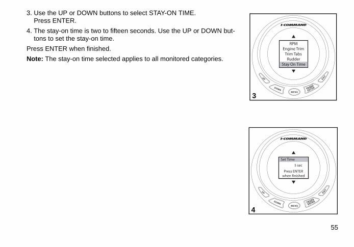
3. Use the UP or DOWN buttons to select STAY-ON TIME. Press ENTER.
4. The stay-on time is two to fifteen seconds. Use the UP or DOWN but-tons to set the stay-on time.
Press ENTER when finished.
Note: The stay-on time selected applies to all monitored categories.
MENU
DOWNUP EXIT
PAGES
ENTER
�
RPMEngine Trim
Trim TabsRudder
Stay On Time
�
3
MENU
DOWN
UP EXIT
PAGES
ENTER
�
Add PageRemove PagePage ScrollingPopups Setup
�
Set Time
5 sec
Press ENTERwhen finished
4
55

Sleep ModeSleep mode allows the I-Command gauge to enter a power-save status tokeep from overdrawing the boat power source.
Note: The Sleep Mode default setting is ON.
1. Press MENU. Use the Up or DOWN buttons to select SYSTEM SETUP.Press ENTER.
2. Use the UP or DOWN button to select SLEEP.Press ENTER.
56
MENU
DOWN
UP
EXIT
PAGES
ENTER
�
CustomizePagesScreen
Audio SetupSystem Setup
�
MENU
DOWN
UP EXIT
PAGES
ENTER
�
Engine WarningsChange UnitsBus DevicesSleep Mode
Sonar AlarmsEng/Tank Cfg
�
1
2

3. Use the UP or DOWN buttons to select ON or OFF.Press ENTER. Gauge will return to last display.
MENU
DOWN
UP EXIT
PAGES
ENTER
9 3
7 5
11 1
8 4
10 2
6
12
MENU
DOWNUP
EXIT
PAGES
ENTER
Sleep Mode�
OffOn
�
3
57

Customizing Notes
58

Advanced Operation
59

Configure Fluid Level SensorThis example configures a Fluid Level Sensor for the second of two fuel tanks. Use this process to set upfluid level sensors for other fluid tanks.
1. Press MENU. Use the UP or DOWN buttons to select SYSTEM SETUP.Press ENTER.
2. Use the UP or DOWN buttons to select BUS DEVICESPress ENTER.
3. The gauge will search for devices.
MENU
DOWN
UP
EXIT
PAGES
ENTER
�
CustomizePagesScreen
Audio SetupSystem Setup
�
MENU
DOWN
UP
EXITPAGES
ENTER
�
Eng WarningsChange UnitsBus DevicesSleep Mode
Sonar AlarmsEng/Tank Cfg
�
MENU
DOWN
UP
EXIT
PAGES
ENTER
�
Eng WarningsChange UnitsBus DevicesSleep Mode
Sonar AlarmsEng/Tank Cfg
�
Message
SearchingBus
Devices...
321
60

4. Use the UP or DOWN buttons to select UNCFG F LEV.Press ENTER.
5. Press ENTER to configure Fluid Level Sensor.
6. Use the UP or DOWN buttons to select FUEL.Press ENTER.
MENU
DOWN
UP
EXIT
PAGES
ENTER
�
Water TempFuel Tank 1UnCfg F LevWater Press
Oil TankStorage Device
�
MENU
DOWNUP
EXIT
PAGES
ENTER
�
Water TempFuel Tank 1UnCfg F LevWater Press
Oil TankStorage Device
�
Configuring
Press ENTERto Configure
Fluid Lev Snsr
MENU
DOWN
UP
EXIT
PAGES
ENTER
�
OilBlack Water
FuelFresh WaterWaste Water
Live Well
�
54 6
61

7. Use the UP or DOWN buttons to select the tank.Press ENTER.
8. The gauge will change the tank setting and return to the BUS DEVICES list.
Proceed to “Fuel or Fluid Level Sensor Calibration” on page 63.
62
MENU
DOWN
UP
EXIT
PAGES
ENTER
Select Tank�
Tank 1Tank 2
�
MENU
DOWN
UP
EXIT
PAGES
ENTER
Select Tank�
Tank 1Tank 2
�
Message
ChangingDevice Settings
7
8

Fuel or Fluid Level Sensor CalibrationFluid level sensors rely on the tank sending unit to calculate remainingfluid level. Fluid level reading is dependent on sending unit accuracy andcapacity entered during setup. A FIVE POINT calibration is the most accu-rate.
• Two-Point calibrates EMPTY and FULL levels.• Three-Point calibrates EMPTY, 50% and FULL levels. • Five-Point calibrates EMPTY, 25%, 50%, 75% and FULL levels.
This example illustrates a 2-Point Calibration. Follow the on-screen prompts if a Three or Five-Point Calibration is desired.
IMPORTANT: The tank should be EMPTY before starting calibration. Afteradding fluid to the tank, allow a few seconds for the sending unit to stabi-lize before pressing ENTER.
1. Press MENU. Use the UP or DOWN buttons to select SYSTEM SETUP.Press ENTER.
2. Use the UP or DOWN buttons to select BUS DEVICESPress ENTER.
WARNINGRunning out of fuel could cause the operator of the boat to havediminished or no control of the vessel, presenting a risk of personalinjury to the operator, passengers, and people who are nearby.
MENU
DOWNUP
EXIT
PAGES
ENTER
�
CustomizePagesScreen
Audio SetupSystem Setup
�
MENU
DOWN
UP
EXIT
PAGES
ENTER
�
Eng WarningsChange UnitsBus DevicesSleep Mode
Sonar AlarmsEng/Tank Cfg
�
2
1
63

3. The gauge will search for devices.
4. Use the UP or DOWN buttons to select the device to be calibrated.Press ENTER.
5. Use the UP or DOWN buttons to select CALIBRATE.Press ENTER.
6. Use the UP or DOWN buttons to select the number of points for the cal-ibration.Press ENTER.
MENU
DOWN
UP
EXIT
PAGES
ENTER
�
Water TempFuel Tank 1Fuel Tank 2Water Press
Oil TankStorage Device
�
MENU
DOWN
UP
EXITPAGES
ENTER
�
Level WrngUnConfigureReConfigure
CalibrateReset Cal
Reset Values
�
54
64
MENU
DOWN
UP
EXIT
PAGES
ENTER
Num of Points�
235
�
6
MENU
DOWN
UP
EXIT
PAGES
ENTER
�
Eng WarningsChange UnitsBus DevicesSleep Mode
Sonar AlarmsEng/Tank Cfg
�
Message
SearchingBus
Devices...
3

7. Select EMPTY LEVEL.Press ENTER.
8. Be sure the tank is EMPTY.Press ENTER.
9. Select FULL LEVEL.Press ENTER.
10. Fill the tank.Allow a few seconds for the sending unit to stabilize.Press ENTER.
MENU
DOWN
UP
EXIT
PAGES
ENTER
�
Empty LevelFull Level
�
Calibrating
Set Tank toEmpty LevelPress ENTER
MENU
DOWNUP
EXIT
PAGES
ENTER
�
Empty LevelFull Level
�
98
MENUDOWN
UP
EXIT
PAGES
ENTER
�
Empty LevelFull Level
�
Calibrating
Set Tank toFull Level
Press ENTER
10
MENU
DOWNUP
EXIT
PAGES
ENTER
�
Empty LevelFull Level
�
7
65

Fuel ManagementFuel Remaining SourceThe I-Command gauge uses Fuel Remaining Source to determine the amount of fuel remaining. The defaultsetting is FLUID LEV SNSR.
1. Press MENU. Use the UP or DOWN buttons to select SYSTEM SETUP. Press ENTER.
2. Use the UP or DOWN buttons to select FUEL SETUP. Press ENTER.
3. Use the UP or DOWN buttons to select FUEL REM SRC. Press ENTER.
MENU
DOWN
UP
EXIT
PAGES
ENTER
�
CustomizePagesScreen
Audio SetupSystem Setup
�
MENU
DOWN
UP EXITPAGES
ENTER
�
Fuel SetupEngine Displayed
Speed RangePress RangesEng WarningsChange Units
�
MENU
DOWN
UP EXIT
PAGES
ENTER
�
Refill TankPartial Fill
Eco Speed SrcFuel Rem SrcRst Trip FuelRst Seasonal
�
321
66
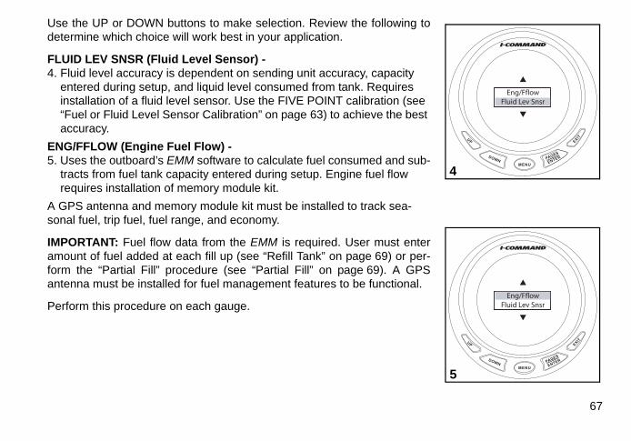
Use the UP or DOWN buttons to make selection. Review the following todetermine which choice will work best in your application.
FLUID LEV SNSR (Fluid Level Sensor) - 4. Fluid level accuracy is dependent on sending unit accuracy, capacity
entered during setup, and liquid level consumed from tank. Requires installation of a fluid level sensor. Use the FIVE POINT calibration (see “Fuel or Fluid Level Sensor Calibration” on page 63) to achieve the best accuracy.
ENG/FFLOW (Engine Fuel Flow) - 5. Uses the outboard’s EMM software to calculate fuel consumed and sub-
tracts from fuel tank capacity entered during setup. Engine fuel flow requires installation of memory module kit.
A GPS antenna and memory module kit must be installed to track sea-sonal fuel, trip fuel, fuel range, and economy.
IMPORTANT: Fuel flow data from the EMM is required. User must enteramount of fuel added at each fill up (see “Refill Tank” on page 69) or per-form the “Partial Fill” procedure (see “Partial Fill” on page 69). A GPSantenna must be installed for fuel management features to be functional.
Perform this procedure on each gauge.
MENU
DOWNUP EXIT
PAGES
ENTER
�
Eng/FflowFluid Lev Snsr
�
MENU
DOWN
UP EXIT
PAGES
ENTER
�
Eng/FflowFluid Lev Snsr
�
5
4
67

Fuel Management OptionsUse the following steps to access fuel management options.
1.Press MENU.Use UP or DOWN buttons to Select SYSTEM SETUP. Press ENTER.
2. Use UP or DOWN buttons to select FUEL SETUP. Press ENTER.
3. Use the UP or DOWN buttons to select REFILL TANK or PARTIAL FILL.Press ENTER.
MENU
DOWN
UP
EXIT
PAGES
ENTER
�
CustomizePagesScreen
Audio SetupSystem Setup
�
MENU
DOWN
UP EXITPAGES
ENTER
�Fuel Setup
Engine DisplayedSpeed RangePress RangesEng WarningsChange Units
�
MENU
DOWN
UP
EXIT
PAGES
ENTER
�
Refill TankPartial Fill
Eco Speed SrcFuel Rem SrcRst Trip FuelRst Seasonal
�
321
68

Refill Tank1. Choose the Refill Tank option to recalibrate the fuel tank level after it has
been filled to full capacity.
Press the ENTER button after fuel tank has been filled.
Note: Only supported when the memory module is used as the fuel remaining source.
Partial Fill2. Choose the Partial Fill option to maintain the accuracy of the level by allowing the operator to input fuel added to the tank.
Use the UP button to enter the quantity of fuel added to the fuel tank.
Use the UP or DOWN button to make adjustments.
Press ENTER when finished.
Note: Only supported when the memory module is used as the fuel remaining source.
MENU
DOWNUP
EXIT
PAGES
ENTER
�
Refill TankPartial Fill
Eco Speed SrcFuel Rem SrcRst Trip FuelRst Seasonal
�
Refill Tank
Press ENTERafter refillingthe fuel tank
MENU
DOWN
UP
EXIT
PAGES
ENTER
�
Refill TankPartial Fill
Eco Speed SrcFuel Rem SrcRst Trip FuelRst Seasonal
�
Adding Fuel
0.00 gal
Press ENTERwhen finished
2
1
69

Economy Speed SourceThe Economy Speed Source option sets the speed measurement source.
Press MENU.Use UP or DOWN buttons to Select SYSTEM SETUP. Press ENTER.
Use UP or DOWN buttons to select FUEL SETUP. Press ENTER.
1. Use the UP or DOWN buttons to select ECO SPEED SRC.Press ENTER.
2. Use UP or DOWN buttons to select:
• Water Speed (Paddle Wheel) works best for low speeds.• Pitot Speed works best for high speeds. • Ground Speed (GPS) works well for both high and low speeds.Press ENTER when finished.
Reset Fuel UsageFuel usage can be tracked for trips and an entire season.
Press MENU.Use UP or DOWN buttons to Select SYSTEM SETUP. Press ENTER.
Use UP or DOWN buttons to select FUEL SETUP. Press ENTER.
70
MENU
DOWN
UP
EXIT
PAGES
ENTER
�
Refill TankPartial Fill
Eco Speed SrcFuel Rem SrcRst Trip FuelRst Seasonal
�
MENU
DOWN
UP
EXIT
PAGES
ENTER
Eco Speed Src�
Water SpeedPitot Speed
Ground Speed
�
2
1

Use the following steps to reset fuel usage.
Reset Trip Fuel1. Use the UP or DOWN buttons to select RESET TRIP FUEL.
Press ENTER to reset the trip fuel total to zero.
Reset Seasonal Fuel2. Use the UP or DOWN buttons to select RESET TRIP FUEL.
Press ENTER to reset the seasonal fuel total to zero.
Note: For multi-engine applications, select the appropriate engine to reset,or select ALL ENGINES to simultaneously reset all engines.
MENU
DOWNUP
EXIT
PAGES
ENTER
�
Refill TankPartial Fill
Eco Speed SrcFuel Rem SrcRst Trip FuelRst Seasonal
�
Rst Trip Fuel
Press ENTERto reset
Trip Fuel
MENU
DOWN
UP
EXIT
PAGES
ENTER
�
Refill TankPartial Fill
Eco Speed SrcFuel Rem SrcRst Trip FuelRst Seasonal
�
Rst Seasonal
Press ENTERto reset
Seasonal Fuel
2
1
71

Configure SensorsFollow these steps to add new unconfigured sensors to the network.
Temperature Sensor1. Press MENU. Use the UP or DOWN buttons to select SYSTEM SETUP.
Press ENTER.
2. Use the UP or DOWN buttons to select BUS DEVICES.Press ENTER.
3. The gauge will search for devices.
MENU
DOWN
UP
EXIT
PAGES
ENTER
�
CustomizePagesScreen
Audio SetupSystem Setup
�
MENU
DOWN
UP
EXITPAGES
ENTER
�
Eng WarningsChange UnitsBus DevicesSleep Mode
Sonar AlarmsEng/Tank Cfg
�
MENU
DOWN
UP
EXIT
PAGES
ENTER
�
Eng WarningsChange UnitsBus DevicesSleep Mode
Sonar AlarmsEng/Tank Cfg
�
Message
SearchingBus
Devices...
321
72

4. Use the UP or DOWN buttons to select UNCFG TEMP.Press ENTER.
5. Press ENTER to configure Temperature Sensor.
6. Use the UP or DOWN buttons to make selection.Press ENTER.
7. The gauge will save the change the to the device and return to the BUS DEVICES list.
Press EXIT three times to return to gauge display.
MENU
DOWN
UP
EXIT
PAGES
ENTER
�
Water TempFuel Tank 1UnCfg F LevWater Press
Oil TankStorage Device
�
Configuring
Press ENTERto ConfigureTemp Sensor
MENU
DOWNUP
EXIT
PAGES
ENTER
�
Water TempOutside TempInside Temp
Engine RoomLive WellBait Well
�
5 6
MENUDOWN
UP
EXIT
PAGES
ENTER
�
Water TempOutside TempInside Temp
Engine RoomLive WellBait Well
�
Message
ChangingDevice Settings
7
MENU
DOWNUP
EXIT
PAGES
ENTER
�
Water TempFuel Tank 1
UnCfg TempWater Press
Oil TankStorage Device
�
4
73

Configure Pressure Sensor1. Press MENU. Use the UP or DOWN buttons to select SYSTEM SETUP.
Press ENTER.
2. Use the UP or DOWN buttons to select BUS DEVICES.Press ENTER.
3. The gauge will search for devices.
MENU
DOWN
UP
EXIT
PAGES
ENTER
�
CustomizePagesScreen
Audio SetupSystem Setup
�
MENU
DOWN
UP
EXITPAGES
ENTER
�
Eng WarningsChange UnitsBus DevicesSleep Mode
Sonar AlarmsEng/Tank Cfg
�
MENU
DOWN
UP
EXIT
PAGES
ENTER
�
Eng WarningsChange UnitsBus DevicesSleep Mode
Sonar AlarmsEng/Tank Cfg
�
Message
SearchingBus
Devices...
321
74

4. Use the UP or DOWN buttons to select UNCFG PRESS.Press ENTER.
5. Press ENTER to configure Pressure Sensor.
6. Use the UP or DOWN buttons to make selection.Press ENTER.
7. The gauge will save the change the to the device and return to the BUS DEVICES list.
Press EXIT three times to return to gauge display.
MENU
DOWN
UP
EXIT
PAGES
ENTER
�
Water TempFuel Tank 1UnCfg F LevWater Press
Oil TankStorage Device
�
Configuring
Press ENTERto ConfigurePress Sensor
MENU
DOWNUP
EXIT
PAGES
ENTER
�
Pitot SpeedWtr Press
�
65
MENUDOWN
UP
EXIT
PAGES
ENTER
�
Fuel PressureOutside TempInside Temp
Engine RoomLive Well
Eng Water Press
�
Message
ChangingDevice Settings
7
MENU
DOWNUP
EXIT
PAGES
ENTER
�
Water TempFuel Tank 1UnCfg PressWater Press
Oil TankStorage Device
�
4
75

Change RangesThis example will change the water pressure gauge to read from 0 – 60 psi, to 0 – 30 psi. Speed ranges andother pressure ranges can be changed in the same manner.
1. Press the ENTER or EXIT buttons repeatedly to scroll to the page to be changed.
2. Press MENU. Use the UP or DOWN buttons to select SYSTEM SETUP.Press ENTER.
3. Use the UP or DOWN buttons to select PRESS RANGES.Press ENTER.
MENU
DOWN
UP EXIT
PAGES
ENTER
MPH
WTR:P
GND:S
0 60
0 40
10 30
20
15 4530
psi
MENU
DOWN
UP
EXITPAGES
ENTER
�
CustomizePagesScreen
Audio SetupSystem Setup
�
MENU
DOWN
UP EXIT
PAGES
ENTER
�
Fuel SetupEngine Displayed
Speed RangePress RangesEng WarningsChange Units
�
321
76

4. Use the UP or DOWN buttons to select WATER PRESS.Press ENTER.
5. Use the UP or DOWN buttons to select desired pressure range.Press ENTER.
6. Gauge will now display selected range.
MENU
DOWN
UP
EXIT
PAGES
ENTER
�
Pitot SpeedWtr Press
�
MENU
DOWNUP EXIT
PAGES
ENTER
�
0-15 psi0-30 psi0-60 psi0-80 psi
0-100 psi
�
MENU
DOWN
UP EXIT
PAGES
ENTER
%
MPH
WTR:P
GND:S
0 30
0 40
10 30
20
10 20
psi
654
77

WinterizeThe 3.5 inch I-Command digital gauge provides a winterize feature for 2008 and newer 115–300 HP V4/V6Evinrude E-TEC outboard models.
The engine must be running to use this option. Refer to the Outboard Operator's Guide for complete storageprocedures and Safety Precautions.
1. Press MENU. Use the UP or DOWN buttons to select SYSTEM SETUP.Press ENTER.
2. Use the UP or DOWN buttons to select BUS DEVICES.Press ENTER.
3. The gauge will search for devices.
MENU
DOWN
UP
EXIT
PAGES
ENTER
�
CustomizePagesScreen
Audio SetupSystem Setup
�
MENU
DOWN
UP
EXITPAGES
ENTER
�
Eng WarningsChange UnitsBus DevicesSleep Mode
Sonar AlarmsEng/Tank Cfg
�
MENU
DOWN
UP
EXIT
PAGES
ENTER
�
Eng WarningsChange UnitsBus DevicesSleep Mode
Sonar AlarmsEng/Tank Cfg
�
Message
SearchingBus
Devices...
321
78

4. Use the UP or DOWN buttons to select engine to winterize. Press ENTER.
5. The gauge will display WINTERIZE menu. Press ENTER.
6. Press ENTER again.
MENU
DOWN
UP
EXIT
PAGES
ENTER
�
Water TempFuel Tank 1
Evinrude PortEvinrude CenterEvinrude StbdStorage Device
�
MENU
DOWNUP
EXIT
PAGES
ENTER
�
Winterize
�
MENU
DOWN
UP
EXIT
PAGES
ENTER
�
Winterize
�
Winterization
Press ENTERto Start
the Process
654
79

7. The gauge will display WINTERIZATION message.
8. When prompted, engage NEUTRAL only button on remote control and advance THROTTLE ONLY to at least 50%.
9. Gauge will display WINTERIZATION IN PROGRESS message.
10. When the winterization cycle is complete the engine will shut off and the gauge will display WINTERIZATION IS COMPLETE message.
Press EXIT to return to BUS DEVICES menu.
Repeat steps 4 through 10 for other engines (two through five enginesonly).
MENU
DOWN
UP
EXIT
PAGES
ENTER
�
Winterize
�
Winterization
Advance Throttleto 50%
MENU
DOWN
UP
EXITPAGES
ENTER
�
Winterize
�
Winterization
Winterizationin Progress
98
80
MENU
DOWN
UP
EXIT
PAGES
ENTER
�
Winterize
�
Winterization
Winterizationis Complete
10
MENU
DOWN
UP
EXIT
PAGES
ENTER
�
Winterize
�
Winterization
Receiving Datato Start
the Process
7

Audio SettingsAudio functions of the I-Command Digital gauge can be turned OFF or ON.
1. Press MENU. Use the UP or DOWN buttons to select AUDIO SETUP. Press ENTER.
2. Use the UP or DOWN buttons to select KEY SOUNDS. Press ENTER.
3. Use the UP or DOWN buttons to select ON or OFF setting. Press ENTER when finished.
MENU
DOWN
UP
EXIT
PAGES
ENTER
�
CustomizePagesScreen
Audio SetupSystem Setup
�
MENU
DOWNUP
EXIT
PAGES
ENTER
�
Key Sounds
�
MENU
DOWN
UP
EXIT
PAGES
ENTER
Key Sounds�
OffOn
�
321
81

Reset ValuesUse RESET VALUES to restore the gauge default settings. Reset Valueswill not clear sensor settings that were previously calibrated or configured.
1. Press MENU. Use UP or DOWN buttons to select SYSTEM SETUP.Press ENTER.
2. Use UP or DOWN buttons to select RESET VALUES. Press ENTER.
82
MENU
DOWN
UP
EXIT
PAGES
ENTER
�
CustomizePagesScreen
Audio SetupSystem Setup
�
MENU
DOWN
UP EXIT
PAGES
ENTER
�Sonar AlarmsEng/Tank CfgTime ConfigReset ValuesLock PagesNMEA Info�
1
2

3. Use UP or DOWN buttons to select PAGES, SETTINGS or ALL. Press ENTER.
•Select PAGES to reset the seven factory default pages. See “Informa-tion Displays” on page 22.•Select SETTINGS to reset Fuel Remaining Source, Fuel EconomySpeed Source, Keypad Sounds, Sleep Mode, Fluid Level Warnings,Sonar Alarms and Boat Set Up.
•Select ALL to reset both.
4. A confirmation message will appear. Press ENTER to continue.
MENUDOWNUP EXIT
PAGES
ENTER
�
PagesSettings
All
�
Sel Option
MENU
DOWN
UP EXIT
PAGES
ENTER
Resetting ValuesPress ENTER
to reset All values
Sel Option
3
4
83

Sonar AlarmsSonar alarms are available to aid in avoiding underwater objects or shal-low operating conditions. A transducer or triducer is required for sonaralarm functionality.
This example will set the shallow sonar alarm.
1. Press MENU. Use UP or DOWN buttons to select SYSTEM SETUP.Press ENTER.
2. Use UP or DOWN buttons to select SONAR ALARMS. Press ENTER.
84
MENU
DOWN
UP
EXIT
PAGES
ENTER
�
CustomizePagesScreen
Audio SetupSystem Setup
�
MENU
DOWN
UP EXIT
PAGES
ENTER
�
Change UnitsBus DevicesSleep Mode
Sonar AlarmsEng/Tank CfgTime Config
�
1
2

3. Use UP or DOWN buttons to select SHALLOW (or DEEP) alarm. Press ENTER.
4. Use UP or DOWN buttons to select SET DEPTH (or OFF).
5. Use UP button to set depth. Use UP or DOWN buttons to make adjustments. Press ENTER to save selection.
To set DEEP alarm, press EXIT one and go to Step 3.
To turn sonar alarms OFF, press EXIT and go to Step 4.
Press EXIT four times, when finished.
MENU
DOWN
UP
EXIT
PAGES
ENTER
Sonar Alarms�
ShallowDeep
�
MENU
DOWNUP
EXIT
PAGES
ENTER
Shallow�
OffSet Depth
�
MENU
DOWN
UP
EXIT
PAGES
ENTER
Shallow�
OffSet Depth
�
Set Depth
4ft
Press ENTERwhen finished
543
85

Advanced Operation Notes
86

Troubleshooting
87
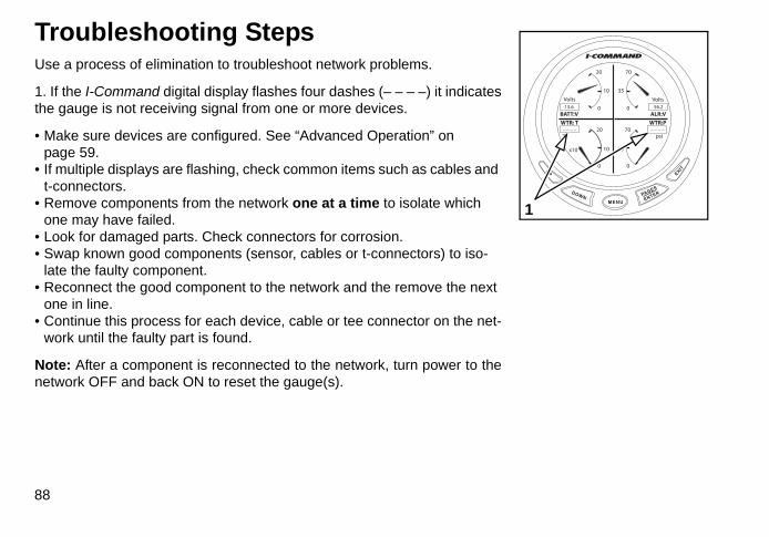
Troubleshooting StepsUse a process of elimination to troubleshoot network problems.
1. If the I-Command digital display flashes four dashes (– – – –) it indicatesthe gauge is not receiving signal from one or more devices.
• Make sure devices are configured. See “Advanced Operation” on page 59.
• If multiple displays are flashing, check common items such as cables and t-connectors.
• Remove components from the network one at a time to isolate which one may have failed.
• Look for damaged parts. Check connectors for corrosion.• Swap known good components (sensor, cables or t-connectors) to iso-
late the faulty component.• Reconnect the good component to the network and the remove the next
one in line.• Continue this process for each device, cable or tee connector on the net-
work until the faulty part is found.
Note: After a component is reconnected to the network, turn power to thenetwork OFF and back ON to reset the gauge(s).
88
MENU
DOWN
UP EXIT
PAGES
ENTER
WTR: T
ALR:VBATT:V
WTR:P
VoltsVolts
°F psi– – – –– – – –
13.6 56.2
20 70
10 35
0 0
20 70
10 35
0 0
x10
1

Engine WarningsI-Command gauges monitor engine conditions and display warnings in the event of a malfunction. Refer tothe outboard Operator’s Guide if engine warnings are displayed.
WARNING MESSAGE DISPLAYED POSSIBLE CAUSE PROCEDURE
Check EngineA “Check Engine” condition is activated when a critical engine condition occurs, or when a service is required.
· A “critical” condition activates S.A.F.E. (RPM reduction) - Seek assistance to return to safe harbor immediately and see your dealer. Continued operation in S.A.F.E. could result in an Engine Shut Down condition. · A minor service issue will NOT activate S.A.F.E. - See your dealer as soon as practical.
Over Temperature Engine or EMM above temperature range. Check cooling water to water intake screens.
Low Oil Level A low oil level has been detected. Fill oil tank.
Low System Voltage A low voltage condition has been detected. See dealer for service.
Throttle Position Sensor A throttle position sensor fault has been detected.
Rev Limit Exceeded The RPM limit has been exceeded. Reduce throttle.
Power Reduction EMM has activated S.A.F.E. See dealer for service immedi-ately.Engine Shutting Down EMM has activated engine shutdown.
Neutral Start Protection Attempt to start engine while in gear. Shift to neutral.
89

Evinrude E-TEC Engine WarningsI-Command gauges monitor engine conditions and display warnings in the event of a malfunction. The fol-lowing table lists warnings that are specific to Evinrude E-TEC models. Refer to the outboard Operator’sGuide if engine warnings are displayed.
WARNING MESSAGE DISPLAYED POSSIBLE CAUSE PROCEDURE
Sensor malfunction see dealer
Throttle position sensor fault detected.
See dealer for service.
Analog 5V supply overload detected.
Knock Sensor circuit fault detected.
Water Pressure Transducer fault detected.
Exhaust pressure circuit fault detected.
Sensor malfunction service soonEngine temperature sensor, Air temperature sensor, Oil pressure circuit or Water pressure circuit fault detected.
Water in Fuel, service soon Water in fuel detected (115–300 HP models).
Low battery voltage see manual Battery voltage below expected range.
RPM reductn activated see dealer
System Voltage below expected range.
See dealer for service immediately.System Voltage above expected range.
Excessive Engine Knock detected(200–300 HP 90° V6 models).
Winterization Mode activated Auto-winterization activated (115–300 HP models). See “Winterize” on page 78.
Overheat RPM reductn activated see manual EMM temperature above expected range.
See engine Operator’s Guide.Engine Over Temp Fault Engine temperature above normal range.
90

WARNING MESSAGE DISPLAYED POSSIBLE CAUSE PROCEDURE
Overheat RPM reductn chk water & manual Engine temperature above range.
See engine Operator’s Guide.Overheat Eng Shutdwn see manual
Engine shutdown, EMM above max temperature.
Engine shutdown, engine above max temperature.
No Oil Shutdwn see manual Engine shutdown, excessive no oil fault.
Seek assistance to return to harbor, see dealer immediately.
No Oil RPM reductn check oil Oil solenoid open circuit.
No Oil RPM reductn see dealer Oil pressure pulses in manifold not detected.
No Oil RPM reductn see dealer Oil system prime failure.
Engine Shutdown see dealer Possible fuel leak.
RPM reductn activated, ICON fault – See ICON Remote Control User’s Guide.
Injector malfunction see dealer Fuel injector open or short circuit detected.
See dealer for service immediately.
Solenoid malfunction see dealer
Starter solenoid circuit open-circuit(115–300 HP models).
Water injection solenoid open circuit(60–65 HP models).
Ignition malfunction see dealer Ignition primary open circuit detected.
Fuel pump malfunction see dealer Fuel pump open circuit detected.
Power valve malfunction see dealer Exhaust valve solenoid open circuit(115–130 HP models).
91

Network Troubleshooting Chart
OBSERVATION POSSIBLE CAUSE PROCEDURE
I-Command gauge screen is dark. Gauge does not turn ON.
I-Command gauge is not connected to the network. Check connection.
Power supply cable 3A fuse is failed. Check fuse, replace as needed.
The tee connector that the gauge is plugged into has failed.
Inspect tee connector for damage.Swap known good tee connector.
The power supply cable is not connected to the Ignition and Trim/Tilt harness. Check connection.
I-Command gauge screen is dark. Gauge does not turn ON.3A fuse repeatedly fails.
Network current draw is exceeding 3A.Check all connections and wiring. Disconnect accessory connections to network. See “Troubleshooting Steps” on page 88.
I-Command instrument display is erratic. Terminators not installed.
Check terminator installation. Check network buss cable and device connec-tions. See “Terminating Resistors” on page 11.
No “Fuel Manager”. Requires memory module and setup of the I-Command display. See “Fuel Management” on page 66.
No “Fuel Economy” display for Fuel Manager.
No signal from NMEA 2000 GPS receiver. See “Fuel Manager” on page 32.
Four dashes “----” displayed on LCD (Engine related functions).
EMM harness is not connected. Check connections at EMM and t-connector.
EMM harness is damaged. Inspect EMM harness for damage. Swap known good EMM harness.
The tee connector that the EMM harness is plugged into has failed.
Inspect tee connector for damage. Swap known good tee connector.
Engine position incorrectly set. Use Evinrude Diagnostics software to check/set outboard position.
92

OBSERVATION POSSIBLE CAUSE PROCEDURE
Invalid Fluid Level message displayed on gauge.
Vessel fuel capacity and fuel tank capac-ity do not match.
The capacity of each fuel tank must be entered during set up. See “Configure Fuel Tank Capacity” on page 19.
Configuration Mismatch Error message displayed on gauge. Occurs when a device is replaced.
Configuration of device does not match Boat Setup. Configure device to match Boat Setup.
Four dashes “----” displayed on LCD (Sensor related functions): No signal from NMEA 2000 device:
Check that the device is installed and con-nected to the network.
Use the “Bus Devices” menu to confirm the device is communicating on the network.
See “Troubleshooting Steps” on page 88.
• No speed display.• No signal from speed transducer or
GPS receiver.
• Speed-Over-Ground (SOG) does not display.
• No signal from GPS receiver.
• Speed-Over-Water (SOW) does not display.
• No signal from speed transducer.
• Water depth does not display. • No signal from depth transducer.
• Temperature does not dis-play.
• No signal from temperature trans-ducer.
• Fluid level (Fuel, Oil or other) does not display.
• No signal from fluid level sensor.See “Configure Fluid Level Sensor” on page 60. See “Fuel or Fluid Level Sensor Cali-bration” on page 63.
• Engine water pressure does not display.
• No signal from water pressure trans-ducer.
See “Configure Pressure Sensor” on page 74. Use Evinrude Diagnostics Software to set water pressure option. See “Engine Options” on page 13.
Water pressure related fault codes observed after initial setup.
Water pressure transducer not con-nected. Check water pressure transducer connections.
Note: I-Command devices must be connected to the “DEVICE” connector (center) of the t-connector. Check condition of all t-connectors. Inspect pins and sockets of t-connectors and device connectors carefully. Damaged or shorted connectors can damage 3 amp fuse.
93

Troubleshooting Notes
94

Reference
95

Abbreviation TablesUse the abbreviation tables to interpret information from the I-Command gauge.
Abbreviation Function Abbreviation Function
AIR:T Air Temperature FRW:L:# Fresh Water Tank #
ALR:V Alternator voltage FUL:CP Fuel Capacity
ATM:P Atmospheric Pressure FUL:E Fuel Economy
BAT:C Battery current FUL:W:E Water Fuel Economy
BAT:T Battery Temperature FUL:G:E GPS Fuel Economy
BAT:V Battery voltage FUL:F:C Fuel Flow Center
BKW:L:1 Black Water Tank 1 FUL:F:P Fuel Flow Port
BKW:L:# Black Water Tank # FUL:F:S Fuel Flow Starboard
WTR:P Coolant Pressure FUL:F:# Fuel Flow Engine #
CYL:T Cylinder Temperature FUL:L Fuel Level
DPT Depth FUL:RG Fuel Range
ENG:L Engine Load FUL:W:RG Water Fuel Range
ENG:T Engine Temperature FUL:G:RG GPS Fuel Range
ENG:TQ Engine Torque FUL:RM Fuel Remaining
ENG:TM Engine Trim FUL:RM:C Fuel Remaining Center
ENG:W:T Engine Water Temperature FUL:RM:P Fuel Remaining Port
FRW:L Fresh Water Level FUL:RM:S Fuel Remaining Starboard
FRW:CP Fresh Water Capacity FUL:RM:# Fuel Remaining Tank #
96

Abbreviation Function Abbreviation Function
FRW:L:1 Fresh Water Tank 1 FUL:L:C Fuel Tank Center
FRW:L:# Fresh Water Tank # FUL:L:P Fuel Tank Port
FUL:L:S Fuel Tank Starboard OUT:T Outside Temperature
FUL:U Fuel Used PWD:S Paddlewheel speed
FUL:U:C Fuel Used Center PTT:S Pitot speed
FUL:U:P Fuel Used Port RPM:RT Rated RPM
FUL:U:S Fuel Used Starboard FUL:U:S Seasonal Fuel Used
FUL:U:# Fuel Used Engine # BKW:L Sewage Level
GPS:S GPS speed BKW:CP Sewage Capacity
IND:T Inside Temperature RPM Tachometer
INT:T Intake Air Temperature ENG:T:H Total Engine Hours
LVW:L Live Well Level TTB Trim Tabs
LVW:CP Live Well Capacity FUL:U:TP Trip Fuel Used
LVW:L:1 Live Well Tank 1 FLD:L Unknown Fluid Level
LVW:L:# Live Well Tank # FLD:CP Unknown Fluid Capacity
OIL:CP Oil Capacity WST:L Waste Water Level
OIL:P Oil Pressure WST:CP Waste Water Capacity
OIL:L Oil Level WST:L:1 Waste Water Tank 1
OIL:L:C Oil Tank Center WST:L:# Waste Water Tank #
OIL:L:P Oil Tank Port WTR:T Water Temperature
OIL:L:S Oil Tank Starboard
97

Abbreviations KeyThe I-Command gauge displays data from network connected NMEA 2000 devices as follows:
•Display Category : Category Type : Modifier : Location /Instance•An example might be: FUL : RM : P, is fuel remaining, port tank.
Display category and an instance/location should always appear. Depending on the device one or both cate-gory type or modifier may or may not appear.
Display Category AbbreviationCategory Type /
ModifierAbbreviation Location /Instance Abbreviation
Air AIR Absolute A Port P
Alternator ALR Capacity CP Port – Center P–C
Altitude ALD Current CU Center C
Atmospheric ATM Economy E Starboard – Center S–C
Battery BAT Flow F Starboard S
Black Water BKW GPS G Vessel V
Boost BST Ground G 1 1
Coolant WTR Hours H 2 2
Cylinder CYL Level L 3 3
Depth DPT Load L 4 4
Economy ECO Oil O 5 5
Engine ENG Pressure P 6 6
98

Display Category AbbreviationCategory Type /
ModifierAbbreviation Location /Instance Abbreviation
Fluid FLD Range RG 7 7
Fresh Water FRW Rated RT 8 8
Fuel FUL Remaining RM
Fuel Used USD Seasonal S
GPS GPS Speed S
Inside IND Temperature T
Intake INT Torque TQ
Live Well LVW Total T
Manifold MAN Trim TM
Oil OIL Trip TP
Outside OUT Used U
Paddlewheel PDW Voltage V
Pitot PTT Water W
Range RNG
Rated RTD
Tachometer RPM
Trim Tab TTB
Waste WST
Water WTR
99

System InformationUse the following steps to view the I-Command gauge software information.
Press MENU.
1. Use the UP or DOWN buttons to select SYSTEM SETUP. Press ENTER.
2. Use the UP or DOWN buttons to select SYSTEM INFO. Press ENTER.
3. The system info is now displayed.
Press EXIT to return to Main display.
MENU
DOWN
UP
EXIT
PAGES
ENTER
�
CustomizePagesScreen
Audio SetupSystem Setup
�
MENU
DOWN
UP
EXITPAGES
ENTER
�
Time ConfigReset ValuesLock PagesNMEA Info
System Info
�
MENU
DOWN
UP
EXIT
PAGES
ENTER
System Info
LMF-400Version 2.1.0Build RZ489
321
100

Product Warranty
101

Warranty StatementBRP US INC. LIMITED WARRANTY FOR 2010 EVINRUDE/JOHNSON GENUINE PARTS AND
ACCESSORIES SOLD IN THE UNITED STATES AND CANADA
BRP US Inc.* ("BRP") warrants its Evinrude®/Johnson® Genuine Parts and accessories ("Product") sold byauthorized Evinrude or Johnson dealers in the fifty United States and Canada from defects in material orworkmanship for the period and under the conditions described below. This limited warranty does not applyto Products not bearing the Evinrude or Johnson trademarks that are made by other manufacturers. Thislimited warranty extends to the original retail purchaser only ("Purchaser") and is not transferable to any sub-sequent owner. This warranty is available only on Products purchased as new and unused from a dealerauthorized to distribute the Products in the country in which the sale occurred ("Dealer").
Aluminum propellers, plastic propellers, stainless steel propellers, Snap-In™ control cables and DuraTank™fuel tanks are warranted for THIRTY SIX (36) CONSECUTIVE MONTHS from the date of purchase as ofJuly 1, 2006.
ICON™ engine control systems and components are warranted for THIRTY SIX (36) CONSECUTIVEMONTHS from the date of purchase for recreational use or TWELVE (12) CONSECUTIVE MONTHS forcommercial use.
Powerhead assemblies are warranted for a period of SIX (6) CONSECUTIVE MONTHS from the date ofpurchase. All other Products are warranted for a period of TWELVE (12) CONSECUTIVE MONTHS from thedate of purchase.
The following are not warranted under any circumstances: (a) normal wear and tear; (b) routine mainte-nance items including, but not limited to, adjustments, oil changes, water pumps, carburetor maintenance,
102

spark plug replacements, etc.; (c) cosmetic damage or paint changes due to exposure to the elements; or(d) damage caused by: improper or lack of installation, maintenance, winterization and/or storage; failure tofollow the procedures and recommendations in the Operator's Guide; removal of parts, improper repairs,service, maintenance, or modification; use of parts or accessories not manufactured or approved by BRPthat are either incompatible with Product or adversely affect its operation, performance, or durability; repairsdone by anyone, including Purchaser, other than an authorized Dealer; abuse, misuse, abnormal use,neglect, racing, improper operation or operation of Product in a manner inconsistent with the Operator'sGuide; external damage, accident, submersion, water ingestion, fire, theft, vandalism or act of God; opera-tion with fuels, oils or lubricants not suitable for use with Product (see Operator's Guide); rust or corrosion; orcooling system blockage by foreign material.
This warranty will be voided in its entirety and rendered null and void: (a) where Product has beenaltered or modified in such a way so as to adversely affect its operation, performance or durability, or hasbeen altered or modified to change its intended use; or (b) where Product is or has been used for racing orany other competitive activity, at any point.
ALL WARRANTIES, EXPRESSED OR IMPLIED, INCLUDING WITHOUT LIMITATION ANY WARRANTYOF MERCHANTABILITY OR FITNESS FOR A PARTICULAR PURPOSE ARE LIMITED IN DURATION TOTHE LIFE OF THIS EXPRESS LIMITED WARRANTY. ALL INCIDENTAL, CONSEQUENTIAL, DIRECT,INDIRECT OR OTHER DAMAGES OF ANY KIND ARE EXCLUDED FROM COVERAGE UNDER THISWARRANTY INCLUDING, BUT NOT LIMITED TO: expense for gasoline, expense for transporting Productto and from Dealer, removal of Product from a boat and reinstallation, mechanic's travel time, in-and-out ofwater charges, slip or dock fees, trailering or towing, storage, telephone, cell phone, fax or telegramcharges, rental of a like or replacement Product or boat during warranty services or down time, taxi, travel,lodging, loss of or damage to personal property, inconvenience, cost of insurance coverage, loan payments,loss of time, income, revenue, profits, enjoyment or use of Product.
103

SOME JURISDICTIONS DO NOT ALLOW FOR THE DISCLAIMERS, LIMITATIONS OF INCIDENTAL ORCONSEQUENTIAL DAMAGES, OR OTHER EXCLUSIONS IDENTIFIED ABOVE. AS A RESULT, THEYMAY NOT APPLY TO YOU. THIS WARRANTY GIVES YOU SPECIFIC RIGHTS, AND YOU MAY ALSOHAVE OTHER LEGAL RIGHTS THAT MAY VARY FROM JURISDICTION TO JURISDICTION.
Purchaser must bring the Product, including any defective part therein, and proof of purchase of the Product(original bill of sale) to Dealer promptly after the appearance of the defect and, in any event, within the war-ranty period. Purchaser must sign the repair/work order prior to repair to validate warranty coverage andmust provide BRP/Dealer with a reasonable opportunity to repair/replace the defective part. All replacedparts become the property of BRP.
BRP's obligations under this warranty are limited to, at its sole discretion, repairing or replacing parts ofProduct found to be defective in material or workmanship, in BRP's reasonable judgment. Repair or replace-ment of parts will be without charge for parts and labor, at any authorized Dealer. No claim of breach of war-ranty shall be cause for cancellation or rescission of the sale of Product to Purchaser. BRP reserves theright to improve, modify or change Products without assuming any obligation to modify Products previouslymanufactured. If warranty service is required outside of the fifty United States or Canada, Purchaser willbear responsibility for any additional charges due to local practices and conditions including, but not limitedto, freight, insurance, taxes, license fees, import duties, and any financial charges levied by governments,states, territories and agencies.
No distributor, Dealer or any other person is authorized to make any affirmation, representation or warrantyregarding Product other than those contained in this limited warranty and, if made, shall not be enforceableagainst BRP. BRP reserves the right to modify this warranty at any time, being understood that such modifi-cation will not alter the warranty conditions applicable to the Products sold while this warranty is in effect. Forassistance, please contact BRP US Inc. Consumer Support, P.O. Box 597, 10101 Science Drive, Sturtevant,WI 53177, 1-847-689-7090 or visit www.brp.com.
104

The Limited Warranty applies only to Products purchased as new and unused from a distributor or dealerauthorized to distribute Products in the country in which the sale occurred.
Products purchased for commercial use, or used commercially at any time during the warranty period, arewarranted for TWELVE (12) CONSECUTIVE MONTHS from the date of purchase. Product is used commer-cially when it is used in connection with any work or employment that generates income, during any part ofthe warranty period. Product is also used commercially when, at any point during the warranty period, it isinstalled on a boat that has commercial tags or is licensed for commercial use.
If warranty service is required outside of the country of original sale, Purchaser bears responsibility for anyand all charges due to local practices and conditions that exceed or are in addition to customary charges inthe country of sale, such as, but not limited to, freight, insurance, taxes, license fees, import duties, and anyfinancial charges levied by governments, states, territories and agencies.
For assistance, please contact BRP US Inc. Consumer Support, P.O. Box 597, 10101 Science Drive, Sturte-vant, WI 53177, 1-847-689-7090, or the affiliate of BRP Inc. where the Product was sold to the retail Pur-chaser.
No other change to the Limited Warranty shall be made or implied.
Effective as of July 1, 2009.
* In Canada, products are distributed and serviced by Bombardier Recreational Products Inc.® Registered trademark of Bombardier Recreational Products Inc. or its affiliates.© 2010 BRP US Inc. All rights reserved.
105

Notes
106

