0 bma lgw…a4 sgvsg1 - dungs® combustion controls · tÜv per impianti di biogas in con-formità...
TRANSCRIPT

1 … 16
MC
• Ed
ition
04.1
8 • N
r. 25
6 84
5
EU-Konformitäts-erklärung
Gebrauchs-anleitung
EU-Declaration of conformity
Instructions
Déclaration de conformité EU
Notice d’utilisation
Dichiarazione di conformità EU
Istruzioni di esercizio e di montaggio
LGW…A4.. SGVHochdruck-Gas- und Luftdruck-wächter
High pressure gas and air pressure switch
Pressostat haute pression gaz et air
Pressostato di alta pressione per gas e aria
LGW…A4.. SGV# 256 845

2 … 16
MC
• Ed
ition
04.1
8 • N
r. 25
6 84
5
HR SRB BIH SK
EU-Konformitäts-erklärung
EU Declaration of conformity
Déclaration de conformité EU
Dichiarazione di conformità EU
Produkt / ProductProduit / Prodotto LGW…A4.. SGV
Hochdruck-Gas- und LuftdruckwächterHigh pressure gas and air pressure switchPressostat haute pression gaz et airPressostato di alta pressione per gas e aria
Hersteller / ManufacturerFabricant / Produttore
Karl Dungs GmbH & Co. KG Karl-Dungs-Platz 1D-73660 Urbach, Germany
bescheinigt hiermit, dass die in die-ser Übersicht genannten Produkte einer EU-Baumusterprüfung un-terzogen wurden und die wesentli-chen Sicherheitsanforderungen der:
EU-Gasgeräteverordnung2016/426
EU-Druckgeräterichtlinie 2014/68
in der gültigen Fassung erfüllen. Bei einer von uns nicht freigegebe-nen Änderung des Gerätes verliert diese Erklärung ihre Gültigkeit.
certifies herewith that the prod-ucts named in this overview were subjected to an EU Prototype Test and meet the essential safety requirements:
EU Gas Equipment Regulation2016/426
EU Pressure Equipment Directive 2014/68
as amended. In the event of an alteration of the equipment not approved by us this declaration loses its validity.
certifie par la présente que le produit mentionné dans cette vue d'ensemble a été soumis à un examen de type de l'UE et qu'il est conforme aux exigences en matières de sécurité des dernières versions en vigueur de :
l'ordonnance de l'UE relative aux appareils au gaz2016/426
à la directive UE « Équipements sous pression » 2014/68
Ce communiqué n'est plus valable si nous effectuons une modification libre de l'appareil.
Con la presente si certifica che i prodotti citati in questa panoramica sono stati sottoposti a una prova di omologazione UE e che i requisiti di sicurezza essenziali:
regolamento UE sugli apparecchi a gas2016/426
direttiva UE sulle attrezzatture a pressione2014/68
sono soddisfatti nella versione valida. In caso di modifica dell'apparecchio non ammessa, questa dichiarazione perde di validità.
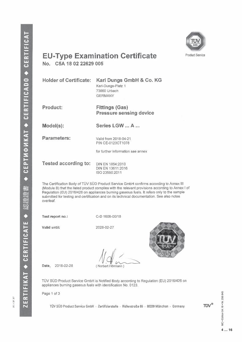
Prüfgrundlage der EU-BaumusterprüfungSpecified requirements of the EU Prototype TestBase d'essai de l'examen de type de l'UECriteri di prova dell'omologazione UE
EN 1854EN 13611ISO 23550
Gültigkeitsdauer/BescheinigungTerm of validity/attestationValidité/certificatDurata della validità/Attestazione
2023-06-13CE0036
2028-02-27CE-0123CT1078
Notifizierte StelleNotified BodyOrganisme notifiéOrganismo notificato
2014/68/EUTÜV SÜD Industrie ServiceGmbH Westendstraße 199D-80686 MünchenGermanyNotified Body number: 0036
(EU) 2016/426TÜV SÜD Product Service GmbH ZertifizierstellenRidlerstraße 65D-80339 MünchenGermanyNotified Body number: 0123
Überwachung des QS-SystemsMonitoring of the QA systemContrôle du système d'assurance qualitéMonitoraggio del sistema QS
Gewähltes Konformitätsverfahren Modul B+DConformity process adopted: Mo-dule B+DProcédure de conformité sélection-née : module B+DProcedura di conformità seleziona-ta: modulo B+D
Dr.-Ing. Karl-Günther Dalsaß, Geschäftsführer / Chief Operating OfficerDirecteur / AmministratoreUrbach, 2018-04-21

3 … 16
MC
• Ed
ition
04.1
8 • N
r. 25
6 84
5
4 … 16
MC
• Ed
ition
04.1
8 • N
r. 25
6 84
5
5 … 16
MC
• Ed
ition
04.1
8 • N
r. 25
6 84
5
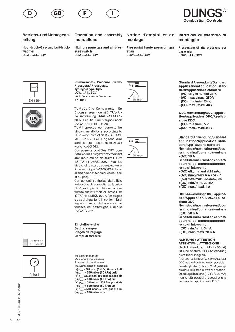
Betriebs- und Montagean-leitung
Hochdruck-Gas- und Luftdruck-wächter LGW…A4.. SGV
Operation and assembly instructions
High pressure gas and air pres-sure switchLGW…A4.. SGV
Notice d'emploi et de montage
Pressostat haute pression gaz et airLGW…A4.. SGV
Max. BetriebsdruckMax. operating pressurePression de service maxi. Max. pressione di esercizio (+) pmax. = 500 mbar (50 kPa) Gas und Luft(-) pmax. = 500 mbar (50 kPa) Luft(+) pmax. = 500 mbar (50 kPa) gas and air(-) pmax. = 500 mbar (50 kPa) air(+) pmax. = 500 mbar (50 kPa) gaz et air(-) pmax. = 500 mbar (50 kPa) air(+) pmax. = 500 mbar (50 kPa) gas et aria(-) pmax. = 500 mbar aria
Druckwächter/ Pressure Switch/Pressostat/ PressostatoTyp/Type/Type/TipoLGW…A4.. SGVnach / acc. / selon / a normeEN 1854
EinstellbereicheSetting rangesPlages de réglageCampi di taratura
Istruzioni di esercizio di montaggio
Pressostato di alta pressione per gas e ariaLGW…A4.. SGV
HR SRB BIH SK
[mbar]
EN 1854
TÜV-geprüfte Komponenten für Biogasanlagen gemäß TÜV-Ar-beitsanweisung IS-TAF 411.MRZ.-2007. Für Bio- und Klärgase nach DVGW Arbeitsblatt G 262.TÜV-inspected components for biogas installations according to TÜV work instruction IS-TAF 411.MRZ.-2007. For biogases and sewage gases according to DVGW worksheet G 262.Composants contrôlés TÜV pour installations à biogaz conformément aux instructions de travail TÜV (IS-TAF 411.MRZ.-2007): Pour les biogaz et le gaz de curage selon la fiche technique DVGW G 262 Union allemande des techniques de l’eau et du gaz).Componenti controllati dall'ufficio tedesco per la sorveglianza tecnica TÜV per impianti di biogas in con-formità alle istruzioni di lavoro TÜV IS-TAF 411.MRZ.-2007. Per biogas e gas di digestione in conformità al foglio di lavoro dell'associazione tedesca dei settori gas e acqua DVGW G 262.
Standard Anwendung/Standard application/Application stan-dard/Applicazione standardNennstrom/nominal current/cou-rant nominal/corrente nominale ~(AC) 10 ASchaltstrom/current on contact/courant de commutation/cor-rente di intervento~(AC) eff., min./mini 20 mA,~(AC) max./maxi. 6 A cos ϕ 1~(AC) max./maxi. 3 A cos ϕ 0,6 =(DC) min./mini. 20 mA=(DC) max./maxi. 1 A
DDC-Anwendung/DDC applica-tion/Application DDC/Applica-zione DDCNennstrom/nominal current/cou-rant nominal/corrente nominale =(DC) 20 mASchaltstrom/current on contact/courant de commutation/cor-rente di intervento=(DC) min./mini. 5 mA=(DC) max./maxi. 20 mA
ACHTUNG / ATTENTIONATTENTION / ATTENZIONENach Anwendung (> 24 V / > 20 mA) ist eine spätere DDC-Anwendung nicht mehr möglich.After application (> 24 V / > 20 mA), a later DDC application is no longer possible.Selon l'application (> 24 V / > 20 mA), une ap-plication DDC ultérieure n'est plus possible.Dopo l'applicazione (> 24 V / > 20 mA) non è più possibile eseguire una successiva applicazione DDC.
Standard Anwendung/Standard application/Application stan-dard/Applicazione standard~(AC) eff., min./mini 24 V, ~(AC) max. /maxi. 250 V=(DC) min./mini. 24 V, =(DC) max. /maxi. 48 V
DDC-Anwendung/DDC applica-tion/Application DDC/Applica-zione DDC=(DC) min./mini. 5 V, =(DC) max. /maxi. 24 V

6 … 16
MC
• Ed
ition
04.1
8 • N
r. 25
6 84
5
UmgebungstemperaturAmbient temperatureTempérature ambianteTemperatura ambiente 0 °C … +70 °C
MediumstemperaturMedium temperatureTempérature du fluideTemperatura fluido 0 °C … +70 °C
LagertemperaturStorage temperatureTempérature de stockageTemperatura stoccaggio –30 °C … +80 °C
Schutzart / Degree of protectionProtection / Protezione LGW…A4.. SGV IP 65 nach / acc. / selon / a norme IEC 529 (EN 60529)
Medium/Medium/Fluide/Fluido vettoresiehe Seite 5see page 5voir page 10vedi pagina 10
Eine anlagenspezifische Gasanaly-se zur Auswahl der Sondergaskom-ponenten ist zwingend notwendig.Produkte können eine verringerte Lebensdauer haben, wenn die Gas-qualität im Betrieb von der durchge-führten Gasanalyse abweicht.
Installation-specific gas analysis for selecting the special gas component is absolutely required.Products may have a shorter service life if the gas quality during operation differs from the gas analysis that was carried out.
Une analyse de gaz spécifique aux installations permettant de sélectionner les composants du gaz particulier est obligatoire.Des produits peuvent avoir une durée de vie réduite si la qualité du gaz lors de l'utilisation diffère de l'analyse de gaz effectuée.
Un'analisi del gas specifica dell'im-pianto è imprescindibile per la scelta dei componenti per gas speciali.I prodotti possono avere una durata utile ridotta se la qualità del gas diverge durante il funzionamento dall'analisi del gas eseguita.

7 … 16
MC
• Ed
ition
04.1
8 • N
r. 25
6 84
5
G 1/4
7 Nm
Einbaumaße / Dimensions / Cotes d'encombrement / Dimensioni [mm]LGW…A4
M 4
2,5 Nm
DNRp
Mmax.
Tmax.
[Nm] t ≤ 10 s
[Nm] t ≤ 10 s
Gerät darf nicht als Hebel be-nutzt werdenDo not use unit as lever.Ne pas utiliser le pressostat comme un levier.L'apparecchio non deve essere usato come leva.
max. Drehmomente / Systemzubehörmax. torque / System accessoriesmax. couple / Accessoires du systèmemax. coppie / Accessorio di sistema
Geeignetes Werkzeug einsetzen! Please use proper tools! Utiliser des outils adaptés! Impiegare gli attrezzi adeguati!
81/4
35
20
61/8
25
15
[Nm]
18
19
Chrome S
teel
Mad
e in G
erman
y
M 20 x 1,5 oder Steckanschluß für Leitungsdose nach DIN EN 175 301-803M20 x 1.5 or plug-type connection for cable socket according to DIN EN 175 301-803M20 x 1,5 ou fiche pour boîtier suivant DIN EN 175 301-803M20 x 1,5 oppure collegamento a spina per presa di rete a norme DIN EN 175 301-803
ø 2,5 x 9 tief für Gerätestecker DIN EN 175 301-8032.5 x 9 dia. deep for DIN EN 175 301-803 equipment plugø 2,5 x 9 de profond pour embase de connecteur DIN EN 175 301-803foro per spina ø 2,5 x 9 DIN EN 175 301-803
Meßstutzen, integriert ø 9Measurement nozzle, integratedPrise de pression intégréepresa pressione, integrata
4 x ø 4,2für Schrauben M4 ISO 1201, ISO 4762for M4 ISO 1201, ISO 4762 screwspour vis M4 ISO 1201, ISO 4762per viti M4 ISO 1201, ISO 4762
Druckanschluß G 1/4G 1/4 pressure connectionRaccordement du fluide G 1/4attacco pressione G 1/4
Druckanschluß G 1/8G 1/8 pressure connectionRaccordement du fluide G 1/8attacco pressione G 1/8
Made in Germany
7653,75 (LK 76)
72
G 1
/4
+
58,6
37,4 10
,3
18,5
SW 2
1
StandardeinbaulageStandard installation positionPosition de montage standardPosizione standard
Bei waagerechtem Einbau schaltet der Druckwächter bei einem um ca. 0,5 mbar höheren Druck.In the horizontal installation position the switching pressure is increased by approx. 0.5 mbar.Monté horizontalement, le pressostat commute à une pression d´environ 0,5 mbar plus élevée.Con montaggio orizzontale il pressostato scatta ad pressione superiore di circa 0,5 mbar.
Bei Einbau waagerecht über Kopf schaltet der Druckwächter bei einem um ca. 0,5 mbar niedrigeren Druck.When the pressure switch is mounted horizontally overhead, its switching pressure decreases by approx. 0.5 mbar.Monté horizontalement à l´envers, le pressostat commute à une pression d´environ 0,5 mbar moins élevée.Con montaggio orizzontale capovolto il pressostato scatta ad una pressione inferiore di circa 0,5 mbar.
Bei Einbau in einer Zwischeneinbaulage schaltet der Druckwächter bei einem vom eingestellten Sollwert maximal ± 0,5 mbar abweichenden Druck.When the pressure switch is mounted in an intermediate position, its switching pressure deviates by max. ± 0.5 mbar from the setpoint.Monté dans une position intermédiaire, le pressostat commute à une pression d'un maximum de ± 0,5 mbar par rapport à la valeur de consigne réglée.Con il montaggio in una posizione intermedia il pressostato scatta ad una pressione diversa da quella nominale di max. ± 0,5 mbar.
Einbaulage / Installation position / Position de montage / Posizione de montaggio
G 1/8
5 Nm
ø 3
1,2 Nm
M3
1,2 Nm
8 … 16
MC
• Ed
ition
04.1
8 • N
r. 25
6 84
5
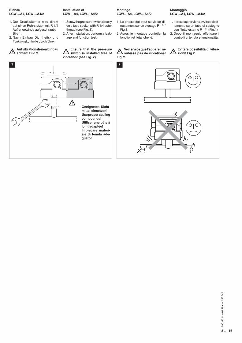
EinbauLGW…A4, LGW…A4/2
1. Der Druckwächter wird direkt auf einen Rohrstutzen mit R 1/4 Außengewinde aufgeschraubt.
Bild 1.2. Nach Einbau Dichtheits- und
Funktionskontrolle durchführen.
Auf vibrationsfreien Einbau achten! Bild 2.
1
Installation ofLGW…A4, LGW…A4/2
1. Screw the pressure switch directly on a tube socket with R 1/4 outer thread (see Fig. 1).
2. After installation, perform a leak-age and function test.
Ensure that the pressure switch is installed free of
vibration! (see Fig. 2).
MontageLGW…A4, LGW…A4/2
1. Le pressostat peut se visser di-rectement sur un piquage R 1/4" Fig.1.
2. Après le montage contrôler la fonction et l'étanchéité.
Veiller à ce que l'appareil ne subisse pas de vibrations!
Fig. 2.
MontaggioLGW…A4, LGW…A4/2
1. Il pressostato viene avvitato diret-tamente su un tubo di sostegno con filetto esterno R 1/4 (Fig.1)
2. Dopo il montaggio effettuare i controlli di tenuta e funzionalità.
Evitare possibilità di vibra-zioni! Fig 2.
2
Geeignetes Dicht-mittel einsetzen!Use proper sealing compounds!Utiliser une pâte à joint adaptée!Impiegare materi-ale di tenuta ade-guato!
9 … 16
MC
• Ed
ition
04.1
8 • N
r. 25
6 84
5
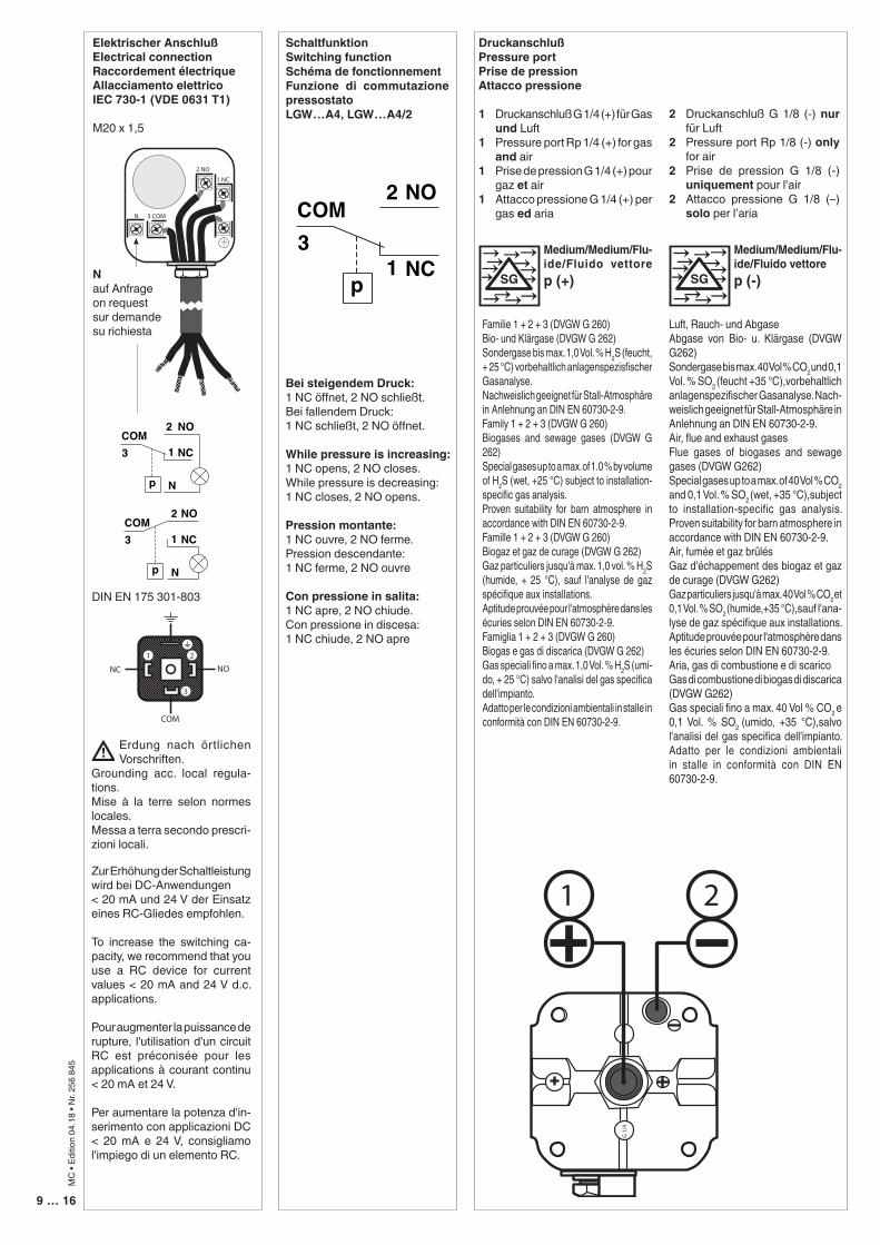
Elektrischer AnschlußElectrical connectionRaccordement électriqueAllacciamento elettricoIEC 730-1 (VDE 0631 T1)
M20 x 1,5
SchaltfunktionSwitching functionSchéma de fonctionnementFunzione di commutazione pressostato LGW…A4, LGW…A4/2
Bei steigendem Druck:1 NC öffnet, 2 NO schließt.Bei fallendem Druck:1 NC schließt, 2 NO öffnet.
While pressure is increasing:1 NC opens, 2 NO closes.While pressure is decreasing:1 NC closes, 2 NO opens.
Pression montante:1 NC ouvre, 2 NO ferme.Pression descendante:1 NC ferme, 2 NO ouvre
Con pressione in salita:1 NC apre, 2 NO chiude.Con pressione in discesa:1 NC chiude, 2 NO apre
Nauf Anfrageon requestsur demandesu richiesta
DruckanschlußPressure portPrise de pressionAttacco pressione
1 Druckanschluß G 1/4 (+) für Gas und Luft
1 Pressure port Rp 1/4 (+) for gas and air
1 Prise de pression G 1/4 (+) pour gaz et air
1 Attacco pressione G 1/4 (+) per gas ed aria
2 Druckanschluß G 1/8 (-) nur für Luft
2 Pressure port Rp 1/8 (-) only for air
2 Prise de pression G 1/8 (-) uniquement pour l’air
2 Attacco pressione G 1/8 (–) solo per l’aria
Medium/Medium/Flu-ide/Fluido vettore p (+)
Familie 1 + 2 + 3 (DVGW G 260)Bio- und Klärgase (DVGW G 262)Sondergase bis max. 1,0 Vol. % H2S (feucht, + 25 °C) vorbehaltlich anlagenspezisfischer Gasanalyse. Nachweislich geeignet für Stall-Atmosphäre in Anlehnung an DIN EN 60730-2-9.Family 1 + 2 + 3 (DVGW G 260)Biogases and sewage gases (DVGW G 262)Special gases up to a max. of 1.0 % by volume of H2S (wet, +25 °C) subject to installation-specific gas analysis.Proven suitability for barn atmosphere in accordance with DIN EN 60730-2-9.Famille 1 + 2 + 3 (DVGW G 260)Biogaz et gaz de curage (DVGW G 262)Gaz particuliers jusqu'à max. 1,0 vol. % H2S (humide, + 25 °C), sauf l'analyse de gaz spécifique aux installations.Aptitude prouvée pour l'atmosphère dans les écuries selon DIN EN 60730-2-9.Famiglia 1 + 2 + 3 (DVGW G 260)Biogas e gas di discarica (DVGW G 262)Gas speciali fino a max. 1,0 Vol. % H2S (umi-do, + 25 °C) salvo l'analisi del gas specifica dell'impianto. Adatto per le condizioni ambientali in stalle in conformità con DIN EN 60730-2-9.
Medium/Medium/Flu-ide/Fluido vettorep (-)
Luft, Rauch- und AbgaseAbgase von Bio- u. Klärgase (DVGW G262)Sondergase bis max. 40 Vol % CO2 und 0,1 Vol. % SO2 (feucht +35 °C),vorbehaltlich anlagenspezifischer Gasanalyse. Nach-weislich geeignet für Stall-Atmosphäre in Anlehnung an DIN EN 60730-2-9.Air, flue and exhaust gasesFlue gases of biogases and sewage gases (DVGW G262)Special gases up to a max. of 40 Vol % CO2 and 0,1 Vol. % SO2 (wet, +35 °C),subject to installation-specific gas analysis. Proven suitability for barn atmosphere in accordance with DIN EN 60730-2-9.Air, fumée et gaz brûlésGaz d'échappement des biogaz et gaz de curage (DVGW G262)Gaz particuliers jusqu'à max. 40 Vol % CO2 et 0,1 Vol. % SO2 (humide,+35 °C),sauf l'ana-lyse de gaz spécifique aux installations. Aptitude prouvée pour l'atmosphère dans les écuries selon DIN EN 60730-2-9.Aria, gas di combustione e di scaricoGas di combustione di biogas di discarica (DVGW G262)Gas speciali fino a max. 40 Vol % CO2 e 0,1 Vol. % SO2 (umido, +35 °C),salvo l'analisi del gas specifica dell'impianto. Adatto per le condizioni ambientali in stalle in conformità con DIN EN 60730-2-9.
DIN EN 175 301-803
p
COMNO
NC
2
13
COMNO
NC
2
1
p
3
N
COMNO
NC
2
1
p
3
N
p
COMNO
NC
2
13
COMNO
NC
2
1
p
3
N
COMNO
NC
2
1
p
3
N
p
COMNO
NC
2
13
COMNO
NC
2
1
p
3
N
COMNO
NC
2
1
p
3
N
Erdung nach örtlichen Vorschriften.
Grounding acc. local regula-tions.Mise à la terre selon normes locales.Messa a terra secondo prescri-zioni locali.
Zur Erhöhung der Schaltleistung wird bei DC-Anwendungen < 20 mA und 24 V der Einsatz eines RC-Gliedes empfohlen.
To increase the switching ca-pacity, we recommend that you use a RC device for current values < 20 mA and 24 V d.c. applications.
Pour augmenter la puissance de rupture, l'utilisation d'un circuit RC est préconisée pour les applications à courant continu < 20 mA et 24 V.
Per aumentare la potenza d'in-serimento con applicazioni DC < 20 mA e 24 V, consigliamo l'impiego di un elemento RC.
10 … 16
MC
• Ed
ition
04.1
8 • N
r. 25
6 84
5
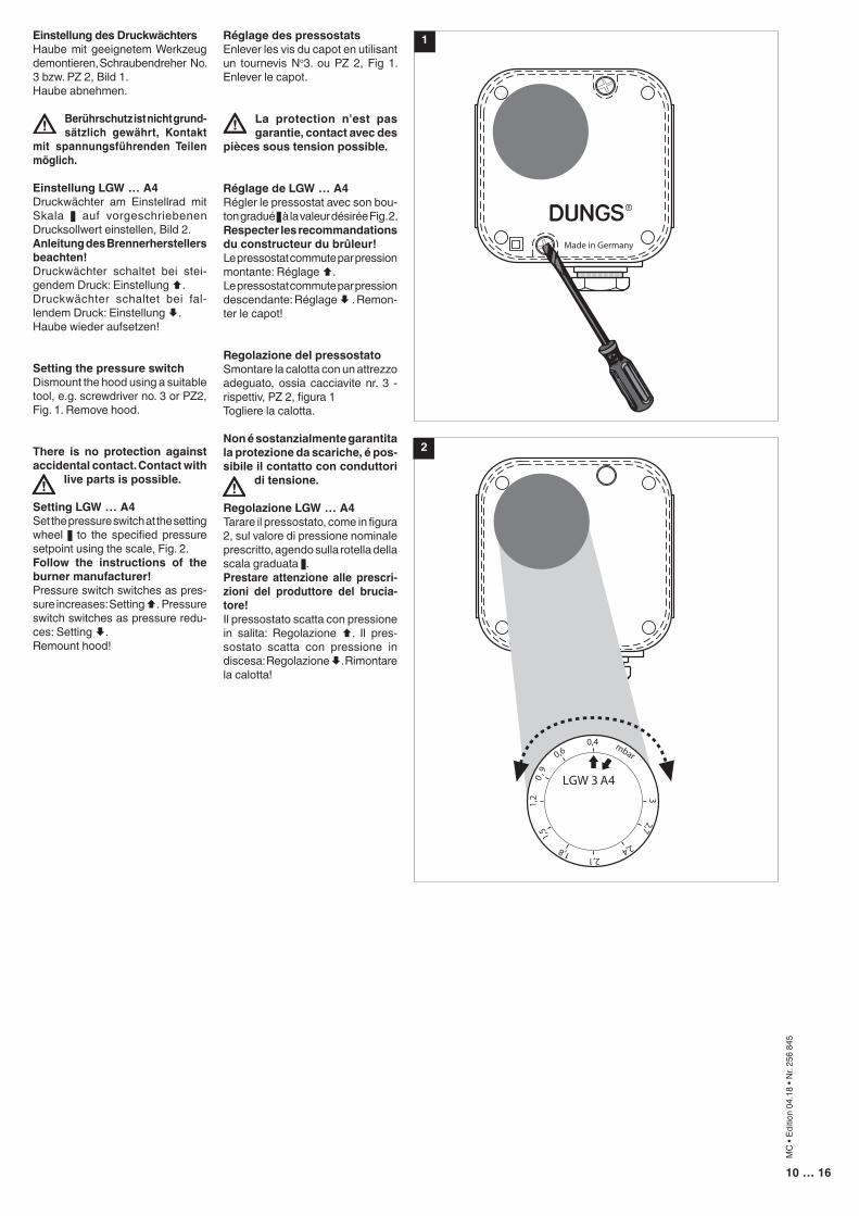
Réglage des pressostatsEnlever les vis du capot en utilisant un tournevis No3. ou PZ 2, Fig 1. Enlever le capot.
La protection n'est pas garantie, contact avec des
pièces sous tension possible.
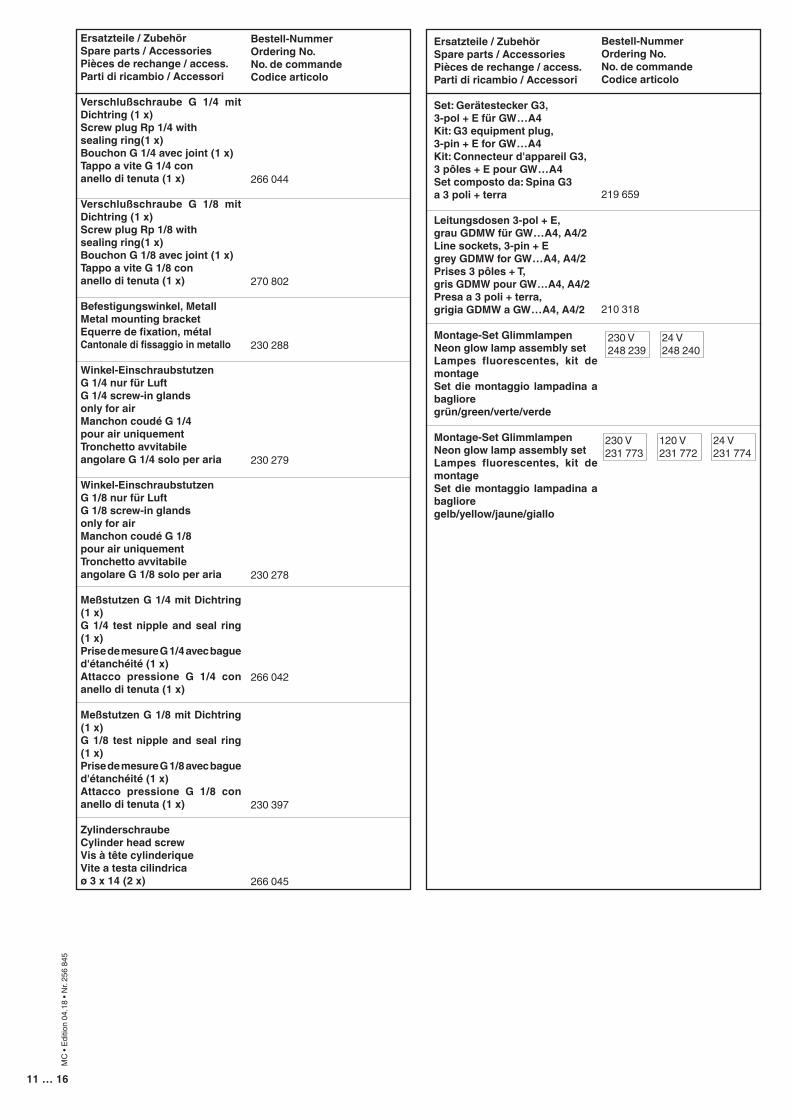
Réglage de LGW … A4Régler le pressostat avec son bou-ton gradué z à la valeur désirée Fig. 2.Respecter les recommandations du constructeur du brûleur!Le pressostat commute par pression montante: Réglage Ç.Le pressostat commute par pression descendante: Réglage È . Remon-ter le capot!
Regolazione del pressostatoSmontare la calotta con un attrezzo adeguato, ossia cacciavite nr. 3 - rispettiv, PZ 2, figura 1Togliere la calotta.
Non é sostanzialmente garantita la protezione da scariche, é pos-sibile il contatto con conduttori
di tensione.
Regolazione LGW … A4Tarare il pressostato, come in figura 2, sul valore di pressione nominale prescritto, agendo sulla rotella della scala graduata z.Prestare attenzione alle prescri-zioni del produttore del brucia-tore!Il pressostato scatta con pressione in salita: Regolazione Ç. Il pres-sostato scatta con pressione in discesa: Regolazione È. Rimontare la calotta!
Einstellung des DruckwächtersHaube mit geeignetem Werkzeug demontieren, Schraubendreher No. 3 bzw. PZ 2, Bild 1.Haube abnehmen.
Berührschutz ist nicht grund-sätzlich gewährt, Kontakt
mit spannungsführenden Teilen möglich.
Einstellung LGW … A4Druckwächter am Einstellrad mit Skala z auf vorgeschriebenen Drucksollwert einstellen, Bild 2.Anleitung des Brennerherstellers beachten!Druckwächter schaltet bei stei-gendem Druck: Einstellung Ç. Druckwächter schaltet bei fal-lendem Druck: Einstellung È.Haube wieder aufsetzen!
Setting the pressure switch Dismount the hood using a suitable tool, e.g. screwdriver no. 3 or PZ2, Fig. 1. Remove hood.
There is no protection against accidental contact. Contact with
live parts is possible.
Setting LGW … A4Set the pressure switch at the setting wheel z to the specified pressure setpoint using the scale, Fig. 2.Follow the instructions of the burner manufacturer!Pressure switch switches as pres-sure increases: Setting Ç. Pressure switch switches as pressure redu-ces: Setting È.Remount hood!
1
2
11 … 16
MC
• Ed
ition
04.1
8 • N
r. 25
6 84
5
Ersatzteile / ZubehörSpare parts / AccessoriesPièces de rechange / access.Parti di ricambio / Accessori
Verschlußschraube G 1/4 mit Dichtring (1 x)Screw plug Rp 1/4 withsealing ring(1 x)Bouchon G 1/4 avec joint (1 x)Tappo a vite G 1/4 conanello di tenuta (1 x)
Verschlußschraube G 1/8 mit Dichtring (1 x)Screw plug Rp 1/8 withsealing ring(1 x)Bouchon G 1/8 avec joint (1 x)Tappo a vite G 1/8 conanello di tenuta (1 x)
Befestigungswinkel, MetallMetal mounting bracketEquerre de fixation, métalCantonale di fissaggio in metallo
Winkel-Einschraubstutzen G 1/4 nur für LuftG 1/4 screw-in glandsonly for airManchon coudé G 1/4pour air uniquementTronchetto avvitabile angolare G 1/4 solo per aria
Winkel-Einschraubstutzen G 1/8 nur für LuftG 1/8 screw-in glandsonly for airManchon coudé G 1/8pour air uniquementTronchetto avvitabile angolare G 1/8 solo per aria
Meßstutzen G 1/4 mit Dichtring (1 x)G 1/4 test nipple and seal ring (1 x)Prise de mesure G 1/4 avec bague d'étanchéité (1 x)Attacco pressione G 1/4 con anello di tenuta (1 x)
Meßstutzen G 1/8 mit Dichtring (1 x)G 1/8 test nipple and seal ring (1 x)Prise de mesure G 1/8 avec bague d'étanchéité (1 x)Attacco pressione G 1/8 con anello di tenuta (1 x)
ZylinderschraubeCylinder head screwVis à tête cylinderiqueVite a testa cilindricaø 3 x 14 (2 x)
Bestell-NummerOrdering No.No. de commandeCodice articolo
266 044
270 802
230 288
230 279
230 278
266 042
230 397
266 045
Ersatzteile / ZubehörSpare parts / AccessoriesPièces de rechange / access.Parti di ricambio / Accessori
Set: Gerätestecker G3, 3-pol + E für GW…A4Kit: G3 equipment plug, 3-pin + E for GW…A4Kit: Connecteur d'appareil G3, 3 pôles + E pour GW…A4Set composto da: Spina G3 a 3 poli + terra
Leitungsdosen 3-pol + E,grau GDMW für GW…A4, A4/2Line sockets, 3-pin + Egrey GDMW for GW…A4, A4/2Prises 3 pôles + T, gris GDMW pour GW…A4, A4/2Presa a 3 poli + terra, grigia GDMW a GW…A4, A4/2
Montage-Set GlimmlampenNeon glow lamp assembly setLampes fluorescentes, kit de montageSet die montaggio lampadina a baglioregrün/green/verte/verde
Montage-Set GlimmlampenNeon glow lamp assembly setLampes fluorescentes, kit de montageSet die montaggio lampadina a baglioregelb/yellow/jaune/giallo
Bestell-NummerOrdering No.No. de commandeCodice articolo
219 659
210 318
230 V248 239
24 V248 240
230 V231 773
120 V231 772
24 V231 774
12 … 16
MC
• Ed
ition
04.1
8 • N
r. 25
6 84
5
Rohrleitungsdichtheits-prüfung: Kugelhahn vor dem Druckwächter schließen.
Nach Abschluß von Ar-beiten am Druckwäch-ter: Dichtheitskontrolle und Funktionskontrolle durchführen.
Niemals Arbeiten durch-führen, wenn Gasdruck oder Spannung anliegt. Offenes Feuer vermeiden. Örtliche Vorschriften be-achten.
Bei Nichtbeachtung der Hinweise sind Personen- oder Sachfolgeschäden denkbar.
Pipeline leakage test: close ball valve up-streamof the pressure switch.
On completion of work on the pressure switch, perform a leakage and function test.
Never perform work if gas pressure or power is applied. No naked flame. Observe local regulat-ions.
If these instructions are not heeded, the result may be personal injury or damage to property.
En cas de non-respect de ces instructions, des dommages corporels ou matériels sont possible.
Ne jamais effectuer des travaux sous pression ou sous tension. Eviter toute flamme ouverte. Observer les réglementations.
Une fois les travaux sur le pressostat terminés, procéder toujours à un contrôle d'étanchéité et de fonctionnement.
Contrôle de l'étanchéité de la conduite: fermer le robinet à boisseau sphèrique avant le pres-sostat.
Per la prova di tenuta delle tubature: chiudere il rubinetto a sfera davanti al pressostato.
Al termine dei lavori effet-tuati su un pressostato: predisporre un controllo sia della tenuta che del funzionamento.
In nessun caso si debbono effettuare lavori in presen-za di pressione gas o di tensione elettrica. Evitare i fuochi aperti e osservare le prescrizioni di sicurezza locali.La non osservanza di quanto suddetto può im-plicare danni a persone o cose.
Kondensat darf nicht in das Gerät gelangen. Bei Minustemperaturen, durch Vereisung Fehl-funktion/Ausfall mög-lich.
Eviter l'entrée de conden-sat dans le pressostat, une prise en glace par température négative nuirait à son fonction-nement.
Do not allow condensate to flow into the equipment. In case of sub-zero tem-peratures, malfunction or equipment failure may be possible due to icing.
Nell' apparecchio non deve infiltrarsi alcuna condensa. Alle tempera-ture negative sarebbe-ro possibili disfunzioni dovute a formazione di ghiaccio.
Arbeiten am Druckwäch-ter dürfen nur von Fach-personal durchgeführt werden.
Seul du personnel spécia-lisé peut effectuer des tra-vaux sur le pressostat.
Work on the pressu-re switch may only be performed by specialist staff.
Qualsiasi operazione effettuata sul presso-stato deve essere fatta da parte di personale competente.
Safetyfirst
O.K.
Silikonöle und flüchtige Silikonbestandteile (Siloxane) in der Umgebung vermeiden. Fehlfunktion / Ausfall möglich.
Avoid silicone oils and volatile silicones (siloxanes) in the environment. Malfunction/failure possible.
Eviter les huiles de silicone et les eléments de silicone volatils (siloxanes) dans l’environnement. Dysfonctionnement / panne possibles.
Evitare oli siliconici e componenti siliconici volatili (silossani) nell’ambiente. Possibile disfunzione / guasto.
Alle Einstellungen und Einstellwerte nur in Über-einstimmung mit der Be-triebsanleitung des Kes-sel-/Brennerherstellers ausführen.
Any adjustment and appli-cation-specific adjustment values must be made in accordance with the appli-ance-/boiler manufacturers instructions.
Effectuer tous les régla-ges et réaliser les valeurs de réglage uniquement selon le mode d'emploi du fabricant de chaudières et de brûleurs.
Realizzare tutte le impo-stazioni e i valori imposta-ti solo in conformità alle istruzioni per l'uso del costruttore della caldaia/del bruciatore.
13 … 16
MC
• Ed
ition
04.1
8 • N
r. 25
6 84
5
Sicherheitsrelevante Komponenten sind ge-mäß der Landwirtschaft-lichen Berufsgenossen-schaft / Deutschland, technische Information Nr. 4, wöchentlich auf Funktion und Dichtheit zu prüfen und bei Aus-fall sofort, spätestens jedoch nach Erreichen ihrer Nutzungsdauer aus-zutauschen.
Funktionsprüfungeinmal pro Woche und nach Betriebsstörung
a) Dichtheitsprüfung Die Armaturenteile im Be-trieb mit geeignetem Leck-spray auf Dichtheit prüfen.
b) Schaltpunktprüfung
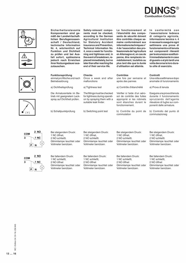
Bei steigendem Druck:1 NC öffnet,2 NO schließt.Glimmlampe leuchtet oder Voltmeter benützen.
Bei fallendem Druck:1 NC schließt,2 NO öffnetGlimmlampe leuchtet oder Voltmeter benützen.
[ V ]
COMNO
NC
2
1
p
3
N
COMNO
NC
2
1
p
3
N
Safety-relevant compo-nents must be checked, according to the German Agricultural Institution for Statutory Accident Insurance and Prevention, Technical Information No. 4, once a week for functio-ning and tightness and, in the event of breakdown, re-placed immediately, but no later than after reaching the end of their service life.
ChecksOnce a week and after malfunctions
a) Tightness test The fittings must be checked for tightness during operati-on by spraying them with a suitable leak finder.
b) Switching point test
Bei steigendem Druck:1 NC öffnet,2 NO schließt.Glimmlampe leuchtet oder Voltmeter benützen.
Bei fallendem Druck:1 NC schließt,2 NO öffnetGlimmlampe leuchtet oder Voltmeter benützen.
Le fonctionnement et l'étanchéité des compo-sants de sécurité doivent être contrôlés chaque se-maine conformément aux informations techniques n° 4 de l'association des pro-fessionnels de l'agriculture en Allemagne et, en cas de panne, être remplacés im-médiatement, toutefois au plus tard dès que la durée d'utilisation est atteinte.
Contrôles une fois par semaine et après des pannes
a) Contrôle d'étanchéité Vérifier à l'aide d'un aéro-sol de contrôle des fuites approprié si les robinets sont étanches durant le fonctionnement.
b) Contrôle du point de commutation
Bei steigendem Druck:1 NC öffnet,2 NO schließt.Glimmlampe leuchtet oder Voltmeter benützen.
Bei fallendem Druck:1 NC schließt,2 NO öffnetGlimmlampe leuchtet oder Voltmeter benützen.
I n c o n fo r m i t à c o n l'associazione tedesca di categoria agricola, informazione tecnica n. 4 è necesario eseguire ogni settimana una prova di funzionamento e di tenuta sui componenti rilevanti per la sicurezza e sostituir-li immediatamente in caso di guasto o al più tardi una volta decorsa la loro dura-ta utile di esercizio.
ControlliUna volta a settimana e dopo anomalie di funzionamento
a) Prova di tenuta Eseguire una prova di tenuta durante il funzionamento spruzzando dell'agente rilevatore di fughe sui com-ponenti delle armature.
b) Controllo del punto di commutazioneg
Bei steigendem Druck:1 NC öffnet,2 NO schließt.Glimmlampe leuchtet oder Voltmeter benützen.
Bei fallendem Druck:1 NC schließt,2 NO öffnetGlimmlampe leuchtet oder Voltmeter benützen.

14 … 16
MC
• Ed
ition
04.1
8 • N
r. 25
6 84
5
Die Druckgeräterichtlinie (PED) und die Richtlinie über die Gesamtenergieef-fizienz von Gebäuden (EPBD) fordern eine regel-mässige Überprüfung der Wärmeerzeuger zur lang-fristigen Sicherstellung von hohen Nutzungsgraden und somit geringster Um-weltbelastung. Es besteht die Notwen-digkeit sicherheitsre-levante Komponenten nach Erreichen ihrer Nutzungsdauer aus-zutauschen:
The Pressure Equipment Directive (PED) and the Energy Performance of Buildings Directive (EPBD) require a periodic inspec-tion of heat generators in order to ensure a high degree of efficiency over a long term and, conse-quently, the least environ-mental pollution. It is necessary to re-place safety-relevant components after they have reached the end of their useful life:
La directive concernant les chauffe-bains à pression (PED) et la directive sur la performance énergétique des bâtiments (EPBD) exigent une vérification régulière des générateurs de chaleur afin de garantir à long terme des taux d‘utilisation élevés et par conséquent une charge envi-ronnementale minimum. Il est nécessaire de rempla-cer les composants relatifs à la sécurité lorsqu‘ils ont atteint la fin de leur vie utile:
La direttiva per apparecchi a pressione (PED) e la direttiva per l‘efficienza dell‘energia totale per edifici (EPBD), esi-gono il controllo regolare de-gli generatori di calore per la garanzia a lungo termine di un alto grado di rendimento e con ciò di basso inquinamen-to ambientale. Ciò rende necessaria la sostituzione di componen-ti rilevanti dal punto di vi-sta della sicurezza alla scadenza della loro durata di utilizzazione:
Änderungen, die dem technischen Fortschritt dienen, vorbehalten / We reserve the right to make modifications in the course of technical development.Sous réserve de tout modification constituant un progrès technique / Ci riserviamo qualsiasi modifica tecnica e costruttiva
Sicherheitsrelevante KomponenteSafety relevant componentComposant relatif à la sécuritéComponenti rilevanti dal punto di vista della sicurezza
Konstruktionsbedingte LebensdauerDesigned LifetimeDurée de vie prévueDurata di vita di progetto
CEN-NormCEN-StandardCEN-NormeCEN-Norma
ZyklenzahlOperating cyclesCycle d’opérationNumero di cicli di funzionamento di progetto
Zeit [Jahre]Time [years]Durée [année]Periodo [anni]
Ventilprüfsysteme / Valve proving systems Systèmes de contrôle de vannes / Sistemi di controllo valvole 250.000 10 EN 1643
Gas/GazDruckwächter / Pressure switch / Manostat / Pressostati 50.000 10 EN 1854
Luft/Air/AriaDruckwächter / Pressure switch / Manostat / Pressostati 250.000 10 EN 1854
Gasmangelschalter / Low gas pressure switchPressostat gaz basse pression /Pressostati gas di minima pressi-one
N/A 10 EN 1854
Feuerungsmanager / Automatic burner controlDispositif de gestion de chauffage / Gestione bruciatore 250.000 10
EN 298 (Gas/Gaz)EN 230 (Öl/Oil/
Mazout/OlioUV-Flammenfühler1
Flame detector (UV probes)1
Capteur de flammes UV1
Sensore fiamma UV1N/A
10.000Betriebsstunden Operating hours
Heures de service Ore di esercizio
---
Gasdruckregelgeräte1 / Gas pressure regulators1
Dispositifs de réglage de pression du gaz1
Regolatori della pressione del gas1N/A 15 EN 88-1
EN 88-2
Gasventil mit Ventilprüfsystem2
Gas valve with valve testing system2
Vanne de gaz avec système de contrôle de vanne2 Valvola del gas con sistema di controllo valvola2
nach erkanntem Fehlerafter error detection
après détection d’erreurdopo segnalazione di errore
EN 1643
Gasventil ohne Ventilprüfsystem2
Gas valve without valve testing system2
Vanne de gaz sans système de contrôle de vanne2
Valvola del gas senza sistema di controllo valvola2
50.000 - 200.000abhängig von der Nennweite
depends on diameterselon la taille
a seconda della dimensione di connessione
10 EN 161
Gas-Luft-Verbundsysteme / Gas-air ratio control systemSystèmes combinés gaz/air / Sistemi di miscelazione gas-aria N/A 10 EN 88-1
EN 12067-2
1 Nachlassende Betriebseigenschaften wegen Alterung / Performance decrease due to ageing Réduction de performance due au viellissement / Riduzione delle prestazioni dovuta all’invecchiamento2 Gasfamilien II, III / Gas families II, III / Familles de gaz II, III / per i gas delle famiglie II, IIIN/A nicht anwendbar / not applicable / ne peut pas être utilisé / non può essere usato
Karl Dungs GmbH & Co. KGPostfach 12 29D-73602 Schorndorfe-mail [email protected] www.dungs.com
Karl Dungs GmbH & Co. KGKarl-Dungs-Platz 1D-73660 Urbach, GermanyTelefon +49 (0)7181-804-0Telefax +49 (0)7181-804-166
HausadresseHead Offices and FactoryUsine et Services AdministratifsAmministrazione e Stabilimento
BriefadressePostal addressAdresse postaleIndirizzare la corrispondenza a
HR SRB BIH SK

15 … 16
MC
• Ed
ition
04.1
8 • N
r. 25
6 84
5

16 … 16
MC
• Ed
ition
04.1
8 • N
r. 25
6 84
5
Karl Dungs GmbH & Co. KGPostfach 12 29D-73602 Schorndorfe-mail [email protected] www.dungs.com
Karl Dungs GmbH & Co. KGKarl-Dungs-Platz 1D-73660 Urbach, GermanyTelefon +49 (0)7181-804-0Telefax +49 (0)7181-804-166
HausadresseHead Offices and FactoryUsine et Services AdministratifsAmministrazione e Stabilimento
BriefadressePostal addressAdresse postaleIndirizzare la corrispondenza a