xxxxxx - nasa.4 system occurred due to braze cracks at the peripheral plato-bar joints in the...
TRANSCRIPT

NASA Technical Memorandum 79091
(NASA-TH-79091) EVALUATION OF & BRAYTON N79-20217 .CYCLE RECUPERATOB AFTER 21t000 HOURS OF
' GROUND TESTING (NASA) 28 p UC A03/HF A01CSCL 11F Unclas
: _ G3/26 17060
! EVALUATIONOFA BRAYI'ONCYCLERECUPERATOR
• AFTER21,000HOURSOFGROUNDTESTING
Thomas J. Moore
: Lewis Research Center _,
_ Cleveland, OhioCf
February 1979
• 9' J
¢
!
\
L ._ #
' " XXXXXX
https://ntrs.nasa.gov/search.jsp?R=19790012046 2018-05-28T21:39:25+00:00Z

1,
lr
After ground testing a Brayton cycle system for 21 000 hours, the _e 347
stainless steel, Ni-base brazed recuperator and assoc_ted ducting were removedfor metallogr_hic examination. A_so examined were a stainless-steel/Hastel]oy Xbellows and an elbow of Hastelloy X ducting which was exposed to 11 000 hours ofservice. The examination indicated that manufae_re: of the recuperator includingfltop and brazing ol the counterflow, plate-fin core was well dc_e. The recuperator
. operated satisfactorily in that 21 000 _mrs of grotmd testing were accomplished.However) loss of the krypton working fluid and subsequent air contamination of the
u_
,.4 system occurred due to braze cracks at the peripheral plato-bar Joints in the recu-perator. Attempts to repair these leaks were not completely successful. At the hotend of the recupera)_)r, the 0° 10-ram-thick fins were oxidized through the full thick-ness. Operation above the 6'/5o C hot end design temperaturo was probably a con-tribating factor to fin oxidation. At midlength and at the cold (compressor) end, nofin oxidation was observed. The stainless-steel ducting, stalnless-steel/Hastelloy Xbellows, snd HasteUoy X duc'.ing operated satisfactorily, although some loss inductility was observed in the Hastelloy X ducting.
INTRODUCTION
The NASA Lewi_ Research Center ires beon actively involved in the developmentof a closed Brayton cycle, power conversion system, for space applications (ref. 1).Ground testing has been conducted to give assurance that the Brayton system willoperate satisfactorily in space. No apparent wear or failure mode that would preventattainment of the 5-year life objective was found during inspection of two Braytonrotating (i. e., turbine-alternator-compressor) units after 21 000 br of operation(ref. 1). The recuperator, however, experienced leakage problems during the leng-term test, with sipfficant loss of the primary working fluid, krypton.
An evaluation o" the recuperator from the Brayton (unit 2, "B") engine wasundertaken to asses_ overall structural integrity after the 21 000-hour exposure.
i The primary purpose was to evaluate the condition of the type 34"/stainless-steelplate-and-fin core material, includln_ the Ni-baso brazed joints. Metallographlcexz_,uination was also conducted on the associated type 34'/ducting. A type 34'//
, Hastelloy X bellows and Hastelloy X ducting on the hot (tu_ bine) end of the recuper-ator, which saw 11 000 hours of service, were also examined. In the ducting and
• bellows investigations, primary emphasis was placed on deter-mining the quality ofthe weld Joi_ts. The results of the examination of the recul_erator and ducting aredocumented in this report.
RECUPERATOR FABRICATION AND OPERA rION
In the intended application, the Brayton Engine is designed to operate continuouslywith a closed loop of He-Xe working fluid in the vacuum of, s_eoe for 5 years. The
XXXXXX-O02

ground test discussed herein was conducted in air using krypton working flui_ forreasons of economy. A schematic of the Brayton power conversion system is shownin figure 1. Energy for the ground test was supplied to the loop by means of an elec-tric heat source (ref. 2). The turbine inlet temperature was 870° C, and the turbinescroll discharge temperature was 760 ° C (ref. 1). Design conditions for the recu-
• perator (taken from ref. 3) are shown in table 1. A silicone llq'_id (Dow Coming 200)was used as the liquid coolant in the waste beat exchanger. The design conditions
. specify an inlet temperature at the hot (turbine) end of the recuperator o." 675° C.
_ On the cold (compressor) end an inlet temperature of 140° C was specified. Dimen-sions of the counterflow section (fig. 2) are also shown in table 1. Note that, in thisdesign, the het-gJm rids are higher than the cold-gas fins, 3.9 mm versus 3.2 mm.
Type 347 staJuless steel was used in the construction of the plate-and-fin designrecuperator core and associated ducUng. Brazing of the core was accomplished with
" i AWS B-NI-3 (NI-3.1B-4. 5Si) filler metal. Gas tungstem arc welding (GTAW) was: ! used to fabricate the type 347 &acting and the Hastelloy X ducting between the recu-
perator and the turbine. A double wall, type 347/Hastelloy X bellows transition piece• _ was fabricated using a combination of resistance _eam welding and gas tungsten arc
welding processes. _ he bellows assembly was subsequently joined to the type 347i and Hastelloy X ducting using the GTAW process.
The duration of the Brayton system &_'ound test was 21 000 hours. However, be-i cause of a switch of the. recuperator to another test rig during one of the shutdowns,: the hot zone Hastelloy X ducting and the stainless-steel/Hastelloy X bellows saw only
11 000 hours of service. The recuperator er:perlenced 16 thermal cycles from shut-d_ ms of sufficient duration _o permit engine cooling to room temperature. Theseshutdowns were caused _" gas leaks in the recuperator, and in some cases by instru-mentation or equipment failure (tel I). A recuperator leakage p_h for the kryptonworking fluid was detected early in the ground test at the _late-bar braze Joints.These plate-bar braze Joints in the peripheral areas of the recuperat_r were found
' to be areas of high thermal stress due to constraint and differences in material thick-
! ness (approximately a 10/1 ratio). The repair procedure involved the use of gas• tJngsten arc welding to seal the cracks.i Air entered the Brayton system because of the leaks in the recuperator and be-
cause the working fluid pressure sometimes approached atmospheric pressure,'i particularly when a leak became large.:i Upon removal from the Brayt_n engine after 21 000 hours of operation, an addi-
. tlonal leak source was discovered. A crack (disclosed by a helium leak test) had
_1 developed in the Hastelloy X turbine scroll along a weld (ref. 1).r
' RECUPERATOR EVALUATION
Recuperator Core
Two views of the recuperator assembly before sectioning are shown in figure 3.The recuperator was first saw cut through the core along the white lines. Next,
'L
fi
XXXXXX-O03

1 :
metallographic specimens were o_,fmJned from the inlet and outlet stainless-steel
duct/r4_ and from the core (fig. _(b}) using electrodiseharge _Achinl_g (EDM) prot_-dures. The appearance or'.Che core segments after removal of nine plugs by EDMis shown in figure 4.
With EDM no r.,echanical deformatlcn is produced. This is important becauaeof the tb/nness o.¢ the fins (0.10 ram), the relat/ve brittleness of the braze metal,and tie brWdeness (as a result of oxidation) in some portions of the core. Therewas, boy,lever, an undesirable effect of EDM on the fins. This effect was localizedmeltinqg. Apparontly, the thin fins, particularly in oxidized regions, experiencedsuffic_tent heat buildup to produce the localized melting. Because of this, the sur-
faces to be examined metallograpblcal_ were sectioned using an automated abrasivecutoff wheel at a very slow feed rate. "Metallographic specimens were taken at boththe center and at one end of the plugs as shown in figure 5. The offset rectangular
fin-and-plate construction shown in figure 5(a) illustrates that good fltup was achievedat the braze joints. Good fltup is also evident in the plate-bar construction at theouter surfaces (fig. 5(b)).
At the hot end (plug 2A in fig. 3(b)), the entire wall of the fin was oxidized, asshown in figure 6. No oxidation occurred in the pl_te because of the protective coat-Ing provided by the brazing filler metsJ. The oxidation, although similar in pattern,
was more extensive in the 3.2-ram-high fins (which carry the compressor discharge ]g_) ,_n in the 3. g-ram fins (which carry the turbine exhaust gas). Material scraped ¢
from the c_idized fins was magnetic. X-ray diffraction of the oxidized fins revealedthat the oxidation product was pr_ly Fe304. The microstructures of plugs 2Band 2C were similar to that of plug 2A, which was described above. Tins, at the ihot end of the recuperator, oxidation of the fins was servere.
At midsection of the counterflow core (plugs 4A, 4B, 4C in fig. 3(b)), no oxida-tion problem was observed, and the braze joints were of fair to good quality. In the
! typical plate-and-fin brazement microstructures (fig. 7) some voids and porosity areevident in the braze m_tal.
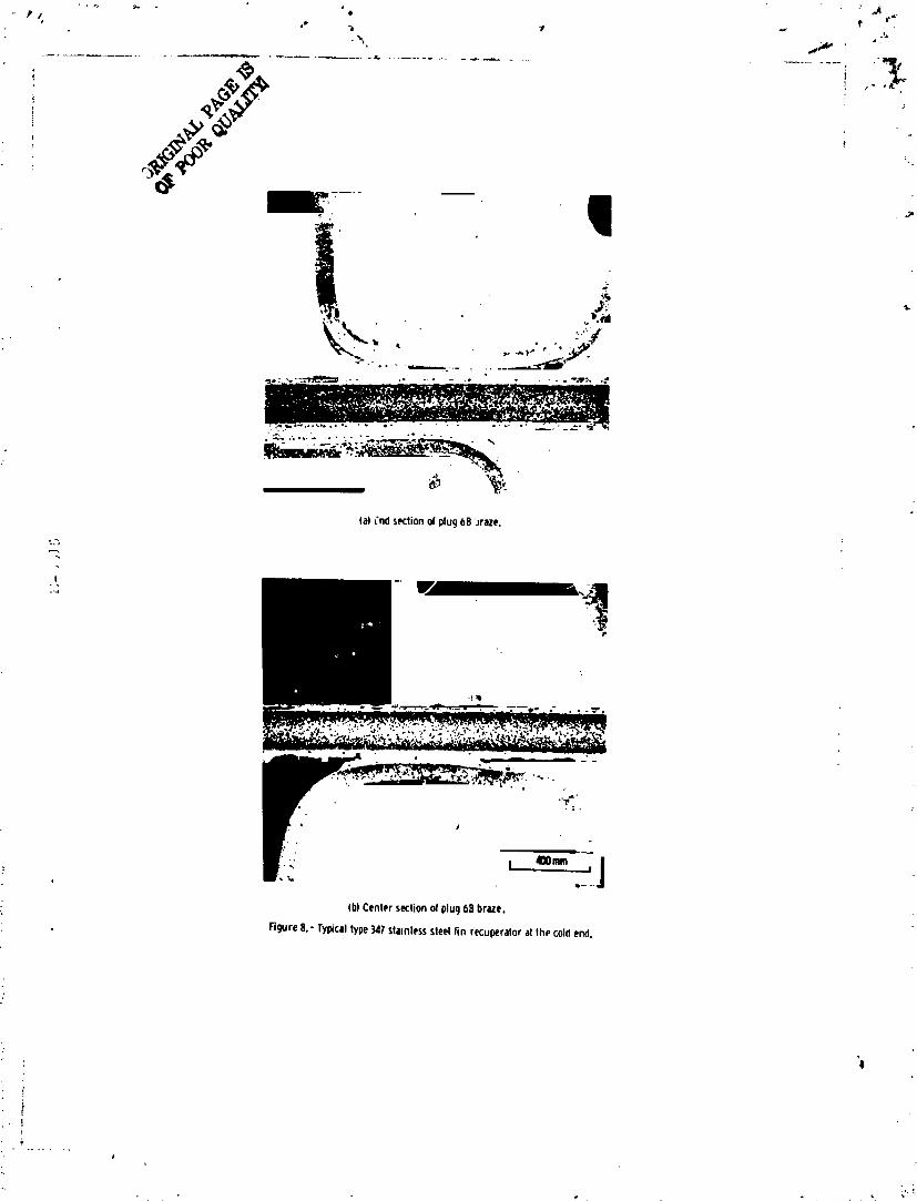
At the cold end of the recuperator, the brazed joints were of good quality withno evidence of deterioration. The microstructure shown in hgure 8 for plug 6B alsois typical for the other cold end locations (plugs 6A and 6C, fig. 3_O))v
Typical hot end braze cracks at a plate-bar Joint (fig. 5(b)) are s}_wn in figure9(a). A gas/nngsten arc repair weld of an earlier crack of this typfj _ shown infigure 9(b). Although the weld repair technique appears to be successful in this case,it did not prove to be a viable solution to the leakage problem in the recuperator.A further attempt to alleviate this leak problem at the plate-bar braze Joints involvedgas hmgsten arc welding a 1. 5-mm-thick stainless-steel cover sheet over the sides
" of {I_ recuper:_)r as shown in figure 3(a). This permitted cont/nuktio_ of the long-term sys_..-_s test with minimum interruptitm.
L f
XXXXXX-O04

Stainless Steel Ducting
Sections were oaken from the type 347 s_.ainleas-steel ducting at the hot end _fthe recuperator at the locations shown in figures 3('o) and 10 using electrodiscbazgemachining (EDM) techniques. Sections 1_ol and 1A-2 from the inlet ducting wereexamined and were found to be sound. Howe_,er, the microstructare of section I,_-2(fig. ll(a)) shows a minor scallop oxidation pa_ern at the inside surface of the weld.
. . Section IB at the ca_tlet ducting was also free of P.aws except for one slightly oxidizedarea at the inside surface (fig. U(b)). Additional sections were taken further down-stream in the outlet ductlng (see figs, 3 and 12). Although the welds and base metalwere sound (sections 1F, 1G, and 1H), localized minor oxidation was observed on theinside surfaces of the welds and base metal (fig. 13). In all of these areas in the duct-ing the oxidation is considered of minor significance because the affected area is asmall percentage of the wall thickness.
Bend test specimens were taken from the IoLation shown in figure 12. Duplicatespecimens 9.04 by 16 by 57 mm were successfully bent about 60o at room tempera-
tare in a guided bend test over a 2t radius with the inside surface of the ductlngloaded in tension. These specimens were then further bent to 130 ° in a vise, There _.
was no evidence of cracking. These results show that the inherent good ductility ofthe type 347 st/tinless steel ducting at the hot end of the recuperator was re_ued.
At the cold end of the recuperater (figs. 3 and 14) the weld in the type 347stainless steel ductlng was sound. There was no evidence of oxidation at the insidesurfaces in this area (fig. 15).
Bend test specimens were obtained near the location from which the metallo-* graphic specime_ was taken (fig. 14). Duplicate specimens, I. 27 by 14 by 54 mm
i with the imzer ducting surface in tension, passed a 60° guided bend test over a 2tradius at room temperature. The specimens were then bent 180° in a vise with noevidence of cracking, thereby demonstratiDg thqt the inherent good ductility was re-tained.
Haste]Joy X Ducting
A portiere of the Hastelloy X ducting, which carried the working fluid from theturbine exhaust to the recuperator is shown In figure 16. The double-wall bellowswas made of type 34_' stainless steel. During dismantling of the recuperator, the
-, , Hastelloy X material exhibited brittleness in that it cracked at the base of a knob
; at a fillet weld and separated from the ducting. By using EDM, section IC in flg-ure 17 was obtained without breaking off the small part of the knob that remained
. " attached to the ducking. Figure 18(a) illustrates the incipient toe crack In the duct-tug immediately adjacent to the fillet weld. The typical base-u_etal mlcrostructure
_" Is shown at higher magnification in figure 18(b).". The gas tungsten arc girth weld between the knob and the flange (section 1C-2._. in figure 17) was sound as shown tn figure 19(a). Edgs-flangs weld 1C-3 was also
sound (fig. 19(b)). Tim other gas tungsten arc welds IC4, IE, and IX (fig. 17) were_' ' also free of flaws.
",._ ]
XXXXXX-O05

5
Bend specimens were obtained from the ducting near the location of the knob(fig. 17). "lwo specimens 1.24 by 16 by 55 mm were tested at room temperaturewith the InsiOe surface of the ducting in tension. The first specimen survived a_Ided bend test of 45° over a 4t bend radius. Subsequent free bending of the firstspecimen in a vise resulted in failure at 120 ° of bending. The second specimensurvived a 2t radius guided bend of 60° but failed at 110 ° in the free bend. Two as-received Hastelloy X sheet reference specimens, 1.35 by 15 by 55 ram, were bent in asimilar manner. A full, 180° free bend was achieved for both specimens. Thisshows the inherent excellent ductility of Hastelloy X material in the as-receivedcondition and demonstrated there was a ductility loss due to the ground testing expo-sure.
Stainless/Hastelloy X Bellows
The type 347 stainless steel bellows (shown in figs. 16 and 20) was welded tothe type 347 stainless-steel hot end Inlet ducting shown in figure 3. A section wasremoved by EDM from the Hastelloy X end of the bellows assembly at the location
shown in figure 20. The welding details of this section are shown in the photo-macrograph in figure 21. In fabrication of the double wall bellows, the ends of thestainless-steel bellows were sandwiched between Hastelloy X rings. Resistanceseam welding was us__d ta fusion weld these members together. A gas tungsten arcfillet weld was s_bsequently us_i to join the e/zds Of double wall bellows and the twoHastelloy X rings. Thus, these members were welded at two locations using twodifferent welding processes. Both the resistance and arc welds are sound. Theweld shown on the right in figure 21 is a gas tungsten arc butt joint between the
: HasteUoy X bellows assembly member and the Hastelloy X ducting.
DISCUSSION
The performance of the recuperator In the systems test was generally saris-factorily in that 21 000 hours of ground testing was achieved. Leakage of the pri-mary. worY;:ng fluid, however, occurred at cracked plate-bar braze Joints. Hight_rmal stress due to constraint and differences in material thickness producedthese cracks,
Fabricatic_ techniques used in the construction of this complex heat exchangerwe_$ quite good as indicated by the quality of the flt-up and brazing of the plate-finstructure. Recuperator ducting materials were in good condition after the groundtest, even though some loss in ductility was noted in the Hastelloy X parts. The
" severe oxidation of the type 347 fins appeared unusual. Even though leakage to theatmosphere occurred several times as a result of the cracking problem, the extentof oxidation of the fins appeared severe for an operating temperature of 675 ° C.A cursory study of fin oxidation versus temperature was undertaken. Segments ofthe recuperator core for these experiments were obtained from the compressorinlet or cold end which had shown no evidence of oxidation in service. Heat treat- '0manta were conducted on these core segments in stagnant air for 100 hours at
!
××××××-006

675 ° C, 800° C, and 1000 ° C. The results are shown metallographlcally in figure 22.
At 675 ° C, oxidation of the stainless steel does not appear to be a problem. At 800 ° C,surface oxidation is evident. In addition, at one location oxidation has proceeded half-
_- way through the wall of the fin, Thus, ff a temperature exposure occurs in the vicinityof 800 ° C for 100 hours in a stagnant air environment, severe oxidation of type 347
i stainless steel can be anticipated, Exposure to 1000 ° C for 100 hours completely de-stroys the thin-wall fins. These results suggest that the recuperator may have experi-
• _i enced higher temperatures than 675 __C.Redesign and fabrication of an improved recuperator for the Brayton system was
undertaken shertly after the leakage problems were noted. The final recuperator de-sign (ref. 4) incorporates a new manifold construction and header bar shapes to alle-viate thermal stress. Double contaminent side plates were used in order to furtherinsure against leaks to the atmosphere. Hastelloy X is specified as the recuperator
• materialbecause of its superior strength and fabricabflity compared with type 347stainless steel. Gold-base brazing filler metal is used throughout the recuperator,
Test results (ref. 4) show that this final design recuperator was operated successfully.It withstood 100 startup and shutdown cycles (inlet temperature, 722 ° C) without develop-ing a fatigue crack that would result in external leakage. Heat transfer performance
with He-Xe working fluid slightly exceeds the requirements, i
SUMMARY OF RESULTS
A type 347 stainless-steel Brayton cycle recuperator and integral stainless-steel: ducting was inspected after 21 000 hours of ground testing. The recuperator operated
at a nominal temperature of 675 ° C at the hot (turbine) end. Hastelloy X elbow ducting _and a stainless-steel/HasteHoy X bellows which saw 11 000 hours of testing were also _:
inspected.1. Workmanship in the recuperator brazement consisting of plate-and-fin core
and the plate-bar sides was very good, Braze cracks, however, occurred at the plate- i
bar Joints apparently because of thermal stresses, i2. Leaks in the Brayton system resulted in air contamination and through-the-wall
oxidation of the 0.10-ram wail stainless-steel fins at the hot end of the recuperator.Temperature excursions above the 675 ° C design temperature may have occurred at !
the hot (turbine) end to produce oxidation of the thin-wall fins,
3, The stainless-steel ducting was still serviceable after the ground test in that ._the the excellent base metal duc_.lllty was retained. All gas tungsten arc weld jointswere sound, i
i 4, No oxidation or other detrimental effects were observed in the ground tested ,.!! stalnless-steel/Hastelloy X bellows.
" 5, A loss of ductility was observed in the HasteUoy X ducting _uring the ground 'test, but service performance was not affected. Gas tungsten arc welds in the_. Hastell._ X ducting were of high quality.
%,
XXXXXX-007

i ii 7 '
REFERENCESj ..
1. Dram, James H. : Inspection of Two Brayton Rotating Units after Extensive
Endurance Testing. NASA TM X-73569, 1976.
2. Macosko, Robert P. ; et al. : A Compact 90-Kilowatt Electric Heat Source for ¢_
Heating Inert Gasses to 1700 ° F. NASA TM X-52778, 1970.
3. Morse, C. J. ;Richard, C. E. ;and Duncan, J. D. : Brayton Heat ExchangerUnit Development Program, Final Report. (AIRESEARCH-71-7450, AfResearchMfg. Co. ; NASA Contract NAS3-10607.) NASA CR-120816, 1971.
4. Kfllackey, J. J. ; Gravest R. ; and Mosinskis, G. : Design and Fabrication of theMinl-Brayton Recuperator (MBR). (AIRESEARCH-78-14972, AiResearch Mfg.Co., NASA Contract NAS3-18029.) NASA CR-189429, 1978.
XXXXXX-O08

8
TABLE 1. - RECUPERATOR OPERATING CONDITIONS AND DESIGN"s
Working fluid (gas).Design .......................... bHe-Xe mixtureFor ground tests ....................... Krypton
Liquid coolant:Type ......................... Dow Coming 200
" Viscosity at 25° C, cS 2Hot gas:
Gas flow rate, kg/sec ...................... 0. 582Inlet temperature, °C ....................... 675Inlet pressure c kPa (absolute) 166, • • • • B • • • • • • • • • • • • •
Cold gas:
Gas flow rate, kg/sec ...................... 0. 576Inlet temperature, °C ....................... 140Inlet pressure, c kPa (absolute) .................. 297
Counterflow section:
Flow length, nun ......................... 500Flow width, mm ......................... 215
Hot-gas fins:Height, mm ............................ 3.9Fins per 2.54 cm (per inch) ..................... 16Thiclmess, mm .......................... 0.10
Type ........................ Offset rectangularCold-ga_ fins:
Height, mm ............................ 3.2Fins per 2,54 cm .......................... 16Thickness, mm .......................... 0.10
i rectangular:_ i Type ........................ OffsetJ Nominal plate thickness, mm .................... 0. 20 :i Number of sandwiches, each side .................. 66
Stack height, mm 503
Side plate thickness, mm ...................... 1.52
aRef. 3•• bMolecular weight, 83.8.
CStructurally, the recuperator hot side is designed to withstand210 kPa (absolute) and the cold side 386 kPa (absolute)•
!
XXXXXX-O09

.;J
i "t I
r'_ ,r BreytonrotatingunitI_l I_Jl s $
,i: Ineat J Alternator'_ 1_' I I [I
i-l-- - _ I ! exchangerL__ _.J unit
Figure1. - SchematicofBraytonpowerconversionsystem.
(:oldgasin_" Crossflowendsections
, Hot_ga_n/_/j Cou'; eri,t fowco_ei i i J i |
i - • J lJ
Coldgasout Ho!gasout
Figure2. - Rccuperat_rschematic.
/ t
t' !
J
:!• t
1}
; .
i e ,
,\.
! 1
o "
XXXXXX-O ] 0

,y,III
Coldend . _Fromturbine
• (low'pressure)
To,_teh.tj (h,_ _"_,.,_.- _/j_.wchanger :rumcompressor• pressure)_l_ __
(hlghpr_sure) "" o_C-76-1268
(a)(;asflowpattern,whitelinesindicatesectioningIoc_,tions.
\
Hotend
_'_E_. _"*- " Cold'end
1 :
2"
(b)LocationsofplugremovalfromthecoreandsectionstakenthroughweldjointsInthedoctlng.
-.- Figure3.- Type_41stainlesssteelrecuperatorassembly.
y _
XXXXXX-O'I "1

I "P "a "/ _ r
. ._
"%
\
o" ;o
_ ,-? _ _ i_!=ilC.76-3_2
Figure4. - sectionrecupergorcorewithplt'gsremoved.
Sawcut(back)surface- -_ Cutoffwheelsurfaces
formetallography
EJ:t_ndJSC_:rg_ "__
_ _._' ,..
' Section484 Section6B7
(a)Centralportionolplug _))Endsectionofplugsh_wlngsh'_wln9plate/fincon- platt#t)arconstrucU,_nit thestrvctlon, outersurface.
/_ Figure5. - Brayedtype347stainlesssteelrecuperatorcorecondructlon.
XXXXXX-O 12

r
(b) Severelin oxidationatcenter sectionot pluq _A.
Figure6. - Typicaloxidationofbrazedtype347stainlesssteelplate/finrecuper_tornearhot en_.
't
XXXXXX-O 13

#
(a) Endsectionofplug4B_)raze.
". _ _ _0 _ N
(b)Centersectionofplug4Bbraze,
"igure7o- lypical plate/ fin type347stainlesssteelrecuperatorjointsmidwaybetweenhot andcoldends.
XXXXXX-014
i
e N:,
(a)ind sectionolplugOB'Jraze.
"3
I
Ib)Centersectionofplug6Sbraze.
Figure8.- Ty_caltype347stainlesssteel/inrecuperatoratthecoldend.
f
h
XXXXXX-O 15

) (btGastungstenarcweldrepairofbrazecrack,pluc/2A.
Figure9.- 8razecra_kinqandweldrepairareasin type347stainlesssteelplate/barjoints.
+
. v,
XXXXXX-O 6

'* //, r •
I
Inlettfro_ _urblnel Outlet
_"
\
¢ ,.¢.,._.•
Figure10. - Cutout locationsin type347stainlesssteel_uctlncjat thehotendof therecuperator.
_: '4I
i
XXXXXX-O17

I_ ,_,,,'lion]A-Zshowir_minorweldoxidation,hotqasinletfromturbine.
..,e
(b)SectionlB_ t_edad9esoutlet.
Figure11,* GastungstenarcweMjointsin type_7stiinl_,sssteelductingethotendOftherecuperetor. '4i
xxxxxx-o

Figure12.- Locationsofcutoutsandbendspecimensin type347stainlesssteel
outletducUngathotendofrecuperator.
'!
4
XXXXXX-O'I 9

¢ri:_re13.- (':'astunqstenarcw_Klr,,type347stainlessst_l dt thehot Pndofthe recuperator, , ,
!
• , _ (_ s_'
xxxXXX-O:

7A
' 10
,. P.4
!
i_'_ Bend ,.specimens_
Figure]4. oCutoutandbondspecimenlocationsin type347stainlesssteelductingatcoldendoftherecuperator.
't
XXXXXX-021

t
Fiqure 15.- Typicalsoundweldin type347 stainless steelducting at section la. coldend. i,,
2
Separation-_
f
I '
¢-;Pl_ee
Figure 16,- hastelloyX elbow! type347stainlesssteeldouble-wailbellows, assembly. 'i'
XXXXXX-022

i i i
• "° lC-4' Longseam \(humpon|D)
,
Longsmm
j SeparationJ I_r: _'_ _ Bend
i specimens
Figure17.- PortionofHastelloyX elbowclosesttoturbineexhaustshowinglocationsofcutoutsectionsandbendspecimens.
° ................
.... XXXXXX-023

¢
I
\ -
o
• £
,,_ A 'xu, ),-
i '(a) Incipient toecrackin sectionlC - 1 at outersurf;,ce.
I z
: I _ 100mm ,.,
_b)Typicalbasemetal mlcrostru_uro from sectionIC-2.
Figure IlL- Incl_t crick n_r HestolloyX gastungstenere:_ fillet-mid andHastelloyX Nse metalmicrostouctureethigher
magnification. '41
,,"
XXXXXX-024


Figure20. - CutoutlocationatjunctionofHastelloyXelW>wrndtype347stalnles_steelbellows.
'#
,\.
XXXXXX-026

: I ilO0mll I%
; i 1#-19Cemplel#illll el the ftns Ifler iGOhours it iODO¢. 'l
" i Rture _,- Ollitltion effecton_reze_b#le347stlnlesi rail "
i ricullrilor coreduefo 100hours itlinlnt ilr exloiure it; 675C._00Cln(I1000C, ,,'
t, i
XXXXXX-027