- wiring brochure w 033 - amazon s3 · 3 wiring brochure wiring and ... relay for product...
TRANSCRIPT

1 of 8 © 2007 W 033 - 10/07
W 03310/07tekmarNet®4 Timer 033
- Wiring Brochure
Overview
Information Brochure
Choose controlsto match
application
1 Application BrochureDesign your mechanical applications
2 LayoutBrochureRough-in
wiring instructions
3 WiringBrochureWiring and
installation of specific control
4 JobRecord
Record settings & wiring details for future reference
6DataBrochure
Control settings and sequence of
operation
5
The following brochure describes how to wire the tekmarNet®4 (tN4) Timer 033. The 033 has one dry relay contact that opens or closes based on the programmable schedule. The relay can be connected to the UnOccupied switch input on a tekmar control or to other third party equipment. The 033 uses communication to indicate the schedule to a tN4 system.
Table of Contents:
Definitions .......................................................................2Rough-In Wiring .............................................................2Remove the Wiring Cover ..............................................3Mounting the Timer ........................................................3Wiring Symbols ...............................................................3
Electrical Drawings ......................................................3-4Wiring the Timer .............................................................5Troubleshooting the Wiring .............................................6
Testing the Wiring ...........................................................6
Technical Data ................................................................8
1tN4
tN4 Timer 033
033
Made inCanada
Mmm YYYYLot #
Meets Class B:Canadian ICESFCC Part 15
Power: 24 V ±10% 50/60 Hz 2.7 VARelay: 24 V (ac) 2 A
1011-03
RC 2
3 54Relay
For product instructions see brochureUse at least 194°F (90°C) conductors
12
3
Switch Settings:
Relay NC4 Schedules
ON
1 ScheduleRelay NO
Relay
DIPSwitches
tN4Network
24 V (ac) Power
© 2007 W 033 - 10/07 2 of 8
Relay2 Cond. / 18 AWG ComUnO Sw
3 Cond. / 18 AWG
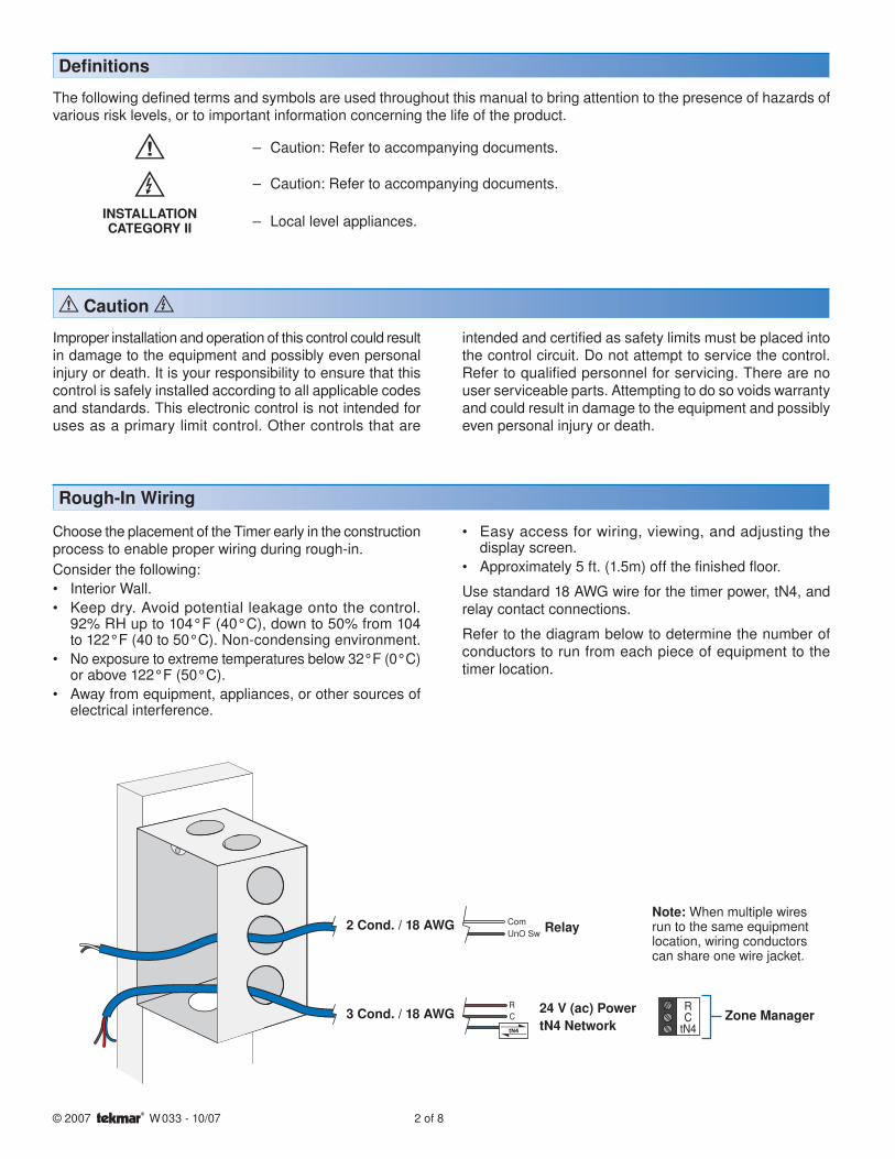
Note: When multiple wiresrun to the same equipmentlocation, wiring conductorscan share one wire jacket.
24 V (ac) PowertN4 Network
Zone Manager
Defi nitions
The following defined terms and symbols are used throughout this manual to bring attention to the presence of hazards of various risk levels, or to important information concerning the life of the product.
– Caution: Refer to accompanying documents.
– Caution: Refer to accompanying documents.
INSTALLATIONCATEGORY II – Local level appliances.
Caution
Improper installation and operation of this control could result in damage to the equipment and possibly even personal injury or death. It is your responsibility to ensure that this control is safely installed according to all applicable codes and standards. This electronic control is not intended for uses as a primary limit control. Other controls that are
Choose the placement of the Timer early in the construction process to enable proper wiring during rough-in.Consider the following:
Interior Wall.Keep dry. Avoid potential leakage onto the control.92% RH up to 104°F (40°C), down to 50% from 104 to 122°F (40 to 50°C). Non-condensing environment.No exposure to extreme temperatures below 32°F (0°C) or above 122°F (50°C).Away from equipment, appliances, or other sources of electrical interference.
••
•
•
Rough-In Wiring
Easy access for wiring, viewing, and adjusting the display screen.Approximately 5 ft. (1.5m) off the finished floor.
Use standard 18 AWG wire for the timer power, tN4, and relay contact connections.
Refer to the diagram below to determine the number of conductors to run from each piece of equipment to the timer location.
•
•
intended and certified as safety limits must be placed into the control circuit. Do not attempt to service the control. Refer to qualified personnel for servicing. There are no user serviceable parts. Attempting to do so voids warranty and could result in damage to the equipment and possibly even personal injury or death.

3 of 8 © 2007 W 033 - 10/07
Mounting the Timer
If a single gang switch box is used, an Adaptor Plate 007 is required to mount the Timer to the box.
Fasten the base of the Timer to the adaptor plate.Feed the wiring through the openings in the back of the adaptor plate and Timer.Use the upper and lower screw holes to fasten the adaptor plate to the box.
••
•
Remove the Wiring Cover:
To remove the wiring cover:Place a small slot screwdriver or similar tool into the slot located on the top of the Timer.While pushing against the plastic tab, pull the top of the front cover so that it pivots around the bottom edge of the Timer’s base.
•
•
The electrical drawing examples on the following pages show the 033 in common applications. Choose the drawing that most accurately depicts the components in your system and use that drawing as a guide to aid in wiring your system.
These are only concept drawings, not engineered drawings. They are not intended to describe a complete system nor any particular system. It is up to the system
Electrical Drawings
Wiring Symbols
Dry contact switch. Operates a device. tekmarNet®4
If a switch box was not used, mount the Timer directly to the wall.
Feed the wiring through the openings in the back of the Timer.Use screws in the screw holes to fasten the Timer to the wall. At least one of the screws should enter a wall stud or similar rigid material.
•
•
designer to determine the necessary components for and configuration of the particular system being designed including additional equipment isolation relays (for loads greater than the controls specified output ratings) and any safety devices which in the judgement of the designer are appropriate in order to properly size, configure and design that system and to ensure compliance with building and safety code requirements.
OR
Stud
SwitchBox
TimerBase
007 AdaptorPlate
Timer3 1/4”
(83 mm)
Stud
23/8” (60 mm)
screwhole
23/8” (60 mm)
screwhole
Timer
TimerBase
Wall
Mounted on wallboardMounted on switch box
Menu Item
Remove coverPush tab1
2

© 2007 W 033 - 10/07 4 of 8
Electrical Application 033 E1
Description:Provides up to 4 programmable setback schedules for a single tekmarNet®4 system.
1tN4
tN4 Timer 033
033
Made inCanada
Mmm YYYYLot #
Meets Class B:Canadian ICESFCC Part 15
Power: 24 V ±10% 50/60 Hz 2.7 VARelay: 24 V (ac) 2 A
1011-03
RC 2
3 54Relay
For product instructions see brochureUse at least 194°F (90°C) conductors
12
3
Switch Settings:
Relay NC4 Schedules
ON
1 ScheduleRelay NO
033
tN4 C R
Zone Manager
Electrical Application 033 E2
Description:Provides a single setback schedule for a tekmar stand alone control system.
1tN4
tN4 Timer 033
033
Made inCanada
Mmm YYYYLot #
Meets Class B:Canadian ICESFCC Part 15
1011-03
RC 2
3 54Relay
For product instructions see brochureUse at least 194°F (90°C) conductors
12
3
Switch Settings:
Relay NC4 Schedules
ON
1 ScheduleRelay NO
033
Com
UnOSw
UnOccupiedSwitch Input
RC
External Class 2Transformer
24 V (ac)
Power: 24 V ±10% 50/60 Hz 2.7 VARelay: 24 V (ac) 2 A

5 of 8 © 2007 W 033 - 10/07
For non-tN4 systems the tN4 terminal can be left empty. On tN4 systems wire the tN4 communication to terminals tN4 and C.
If a Zone Manager is used:Connect the tN4 on the Timer to any available tN4 on the Zone Manager. Connect the C on the Timer to any available C on the Zone Manager.
Note: This does not need to be repeated if the Timer is powered by the Zone Manager, as long as the tN4, C, and R have all been connected to the same zone, or the same bus.
•
•
tN4 Communication Terminals 1, 2
On tN4 systems, Relay 1 is not required and the terminals can be left empty.
On non-tN4 systems, wire the relay contact to the switch terminals on the control system that will cause the control system to change status (ie. go from Occupied to Unoccupied).
Use these terminals as a switch to operate the setback schedule for the control system.
•
Relay Terminals 4, 5
Wire 24 V (ac) to terminals C and R.
If a Zone Manager is used:Connect C on the Timer to any available C on the Zone Manager. Connect R on the Timer to any available R on the Zone Manager.
If a 24 V (ac) transformer is used: Connect C on the Timer to C on the transformer. Connect R on the Timer to R on the transformer.
•
•
••
Power (24 V (ac)) Terminals 2, 3
Wiring the Timer:
If a Zone Manager is not used:Connect the tN4 on the timer to the tN4 on another tN4 device on the network.Connect the C on the Timer to the C terminal on another tN4 device on the same tN4 bus that the Timer’s tN4 wire is terminated on.
•
•
TimerZone Manager
or 24 V (ac) Transformer
C R2 3
Timer
tN4 Thermostat or Control
tN4 C1 2
Control with UnOccupied
Switch
Timer
Relay4 5
Com UnOSw
C R
tN4 C

© 2007 W 033 - 10/07 6 of 8
Troubleshooting the Wiring
The following tests are to be performed using standard testing practices and procedures and should only be carried out by properly trained and experienced persons.
A good quality electrical test meter, capable of reading from at least 0-300 V (ac), 0-2,000,000 Ohms, and testing for continuity is essential to properly test the wiring.
General
Testing the Wiring
Testing 24 V (ac) Power Supply
1. Remove the front cover from the Timer.2. Use an electrical test meter to measure (ac) voltage between the R and C terminals. The reading should be
24 V (ac) +/– 10%.3. Install the front cover.
1. Navigate to the schedule menu that the Relay uses. (Schedule 1 to 4)
2. Remove the front cover from the Timer.3. Disconnect the wires from the relay contact.4. Use an electrical test meter and check for continuity
across the relay.If Switch 3 is set to NO, the Sleep or UnOcc segments will display when continuity is present.If Switch 3 is set to NC, the Wake or Occ segments will display when continuity is present.
5. Reconnect the wires to the relay.6. Install the front cover on the Timer.
•
•
033 LCD Display Segments
Display changes depending on Switch 3 setting.
Testing the Relay Contact
C R2 3
###

7 of 8 © 2007 W 033 - 10/07
The symbol is shown on the display when communication is present. If the timer is connected in a network and the communication is missing, there may be an open or short circuit on the tN4 and C bus wires.1. Remove the front cover from the thermostat.2. Test the wiring for short circuits:
a. Disconnect the tN4 bus wires on one end.b. Install wire nuts on each wire to ensure the wire ends
are not touching.c. Disconnect the tN4 bus wires on the other end.d. Measure for continuity using an electrical meter.e. If continuity is present, there is a short circuit fault
along the wires. It is recommended to replace the tN4 bus wires.
Testing the tN4 Network
3. To test for open circuits:a. Disconnect the tN4 bus wires on one end and connect
them together.b. Disconnect the tN4 bus wires on the other end.c. Use an electrical meter to measure for continuity.d. If there is no continuity, there is an open circuit fault
along the wires. It is recommended to replace the tN4 bus wires.

tekmar Control Systems Ltd., Canadatekmar Control Systems, Inc., U.S.A.Head Office: 5100 Silver Star RoadVernon, B.C. Canada V1B 3K4(250) 545-7749 Fax. (250) 545-0650Web Site: www.tekmarcontrols.com
Product design, software and literature are Copyright © 2007 by:tekmar Control Systems Ltd. and tekmar Control Systems, Inc. 8 of 8 All specifications are subject to change without notice.
Printed in Canada. W 033 - 10/07.
Technical Data:
tekmarNet®4 Timer 033
Control Microprocessor PID control; This is not a safety (limit) control
Packaged weight 0.46 lb. (210 g)
Enclosure J, white PVC plastic
Dimensions 2-7/8” H x 2-7/8” W x 13/16” D (73 x 73 x 21 mm)
Approvals CSA C US, CSA/UL 61010-1, meets Class B: ICES and FCC Part 15
Ambient conditions Indoor use only, 32 to 122°F (0 to 50°C)
92% RH up to 104°F (40°C), 50% RH if > 104°F (40°C)
Altitude <9840 feet (3000 m), Installation Category II, Pollution Category 2
Power supply 24 V (ac) ± 10% 50/60 Hz, 2.7 VA, NEC / CEC Class 2
Relay 24 V (ac) 2 A
Technical Data
The installer must ensure that this control and its wiring are isolated and / or shielded from strong sources of electromag-netic noise. Conversely, this Class B digital apparatus complies with Part 15 of the FCC Rules and meets all requirements of the Canadian Interference-Causing Equipment Regulations. However, if this control does cause harmful interference to radio or television reception, which is determined by turning the control off and on, the user is encouraged to try to correct the interference by re-orientating or relocating the receiving antenna, relocating the receiver with respect to this control, and / or connecting the control to a different circuit from that to which the receiver is connected.
Cet appareil numérique de la classe B respecte toutes les exigences du Règlement sur le matériel brouilleur du Canada.