datatools.tamscenter.com · web viewthis guide applies to newly received monitoring equipment with...
TRANSCRIPT

Instrument Acceptance Testing, Setup & Operating Parameters, and Designations Guide
SOP Reference
Revision Number 1
09/22/15
Instrument Acceptance Testing, Setup & Operating Parameters and Designations Guide Rev. 1
Table of Contents
Monitoring Instruments’ Acceptance Testing Process Guide.............................................3General Information..................................................................................................................................3
Instrument Setup.......................................................................................................................................4
Administrative.........................................................................................................................................15
Instrument Designations..........................................................................................................................17
Monitoring Instruments’ Acceptance Testing Process Guide
This guide applies to newly received Monitoring Equipment with a value of $5000 or more.
General Information
1. Check for shipping damage. If there is damage, work with the Senior Office Specialist to notify the vendor for repair or replacement.
2. Conduct an inventory of the shipment to ensure the instrument and all accessories were received. If there are items missing, work with the Senior Office Specialist to notify the vendor and obtain missing equipment.
3. Once all the parts/items are received, check off each item on the packing slip, initial and date. Provide packing slip to the supervisor for processing.
4. Work with Monitoring’s Senior Office Specialist to obtain Clark County asset tags. Complete the Asset Description, Manufacturer, Serial Number, Vendor Name, Warranty Expiration Date, Purchase Date, Purchase Order #, Model, Estimated Life in Years and Purchase Cost on the Property Input Form located at: P:\Air Monitoring\Admin\Inventory & Disposal\Forms\Property Input Form (Use every time).docx. Submit the paperwork via email or hard copy to the Senior Office Specialist. The Senior Office Specialist will ensure the County inventory and DAQ Equipment Inventory is updated and will issue the asset tags to the Technician.
5. For instruments that have certifications, provide a copy of each certificate to the Senior Office Specialist so the certificates can be placed on the P drive.
6. Create the instrument log and fill out the appropriate information in the header and body of the document. The logbook template is located at: P:\Air Monitoring\Instrumentation \Logs. Indicate information related to shipping damage, performance of QC checks,
9/22/15 Page 2 of 21

Instrument Acceptance Testing, Setup & Operating Parameters and Designations Guide Rev. 1
standard operational settings, Clark County asset tag number, serial number, vendor name, make, model, PO #, purchase date and other relevant information.
7. Complete the appropriate acceptance form at: P:\Air Monitoring\Instrumentation\ Acceptance Tests . If the form does not exist, inform supervisor, create the form, complete the form and post it. Ensure the instrument’s standard operational settings are documented in the form and instrument log.
8. Complete all QC checks. For example, on gas instruments, verify and adjust (if necessary) zero and span points. On PM instruments, verify and adjust (if necessary) flow, temperature, pressure, and leak (where appropriate). Externalize in-line particulate filter. Ensure all operational settings are within tolerance.
9/22/15 Page 3 of 21

Instrument Acceptance Testing, Setup & Operating Parameters and Designations Guide Rev. 1
Instrument Setup
NOTE: DEPENDING ON INSTRUMENT OPTIONS AND CONFIGURATIONS, NOT ALL TEST PARAMETERS WILL BE AVAILABLE IN THE INSTRUMENTS
a. TAPI 200 Series Nitrogen Oxides Analyzer i. See the manufacturer’s manual on how to perform a Pneumatic Leak
Checkii. See the manufacturer’s manual on how to perform a Sample Flow Check
iii. See the manufacturer’s manual on how to set the analog output to 0 – 1 VDC (all 3 channels)
iv. See the manufacturer’s manual on how to set the scale 0 – 500 ppb (all 3 channels). Note: the NOy analyzer is set to 0 – 200 ppb
Verify Instrument specifications match values in table below. If not, see instrument manual or TAPI Technical Support of corrective action.
PARAMETER RECORDED VALUE ACCEPTABLE VALUERANGE PPB/PPM 50 PPB TO 20 PPM
NOx STAB PPB/PPM ≤ 1 PPB WITH ZERO AIRSAMPLE FLOW CM3 500 ± 50OZONE FLOW CM3 80 ± 15
PMT SIGNAL WITH ZERO AIR
MV -20 TO 150
PMT SIGNAL AT SPAN GAS CONC
MV PPB
0-5000MV0-20,000 PPB
NORM PMT SIGNAL AT SPAN GAS CONC
MV PPB
0-5000MV0-20000PPB
AZERO MV -20 TO 150HVPS V 400 – 900
RCELL TEMP ºC 50 ± 1BOX TEMP ºC AMBIENT ± 5ºCPMT TEMP ºC 7 ± 2ºC
MOLY TEMP ºC 315 ± 5ºCRCEL PRESS IN-HG-A <10SAMP PRESS IN-HG-A AMBIENT ± 1NOx SLOPE 1.0 ± 0.3
NOx OFFSET 50 To 150NO SLOPE 1.0 ± 0.3
NO OFFSET 50 To 150ETEST PMT MV 2000 ± 1000OTEST PMT MV 2000 ± 1000
Values are in the Signal I/OREF_4096_MV MV 4096mv ±2mv and Must be
StableREF_GND MV 0± 0.5 and Must be Stable
9/22/15 Page 4 of 21

Instrument Acceptance Testing, Setup & Operating Parameters and Designations Guide Rev. 1
b. TAPI 300 Series Carbon Monoxide Analyzeri. See the manufacturer’s manual on how to perform a Pneumatic Leak
Checkii. See the manufacturer’s manual on how to perform a Sample Flow Check
iii. See the manufacturer’s manual on how to set the analog output to 0 – 1 VDC
iv. See the manufacturer’s manual on how to set the scale 0 – 50 ppm v. See the manufacturer’s manual on how to setup Auto-Zero; Note: the
instrument’s Amber light will remain on
Verify Instrument specifications match values in table below. If not, see instrument manual or TAPI Technical Support of corrective action.
PARAMETER DISPLAYED AS UNITS NOMINAL RANGE
Range RangePPM, MGM1,2
PPB, UGM11 – 1000 PPM1
5 – 5000 PPM2
Stability STABIL PPM<1.0 PPM
with Zero Air
CO Measure CO MEAS mV 2500 – 4800 MV
CO Reference CO REF mV 2500 – 4800MV
Measure/Reference Ratio MR RATIO – 1.1 – 1.3 W/ Zero Air
Pressure PRES In-Hg-A -2”Ambient Absolute
Sample Flow SAMP FL cm3/min 800 ± 10%
Sample Temp SAMPLE TEMP °C 48 ± 4
Bench Temp BENCH TEMP °C 48 ± 2
Wheel Temp WHEEL TEMP °C 68 ± 2
Box Temp BOX TEMP °C Ambient + 7 ± 10
Photo Drive PHT DRIVE mV 250 mV – 4750 mV
Slope of CO Measurement CO SLOPE – 1.0 ± .3
Offset of CO Measurement CO OFFSET PPM 0 ± 0.3
Dark Cal Reference signal REF DARK OFFSET mV 125 ± 50 mV
Dark Cal Measurement Signal MEAS DARK OFFSET mV 125 ± 50 mV
Electric Test PPM 40 ± 2 PPM1T300, M300E, 2T300M, M300EM
9/22/15 Page 5 of 21

Instrument Acceptance Testing, Setup & Operating Parameters and Designations Guide Rev. 1
c. TAPI 400 Series Ozone Analyzeri. See the manufacturer’s manual on how to perform a Pneumatic Leak
Checkii. See the manufacturer’s manual on how to perform a Sample Flow Check
iii. See the manufacturer’s manual on how to set the analog output to 0 – 1 VDC
iv. See the manufacturer’s manual on how to set the scale 0 – 500 ppb
Verify Instrument specifications match values in table below. If not, see instrument manual or TAPI Technical Support of corrective action.
PARAMETER RECORDED VALUE ACCEPTABLE VALUERANGE PPB/PPM 1 – 10,000 PPB
STABIL <= 1.0 PPB WITH ZERO AIR
O3 MEAS mV 2500 – 4800 mV
O3 REF mV 2500 – 4800 mV
O3 GEN1 mV 80 mV. – 5000 mV.
O3 DRIVE1 mV 0 – 5000 mV.
PRES IN-HG-A ~ - 2”AMBIENT ABSOLUTE
SAMPLE FL CM3/MIN 800 ± 10%
SAMPLE TEMP ºC 10 – 50 ºC
PHOTO LAMP ºC 58 ºC ± 1 ºC
O3 GEN TMP1 ºC 48 ºC ± 3 ºC
BOX TEMP ºC 10 – 50 ºC
SLOPE 1.0 ± .15
OFFSET PPB 0.0 ± 5.0 PPB
FOLLOWING VALUES ARE UNDER THE SIGNAL I/O SUBMENU
REF_4096_MV mV 4096 mv ± 2mv and Must be Stable
REF_GND mV 0 ± 0.5 and Must be Stable1 If IZS valve option installed.
d. TAPI 100 Series Sulfur Dioxide Analyzeri. See the manufacturer’s manual on how to perform a Pneumatic Leak
Checkii. See the manufacturer’s manual on how to perform a Sample Flow Check
iii. See the manufacturer’s manual on how to set the analog output to 0 – 1 VDC
iv. See the manufacturer’s manual on how to set the scale 0 – 100 ppb
9/22/15 Page 6 of 21

Instrument Acceptance Testing, Setup & Operating Parameters and Designations Guide Rev. 1
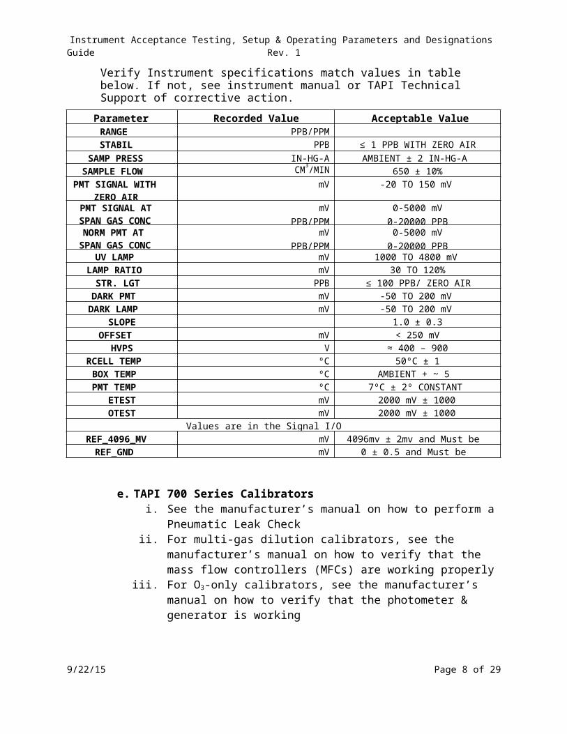
Verify Instrument specifications match values in table below. If not, see instrument manual or TAPI Technical Support of corrective action.
Parameter Recorded Value Acceptable ValueRANGE PPB/PPMSTABIL PPB ≤ 1 PPB WITH ZERO AIR
SAMP PRESS IN-HG-A AMBIENT ± 2 IN-HG-ASAMPLE FLOW CM3/MIN 650 ± 10%
PMT SIGNAL WITH ZERO AIR
mV -20 TO 150 mV
PMT SIGNAL AT SPAN GAS CONC
mV PPB/PPM
0-5000 mV0-20000 PPB
NORM PMT AT SPAN GAS CONC
mV PPB/PPM
0-5000 mV0-20000 PPB
UV LAMP mV 1000 TO 4800 mVLAMP RATIO mV 30 TO 120%
STR. LGT PPB ≤ 100 PPB/ ZERO AIRDARK PMT mV -50 TO 200 mV
DARK LAMP mV -50 TO 200 mVSLOPE 1.0 ± 0.3
OFFSET mV < 250 mVHVPS V ≈ 400 – 900
RCELL TEMP ºC 50ºC ± 1BOX TEMP ºC AMBIENT + ~ 5PMT TEMP ºC 7ºC ± 2º CONSTANT
ETEST mV 2000 mV ± 1000OTEST mV 2000 mV ± 1000
Values are in the Signal I/OREF_4096_MV mV 4096mv ± 2mv and Must be Stable
REF_GND mV 0 ± 0.5 and Must be Stable
e. TAPI 700 Series Calibratorsi. See the manufacturer’s manual on how to perform a Pneumatic Leak
Checkii. For multi-gas dilution calibrators, see the manufacturer’s manual on how
to verify that the mass flow controllers (MFCs) are working properly iii. For O3-only calibrators, see the manufacturer’s manual on how to verify
that the photometer & generator is working
Verify Instrument specifications match values in table below. If not, see instrument manual or TAPI Technical Support of corrective action.
9/22/15 Page 7 of 21
Instrument Acceptance Testing, Setup & Operating Parameters and Designations Guide Rev. 1
Multi-Gas PARAMETER UNITS NOMINAL RANGE
ACT CAL LPM TARG ± 2%TARG CAL LPM 0.001 - 0.100ACT DIL LPM TARG ± 2%TARG DIL LPM 0.010 - 1003 Gen Ref mV 100 - 500003 Flow CC/MIN 100 ± 2503 Gen Drive mV 0 - 500003 Lamp Temp Deg. C 48 ± 1CAL Press In-Hg-A 25 - 30DIL Press In-Hg-A 25 - 30REG Press In-Hg-A 20 ± 1ACT PPB/PPM TARG ± 2%TARG PPB/PPM Requested Conc.Box Temp Deg. C Amb ± 3PERM Temp Deg. C 50.0 ± 1PERM Flow CC/MIN 100 ± 25Photo Meas mV 2500 - 4800Photo Ref mV 2500 - 4800Photo Flow LPM 0.8 ± 0.08Photo Lamp Deg. C 52 ± 1Phot Spress In-Hg-A Amb ± 1Phot Stemp Deg. C Amb ± 3Phot Slope 0.85 - 1.5Phot Offs ± 10DCPS mV 2500 ± 200
O3-Only Parameter Units Normal Range
TIME HH:MM:SS:DCPS MV 2500 ± 200BOX TEMP DEG C 10-50°cO3 OFFSET PPB 0 ± 10O3 SLOPE - 1 ± .15REG PRESSURE IN-HG-A 20 ± 2O3 GEN TMP DEG C 48 ± 3O3 GEN FLOW L/MIN 1-5LPMANA LAMP TMP DEG C 52 ± 3SAMPLE TEMP DEG C 10 –50SAMPLE FLOW SCC/MIN 800 ±10%SAMPLE PRESS IN-HG-A -2” ambient absoluteO3 DRIVE MV 0-5000O3 GEN REF MV 0-5000O3 REF MV 2500-4800O3 MEAS MV 2500 - 4800 mVO3 SET PPB/PPM 50ppb – 1000ppb
9/22/15 Page 8 of 21

Instrument Acceptance Testing, Setup & Operating Parameters and Designations Guide Rev. 1
f. TAPI 700 Series and Sabio Zero Air Generators (ZAG)i. Ensure the ZAG powers up properly
ii. Conduct a leak check. See the manufacturer’s manual on how to perform a pneumatic leak check
iii. Ensure the ZAG is configured with the proper scrubbers
Inform the Supervisor when the above ZAG checks are done. ZAGs that are designated as standards should be stored in the appropriate standard’s area. For field-going ZAGs, the Supervisor will assign the ZAG to a specific site, and ZAG will then be verified at the site in accordance with the Zero Air Generator Verification Guide and Schedule.
g. Thermo 5014i (Continuous PM 10 or 2.5)i. Ensure the 5014i powers up properly
ii. Determine if the Instrument will be used for PM 10 or PM 2.5iii. Configure the unit as described in the 5014i Acceptance Testing Guideiv. Once located in the field, the unit must have addition setup parameters
checks before it may go into operation.
5014i SETUP GUIDE PM10 PM2.5
Instrument Main MenuRange
CONC Units ug/m3 ug/m3PM Range 1500 ug/m3 (Custom
Range)1000 ug/m3
Integration Time 20 min 20 min
24-Hour AverageStart Time 00:00 00:00
Calibration FactorsPM BKG 0.0 0.0PM COFF 1.0 1.0
Instrument Controls MenuSet Flow Pump
Flow 16.67 16.67Pump On On
Set HeaterControl Set To RH Control RH ControlRH Threshold 35% 35%Temp Threshold 30C° 30C°
9/22/15 Page 9 of 21

Instrument Acceptance Testing, Setup & Operating Parameters and Designations Guide Rev. 1
5014i SETUP GUIDE PM10 PM2.5
Filter Tape ControlMass Limit 1500 ug/m3 1500 ug/m3Start Date Next Day’s Date Next Days’ DateHour 00:00 00:00Set Period 8 Hours 8 Hours
Tape Counter Reset to zero after replacing filter tape
Volumetric Conditions Temperature STD ACTPressure STD ACT
I/O ConfigurationAnalog Output Configuration
Allow Over/Under Range OFF OFFVoltage Control
(1) Select Range 0-5 V 0-5 VSelect Min Value 000.0% 000.0%
I/O ConfigurationAnalog Output Configuration
Select Max Value 100.0% 100.0%
Choose Signal OutputChoose Signal Type Concentration (1) PM (1) PM
(2) Select Range 0-5 V 0-5 VSelect Min Value 003.8% 003.8%Select Max Value 028.8% 028.8%
Choose Signal OutputChoose Signal Type Other Measurements (2) Mass Mass
Select Range 0-5 V 0-5 VSelect Min Value 000.0% 000.0%Select Max Value 100.0% 100.0%
Choose Signal to OutputChoose Signal Type Other Measurements (3) FLOW VOL FLOW VOL
DATE/TIME Today/PST Today/PSTTIMEZONE UTC (GMT) UTC (GMT)
9/22/15 Page 10 of 21

Instrument Acceptance Testing, Setup & Operating Parameters and Designations Guide Rev. 1
5014i SETUP GUIDE PM10 PM2.5Alarms Configuration MenuInstrument Alarms
Filter Tape Counter 450 450Detector Alarms Alpha 0-100 1/s 0-100 1/sDetector Alarms Beta 5000-20000 1/s 5000-20000 1/s
RH/Temperature AlarmsAmbient RH 0% - 95% 0% - 95%Sample RH 0% - 75% 5% - 75%Ambient Temp -30 to 60C° -30 to 60C°Flow Temp 0 to 60C° 0 to 60C°Board Temp 0 to 40C° 0 to 40C°
Pressure/Vacuum AlarmsBaro Press 400-800 mmHg 400-800 mmHgVacuum 0-250 mmHg 0-250 mmHgFlow 0-40 mmHg 0-40 mmHg
Flow AlarmsFlow Actual
Min 16.25 16.25Max 17.09 17.09
Concentration AlarmsAVG PM 0-10000 0-10000INST PM 0-10000 0-10000
Inform the Supervisor when the above 5014i checks are done. 5014i’s that are designated as extras or spares should be stored in the appropriate area. For field-going 5014i’s, the Supervisor will assign the 5014i to a specific site, and 5014i will then be verified at the site in accordance with the Guide and Schedule.
h. MetOne BAM 1020 (Continuous PM 10 or 2.5)i. Ensure the BAM 1020 powers up properly
ii. Determine if the Instrument will be used for PM 10 or PM 2.5iii. Configure the unit as described in the BAM 1020 Acceptance Testing
Guide or manufacturer’s manual.
BAM 1020 Setup GuideAssemble Sampler Determine if unit will collect PM 10 or 2.5. If
setting up for 2.5, the sharp cut cyclone must be in place on the down tube. See Manual
9/22/15 Page 11 of 21

Instrument Acceptance Testing, Setup & Operating Parameters and Designations Guide Rev. 1
If used to determine PM Coarse two units must be setup, 1 for PM10 the other for PM 2.5
Initial Power on Settings Set Sampler Date and Time (PST)Set PM 2.5 to Slave if using CoarseSet up Clock Synchronization (Cable between both samplers)Set Flow Type to ActualSet Concentration Type to ActualIf using a Sutron Datalogger Output Parameters must match unit which is being replaced or currently in operation.
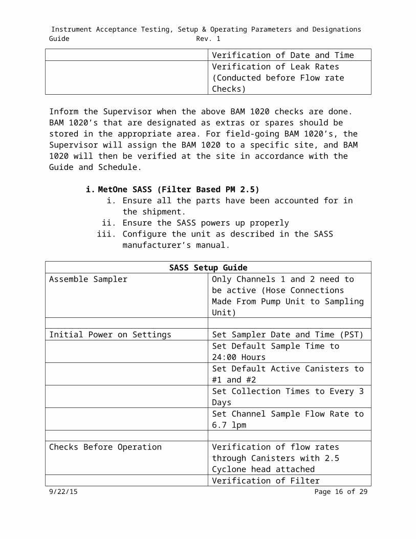
Checks Before Operation Verification of Flow rateVerification of Ambient TemperatureVerification of Barometric PressureVerification of Date and TimeVerification of Leak Rates (Conducted before Flow rate Checks)
Inform the Supervisor when the above BAM 1020 checks are done. BAM 1020’s that are designated as extras or spares should be stored in the appropriate area. For field-going BAM 1020’s, the Supervisor will assign the BAM 1020 to a specific site, and BAM 1020 will then be verified at the site in accordance with the Guide and Schedule.
i. MetOne SASS (Filter Based PM 2.5)i. Ensure all the parts have been accounted for in the shipment.
ii. Ensure the SASS powers up properlyiii. Configure the unit as described in the SASS manufacturer’s manual.
SASS Setup GuideAssemble Sampler Only Channels 1 and 2 need to be active (Hose
Connections Made From Pump Unit to Sampling Unit)
Initial Power on Settings Set Sampler Date and Time (PST)Set Default Sample Time to 24:00 HoursSet Default Active Canisters to #1 and #2Set Collection Times to Every 3 DaysSet Channel Sample Flow Rate to 6.7 lpm
Checks Before Operation Verification of flow rates through Canisters with 2.5 Cyclone head attachedVerification of Filter TemperatureVerification of Ambient Temperature
9/22/15 Page 12 of 21

Instrument Acceptance Testing, Setup & Operating Parameters and Designations Guide Rev. 1
Verification of Barometric PressureVerification of Date and TimeVerification of Leak Rates (Conducted before Flowrate Checks)
Inform the Supervisor when the above SASS checks are done. A SASS that is designated as an extra or spare should be stored in the appropriate area. For field-going SASS, the Supervisor will assign the SASS to a specific site, and SASS will then be verified at the site in accordance with the Guide and Schedule.
j. Thermo 2025i (Filter Based PM 2.5)i. Ensure all the parts have been accounted for in the shipment.
ii. Ensure the 2025i powers up properlyiii. Configure the unit as described in the 2025i Acceptance Testing Guide
and manufacturer’s manual.iv. Once located in the field, the unit must have addition setup parameters
checks before it may go into operation.
2025i Setup GuideAssemble Sampler Follow Unit Setup Guide in Manual
Initial Power on Settings Set Method to BasicSet Flowrate to 16.7Set Filter Type to P (EPA Filter)Set Start Time to 00:00Set Duration to 24h 00mSet Repeat Time to 72h 00m (1 in 3) 144h 00 m to (1 in 6)Set Average Temp to 99Set Std Temp to 25Set Avg Pressure to 99Set Std Pressure to 760Set Report Volume to ActualSet Fan On to AutoSet Auto Run to OnSet Date and Time (PST)
Checks Before Operation Verification of FlowrateVerification of Filter TemperatureVerification of Ambient TemperatureVerification of Barometric PressureVerification of Date and TimeVerification of Leak Rates (Internal and External)
9/22/15 Page 13 of 21

Instrument Acceptance Testing, Setup & Operating Parameters and Designations Guide Rev. 1
Inform the Supervisor when the above 2025i checks are done. A 2025i that is designated as an extra or spare should be stored in the appropriate area. For field-going 2025i, the Supervisor will assign the 2025i to a specific site, and 2025i will then be verified at the site in accordance with the Guide and Schedule.
k. URG (Filter Based PM 2.5)i. Ensure all the parts have been accounted for in the shipment.
ii. Ensure the URG powers up properlyiii. Configure the unit as described in the URG manufacturer’s manual.iv. Once located in the field, the unit must have addition setup parameters
checks before it may go into operation.
URG Setup GuideAssemble Sampler Follow Unit Setup Guide in Manual
Initial Power on Settings Insert Filter CartridgeInsert Memory CardSet Sampler Date and Time (PST)Set Collection Times to Every 3 DaysFlow on Screen Instructions for Complete Setup
Checks Before Operation Verification of FlowrateVerification of Ambient TemperatureVerification of Barometric PressureVerification of Date and TimeVerification of Leak Rates (Conducted before Flowrate Checks)
Inform the Supervisor when the above URG checks are done. A URG that is designated as an extra or spare should be stored in the appropriate area. For field-going URG, the Supervisor will assign the URG to a specific site, and URG will then be verified at the site in accordance with the Guide and Schedule.
l. Ecotech HI-Vol Pb Sampler (Filter Based TSP)i. Ensure all the parts have been accounted for in the shipment.
ii. Ensure the HI-Vol powers up properlyiii. Configure the unit as described in the HI-Vol manufacturer’s manual.iv. Once located in the field, the unit must have addition setup parameters
checks before it may go into operation.
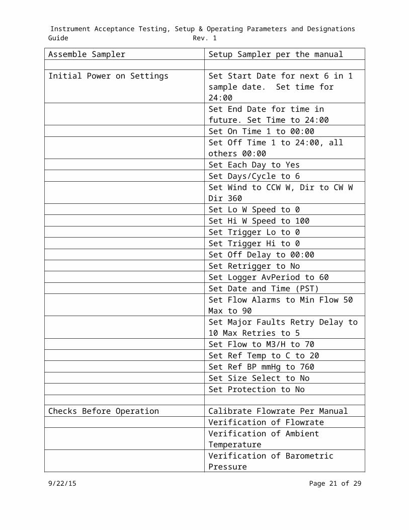
Hi-Vol Setup GuideAssemble Sampler Setup Sampler per the manual
9/22/15 Page 14 of 21

Instrument Acceptance Testing, Setup & Operating Parameters and Designations Guide Rev. 1
Initial Power on Settings Set Start Date for next 6 in 1 sample date. Set time for 24:00Set End Date for time in future. Set Time to 24:00Set On Time 1 to 00:00Set Off Time 1 to 24:00, all others 00:00Set Each Day to YesSet Days/Cycle to 6Set Wind to CCW W, Dir to CW W Dir 360Set Lo W Speed to 0Set Hi W Speed to 100Set Trigger Lo to 0Set Trigger Hi to 0Set Off Delay to 00:00Set Retrigger to NoSet Logger AvPeriod to 60Set Date and Time (PST)Set Flow Alarms to Min Flow 50 Max to 90Set Major Faults Retry Delay to 10 Max Retries to 5Set Flow to M3/H to 70Set Ref Temp to C to 20Set Ref BP mmHg to 760Set Size Select to NoSet Protection to No
Checks Before Operation Calibrate Flowrate Per ManualVerification of FlowrateVerification of Ambient TemperatureVerification of Barometric PressureVerification of Date and Time
Inform the Supervisor when the above HI-Vol checks are done. A HI-Vol that is designated as an extra or spare should be stored in the appropriate area. For field-going HI-Vol, the Supervisor will assign the HI-Vol to a specific site, and HI-Vol will then be verified at the site in accordance with the Guide and Schedule.
Administrative
1. Submit the hard copy of the factory calibration test and validate data to the Senior Office Specialist for scanning and placement in the corresponding acceptance test folder.
2. When the aforementioned is successful, tag the instrument with a green sticker, include the serial number, initial and date. Place the instrument in the appropriate storage location.
9/22/15 Page 15 of 21
Instrument Acceptance Testing, Setup & Operating Parameters and Designations Guide Rev. 1
The instrument is now ready for field use.
9/22/15 Page 16 of 21

Instrument Acceptance Testing, Setup & Operating Parameters and Designations Guide Rev. 1
Instrument Designations
List of EPA FRM and FEM
OzoneTeledyne Advanced Pollution Instrumentation, Model 400E or T400; Advanced Pollution Instrumentation, Model 400/400A; Teledyne Monitor Labs sensor-e™ Model TML-10 Ozone Analyzers; or recordum airpointer® system module 801-004000; Automated Equivalent Method: EQOA-0992-087 “Teledyne Advanced Pollution Instrumentation. Model 400E or T400; Advanced Pollution Instrumentation,. Model 400 or 400A; or Teledyne Monitor Labs sensor-e™ Model TML-10 Ozone Analyzer” operated on any full scale range between 0-100 ppb1 and 0-1000 ppb, with any range mode (Single, Dual, or AutoRange), at any ambient temperature in the range of 5°C to 40°C, and with a TFE filter or a Kynar® DFU. Models 400E, T400 and TML-10: operated with a sample flow rate of 800 ±80 cm3/min (sea level), with the dilution factor set to 1, with Dynamic Zero ON or OFF, with Dynamic Span OFF, with Temp/Press compensation ON, and with or without any of the following options: Internal or external sample pump, Sample/Cal valve option, Internal Zero/Span (IZS), Rack mount with or without slides, analog input option, 4-20 mA isolated current loop output.2 Models 400/400A: operated with the dynamic zero and span adjustment feature (some Model 400 units only) set to OFF, and with or without any of the following options: Zero/Span Valve option, Internal Zero/Span (IZS) option, IZS ozone generator reference feedback option, standard serial port or Multi-drop RS-232, digital status outputs, analog outputs: 100 mV, 1V, 5V, 10V, 4-20 mA current loop, optional metal wool ozone scrubber, optional external sample pump, optional 47 mm diameter filter, optical bench heater, rack mount with slides. airpointer® system module 801-004000 only: operated on any full scale range between 0-0.100 ppm and 0-1.0 ppm, with a PTFE filter element installed in the internal filter assembly, with the software setting: FRM/FEM conform mode; at any temperature in the range of 10°C to 45°C, with either a user- or vendor-supplied vacuum pump capable of providing an absolute pressure of 16 inches mercury or less at 2.5 sLpm; installed in the compact. thermally controlled (-40°C to + 45°C) and weather proof airpointer base unit with integrated data acquisition and management system mounted on a frame, pole, or wall; with or without wireless telemetry; with or without the internal span option as module supplement consisting of ozone generator; with or without modules for other criteria pollutants; with or without analyzer for particulate matter; with or without additional 3rd party sensors for e.g. meteorology, noise, or traffic counting. Operated with the appropriate instrument manual. Note 2 applies to the following Teledyne Advanced Pollution Instrumentation, Models 400E, T400, and Teledyne Monitor Labs, Inc. Sensor-e™ Model TML-10. Federal Register: Vol. 57, page 44565, 09/28/1992; Vol. 63, page 31992, 06/11/1998 Vol. 67, page 57811, 09/12/2002 Latest Modification: 08/2010; 05/2013; 07/2014
Oxides of Nitrogen Teledyne Advanced Pollution Instrumentation Models 200A, 200AU, 200E, 200EU, T200, T200U, T204; Teledyne Analytical Instruments Model 9110A; or Teledyne Monitor Labs sensor-e™ Model TML-41 NO2
Analyzers; or recordum airpointer® System, Module 801-002000; Automated Reference Method: RFNA-1194-099 “Teledyne Advanced Pollution Instrumentation Models 200A, 200AU, 9110A, 200E, 200EU, T200, T200U, T204; Teledyne Analytical Instruments Model 9110A; or Teledyne Monitor Labs, Inc. sensor-e™ Model TML-41 Chemiluminescence Nitrogen Oxides Analyzer,” operated on any full scale range between 0-0.05 ppm and 0-1.0 ppm, with a PTFE filter element or a Kynar® DFU installed in the internal filter assembly, with the following software settings: dynamic zero: OFF or ON; dynamic span: OFF; cal-on-NO2: OFF; dilution factor: OFF or set to 1.0; autocal: ON or OFF; independent range: ON or OFF; autorange: ON or OFF; temperature/pressure compensation: ON; and with or without any of the following options (if available): rack mounts with or without slides, rack mount for external pump, zero/span valves, 4-20 mA analog outputs, status outputs, RS-232 output. Models 200A, 200E, and T200 and TML-41 only: operated at any temperature in the range of 5°C to 40°C, with either a user- or vendor-supplied vacuum pump capable of providing an absolute pressure of 10 inches mercury or less at 2 sLpm, with or without optional internal zero/span (IZS) and permeation tubes for IZS, gold-plated reaction chamber, or Nafion-type sample gas conditioner, ethernet output, control input, analog input option, RS-485 output. Model 200AU, 200EU, and T200U only: operated at any temperature in the range of 20°C to 30°C, with either a 9/22/15 Page 17 of 21

Instrument Acceptance Testing, Setup & Operating Parameters and Designations Guide Rev. 1
user- or vendor-supplied vacuum pump capable of providing an absolute pressure of 4 inches mercury or less at 1 sLpm. Model T204 NOX + O3 Analyzer only: operated on any full scale range between 0-100 ppb and 0-500 ppb, at any operating temperature from 5°C to 40°C, with either a user-or vendor-supplied vacuum pump capable of providing an absolute pressure of 10 inches mercury or less at 3 sLpm, in accordance with the associated instrument manual, and with or without any of the following options: Zero/Span valves, external communication and data monitoring interfaces. Airpointer® system module 801-002000 only: operated on any full scale range between 0-0.05 ppm and 0-1.0 ppm, with a PTFE filter element installed in the internal filter assembly, with the software setting: FRM/FEM conform mode; at any temperature in the range of 10°C to 45°C, with either a user- or vendor-supplied vacuum pump capable of providing an absolute pressure of 16 inches mercury or less at 2.5 sLpm; installed in the compact. thermally controlled (-40°C to + 45°C) and weather proof airpointer base unit with integrated data acquisition and management system mounted on a frame, pole, or wall; with or without wireless telemetry; with or without internal span option as module supplement consisting of permeation oven and permeation tube; with or without modules for other criteria pollutants; with or without analyzer for particulate matter; with or without additional 3rd party sensors for e.g. meteorology, noise, or traffic counting. Operated with the appropriate instrument manual. Note 2 applies to the following Teledyne Advanced Pollution Instrumentation Models 200E, 200EU, T200, T200U, T204 and Teledyne Monitor Labs, Inc. Sensor-e™ Model TML-41. Federal Register: Vol. 59, page 61892, 12/02/1994 Latest modifications: 03/2009; 08/2010; 10/2012; 5/2013; 06/2014; 07/2014
Teledyne Advanced Pollution Instrumentation, Model T500U CAPS Nitrogen Dioxide Analyzer Automated Equivalent Method: EQNA-0514-212 “Teledyne Advanced Pollution Instrumentation, Model T500U cavity attenuated phase shift spectroscopy Nitrogen Dioxide Analyzer”, operated on any full scale range between 0-50 ppb and 0-1000 ppb, with any range mode (Single, Dual, or AutoRange), at any operating temperature from 5°C to 40°C, with a sample particulate filter, with the following software setting: Temperature and Pressure compensation ON; in accordance with the associated instrument manual, and with or without any of the following options: Zero/Span valves, internal Zero/Span permeation oven (IZS), external communication and data monitoring interfaces. Note 2 applies to the Teledyne Advanced Pollution Instrumentation, Model T500U. Federal Register: Vol.79, pages 34734-34735, 06/18/2014
Sulfur DioxideTeledyne Advanced Pollution Instrumentation, Models 100A, 100AS, 100E, 100EU, T100, T100U; Teledyne Analytical Instruments Model 6400A; or Teledyne Monitor Labs sensor-e™ Model TML-50 SO2 Analyzers; or recordum airpointer® system module 801-001000 Automated Equivalent Method: EQSA-0495-100 ‘Teledyne Advanced Pollution Instrumentation Models 100A, 100AS, 100E, 100EU, T100 or T100U; Teledyne Analytical Instruments Model 6400A; or Teledyne Monitor Labs, Inc. sensor-e™ Model TML-50 UV Fluorescent Sulfur Dioxide Analyzer; operated on any full scale range between 0-50 ppb1 and 0-1000 ppb, at any temperature in the range of 5 to 40 degrees C, with a TFE filter element or a Kynar® DFU installed in the filter assembly, with either the vendor-supplied internal pump or a user- or vender-supplied external vacuum pump capable of maintaining an absolute pressure of 35 cm (14 inches) of mercury (or less) at 1.0 standard liter per minute flow rate, with the following software settings: Dynamic zero: OFF or ON; Dynamic span: OFF; AutoCal: ON or OFF; Dual range: ON or OFF; Autorange: ON or OFF; Temp/pressure compensation: ON; dilution factor: OFF or 1.0; and with or without any of the following options (if available for the various models):2 Rack mount with or without chassis slides; Fluorocarbon zero/span valves; Internal zero/span (IZS); Three-point internal zero/span (IZS, option 51C); 4-20 mA, isolated analog outputs; analog input option; External pump; Status outputs; Control inputs; Rack mount for external pump with tray; RS-232 output; Ethernet output; Zero air scrubber; Combustion Filter; SO2 Permeation tube, certified or uncertified, 0.4 ppm @ 0.7 L/min; SO2 Permeation tube, certified or uncertified, 0.8 ppm @ 0.7 L/min. Airpointer® module 801-001000 only: operated on any full scale range between 0-0.05 ppm and 0-1.0 ppm, with a PTFE filter element installed in the internal filter assembly, with the software setting: FRM/FEM conform mode; at any temperature in the range of 10°C to 45°C, with either a user- or vendor-supplied vacuum pump capable of providing an absolute pressure of 16 inches mercury or less at 2.5 sLpm; installed in the compact. thermally controlled (-40°C to + 45°C) and weather proof airpointer base unit with integrated data acquisition and management system mounted on a frame, pole, or wall; with or without wireless telemetry; with or without internal span option as module supplement consisting of permeation oven and permeation tube; with or without modules for other criteria pollutants; with or without analyzer for particulate matter; with or without additional 3rd party sensors 9/22/15 Page 18 of 21

Instrument Acceptance Testing, Setup & Operating Parameters and Designations Guide Rev. 1
for e.g. meteorology, noise, or traffic counting. Operated with the appropriate instrument manual. Note 2 applies to the following Teledyne Advanced Pollution Instrumentation,. Models 100E, 100EU, T100, T100U, and Teledyne Monitor Labs, Inc. Sensor-eTM Model TML-50. Federal Register: Vol. 60, page 17061, 04/04/1995 Latest Modification: 08/2010; 05/2013; 07/2014
Carbon MonoxideTeledyne Advanced Pollution Instrumentation Models 300, 300E, 300EU, T300, T300U or Teledyne Monitor Labs sensor-e™ Model TML-30 CO Analyzer; or recordum airpointer® system module 801-003000; Automated Reference Method: RFCA-1093-093 “Teledyne Advanced Pollution Instrumentation Models 300, 300E, 300EU, T300, T300U or Teledyne Monitor Labs, Inc. sensor-e™ Model TML-30, Gas Filter Correlation Carbon Monoxide Analyzer,” operated on any full scale range between 0-10 ppm and 0-50 ppm (0 - 0.1 ppm for Models 300EU and T300U), at any temperature in the range of 15°C to 35°C for Model 300 or 10°C to 40°C for Models 300E, 300 EU, T300, T300U and TML-30, with a 5-micron TFE filter element or a Kynar® DFU installed in the sample filter assembly, with the dynamic zero and span adjustment set to Off for Model 300, and with or without any of the following options:2 Option 50, Zero/Span Valves with pressurized span gas and shutoff valve; Option 51, Zero/Span Valves with pressurized span gas and shutoff valve and Internal Zero Air Generator; Option 52, Zero/Span Valves; Option 53, Zero/Span Valves with Internal Zero Air Generator; Rack Mount with slides; RS-232 serial port with status outputs; analog input option; and (for Models 300E, 300EU, T300, T300U and TML-30) 4-20 mA isolated outputs. airpointer® model 801-003000 only: operated on any full scale range between 0-10 ppm and 0-50 ppm, with a PTFE filter element installed in the internal filter assembly, with the software setting: FRM/FEM conform mode; at any temperature in the range of 10°C to 45°C, with either a user- or vendor-supplied vacuum pump capable of providing an absolute pressure of 16 inches mercury or less at 2.5 sLpm; installed in the compact. thermally controlled (-40°C to + 45°C) and weather proof airpointer® base unit with integrated data acquisition and management system mounted on a frame, pole, or wall; with or without wireless telemetry; with or without internal dilution system with internal span gas bottle; with or without modules for other criteria pollutants; with or without analyzer for particulate matter; with or without additional 3rd party sensors for e.g. meteorology, noise, or traffic counting. Operated with the appropriate instrument manual. Note 2 applies to the following Teledyne Advanced Pollution Instrumentation Models 300E, 300EU, T300, T300U, and Teledyne Monitor Labs, Inc. Sensor-e™ Model TML-30. Federal Register: Vol. 58, page 58166, 10/29/1993 Latest Modification: 08/2010; 05/2013; 07/2014
PM10 – FH62C14 Thermo Scientific Model 5014i or Thermo Scientific FH62C14-DHS Continuous Ambient Particle Monitor Automated Equivalent Method: EQPM-0609-183 “Thermo Scientific Model 5014i or FH62C14-DHS Continuous Ambient Particle Monitor,” operated at a flow rate of 16.67 liters per minute for 24-hour average measurements configured for PM2.5 with a louvered PM10 size selective inlet as specified in 40 CFR 50 Appendix L, Figs. L-2 through L-19, a PM2.5 BGI Inc. Very Sharp Cut Cyclone (VSCC™) particle size separator, inlet connector, sample tube, DHS heater with 35% RH threshold, mass foil kit, GF10 filter tape, 8-hour filter change, and operational calibration and servicing as outlined in the 5014i Continuous Ambient Particulate Monitor or FH62C14-DHS Continuous Ambient Particulate Monitor operating manual. Federal Register: Vol. 74, page 28696, 06/17/2009 Latest modification: 03/2010
PM10 – 5014i Thermo Scientific Model 5014i or Thermo Scientific FH62C14-DHS Continuous Ambient Particle Monitor Automated Equivalent Method: EQPM-0609-183 “Thermo Scientific Model 5014i or FH62C14-DHS Continuous Ambient Particle Monitor,” operated at a flow rate of 16.67 liters per minute for 24-hour average measurements configured for PM2.5 with a louvered PM10 size selective inlet as specified in 40 CFR 50 Appendix L, Figs. L-2 through L-19, a PM2.5 BGI Inc. Very Sharp Cut Cyclone (VSCC™) particle size separator, inlet connector, sample tube, DHS heater with 35% RH threshold, mass foil kit, GF10 filter tape, 8-hour filter change, and operational calibration and servicing as outlined in the 5014i
9/22/15 Page 19 of 21

Instrument Acceptance Testing, Setup & Operating Parameters and Designations Guide Rev. 1
Continuous Ambient Particulate Monitor or FH62C14-DHS Continuous Ambient Particulate Monitor operating manual. Federal Register: Vol. 74, page 28696, 06/17/2009 Latest modification: 03/2010
PM10 – BAM 1020 Met One Instruments BAM-1020 PM10-2.5 Measurement System Automated Equivalent Method: EQPM-0709-185 “Met One Instruments BAM-1020 PM10-2.5 Measurement System,” consisting of 2 BAM-1020 monitors, the first of which (PM2.5 measurement) is configured as a PM2.5 FEM (EQPM-0308-170). The second BAM-1020 monitor (PM10 measurement) is configurable as a PM2.5 FEM (EQPM-0308-170), but set to monitor PM10. The BAM-1020 monitors are collocated to within 1-4 meters of one another. The BAM-1020 performing the PM2.5 measurement is equipped with Met One Instruments, Inc. P/N BX-Coarse interface board and accessories; the units are interconnected to provide concurrent sampling and to report PM10-2.5 concentrations directly to the user. Both units are operated in accordance with BAM-1020 PM-Coarse Addendum Rev. 5-5 or later and the BAM-1020 Operations Manual Rev. D or later. Federal Register: Vol. 74, page 28241, 06/15/2009
PM2.5 – 5014i Thermo Scientific Model 5014i or Thermo Scientific FH62C14-DHS Continuous Ambient Particle Monitor Automated Equivalent Method: EQPM-0609-183 “Thermo Scientific Model 5014i or FH62C14-DHS Continuous Ambient Particle Monitor,” operated at a flow rate of 16.67 liters per minute for 24-hour average measurements configured for PM2.5 with a louvered PM10 size selective inlet as specified in 40 CFR 50 Appendix L, Figs. L-2 through L-19, a PM2.5 BGI Inc. Very Sharp Cut Cyclone (VSCC™) particle size separator, inlet connector, sample tube, DHS heater with 35% RH threshold, mass foil kit, GF10 filter tape, 8-hour filter change, and operational calibration and servicing as outlined in the 5014i Continuous Ambient Particulate Monitor or FH62C14-DHS Continuous Ambient Particulate Monitor operating manual. Federal Register: Vol. 74, page 28696, 06/17/2009 Latest modification: 03/2010
PM2.5 – BAM 1020 Met One Instruments BAM-1020 PM10-2.5 Measurement System Automated Equivalent Method: EQPM-0709-185 “Met One Instruments BAM-1020 PM10-2.5 Measurement System,” consisting of 2 BAM-1020 monitors, the first of which (PM2.5 measurement) is configured as a PM2.5 FEM (EQPM-0308-170). The second BAM-1020 monitor (PM10 measurement) is configurable as a PM2.5 FEM (EQPM-0308-170), but set to monitor PM10. The BAM-1020 monitors are collocated to within 1-4 meters of one another. The BAM-1020 performing the PM2.5 measurement is equipped with Met One Instruments, Inc. P/N BX-Coarse interface board and accessories; the units are interconnected to provide concurrent sampling and to report PM10-2.5 concentrations directly to the user. Both units are operated in accordance with BAM-1020 PM-Coarse Addendum Rev. 5-5 or later and the BAM-1020 Operations Manual Rev. D or later. Federal Register: Vol. 74, page 28241, 06/15/2009
PM2.5 – 2025i Thermo Scientific Partisol®-Plus 2025 Sequential PM2.5 Air Sampler or Thermo Fisher Scientific Partisol® 2025i Sequential PM2.5 Air Sampler or Rupprecht & Patashnick Partisol®-Plus 2025 PM2.5 Sequential Sampler Manual Reference Method: RFPS-0498-118 or Manual Equivalent Method: EQPM-0202-145 “Thermo Scientific Partisol®-Plus 2025 PM2.5 Sequential Air Sampler” or “Thermo Fisher Scientific Partisol® 2025i PM2.5 Sequential Air Sampler” or “Rupprecht & Patashnick Partisol®-Plus 2025 PM2.5 (FEM) Sequential Air Sampler,” configured with a BGI VSCC™ Very Sharp Cut Cyclone particle size separator with either R&P-specified machined or molded filter cassettes, for 24-hour continuous sampling periods. Partisol®-Plus 2025 to be operated with any software version 1.003 through 1.5 and Partisol® 2025i with firmware version 2.0 or greater, and with the modified filter shuttle mechanism. Method to be operated in accordance with the Partisol®-Plus 2025 or Partisol®
9/22/15 Page 20 of 21
Instrument Acceptance Testing, Setup & Operating Parameters and Designations Guide Rev. 1
2025i instruction manual, as appropriate, with the VSCC™ supplemental manual, and with the requirements and sample collection filters specified in 40 CFR Part 50, Appendix L. Federal Register: Vol. 67, page 15567, 04/02/2002 Latest modification: 06/ 2011
LeadInductively Coupled Plasma - Mass Spectrometry (US EPA/OAQPS) Manual Equivalent Method: EQL-0510-191 “Determination of Lead Concentration in TSP by Inductively Coupled Plasma Mass Spectrometry (ICP-MS) with Heated Ultrasonic Nitric and Hydrochloric Acid Filter Extraction,” where total suspended particulate matter (TSP) is collected according to 40 CFR Appendix B to part 50, EPA Reference Method for the Determination of Suspended Particulate Matter in the Atmosphere (High-Volume Method), extracted with a solution of nitric and hydrochloric acids, heated to 80° C and sonicated for one hour, brought to a final volume of 40mL, and analyzed by Inductively Coupled Plasma-Mass Spectrometry (ICP-MS) based on EPA SW-846 Method 6020A. Federal Register: Vol.75, page 30022, 05/28/2010
9/22/15 Page 21 of 21