assets.highways.gov.ukassets.highways.gov.uk/specialist-information/guidance... · web viewmobile...
TRANSCRIPT

NOT PROTECTIVELY MARKED
Enterprise Architecture 2009
Technology Policy Level 0
Multi-Channel Architecture
November 2009
Reference:
Version: 0.1
Editor Mike Williams
Status: Draft
Date: 23 November 2009
23/11/2009 HA Technology Policy v0.1 Page 1 of 18

NOT PROTECTIVELY MARKED
CONTENTS
1 INTRODUCTION.........................................................................................................4
1.1 SYSTEM CONTEXT AND SCOPE...................................................................................4
1.2 INTRODUCTORY MATERIAL..........................................................................................4
2 COMMUNICATION CHANNELS................................................................................6
2.1 POLICY......................................................................................................................6
2.2 RATIONALE.................................................................................................................6
2.3 VOICE........................................................................................................................7
2.4 DATA.........................................................................................................................7
2.5 VIDEO AND STILL IMAGE.............................................................................................7
2.6 TEXT.........................................................................................................................8
2.7 IN-CAR......................................................................................................................8
2.8 ROADSIDE..................................................................................................................9
3 DELIVERY INTERFACES.........................................................................................14
3.1 POLICY....................................................................................................................14
3.2 RATIONALE..............................................................................................................14
3.3 INTERNAL (HA) INTERFACES.....................................................................................14
3.4 EXTERNAL INTERFACES............................................................................................15
3.5 Third-Party Data Feeds..........................................................................................16
23/11/2009 HA Technology Policy v0.1 Page 2 of 18

NOT PROTECTIVELY MARKED
Document Control
Document Title L0 Technology Policy – Multi-Channel ArchitectureAuthor Mike WilliamsOwner Ivan WellsDistribution EA Pages – HA Portal and PartnerNETDocument Status Draft
Revision History
Version Date Description Author0.1 23rd November 2009 First draft Mike Williams
Forecast Changes
Version
Date Description
1.0 4Q2009 Issued version following a peer review.
Reviewer List
Name RoleMike Edwards ReviewerOminder Bharj ReviewerVarious External review
Approvals
Name Title Date VersionIvan Wells Strategy and Architecture
Document References
Ref Document Title[1] Public Sector Network, Report of Industry Working Group, V0.6, Date 30 July 2008
23/11/2009 HA Technology Policy v0.1 Page 3 of 18

NOT PROTECTIVELY MARKED
1 INTRODUCTION
1.1 System Context and ScopeThis policy covers Channels and their Delivery Interfaces as shown in Figure 1 below.
Figure 1 – Multi-Channel Architecture EARM Context
The scope of this policy, in the context of the EA Reference Model is defined by the system boundary as shown in red above. Similarly, for the Technical Reference Model, see Figure 2 below.
Figure 2 - TRM Context
23/11/2009 HA Technology Policy v0.1 Page 4 of 18

NOT PROTECTIVELY MARKED
1.2 Introductory material
The Agency requires a heterogeneous architecture which is:
Multi-vendor (device manufacturer), Multi-service provider, Multi-channel, Multi-protocol, Multi-device, and Multi-platform.
The nearest equivalent model which covers the commercial as well as technical considerations, is the Service-oriented, four layer model of the Public Sector Network (PSN); three layers containing procurable services and one transport and infrastructural layer, as shown in Figure 3 below.
Figure 3 - PSN 4-Layer Procurement Model (Source: Ref. [1])
The channels and their associated delivery interfaces are characterised by a combination of the relevant devices and communications media.
23/11/2009 HA Technology Policy v0.1 Page 5 of 18

NOT PROTECTIVELY MARKED
2 COMMUNICATION CHANNELS
2.1 Policy
The Agency shall develop and maintain a Multi-Channel Architecture (MCA) in support of its business and operational capabilities, especially those relating to the collection and dissemination of information.
Figure 4 – Multi-Channel Communications Capabilities
2.2 RationaleMulti-media capabilities are required to support customers and the various means of communications available.
In order to facilitate this diverse MCA and associated multi-protocol capability, the network will be logically segmented into Virtual Networks as illustrated in Figure 5 below.
Figure 5 - Logical Channels
The diverse range of channels, devices and delivery channels is discussed in the following sections.
23/11/2009 HA Technology Policy v0.1 Page 6 of 18

NOT PROTECTIVELY MARKED
2.3 VoiceThe Agency’s Multi-Channel Architecture must support both fixed (wireline) and mobile voice communications.
Fixed voice communication channels currently include:
Emergency Roadside Telephones (ERT’s). The Public Switch Telephone Network (PSTN). The Government Telecommunications Network (GTN) which will be superseded
by the Public Sector Network (PSN).
Mobile voice communication channels currently include:
Terrestrial Trunked Radio (TETRA) which comprises a suite of open digital trunked radio standards used by Private Mobile Radio users such as the Highways Agency and Emergency Services (Police, Fire and Ambulance). Generally we refer to this as Airwave – the service currently provided in the UK by O2.
Mobile phone networks - GSM (Global System for Mobile communications) and 3G (third generation).
2.4 DataThe Agency’s Multi-Channel Architecture must support all current and future data requirements as follows.
Data channels may be classified in terms of:
Traffic Data; and Business Data.
Traffic data must be collected, processed and disseminated in a real-time channel. Historical data must be stored and made available from a Data Warehouse1 which forms part of the Business Intelligence2 capability – this may be considered as a logically separate ‘channel’.
Business data is associated with the Agency’s information processing architecture. This is stored and accessed according to two principal classifications of data:
Structured data is held primarily in Relation DataBase Management Systems (RDBMS’s) and accessed through Line of Business (LoB) applications services typically through SQL (Structured Query Language).
Unstructured data is held in a number of knowledge-based repositories, including:o Content Management Systems (CMS), accessed via a web server/browser;o Document Management Systems (DMS), accessed by downloading
individual documents into office systems such as a word processor or spreadsheet; and
o Message stores, e.g. Electronic Mailboxes, accessed via an email client.
2.5 Video and Still Image OutputsThis capability relates to the output side of the channel, i.e. for customers (including staff and partners) to be able to view the images (See Section 2.8.1 for the input side). Output devices include:
Dedicated CCTV displays/controllers with “joystick” controls for Pan-Tilt-Zoom (PTZ) cameras.
1 For a definition see http://en.wikipedia.org/wiki/Data_warehouse.
2 For a definition see http://en.wikipedia.org/wiki/Business_intelligence.
23/11/2009 HA Technology Policy v0.1 Page 7 of 18

NOT PROTECTIVELY MARKED
Flat TV digital displays for “video walls”.
Browser-based displays.
2.6 Text
The Agency’s Multi-Channel Architecture must support all current and future text-based technologies as follows.
Text-based channels include:
SMS (Short Message Service). Electronic Mail. Instant Messaging.
Trials have been undertaken in the past for SMS-based alerts in applications such as pre-trip planning – this showed that there are applications which customers do value.
Electronic mail is used extensively within the Agency and its partners. Customer contact is also available via this channel.
Instant messaging is not currently used but may become a future channel within the collaboration space.
2.7 In-CarThe Agency’s Multi-Channel Architecture must support all current and future In-Car technologies as follows.
Digital RadioDigital Audio Broadcasting (DAB) is a digital radio technology for broadcasting radio stations, used in several countries, particularly in the UK and Europe.
Figure 6 - Traffic Radio
Traffic Radio (www.trafficradio.org.uk) is a current service for keeping customers up-to-date with what’s happening on England’s motorways, major A roads and London’s main road network 24-hours a day, 365- days of the year.
With information provided directly from the Highways Agency’s National Traffic Control Centre (NTCC) and Transport for London’s (TfL) Traffic Control Centre’s, traffic bulletins are updated every ten minutes at peak times and every 20 minutes at other times.
RDS and RDS-TMCThe Radio Data System (RDS) arrived in the UK in the early 90’s, adding a basic data and text service to FM radio. Most FM radio stations in the UK use RDS. Along with the audio, small amounts of text and data are transmitted with the radio signal, and can be picked up and processed by radios which have an RDS decoder built-in. Such radio receivers can display this information.
A very useful bit of information sent, is something called the Traffic Announcement (TA) flag, which can be switched on when a radio station starts a travel report, and switched off at the
23/11/2009 HA Technology Policy v0.1 Page 8 of 18
NOT PROTECTIVELY MARKED
end. The practical upshot of this is that an RDS radio can switch to a station carrying travel news, if necessary pausing other audio output, whilst local travel news is broadcast.
RDS-TMC stands for Radio Data Systems Traffic Message Channel. It provides road traffic information sent over FM radio to special in-car receivers. In the UK, RDS-TMC data is collected, and sent out over-air on specific FM radio stations. Some satellite navigation devices are capable of receiving RDS-TMC data, and updating routes to avoid traffic hotspots.
Future developments - CVHSCo-operative Vehicle Highway Systems (CVHS) offers a potential opportunity to move towards the ideal of 100% reliable and safe road journeys. New developments in automotive electronics are rapidly moving us towards intelligent vehicles and hence to Intelligent Transport Systems (ITS). This enabling technology facilitates the provision of warnings to drivers or remote actuation of automotive systems to improve travel safety. However to allow these systems to develop to a stage of full efficient automation, information will be required from the road network. The infrastructure will need to communicate with vehicles’ on-board computers to provide real-time travel conditions and close the information loop which could eventually lead to fully automated control systems.
This technology also supports Telematics applications like Norwich Unon’s “Pay-As-You-Drive” insurance although here the roadside infrastructure is bypassed via mobile telephone networks (GPRS).
2.8 RoadsideThe Agency’s Multi-Channel Architecture must support all current and future roadside technologies as follows.
2.8.1 Video and Still Image InputsThe capability in this section relates to the input side of the channel, i.e. for devices to generate the images.
CCTV CamerasThe HA has around 1,500 CCTV cameras that monitor traffic flows at strategic locations, to assist in the management of the road network. The cameras are positioned, usually on poles, at regular intervals to provide an overview of real-time traffic conditions for the HA’s National and Regional Traffic Control Centre’s (NTCC and RCCs). This enables traffic information to be provided through a variety of information and media services which drivers can use to plan their journeys. The cameras also provide the HA with a valuable appreciation of how road-users make use of the network which helps ensure future public investment is made most effectively.
The CCTV cameras do not record data unless a specific incident has occurred, for example a serious collision. CCTV images are shared with the Police for road traffic purposes and criminal law enforcement. Data from CCTV cameras may also be shared with Local Authority Traffic Control Centre’s and Traffic Information Providers to help with traffic management but images are ‘blanked’ if the cameras are zoomed in past a certain level, which prevents individuals or number plates being identifiable. HA CCTV
images can be seen by the public on www.trafficengland.co.uk.
ANPR CamerasThe HA currently operates an ANPR (Automatic Number Plate Recognition) camera system through the National Traffic Control Centre (NTCC) with 1,100+ cameras. These cameras can be identified by their bright green casings, and are spread across 485 sites. The data is anonymised and transmitted to the NTCC
23/11/2009 HA Technology Policy v0.1 Page 9 of 18

NOT PROTECTIVELY MARKED
at least every 5 minutes. Once this has been matched to a record from an adjacent camera or a defined period has lapsed the data is deleted. The only information being retained being the average journey time for that section at that time. No-one has access to the full number plate data. ANPR cameras are used to measure the flow rate to monitor traffic movement on the network and to measure journey times. This process is entirely automatic and the vehicle registration numbers are not visible to us.
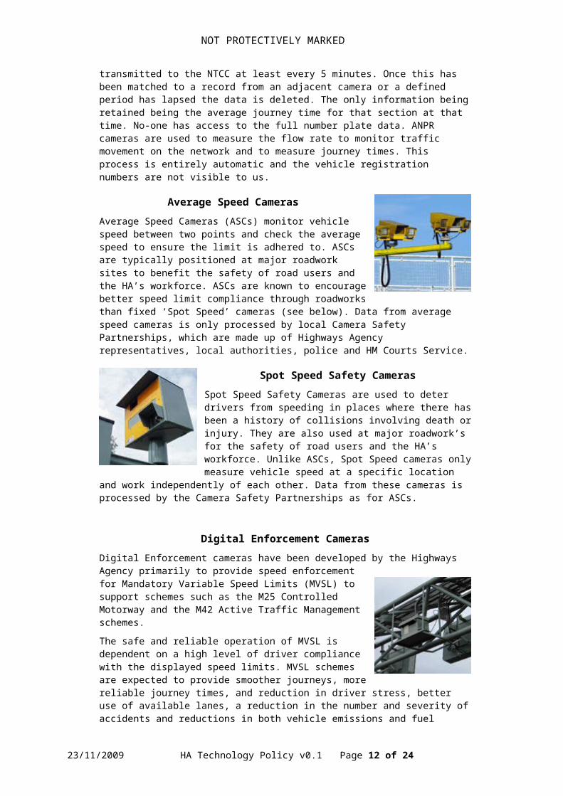
Average Speed CamerasAverage Speed Cameras (ASCs) monitor vehicle speed between two points and check the average speed to ensure the limit is adhered to. ASCs are typically positioned at major roadwork sites to benefit the safety of road users and the HA’s workforce. ASCs are known to encourage better speed limit compliance through roadworks than fixed ‘Spot Speed’ cameras (see below). Data from average speed cameras is only processed by local Camera Safety Partnerships, which are made up of Highways Agency representatives, local authorities, police and HM Courts Service.
Spot Speed Safety CamerasSpot Speed Safety Cameras are used to deter drivers from speeding in places where there has been a history of collisions involving death or injury. They are also used at major roadwork’s for the safety of road users and the HA’s workforce. Unlike ASCs, Spot Speed cameras only measure vehicle speed at a specific location and work independently of each other. Data from these cameras is processed by the Camera Safety Partnerships as for ASCs.
Digital Enforcement CamerasDigital Enforcement cameras have been developed by the Highways Agency primarily to provide speed enforcement for Mandatory Variable Speed Limits (MVSL) to support schemes such as the M25 Controlled Motorway and the M42 Active Traffic Management schemes.
The safe and reliable operation of MVSL is dependent on a high level of driver compliance with the displayed speed limits. MVSL schemes are expected to provide smoother journeys, more reliable journey times, and reduction in driver stress, better use of available lanes, a reduction in the number and severity of accidents and reductions in both vehicle emissions and fuel consumption.
Automatic Motorway Indicators (AMI) will display the speed limit over each lane, and these are linked to digital cameras. Evidence collected will be encrypted and transmitted to the evidence processing office. Digital Enforcement Cameras are operated with the support of Local Police forces or Safety Camera Partnerships.
2.8.2 Traffic Sensor Data/TelemetryANPR is used for journey times. The other detectors described below are just some examples and range from (As-Is) deployed technology to theoretical research (candidate To-Be). They are included here to show there is a range of technology that we need to support in our To-Be Architecture.
23/11/2009 HA Technology Policy v0.1 Page 10 of 18

NOT PROTECTIVELY MARKED
Inductive LoopsToday inductive loops are most commonly used for traffic detection. New detector technologies are currently being investigated and those which have the potential to be deployed on Agency Roads in the near future are:
Microwave/Radar Infrared Detection Magnetic Anomaly Detector Fibre Optic Network/Longitudinal Detection Acoustic Detection
Microwave/RadarThis product has been designed for the detection and monitoring of vehicles at signalled junctions and other applications where the detection of moving targets is required in a long zone extending from the detector.
Their primary use is for detection associated with traffic signals, although they are a potential alternative to inductive loops for other Agency applications such as incident detection.
Infrared DetectionInfrared detectors find radiation ranging between 100-105 GHz. The detectors convert received energy into electrical signals that determine the presence of a vehicle by real-time signal processing. There are active and passive infrared detector models which have different detection abilities.
Passive detectors measure the energy emitted by a target or the image of the detection zone.
Active detectors emit invisible infrared low-energy by light-emitting diodes or high energy by laser diodes to the detector zone and measures the time for reflected energy to return to the detector. A lower return time denotes the presence of a vehicle.
The detectors measure vehicle speed by transmitting two or more beams and recording the times at which the vehicle enters the detection zone of each beam.
Magnetic Anomaly DetectorMagnetic detectors sense vehicles by measuring effects of the vehicles’ metallic components on the Earth’s magnetic field.
Magnetic detectors can detect volume, speed, presence and occupancy. Their configurations may be single, double, or multiple, depending on monitoring requirements. They generally require multiple detectors per lane due to the narrow focus of the detection field.
A micro-loop detector is a type of point detector. The installation requires a hole in the pavement, one inch in diameter and 20 inches deep, with a straight one fourth inch saw cut. Although there is still disruption to traffic, the micro-loop is considered to be “non-intrusive” compared to inductive loops. The 3M type of MAD mounts under the road in a plastic pipe. This makes it particularly well suited for viaducts and bridges.
23/11/2009 HA Technology Policy v0.1 Page 11 of 18
NOT PROTECTIVELY MARKED
Fibre Optic DetectorsFibre Optic Sensors have no electronic components, which gives them high reliability and immunity to electro-magnetic interference. With the available bandwidth, over 100 sensors can be multiplexed together on a single fibre. Remote interrogation of the sensors is possible from a distance as great as 50 kilometres.
Fibre optic sensors have the potential to measure vehicle dynamics in the road, and early tests of longitudinal sensors (Fibre Optic Longitudinal Detector) have shown they could potentially provide a cost effective alternative to traditional loop and WIM technologies. These are currently experiemental.
Acoustic DetectionPassive acoustic detectors can detect volume, speed, occupancy, and classification. They measure the acoustic energy or audible sounds produced by a variety of sources within a passing vehicle.
Sound energy increases when a vehicle enters the detection zone and decreases when it leaves. A detection threshold determines the termination of the vehicle presence signal. Sounds from locations outside the detection zone are attenuated.
The detector measures multi-lane traffic count, occupancy, and vehicle speed. Each detector can replace up to five dual-loops when installed 'side-fire'. These are currently experiemental.
Weather Sensor Data/Telemetry
Weather Detection Systems use different types of sensors to detect current weather conditions such as:
Atmospheric water vapour Pavement temperatures Fog density Ice levels Snow levels
These sensors are often integrated with other weather-related technologies to forecast weather conditions. Road weather information systems, for example, transmit pavement temperatures and other information to traffic management centres which can, in turn, make decisions on whether to apply anti-icing chemicals or begin snowplough operations, as well as alert travellers to adverse driving conditions.
2.8.3 Signals
Below are examples of signals in use on the Highways Agency network.
23/11/2009 HA Technology Policy v0.1 Page 12 of 18

NOT PROTECTIVELY MARKED
Ramp Metering
Ramp metering is a key measure for reducing delays at junctions. It works by managing the traffic on slip roads.
During busy periods, signals release just a few vehicles at a time. This prevents merging and mainline traffic from bunching together and creating a bottleneck which delays everyone.
Sensors in the road monitor the congestion and adjust the signal timings. The system also monitors the slip road to minimise the possibility of queues forming on local authority roads.
23/11/2009 HA Technology Policy v0.1 Page 13 of 18

NOT PROTECTIVELY MARKED
Central Reserve Post-mounted Signals (Matrix Signals)
Caters for up to 3-lane motorways and major trunk roads.
Spaced at 3km intervals.
Limited to display advisory fog warnings, speed restrictions and lane closures with amber flashing warning lanterns.
Slip Road Post-mounted Signals
Normally situated in pairs at entry slip roads.
Similar to matrix signals; displays advisory fog warnings, speed restrictions and lane closures with amber flashing lanterns.
Additional function to display red lanterns to allow mandatory closures of slip roads only.
Gantry Mounted Signals
Allows flexibility for individual lane signalling (display applies to the lane below each signal).
Displays advisory fog warnings, speed restrictions, lane closures and lane diversions.
Can display red “X” and red flashing lanterns to provide a mandatory “stop” signal.
Spaced at 1km intervals.
2.8.1 Variable Message SignsBelow are examples of signs (which are all types of VMS) in use on the Highways Agency network. For further details see “A guide to Variable Message Signs”.
Enhanced Message Sign (EMS)
Can be mounted either on cantilever posts or alongside Gantry Mounted Signals.
Display information about incidents and hazards.
Two lines of 12 or 16 characters are used for tactical messages and three lines of 12 or 18 characters are used for strategic messages.
23/11/2009 HA Technology Policy v0.1 Page 14 of 18

NOT PROTECTIVELY MARKED
These legends inform motorists of the reason why the signals have been set.
Message Sign Mark 2 (MS2)
Mounted on cantilever posts.
Display information about incidents, hazards and campaigns.
Usually a VMS with 2 lines of 12 characters, together with an enhanced matrix indicator (EMI), which is a slightly larger Matrix Signal.
Now obsolete - replaced with MS3 for new installations.
Message Sign Mark 3 (MS3)Mounted on Cantilever Posts only.
Display information about incidents, hazards, campaigns and restrictions and can include a matrix signal aspect.
Two lines of 16 characters or 3 lines of 18 characters.
Advanced Message Indicator (AMI)Variable Speed Limit Signs.
Lane Control Indicators.
Dynamic Lane Control Unit.
Lane Control Signal.
Controlled Motorway Indicator.
The above signs can be set automatically by Motorway Incident Detection Automatic Signalling (MIDAS) or manually by control room staff.
23/11/2009 HA Technology Policy v0.1 Page 15 of 18

NOT PROTECTIVELY MARKED
3 DELIVERY INTERFACES
3.1 PolicyThe Agency shall develop and maintain multiple delivery interfaces (and devices) in support of its Multi-Channel Architecture (MCA).
Figure 7 – MCA Delivery Interface Capabilities
3.2 RationaleEach channel may be required to support multiple devices, interfaces and protocols. The diverse range of delivery interfaces is discussed in the following sections.
3.3 Internal (HA) Interfaces
3.3.1 NetworkThere will be a single (logical) converged IP network with defined services and associated Quality of Service (QoS) for each channel within the MCA.
The network will support a number of bearer services including wireline (fibre and copper) technologies as well as wireless (e.g. GPRS/3G, WiMAX, etc).
The Service Provider shall act as a Virtual Network Operator, thus making possible Fixed Mobile Convergence and thereby delivering a “one stop shop” for the entire Agency’s communications.
3.3.2 Mobile DataMobile data services shall be provided by the Virtual Network Operator. A range of devices shall be supported as required for specific business applications such as Personal Digital Assistants (PDA’s), Smartphones and mobile data terminals.
23/11/2009 HA Technology Policy v0.1 Page 16 of 18

NOT PROTECTIVELY MARKED
3.3.3 Enterprise Service BusThe Enterprise Service Bus (ESB) is an integration design pattern which employs Message-Oriented Middleware (MOM). This middleware, or integration, layer sits on top of the network layer and provides value-added services such as XML message routing and transformations. Its purpose is to facilitate integration between loosely-coupled services in a SOA-runtime environment. Interfaces to the ESB constitute “Smart Endpoints” and legacy adaptors for a particular software environment such as Java, C#, C++ or C++ embedded.
3.3.4 Unified Operator InterfaceThe Unified Operator Interface (UOI) constitutes a new, strategic HA Desktop which provides flexible access to all services required to fulfil a particular role. This includes access to both Business and Operational Support Services. This concept has already been developed and deployed within the NTCC although several functions, like the National Incident Liaison Officer (NILO) have been added in a non-integrated fashion since the NTCC contract was let. It therefore needs updating and extending to encompass the RCC’s Incident Management functions as part of the Mosaic Project.
The desktop workstation will primarily utilise a browser-based (thin client) with plug-ins as appropriate to meet the business requirements – these may include:
Rich Client functionality (such as AJAX) for Rich Internet Applications based on the Web 2.0 paradigm.
Instant Messaging. Media player for video playback. Telephony client for VoIP.
Given the preference for thin-client, the design shall not preclude the inclusion of fat client applications, if required, although that need may be met through Citrix.
3.3.5 VoiceThere are a number of existing voice interfaces (handsets) including fixed-line telephones on the GTN network, Emergency Response Telephones, Private Mobile Radio (Tetra/Airwave), Automatic Call Distribution (ACD) terminals/turrets and mobile telephones. Some convergence is anticipated in this area due to trends in Voice-over-IP (VoIP) and fixed-mobile convergence although the interfaces are largely determined by individual applications and their associated devices.
3.4 External Interfaces
3.4.1 B2B Gateways
The principal Business-to-Business (B2B) gateway is a Datex II data feed to external parties in the Travel Information Highway (TIH) community. Similar gateway interfaces are envisaged for data exchange with Local Highway Authorities (LHA’s) for Integrated Network Management and emergency services for Incident Management.
There is also a separate interface for the video channel (VIH client).
3.4.2 Web Portal
Presently, there is a plethora of disparate web sites which need to be brought together under a common portal framework. This needs to accommodate browsers in customer’s PC’s at home and work, mobile devices (Smartphones and PDA’s) and kiosks (HA Information Points).
23/11/2009 HA Technology Policy v0.1 Page 17 of 18

NOT PROTECTIVELY MARKED
3.4.3 Voice
External public interfaces for the voice channel currently comprise the HA Information Line (HAIL), Traffic Radio and an Interactive Voice Response (IVR) facility at the NTCC. For operational partners there are a number of existing voice interfaces (handsets) including fixed-line telephones, Private Mobile Radio (Tetra/Airwave) with other emergency services, and mobile telephones. Little change is anticipated in this area.
3.4.4 In-Car
In-car devices essentially comprise satellite navigation (sat-nav) systems and, in future, will be expanded to include the On-Board Units (OBU’s) used for Telematics in Cooperative Vehicle Highways Systems (CVHS). The sat-nav devices interface indirectly via Value-Added Service Providers (such as TrafficMaster and TomTom) although future CVHS interfaces are anticipated through the UTMC architecture (node-type “E” also known as Vehicle-to-Infrastructure and/or Infrastructure-to-vehicle).
3.5 Third-Party Data FeedsA number of third-party data feeds are used by the Agency, including:
Thematic data sets from Ordnance Survey and others under the Pan Government Agreement (PGA2).
Traffic data from third-parties, such as TrafficMaster.
Note that in the current (As-Is) state, there are a number of external data feeds into the Business Intelligence domain. However, this reflects the fact that the hosting of numerous outsourced systems is both fragmented and external to the “HA-Cloud”. In future, such systems will be brought into the “HA Cloud” by re-hosting them within the HA’s virtual data centre (currently contracted to Atos Origin).
23/11/2009 HA Technology Policy v0.1 Page 18 of 18