circabc.europa.eu file · web viewin the case of vehicles equipped with steering wheel and bench...
TRANSCRIPT

COMMISSION DELEGATED REGULATION (EU) No …/..
of XXX
supplementing Regulation (EU) No 167/2013 of the European Parliament and of the Council with regard to vehicle functional safety requirements for the approval of
agricultural and forestry vehicles
(Text with EEA relevance)

DISCUSSION PAPER
DRAFT CONCEPT RVFSR
This document does not represent an official position of the European Commission. It is a tool to explore the views of interested parties. The suggestions contained in this document do not prejudge the form and content of any possible future proposal by the European Commission.

ANNEX XIIIRequirements on vehicle occupant protection, including interior fittings, head
restraints, seat belts, vehicle doors
PART 1
1. Definitions
For the purposes of this Annex:
Definitions for the protection of drive components, in accordance with the requirements laid down on the basis of Article 18 (4) of Regulation (EU) 167/2013, are valid for this Annex.
1.1. ‘Interior fittings’ mean the interior parts of the passenger compartment other than the interior rear-view mirrors and include
— the layout of the controls;
— the roof;
— power-operated windows, roof panel and partition systems.
1.2. ‘Level of the instrument panel’ means the line defined by the points of contact of vertical tangents to the instrument panel.
1.3. ‘Power-operated windows’ means windows which are closed by power supply of the vehicle.
1.4 ‘Opening’ is the maximum unobstructed aperture between the upper edge or the leading edge, depending on the closing direction, of a power-operated window or partition or roof panel and the vehicle structure which forms the boundary of the window, partition or roof panel, when viewed from the interior of the vehicle or, in the case of partition system, from the rear part of the passenger compartment.
PART 2
Interior fittings
1. SPECIFICATIONS
1.1. Interior parts of the passenger compartment excluding the side doors
1.1.1. Environment of driving seat and passenger seats, if fitted
1.1.1.1. The safety distance zone A above the SIP of the driving seat and located in front of it, as determined in Figure 1, shall not contain any dangerous roughness or sharp edges, likely to increase the risk of serious injury to the occupants. If parts contained in the safety distance

zone A above the SIP, located in front of it, comply with the requirements in points 1.1.2 to 1.2, they shall be deemed to also comply with this requirement.
Figure 1
1.1.1.2. The safety distance zone A, whose centre is 670 mm above the centre of the front edge of the front passenger seat, if fitted, and located in front of it, as determined in Figure 2, shall not contain any dangerous roughness or sharp edges, likely to increase the risk of serious injury to the occupants. If parts contained in the safety distance zone A above the SIP, located in front of it, comply with the requirements in points 1.1.2 to 1.2, they shall be deemed to also comply with this requirement.
Figure 2
1.1.1.3. In the case of vehicles equipped with steering wheel and bench seats or bucket seats in more than one row, the environment of the rear passenger seats, if fitted, shall comply with the requirements of Annex XVII of the Regulation (EU) No 3/2014.1
1 Commission Delegated Regulation (EU) No 3/2014 of 24 October 2013 supplementing Regulation (EU) No 168/2013 of the European Parliament and of the Council with regard to vehicle functional safety requirements for the approval of two- or three-wheel vehicles and

1.1.2. In particular, for tractors with maximum design speed exceeding 40 km/h, any metal support fittings shall have no protruding edges.
1.1.3. The lower edge of the instrument panel, installed in tractors with maximum design speed exceeding 60 km/h, shall be rounded to a radius of curvature of not less than 19 mm.
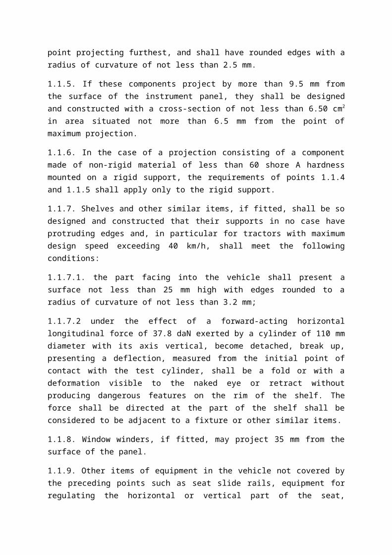
1.1.4. Switches, pull-knobs, etc, made of rigid material, which, measured in accordance with the method described in 3 from 3.2 mm to 9.5 mm from the panel, shall have a cross-sectional area of not less than 2 cm2, measured 2.5 mm from the point projecting furthest, and shall have rounded edges with a radius of curvature of not less than 2.5 mm.
1.1.5. If these components project by more than 9.5 mm from the surface of the instrument panel, they shall be designed and constructed with a cross-section of not less than 6.50 cm2 in area situated not more than 6.5 mm from the point of maximum projection.
1.1.6. In the case of a projection consisting of a component made of non-rigid material of less than 60 shore A hardness mounted on a rigid support, the requirements of points 1.1.4 and 1.1.5 shall apply only to the rigid support.
1.1.7. Shelves and other similar items, if fitted, shall be so designed and constructed that their supports in no case have protruding edges and, in particular for tractors with maximum design speed exceeding 40 km/h, shall meet the following conditions:
1.1.7.1. the part facing into the vehicle shall present a surface not less than 25 mm high with edges rounded to a radius of curvature of not less than 3.2 mm;
1.1.7.2 under the effect of a forward-acting horizontal longitudinal force of 37.8 daN exerted by a cylinder of 110 mm diameter with its axis vertical, become detached, break up, presenting a deflection, measured from the initial point of contact with the test cylinder, shall be a fold or with a deformation visible to the naked eye or retract without producing dangerous features on the rim of the shelf. The force shall be directed at the part of the shelf shall be considered to be adjacent to a fixture or other similar items.
1.1.8. Window winders, if fitted, may project 35 mm from the surface of the panel.
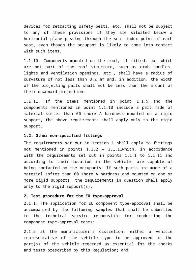
1.1.9. Other items of equipment in the vehicle not covered by the preceding points such as seat slide rails, equipment for regulating the horizontal or vertical part of the seat, devices for retracting safety belts, etc. shall not be subject to any of these provisions if they are situated below a horizontal plane passing through the seat index point of each seat, even though the occupant is likely to come into contact with such items.
1.1.10. Components mounted on the roof, if fitted, but which are not part of the roof structure, such as grab handles, lights and ventilation openings, etc., shall have a radius of curvature of not less than 3.2 mm and, in addition, the width of the projecting parts shall not be less than the amount of their downward projection.
quadricycles (OJ L 7, p. 1, 10.01.2014)
1.1.11. If the items mentioned in point 1.1.9 and the components mentioned in point 1.1.10 include a part made of material softer than 60 shore A hardness mounted on a rigid support, the above requirements shall apply only to the rigid support.
1.2. Other non-specified fittings
The requirements set out in section 1 shall apply to fittings not mentioned in points 1.1.2 – 1.1.11which, in accordance with the requirements set out in points 1.1.1 to 1.1.11 and according to their location in the vehicle, are capable of being contacted by the occupants. If such parts are made of a material softer than 60 shore A hardness and mounted on one or more rigid supports, the requirements in question shall apply only to the rigid support(s).
2. Test procedure for the EU type-approval
2.1.1. The application for EU component type-approval shall be accompanied by the following samples that shall be submitted to the technical service responsible for conducting the component type-approval tests:
2.1.2 at the manufacturer's discretion, either a vehicle representative of the vehicle type to be approved or the part(s) of the vehicle regarded as essential for the checks and tests prescribed by this Regulation; and
2.1.3. at the request of the aforesaid technical service, certain components and certain samples of the materials used.
3. METHOD OF MEASURING PROJECTIONS
3.1. To determine the amount by which an item projects in relation to the panel on which it is mounted, a 165 mm sphere shall be moved along and be kept in contact with the component under consideration, starting from the initial position of contact with the component under consideration. The projection's value is the largest of all possible variations «y», the variation measured from the centre of the sphere perpendicular to the panel.
If the panels and components, etc., are covered with materials softer than 50 Shore A hardness, the procedure for the measuring of projections described above shall apply only after the removal of such materials.
The projection of switches, pull-knobs, etc., situated in the reference area shall be measured by using the test apparatus and procedure described below:
3.2. Apparatus
3.2.1 The measuring apparatus for projections shall consist of a hemispherical headform 165 mm in diameter, in which there is a sliding ram of 50 mm diameter.
3.2.2. Relative positions of the flat end of the ram and the edge of the headform shall be shown on a graduated scale, on which a mobile index shall register the maximum measurement achieved when the apparatus is moved away from the item tested. A minimum
distance of 30 mm shall be measurable; the measuring scale shall be graduated in half-millimeters to make possible an indication of the extent of the projections in question.
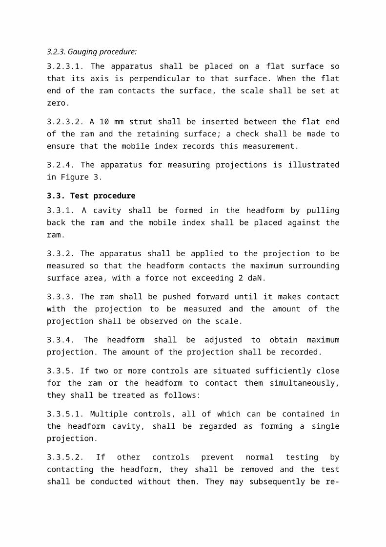
3.2.3. Gauging procedure:
3.2.3.1. The apparatus shall be placed on a flat surface so that its axis is perpendicular to that surface. When the flat end of the ram contacts the surface, the scale shall be set at zero.
3.2.3.2. A 10 mm strut shall be inserted between the flat end of the ram and the retaining surface; a check shall be made to ensure that the mobile index records this measurement.
3.2.4. The apparatus for measuring projections is illustrated in Figure 3.
3.3. Test procedure
3.3.1. A cavity shall be formed in the headform by pulling back the ram and the mobile index shall be placed against the ram.
3.3.2. The apparatus shall be applied to the projection to be measured so that the headform contacts the maximum surrounding surface area, with a force not exceeding 2 daN.
3.3.3. The ram shall be pushed forward until it makes contact with the projection to be measured and the amount of the projection shall be observed on the scale.
3.3.4. The headform shall be adjusted to obtain maximum projection. The amount of the projection shall be recorded.
3.3.5. If two or more controls are situated sufficiently close for the ram or the headform to contact them simultaneously, they shall be treated as follows:
3.3.5.1. Multiple controls, all of which can be contained in the headform cavity, shall be regarded as forming a single projection.
3.3.5.2. If other controls prevent normal testing by contacting the headform, they shall be removed and the test shall be conducted without them. They may subsequently be re-installed and tested in their turn with other controls that have been removed to facilitate the procedure.

<< To be named Figure 3 >>
4. APPARATUS AND PROCEDURE FOR APPLICATION OF POINT 1.1.1
Those parts (switches, pull-knobs etc.) which can be contacted by using the apparatus and procedure described below shall be considered as being likely to be contacted by the knees of an occupant:
4.1. Apparatus
Diagram of apparatus
4.2. Procedure
The apparatus may be placed in any position below the instrument panel so that:
– the plane XX' remains parallel to the median longitudinal plane of the vehicle
– the axis X can be rotated above and below the horizontal through angles up to 30°.
In carrying out the test referred to in this point, all materials of less than 60 shore A hardness shall be removed.
PART 3
Head restraints, if fitted
Head restraints, if fitted shall comply with the provisions of UNECE Regulation No 25, as referenced in Annex I.
PART 4
Seat belts
The requirements for seat belts are referred to in no. 48 of Annex I to the Regulation (EU) No 167/2013.
PART 5
Vehicle doors, if fitted

Vehicle doors, with powered windows and powered roof hatches, if fitted, shall comply with paragraphs 5.8.1 to 5.8.5 of UNECE Regulation No 21, as referenced in Annex I.

ANNEX XXIIRequirements on the maximum laden mass
1. Definitions
For the purposes of this Annex,
Definitions of ‘drawbar towed vehicle’ and ‘rigid drawbar towed vehicle’, in accordance with the requirements laid down on the basis of Article 17(2)(b) and (4) of Regulation (EU) No 167/2013, are valid for this Annex.
1.1 ‘Technically permissible maximum laden mass’ means the maximum mass allocated to a vehicle on the basis of its construction features and its design performances irrespective from the load capacity of the tyres or tracks.
1.2 ‘Technically permissible maximum mass per axle’ means the mass corresponding to the maximum permissible static vertical load transmitted to the ground by the wheels of the axle, on the basis of the construction features of the axle and of the vehicle and their design performances irrespective from the load capacity of the tyres or tracks.
2. Requirements
2.1. The technically permissible maximum laden mass as stated by the manufacturer shall be accepted by the type-approval authority as the maximum permissible laden mass provided that:
2.1.1. the results of any tests which that administration makes, in particular those in respect of braking and steering, are satisfactory;
2.1.2. the technically permissible maximum laden mass and the technically permissible maximum mass per axle depending on the vehicle category does not exceed the values given in Table 1.
Table 1
Maximum Permissible Laden Mass and Maximum Permissible Mass per Axle Depending on the Vehicle Category
Vehicle category
Number of axles
Maximum permissible mass (t)
Maximum permissible mass per axle
Driven axle (t) Non-driven axle (t)
T1, T2, T4.1, T4.2
2 18 (laden) 11.5 10
3 24 (laden) 11.5 (d) 10 (d)
T1 4 or more 32 (laden) (c) 11.5 (d) 10 (d)

T3 2 or 3 0.6 (unladen) (a) (a)
T4.3 2, 3 or 4 10 (laden) (a) (a)
C N/A 32 N/A N/A
R 1 N/A 11.5 10
2 18 (laden) 11.5 (b)
3 24 (laden) 11.5 (b)
4 or more 32 (laden) 11.5 (b)
S 1 N/A 11.5 10
2 18 (laden) 11.5 (b)
3 24 (laden) 11.5 (b)
4 or more 32 (laden) 11.5 (b)
(a) It is not necessary to establish an axle limit for vehicle categories T3 and T4,3, as they have by definition limitations on the maximum permissible laden and/or unladen mass.
(b) The corresponding value for the sum of the axle maximum permissible mass is the sum of the axle weights in Annex I, points 3.1 to 3.3, to Council Directive 96/53/EC2.
(c) Where the driving axle is fitted with twin tyres and air suspension or suspension recognized as being equivalent within the European Union as defined in Annex II to Directive 96/53/EC, or where each driving axle is fitted with twin tyres and the maximum weight of each axle does not exceed 9.5t.
(d) The corresponding value for the sum of the axle maximum permissible mass is the sum of the axle weights in Annex I, point 3.5, to Directive 96/53/EC.
2.2. Whatever the state of loading of the tractor, the mass transmitted to the road by the wheels on the steering axle shall not be less than 20 % of the unladen mass of that tractor.
2.3. Sum of the technically permissible maximum masses per axle
2.3.1 For vehicles of categories T and C and of categories R and S, which do not impose any significant static vertical load on the tractor (drawbar towed vehicle), the sum of the maximum permissible masses per axle shall be equal to or higher than the maximum permissible laden mass of the vehicle.
2.3.2 For vehicles of categories R and S imposing a significant static vertical load on the tractor (rigid drawbar towed vehicle), the maximum permissible mass of the vehicle shall
2 Council Directive 96/53/EC of 25 July 1996 laying down for certain road vehicles circulating within the Community the maximum authorized dimensions in national and international traffic and the maximum authorized weights in international traffic (ОJ L 235, 17.9.1996, p. 59).

be considered to be the sum of the maximum permissible masses per axle and shall be applicable for type approval purposes.

ANNEX XXXRequirements on tyres
1. Definitions
For the purposes of this Annex,
1.1 ‘Cyclic service’ means the condition that applies when the load on the tyre cycles between the fully loaded and the unloaded condition;
1.2 ‘High and sustained torque’ means the condition that occurs due to a load on the drawbar or hitch.
1.3 ‘Applicable tyre inflation pressure’ means the internal pressure of the tyre, with the tyre at ambient temperature (i.e. cold tyre pressure), recommended in conformity to the load, speed and service conditions of the vehicle. It does not include any pressure built up due to tyre usage and is expressed in kPa.
1.4 ‘Maximum load rating’ means the mass which a tyre can carry when operated in conformity with requirements governing utilisation specified by the tyre manufacturer.
1.5 ‘Maximum permissible mass per axle according to tyre specification’ means the mass corresponding to the maximum permissible static vertical load that can be transmitted to the ground by the wheels of the axle as restricted by the maximum load rating of tyre types that can be fitted to the vehicle as listed in the information document.
2. Requirements
2.1. Requirements applying to the component type-approval of tyres
2.1.1 Provisions for pneumatic tyres designed primarily for agricultural vehicles with diagonal or bias-ply and bias-belted construction with a reference speed not exceeding 40 km/h (i.e. speed symbol A8), as well as radial tyres designed primarily for construction application purposes (i.e. tyres marked "Industrial", "IND", "R-4" or "F-3").
2.1.1.1. All tyres conforming to the relevant type shall be marked in conformity with points 2.1.1.2. to 2.1.1.2.4.
2.1.1.2. Specific requirements for markings.
2.1.1.2.1. Tyres shall bear the following markings, in conformity with ISO 4223-1:2002/Amd 1:2011, including:
– the tyre size designation;– the load capacity index (i.e. a numerical code which indicates the load the
tyre can carry at the speed corresponding to the associated speed category);– the speed category symbol (i.e. a symbol which indicates the maximum
speed at which the tyre can carry the load corresponding to its load index); and
– the word "TUBELESS" if the tyre is designed for use without an inner tube.

2.1.1.2.2. Tyres shall bear the following additional markings:
– the manufacturer's trade name or mark;– the inflation pressure that shall not be exceeded for the purpose of bead
seating during tyre mounting;– in case of implement tyres the service description (i.e. load index and speed
category symbol) shall be supplemented with the indication whether it applies to "drive wheel" or to "free rolling wheel" or to both; and
– the date of manufacture in the form of a group of four digits, the first two showing the week and the last two the year of manufacture.
2.1.1.2.3. All markings mentioned in points 2.1.1.2.1. and 2.1.1.2.2. shall be legibly and permanently moulded into or onto the sidewall and produced as part of the process during manufacture. The use of branding or other methods of marking after completion of the original manufacturing process is not permitted.
2.1.1.2.4. In line with Article 34(2) of Regulation (EU) No 167/2013, no type-approval mark is required for pneumatic tyres designed primarily for agricultural vehicles with diagonal or bias-ply and bias-belted construction with a reference speed not exceeding 40 km/h (i.e. speed symbol A8), as well as radial tyres designed primarily for construction application purposes (i.e. tyres marked "Industrial", "IND", "R-4" or "F-3") approved in accordance with this Regulation.
The information document and information folder that shall be submitted with the application for type-approval of those tyres are specified in the models set out in Article 68(a) of Regulation (EU) No 167/2013.
A unique type-approval number, the model of which is set out in Article 68(h) of Regulation (EU) No 167/2013, shall be assigned to each type-approved tyre and a type-approval certificate, the model of which is set out in Article 68(c) of Regulation (EU) No 167/2013, shall be issued.
2.1.2. New pneumatic tyres conforming to the type complying with the requirements set out in points 2.1.1. to 2.1.1.2.4 may continue to be placed on the market until 31 December 2018.
2.1.2.1. Tyres that were manufactured prior to the date set out in point 2.1.2. which do not comply with the requirements of points 2.1.3. to 2.1.3.1. and which comply with the requirements set out in points 2.1.1. to 2.1.1.2.4. may be sold for a period not exceeding 30 months from that date.
2.1.3. Requirements for pneumatic tyres designed primarily for agricultural vehicles other than those set out in points 2.1.1. to 2.1.1.2.4.
2.1.3.1. Tyres not covered by the provisions of points 2.1.1 to 2.1.1.2.4. shall conform to the types approved under the relevant UNECE regulations.
2.2. Requirements for the approval of a type of vehicle with regard to the installation of

tyres
2.2.1. Specific requirements for the installation of tyres on vehicles with a maximum design speed not exceeding 65 km/h.
2.2.1.1. Subject to the provisions of point 2.2.1.2. all tyres fitted to vehicles, including any spare tyre, shall be type-approved according to UNECE Regulation No 106 as referenced in Annex I.
2.2.1.1.1. For the purpose of vehicle type-approval in accordance with Regulation (EU) No 167/2013, tyres designed primarily for agricultural vehicles with diagonal or bias-ply and bias-belted construction with a reference speed not exceeding 40 km/h (i.e. speed symbol A8), as well as radial tyres designed primarily for construction application purposes (i.e. tyres marked "Industrial", "IND", "R-4" or "F-3"), may until 31 December 2017 be type-approved according to this Regulation instead.
2.2.1.2. Where a vehicle is designed for conditions of use which are incompatible with the characteristics of tyres type-approved according to UNECE Regulation No 106, as referenced in Annex I, or this Regulation and it is therefore necessary to fit tyres with different characteristics, the requirements of point 2.2.1.1. do not apply, provided that the following conditions are met:
the tyres are in accordance with Regulation (EC) No 661/2009 of the European Parliament and of the Council3 (i.e. type-approved according to UNECE regulations Nos 30, 54 and 117 as referenced in Annex I to this Regulation) or type-approved according to UNECE Regulation No 75, as referenced in Annex I, and
the approval authority and technical service are satisfied that the tyres fitted are suitable for the operating conditions of the vehicle. The nature of the exemption and reasons for acceptance shall be clearly stated in the test report.
2.2.2. Specific requirements for the installation of tyres on vehicles with a maximum design speed exceeding 65 km/h.
2.2.2.1. Subject to the provisions of point 2.2.2.2., all tyres fitted to vehicles, including any spare tyre, shall be in accordance with Regulation (EC) No 661/2009 (i.e. type-approved according to UNECE Regulations Nos 30, 54 and 117 as referenced in Annex I).
2.2.2.2. Where a vehicle is designed for conditions of use which are incompatible with the characteristics of tyres type-approved in accordance with Regulation (EC) No 661/2009 and it is therefore necessary to fit tyres with different characteristics, the requirements of point 2.2.2.1. do not apply, provided that the following conditions
3 Regulation (EC) No 661/2009 of the European Parliament and of the Council of 13 July 2009 concerning type-approval requirements for the general safety of motor vehicles, their trailers and systems, components and separate technical units intended therefor (OJ L 200, 31.7.2009, p. 1).

are met:
the tyres are type-approved according to UNECE Regulation No 75; as referenced in Annex I, and
the approval authority and technical service are satisfied that the tyres fitted are suitable for the operating conditions of the vehicle. The nature of the exemption and reasons for acceptance shall be clearly stated in the test report.
2.2.3. General requirements for the installation of tyres
2.2.3.1 All tyres normally fitted to one axle shall be of the same type, with the exception of the cases mentioned in points 2.2.4.1.1 and 2.2.4.1.2.
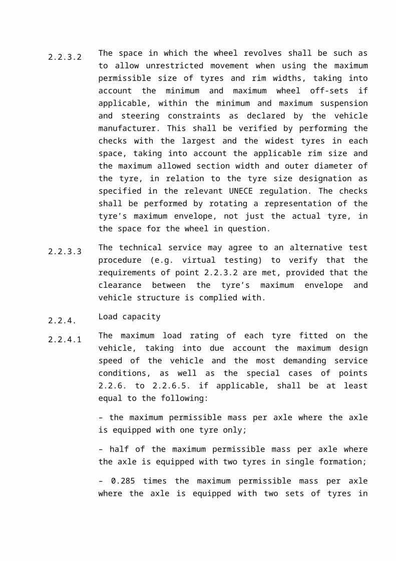
2.2.3.2 The space in which the wheel revolves shall be such as to allow unrestricted movement when using the maximum permissible size of tyres and rim widths, taking into account the minimum and maximum wheel off-sets if applicable, within the minimum and maximum suspension and steering constraints as declared by the vehicle manufacturer. This shall be verified by performing the checks with the largest and the widest tyres in each space, taking into account the applicable rim size and the maximum allowed section width and outer diameter of the tyre, in relation to the tyre size designation as specified in the relevant UNECE regulation. The checks shall be performed by rotating a representation of the tyre’s maximum envelope, not just the actual tyre, in the space for the wheel in question.
2.2.3.3 The technical service may agree to an alternative test procedure (e.g. virtual testing) to verify that the requirements of point 2.2.3.2 are met, provided that the clearance between the tyre’s maximum envelope and vehicle structure is complied with.
2.2.4. Load capacity
2.2.4.1 The maximum load rating of each tyre fitted on the vehicle, taking into due account the maximum design speed of the vehicle and the most demanding service conditions, as well as the special cases of points 2.2.6. to 2.2.6.5. if applicable, shall be at least equal to the following:
– the maximum permissible mass per axle where the axle is equipped with one tyre only;
– half of the maximum permissible mass per axle where the axle is equipped with two tyres in single formation;
– 0.285 times the maximum permissible mass per axle where the axle is equipped with two sets of tyres in dual (twin) formation;
– 0.20 times the maximum permissible .mass per axle where the axle is equipped with two sets of tyres in triple formation.

2.2.4.1.1 In case where dual or triple formations are composed by tyres of different types (i.e. tyre size designations and service descriptions) the following apply:
the tyres shall have the same overall diameter;
the tyres shall be of the same “category of use”, “ structure” and “speed category symbol” as defined in paragraphs 2.1.3, 2.1.4 and 2.1.5 of UNECE regulation 106, as referenced in Annex I;
the vehicle shall be equipped symmetrically;
the sum of the maximum load ratings of all tyres fitted to the axle shall be at least 1.14 times the maximum permissible axle mass in the case of dual formation and 1.2 times the maximum permissible axle mass in the case of triple formation;
the share of the maximum permissible mass per axle on each tyre of the formation shall not exceed the maximum load rating of each tyre;
the inflation pressure of each tyre in the formation shall conform to the recommendation of the tyre manufacturer taking into account the actual load on each tyre and the service conditions.
2.2.4.1.2 When a vehicle may be fitted on each axle with tyres for which the sum of maximum load rating is less than the maximum permissible mass per axle, the requirements of points 2.2.4.1 and 2.2.4.1.1 apply with the maximum permissible mass per axle according to the tyre specification instead of the maximum permissible mass per axle.
The maximum permissible mass per axle according to the tyre specification and the maximum permissible mass per axle are the ones declared by the vehicle manufacturer.
The owner’s manual, the information document and the certificate of conformity shall mention the values of mass per axle for each one of them depending on the maximum permissible mass per axle according to the tyre specification.
2.2.4.2 The maximum load rating of a tyre is determined as follows:
2.2.4.2.1 In the case of tyres identified by speed symbol D (i.e. 65 km/h) or lower the ‘table load-capacity variation with speed’ as referred to in paragraph 2.30 of UNECE Regulation No 106, as referenced in Annex I, for its specific category of use is taken into account. The table shows, as a function of the load-capacity indices and nominal-speed-category symbols, the load variations which a pneumatic tyre can withstand taking into account the maximum design speed of the vehicle.
2.2.4.2.2 In the case of tyres identified by speed symbol F (80 km/h) or higher, type-approved according to UNECE Regulation No 54, the ‘table load-capacity variation with speed’ as referred to in paragraph 2.29 of that Regulation is taken into account.

The table shows, as a function of the load-capacity indices and nominal-speed-category symbols, the load variations which a pneumatic tyre can withstand taking into account the maximum design speed of the vehicle.
2.2.4.2.3 In the case of tyres type-approved according to UNECE Regulation No 75, the ‘table load-capacity variation with speed’ as referred to in paragraph 2.27 of that Regulation is taken into account. The table shows, as a function of the load-capacity indices and nominal-speed-category symbols, the load variations which a pneumatic tyre can withstand taking into account the maximum design speed of the vehicle.
2.2.4.3 The applicable tyre inflation pressures shall be stated on the vehicle (e.g. on one or more labels). The information shall be clearly legible without the need to remove any parts with the use of tools and shall be affixed in a way that it is not easily removed. The relevant information concerning load and speed indices as well as the applicable tyre inflation pressures shall be stated clearly in the instruction manual of the vehicle in order to ensure that suitable replacement tyres with an appropriate load capacity shall be fitted when necessary, once the vehicle has been put into service.
2.2.4.3.1 The load capacity index indicated in the information document shall be the lowest grade which is compatible with the maximum permissible load on the tyre in question. Tyres with a higher grade may be fitted.
2.2.5. Speed capacity
2.2.5.1 Every tyre fitted normally on the vehicle shall bear a speed category symbol.
2.2.5.1.1 The speed category symbol shall be compatible with the maximum design speed.
2.2.5.1.2 The adjusted load rating as referred to in points 2.2.4.2.1. to 2.2.4.2.3. shall be taken into account.
2.2.5.2 The relevant information and the applicable tyre inflation pressure shall be stated clearly in the vehicle owner’s handbook in order to ensure that suitable replacement tyres with an appropriate speed capacity shall be fitted when necessary, once the vehicle has been put into service.
2.2.5.2.1 The speed category as indicated in the information document shall be the lowest grade which is compatible with the maximum design vehicle speed. Tyres with a higher grade may be fitted.
2.2.6. Specific requirements for vehicles fitted with tyres identified by speed symbols corresponding to a maximum design speed not exceeding 65 km/h (i.e. up to symbol D).
2.2.6.1 Cyclic service
2.2.6.1.1 In cyclic service:

2.2.6.1.1.1 unloading shall occur before road transport;
2.2.6.1.1.2 vehicles equipped with injectors, or any other ground engaging attachment (e.g. ploughs) or dragging objects are considered to be operating in a high torque mode;
2.2.6.1.1.3 vehicles towing trailers are also considered to be operating in a high torque mode when operating on slopes greater than 11o (20 %).
2.2.6.1.2 In case tyres classified in category of use 'Tractor - Steering wheel' and marked 'FRONT', 'F-1', 'F-2' or 'F-3' operated at speeds up to a maximum speed of 10 km/h on a tractor equipped with a 'Front end loader' the maximum load on a tyre shall not exceed 2.0 times the load corresponding to the load index marked on the tyre.
2.2.6.1.3 In case tyres classified in category of use 'Tractor - Drive wheel' operating in field applications with 'high and sustained torque' (e.g. ploughing) the maximum load on a tyre shall not exceed the load corresponding to the load index marked on the tyre multiplied by 1.07 for tyres with speed symbol A8 or 1.15 for tyres with speed symbol D.
2.2.6.1.4 In case tyres classified in category of use 'Tractor - Drive wheel' operating in field applications without 'high and sustained torque' and up to a maximum speed of 10 km/h (excluding hillside operations over 20% slope, as mentioned in point 2.2.6.1.1.3) the maximum load on a tyre shall not exceed the load corresponding to the load index marked on the tyre multiplied by 1.70.
2.2.6.1.5 In case tyres classified in category of use 'Tractor - Drive wheel' operating in field applications without 'high and sustained torque' and a maximum speed not exceeding 15 km/h (excluding hillside operations over 20% slope, as mentioned in point 2.2.6.1.1.3) the maximum load on a tyre shall not exceed the load corresponding to the load index marked on the tyre multiplied by 1.55.
2.2.6.1.6 In case tyres classified in category of use 'Implement, installed on T-, R- and S-category vehicles, identified by speed symbols A6 or A8 with a nominal rim diameter code lower than 24, operating in 'cyclic high load variation' (i.e. when one way the vehicle is empty and on the other way the technically permissible maximum laden mass of the vehicle exceeds two times the unladen mass in running order) the variation in load capacity with speed identified in point 2.2.4.2.1. may be increased by up to 20% for Free Rolling wheels or by up to 43% in case of Drive wheels.
2.2.6.1.7 The minimum tyre inflation pressure to be adopted for the cases of the points 2.2.6.1.2 to 2.2.6.1.6 shall be provided by the tyre manufacturer.
2.2.6.2 In case of "Improved Flexion Tyre" or "Very High Flexion Tyre" classified in category of use 'Tractor – Drive wheel' (marked with prefix IF or VF) operated at

speeds up to a maximum speed of 10 km/h fitted to a vehicle equipped with a 'Front end loader', the maximum load on a tyre shall not exceed 1.40 times the load corresponding to the load index marked on the tyre and the relevant reference pressure shall be increased by 40 kPa.
2.2.6.2.1 In the case of "Improved Flexion Tyre" classified in category of use 'Tractor Drive Wheel', marked with prefix IF and with suffix 'CFO', fitted to T-category vehicles operating in field applications without 'high and sustained torque' (excluding hillside operations over 20% slope, as mentioned in point 2.2.6.1.1.3) the maximum load on a tyre shall not exceed the load corresponding to the load index marked on the tyre multiplied by 1.55 for operations up to a maximum speed of 15 km/h and by 1.30 for operations up to a maximum speed of 30 km/h.
2.2.6.3 In case of tyres classified in category of use 'Tractor – Drive wheel' marked with speed symbols A6 or A8 fitted to agricultural trailers operating at speeds between 25 km/h and 40 km/h, the maximum load on a tyre shall not exceed 1.20 times the load corresponding to the load index marked on the tyre.
2.2.6.4 In case of tyres classified in category of use 'Forestry machines' fitted to traction wheels of T-category vehicles, for forestry purposes, with high and sustained torque applications in forestry service at speeds up to 10 km/h (including the cases of points 2.2.6.1.1.2 and 2.2.6.1.1.3), the maximum load on a tyre shall not exceed the load corresponding to the load index marked on the tyre.
2.2.6.5 In case of tyres classified in category of use 'Implement', marked with speed symbols A6 or A8, fitted to free rolling steering wheels of T--category vehicles, the load capacity identified as ‘Free Rolling’, taking into account the maximum design speed of the vehicle as well as the variation of load capacity with speed according to definition 2.30 of UNECE Regulation No 106 shall be multiplied by up 0.80.
2.2.6.6 The relevant information and the applicable tyre inflation pressure shall be stated clearly in the instruction manual of the vehicle in order to ensure that suitable replacement tyres with an appropriate load capacity shall be fitted when necessary, once the vehicle has been put into service.
2.2.6.7 In case the applicable tyre inflation pressure for tyres fitted to agricultural or forestry vehicles exceeds 500 kPa, the tyre ground pressure exerted on a flat surface shall not exceed 0.8 MPa.
2.2.6.7.1 The tyre ground pressure is the average load transmitted by the correctly inflated tyre, through its contact area, onto a flat surface. The vertical force is taken under static conditions on the axis of the wheel taking into account the maximum permissible mass per axle as declared by the manufacturer. The tyre contact area consists of the flat surface contained within the convex polygonal curve circumscribing the smallest area containing all points of contact between the tyre
and the ground.
3. Accredited in-house technical services of the manufacturer
A tyre manufacturer may be designated as accredited in-house technical service to perform self testing, in accordance with Article 60 of Regulation (EU) No 167/2013.