6mycommittees.api.org/standards/cre/some/standards... · web view... cylindrical roller bearings,...
TRANSCRIPT

5/9/2023 1 of 41R 26
6.9.2 Rolling Element Bearings
Discussion: Table 6.9.-2, 6.9-5 and 6.9-6.
Table 6.9-2. lists the bearings used in API applications. Table 6.9-5 was developed to illustrate each of these types and provide the industry Series designation for each type. Table 6.9-6 compares the ABMA and ISO standards which cover these bearings.
Table 6.9-5 Types of rolling element bearings
Type Series Example
Radial
Single row deep groove ball bearings
6 000
Double row deep groove ball bearings (Duplex)
4 000
Cylindrical roller bearings N, NU, NJ Second letter describes configuration of the races. I.e illustration is NU which has “inner Flg”
on OD and non on ID.
Spherical roller bearings 20 000
Tapered roller bearings
Single or double (shown)
Different for ABMA and ISO
ABMA ISO
5/9/2023

5/9/2023 2 of 41R 26
EH,EL,H,HH,HM,J,L,LL,LM,M
(These may be inch series)
30 000
or XXX as described in
ISO 355:1977
Para 3
(Metric size)
Radial / Thrust
Single row angular contact ball bearing
7 000
Double row angular contact ball bearing
5 000 (US Nomenclature) or 3 000 (European
Nomenclature)
For reference, a comparison of the ABA Standards and ISO standard scopes appear in Table 6.9-6
Highlighted standards are presently referred to in the SP.
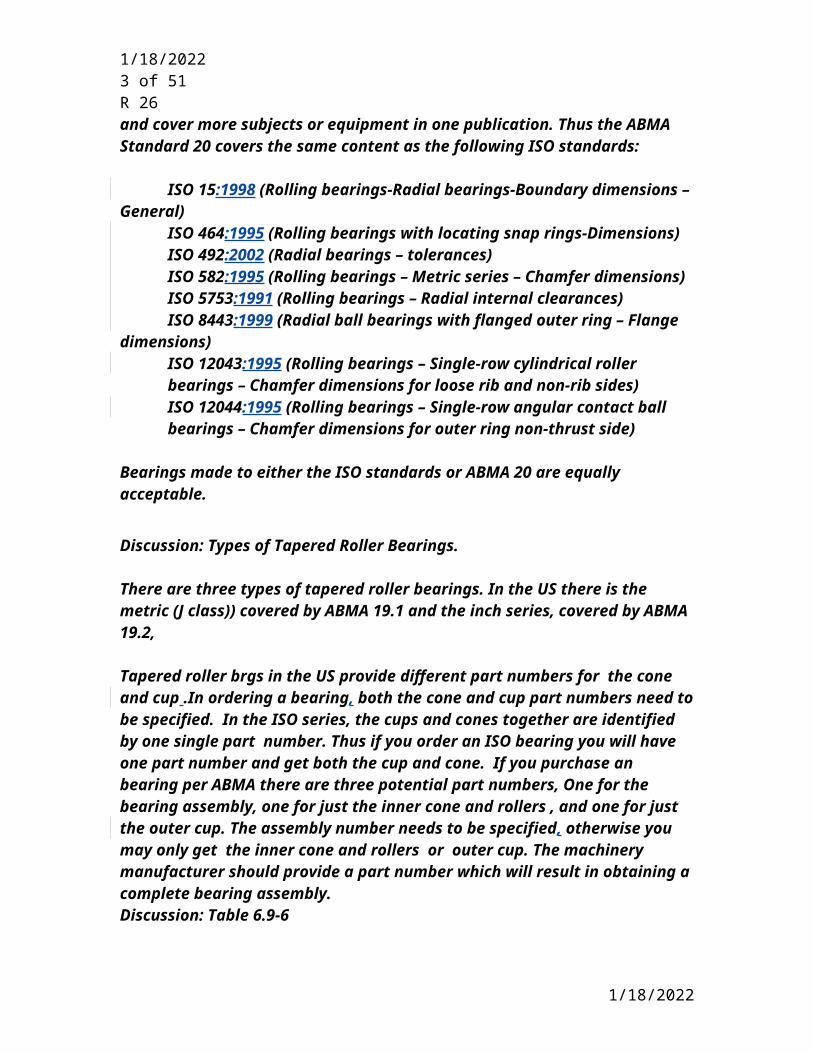
As typical between the US customary standards and the ISO equivalents, the ISO standards tend to be more focused and cover individual subjects or types of equipment. The typical US references tend to have a wider scope and cover more subjects or equipment in one publication. Thus the ABMA Standard 20 covers the same content as the following ISO standards:
ISO 15:1998 (Rolling bearings-Radial bearings-Boundary dimensions – General)
ISO 464:1995 (Rolling bearings with locating snap rings-Dimensions)ISO 492:2002 (Radial bearings – tolerances)ISO 582:1995 (Rolling bearings – Metric series – Chamfer dimensions)ISO 5753:1991 (Rolling bearings – Radial internal clearances)ISO 8443:1999 (Radial ball bearings with flanged outer ring – Flange
dimensions)
5/9/2023
5/9/2023 3 of 41R 26
ISO 12043:1995 (Rolling bearings – Single-row cylindrical roller bearings – Chamfer dimensions for loose rib and non-rib sides)ISO 12044:1995 (Rolling bearings – Single-row angular contact ball bearings – Chamfer dimensions for outer ring non-thrust side)
Bearings made to either the ISO standards or ABMA 20 are equally acceptable.
Discussion: Types of Tapered Roller Bearings.
There are three types of tapered roller bearings. In the US there is the metric (J class)) covered by ABMA 19.1 and the inch series, covered by ABMA 19.2,
Tapered roller brgs in the US provide different part numbers for the cone and cup .In ordering a bearing, both the cone and cup part numbers need to be specified. In the ISO series, the cups and cones together are identified by one single part number. Thus if you order an ISO bearing you will have one part number and get both the cup and cone. If you purchase an bearing per ABMA there are three potential part numbers, One for the bearing assembly, one for just the inner cone and rollers , and one for just the outer cup. The assembly number needs to be specified, otherwise you may only get the inner cone and rollers or outer cup. The machinery manufacturer should provide a part number which will result in obtaining a complete bearing assembly. Discussion: Table 6.9-6
5/9/2023

5/9/2023 4 of 41R 26
TABLE 6.9-6 ABMA STANDARDS AND ISO STANDARDS
ABMA Content ISO Content
DIMENSIONS-RADIAL BEARINGS
Standard 7
Shaft/bearing & bearing/housing fits for radial ball & roller bearings (except tapered roller bearings)
None
Standard 20
Radial Brg of Ball, Cylindrical Roller and Spherical Roller Types.
For tapered roller Brgs. See ABMA 19.1 & 19.2 below.
For thrust bearings see ABMA 21.4 below.
Boundary Dimensions:
Section 2. Radial ball, cylindrical roller, spherical roller Brgs.
Section 3 Radial Brgs with locating snap rings
Section 4 Radial Brgs with flanged outer ring
Section 5 Special case chamfer dimension limits.
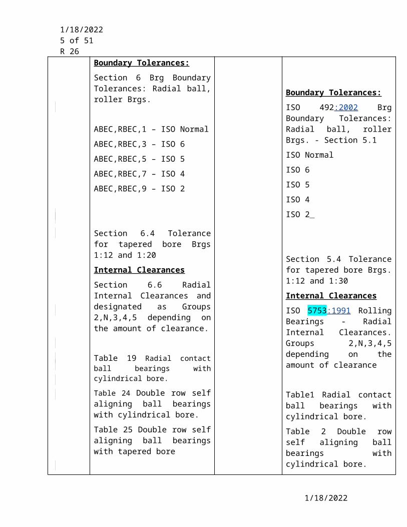
Boundary Tolerances:
Section 6 Brg Boundary Tolerances: Radial ball, roller Brgs.
ABEC,RBEC,1 – ISO Normal
ABEC,RBEC,3 – ISO 6
ABEC,RBEC,5 – ISO 5
ABEC,RBEC,7 – ISO 4
ABEC,RBEC,9 – ISO 2
For tapered roller bearings see ISO 355:1997 below.
For thrust bearings see ISO 104 below.
Boundary Dimensions:
ISO 15:1998 Brg Boundary Dimensions: Radial ball, roller brgs.(Cylindrical & Spherical)
ISO 464:1995 Radial Brg with locating snap ring.
ISO 8443:1999 Radial Ball Brg. with flanged outer ring – Flange dimensions
ISO 582:1995 Rolling Brg chamfer dimen. Maxium Values – bearings and housings
Boundary Tolerances:
ISO 492:2002 Brg Boundary Tolerances: Radial ball, roller Brgs. - Section 5.1
ISO Normal
ISO 6
ISO 5
ISO 4
ISO 2
5/9/2023
5/9/2023 5 of 41R 26
Section 6.4 Tolerance for tapered bore Brgs 1:12 and 1:20
Internal Clearances
Section 6.6 Radial Internal Clearances and designated as Groups 2,N,3,4,5 depending on the amount of clearance.
Table 19 Radial contact ball bearings with cylindrical bore. Table 24 Double row self aligning ball bearings with cylindrical bore.
Table 25 Double row self aligning ball bearings with tapered bore
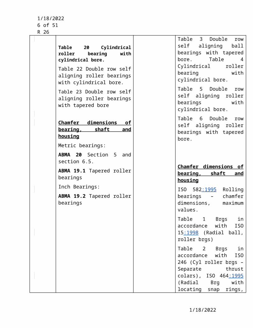
Table 20 Cylindrical roller bearing with cylindrical bore. Table 22 Double row self aligning roller bearings with cylindrical bore.
Table 23 Double row self aligning roller bearings with tapered bore
Chamfer dimensions of bearing, shaft and housing
Metric bearings:
ABMA 20 Section 5 and section 6.5.
ABMA 19.1 Tapered roller bearings
Inch Bearings:
ABMA 19.2 Tapered roller bearings
Section 5.4 Tolerance for tapered bore Brgs. 1:12 and 1:30
Internal Clearances
ISO 5753:1991 Rolling Bearings - Radial Internal Clearances. Groups 2,N,3,4,5 depending on the amount of clearance
Table1 Radial contact ball bearings with cylindrical bore.
Table 2 Double row self aligning ball bearings with cylindrical bore.
Table 3 Double row self aligning ball bearings with tapered bore. Table 4 Cylindrical roller bearing with cylindrical bore.
Table 5 Double row self aligning roller bearings with cylindrical bore.
Table 6 Double row self aligning roller bearings with tapered bore.
Chamfer dimensions of bearing, shaft and housing
ISO 582:1995 Rolling bearings – chamfer dimensions, maximum values.
Table 1 Brgs in accordance with ISO 15:1998 (Radial ball, roller brgs)
Table 2 Brgs in accordance with ISO 246 (Cyl roller brgs – Separate thrust colars), ISO 464:1995 (Radial Brg with
5/9/2023
5/9/2023 6 of 41R 26
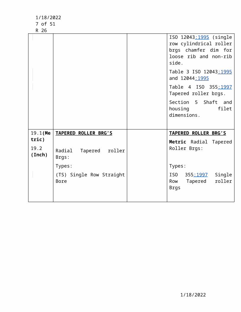
locating snap rings, ISO 12043:1995 (single row cylindrical roller brgs chamfer dim for loose rib and non-rib side.
Table 3 ISO 12043:1995 and 12044:1995
Table 4 ISO 355:1997 Tapered roller brgs.
Section 5 Shaft and housing filet dimensions.
19.1(Metric)
19.2 (Inch)
TAPERED ROLLER BRG’S
Radial Tapered roller Brgs:
Types:
(TS) Single Row Straight Bore
(TSF)Single Row Straight Bore Flanged Cup
TAPERED ROLLER BRG’S
Metric Radial Tapered Roller Brgs:
Types:
ISO 355:1997 Single Row Tapered roller Brgs
ISO 355:1997 Addendum 2: Single Row Tapered roller Brgs Flanges Cup
5/9/2023
5/9/2023 7 of 41R 26
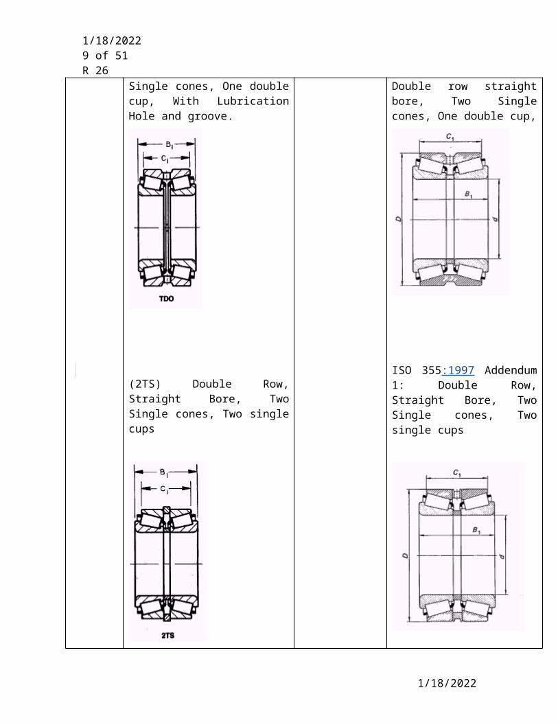
(TDO) Double row straight bore, Two Single cones, One double cup, With Lubrication Hole and groove.
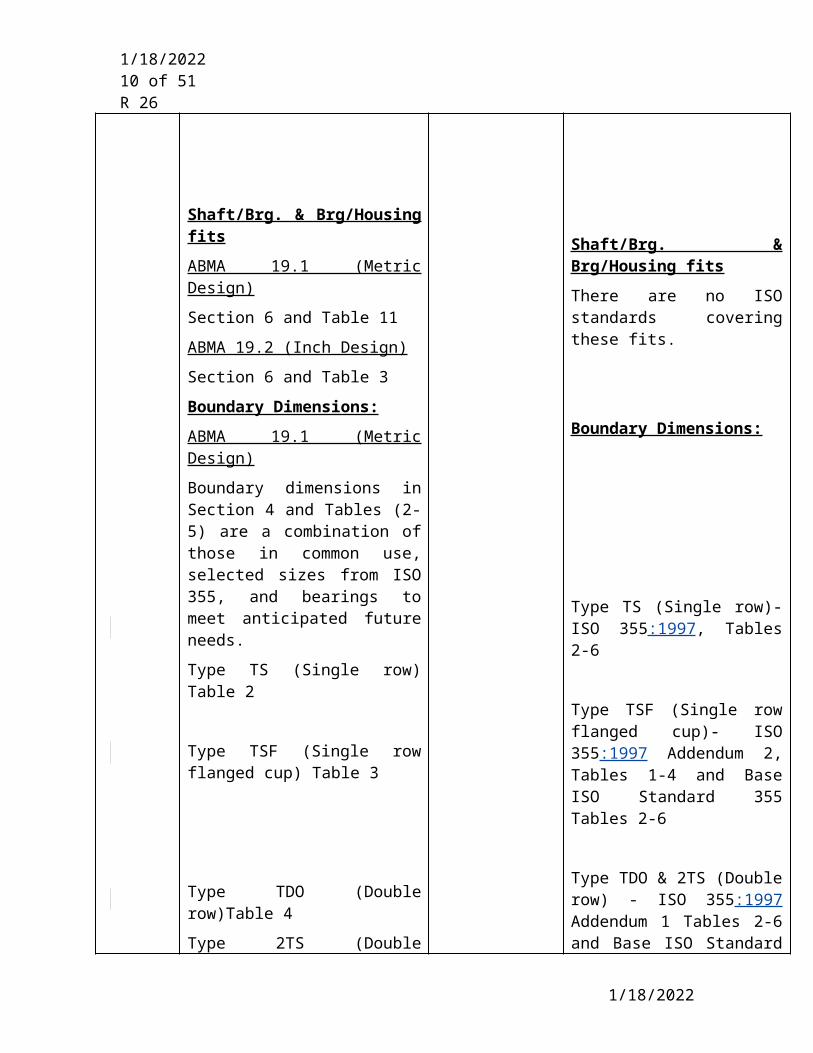
(2TS) Double Row, Straight Bore, Two Single cones, Two single cups
ISO 355:1997 Addendum 1:
Double row straight bore, Two Single cones, One double cup,
ISO 355:1997 Addendum 1: Double Row, Straight Bore, Two Single cones, Two single cups
5/9/2023

5/9/2023 8 of 41R 26
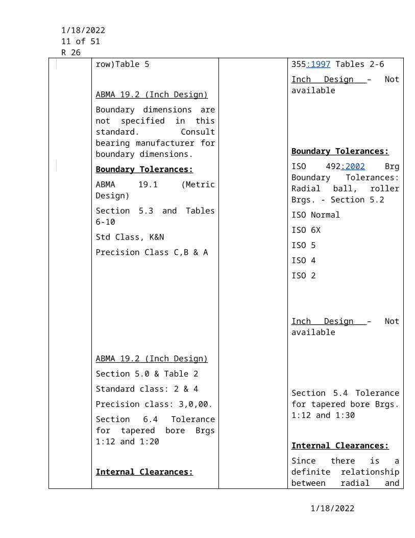
Shaft/Brg. & Brg/Housing fits
ABMA 19.1 (Metric Design)
Section 6 and Table 11
ABMA 19.2 (Inch Design)
Section 6 and Table 3
Boundary Dimensions:
ABMA 19.1 (Metric Design)
Boundary dimensions in Section 4 and Tables (2-5) are a combination of those in common use, selected sizes from ISO 355, and bearings to meet anticipated future needs.
Type TS (Single row) Table 2
Type TSF (Single row flanged cup) Table 3
Shaft/Brg. & Brg/Housing fits
There are no ISO standards covering these fits.
Boundary Dimensions:
Type TS (Single row)- ISO 355:1997, Tables 2-6
Type TSF (Single row flanged cup)- ISO 355:1997 Addendum 2, Tables 1-4 and Base ISO Standard 355 Tables 2-6
5/9/2023
5/9/2023 9 of 41R 26
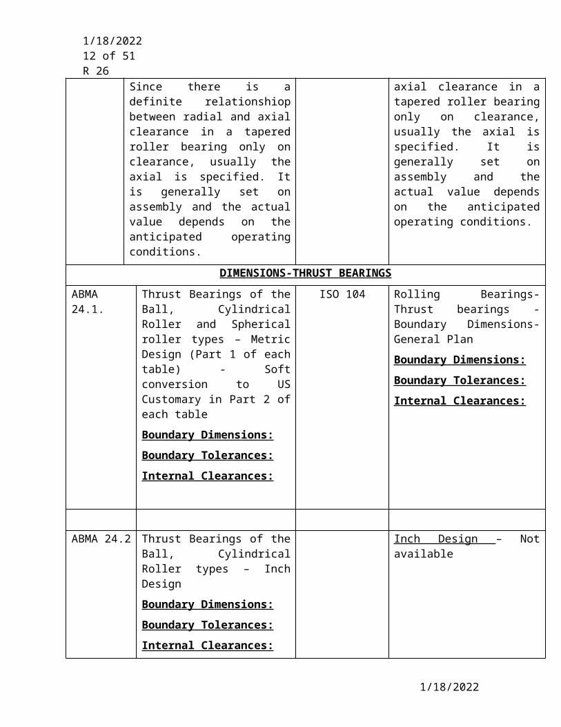
Type TDO (Double row)Table 4
Type 2TS (Double row)Table 5
ABMA 19.2 (Inch Design)
Boundary dimensions are not specified in this standard. Consult bearing manufacturer for boundary dimensions.
Boundary Tolerances:
ABMA 19.1 (Metric Design)
Section 5.3 and Tables 6-10
Std Class, K&N
Precision Class C,B & A
ABMA 19.2 (Inch Design)
Section 5.0 & Table 2
Standard class: 2 & 4
Precision class: 3,0,00.
Section 6.4 Tolerance for tapered bore Brgs 1:12 and 1:20
Internal Clearances:
Since there is a definite relationshiop between radial and axial clearance in a tapered roller bearing only on clearance, usually the axial is specified. It is generally set on assembly and the actual value depends on the anticipated operating conditions.
Type TDO & 2TS (Double row) - ISO 355:1997 Addendum 1 Tables 2-6 and Base ISO Standard 355:1997 Tables 2-6
Inch Design – Not available
Boundary Tolerances:
ISO 492:2002 Brg Boundary Tolerances: Radial ball, roller Brgs. - Section 5.2
ISO Normal
ISO 6X
ISO 5
ISO 4
ISO 2
Inch Design – Not available
Section 5.4 Tolerance for tapered bore Brgs. 1:12 and 1:30
Internal Clearances:
Since there is a definite relationship between radial and axial clearance in a tapered roller bearing only on clearance, usually the axial is specified. It is generally set on assembly and the actual value depends on the anticipated operating conditions.
DIMENSIONS-THRUST BEARINGS
5/9/2023
5/9/2023 10 of 41R 26
ABMA 24.1. Thrust Bearings of the Ball, Cylindrical Roller and Spherical roller types – Metric Design (Part 1 of each table) - Soft conversion to US Customary in Part 2 of each table
Boundary Dimensions:
Boundary Tolerances:
Internal Clearances:
ISO 104 Rolling Bearings-Thrust bearings - Boundary Dimensions-General Plan
Boundary Dimensions:
Boundary Tolerances:
Internal Clearances:
ABMA 24.2 Thrust Bearings of the Ball, Cylindrical Roller types – Inch Design
Boundary Dimensions:
Boundary Tolerances:
Internal Clearances:
Inch Design – Not available
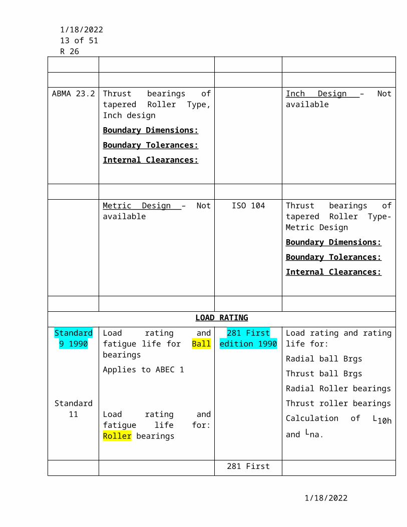
ABMA 23.2 Thrust bearings of tapered Roller Type, Inch design
Boundary Dimensions:
Boundary Tolerances:
Internal Clearances:
Inch Design – Not available
Metric Design – Not available ISO 104 Thrust bearings of tapered Roller Type- Metric Design
Boundary Dimensions:
Boundary Tolerances:
Internal Clearances:
LOAD RATING
5/9/2023
5/9/2023 11 of 41R 26
Standard 9 1990
Standard 11
Load rating and fatigue life for Ball bearings
Applies to ABEC 1
Load rating and fatigue life for: Roller bearings
281 First edition 1990
Load rating and rating life for:
Radial ball Brgs
Thrust ball Brgs
Radial Roller bearings
Thrust roller bearings
Calculation of L10h and Lna.
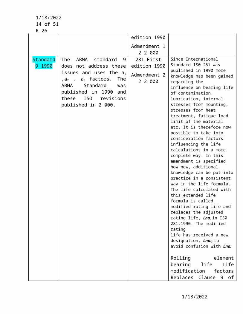
281 First edition 1990
Admendment 1 2 2 000
Standard 9 1990
The ABMA standard 9 does not address these issues and uses the a1 ,a2 , a3 factors. The ABMA Standard was published in 1990 and these ISO revisions published in 2 000.
281 First edition 1990
Admendment 2 2 2 000
Since International Standard IS0 281 was published in 1990 more knowledge has been gained regarding theinfluence on bearing life of contamination, lubrication, internal stresses from mounting, stresses from heattreatment, fatigue load limit of the material etc. It is therefore now possible to take into consideration factorsinfluencing the life calculations in a more complete way. In this amendment is specified how new, additional knowledge can be put into practice in a consistent way in the life formula. The life calculated with this extended lifeformula is called modified rating life and replaces the adjusted rating life, Lna, in IS0 281:1990. The modified ratinglife has received a new designation, Lnm, to avoid confusion with Lna.
Rolling element bearing life Life modification factors Replaces Clause 9 of 281:1990
5/9/2023
5/9/2023 12 of 41R 26
Replaces Lna Adjusted rating
life with the Modified rating life Lnm..Still does not give any number for modifying fators other than reliability.
15:1998 (Rolling bearings-Radial bearings-Boundary dimensions – General Plan)
12043:1995 Single row cylindrical roller bearings – chamfer dimensions for loose rib and non rib sides
12044:1995 Single row angular contact ball bearings- chamfer dimensions for outer ring non thrust side
6.9.2.1 Rolling element bearings shall be located, retained and mounted in accordance with the following: a. Bearings shall be located on the shaft using shoulders, collars or other positive locating devices; snap rings and spring-type washers are not acceptable.
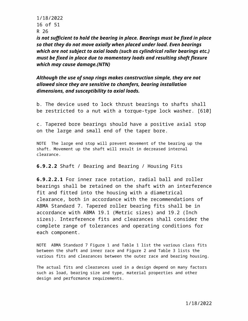
Discussion: Bearing location on shaft. When fixing a bearing in position on a shaft or housing, there are many instances where the interference fit alone is not sufficient to hold the bearing in place. Bearings must be fixed in place so that they do not move axially when placed under load. Even bearings which are not subject to axial loads (such as cylindrical roller bearings etc.) must be fixed in place due to momentary loads and resulting shaft flexure which may cause damage.(NTN)
Although the use of snap rings makes construction simple, they are not allowed since they are sensitive to chamfers, bearing installation dimensions, and susceptibility to axial loads.
b. The device used to lock thrust bearings to shafts shall be restricted to a nut with a torque-type lock washer. [610]
c. Tapered bore bearings should have a positive axial stop on the large and small end of the taper bore.
NOTE The large end stop will prevent movement of the bearing up the shaft. Movement up the shaft will result in decreased internal clearance.
6.9.2.2 Shaft / Bearing and Bearing / Housing Fits
5/9/2023
5/9/2023 13 of 41R 26
6.9.2.2.1 For inner race rotation, radial ball and roller bearings shall be retained on the shaft with an interference fit and fitted into the housing with a diametrical clearance, both in accordance with the recommendations of ABMA Standard 7. Tapered roller bearing fits shall be in accordance with ABMA 19.1 (Metric sizes) and 19.2 (Inch sizes). Interference fits and clearances shall consider the complete range of tolerances and operating conditions for each component.
NOTE ABMA Standard 7 Figure 1 and Table 1 list the various class fits between the shaft and inner race and Figure 2 and Table 3 lists the various fits and clearances between the outer race and bearing housing.
The actual fits and clearances used in a design depend on many factors such as load, bearing size and type, material properties and other design and performance requirements.
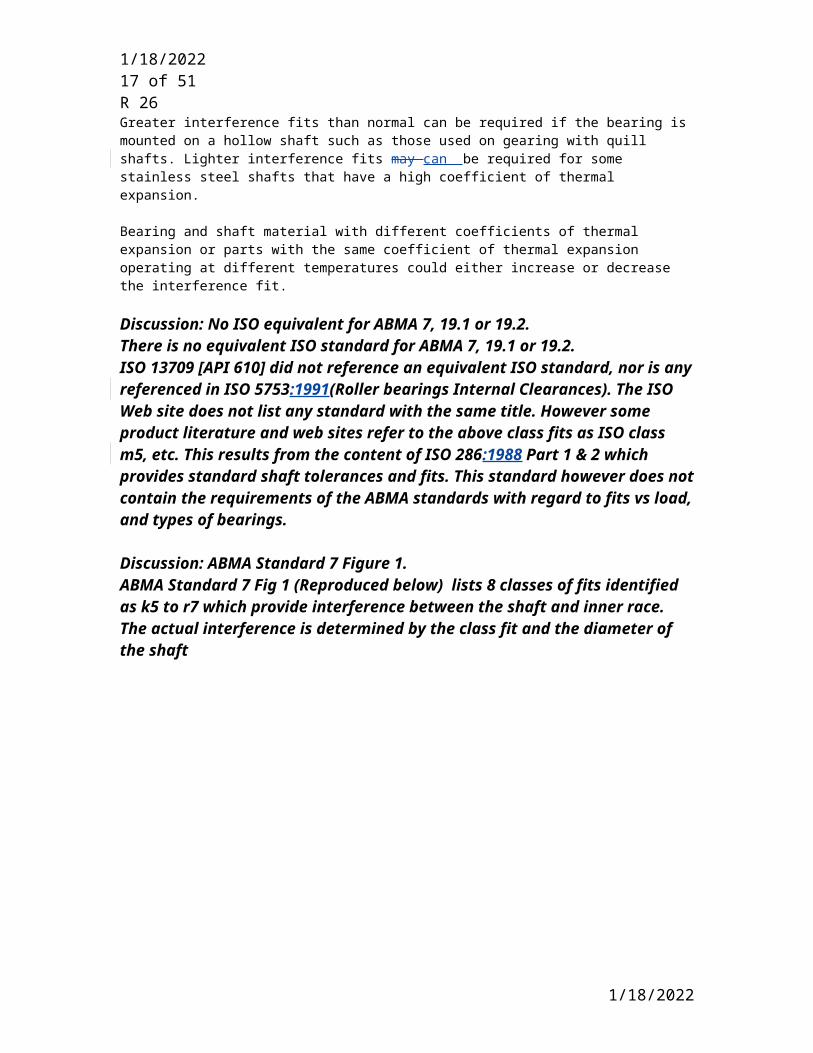
Greater interference fits than normal can be required if the bearing is mounted on a hollow shaft such as those used on gearing with quill shafts. Lighter interference fits may can be required for some stainless steel shafts that have a high coefficient of thermal expansion.
Bearing and shaft material with different coefficients of thermal expansion or parts with the same coefficient of thermal expansion operating at different temperatures could either increase or decrease the interference fit.
Discussion: No ISO equivalent for ABMA 7, 19.1 or 19.2.There is no equivalent ISO standard for ABMA 7, 19.1 or 19.2. ISO 13709 [API 610] did not reference an equivalent ISO standard, nor is any referenced in ISO 5753:1991(Roller bearings Internal Clearances). The ISO Web site does not list any standard with the same title. However some product literature and web sites refer to the above class fits as ISO class m5, etc. This results from the content of ISO 286:1988 Part 1 & 2 which provides standard shaft tolerances and fits. This standard however does not contain the requirements of the ABMA standards with regard to fits vs load, and types of bearings.
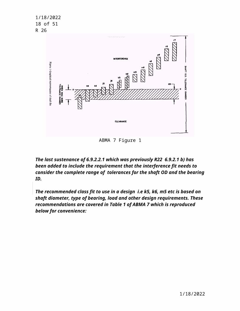
Discussion: ABMA Standard 7 Figure 1.ABMA Standard 7 Fig 1 (Reproduced below) lists 8 classes of fits identified as k5 to r7 which provide interference between the shaft and inner race. The actual interference is determined by the class fit and the diameter of the shaft
5/9/2023
5/9/2023 14 of 41R 26
ABMA 7 Figure 1
The last sustenance of 6.9.2.2.1 which was previously R22 6.9.2.1 b) has been added to include the requirement that the interference fit needs to consider the complete range of tolerances for the shaft OD and the bearing ID.
The recommended class fit to use in a design i.e k5, k6, m5 etc is based on shaft diameter, type of bearing, load and other design requirements. These recommendations are covered in Table 1 of ABMA 7 which is reproduced below for convenience:
5/9/2023

5/9/2023 15 of 41R 26
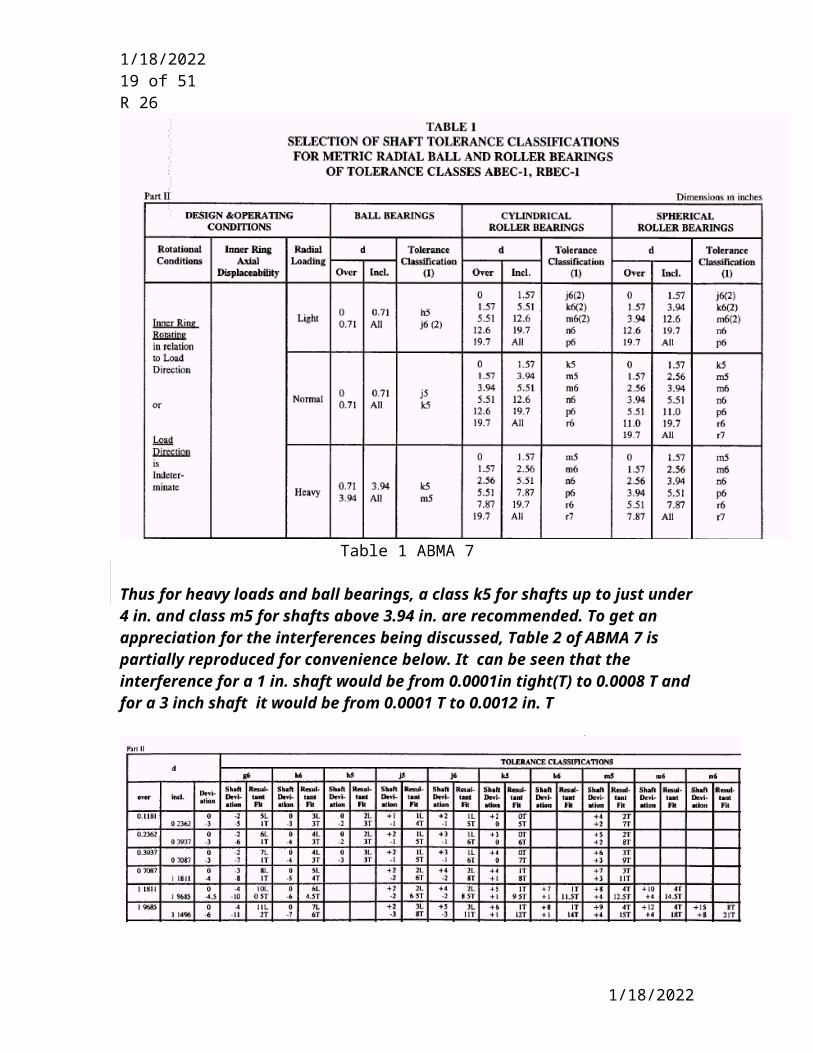
Table 1 ABMA 7
Thus for heavy loads and ball bearings, a class k5 for shafts up to just under 4 in. and class m5 for shafts above 3.94 in. are recommended. To get an appreciation for the interferences being discussed, Table 2 of ABMA 7 is partially reproduced for convenience below. It can be seen that the interference for a 1 in. shaft would be from 0.0001in tight(T) to 0.0008 T and for a 3 inch shaft it would be from 0.0001 T to 0.0012 in. T
Table 2 ABMA 7
5/9/2023
5/9/2023 16 of 41R 26
One of the rolling element bearing manufacturers recommends a k5 class fit for ball bearings 18-100 mm.
Discussion: ABMA 7, ISO 5753:1991 and ABMA 20. ABMA 7 (Shaft – Housing Fits) allows roller bearings of the Cylindrical AND Spherical design. It appears that in ISO 5753:1991 and ABMA 20 the cylindrical and spherical roller bearings are grouped together under roller bearings.
6.9.2.2.2 The vendor shall advise on the data sheets the interference fit between the shaft and the inner ring of the bearing and the clearance between the outer ring of the bearing and the housing used in the design.
NOTE This paragraph applies to all rolling element bearings, including both ball and roller types. For certain roller bearings, such as cylindrical roller types with separable races, bearing housing diametric clearance may not be appropriate. [This Note was previously a discussion paragraph but it was changed to a Note in API 610. Therefore it was made a Note in these SP]
Discussion: Describes reason for requirement.This information is required for inspection and subsequent rebuilding of the equipment.
6.9.2.2.3 Bearings shall be mounted directly on the shaft; bearing carriers (sleeves) are not acceptable.
Discussion: Describes reason for requirement.Bearing carriers and sleeves under the bearing result in additional interference fit considerations which can develop into improper internal bearing clearances. When mounting a bearing, the interference fit between the inner race and shaft, increases the inner race ID and subsequently reduces the bearing internal clearance. This affect is doubled when the bearing is mounted on a sleeve, and then the sleeve is mounted on the shaft. Note consider rewording considering the case of using tapered adapters.( tapered bore bearings)
------------------------------------------------------------------------------------------------------------6.9.2.3 Internal Bearing Clearances [ISO 5753:1991, ABMA Standard 20]
Discussion: Bearing internal clearanceBearing internal clearance (initial clearance) is the amount of internal clearance a bearing has before being installed on a shaft or in a housing.
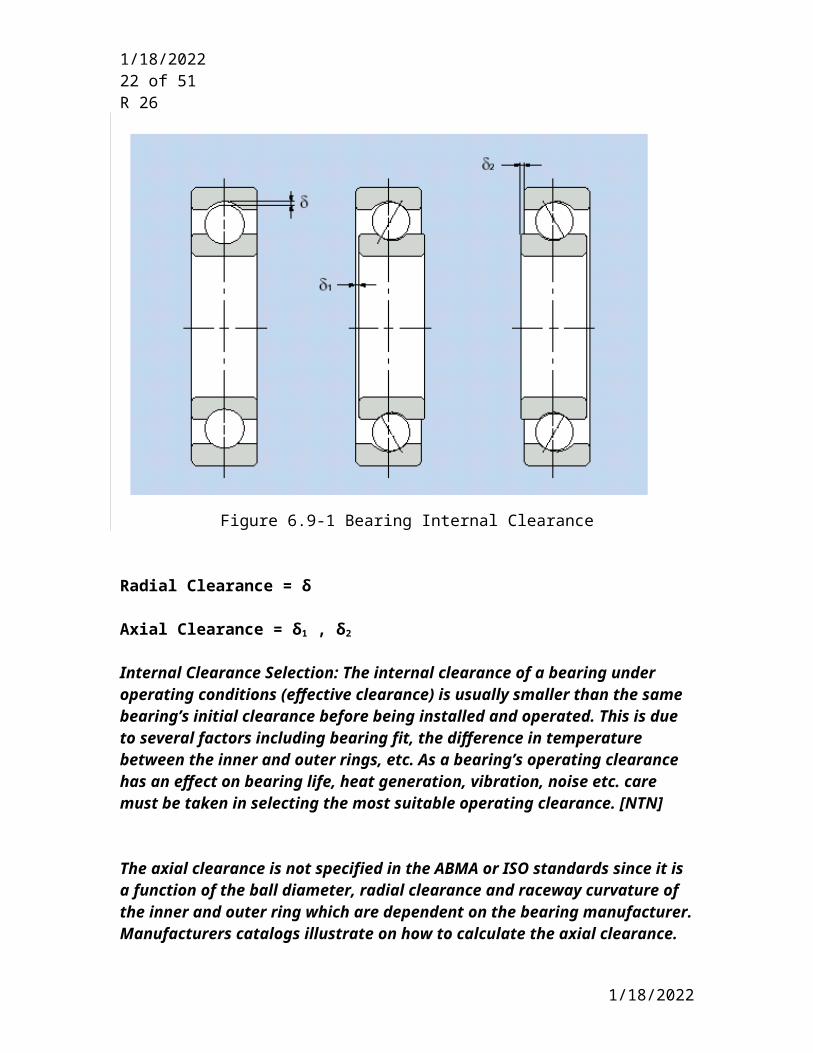
As shown in Fig. 6.9-1 when either the inner ring or the outer ring is fixed, and the other ring is free to move, displacement can take place in either an axial or radial direction. This amount of displacement (radial or axially) is termed the internal clerance and depending on the direction is called radial internal clearance or the axial internal clearance. [NTN]
5/9/2023
5/9/2023 17 of 41R 26
Discussion: Nomenclature.The race is the inside surface of the ring. [CPC]
Discussion: Figure 6.9-1Radial and Axial Clearance.
Figure 6.9-1 Bearing Internal Clearance
Radial Clearance = δ
Axial Clearance = δ1 , δ2
Internal Clearance Selection: The internal clearance of a bearing under operating conditions (effective clearance) is usually smaller than the same bearing’s initial clearance before being installed and operated. This is due to several factors including bearing fit, the difference in temperature between the inner and outer rings, etc. As a bearing’s operating clearance has an effect on bearing life, heat generation, vibration, noise etc. care must be taken in selecting the most suitable operating clearance. [NTN]
The axial clearance is not specified in the ABMA or ISO standards since it is a function of the ball diameter, radial clearance and raceway curvature of the inner and outer ring which are dependent on the bearing manufacturer. Manufacturers catalogs illustrate on how to calculate the axial clearance.
5/9/2023
5/9/2023 18 of 41R 26
Discussion: MEASURING MOUNTED CLEARANCESWhen measuring the mounted clearance of a bearing in a machine, allowances need to be made for the increased clearance due to the deflection of the rolling elements, the clearance between the outer race and the housing and the reduced internal bearing clearance due to expansion of the inner race when the bearing is shrunk onto the shaft.
Since the bearings have either point or line contact the contact stresses can be very high, and the elements can deflect depending on the lifting force exerted during the lift clearance check. For example, a 50mm (2 in.) bearing with a lift force of 5 kg (11 Lbs) can deflect the elements approximately 0.0002”. A C3 clearance for this bearing is in the range of 15-33 microns (0.0006 -0.0012”.) and this 0.0002”deflection needs to be subtracted from the measured reading.
When the bearing is shrunk on the shaft, the inner race expands which decreases the bearing internal clearance. The decrease in clearance due to the shrinking of the bearing on the shaft can range from approximately 70-90% of the effective interference.
The class fit between the outer race and the bearing housing will determine this clearance. This clearance needs to be subtracted from the lift check to determine the bearings internal clearance.
The mounted clearance is therefore different than the unmounted clearance. The machinery manufacturer should provide the procedure and value for this installed measurement. Note that ABMA 4 “Tolerance Deflections and Gageing Practices for Ball and Roller Bearings” provided procedures for measuring only UNMOUNTED bearing dimensions and not installed bearings.
Discussion: Additional Definitions.The following definitions were added as 3.56 & 3.57
3.56 Rolling element bearing effective clearance: The mounted bearings internal clearance under operating conditions.
3.57 Rolling Element bearing initial clearance: The bearings internal clearance before it is installed on a shaft or in a housing.
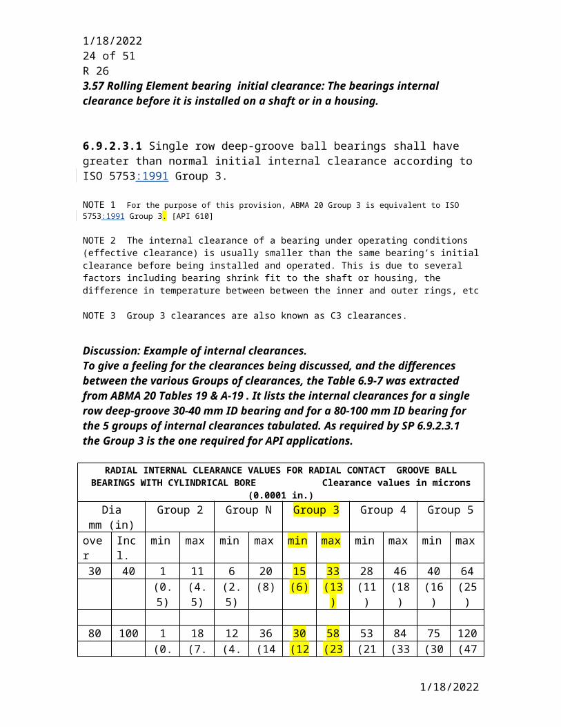
6.9.2.3.1 Single row deep-groove ball bearings shall have greater than normal initial internal clearance according to ISO 5753:1991 Group 3.
NOTE 1 For the purpose of this provision, ABMA 20 Group 3 is equivalent to ISO 5753:1991 Group 3. [API 610]
NOTE 2 The internal clearance of a bearing under operating conditions (effective clearance) is usually smaller than the same bearing’s initial clearance before being installed and operated. This is due to several
5/9/2023
5/9/2023 19 of 41R 26
factors including bearing shrink fit to the shaft or housing, the difference in temperature between between the inner and outer rings, etc
NOTE 3 Group 3 clearances are also known as C3 clearances.
Discussion: Example of internal clearances.To give a feeling for the clearances being discussed, and the differences between the various Groups of clearances, the Table 6.9-7 was extracted from ABMA 20 Tables 19 & A-19 . It lists the internal clearances for a single row deep-groove 30-40 mm ID bearing and for a 80-100 mm ID bearing for the 5 groups of internal clearances tabulated. As required by SP 6.9.2.3.1 the Group 3 is the one required for API applications.
RADIAL INTERNAL CLEARANCE VALUES FOR RADIAL CONTACT GROOVE BALL BEARINGS WITH CYLINDRICAL BORE Clearance values in microns (0.0001 in.)Dia
mm (in)Group 2 Group N Group 3 Group 4 Group 5
over Incl. min max min max min max min max min max30 40 1 11 6 20 15 33 28 46 40 64
(0.5) (4.5) (2.5) (8) (6) (13) (11) (18) (16) (25)
80 100 1 18 12 36 30 58 53 84 75 120(0.5) (7.0) (4.5) (14) (12) (23) (21) (33) (30) (47)
Table 6.9-7
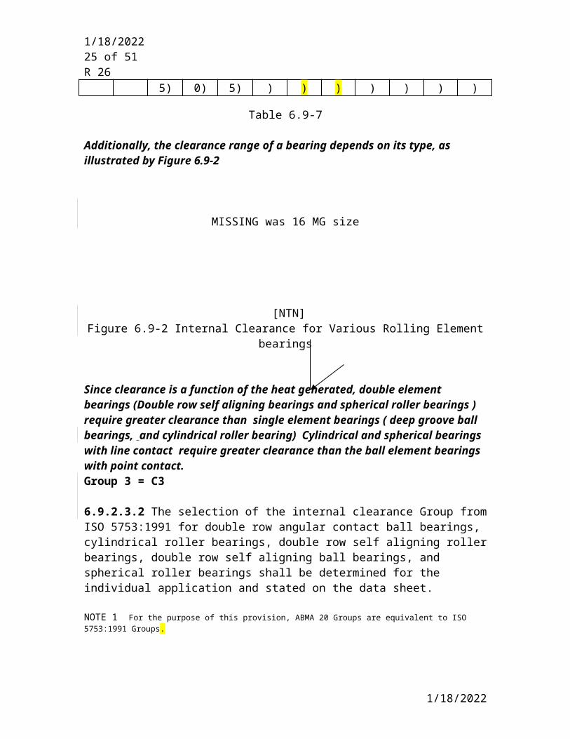
Additionally, the clearance range of a bearing depends on its type, as illustrated by Figure 6.9-2
MISSING was 16 MG size
[NTN]Figure 6.9-2 Internal Clearance for Various Rolling Element bearings
Since clearance is a function of the heat generated, double element bearings (Double row self aligning bearings and spherical roller bearings ) require greater clearance than single element bearings ( deep groove ball bearings, and cylindrical roller bearing) Cylindrical and spherical bearings with line contact require greater clearance than the ball element bearings with point contact.Group 3 = C3
5/9/2023

5/9/2023 20 of 41R 26
6.9.2.3.2 The selection of the internal clearance Group from ISO 5753:1991 for double row angular contact ball bearings, cylindrical roller bearings, double row self aligning roller bearings, double row self aligning ball bearings, and spherical roller bearings shall be determined for the individual application and stated on the data sheet.
NOTE 1 For the purpose of this provision, ABMA 20 Groups are equivalent to ISO 5753:1991 Groups.
NOTE 2 These clearances apply to non-preloaded bearings and of a design such that they can take purely radial load. [ISO 5753:1991]
NOTE 3 Single row tapered roller bearings and single row angular contact ball bearing mounted back-to-back or face-to-face clearance are not covered in ISO 5753:1991 and ABMA 20 since clearances for these bearings are set during assembly in the machine,
6.9.2.3.3 Preload for angular contact ball bearings, and taper roller bearings shall be determined for the individual application, and stated on the data sheet. Preload shall be set by grinding of the race faces rather than by spacers or springs.
NOTE Preload of angular contact ball bearings, and tapered roller bearings, is set during the installation of the bearing in the machine. The faces of these bearings are ground by the bearing manufacturer during manufacturing so as to result in the specified preload when finally assembled in the back-to-back or face to face configuration in the machine.
Discussion: Preload
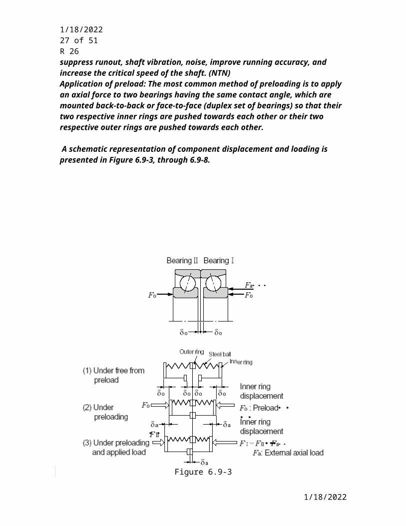
Preload : The compressive force acting on a rolling element bearing when the bearing has zero internal clearance. Normally bearings are used with a slight internal clearance under operating conditions as required by paragraph 6.9.2.3.2 and 6.9.2.3.3. However, in some applications, the bearings internal clearance is removed, in fact it is negative i.e the races, and rolling elements are in compression before operation. This is analogous to a spring that is compressed between your right and left hand. Once the spring is compressed, your hands are preloaded against each other. (NTN) Axial preload is applied most commonly to angular contact ball bearings and tapered roller bearingsPurpose of preload: The primary reason for providing a preloaded bearing is to prevent unloading and skidding of an inactive lightly loaded bearing. Giving preload to bearings results in the rolling element and raceway surfaces being under constant elastic compressive forces at their contact points. This has the effect of making the bearing extremely rigid so that even when load is applied to the bearing, radial or axial shaft displacement does not occur. In addition to preventing skidding, preload may be used to suppress runout, shaft vibration, noise, improve running accuracy, and increase the critical speed of the shaft. (NTN)Application of preload: The most common method of preloading is to apply an axial force to two bearings having the same contact angle, which are mounted back-to-back or face-to-face (duplex set of bearings) so that their two respective inner rings are pushed towards each other or their two respective outer rings are pushed towards each other.
5/9/2023
5/9/2023 21 of 41R 26
A schematic representation of component displacement and loading is presented in Figure 6.9-3, through 6.9-8.
Figure 6.9-3
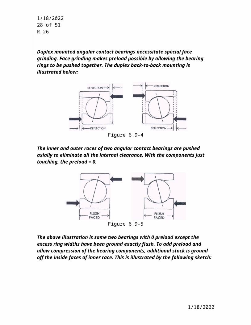
Duplex mounted angular contact bearings necessitate special face grinding. Face grinding makes preload possible by allowing the bearing rings to be pushed together. The duplex back-to-back mounting is illustrated below:
5/9/2023
5/9/2023 22 of 41R 26
Figure 6.9-4
The inner and outer races of two angular contact bearings are pushed axially to eliminate all the internal clearance. With the components just touching, the preload = 0.
Figure 6.9-5
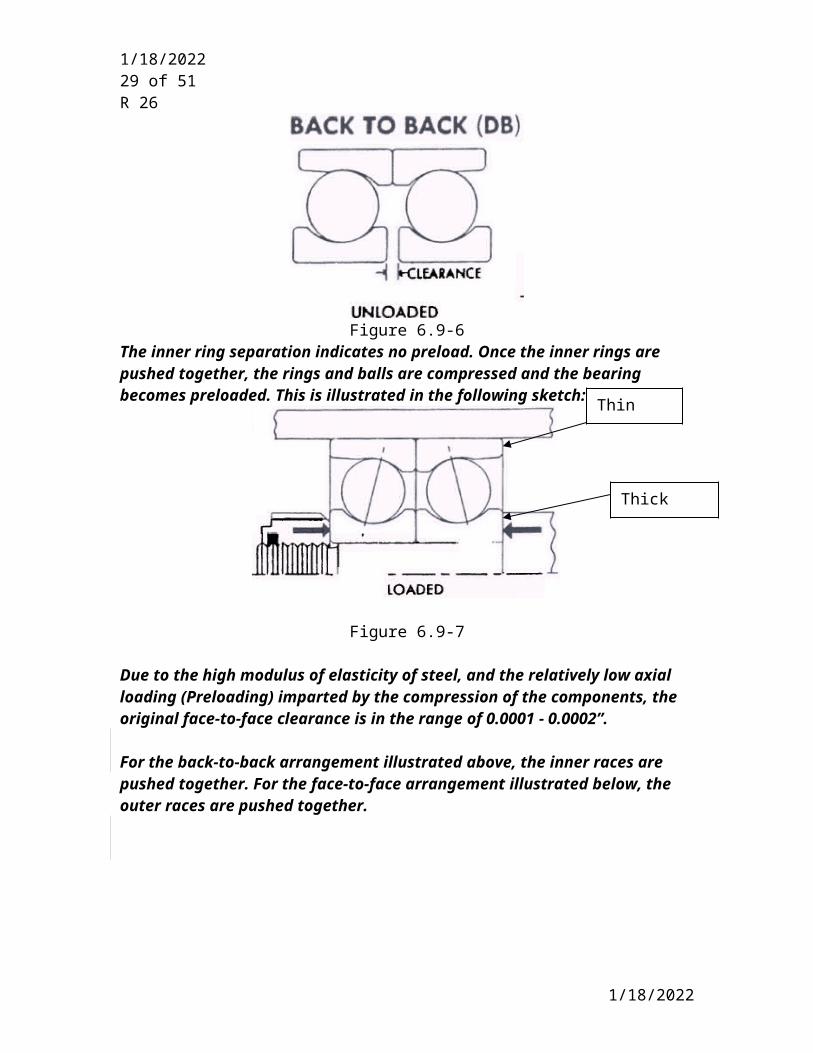
The above illustration is same two bearings with 0 preload except the excess ring widths have been ground exactly flush. To add preload and allow compression of the bearing components, additional stock is ground off the inside faces of inner race. This is illustrated by the following sketch:
Figure 6.9-6The inner ring separation indicates no preload. Once the inner rings are pushed together, the rings and balls are compressed and the bearing becomes preloaded. This is illustrated in the following sketch:
5/9/2023
Thin Face

5/9/2023 23 of 41R 26
Figure 6.9-7
Due to the high modulus of elasticity of steel, and the relatively low axial loading (Preloading) imparted by the compression of the components, the original face-to-face clearance is in the range of 0.0001 - 0.0002”.
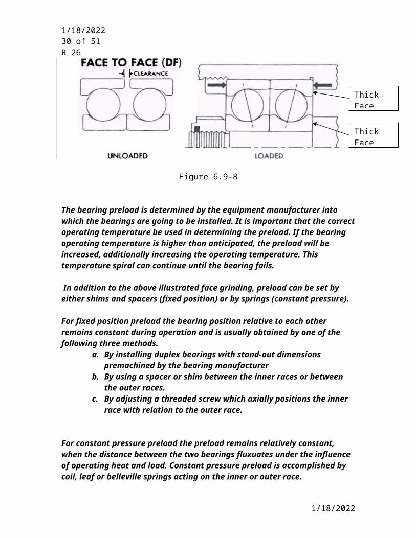
For the back-to-back arrangement illustrated above, the inner races are pushed together. For the face-to-face arrangement illustrated below, the outer races are pushed together.
Figure 6.9-8
The bearing preload is determined by the equipment manufacturer into which the bearings are going to be installed. It is important that the correct operating temperature be used in determining the preload. If the bearing operating temperature is higher than anticipated, the preload will be increased, additionally increasing the operating temperature. This temperature spiral can continue until the bearing fails.
In addition to the above illustrated face grinding, preload can be set by either shims and spacers (fixed position) or by springs (constant pressure).
5/9/2023
Thick Face
Thick Face
Thick Face
5/9/2023 24 of 41R 26
For fixed position preload the bearing position relative to each other remains constant during operation and is usually obtained by one of the following three methods.
a. By installing duplex bearings with stand-out dimensions premachined by the bearing manufacturer
b. By using a spacer or shim between the inner races or between the outer races.
c. By adjusting a threaded screw which axially positions the inner race with relation to the outer race.
For constant pressure preload the preload remains relatively constant, when the distance between the two bearings fluxuates under the influence of operating heat and load. Constant pressure preload is accomplished by coil, leaf or belleville springs acting on the inner or outer race.
Generally about 95% of the API pumps do not require preload and the preload is accomplished by the fixed preload method by requiring the bearing manufacturer to premachine the races faces. The use of spacers at the inner race or inner and outer race is not allowed in 6.9.2.3.3 since they can be easily improperly installed or lost. A very small percentage of pumps have constant pressure preload and this is accomplished by belleville springs.
Preload is calculated and specified as a force. The force required to compress the bearing to remove the axial race face clearance is the bearing preload. The amount of preload is determined by this initial gap. The larger the gap, the more compression is required to close it and thus the higher preload. In all cases, the gap is reduced to zero when mounting for all amounts of preload. For increased preload additional material is removed to increase the axial race face clearance.
6.9.2.4 Rolling Element Bearing Cages
6.9.2.4.1 Unless otherwise specified, double row or single row angular contact ball bearings and two single row ball bearings mounted back-to-back , face-to-face or tandem shall be provided with machined cages.
Discussion: Reason for requirement.The experience of the 610 ISO 13709 Joint working group is that machined brass or bronze cages are required for angular contact ball bearings.(Series 7000). Max speed - machined better, probably more difficult from lubrication stand point, machined brass may not be available, heat transfer better with brass, cages are used in lighter loaded, vibration less for machined cages.
6.9.2.4.2 Non-metallic cages shall not be used. [610]
Discussion: Reason for requirement.
5/9/2023
5/9/2023 25 of 41R 26
Non metallic cages are easily damaged if excessive heat is used to mount and dismount the bearing also Non-metallic cages also tend to give no warning of trouble and therefore fail “suddenly”. With oil lubrication, additives contained in the oil may lead to a reduction of the cage service life. [FAG]
5/9/2023

5/9/2023 26 of 41R 26
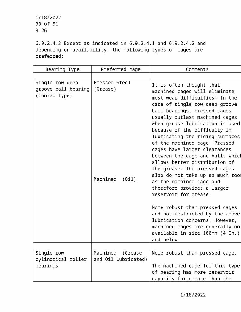
6.9.2.4.3 Except as indicated in 6.9.2.4.1 and 6.9.2.4.2 and depending on availability, the following types of cages are preferred:
Bearing Type Preferred cage Comments
Single row deep groove ball bearing (Conrad Type)
Pressed Steel (Grease)
Machined (Oil)
It is often thought that machined cages will eliminate most wear difficulties. In the case of single row deep groove ball bearings, pressed cages usually outlast machined cages when grease lubrication is used because of the difficulty in lubricating the riding surfaces of the machined cage. Pressed cages have larger clearances between the cage and balls which allows better distribution of the grease. The pressed cages also do not take up as much room as the machined cage and therefore provides a larger reservoir for grease.
More robust than pressed cages and not restricted by the above lubrication concerns. However, machined cages are generally not available in size 100mm (4 In.) and below.
Single row cylindrical roller bearings
Machined (Grease and Oil Lubricated)
More robust than pressed cage.
The machined cage for this type of bearing has more reservoir capacity for grease than the Single row deep groove bearing and is adequate to supply the required grease lubricant.
Double row spherical roller bearing
Machined (Grease and Oil Lubricated)
More robust than pressed cage.
The machined cage for this type of bearing has more reservoir capacity for grease than the Single row deep groove bearing and is adequate to supply the required grease lubricant.
Tapered roller bearings Pressed Steel (Grease and Oil Lubricated)
Manufacturers only make pressed gages for this type of bearing.
5/9/2023
5/9/2023 27 of 41R 26
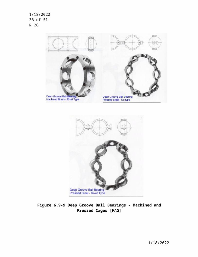
Discussion : Cage Function & Materials
Cage Function: The function of the cage is to keep the bearing elements apart so they do not rub against each other so as to keep friction and heat at a minimum, to keep them evenly spaced for uniform load distribution, guide the elements in the unloaded zone of the bearing, and prevent the elements from falling out of separable bearings.Transmission of forces is not one of the functions of the cage. [FAG]
Cage Materials:Bearing cage materials must have the strength to withstand rotational vibrations and shock loads. These materials must also have a low friction coefficient, be light weight, and be able to withstand bearing operation temperatures. [NTN]
Bearing cages are either machined, pressed or injection molded. Machined cages are made of brass or steel. Pressed cages are made of brass, hot, cold rolled or stainless steels. Injection molded cages are made of various types of plastics or PEEK material. Nonmetllic cages have a lower operating temperature limit than metallic cages. One manufacturer limits the outer race operating temperature to 100 C (212 F) when cages are non metallic. Pressed metallic cages are sensitive to operation above ndm of 250 000. [SKF]
For special applications such as for aircraft engine bearings, cages may be tensile brass, midcarbon nickel, chrome, or molybdenum steel is used after undergoing various heat treatments and high temperature tempering. The sliding properties of these materials may also be enhanced when silver plated. [NTN]
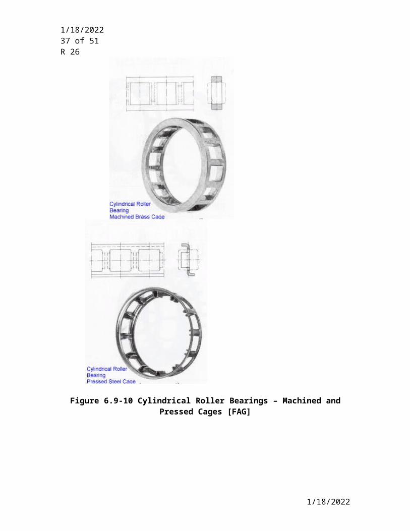
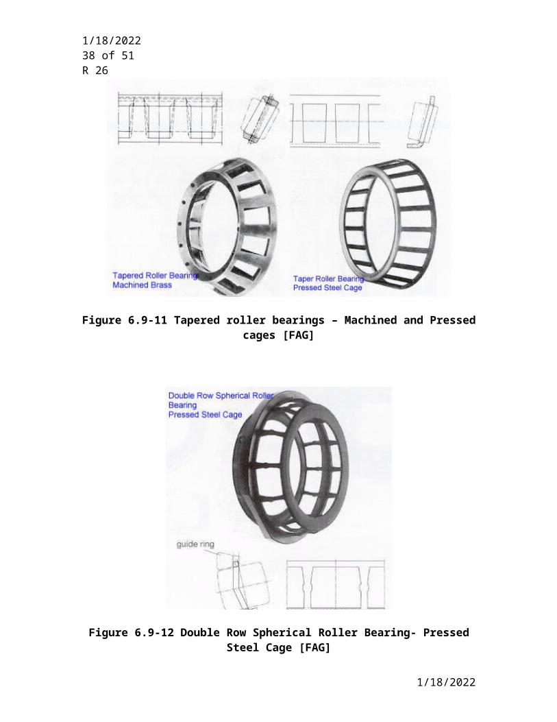
Discussion: Illustrations of various types of cagesFigures 6.9-9 to 6.9-13 illustrate various types of cage construction for the different types of bearings.
5/9/2023
5/9/2023 28 of 41R 26
5/9/2023
5/9/2023 29 of 41R 26
Figure 6.9-9 Deep Groove Ball Bearings – Machined and Pressed Cages [FAG]
5/9/2023
5/9/2023 30 of 41R 26
Figure 6.9-10 Cylindrical Roller Bearings – Machined and Pressed Cages [FAG]
5/9/2023

5/9/2023 31 of 41R 26
Figure 6.9-11 Tapered roller bearings – Machined and Pressed cages [FAG]
Figure 6.9-12 Double Row Spherical Roller Bearing- Pressed Steel Cage [FAG]
5/9/2023
5/9/2023 32 of 41R 26
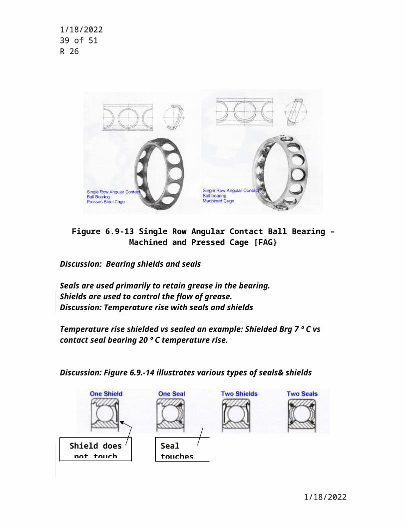
Figure 6.9-13 Single Row Angular Contact Ball Bearing – Machined and Pressed Cage [FAG}
Discussion: Bearing shields and seals
Seals are used primarily to retain grease in the bearing. Shields are used to control the flow of grease. Discussion: Temperature rise with seals and shields
Temperature rise shielded vs sealed an example: Shielded Brg 7 º C vs contact seal bearing 20 º C temperature rise.
Discussion: Figure 6.9.-14 illustrates various types of seals& shields
Figure 6.9-14 Schematics of Shields and Seals
Discussion: Sealed for life bearings Grease lubricated bearings supplied with seals may be referred to as “sealed for life” bearings. This life is dependent on the grease life rather than the 50 000 Hour bearing life requirement. This grease life is a strong function of the operating temperature. The
5/9/2023
Shield does not touch race
Seal touches race
5/9/2023 33 of 41R 26
catalog values for SKF is based on lithium base grease at 70º C. An increase in 15 ºC will reduce the grease life by half.
Discussion: Relubrication of greased bearings
The length of time during which a grease lubricated bearing will function satisfactorily without relubrication depends on the type of bearing, bearing size, load, speed, and operating temperature. Regreasing intervals can be obtained from bearing vender literature. The following is an excerpt from SKF catalogue “Bearing Installation and Maintenance Guide Publication 140-710 Pg 76. Each bearing manufacturer has developed criteria for regreasing of their bearings and the specific bearing manufacturers’ recommendations should be followed. i.e. this chart is only applicable to SKF bearings. Individual bearing manufacturers regreasing intervals can differ by a factor of 2. Other manufacturers such as NTN factor in bearing load and operation above 80 C.
For a 100 mm diameter bearing running at 3600 r/min the regreasing interval recommendation depends on the type of bearing.A – radial ball bearing = 300 Hrs.B – Cylindrical and needle roller bearing= 150 Hrs.C – Other bearings as describes = 30 Hrs.
5/9/2023

5/9/2023 34 of 41R 26
Regreasing can be performed by installing the bearing with no seals or shields and inserting grease into the bearing cavity through the grease supply fitting. The grease supply and drain may be on the same side of the bearing or on opposite sides of the bearing.
Shielded bearings are sometimes used in motors. For that application, there’s not unanimous agreement on the arrangement of the shields. H. Block in “Practical Lubrication for Industrial Facilities” pg 346 indicates one user prefers the shield to face the grease supply. The shield serves as a baffle and the shield - to-inner-ring annulus serves as a metering device to control grease flow.
Some motor manufacturers favor a double-shielded design which has been prelubricated. Packing the housing with grease next to the bearing prevents dirt and moisture from entering the bearing. Oil from this grease reservoir seeps into the bearing and revitalizes the grease within the bearing. A grease retainer labyrinth located on the inner side of the bearing is designed to prevent grease from reaching the motor winding.
A bearing with seals will leak more grease than a shielded bearing. There is more heat buildup in the sealed bearing, due to the rubbing seals, with subsequent reduction in grease viscosity and generation of internal pressure. This will force grease out between the seal and inner ring.
Sealed bearings are typically not used on API 610 Pumps.
Oil mist and ring lubricated bearings should not be supplied with seals or shields.
Polyeura, in motors - Don’t want to mix lubricants. Should have compatable greases for a train of equipment which needs to be regreased.Don’t want EP additives in the grease.
Greases are specified by an ISO number which indaicates the viscosity of the oil in the grease, and NLGI which indicates the “stiffness of the grease’.Revisit the highlighted topics when lubrication section is reviewed.
6.9.2.5 Bearing Boundary Dimensions [ABMA Standard 20, ISO 492:2002]
6.9.2.5.1 Radial ball and roller (cylindrical and spherical) bearing boundary dimensions shall be in accordance with ISO 15:1998 and ISO 582:1995. Tapered roller bearing boundary dimensions shall be in accordance with ISO 355:19 NOTE -97
NOTE For the purpose of this provision, ABMA 20 Section 2.0 and Section 5 are equivalent to ISO 15:1998 and ISO 582:1995 and ABMA 19.1 and ABMA 19.2 are equivalent to ISO 355:1997.
5/9/2023

5/9/2023 35 of 41R 26
Discussion: Explanation of NoteReferring to Table 6.9-6, ABMA 20 has several sections on bearing boundary dimensions covering various types of bearing configurations. Sections 2 & 5 as referenced in the note are the only ones applicable. Section 3 covers radial bearings with locating snap rings which are not allowed per SP 6.9.2.1.a, and Section 4 covers bearings with flanged outer ring.
Discussion: Reason for requirement.Boundary dimensions have been standardized in order to allow bearing interchangeability. The listing of “standard” size bearing is extensive. The dimensions describing the bearing envelope i.e bearing bores, bearing OD’s and bearing widths have all been standardized and can be found in ABMA 20. ABMA 20 lists 86 different bearing bore diameters from 0.6 to 2000 mm, 8 different bearing ODs and 9 different bearing widths. All standardized combinations of these dimensions are presented Table 1 of ABMA 20.
6.9.2.5.2 Radial ball and roller (cylindrical and spherical) bearing boundary tolerance class shall be in accordance with ISO 492:2002 Section 5.1 Normal tolerance class. Tapered roller bearing boundary tolerance shall be in accordance with ISO 492:2002 Section 5.2 Normal tolerance class.
NOTE 1 For the purpose of this provision, ABMA 20 Section 6-ABEC 1 (Ball bearings) and RBEC 1 (roller bearings) are equivalent to ISO 492:2002 Section 5.1Normal tolerance class.
NOTE 2 ABMA 19.1 Class K and 19.2 are equivalent to ISO 492:2002 Section 5.2 Normal tolerance class.
Discussion: Reason for requirement.Paragraph 6.9.2.5.2 was added since there was no tolerance on bearing boundary dimensions.
ABMA Standard 7 as required by 6.9.2.5.1 covers the general selection of shaft and housing fits ( i.e. interference or clearance fits) for metric radial ball and roller bearings (cylindrical & spherical). Since the amount of interference or clearance depends on the tolerances of the mating dimensions, a tolerance has to be applied to these boundary dimensions. ABMA 20 specified that bearings be manufactured in accordance with tolerance classes as describe as ABEC 1 or RBEC 1. These tolerances apply only to the bearings mounting dimensions and not any internal components such as the balls, rollers or races.
ABEC stands for Annular Bearing Engineering Committee (not American or Antifriction Bearing Engineering Committee) and refers to ball bearing tolerances.
RBEC refers to roller bearing tolerance and stands for Roller bearing Engineering Committee )
5/9/2023
5/9/2023 36 of 41R 26
A listing of these BOUNDARY tolerance (ABEC 1) can be found in ABMA Standard 20 and ISO 492:2002.
Discussion: ABMA & ISO Classes of Boundary tolerancesRolling element bearing manufacturing BOUNDARY tolerances are divided into 5 classes. A listing of these classes and the corresponding ABMA and ISO designations are listed in table 6.9-8
Tolerance Classes (From ABMA 20 para 6.3)
ABMA 20 Class ISO 492:2002
ClassABEC 1, RBEC 1 NormalABEC 3, RBEC 3 6ABEC 5, RBEC 5 5ABEC 7, RBEC 7 4ABEC 9, RBEC 9 2
Table 6.9-8 Tolerance Class
Airframe bearings, instrument ball bearings, needle roller bearings, tapered roller bearings and thrust bearings and other bearing types and series not conforming to the requirements in ABMA 20 are covered in other ABMA Standards.
The tolerances in ISO 492:2002 & ABMA 20 apply to the inner ring ID and width and outer ring OD and width and not to the OD of the inner ring nor the ID of the outer ring or the balls or rollers. The tolerances in ISO 492 & ABMA 20 thus only apply to the mounting dimensions and runouts.
Discussion: Examples of bearing tolerancesWhat are the actual tolerances required by the ABEC, RBEC or ISO designation? A comparison of the tolerance for a 30-50 mm ID bore bearing for the inner and outer ring and the various classes is presented in Table 6.9-9. The highlighted ABEC 1, RBEC 1 ISO Normal class is the specified requirement in 6.9.2.5.2
Bearing size (30-50 mm Bearing Bore) From ABMA 20Tolerance Class Inner Ring Outer Ring
5/9/2023
5/9/2023 37 of 41R 26
ABMA 20 Class ISO 5753:1991
Class
ID (Bore of Bearing)
Variation of mean bore dia.(Vdmp )
Microns 0(.0001 in.)
ODVariation of mean
outside dia. (VDmp )
Microns (0.0001 in)
ABEC 1, RBEC 1 Normal 9 (3.5) 8 (3.0)ABEC 3, RBEC 3 6 8 (3.0) 7 (3.0)ABEC 5, RBEC 5 5 4 (1.5) 4 (1.5)ABEC 7, RBEC 7 4 3 (1.0) 3 (1.0)ABEC 9, RBEC 9 2 1.5 (0.5) 2 (1.0)
Table 6.9-9 ABEC & RBEC Tolerance for 30-50 mm Bearing Bore
Discussion: Bearing manufacturers tolerancesSome bearing manufacturers supply, as standard, bearings to a higher tolerance such as ISO 6 (ABEC 3). Since the API standards are a minimum standard, these tighter tolerance bearings meet the requirements of 6.9.2.5.2.
6.9.2.5.3 Bearing chamfers shall conform to ISO 582:1995 and ABMA 19.2
NOTE For the purpose of this provision ABMA 20 and ABMA 19.1 are equivalent to ISO 582.
Discussion: Reason for referencing ABMA 19.2ABMA 19.2 is the inch series for tapered roller bearings and there is no ISO equivalent.
Discussion: Reason for requirement. In addition to the boundary dimensions and tolerances, rolling element bearing chamfers on the outside corners of the OD and ID races and the mating components have been standardized. Standardization eliminates the possibility of stress risers developing when the radius or chamfer on the bearing is smaller than on the mating component.
Discussion: Shaft filets. Paragraph 6.6.7 in the shafting section of standard paragraphs has been added to cover the filets on shaft shoulders against which rolling element bearings seat.
6.9.2.5.4 Finished steel balls for rolling element bearings shall be in accordance with ISO 3290:2001 with a maximum of Grade 16.
Discussion: Reason for requirement.ISO 3290 is the only standard we have found which addresses the internal configuration of a rolling element bearing.
5/9/2023
5/9/2023 38 of 41R 26
Discussion: Content of ISO 3290:2001. ISO 3290:2001 lists standard size balls, form, surface roughness tolerance, and sorting tolerance and gages. The ball grade, as identified by the letter G, is a specific combination of dimensional, form, surface roughness and sorting tolerances for the balls. Sorting tolerance and gage grades go from G3, the most stringent, to G 200 the least stringent.
Discussion: AFBMA STD 10. AFBMA STD 10 previously covered the same subject but the AFBMA standard has been superseded by ISO 3290:2001.
6.9.2.6 Rolling element thrust bearings shall be selected in accordance with the following:
a. A rolling element bearing may be a single-row deep-groove ball bearing provided the combined axial thrust and radial load is within the capability of such a bearing and requirements of 6.9.1 are satisfied.
Note to TF Chairs: Only include this paragraph if the equipment covered by your specification generates very light axial loads since the deep groove 6 000 series ball bearings have very limited axial load carrying capacity.
Discussion: API 610 Experience.This single row deep groove option has been eliminated from 610 as a thrust bearing and used only as a radial bearing (see 610 9th edition para 5.10.1.4. and 5.10.1.5) since pumps generally have axial loads which exceed the capability of the 6 000 series deep groove ball bearings.
b. Where the loads exceed the capability of a single-row deep-groove bearing, a matched pair of single-row, 40° angular contact type (7 000 series) bearings shall be used. Unless otherwise specified, bearings shall be mounted in a paired arrangement back-to-back. The need for preload shall be determined by the vendor to suit the application and meet the bearing life requirements of 6.9.1.3.[677]
Discussion: Reason for 40°contact angle. These 7 000 series bearings come in various contact angles such as 25 º, 30º, and 40º. The higher the angle, the larger the thrust capacity of the bearing. Mandating the highest contact angle provides bearings with the highest thrust load carrying capability, thus reducing spare parts inventory. With less spare parts, the possibility of inadvertently installing a lower thrust capability bearings on rework is also reduced. There are no mounting dimensional differences between the same “size” bearings with different contact angles.
Discussion: Reason for preload determination. With the back-to-back arrangement one set of balls will be thrust loaded the other will be unloaded. Unloaded balls can skid, thus the need to determine if preload is
5/9/2023
5/9/2023 39 of 41R 26
necessary. For a discussion on preload refer to the discussion paragraphs after 6.9.2.3.3
Discussion: Pump Pac SKF bearings.One manufacturer sells a back-to back bearing set which does not comply with this requirement and it is marketed as a “high thrust load” bearing . One of the bearings has a 40º contact angle and the other bearing in the back-to-back pair has a 15º contact angle. It is easy to install these bearings in incorrectly with the low thrust 15º contact angle side actually handling the high thrust load. This can lead to premature failure. The advantage of this bearing is that the 15º contact angle bearing on the lightly loaded side has less of a tendency to skid than if it were 40º with no preload. The thrust capability of a 40 º bearing is 25% greater than a 15º bearing. Discussion:Reason for Back-to-back requirement. Angular contact bearings can be installed back-to-back ,face-to face or in tandem.
Figure 6.9-7 illustrates the back-to-back arrangement, and Figure 6.9-8 illustrate the face-to-face arrangement. Bearings mounted back-to-back provide a stiffer bearing arrangement than the face-to face arrangement and can accommodate tilting moments better than the face-to-face arrangement.
Discussion: Proper mounting for back-to-back arrangement. Since it is possible to mount the angular contact bearings in either the back-to-back or face-to face arrangement, it is important that the bearings be installed properly. For 7 7 000 series angular contact bearings mounted back-to-back, the two thick sides of the inner race are on the outside of the mounted pair. In face-to face arrangements, the two thick sides of both the inner and outer race are on the outside of the mounted pair. Refer to Fig 6.9-7 and 6.9-8.
c. If loads exceed the capability of pared angular contact bearings alternative rolling element bearing types or arrangements may be proposed. Alternative bearing types shall meet the criteria of Table 6.9-2 and 6.9.1.3.
Alternate bearing arrangements are arrangements where identical bearings are mounted adjacent to each other with the thrust capability acting all in the same direction. A tandem arrangement is illustrated in Fig 6.9-9.
5/9/2023
5/9/2023 40 of 41R 26
Figure 6.9-9
The load carrying capacity of these arrangements is defined per the following formula:
C= I 0.7
Where C = Dynamic load capacity of the tandem arrangementI = number of bearings adjacent to each other.
The Ndm in Table 6.9-2 shall be reduced by 20% for each additional bearing in the arrangement. [SKF]
6.9.2.7 Bearings shall be located on the shaft using shoulders, collars, locking nuts with tongue type lock washer or other positive locating devices. Snap or spiral type rings and spring-type washers are not acceptable.[610 5.10.1.3.c]
Discussion: Reason for requirement.Snap or spiral type rings are not allowed since they can roll over, and have a sharp corner stress riser in the shaft.
6.9.2.8 Four-point contact (split race) ball bearings and bearings with filling slots shall not be used.
Discussion: Reason for requirement.
Four-point contact (split race) ball bearings are unique and easily misapplied. They are usually applied in special thrust load situations and should not be considered for general use. The inner ring is split and the outer ring with ball and cage assembly can be mounted separately from the two inner ring halves. These bearings need to float axially for the bearing to contact in either direction. The axial float can be in the range of 0.030”. This amount of float can adversely affect a seal or the stiffness of the assembly. They need less axial space than a double row angular contact bearing or two angular contact bearings mounted back-to-back. The contact angle is 35 º. Refer to Figure 6.9.10.
5/9/2023

5/9/2023 41 of 41R 26
Fig 6.9-10
Discussion: Reason for requirement.
Filling slot bearings are configured to increase the number of balls that can be installed within the races and are used for special high radial load only applications. They tend to operate at higher temperatures than conventional single row deep groove ball bearings, and they are sensitive to axial loads that might result in the balls passing over the filling slot with subsequent bearing failure. Because of these conditions, filling slot bearings should not be considered for general use.
5/9/2023