- vibration absorbers general - technical data
TRANSCRIPT

Expansion Joints Guide Module 7 - Vibration Absorbers General - Standard Program (EFB) - Installation Instructions - Technical Data

2
Expansion Joints Guide Summary Module 7 1 VIBRATION ABSORBERS GENERAL 3 2 STANDARD PROGRAM BOA VIBRATION ABSORBERS (EFB) 3
2.1 Vibration absorber Alpha-C (unrestrained) and Epsilon-C (restrained) 3 2.2 Reduction 4
2.2.1 Expansion capacity 4 2.2.2 Temperature related movement and pressure reduction 4
3 INSTALLATION INSTRUCTIONS VIBRATION ABSORBERS 5
3.1 General safety recommendations 5 3.2 Installation advice 6
3.2.1 Unrestrained vibration absorbers, e.g. Alpha-C 6 3.2.2 Restrained vibration absorbers, e.g. Epsilon-C 8
4 TECHNICAL DATA BOA STANDARD VIBRATION ABSORBERS (EFB) 9
4.1 Vibration absorbers Type Alpha-C (unrestrained) 9 4.2 Vibration absorbers Type Epsilon-C (restrained) 11
BOA Expansion Joints Guide
15-11
Elastomer Formed Bellows (EFB):
• several to multi-ply (2 to 16 layers)
• high flexibility
• short construction length
• low displacement forces
• big movement capacity
• small corrugation height
• vibration absorbing
3
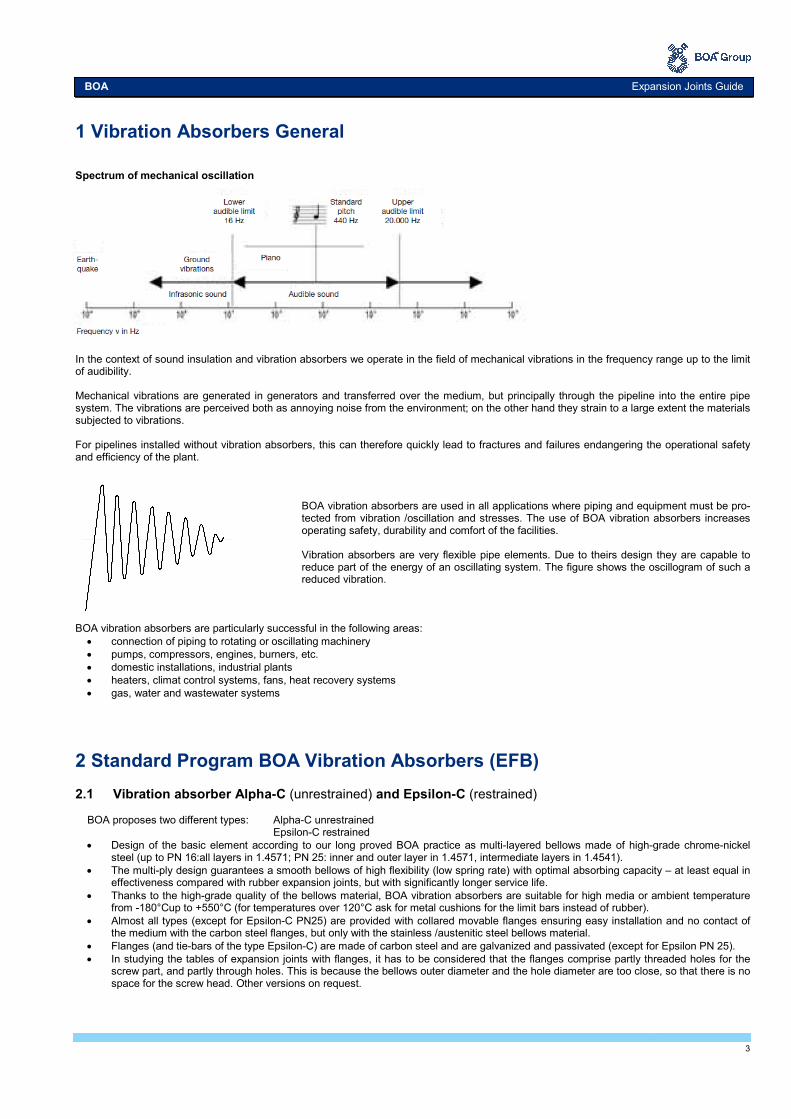
1 Vibration Absorbers General Spectrum of mechanical oscillation In the context of sound insulation and vibration absorbers we operate in the field of mechanical vibrations in the frequency range up to the limit of audibility. Mechanical vibrations are generated in generators and transferred over the medium, but principally through the pipeline into the entire pipe system. The vibrations are perceived both as annoying noise from the environment; on the other hand they strain to a large extent the materials subjected to vibrations. For pipelines installed without vibration absorbers, this can therefore quickly lead to fractures and failures endangering the operational safety and efficiency of the plant.
BOA vibration absorbers are used in all applications where piping and equipment must be pro-tected from vibration /oscillation and stresses. The use of BOA vibration absorbers increases operating safety, durability and comfort of the facilities. Vibration absorbers are very flexible pipe elements. Due to theirs design they are capable to reduce part of the energy of an oscillating system. The figure shows the oscillogram of such a reduced vibration.
BOA vibration absorbers are particularly successful in the following areas:
• connection of piping to rotating or oscillating machinery
• pumps, compressors, engines, burners, etc.
• domestic installations, industrial plants
• heaters, climat control systems, fans, heat recovery systems
• gas, water and wastewater systems
2 Standard Program BOA Vibration Absorbers (EFB) 2.1 Vibration absorber Alpha-C (unrestrained) and Epsilon-C (restrained) BOA proposes two different types: Alpha-C unrestrained Epsilon-C restrained
• Design of the basic element according to our long proved BOA practice as multi-layered bellows made of high-grade chrome-nickel steel (up to PN 16:all layers in 1.4571; PN 25: inner and outer layer in 1.4571, intermediate layers in 1.4541).
• The multi-ply design guarantees a smooth bellows of high flexibility (low spring rate) with optimal absorbing capacity – at least equal in effectiveness compared with rubber expansion joints, but with significantly longer service life.
• Thanks to the high-grade quality of the bellows material, BOA vibration absorbers are suitable for high media or ambient temperature from -180°Cup to +550°C (for temperatures over 120°C ask for metal cushions for the limit bars instead of rubber).
• Almost all types (except for Epsilon-C PN25) are provided with collared movable flanges ensuring easy installation and no contact of the medium with the carbon steel flanges, but only with the stainless /austenitic steel bellows material.
• Flanges (and tie-bars of the type Epsilon-C) are made of carbon steel and are galvanized and passivated (except for Epsilon PN 25).
• In studying the tables of expansion joints with flanges, it has to be considered that the flanges comprise partly threaded holes for the screw part, and partly through holes. This is because the bellows outer diameter and the hole diameter are too close, so that there is no space for the screw head. Other versions on request.
BOA Expansion Joints Guide

4
Type Alpha-C (unrestrained) Type Epsilon-C (restrained)
2.2 Reduction 2.2.1 Expansion capacity NOTE (Hereinafter the term load cycle is used for full load change cycle.) The maximum permissible expansion capacity is indicated on the expansion joint. It refers to 1000 load cycles (for expansion joints conforming to EC standards: 500 load cycles with safety factor 2). At higher load cycles, the expansion capacity must be reduced by the load cycle factor KL according to table 1. For the accurate determination of the load factor KL the following formula can be applied: 2.2.2 Temperature related movement and pressure reduction NOTE The admissible operating pressure is determined by the nominal pressure considering the reduction factor KP according to tab. 2. At higher
temperatures, the expansion capacity K∆ has to be reduced according to the reduction factors.
1) linear interpolation for intermediate values
KL= (1000 / Nadm)0.29
Load cycles Nadm
Load cycle factor KL
1'000 2'000 3'000 5'000
10'000 30'000 50'000
100'000 200'000
1'000'000 25'000'000
1.00 0.82 0.73 0.63 0.51 0.37 0.32 0.26 0.22 0.14 0.05
Table 1
Reduction factors 1) for pressure [KP]
and expansion capacity [K∆]
Temperature °C KP K∆
-10...20 50 100 150
1.00 0.92 0.87 0.83
1.00 0.97 0.94 0.92
200 250
0.79 0.74
0.90 0.88
300 350 400
0.67 0.60 0.53
0.86 0.85 0.84
Table 2

5
3 Installation Instructions Vibration Absorbers 3.1 General safety recommendations Prior to installation and start-up, installation and start-up instructions must be read and observed. Installation, start-up and maintenance work shall only be performed by qualified and authorized staff. Maintenance Vibration absorbers are maintenance free. CAUTION Prior to disassembly and maintenance, the system must be
• depressurized,
• cooled down,
• emptied.
Otherwise there is a risk of accident! Transport, packaging and storage
• The consignment must be checked for completeness upon receipt.
• Any transport damage must be reported to the carrier and the manufacturer.
• At an intermediate storage we recommend to use the original packaging. Admissible ambient conditions for storage and transport:
• ambient temperature - 4°C to +70 °C
• relative humidity up to 95%. Vibration absorbers must be protected against wetness, humidity, dirt, shocks and damage. Warranty A warranty claim requires professional installation and start-up in accordance with installation and start-up instructions. The necessary installa-tion, start-up and maintenance work must be performed by qualified and authorized staff. Operating pressure NOTE
• The permissible operating pressure results in the nominal pressure considering the reduction factors given in section 2.2 "Reduction".
• At higher temperatures, the expansion capacity has to be reduced according to the reduction factors (see section 2.2). Start-up and check Before starting-up check if
• the pipeline is installed with sufficient inclination to avoid water pockets
• there is sufficient drainage
• pipe anchors and pipe supports/ guides are firmly installed prior to filling and pressure testing the system
• the expansion joint is not stressed by torsion, especially not expansion joints with socket attachment
• the flow direction has been observed for expansion joints with inner sleeves
• the steel bellows is free of dirt, welding, plaster or mortar splatters or any other soiling; clean if necessary
• all screwed connections are tightened properly
• the general due diligence requirements to avoid corrosion damage are observed, such as water treatment, or prevention of galvanic corrosion in copper and galvanized pipes.
Insulation Expansion joints may be insulated exactly as the pipeline.
• If no coating is provided, protect the bellows by means of a slidable metal sleeve to avoid insulation material dropping into the convolu-tions.
• If the expansion joint is to be placed under plaster, a protective cover is essential. This ensures the bellows’ function, protects against soiling and avoids contact with structure materials.
. Improper operation
• The limits given in the technical data of the standard range must not be exceeded.
• Swinging suspensions adjacent to expansion joints are not permitted.
• Do not clean the newly installed pipeline by blowing it with steam to avoid water hammers and unacceptable vibration stimulating of the bellows.
System start-up CAUTION
• During pressure testing and operation, the allowable test pressure or operating pressure defined for the expansion joint must not be ex-ceeded.
• Excessive pressure peaks as a consequence of valves closing too abruptly, water hammers etc. are not permitted.
• Avoid contact with aggressive media.
• The start-up of steam lines must be performed such that the condensate has time to drain off.
BOA Expansion Joints Guide

6
3.2 Installation advice Assembly
• Anchor points and pipe guides must be firmly installed before filling and pressure testing the system.
• Expansion joints must be installed without being subject to torsion. This applies particularly to expansion joints with socket connection.
• The steel bellows must be protected against damage and dirt (e.g. welding, plaster or mortar splatter).
• Steam pipelines should be installed in such a way that water hammers are avoided. This can be achieved by adequate drainage, insu-lation, by preventing water pockets and by sufficient inclination of the line.
• Observe the flow direction while installing expansion joints with inner sleeves.
• Avoid the installation of expansion joints in the immediate vicinity of pressure reducers, hot steam coolers and shut-down valves, if high-frequency oscillations are expected due to turbulence. Otherwise special measures must be installed (e.g. thick-walled sleeves, perfo-rated disks, calming sections etc.).
• If high frequency vibrations or turbulence or high flow speed are expected, we recommend the installation of expansion joints with inner sleeve.
• Inner sleeves are also recommended for expansion joints with DN ≥ 150, if the flow speed of air, gas or steam media exceeds 8 m/s, or 3 m/s in case of liquid media.
3.2.1 Unrestrained vibration absorbers, e.g. Alpha-C
Pipe guides, pipe supports
• Provide inclination for drainage
• Align the pipeline, distance between pipe guides according to fig. 1, table 3 and diagram 2 NOTE Sliding or roller supports are the safest measures to avoid buckling and lifting of the pipeline. CAUTION Swing suspensions are not permitted adjacent to expansion joints! Fig. 1
∆ = expansion capacity of the expansion joint [mm]
L1 = max. 2 x DN + ∆/2 [mm] L2 = 0.7 x L3 [mm] L3 = 400 x DN [mm] valid only for steel pipelines L3 is the distance between the pipe supports according to the formula above. If buckling must be expected, L3 must be reduced according to diagram 2. .
Diagram 1
Steam / gas
Nominal size DN
Flo
w s
pee
d
v [m
/s]
Liquid
.

7
DN L1 [mm] L2 [mm] L3 [mm]
15 30 +∆ 1050 1550
20 40 +∆ 1200 1750
25 50 +∆ 1400 2000
32 64 +∆ 1550 2250
40 80 +∆ 1750 2500
50 100 +∆ 1950 2800
65 130 +∆ 2250 3200
80 160 +∆ 2500 3550
100 200 +∆ 2800 4000
125 250 +∆ 3100 4450
150 300 +∆ 3450 4900
200 400 +∆ 3950 5650
250 500 +∆ 4400 6300
300 600 +∆ 4850 6900
350 700 +∆ 5200 7450
400 800 +∆ 5600 8000
450 900 +∆ 5900 8450
500 1000 +∆ 6250 8900
600 1200 +∆ 6850 9800
700 1400 +∆ 7450 10600
800 1600 +∆ 7900 11300
Table 3 (only valid for steel pipelines) Diagram 2 Anchor points
• Install main anchors at locations where the pipeline changes direction.
• Limit by anchors each pipe section to be compensated for. - Only one vibration absorber is allowed between two anchors. - Main anchors must be installed at locations where the pipeline changes direction. They must take up the pressure thrusts of the ex-
pansion joints as well as the frictional forces of the pipe supports/ guides. - Intermediate anchors must be installed if the movement capacity of one axial expansion joint is not sufficient to compensate for the en-
tire expansion of a long pipeline. In that case, several axial expansion joints are required. - In vacuum mode, the anchor points must be capable to take up tensile and pressure forces.
Fig. 2
Fig. 3
Nominal size DN
Anchor point
Guide support
Intermediate anchor between expansion joints
Anchor point Guide support Expansion joint
8
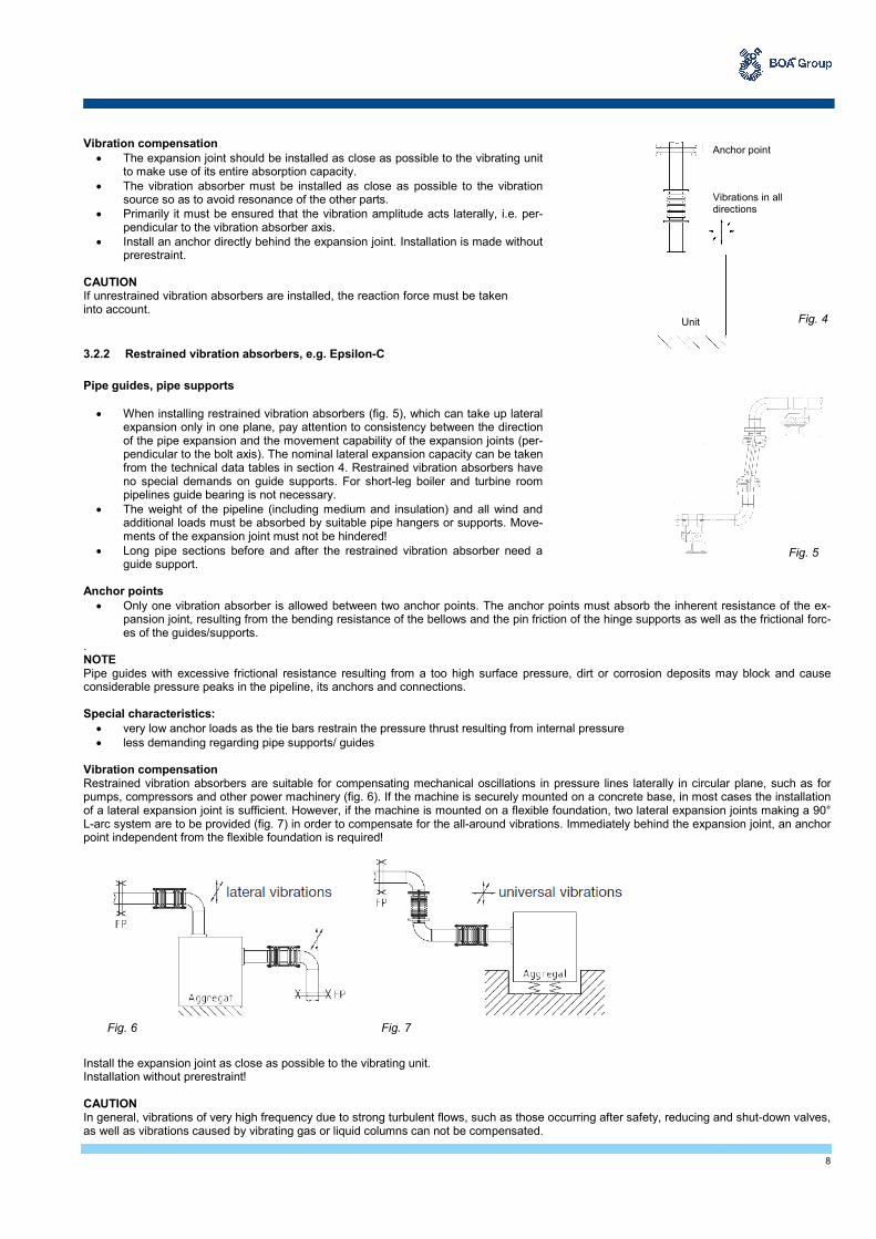
Vibration compensation
• The expansion joint should be installed as close as possible to the vibrating unit to make use of its entire absorption capacity.
• The vibration absorber must be installed as close as possible to the vibration source so as to avoid resonance of the other parts.
• Primarily it must be ensured that the vibration amplitude acts laterally, i.e. per-pendicular to the vibration absorber axis.
• Install an anchor directly behind the expansion joint. Installation is made without prerestraint.
CAUTION If unrestrained vibration absorbers are installed, the reaction force must be taken into account.
3.2.2 Restrained vibration absorbers, e.g. Epsilon-C
Pipe guides, pipe supports
• When installing restrained vibration absorbers (fig. 5), which can take up lateral expansion only in one plane, pay attention to consistency between the direction of the pipe expansion and the movement capability of the expansion joints (per-pendicular to the bolt axis). The nominal lateral expansion capacity can be taken from the technical data tables in section 4. Restrained vibration absorbers have no special demands on guide supports. For short-leg boiler and turbine room pipelines guide bearing is not necessary.
• The weight of the pipeline (including medium and insulation) and all wind and additional loads must be absorbed by suitable pipe hangers or supports. Move-ments of the expansion joint must not be hindered!
• Long pipe sections before and after the restrained vibration absorber need a guide support.
Anchor points
• Only one vibration absorber is allowed between two anchor points. The anchor points must absorb the inherent resistance of the ex-pansion joint, resulting from the bending resistance of the bellows and the pin friction of the hinge supports as well as the frictional forc-es of the guides/supports.
. NOTE Pipe guides with excessive frictional resistance resulting from a too high surface pressure, dirt or corrosion deposits may block and cause considerable pressure peaks in the pipeline, its anchors and connections. Special characteristics:
• very low anchor loads as the tie bars restrain the pressure thrust resulting from internal pressure
• less demanding regarding pipe supports/ guides
Vibration compensation Restrained vibration absorbers are suitable for compensating mechanical oscillations in pressure lines laterally in circular plane, such as for pumps, compressors and other power machinery (fig. 6). If the machine is securely mounted on a concrete base, in most cases the installation of a lateral expansion joint is sufficient. However, if the machine is mounted on a flexible foundation, two lateral expansion joints making a 90° L-arc system are to be provided (fig. 7) in order to compensate for the all-around vibrations. Immediately behind the expansion joint, an anchor point independent from the flexible foundation is required!
Install the expansion joint as close as possible to the vibrating unit. Installation without prerestraint! CAUTION In general, vibrations of very high frequency due to strong turbulent flows, such as those occurring after safety, reducing and shut-down valves, as well as vibrations caused by vibrating gas or liquid columns can not be compensated.
Fig. 4
Anchor point Vibrations in all directions
Unit
Fig. 5
Fig. 6 Fig. 7

9
4 Technical Data BOA Standard Vibration Absorbers (EFB)
4.1 Vibration absorbers Type Alpha-C (unrestrained) Type Alpha-C (unrestrained)
1) Nominal expansion capacity: these indications are meant for 1000 full load cycles SL=1 at 20°C either axial or lateral
Consider the reaction force of the expansion joint: 10x cross section area = reaction force in [N/bar] Type designation: L = with inner sleeve; B = without inner sleeve; * = optionally with/without inner sleeve If an inner guide sleeve is required by the customer, the construction length can be different from the data table below.
DN
PN
Type Nominal expansion
capacity1)
Weig
ht
(w
ithout in
ner
sle
eve) Flange Bellows
Alpha-C
Axia
l
Late
ral
(w
ithout in
ner
s
leeve)
Univ
ers
al
Vib
rations
Overa
ll le
ngth
u
nre
str
ain
ed
Outs
ide Ø
Thic
kness
Hole
circle
Ø
Num
ber
of hole
s
Hole
Ø
Outs
ide Ø
Male
face Ø
Effective a
rea
of
bello
ws
Spring r
ate
±
30%
Spring r
ate
±
30%
±∆ax ±∆lat ± Bl. m D b k n d Ø Da g AB Cax Clat
- - - mm mm mm mm kg mm mm mm - mm mm mm cm2 N/mm N/mm
40 6 Alpha-C 23 12 0.8 130 2.4 130 14 100 4 14 58.5 61.0 27.4 77.0 35.0
40 10 Alpha-C 17 9 0.6 130 4.3 150 16 110 4 18 58.5 58.0 29.8 133.0 86.0
40 16 Alpha-C 17 9 0.6 130 4.3 150 16 110 4 18 58.5 58.0 29.8 133.0 86.0
50 6 Alpha-C 24 11 0.7 130 3.0 140 14 110 4 14 74.4 70.0 40.7 57.0 45.0
50 10 Alpha-C 12 5 0.3 130 5.9 165 18 125 4 18 73.4 70.0 42.0 139.0 133.0
50 16 Alpha-C 12 5 0.3 130 5.9 165 18 125 4 18 73.4 70.0 42.0 139.0 133.0
65 6 Alpha-C 25 8 0.5 130 3.5 160 14 130 4 14 93.7 92.0 68.5 57.0 77.0
65 10 Alpha-C 14 4.5 0.3 130 7.1 185 18 145 4 18 93.0 92.0 70.3 130.0 244.0
65 16 Alpha-C 14 4.5 0.3 130 7.1 185 18 145 4 18 93.0 92.0 70.3 130.0 244.0
80 6 Alpha-C 26 7 0.4 130 5.8 190 16 150 4 18 104.9 106.0 86.6 51.0 138.0
80 10 Alpha-C 22 6 0.4 130 8.5 200 20 160 8 18 104.2 106.0 88.6 120.0 296.0
80 16 Alpha-C 22 6 0.4 130 8.5 200 20 160 8 18 104.2 106.0 88.6 120.0 296.0
100 6 Alpha-C 30 7 0.4 130 7.0 210 16 170 4 18 136.0 134.0 129.4 48.0 145.0
100 10 Alpha-C 22 5 0.3 130 11.0 220 20 180 8 18 135.6 134.0 131.9 114.0 476.0
100 16 Alpha-C 22 5 0.3 130 11.0 220 20 180 8 18 135.6 134.0 131.9 114.0 476.0
125 6 Alpha-C 28 5 0.3 130 9.2 240 18 200 8 18 157.7 162.0 188.6 58.0 290.0
125 10 Alpha-C 24 4 0.2 130 15.2 250 22 210 8 18 157.0 162.0 191.6 155.0 910.0
125 16 Alpha-C 24 4 0.2 130 15.2 250 22 210 8 18 157.0 162.0 191.6 155.0 910.0
150 6 Alpha-C 27 4 0.2 130 12.0 265 20 225 8 18 195.0 190.0 266.0 98.0 770.0
150 10 Alpha-C 20 3 0.2 130 18.5 285 22 240 8 22 185.2 190.0 269.3 148.0 1175.0
150 16 Alpha-C 20 3 0.2 130 18.5 285 22 240 8 22 185.2 190.0 269.3 148.0 1175.0
175 6 Alpha-C 24 3 0.2 130 13.5 295 22 255 8 M16 228.0 230.0 347.0 100.0 983.0
175 10 Alpha-C 17 2 0.1 130 23.8 315 26 270 8 22 229.0 230.0 354.3 218.0 2620.0
175 16 Alpha-C 17 2 0.1 130 23.8 315 26 270 8 22 229.0 230.0 354.3 218.0 2620.0
BOA Expansion Joints Guide

10
DN
PN
Type Nominal expansion
capacity1)
Weig
ht
(w
ithout in
ner
sle
eve) Flange Bellows
Alpha-C
Axia
l
Late
ral
(w
ithout in
ner
s
leeve)
Univ
ers
al
Vib
rations
Overa
ll le
ngth
u
nre
str
ain
ed
Outs
ide Ø
Thic
kness
Hole
circle
Ø
Num
ber
of hole
s
Hole
Ø
Outs
ide Ø
Male
face Ø
Effective a
rea
of
bello
ws
Spring r
ate
±
30%
Spring r
ate
±
30%
±∆ax ±∆lat ± Bl. m D b k n d Ø Da g AB Cax Clat
- - - mm mm mm mm kg mm mm mm - mm mm mm cm2 N/mm N/mm
200 6 Alpha-C 24 2.5 0.1 130 17.3 320 22 280 8 18 250.0 256.0 437.4 98.0 1228.0
200 10 Alpha-C 25 3 0.2 130 24.9 340 26 295 8 22 254.0 256.0 441.8 162.0 2420.0
200 16 Alpha-C 18 2 0.1 130 25.5 340 26 295 12 22 253.0 256.0 445.6 314.0 5585.0
250 6 Alpha-C 22 2 0.1 130 22.8 375 24 335 12 18 304.0 308.0 662.3 121.0 2795.0
250 10 Alpha-C 23 2 0.1 130 34.8 395 28 350 12 22 308.0 308.0 672.4 170.0 4800.0
250 16 Alpha-C 16 1 0.1 130 40.0 405 32 355 12 26 306.5 308.0 672.4 498.0 14593.0
300 6 Alpha-C 28 2 0.1 130 31.5 440 24 395 12 22 356.0 361.0 928.3 132.0 4344.0
300 10 Alpha-C 20 1 0.1 130 39.2 445 28 400 12 22 359.0 360.0 928.3 200.0 6380.0
300 16 Alpha-C 15 1 0.1 130 47.7 460 32 410 12 26 361.0 361.0 928.3 570.0 29525.0
350 6 Alpha-C 39 3 0.2 200 44.5 490 26 445 12 22 397.0 400.0 1086.9 153.0 1721.0
350 10 Alpha-C 33 3 0.2 200 57.4 505 30 460 16 22 397.0 400.0 1086.9 240.0 3046.0
350 16 Alpha-C 28 2 0.1 200 77.5 520 36 470 16 26 399.0 400.0 1086.9 437.0 7537.0
400 6 Alpha-C 40 3 0.2 200 53.4 540 28 495 16 22 449.0 453.0 1405.3 152.0 2199.0
400 10 Alpha-C 34 2 0.1 200 72.8 565 32 515 16 26 450.0 453.0 1405.3 239.0 3889.0
400 16 Alpha-C 30 2 0.1 200 99.1 580 38 525 16 30 452.0 453.0 1405.3 510.0 11293.0
450 6 Alpha-C 42 3 0.2 200 61.6 595 28 550 16 22 504.0 508.0 1787.0 151.0 2761.0
450 10 Alpha-C 38 3 0.2 200 83.8 615 32 565 20 26 505.0 508.0 1787.0 298.0 6144.0
450 16 Alpha-C 33 2 0.1 200 125.0 640 42 585 20 30 506.0 508.0 1787.0 506.0 14121.0
500 6 Alpha-C 38 3 0.2 200 71.2 645 30 600 20 22 555.0 558.0 2189.6 173.0 3845.0
500 10 Alpha-C 39 3 0.2 200 98.5 670 34 620 20 26 556.0 558.0 2185.4 309.0 7765.0
500 16 Alpha-C 25 1.5 0.1 200 159.2 715 44 650 20 33 557.0 558.0 2181.3 771.0 26124.0
1) Nominal expansion capacity: these indications are meant for 1000 full load cycles SL=1 at 20°C either axial or lateral
Consider the reaction force of the expansion joint: 10x cross section area = reaction force in [N/bar] Type designation: L = with inner sleeve; B = without inner sleeve; * = optionally with/without inner sleeve If an inner guide sleeve is required by the customer, the construction length can be different from the data table. Type Alpha-C (unrestrained)
Subject to changes; latest specifications on www.boagroup.com

11
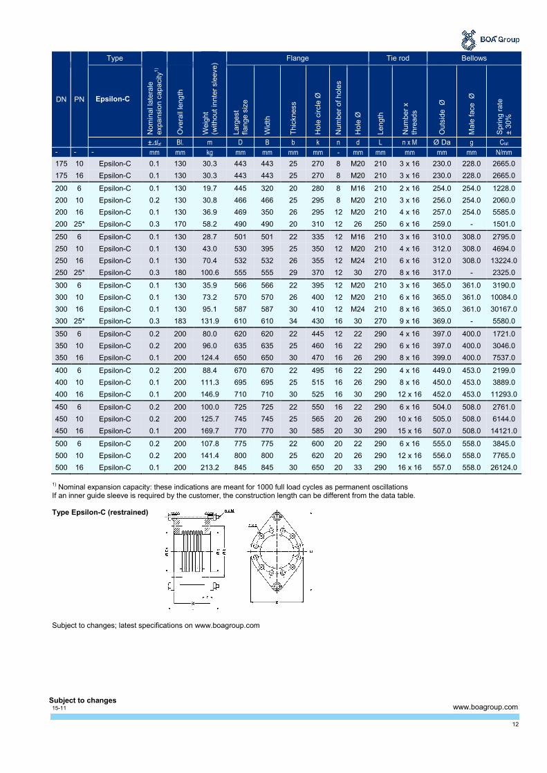
4.2 Vibration absorbers Type Epsilon-C (restrained) Type Epsilon-C (restrained)
1) Nominal expansion capacity: these indications are meant for 1000 full load cycles as permanent oscillations
If an inner guide sleeve is required by the customer, the construction length can be different from the data table below.
DN PN
Type
Nom
inal la
tera
le
expansio
n c
apacity
1)
Weig
ht
(w
ithout in
nte
r sle
eve)
Flange Tie rod Bellows
Epsilon-C
Overa
ll le
ngth
Larg
est
fla
nge s
ize
Wid
th
Thic
kness
Hole
circle
Ø
Num
ber
of hole
s
Hole
Ø
Length
Num
ber
x
thre
ads
Outs
ide Ø
Male
face Ø
Spring r
ate
±
30%
±∆lat Bl. m D B b k n d L n x M Ø Da g Clat
- - - mm mm kg mm mm mm mm - mm mm mm mm mm N/mm
40 6 Epsilon-C 0.8 130 3.5 211 130 12.5 100 4 14 188 2 x 12 58.5 61.0 35.0
40 10 Epsilon-C 0.6 130 5.8 231 150 16.5 110 4 18 188 2 x 12 58.5 58.0 86.0
40 16 Epsilon-C 0.6 130 5.8 231 150 16.5 110 4 18 188 2 x 12 58.5 58.0 86.0
40 25* Epsilon-C 0.2 130 6.1 245 150 15 110 4 18 188 2 x 12 68.0 - 113.0
50 6 Epsilon-C 0.7 130 3.7 221 140 12.5 110 4 14 188 2 x 12 74.4 70.0 45.0
50 10 Epsilon-C 0.3 130 7.3 246 165 18.5 125 4 18 188 2 x 12 73.4 70.0 133.0
50 16 Epsilon-C 0.3 130 7.3 246 165 18.5 125 4 18 188 2 x 12 73.4 70.0 133.0
50 25* Epsilon-C 0.1 122 6.8 260 165 15 125 4 18 188 2 x 12 81.0 - 194.0
65 6 Epsilon-C 0.5 130 4.5 241 160 12.5 130 4 14 188 2 x 12 93.7 92.0 94.0
65 10 Epsilon-C 0.3 130 8.4 266 185 18.5 145 4 18 188 2 x 12 93.0 92.0 244.0
65 16 Epsilon-C 0.3 130 8.4 266 185 18.5 145 4 18 188 2 x 12 93.0 92.0 244.0
80 6 Epsilon-C 0.4 130 6.5 271 190 14.5 150 4 18 188 2 x 12 104.9 106.0 121.0
80 10 Epsilon-C 0.4 130 10.1 281 200 20.5 160 8 18 188 2 x 12 104.2 106.0 296.0
80 16 Epsilon-C 0.4 130 10.1 281 200 20.5 160 8 18 188 2 x 12 104.2 106.0 296.0
80 25* Epsilon-C 0.3 160 12.5 285 200 20 160 8 18 228 2 x 12 108.0 - 240.0
100 6 Epsilon-C 0.4 130 7.6 291 210 14.5 170 4 M16 188 2 x 12 136.0 134.0 190.0
100 10 Epsilon-C 0.3 130 13.7 347 220 20.5 180 8 18 210 2 x 16 135.6 134.0 476.0
100 16 Epsilon-C 0.3 130 13.7 347 220 20.5 180 8 18 210 2 x 16 135.6 134.0 476.0
100 25* Epsilon-C 0.3 160 18.3 375 235 20 190 8 22 250 2 x 16 146.0 - 392.0
125 6 Epsilon-C 0.3 130 9.7 323 240 16 200 8 18 188 2 x 12 157.7 162.0 249.0
125 10 Epsilon-C 0.2 130 18.2 377 250 22.5 210 8 18 210 2 x 16 157.0 162.0 881.0
125 16 Epsilon-C 0.2 130 18.2 377 250 22.5 210 8 18 210 2 x 16 157.0 162.0 881.0
125 25* Epsilon-C 0.3 170 40.6 400 400 20 220 8 26 250 3 x 16 174.0 - 463.0
150 6 Epsilon-C 0.2 130 14.4 390 265 18.5 225 8 18 210 2 x 16 185.9 190.0 734.0
150 10 Epsilon-C 0.2 130 23.3 413 413 22.5 240 8 M20 210 3 x 16 185.2 190.0 1285.0
150 16 Epsilon-C 0.2 130 23.3 413 413 22.5 240 8 M20 210 3 x 16 185.2 190.0 1285.0
150 25* Epsilon-C 0.3 160 45.7 430 430 20 250 8 26 250 3 x 16 204.0 - 795.0
175 6 Epsilon-C 0.2 130 18.0 420 295 20 255 8 M16 210 2 x 16 228.0 228.0 983.0
12
DN PN
Type
Nom
inal la
tera
le
expansio
n c
apacity
1)
Weig
ht
(w
ithout in
nte
r sle
eve)
Flange Tie rod Bellows
Epsilon-C
Overa
ll le
ngth
Larg
est
fla
nge s
ize
Wid
th
Thic
kness
Hole
circle
Ø
Num
ber
of hole
s
Hole
Ø
Length
Num
ber
x
thre
ads
Outs
ide Ø
Male
face Ø
Spring r
ate
±
30%
±∆lat Bl. m D B b k n d L n x M Ø Da g Clat
- - - mm mm kg mm mm mm mm - mm mm mm mm mm N/mm
175 10 Epsilon-C 0.1 130 30.3 443 443 25 270 8 M20 210 3 x 16 230.0 228.0 2665.0
175 16 Epsilon-C 0.1 130 30.3 443 443 25 270 8 M20 210 3 x 16 230.0 228.0 2665.0
200 6 Epsilon-C 0.1 130 19.7 445 320 20 280 8 M16 210 2 x 16 254.0 254.0 1228.0
200 10 Epsilon-C 0.2 130 30.8 466 466 25 295 8 M20 210 3 x 16 256.0 254.0 2060.0
200 16 Epsilon-C 0.1 130 36.9 469 350 26 295 12 M20 210 4 x 16 257.0 254.0 5585.0
200 25* Epsilon-C 0.3 170 58.2 490 490 20 310 12 26 250 6 x 16 259.0 - 1501.0
250 6 Epsilon-C 0.1 130 28.7 501 501 22 335 12 M16 210 3 x 16 310.0 308.0 2795.0
250 10 Epsilon-C 0.1 130 43.0 530 395 25 350 12 M20 210 4 x 16 312.0 308.0 4694.0
250 16 Epsilon-C 0.1 130 70.4 532 532 26 355 12 M24 210 6 x 16 312.0 308.0 13224.0
250 25* Epsilon-C 0.3 180 100.6 555 555 29 370 12 30 270 8 x 16 317.0 - 2325.0
300 6 Epsilon-C 0.1 130 35.9 566 566 22 395 12 M20 210 3 x 16 365.0 361.0 3190.0
300 10 Epsilon-C 0.1 130 73.2 570 570 26 400 12 M20 210 6 x 16 365.0 361.0 10084.0
300 16 Epsilon-C 0.1 130 95.1 587 587 30 410 12 M24 210 8 x 16 365.0 361.0 30167.0
300 25* Epsilon-C 0.3 183 131.9 610 610 34 430 16 30 270 9 x 16 369.0 - 5580.0
350 6 Epsilon-C 0.2 200 80.0 620 620 22 445 12 22 290 4 x 16 397.0 400.0 1721.0
350 10 Epsilon-C 0.2 200 96.0 635 635 25 460 16 22 290 6 x 16 397.0 400.0 3046.0
350 16 Epsilon-C 0.1 200 124.4 650 650 30 470 16 26 290 8 x 16 399.0 400.0 7537.0
400 6 Epsilon-C 0.2 200 88.4 670 670 22 495 16 22 290 4 x 16 449.0 453.0 2199.0
400 10 Epsilon-C 0.1 200 111.3 695 695 25 515 16 26 290 8 x 16 450.0 453.0 3889.0
400 16 Epsilon-C 0.1 200 146.9 710 710 30 525 16 30 290 12 x 16 452.0 453.0 11293.0
450 6 Epsilon-C 0.2 200 100.0 725 725 22 550 16 22 290 6 x 16 504.0 508.0 2761.0
450 10 Epsilon-C 0.2 200 125.7 745 745 25 565 20 26 290 10 x 16 505.0 508.0 6144.0
450 16 Epsilon-C 0.1 200 169.7 770 770 30 585 20 30 290 15 x 16 507.0 508.0 14121.0
500 6 Epsilon-C 0.2 200 107.8 775 775 22 600 20 22 290 6 x 16 555.0 558.0 3845.0
500 10 Epsilon-C 0.2 200 141.4 800 800 25 620 20 26 290 12 x 16 556.0 558.0 7765.0
500 16 Epsilon-C 0.1 200 213.2 845 845 30 650 20 33 290 16 x 16 557.0 558.0 26124.0
1) Nominal expansion capacity: these indications are meant for 1000 full load cycles as permanent oscillations
If an inner guide sleeve is required by the customer, the construction length can be different from the data table. Type Epsilon-C (restrained)
Subject to changes; latest specifications on www.boagroup.com
www.boagroup.com Subject to changes 15-11