-u · practice and procedure ("rpp"). -2- proposed electrical facilities 5. ea1 proposes...
TRANSCRIPT
BEFORE THE ARKANSAS PUBLIC SERVICE COMMISSION:-:: t i ':: T)
f / 1 *- w w cru
IN THE MAlTER OF THE APPLICATION 1 OF ENTERGY ARKANSAS, INC. FOR A ) CERTIFICATE OF ENVIRONMENTAL 1 COMPATIBILITY AND PUBLIC NEED TO ) CONSTRUCT AND OPERATE THE SANS ) SOUCl500 KV SWITCHING STATION AND ) RELATED 500 KV TRANSMISSION LINE 1 AND ASSOCIATED TRANSMISSION ) FACILITIES, IN MISSISSIPPI COUNTY, ) ARKANSAS )
DOCKET NO. 02-6gb -U
APPLICATION FOR A CERTIFICATE OF ENVIRONMENTAL COMPATIBILITY AND PUBLIC NEED
COMES NOW Entergy Arkansas, Inc. (%AI'' or the "Company"), and for its
Application for a Certificate of Environmental Compatibility and Public Need,
states:
DESCRIPTION OF THE COMPANY
1. EA1 is a corporation organized under the laws of the State of
Arkansas, and is a public utility, as defined by Act 324 of 1935, as amended and
codified at Ark. Code Ann. § 23-1-101 et seq. The Company's property consists
of facilities for the generation, transmission, and distribution of electric power and
energy to retail and wholesale customers. These facilities are located principally
in the State of Arkansas. As of December 31, 2001, the Company provided retail
electrical service subject to the jurisdiction of the Arkansas Public Service
Commission ("APSC" or the "Commission") to a total of 648,226 customers. Of

these customers, 547,980 were residential; 77,503 were commercial; 22,241
were industrial; and 502 were public agencies or institutions.
2. EA1 owns or operates five large oil and gas-fueled steam electric
generation stations, four coal-fueled generating units, four combustion turbine
generating units, one diesel electric unit, two hydroelectric plants, and two
nuclear generating units, for a total owned generating capacity of approximately
5,041 MW.
3. EA1 also owns and operates approximately 935 circuit miles of
extra high voltage transmission line of 345 kV or greater; 260 circuit miles of
transmission line of 230 kV; 3,450 circuit miles of transmission lines of 161 kV
and lower; transmission substations; distribution substations; and associated
facilities necessary to provide electric service.
JURISDICTION AND APPLICABLE LAW
4. EA1 is a public utility subject to the jurisdiction of the Commission.
The proposed facilities that are the subject of this Application constitute a ''major
utility facility" within the meaning of the Utility Facility Environmental and
Economic Protection Act, codified at Ark. Code Ann. Q 23-18-501 et seq. (the
"Major Facilities Act"). This Application is, therefore, being filed pursuant to the
Major Facilities Act and Rules 2, 4, and 7.09 of the Commission's Rules of
Practice and Procedure ("RPP").
-2-

PROPOSED ELECTRICAL FACILITIES
5. EA1 proposes to construct and operate a new, 500 kV switching
station, two 500 kV line segments of approximately 1.5 miles in length each
(7,800 feet), and related facilities in Mississippi County, Arkansas (the "Proposed
Electrical Facilities"). The Proposed Electrical Facilities are more fully described
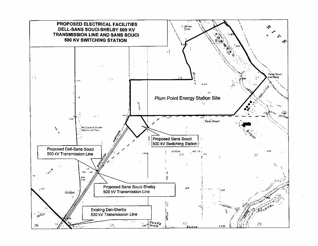
in EA1 Application Exhibits A, B, C, and - D. EA1 Application Exhibit A shows the
route of the transmission line and indicates the location of the Proposed
Electrical Facilities. EA1 Application Exhibit B shows the Proposed Electrical
Facilities along with EAl's local area electrical system. EA1 Application Exhibit C
shows the Proposed Electrical Facilities along with the Company's regional area
electrical system. EA1 Application Exhibit D is a detailed description of the
Proposed Electrical Facilities.
6. The Proposed Electrical Facilities will include a new 500 kV
switching station ("Sans Souci 500 kV Switching Station") to be built on a site
near Osceola, Arkansas at Sans Souci, which site has been secured with a
purchase option by Plum Point Energy Associates, LLC ("PPEA"), an affiliate of
LS Power Development, LLC. Two new connecting segments of 500 kV
transmission line will be built from the new Sans Souci 500 kV Switching Station
to the existing Dell 500 kV Substation to the Shelby 500 kV Substation
Transmission Line (the "Dell-Shelby 500 kV Transmission Line").
7. The Company projects a life expectancy of 40 years for the
Proposed Electrical Facilities based upon periodical depreciation studies that
estimate the remaining life of transmission lines and other facilities depending on
the maintenance and improvements performed on them. If the transmission line
- 3 -
is abandoned, EA1 will remove the conductors and structures from the right of
way. Any salvaged material will be sold as scrap and the right-of-way will revert
to the owners. The estimated cost in current dollars to remove the transmission
line and transmission facilities is approximately $1.5 million, with salvage values
less than $500,000. Reuse of transmission type material is very unlikely due to
possible contamination or possible damage to the material during removal.
PROPOSED AND ALTERNATE ROUTES
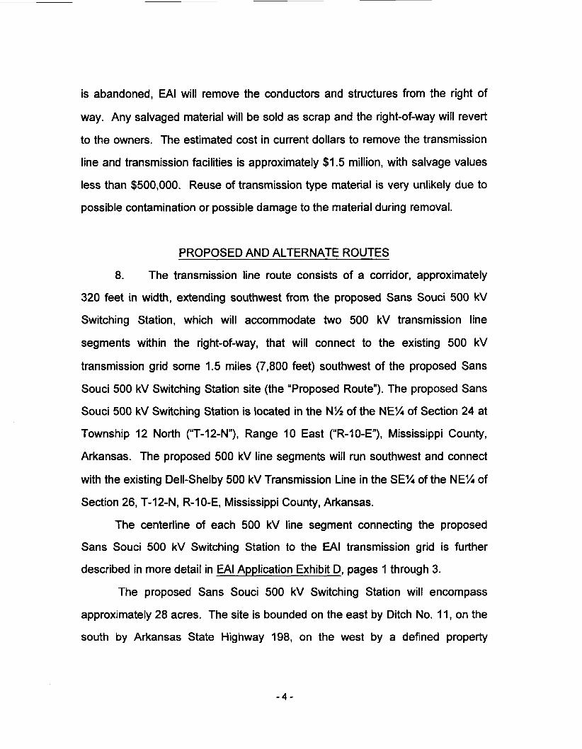
8. The transmission line route consists of a corridor, approximately
320 feet in width, extending southwest from the proposed Sans Souci 500 kV
Switching Station, which will accommodate two 500 kV transmission line
segments within the right-of-way, that will connect to the existing 500 kV
transmission grid some 1.5 miles (7,800 feet) southwest of the proposed Sans
Souci 500 kV Switching Station site (the “Proposed Route”). The proposed Sans
Souci 500 kV Switching Station is located in the N% of the NE% of Section 24 at
Township 12 North (“T-l2-N”), Range 10 East (“R-1 0-E”), Mississippi County,
Arkansas. The proposed 500 kV line segments will run southwest and connect
with the existing Dell-Shelby 500 kV Transmission Line in the SEX of the NE% of
Section 26, T-12-N, R-1 0-E, Mississippi County, Arkansas.
The centerline of each 500 kV line segment connecting the proposed
Sans Souci 500 kV Switching Station to the EA1 transmission grid is further
described in more detail in EA1 Application Exhibit D, pages 1 through 3.
The proposed Sans Souci 500 kV Switching Station will encompass
approximately 28 acres. The site is bounded on the east by Ditch No. 11, on the
south by Arkansas State Highway 198, on the west by a defined property
- 4 -

boundary and the Burlington Northern Santa Fe (“BNSF”) mainline railroad track,
and on the north by the BNSF spur track.
9. An alternate transmission line route to the east, measuring
approximately 3.1 miles (16,500 feet), connects to the Dell-Shelby 500 kV
Transmission Line. This route requires the relocation of the proposed 500 kV
Switching Station site to the east of the preferred site and northeast of Arkansas
State Highways 239 and 198. The alternate route parallels drainage ditches for
the most of the way and begins at the alternate Sans Souci 500 kV Switching
Station site located in the SE% of the SEX of Section 18 at T-12-NI R-1 1-E,
Mississippi County, Arkansas. This alternate route is described in more detail in
EA1 Application Exhibit D, pages 3 and 4.
10. The Proposed Route is the shorter route for the Proposed Electrical
Facilities, is the route preferred by the single landowner who would be affected,
crosses the least amount of agricultural land, and parallels the existing linear
features. In addition, all real estate rights for the Proposed Route have been
secured by PPEA from the single landowner.
NEED FOR PROPOSED ELECTRICAL FACILITIES
11. PPEA is developing a new merchant power coal-fired g n rating
station (“Plum Point Energy Station”) in Mississippi County and has requested
interconnecting service with the Company’s transmission grid. The maximum
generating capacity of the Plum Point Energy Station is being designed to
accommodate up to 1,600 MW of output and may include up to two steam
turbine generator sets. The Proposed Electrical Facilities are required to allow
- 5 -

PPEA to export power from the facility to the electrical grid for sale to wholesale
customers. PPEA intends to apply for exempt wholesale generator status, and
EA1 is required by federal law to provide access to the Company's transmission
facilities, upon reasonable terms and conditions, for an exempt wholesale
generator.
COST AND METHOD OF FINANCING
12. The total project cost of the Proposed Electrical Facilities is
estimated to be: $(million)
500 kV Transmission Segments
500 kV Switching Station
Metering
Relay and Communications
Corporate Loading
$3.9 8.0 0.2 1.4
7.0
Total $20.5
PPEA will reimburse EA1 for the costs of interconnecting its power plant with
EAl's transmission facilities, as provided for in the applicable Federal Energy
Regulatory Commission regulations and in Rule 3.6(a) of the APSC's
Cogeneration Rules, and as specifically agreed to in the Interconnection
Agreement negotiated by PPEA and the Company, which is filed herewith as - EA1
Exhibit JPZ-1 to the Direct Testimony of Mr. John P. Zimmerman. PPEA will pay
EA1 for the cost of the Interconnection Facilities through Contributions in Aid of
Construction so that these facilities will have no effect on EAl's retail rate base or
- 6 -
rates. See, Direct Testimony of Company witness Mr. Gregory R. Zakrzewski,
filed in this Docket.
ECONOMIC IMPACT UPON THE COMMUNITY. ~-
THE COMPANY~ AND ITS CUSTOMERS '
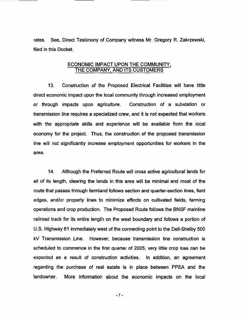
13. Construction of the Proposed Electrical Facilities will have little
direct economic impact upon the local community through increased employment
or through impacts upon agriculture. Construction of a substation or
transmission line requires a specialized crew, and it is not expected that workers
with the appropriate skills and experience will be available from the local
economy for the project. Thus, the construction of the proposed transmission
line will not significantly increase employment opportunities for workers in the
area.
14. Although the Preferred Route will cross active agricultural lands for
all of its length, clearing the lands in this area will be minimal and most of the
route that passes through farmland follows section and quarter-section lines, field
edges, and/or property lines to minimize effects on cultivated fields, farming
operations and crop production. The Proposed Route follows the BNSF mainline
railroad track for its entire length on the west boundary and follows a portion of
U.S. Highway 61 immediately west of the connecting point to the Dell-Shelby 500
kV Transmission Line. However, because transmission line construction is
scheduled to commence in the first quarter of 2005, very little crop loss can be
expected as a result of construction activities. In addition, an agreement
regarding the purchase of real estate is in place between PPEA and the
landowner. More information about the economic impacts on the local
-7-
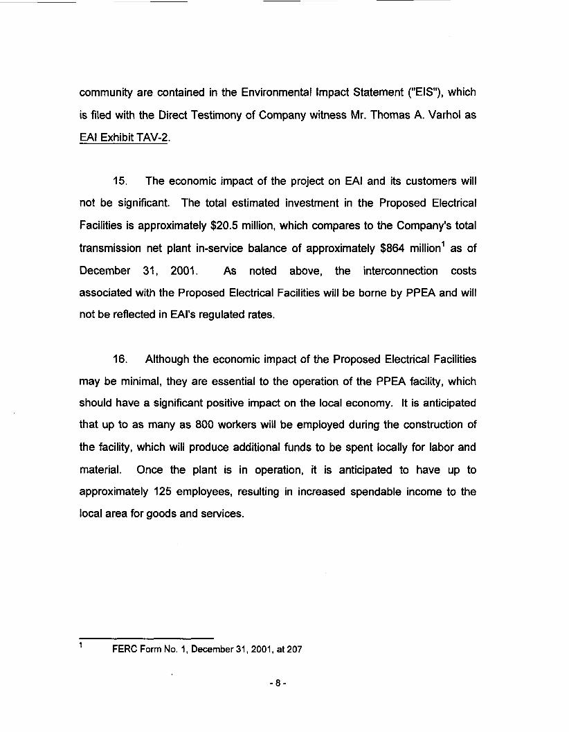
community are contained in the Environmental Impact Statement ("EIS"), which
is filed with the Direct Testimony of Company witness Mr. Thomas A. Varhol as
EA1 Exhibit TAV-2.
15. The economic impact of the project on EA1 and its customers will
not be significant. The total estimated investment in the Proposed Electrical
Facilities is approximately $20.5 million, which compares to the Company's total
transmission net plant in-service balance of approximately $864 million' as of
December 31, 2001. As noted above, the interconnection costs
associated with the Proposed Electrical Facilities will be borne by PPEA and will
not be reflected in EAl's regulated rates.
16. Although the economic impact of the Proposed Electrical Facilities
may be minimal, they are essential to the operation of the PPEA facility, which
should have a significant positive impact on the local economy. It is anticipated
that up to as many as 800 workers will be employed during the construction of
the facility, which will produce additional funds to be spent locally for labor and
material. Once the plant is in operation, it is anticipated to have up to
approximately 125 employees, resulting in increased spendable income to the
local area for goods and services.
FERC Form No. 1, December 31,2001, at 207 1
- 8 -

ENVIRONMENTAL IMPACT
17. Once operational, the proposed Sans Souci 500 kV Switching
Station and transmission line segments will have little, if any, adverse impacts on
the surrounding environment. The Company retained the services of Black and
Veatch Corporation of Overland Park, Kansas, to review the project
requirements, and to recommend a preferred route from the pre-selected line
routes, and to prepare an EIS for the Proposed Electrical Facilities and alternate
transmission line routes. Additionally, PPEA retained Burns & McDonnell,
Engineers-Architects-Consultants of Kansas City, Missouri, to perform a Phase I
Cultural Resources Investigation. The results of the investigation are discussed
in the EIS and the Direct Testimony of Mr. Eric W. Crawford, the PPEA Project
Manager. The Proposed Route parallels a mainline railroad track and in general
follows property boundary lines and field edges and, therefore, avoids
residences, thereby minimizing the impacts on environmentally sensitive areas.
The Proposed Route also minimizes the visual impact of the line and its impact
on wetlands and forested areas by using modular structure designs.
PROOF OF SERVICE AND NOTICE
18. EA1 has caused a copy of this Application and a copy of a map
depicting the location of the Proposed Electrical Facilities to be served upon the
appropriate individuals, public officials, and governmental agencies, as required
by Ark. Code Ann. § 23-18-513. Proof of service upon these individuals is
included in EA1 Application Exhibit E.
19. In addition, EA1 will cause a notice of the filing of this Application, in
compliance with Ark. Code Ann. § 23-18-513 and with RPP 7.09, to be published
- 9 -

on two separate occasions in the Osceola Times, a newspaper having
substantial circulation in the area under consideration. Certification of Proof of
Public Notice will be filed in this Docket at a later time.
WITNESSES
20. The Direct Testimonies and Exhibits of Messrs. Rajesh Gupta, Eric
W. Crawford, Thomas A. Varhol, Murry K. Witcher, John P. Zimmerman 111, and
Gregory R. Zakrzewski are filed in support of this Application.
SERVICE LIST
21. EA1 requests that the following individuals be placed on the service
list as its representatives in this Docket:
Steven K. Strickland, Vice President, Regulatory Affairs Entergy Arkansas, Inc. P. 0. Box 551 Little Rock, Arkansas 72203 Telephone: (501) 3774457
Jeff Broadwater, Assistant General Counsel Entergy Services, Inc. P. 0. Box 551 Little Rock, Arkansas 72203 Telephone: (501) 377-4372
WHEREFORE, EA1 respectfully requests that the Commission grant the
Company a Certificate of Environmental Compatibility and Public Need
authorizing construction and operation of the Proposed Electrical Facilities, and
for all other appropriate relief.
- 1 0 -

Respectively submitted,
ENTERGY ARKANSAS, INC.
Vice President, Regulatory Affairs Entergy Arkansas, Inc. P. 0. Box 551 Little Rock, AR 72203 Telephone: (501) 377-4457
DATED this 22% day of March 2002.
- 11 -

BEFORE THE ARKANSAS PUBLIC SERVICE COMMISSION
IN THE MATTER OF THE APPLICATION ) OF ENTERGY ARKANSAS, INC. FOR A 1 CERTIFICATE OF ENVIRONMENTAL 1 COMPATIBILITY AND PUBLIC NEED TO 1 CONSTRUCT AND OPERATE THE SANS ) SOUCl500 KV SWITCHING STATION AND ) RELATED 500 KV TRANSMISSION LINE ) AND ASSOCIATED TRANSMISSION ) FACILITIES, IN MISSISSIPPI COUNTY, ) ARKANSAS 1
DOCKET NO. 02- -U
EA1 APPLICATION EXHIBIT A
LOCATION MAP - PROPOSED ELECTRICAL FACILITIES
235
2 0 * F

BEFORE THE ARKANSAS PUBLIC SERVICE COMMISSION
IN THE MATTER OF THE APPLICATION OF ENTERGY ARKANSAS, INC. FOR A CERTIFICATE OF ENVIRONMENTAL COMPATIBILITY AND PUBLIC NEED TO 1 CONSTRUCT AND OPERATE THE SANS 1 DOCKET NO. 02- SOUCl500 KV SWITCHING STATION AND ) RELATED 500 KV TRANSMISSION LINE ) AND ASSOCIATED TRANSMISSION FACILITIES, IN MISSISSIPPI COUNTY, ) ARKANSAS )
-U
EA1 APPLICATION EXHIBIT B
LOCATION MAP - LOCAL AREA ELECTRICAL FACILITIES
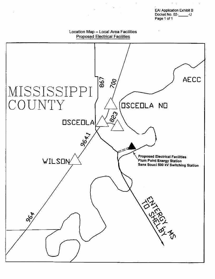
EA1 Application Exhibit B Docket No. 02- -U Page 1 of 1
Location Map - Local Area Facilities Proposed Electrical Facilities
ISSISSIPPI COUNTY
osc
I P ) AECC I - '\I
W I L S O d
NO
Proposed Electrical Facilities Plum Point Energy Station Sans Souci 500 kV Switching Station Y '

BEFORE THE ARKANSAS PUBLIC SERVICE COMMISSION
IN THE MATTER OF THE APPLICATION ) OF ENTERGY ARKANSAS, INC. FOR A ) CERTIFICATE OF ENVIRONMENTAL 1 COMPATIBILITY AND PUBLIC NEED TO ) CONSTRUCT AND OPERATE THE SANS 1 -U SOUCl500 KV SWITCHING STATION AND RELATED 500 KV TRANSMISSION LINE ) AND ASSOCIATED TRANSMISSION ) FACILITIES, IN MISSISSIPPI COUNTY, 1 ARKANSAS )
DOCKET NO. 02- )
EA1 APPLICATION EXHIBIT C
LOCATION MAP - REGIONAL AREA ELECTRICAL FACILITIES
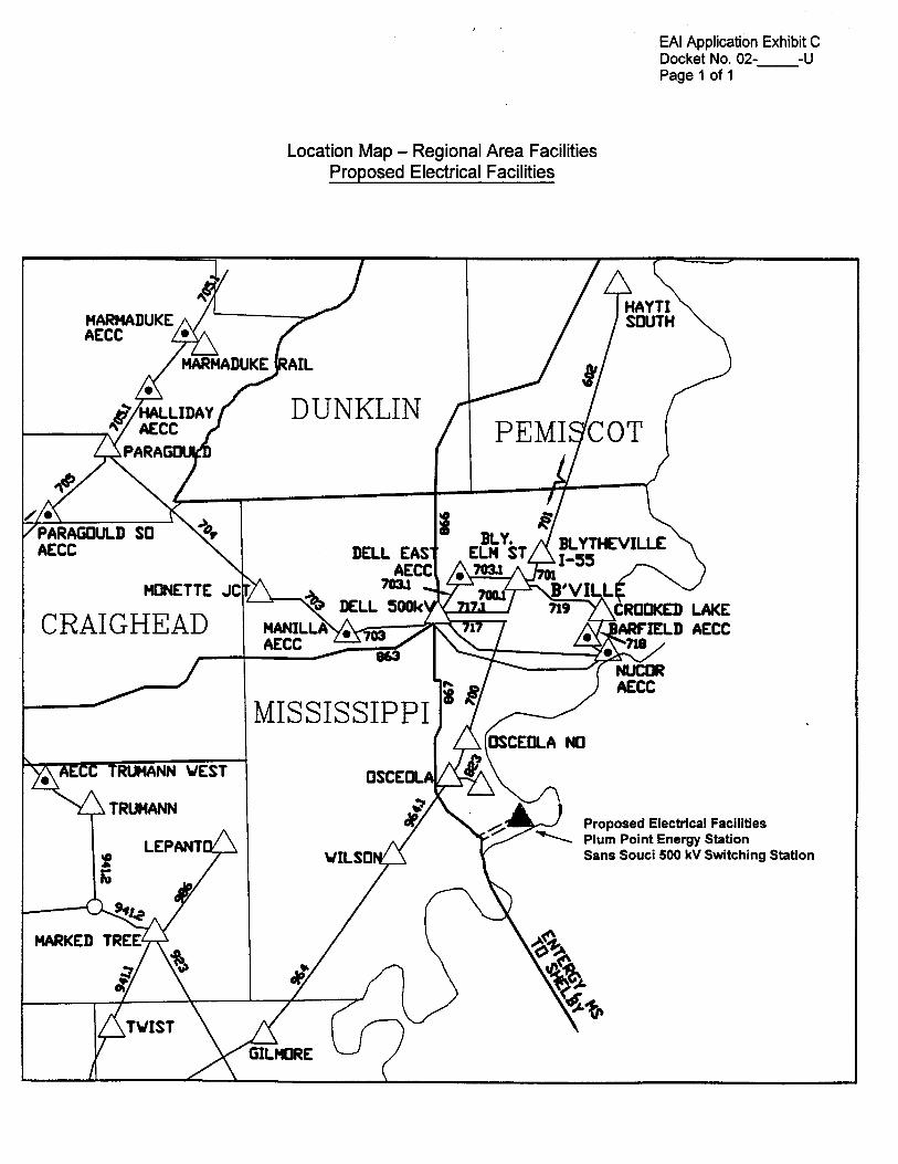
EA1 Application Exhibit C Docket No. 02- -U Page 1 of 1
Location Map - Regional Area Facilities Proposed Electrical Facilities
HONETTE JC1
CRAIGHEAD
R U W N VEST
DELL g;w7yAp BLYTHE VILLE
7034 B'VILL DELL SO& ROOKED
Proposed Electrical Facilities Plum Point Energy Station Sans Souci 500 kV Switching Station

BEFORE THE ARKANSAS PUBLIC SERVICE COMMISSION
IN THE MATER OF THE APPLICATION OF ENTERGY ARKANSAS, INC. FOR A CERTIFICATE OF ENVIRONMENTAL COMPATIBILITY AND PUBLIC NEED TO
SOUCl500 KV SWITCHING STATION AND ) RELATED 500 KV TRANSMISSION LINE ) AND ASSOCIATED TRANSMISSION FACILITIES, IN MISSISSIPPI COUNTY, ) ARKANSAS
)
CONSTRUCT AND OPERATE THE SANS 1 DOCKET NO. 02- -U
EA1 APPLICATION EXHIBIT D
DESCRIPTION - PROPOSED ELECTRICAL FACILITIES

EA1 Application Exhibit D Docket No. 02-’ - u Page 1 of 13
PROJECT DESCRIPTION
SANS SOUCl500 KV SWITCHING STATION TO
THE EXISTING DELL-SHELBY 500 KV TRANSMISSION LINE WESTERN-MOST TRANSMISSION LINE SEGMENT
SANS SOUCl500 W SWITCHING STATION TO
THE EXISTING DELL-SHELBY 500 KV TRANSMISSION LINE EASTERN-MOST TRANSMISSION LINE SEGMENT
SANS SOUCl500 KV SWITCHING STATION
1 Location - Recommended Alignment
2
3
4
5
6
7
8
9
10
11
12
This project, located in Mississippi County, Arkansas, consists of a total of two
new 500 kV transmission line segments, approximately 1.5 miles (7,800 ft.) in length,
connecting to the existing 500 kV Dell Substation to Shelby 500 kV Substation
Transmission line (“Dell-Shelby 500 kV Transmission Line”), and the construction of a
new 500 kV Switching Station (“Sans Souci 500 kV Switching Station”).
Western-Most 500 kV Transmission Line Segment
Beginning at the northwestern-most dead-end bay on the southwest side
of the proposed Sans Souci Switching Station, located in the N% of the
NE% of Section 24, T-I 2-N, R-I O-E, Mississippi County, Arkansas, the
proposed 500 kV line segment exits the switching station to the south and

~
1
2
3
4
5
6
7
8
9
10
11
12
13
14
15
16
17
18
19
20
21
22
EA1 Application Exhibit D Docket No. 02- - u Page 2 of 13
continues parallel to the southeast property line of the Burlington Northern
Santa Fe Railway (“BNSF”) right-of-way, being located approximately 90
feet southeast of said southeast property line of the Burlington Northern
Santa Fe Railway right-of-way. The proposed western-most line segment
continues southwest for approximately 3,700 feet (0.66 mile) where it
crosses State Highway 198. Approximately 1,500 feet (0.28 miles)
southwest of Arkansas State Highway 198, the line segment crosses
Sandy Bayou (Ditch No. 9). South of the Sandy Bayou crossing, the
western-most line segment then crosses through approximately 1 ,I 00 feet
(0.21 miles) of storage area and, at this point, parallels both the BNSF
railroad track and U.S. Highway 61. The line segment then crosses
another 1,500 feet (0.28 miles) of agricultural land before crossing farm
drainage Ditch No. 16 and intersecting with the tie-in point at a new
structure on the existing Dell-Shelby 500 kV Line located in the SE % of
the NE % of Section 26, T-12-N, R-10-E, Mississippi County, Arkansas.
Once completed this western-most line segment will become the terminal
leg of the Dell 500 kV Substation to Sans Souci 500 kV Switching Station
Transmission Line. Total length is approximately 7,800 feet (1.5 miles).
Eastern-Most 500 kV Transmission Line Segment
Beginning at the southeastern-most dead-end bay on the southwest side
of the DroDosed Sans Souci Switchina Station. located in the N% of the

~
1
2
3
4
5
6
7
8
9
10
1 1
12
13
14
15
16
17
18
19
20
21
EA1 Application Exhibit D Docket No. 02- - u Page 3 of 13
NE% of Section 24, T-12-N, R-IO-E, Mississippi County, Arkansas, the
proposed 500 kV line segment exits the switching station to the south and
continues parallel to the southeast property line of the BNSF right-of-way
and east of the above proposed 500 kV western-most transmission line
segment, being located approximately 230 feet southeast of said
southeast property line of the BNSF right-of-way. The eastern-most line
segment continues southwest parallel to the BNSF and the proposed
western-most 500 kV line segment for approximately 7,800 feet (1.5
miles), crossing Arkansas State Highway 198, Sandy Bayou (Ditch No. 9)
and Ditch No. 16, and then intersects with the tie-in point at a new
structure on the existing Dell-Shelby 500 kV Line located in the SE % of
the NE % of Section 26, T-12-N, R-IO-E, Mississippi County, Arkansas.
Once completed this line segment will become the initial leg of the Sans
Souci 500 kV Switching Station to Shelby 500 kV Substation
Transmission Line. Total length is approximately 7,800 feet (1.5 miles).
Location - Alternative
An alternate transmission line route to the east measures approximately
3.1 miles (16,500 feet) to connect to the Dell-Shelby 500 kV Transmission
Line. This route requires that the proposed 500 kV Switching Station site
be relocated to the east of the preferred site and northeast of Arkansas
22 State Highways 239 and 198. The alternate route parallels drainage

1
2
3
4
5
6
7
8
9
10
11
12
13
14
15
16
17
18
19
20
21
22
EA1 Application Exhibit D Docket No. 02- - u Page 4 of 13
ditches for the most of the way and begins at the alternate Sans Souci
500 kV Switching Station site located in the SEX of the SEX of Section
18 at T-12-N, R-11-E, Mississippi County, Arkansas. The alternate 500
kV line segments will exit the proposed alternate Sans Souci 500 kV
Substation site to the west and will cross over Brown Bayou and Arkansas
State Highway 239 while running parallel and to the north of the BNSF rail
spur for approximately 3,400 feet (0.6 mile). It then makes a 90-degree
turn to the south at an unnumbered farm ditch. The alternate route then
extends to the south for approximately 10,500 feet (2.0 miles) while
paralleling a portion of Ditch No. 10 and crossing Sandy Bayou (Ditch No.
9) - At the intersection of the south section line of Section 30, the route
then makes a 90-degree turn to the west. It proceeds west along the
section line for approximately 1,200 feet (0.2 mile), where it makes
another 90-degree turn, and proceeds due south for approximately 1,400
feet (0.3 mile) to intersect with EAl’s existing Dell-Shelby 500 kV
Transmission Line located in the NEX of the NE% of Section 36, T-12-N,
R-I 0-E, Mississippi County, Arkansas.
Structures
The 500 kV overhead, three-phase, shielded, single circuit electrical
transmission lines will be sumorted bv two and three Dole. steel structures. These

EA1 Application Exhibit D Docket No. 02- - u Page 5 of 13
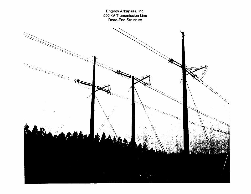
1 structures will consist of tangent structures and guyed dead-end structures. The
2 attached photographs show the general appearance of these structures. The proposed
3 lines will consist mostly of tangent structures with dead-end structures at each end of
4 each segment. All structures will meet or exceed requirements of the National
5 Electrical Safety Code (‘“ESC”) with applicable overloads.
6 The 500 kV tangent structures will be a two pole, H-frame type structures
7 designed to meet the loading requirements specified above, varying in height
8
9
10
11
12
13
14
15
16
17
18
19
20
21
22
depending on clearance requirements. Each of the three phases will be supported by
polymer V-string insulators, one set of V-string insulators per phase, approximately 14
feet long. The phases will be in a horizontal (flat) configuration on both sections of the
new lines. Each of the 500 kV line segments will have two shield wires supported by
hardware located near the pole tops. The poles will be attached to cylindrical concrete
caisson type foundation embedded in the earth at varying depths depending on soil
conditions and foundation loads. Depending on soil conditions, alternate foundations
such as 20 to 30 foot long piles may be required.
The 500 kV large angle and dead-end structures will be a 3-pole, designed to
meet the specified loading conditions, varying in length, with a polymer post insulator to
support the conductor connections around the pole if required by the line angle. The
shield wire and conductors will be attached directly to the pole with connecting
hardware. Down guys will be utilized as necessary to accommodate the transverse and
longitudinal loads imposed by the conductors and shield wires and to provide structural
stability. Down guys will be attached to an anchoring system designed to
EA1 Application Exhibit D Docket No. 02- - u Page 6 of 13
1
2
3
4
5
6
7
8
9
10
11
12
13
14
15
16
17
accommodate the guy loads and the soil conditions. The poles will be attached to
cylindrical concrete caisson type foundation embedded in the earth at varying depths
depending on soil conditions and foundation loads.
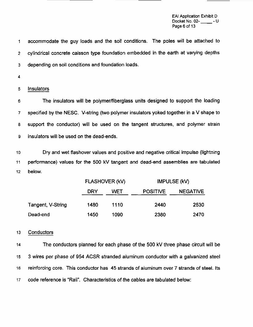
Insulators
The insulators will be polymer/fiberglass units designed to support the loading
specified by the NESC. V-string (two polymer insulators yoked together in a V shape to
support the conductor) will be used on the tangent structures, and polymer strain
insulators will be used on the dead-ends.
Dry and wet flashover values and positive and negative critical impulse (lightning
performance) values for the 500 kV tangent and dead-end assemblies are tabulated
below.
FLASHOVER (kv) IMPULSE (kv)
DRY WET POSITIVE NEGATIVE
Tangent, V-String 1480 1110 2440 2530
Dead-end 1450 1090 2380 2470
Conductors
The conductors planned for each phase of the 500 kV three phase circuit will be
3 wires per phase of 954 ACSR stranded aluminum conductor with a galvanized steel
reinforcing core. This conductor has 45 strands of aluminum over 7 strands of steel. Its
code reference is “Rail”. Characteristics of the cables are tabulated below:

EA1 Application Exhibit D Docket No. 02- - u Page 7 of 13
Physical Characteristics
Outside diameter, inches
Weight, pounds per foot
Ultimate strength, pounds
Electrical resistance, ohm per mile
Inductive reactance, ohm per mile
Capacitive reactance, megohm-mile
1.165
1.076
25,900
0.1094
0.395
0.0897
Installation Characteristics
NESC Heavy loading tension, pounds
60" F. unloaded tension after 10 years, pounds
10,000
4,066
I
2 tabulated below:
The overhead shield wire will be a 7 No. 7 Alumoweld. Characteristics of the cable are
P hvsical Characteristics
Outside diameter, inches
Weight, pounds per foot
Ultimate strength, pounds
Installation Characteristics
NESC medium loading tension, pounds
0.433
0.330
19,060
3,425
1,448 60" F. unloaded tension after loading, 10 years
EA1 Application Exhibit D Docket No. 02- - u Page 8 of 13
1
2
3
4
5
6
7
8
9
10
11
12
13
14
15
16
17
18
19
20
21
22
The spans for the 500 kV line will average between 600 and 1100 feet. The
minimum conductor to ground for the 500 kV line will be 40 feet. Where electrical
distribution or communication lines are crossed, a clearance of 20 feet will be
maintained for a conductor operating temperature of 176" F. The 500 kV spans
crossing the railroad will have a minimum conductor to top of rail clearance of 45 feet.
Terminal Point - Sans Souci 500 kV Switching Station
The proposed Sans Souci 500 kV Switching Station facility will be a new 500 kV, 4
breaker switching station constructed immediately adjacent to the Plum Point Energy
Station site, on property to be provided by Plum Point Energy Associates, LLC
("PPEA"). This switching station will be owned and operated by EAI. The switching
station will be configured as a "ring-bus" with 3-phase gas-insulated 5-inch aluminum
pipe bus arranged in a horizontal configuration. Bus phases will be spaced 30 feet apart
horizontally. The proposed switching station will be designed as a low profile facility.
The tallest structures within the fenced switching station will be the dead-end structures
for the 500 kV transmission line terminations and takeoffs, and the lightning shielding
structures. These structures should not exceed 100 feet in height.
The Sans Souci 500 kV Switching Station will have four separate line positions in
the ring bus. One line segment in-coming and one line segment out-going fromlto the
existing EA1 Dell-Shelby Transmission Line, and two lines connecting the PPEA power
plant output feeds. Each line position will be protected by a set of two, 500 kV power
circuit breakers (Le. there will be one circuit breaker between each line position, for a
EA1 Application Exhibit D Docket No. 02- - u Page 9 of 13
1
2
3
7
8
9
10
11
12
13
14
15
16
17
18
19
20
total of four breakers), in what is commonly called a “ring-bus” protection scheme. A set
of two motor-operated disconnect switches will be installed at each breaker (one on
each side) to provide isolation ability.
A dedicated relay and control building will be constructed in the switching station
to house the power, controls, and monitoring equipment required to operate the
substation locally. Cables to/from the control house to the various equipment
components will be routed via direct buried conduit duct banks and in engineered cable
trenches. Communications between the Sans Souci 500 kV switching Station and the
Dell 500 kV Substation and the Shelby 500 kV Substation will be transmitted via carrier
wave signals on the 500 kV transmission line conductors.
All structures and equipment in the Sans Souci 500 kV Switching Station (with
the exception of the circuit breakers) will be supported on augured pier concrete
foundations. The circuit breakers will be supported on concrete pad foundations.
Equipment and bus within the substation will be supported on galvanized tubular steel
structures, connected via embedded anchor bolts to the augured pier foundations
described above. The entire switching station site will be fenced with an 8-foot chain
link fence. Emergency lighting will be provided in the event maintenance must occur at
night.
Construction
21
22
The proposed facilities will be designed by Entergy Services, Inc. (“ESI”)
personnel for EA1 and construction will be accomplished by pre-qualified electrical

EA1 Application Exhibit D Docket No. 02- - u Page 10 of 13
1
8
9
10
11
12
13
14
15
16
17
18
19
20
21
contractor crews under the supervision of ESI personnel in a sequential operation of
surveying, clearing, foundation installation, structure erection, conductor installation and
clean-up.
The first operation is to survey the route to establish the centerline, edge of right-
of-way, and profile of the transmission line. Primarily, only men and small items of
equipment will be required for surveying. Centerline staking and profiling may require
cutting some trees and undergrowth, if necessary. No new access roads will be
established for survey crews.
Right-of-way clearing, if necessary, will be performed by EA1 construction crews
or by a contractor under the supervision of EA1 personnel to ensure that the clearing is
done as specified. Trees that may exist outside of the right-of-way which endanger the
safe and reliable operation of the transmission line will be cut to provide necessary
clearance.
Structure installation takes place in three phases: transporting, assembling, and
erecting. Necessary material is transported by flatbed tractor-trailer from a storage yard
to each structure location and is unloaded with a small crane or boom truck. The
structures are assembled, as much as is practical, on the ground; the poles are then set
in augured holes with a tracked or rubber-tired crane. The holes will be backfilled with
concrete. Final hardware connections will then be completed.
Conductor stringing is accomplished with tensioning equipment to keep the
conductor from contacting the ground or other objects which may damage it. A pulling
22 line is installed on the structures in stringing blocks from a puller to the tensioner. The
EA1 Application Exhibit D - U Docket No. 02-
Page 11 of 13
1 reels of conductor are mounted on reel stands and the conductor is threaded through
2 the tensioner and attached to the pulling line. The puller operates to pull the conductor
3 while the tensioner operates to maintain the proper tension.
4 Conductor installation is a critical operation. Many vehicles and items of
5 equipment are required to install the conductor; and, although they may not necessarily
6 proceed down the right-of-way, they must intermittently be positioned on it. As with
7 vehicles and equipment associated with other construction phases, care will be
8 exercised to minimize damage to the terrain.
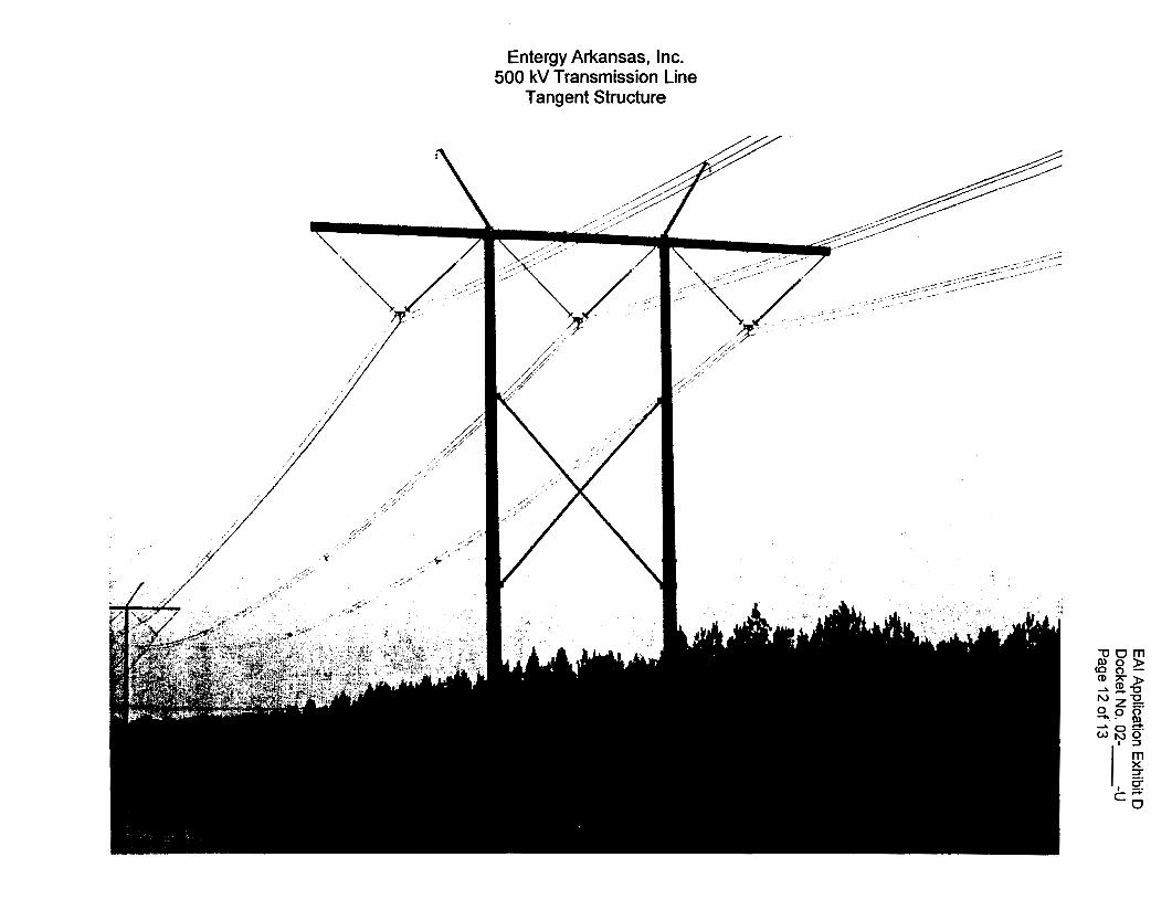
Entergy Arkansas, Inc. 500 kV Transmission Line
Tangent Structure

Entergy Arkansas, Inc. 500 kV Transmission Line
Dead-End Structure

BEFORE THE ARKANSAS PUBLIC SERVICE COMMISSION
IN THE MATTER OF THE APPLICATION 1 OF, ENTERGY ARKANSAS, INC. FOR A 1 CERTIFICATE OF ENVIRONMENTAL 1 COMPATIBILITY AND PUBLIC NEED TO 1 CONSTRUCT AND OPERATE THE SANS ) SOUCl500 KV SWITCHING STATION AND ) RELATED 500 KV TRANSMISSION LINE ) AND ASSOCIATED TRANSMISSION 1 FACILITIES, IN MISSISSIPPI COUNTY, ) ARKANSAS 1
DOCKET NO. 02- -U
APPLICATION EXHIBIT E
CERTIFICATION OF PROOF OF SERVICE
BEFORE THE ARKANSAS PUBLIC SERVICE COMMISSION
IN THE MATTER OF THE APPLICATION ) OF ENTERGY ARKANSAS, INC. FOR A ) CERTIFICATE OF ENVIRONMENTAL ) COMPATIBILITY AND PUBLIC NEED TO ) CONSTRUCT AND OPERATE THE SANS 1 DOCKET NO. 02- -U SOUCl500 KV SWITCHING STATION AND ) RELATED 500 KV TRANSMISSION LINE 1 AND ASSOCIATED TRANSMISSION 1 FACILITIES, IN MISSISSIPPI COUNTY, ) ARKANSAS 1
CERTIFICATION OF PROOF OF SERVICE
I, Steven K. Strickland - Vice President, Regulatory Affairs -- Arkansas,
for Entergy Arkansas, Inc. - certify that pursuant to Rules 7.09 of the Rules of
Practice and Procedure of the Arkansas Public Service Commission and Ark.
Code Ann. § 23-18-513, each government official on the attached list was served
notice of the filing of the Application in this Docket by certified mail or personal
delivery. A representative copy of the letter of notification of the Application
filing, including a route location map and photograph copies of the structures to
be installed, also is attached.
Additionally I certify that pursuant to Rules 3.03(~)(2) of the Rules of
Practice and Procedure of the Arkansas Public Service Commission, each
person on the attached landowner list was served notice of the filing of the
Application in this Docket by first class mail. A representative copy of the form
letter of notification of the Application filing, including a route location map and a
representative photograph copy of the structures to be installed are filed in - EA1
Exhibit MKW-1 in the Direct Testimony of Company witness Murry K. Witcher.
Vice President, Regulatory Affairs Entergy Arkansas, Inc.
- 2 -

m -Entwgy m
Entergy Arkansas, Inc. 425 Wes? Capitol Avenue P.O. Box 551 Little Rock, AR 72203-0551 Tel 501 377 4457 Fax 501 377 4415
March 28,2002 Steven K. Strickland Vice President Regulatory Affairs
[ Dept. Name ] r I r I
Re: Proposed 500 kV Sans Souci Switching Station and 500 kV Transmission Lines
IN THE MATTER OF THE APPLICATION OF ENTERGY ARKANSAS, INC. FOR A CERTIFICATE OF ENVIRONMENTAL COMPATIBILITY AND PUBLIC NEED TO CONSTRUCT AND OPERATE THE SANS SOUCl500 KV SUBSTATION AND RELATED 500 KV TRANSMISSION LINE AND ASSOCIATED TRANSMISSION FACILITIES, IN MISSISSIPPI COUNTY, ARKANSAS
Dear [ Title Name 1:
This is to inform you pursuant to Ark. Code Ann. 8 23-18-513 and Rule 3.03(b)(3) and 7.09 of the Arkansas Public Service Commission (APSC) Rules of Practice and Procedure, that on or about Thursday, March 28, 2002 (the Application Filing Date), Entergy Arkansas, Inc. (EM) filed an application with the APSC for permission to construct a 500,000 volt electric transmission line and a related 500 kV switching station (Proposed Electrical Facilities) in Mississippi County, Arkansas. The Proposed Electrical Facilities consist of:
a four-element, 500 kV ring-bus switching station which terminates two generator output source feeds from a new generating station and connects with the EA1 transmission grid through two parallel 500 kV transmission line segments that extend south from the switching station for a total of approximately 1.5 miles (7,800 ft.) located in Sections 24 and 26 in Township 12 North (T-l2-N), Range 10 East (R-lO-E), Mississippi County, Arkansas.
The Proposed Electrical Facilities are more fully described as follows.
Sans Souci 500 kV Switching Station - The proposed Sans Souci 500 kV Switching Station will be a new 500 kV, 4 breaker ring-bus switching station constructed on property immediately adjacent to and westlsouthwest of the Plum Point Energy Station, on property to be provided by Plum Point Energy Associates, LLC (PPEA). This switching station will be owned and operated by EAI. The switching station design will be configured as a "ring-bus" with 3-phase
Letter of Notice (con?) March 28,2002
gas-insulated 5-inch aluminum pipe bus arranged in a horizontal configuration. Bus phases will be spaced 30 feet apart horizontally.
The Sans Souci 500 kV Switching Station will have four separate line positions in the ring-bus. One line segment in-coming and one line segment out-going fromlto the EA1 Dell 500 kV Substation to Shelby 500 kV Substation Transmission Line (Dell-Shelby 500 kV Transmission Line), and two lines connecting the Plum Point Energy Station output feeds. Each line position will be protected by a set of two, 500 kV power circuit breakers (i.e. there will be one circuit breaker between each line position, for a total of four breakers), in what is commonly called a "breaker and a halt" protection scheme. A set of two motor-operated disconnect switches will be installed at each breaker (one on each side) to provide isolation ability.
A dedicated relay and control building will be constructed in the switching station to house the power, controls, and monitoring equipment required to operate the switching station locally. Cables tolfrom the control house to the various equipment components will be routed via direct buried conduit duct banks and in engineered cable trenches. Communications between the Sans Souci 500 kV Switching Station and the Dell 500 kV Substation and the Shelby 500 kV Substation will be transmitted via carrier wave signals on the 500 kV transmission line conductors.
Sans Souci 500 kV Switching Station to the Existing DellShelby 500 kV Transmission Line - The proposed two parallel line segments to be connected from the Sans Souci 500 kV Switching Station to the Dell-Shelby 500 kV Transmission Line, begin at the proposed EA1 Sans Souci 500 kV Switching Station, located in the N% of the NE% of Section 24 in T-12-N, R-lO-E, and exit the switching station to the south and extend southwest for approximately 1.5 miles (7,800 feet) paralleling the southeast property line of the Burlington Northern Santa Fe Railway (BNSF) right-of-way. The two parallel 500 kV transmission line segments are located approximately 90 feet and approximately 230 feet southeast of said southeast property line of the BNSF right-of-way. The proposed 500 kV line segments continue southwest along the BNSF, crossing Arkansas State Highway 198, Sandy Bayou (Ditch No. 9) and Ditch No. 16, and then intersect with the tie-in structure at the existing Dell-Shelby 500 kV Transmission Line located in the SE % of the NE % of Section 26, T-12-N, R-10- E, Mississippi County, Arkansas.
Information related to the Company's application may be obtained from the Secretary of the APSC, 1000 Center Street, Little Rock, Arkansas 72201, during normal business hours. A copy of the Application and related filing documents along with the Environmental Impact Statement associated with this proposed project is included in this notice for your inspection.
The enclosed map portrays the approximate location of the proposed transmission segment routes and the proposed switching station. The sites were selected after careful environmental, economic and engineering consideration. Also enclosed are drawings of the typical transmission line structures that illustrate the appearance of the tubular steel pole structures to be used in the construction of this line.
- 2 -

Letter of Notice (con’t) March 28,2002
The APSC will conduct a hearing in connection with EAI’s Application for a Certificate of Environmental Compatibility and PubIic Need. Interventions and limited appearances for interested persons should be in compliance with provisions of APSC Rule 3.04 and Ark. Code Ann. f j 23-18-517. Petitions for intervention or limited appearance must be filed with the APSC within 30 days after the Application Filing Date unless good cause is shown pursuant to Ark. Code Ann. f j 23-1 8-5 17.
A public hearing date will be set by the APSC not less than 40 days nor more than 90 days after the Application Filing Date. The public hearing will be held at the APSC Building in Little Rock, Arkansas, located at 1000 Center Street. The purpose of the hearing will be for the Commission to hear evidence of the general economic and environmental impact of the proposed project, and to choose the best location with the least generally adverse economic and environmental consequences. In the course of selecting a route location for the proposed transmission facilities, the Commission may modify the proposed location if it is in the public interest. Compensation for any damages will not be awarded by the Commission, but may be awarded by Circuit Court in an eminent domain proceeding, if the applicant and the landowner cannot settle privately.
I would be pleased to provide any additional information you may need concerning the Proposed Electrical Facilities. My telephone number is (50 1) 377-4457.
Sincerely yours,
Steven K. Strickland Vice President, Regulatory Affairs - Arkansas
Enclosures
- 3 -


Entergy Arkansas, Inc. 500 kV Transmission Line
Tangent Structure
///
Entergy Arkansas, Inc. 500 kV Transmission Line
Dead-End Structure

Government Officials and Agency List
Name Title Add1 1 Add2
The Honorable Dickie Kennemore The Honorable Mike Wilson The Honorable Lloyd Brinkley The Honorable Barrett (Barry) Harrison The Honorable Melvin Browning
Mayor of Osceola Mayor of Wilson 1 Park Mayor of Luxora Mayor of Blytheville Mayor of Manila
P.O. Box 443
107 S. Main 121 N. 2nd P.O. Box 895
The Honorable Lawrence W. Ashlock The Honorable David Fletcher I Mavor of Monette I P.0.382
i Mayor of Marked Tree I #1 Elm St. 4
Mayor of Gosnell The Honorable Dick Reams
Robert Earl Davis
~
307 South Airbase
The Honorable Bill Gibson
Governor
The Honorable Kevin Goss The Honorable Marvin Childers The Honorable Wayne Nichols
State Capitol The Honorable Steie Bryles The Honorable Mike Huckabee
Mr. Richard Weiss
Mr. Jim Pickens
Mr. Hugh Durham
Mr. Charlie Daniels
Mr. Richard W. Davies
Mr. Morris Jenkins
Acting Director Department of
Director Economic Environmental Quality
Development Commission
Fish Commission
Commissioner of Lands Department of Parks
Director Arkansas Game and
Commissioner Arkansas State
Director, Parks and Tourism & Tourism Director Arkansas Energy
Office
Chairman, Planning and I Mississippi County Development Committee State Rep District 92
State Rep District 94 State Rep District 93 State Reu District 89
Quorum Court 5020 Highway 13 9 south 26 Union St. 608 So. Estate Street 304 Poinsett St.
I
State SeAator District 28 I 514 West Main
City
Osceola, AR 72370 Wilson, AR 72395 Luxora, AR 72358 Blytheville, AR 723 15 Manila,AR 72442
200 West Walnut, Room 204
Blytheville, AR 723 15
Monette, AR 72447
Wilson, AR 72395 Blytheville, AR 723 15 Marked Tree, AR 72365 Blytheville, AR 723 15 Little Rock, AR 72201
Little Rock, AR 722 19- 8913 Little Rock, AR 72201
Governor’s Ofice Rm 250 P.O. Box 8913
One Capitol Mall
#2 Natural Resources Drive 109 State Capital
Little Rock, AR 72205
Little Rock. AR 72201
1 Capitol Mall, Room 4A-900 7220 1 # 1 State Capitol Mall
Little Rock, Arkansas
Little Rock, AR 7220 1
Page 1

Government Officials and Agency List
I I I I I City I Add2 I Add1 I Name Title I
Steve McGuire
Mr. Eldon Fairley
Dr. Fay Booman
Mr. Dan Flowers
Ms. Cathie Matthews
The Honorable Mark Pryor J. Randy Young, P.E.
Mr. Dick Barclay
Mississippi County Judge
Chairman, Osceola Planning Commission Director
Director
Director
Attorney General Executive Director
Director
I
Blytheville, AR 723 15
Osceola, AR 72370
Little Rock, AR 72205
Mr. John Knight
Mississippi County Courthouse 3 16 W. Hale Avenue
Director
Arkansas Department of Health Arkansas Highway & Transportation Department Arkansas Heritage Department 200 Tower Building Arkansas Soil and Water Conservation Commission Department Finance & Administration Arkansas Department of Aeronautics State Forestry Commission Corps of Engineers, Little Rock District Arkansas Public Service Commission Staff
Mr. John Shannon
200 W. Walnut
State Forester
48 15 West Markham St. 10324 Interstate 30
323 Center Street 1500 Tower Bldg 323 Center Street 101 E. Capitol, Suite 350
1509 W. Seventh Street 1 Airport Drive, 3rd Floor 382 1 West Roosevelt
P.O. Box 867
P.O. Box 400 1000 Center St.
Little Rock, AR 72209
Little Rock, AR 72201
Little Rock, AR 72201 Little Rock, AR 72201
Little Rock, AR 72201
Little Rock. AR 72202
Little Rock, AR 72204
Little Rock, AR 72203- 0867 Little Rock, AR 72203
Page 2