swagelok.com thread and end connection
TRANSCRIPT

Thread and End ConnectionIdent i f icat ion Guide
swagelok.com


Table of Contents
IntroductionThread and End Connection Terminology . . . . . . . . . . 5
General Terminology . . . . . . . . . . . . . . . . . . . . . . . . . . . 6
Step-by-Step Identification Procedure for Threads and End Connections . . . . . . . . . . . . . . . . . . . . . . . 7
Thread Identification Reference Tables . . . . . . . . . . . . . . . . . . . . . . .13
Tapered Threads . . . . . . . . . . . . . . . . . . . . . . . .21End Connections That Use:
Tapered Threads . . . . . . . . . . . . . . . . . . . . . . . . . . . . . 23
Straight Threads . . . . . . . . . . . . . . . . . . . . . . . .27End Connections That Use:
Unified Screw Threads . . . . . . . . . . . . . . . . . . . . . . . . 29
ISO 228/1 Threads . . . . . . . . . . . . . . . . . . . . . . . . . . . . 36
Metric (ISO 261) Threads . . . . . . . . . . . . . . . . . . . . . . . 43
NPSM Threads . . . . . . . . . . . . . . . . . . . . . . . . . . . . . . . 50
AppendixEnd Connection to Thread Matrix . . . . . . . . . . . . . . . . 51
Thread to End Connection Matrix . . . . . . . . . . . . . . . . 52
Thread Identification Tools . . . . . . . . . . . . . . . . . . . . . 53
Glossary . . . . . . . . . . . . . . . . . . . . . . . . . . . . . . . . . . . . 54

4
Iden
tifica
tion
Tables
Tape
red
Straight
Introd
uctio
nAp
pend
ix
About Swagelok CompanySwagelok Company is an approximately $2 billion privately held developer of fluid system products, assemblies, and services for the oil and gas, chemical and petrochemical, semiconductor, and transportation industries . Headquartered in Solon, Ohio, U .S .A ., Swagelok serves customers through 200 sales and service centers in 70 countries, supported by the expertise of 5,500 corporate associates at 20 manufacturing facilities and five global technology centers .
For more information or assistance please contact your authorized Swagelok sales and service center or visit our website at www .swagelok .com .
5
IdentificationTables
TaperedStraight
IntroductionAppendix
Introduction
Thread and End Connection TerminologyStandards are used to help identify threads and end connections . We will use the following definitions in this manual:
Thread StandardA specific reference to a formal standard (for example, ASME B1 .1, EN 10226-1, or ISO 261) that describes thread form, including a thread’s angle, pitch, and diameter .
End Connection StandardA specific reference to a national standard (such as DIN 3852 or JIS R and JIS Rc) or industry group standard (such as SAE J512) that describes an end connection’s components, seal area, geometry, and nominal sizes . Thread standards are usually referenced in the end connection standard .
Thread Standards and End Connection StandardsMany mechanical end connections have threads . Therefore, thread standards can be used to help define end connection standards .
PitchFor the purposes of this guide, pitch refers to threads per inch, instead of the distance between the threads, for fractional screw threads and pipe threads . For all metric screw threads, pitch refers to the distance between adjacent threads .
6
Iden
tifica
tion
Tables
Tape
red
Straight
Introd
uctio
nAp
pend
ix
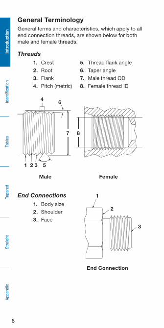
General TerminologyGeneral terms and characteristics, which apply to all end connection threads, are shown below for both male and female threads .
Threads1. Crest 5. Thread flank angle
2. Root 6. Taper angle
3. Flank 7. Male thread OD
4. Pitch (metric) 8. Female thread ID
End Connections1. Body size
2. Shoulder
3. Face
Male Female
End Connection
1
2
3
1 2 3 5
4 6
7 8
7
IdentificationTables
TaperedStraight
IntroductionAppendix
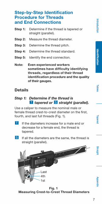
Fig. 1 Measuring Crest-to-Crest Thread Diameters
Last4th1st
Step-by-Step Identification Procedure for Threads and End ConnectionsStep 1: Determine if the thread is tapered or
straight (parallel) .
Step 2: Measure the thread diameter .
Step 3: Determine the thread pitch .
Step 4: Determine the thread standard .
Step 5: Identify the end connection .
Note: Even experienced workers sometimes have difficulty identifying threads, regardless of their thread identification procedure and the quality of their gauges.
Details
Step 1: Determine if the thread is T tapered or S straight (parallel).
Use a caliper to measure the nominal male or female thread crest-to-crest diameter on the first, fourth, and last full threads (Fig . 1) .
T If the diameters increase for a male end or decrease for a female end, the thread is tapered .
S If all the diameters are the same, the thread is straight (parallel) .

8
Iden
tifica
tion
Tables
Tape
red
Straight
Intro
duction
Appe
ndix
Fig. 2 Measuring the Thread Diameters
T
S
Last 4th 1st
Last 4th 1st
Step 2: Measure the thread diameter.Use a caliper to measure the nominal male or female thread diameter from crest-to-crest (Fig . 2) .
T Measure the fourth or fifth full thread .
S Measure any full thread .
The diameter measurement obtained in this step may not be exactly the same as the listed nominal size for the given thread . The main reason for this variation is industry or manufacturing tolerances .
Step 3: Determine the thread pitch.To determine the thread pitch, use the Swagelok® pitch gauges and check the thread against each form until you find a match . If you prefer to narrow down the choices, use the following procedure:
a . On the appropriate thread identification reference table, locate the nominal thread diameter . Note that it is common to have the thread diameter for different threads listed multiple times .
T Turn to the Tapered Thread Identification Reference Tables beginning on page 13 .
S Turn to the Straight Thread Identification Reference Tables beginning on page 15 .

9
IdentificationTables
TaperedStraight
IntroductionAppendix
b . For each case, read across the table to the pitch column to determine the possible thread pitches for your thread .
c . Try the appropriate pitch gauge form for the threads identified in Step b . above until you find a match (Fig . 3) .
1 .5 mm per thread
18 threads per inch
No Match Match
Fig. 3. Determining the Thread Pitch
Step 4: Determine the thread standard.Once you have determined the following about a thread, you have all the information required to identify it:■Male or female■Straight or tapered■Nominal male or female diameter■Pitch
Now, turn to the appropriate thread identification reference table and identify the thread .
Step 5: Identify the end connection.
T If the thread is tapered:
a . Locate the end connections that have the tapered thread you identified . (See pages 21 through 26 .
b . Study the cross-section drawings for these end connections and determine which one matches your end connection .

10
Iden
tifica
tion
Tables
Tape
red
Straight
Intro
duction
Appe
ndix
Fig. 4 Determining Seat Angle
Note: Fittings have seat angles other than 45°, 37°, and 30°. Contact your authorized Swagelok sales and service center for additional information.
Longitudinal axis
Center line
No Match
Seat gauge angle
Seat angle
Match
S If the thread is straight:
a . Locate the end connections that use the straight thread you identified . (See pages 27 through 50 .
b . Study the cross-section drawings for these end connections and determine which one matches your end connection .
Note: The Swagelok combination seat and pitch gauge set includes 45°, 37°, and 30° seat angle gauges to assist with end connection identification. (See page 53.)
c . Select one of the gauges and place its angle against the seat angle of the end connection .
d . If the center line of the fitting and the longitudinal axis of the gauge are parallel, the seat angle and the gauge angle are the same . If not, try another gauge .

11
IdentificationTables
TaperedStraight
IntroductionAppendix
EXAMPLE: Thread and End Connection Identification (Steps 1 to 5)
You have a male fitting and you need to identify its thread .
Step 1: Determine if the thread is tapered or straight (parallel).
You find that the thread is straight .
Step 2: Measure the thread diameter.
You find the thread diameter to be 0 .430 in .
Step 3: Determine the thread pitch.
a . Because the thread is straight, turn to the Straight Thread Identification Reference Table, page 15, and locate the thread diameter . See section of table below .
➀ U = Unified W = Whitworth M = Metric Labeling on each Swagelok pitch gauge form
b . Look across the table to find the corresponding pitches . In this case, they are 20 and 24 .
c . Therefore, to determine the pitch of the thread you would use your 20 and 24 pitch gauges .
For the purposes of this example, assume that the pitch is 24 .
NominalThread
Size Designation
Nominal MaleThread Diameter
Pitch➀ Pagein . mm
3/8
UNF 0 .375 to 0 .363 9 .53 to 9 .22 24U 30 to 35
NPSM 0 .658 16 .71 18U 51
ISO 228/1 0 .656 16 .66 19W 36 to 43
7/16UNS 0 .436 to 0 .429 11 .07 to 10 .90 24U 30 to 35
UNF 0 .436 to 0 .424 11 .07 to 10 .77 20U 30 to 35
1/2
UNF 0 .500 to 0 .487 12 .70 to 12 .36 20U 30 to 35
NPSM 0 .818 20 .78 14U 51
ISO 228/1 0 .825 20 .96 14W 36 to 43

12
Iden
tifica
tion
Tables
Tape
red
Straight
Intro
duction
Appe
ndix
Step 4: Determine the thread standard.
At this point you know that the thread has the following characteristics:
a . Male
b . Straight
c . Nominal thread diameter of 0 .430 in .
d . Pitch equals 24
Looking at the cut-out portion of the straight thread identification reference table, you see that the only thread with all of these characteristics is a 7/16 in . UNS thread .
Step 5: Identify the end connection.
So far you know that you have a 7/16 in . UNS thread . To identify the end connection, you:
a . Identify the type of seal .
b . Turn to the End Connections That Use Unified Screw Threads section in this manual (pages 29 through 35, and find the configuration that matches your end connection .
13
IdentificationTables
TaperedStraight
IntroductionAppendix
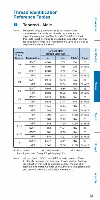
Thread Identification Reference Tables
T Tapered—MaleNote: Measured thread diameters may not match table
measurements exactly . All threads have tolerances regarding many parts of the threads . The information in this table is not intended to be used as inspection criteria for threaded fittings . It is intended to be used as a guide to help identify various threads .
➀ U = Unified W = Whitworth M = Metric Labeling on each Swagelok pitch gauge form
Note: 1/2 and 3/4 in . ISO 7/1 and NPT threads can be difficult to identify because they are very close in design . Positive identification may not be possible without the use of an optical comparator . Contact your authorized Swagelok sales and service center for additional information .
NominalThreadSize, in. Designation
Nominal MaleThread Diameter
Pitch➀ Pagein. mm
1/16ISO 7/1 0 .304 7 .72 28W 26
NPT 0 .308 7 .84 27U 24 to 25
1/8ISO 7/1 0 .383 9 .73 28W 26
NPT 0 .401 10 .18 27U 24 to 25
1/4ISO 7/1 0 .518 13 .16 19W 26
NPT 0 .533 13 .54 18U 24 to 25
3/8ISO 7/1 0 .656 16 .86 19W 26
NPT 0 .668 16 .98 18U 24 to 25
1/2ISO 7/1 0 .825 20 .96 14W 26
NPT 0 .832 21 .14 14U 24 to 25
3/4ISO 7/1 1 .041 26 .44 14W 26
NPT 1 .043 26 .49 14U 24 to 25
1NPT 1 .305 33 .14 11 .5U 24 to 25
ISO 7/1 1 .309 33 .25 11W 26
1 1/4NPT 1 .649 41 .90 11 .5U 24 to 25
ISO 7/1 1 .650 41 .91 11W 26
1 1/2ISO 7/1 1 .882 47 .80 11W 26
NPT 1 .888 47 .97 11 .5U 24 to 25
2ISO 7/1 2 .347 59 .61 11W 26
NPT 2 .362 60 .00 11 .5U 24 to 25
14
Iden
tifica
tion
Tables
Tape
red
Straight
Intro
duction
Appe
ndix
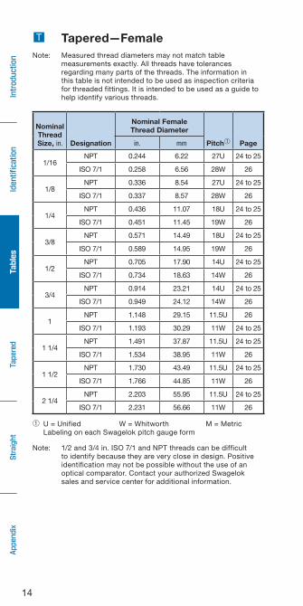
T Tapered—FemaleNote: Measured thread diameters may not match table
measurements exactly . All threads have tolerances regarding many parts of the threads . The information in this table is not intended to be used as inspection criteria for threaded fittings . It is intended to be used as a guide to help identify various threads .
➀ U = Unified W = Whitworth M = Metric Labeling on each Swagelok pitch gauge form
Note: 1/2 and 3/4 in . ISO 7/1 and NPT threads can be difficult to identify because they are very close in design . Positive identification may not be possible without the use of an optical comparator . Contact your authorized Swagelok sales and service center for additional information .
NominalThreadSize, in. Designation
Nominal FemaleThread Diameter
Pitch➀ Pagein. mm
1/16NPT 0 .244 6 .22 27U 24 to 25
ISO 7/1 0 .258 6 .56 28W 26
1/8NPT 0 .336 8 .54 27U 24 to 25
ISO 7/1 0 .337 8 .57 28W 26
1/4NPT 0 .436 11 .07 18U 24 to 25
ISO 7/1 0 .451 11 .45 19W 26
3/8NPT 0 .571 14 .49 18U 24 to 25
ISO 7/1 0 .589 14 .95 19W 26
1/2NPT 0 .705 17 .90 14U 24 to 25
ISO 7/1 0 .734 18 .63 14W 26
3/4NPT 0 .914 23 .21 14U 24 to 25
ISO 7/1 0 .949 24 .12 14W 26
1NPT 1 .148 29 .15 11 .5U 26
ISO 7/1 1 .193 30 .29 11W 24 to 25
1 1/4NPT 1 .491 37 .87 11 .5U 24 to 25
ISO 7/1 1 .534 38 .95 11W 26
1 1/2NPT 1 .730 43 .49 11 .5U 24 to 25
ISO 7/1 1 .766 44 .85 11W 26
2 1/4NPT 2 .203 55 .95 11 .5U 24 to 25
ISO 7/1 2 .231 56 .66 11W 26

15
IdentificationTables
TaperedStraight
IntroductionAppendix
S Straight—MaleNote: Measured thread diameters may not match table
measurements exactly . All threads have tolerances regarding many parts of the threads . The information in this table is not intended to be used as inspection criteria for threaded fittings . It is intended to be used as a guide to help identify various threads .
➀ U = Unified W = Whitworth M = Metric Labeling on each Swagelok pitch gauge form
(continued on next page)
NominalThread
Size Designation
Nominal MaleThread Diameter
Pitch➀ Pagein. mm
Fractional, in.
1/16 ISO 228/1 0 .304 7 .72 28W 36 to 42
1/8ISO 228/1 0 .383 9 .73 28W 36 to 42
NPSM 0 .394 10 .01 27U 50
1/4ISO 228/1 0 .518 13 .16 19W 36 to 42
NPSM 0 .522 13 .26 18U 50
5/16UNF 0 .313 to 0 .301 7 .95 to 7 .77 24U 30 to 35
UN 0 .313 to 0 .305 7 .95 to 7 .75 28U 30 to 35
3/8
UNF 0 .375 to 0 .363 9 .53 to 9 .22 24U 30 to 35
NPSM 0 .658 16 .71 18U 50
ISO 228/1 0 .656 16 .66 19W 36 to 42
7/16UNS 0 .436 to 0 .429 11 .07 to 10 .90 24U 30 to 35
UNF 0 .436 to 0 .424 11 .07 to 10 .77 20U 30 to 35
1/2
UNF 0 .500 to 0 .487 12 .70 to 12 .36 20U 30 to 35
NPSM 0 .818 20 .78 14U 50
ISO 228/1 0 .825 20 .96 14W 36 to 42
9/16 UNF 0 .563 to 0 .548 14 .29 to 13 .92 18U 30 to 35
5/8UNF 0 .625 to 0 .611 15 .88 to 15 .52 18U 30 to 35
ISO 228/1 0 .902 22 .91 14W 36 to 42
11/16 UN 0 .688 to 0 .677 17 .46 to 17 .19 16U 30 to 35
3/4
UNS 0 .749 to 0 .740 19 .02 to 18 .80 18U 30 to 35
UNF 0 .750 to 0 .734 19 .05 to 18 .65 16U 30 to 35
NPSM 1 .029 26 .14 14U 50
ISO 228/1 1 .041 26 .44 14W 36 to 42
13/16 UN 0 .813 to 0 .802 20 .64 to 20 .36 16U 30 to 35
7/8
UNF 0 .875 to 0 .858 22 .23 to 21 .79 14U 30 to 35
UNS 0 .874 to 0 .865 22 .20 to 21 .97 18U 30 to 35
ISO 228/1 1 .189 30 .20 14W 36 to 42

16
Iden
tifica
tion
Tables
Tape
red
Straight
Intro
duction
Appe
ndix
S Straight—Male
➀ U = Unified W = Whitworth M = Metric Labeling on each Swagelok pitch gauge form
(continued on next page)
NominalThread
Size Designation
Nominal MaleThread Diameter
Pitch➀ Pagein. mm
Fractional, in.
1
UNS 1 .000 to 0 .983 25 .40 to 24 .97 14U 30 to 35
NPSM 1 .287 32 .69 11 .5U 50
ISO 228/1 1 .309 33 .25 11W 36 to 42
1 1/16UN 1 .063 to 1 .049 27 .00 to 26 .64 12, 14U 30 to 35
UN 1 .063 to 1 .051 27 .00 to 26 .70 16U 30 to 35
1 1/8 ISO 228/1 1 .492 37 .90 11W 36 to 42
1 3/16 UN 1 .188 to 1 .174 30 .16 to 29 .83 12U 30 to 35
1 1/4
UNF 1 .250 to 1 .231 31 .75 to 31 .57 12U 30 to 35
NPSM 1 .632 41 .45 11 .5U 50
ISO 228/1 1 .650 41 .91 11W 36 to 42
1 5/16 UN 1 .313 to 1 .299 33 .34 to 33 .00 12U 30 to 35
1 3/8 UNF 1 .375 to 1 .356 34 .93 to 34 .44 12U 30 to 35
1 7/16 UN 1 .438 to 1 .424 36 .51 to 36 .18 12U 30 to 35
1 1/2NPSM 1 .871 47 .52 11 .5U 50
ISO 228/1 1 .882 47 .80 11W 36 to 42
1 5/8 UN 1 .625 to 1 .612 41 .28 to 40 .94 12, 20U 30 to 35
1 11/16 UN 1 .688 to 1 .674 42 .86 to 42 .53 12U 30 to 35
1 3/4 ISO 228/1 2 .116 53 .75 11W 36 to 42
1 7/8 UN 1 .875 to 1 .862 47 .63 to 47 .29 12U 30 to 35
2
UN 2 .000 to 1 .987 50 .80 to 50 .46 12U 30 to 35
ISO 228/1 2 .347 59 .61 11W 36 to 42
NPSM 2 .345 59 .56 11 .5U 50
2 1/2 UN 2 .500 to 2 .487 63 .50 to 63 .16 12U 30 to 35
Metric, mm
8
Metric
0 .310 7 .88 1 .0M 43 to 49
10 0 .389 9 .88 1 .0M 43 to 49
120 .467 11 .85 1 .5M 43 to 49
0 .468 11 .88 1 .0M 43 to 49
14 0 .545 13 .85 1 .5M 43 to 49
16 0 .624 15 .85 1 .5M 43 to 49
18 0 .703 17 .85 1 .5M 43 to 49

17
IdentificationTables
TaperedStraight
IntroductionAppendix
S Straight—Male
➀ U = Unified W = Whitworth M = Metric Labeling on each Swagelok pitch gauge form
Note: 1/2 and 3/4 in . ISO 7/1 and NPT threads can be difficult to identify because they are very close in design . Positive identification may not be possible without the use of an optical comparator . Contact your authorized Swagelok sales and service center for additional information .
NominalThread
Size Designation
Nominal MaleThread Diameter
Pitch➀ Pagein. mm
Metric, mm
20
Metric
0 .781 19 .85 1 .5M
43 to 49
22 0 .860 21 .85 1 .5M
24 0 .939 23 .85 1 .5M
26 1 .018 25 .85 1 .5M
271 .056 26 .82 2 .0M
1 .057 26 .85 1 .5M
301 .174 29 .82 2 .0M
1 .175 29 .85 1 .5M
331 .292 32 .82 2 .0M
1 .293 32 .85 1 .5M
361 .410 35 .82 2 .0M
1 .411 35 .85 1 .5M
38 1 .490 37 .85 1 .5M
391 .528 38 .82 2 .0M
1 .530 38 .85 1 .5M
421 .647 41 .82 2 .0M
1 .648 41 .85 1 .5M
451 .765 44 .82 2 .0M
1 .766 44 .85 1 .5M
481 .883 47 .82 2 .0M
1 .884 47 .85 1 .5M
50 1 .961 49 .82 2 .0M
522 .040 51 .82 2 .0M
2 .041 51 .85 1 .5M
56 2 .198 55 .82 2 .0M
60 2 .355 59 .82 2 .0M
18
Iden
tifica
tion
Tables
Tape
red
Straight
Intro
duction
Appe
ndix
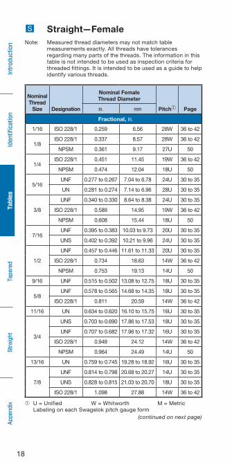
S Straight—FemaleNote: Measured thread diameters may not match table
measurements exactly . All threads have tolerances regarding many parts of the threads . The information in this table is not intended to be used as inspection criteria for threaded fittings . It is intended to be used as a guide to help identify various threads .
➀ U = Unified W = Whitworth M = Metric Labeling on each Swagelok pitch gauge form
(continued on next page)
NominalThread
Size Designation
Nominal FemaleThread Diameter
Pitch➀ Pagein. mm
Fractional, in.
1/16 ISO 228/1 0 .259 6 .56 28W 36 to 42
1/8ISO 228/1 0 .337 8 .57 28W 36 to 42
NPSM 0 .361 9 .17 27U 50
1/4ISO 228/1 0 .451 11 .45 19W 36 to 42
NPSM 0 .474 12 .04 18U 50
5/16UNF 0 .277 to 0 .267 7 .04 to 6 .78 24U 30 to 35
UN 0 .281 to 0 .274 7 .14 to 6 .96 28U 30 to 35
3/8
UNF 0 .340 to 0 .330 8 .64 to 8 .38 24U 30 to 35
ISO 228/1 0 .589 14 .95 19W 36 to 42
NPSM 0 .608 15 .44 18U 50
7/16UNF 0 .395 to 0 .383 10 .03 to 9 .73 20U 30 to 35
UNS 0 .402 to 0 .392 10 .21 to 9 .96 24U 30 to 35
1/2
UNF 0 .457 to 0 .446 11 .61 to 11 .33 20U 30 to 35
ISO 228/1 0 .734 18 .63 14W 36 to 42
NPSM 0 .753 19 .13 14U 50
9/16 UNF 0 .515 to 0 .502 13 .08 to 12 .75 18U 30 to 35
5/8UNF 0 .578 to 0 .565 14 .68 to 14 .35 18U 30 to 35
ISO 228/1 0 .811 20 .59 14W 36 to 42
11/16 UN 0 .634 to 0 .620 16 .10 to 15 .75 16U 30 to 35
3/4
UNS 0 .703 to 0 .690 17 .86 to 17 .53 18U 30 to 35
UNF 0 .707 to 0 .682 17 .96 to 17 .32 16U 30 to 35
ISO 228/1 0 .949 24 .12 14W 36 to 42
NPSM 0 .964 24 .49 14U 50
13/16 UN 0 .759 to 0 .745 19 .28 to 18 .92 16U 30 to 35
7/8
UNF 0 .814 to 0 .798 20 .68 to 20 .27 14U 30 to 35
UNS 0 .828 to 0 .815 21 .03 to 20 .70 18U 30 to 35
ISO 228/1 1 .098 27 .88 14W 36 to 42
19
IdentificationTables
TaperedStraight
IntroductionAppendix
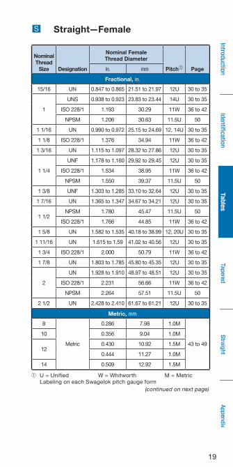
S Straight—Female
➀ U = Unified W = Whitworth M = Metric Labeling on each Swagelok pitch gauge form
(continued on next page)
NominalThread
Size Designation
Nominal FemaleThread Diameter
Pitch➀ Pagein. mm
Fractional, in.
15/16 UN 0 .847 to 0 .865 21 .51 to 21 .97 12U 30 to 35
1
UNS 0 .938 to 0 .923 23 .83 to 23 .44 14U 30 to 35
ISO 228/1 1 .193 30 .29 11W 36 to 42
NPSM 1 .206 30 .63 11 .5U 50
1 1/16 UN 0 .990 to 0 .972 25 .15 to 24 .69 12, 14U 30 to 35
1 1/8 ISO 228/1 1 .376 34 .94 11W 36 to 42
1 3/16 UN 1 .115 to 1 .097 28 .32 to 27 .86 12U 30 to 35
1 1/4
UNF 1 .178 to 1 .160 29 .92 to 29 .45 12U 30 to 35
ISO 228/1 1 .534 38 .95 11W 36 to 42
NPSM 1 .550 39 .37 11 .5U 50
1 3/8 UNF 1 .303 to 1 .285 33 .10 to 32 .64 12U 30 to 35
1 7/16 UN 1 .365 to 1 .347 34 .67 to 34 .21 12U 30 to 35
1 1/2NPSM 1 .780 45 .47 11 .5U 50
ISO 228/1 1 .766 44 .85 11W 36 to 42
1 5/8 UN 1 .582 to 1 .535 40 .18 to 38 .99 12, 20U 30 to 35
1 11/16 UN 1 .615 to 1 .59 41 .02 to 40 .56 12U 30 to 35
1 3/4 ISO 228/1 2 .000 50 .79 11W 36 to 42
1 7/8 UN 1 .803 to 1 .785 45 .80 to 45 .35 12U 30 to 35
2
UN 1 .928 to 1 .910 48 .97 to 48 .51 12U 30 to 35
ISO 228/1 2 .231 56 .66 11W 36 to 42
NPSM 2 .264 57 .51 11 .5U 50
2 1/2 UN 2 .428 to 2 .410 61 .67 to 61 .21 12U 30 to 35
Metric, mm
8
Metric
0 .286 7 .98 1 .0M
43 to 49
10 0 .356 9 .04 1 .0M
120 .430 10 .92 1 .5M
0 .444 11 .27 1 .0M
14 0 .509 12 .92 1 .5M
20
Iden
tifica
tion
Tables
Tape
red
Straight
Intro
duction
Appe
ndix
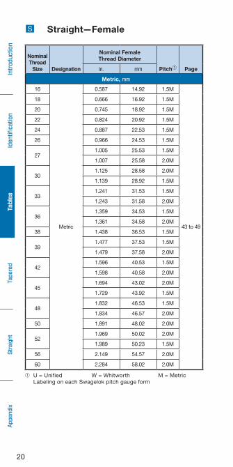
S Straight—Female
NominalThread
Size Designation
Nominal FemaleThread Diameter
Pitch➀ Pagein. mm
Metric, mm
16
Metric
0 .587 14 .92 1 .5M
43 to 49
18 0 .666 16 .92 1 .5M
20 0 .745 18 .92 1 .5M
22 0 .824 20 .92 1 .5M
24 0 .887 22 .53 1 .5M
26 0 .966 24 .53 1 .5M
271 .005 25 .53 1 .5M
1 .007 25 .58 2 .0M
301 .125 28 .58 2 .0M
1 .139 28 .92 1 .5M
331 .241 31 .53 1 .5M
1 .243 31 .58 2 .0M
361 .359 34 .53 1 .5M
1 .361 34 .58 2 .0M
38 1 .438 36 .53 1 .5M
391 .477 37 .53 1 .5M
1 .479 37 .58 2 .0M
421 .596 40 .53 1 .5M
1 .598 40 .58 2 .0M
451 .694 43 .02 2 .0M
1 .729 43 .92 1 .5M
481 .832 46 .53 1 .5M
1 .834 46 .57 2 .0M
50 1 .891 48 .02 2 .0M
521 .969 50 .02 2 .0M
1 .989 50 .23 1 .5M
56 2 .149 54 .57 2 .0M
60 2 .284 58 .02 2 .0M
➀ U = Unified W = Whitworth M = Metric Labeling on each Swagelok pitch gauge form
21
IdentificationTables
TaperedStraight
IntroductionAppendix
The following characteristics and information should be considered when using tapered threads:■The seal is designed to take place between the
tapered threads .■Tapered pipe threads always need a sealant to
seal system fluids and reduce the potential for galling of the threads .
■Products such as Swagelok PTFE tape, SWAK®, anaerobic pipe thread sealant with PTFE, and PTFE Free pipe thread sealant perform both the lubricating and sealing functions . If the two pieces of metal are forced against each other without lubrication, galling is possible .
■After following the sealant and lubricant application instructions, the amount of tightening is discretionary . There is no standard for torque or number of turns .
Tapered Threads

22
Iden
tifica
tion
Tables
Tape
red
Straight
Intro
duction
Appe
ndix
NPT(also known as ASME B1 .20 .1)
Characteristics■ Tapered thread (1° 47')■ Truncation of roots
and crests are flat■ 60° thread angle■ Pitch is measured in
threads per inch
ISO 7/1(also known as EN 10226-1 and JIS B0203)
Characteristics■ Tapered thread (1° 47')■ Truncation of roots and
crests are rounded■ 55° thread angle■ Pitch is measured in
threads per inch
60°
1° 47'
CA-ELD-232CAJON THREAD ID
55°
1° 47'
Tapered Threads
23
IdentificationTables
TaperedStraight
IntroductionAppendix
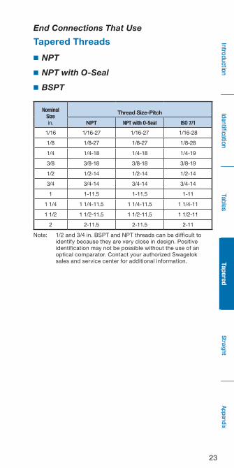
End Connections That Use
Tapered Threads
■ NPT
■ NPT with O-Seal
■ BSPT
Note: 1/2 and 3/4 in . BSPT and NPT threads can be difficult to identify because they are very close in design . Positive identification may not be possible without the use of an optical comparator . Contact your authorized Swagelok sales and service center for additional information .
NominalSizein .
Thread Size-Pitch
NPT NPT with O-Seal ISO 7/1
1/16 1/16-27 1/16-27 1/16-28
1/8 1/8-27 1/8-27 1/8-28
1/4 1/4-18 1/4-18 1/4-19
3/8 3/8-18 3/8-18 3/8-19
1/2 1/2-14 1/2-14 1/2-14
3/4 3/4-14 3/4-14 3/4-14
1 1-11 .5 1-11 .5 1-11
1 1/4 1 1/4-11 .5 1 1/4-11 .5 1 1/4-11
1 1/2 1 1/2-11 .5 1 1/2-11 .5 1 1/2-11
2 2-11 .5 2-11 .5 2-11
24
Iden
tifica
tion
Tables
Tape
red
Straight
Intro
duction
Appe
ndix
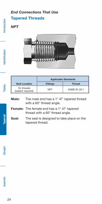
Male: The male end has a 1° 47' tapered thread with a 60° thread angle .
Female: The female end has a 1° 47' tapered thread with a 60° thread angle .
Seal: The seal is designed to take place on the tapered thread .
Seal Location
Applicable Standards
Fittings Thread
On threads(sealant required)
NPT ASME B1 .20 .1
End Connections That Use
Tapered Threads
NPT

25
IdentificationTables
TaperedStraight
IntroductionAppendix
NPT with O-Seal
Male: The male end has an undersized NPT thread and an O-ring groove on the shoulder of the hex .
Female: The female end has an NPT thread and a smooth, flat surface .
Seal: The seal takes place by compressing the O-ring against the face of the female component .
O-ring
Seal Location
Applicable Standards
Fittings Thread
O-ring compression None ASME B1 .20 .1
End Connections That Use
Tapered Threads

26
Iden
tifica
tion
Tables
Tape
red
Straight
Intro
duction
Appe
ndix
BSPT
JIS R and JIS Rc
DIN 3852 Part 2, Type C
Male: The male end has a 1° 47' tapered thread with a 55° thread angle .
Female: The female end has a 1° 47' tapered thread with a 55° thread angle .
Seal: The seal is designed to take place on the tapered thread .
Seal Location
Applicable Standards
Fittings Thread
On threads(sealant required)
JIS B8363BS 5200
DIN 3852 Part 2ISO 7/1
End Connections That Use
Tapered Threads

27
IdentificationTables
TaperedStraight
IntroductionAppendix
Worldwide, there are many end connections available with straight threads . Each end connection, however, will generally have threads that are one of the three most common: ASME B1 .1 (unified screw thread), ISO 228/1, or ISO 261 straight threads .
Because the threads of the mating fittings are parallel to each other, there is no interference between the flanks, crests, and roots . Consequently, the seal must be made with a gasket, O-ring, or some metal to metal contact . A sealant is not required or recommended on straight threads . Depending on the application and materials, thread lubricant may be used .
Unified Screw Thread(also known as ASME B1 .1)
Characteristics■ Straight thread■ Truncation of roots
and crests are flat■ 60° flank angle■ Diameter and pitch
measured in inches
Thread Series■ UN: Male and female screw thread■ UNR: Male screw thread only (more rounded crest)■ UNC/UNRC: Coarse thread series■ UNF/UNRF: Fine thread series■ UNEF/UNREF: Extra-fine thread series■ UNS/UNRS: Selected special combinations of
diameters, pitches, and lengths of engagement .
60°
Straight Threads

28
Iden
tifica
tion
Tables
Tape
red
Straight
Intro
duction
Appe
ndix
ISO 228/1(also known as BSPP, JIS B0202)
Characteristics■ Straight thread■ Truncation of roots and
crests are rounded■ 55° flank angle■ Threads are measured
in inches
Metric(also known as ISO 261, JIS B0205, ASME B1 .13M)
Characteristics■ Straight thread■ Truncation of roots
and crests are flat■ 60° flank angle■ Threads are measured
in millimeters
NPSM (also known as ASME B1 .20 .1)
Characteristics■ Straight thread■ Truncation of roots
and crests are flat■ 60° flank angle■ Threads are measured
in inches
60°
60°
55°
Straight Threads
29
IdentificationTables
TaperedStraight
IntroductionAppendix
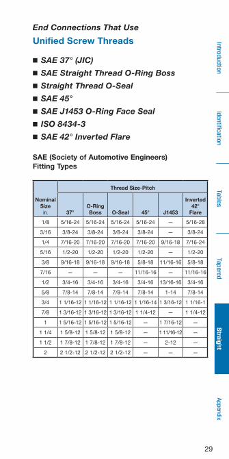
■ SAE 37° (JIC)
■ SAE Straight Thread O-Ring Boss
■ Straight Thread O-Seal
■ SAE 45°
■ SAE J1453 O-Ring Face Seal
■ ISO 8434-3
■ SAE 42° Inverted Flare
SAE (Society of Automotive Engineers) Fitting Types
NominalSize
in.
Thread Size-Pitch
37°O-RingBoss O-Seal 45° J1453
Inverted42°
Flare
1/8 5/16-24 5/16-24 5/16-24 5/16-24 — 5/16-28
3/16 3/8-24 3/8-24 3/8-24 3/8-24 — 3/8-24
1/4 7/16-20 7/16-20 7/16-20 7/16-20 9/16-18 7/16-24
5/16 1/2-20 1/2-20 1/2-20 1/2-20 — 1/2-20
3/8 9/16-18 9/16-18 9/16-18 5/8-18 11/16-16 5/8-18
7/16 — — — 11/16-16 — 11/16-16
1/2 3/4-16 3/4-16 3/4-16 3/4-16 13/16-16 3/4-16
5/8 7/8-14 7/8-14 7/8-14 7/8-14 1-14 7/8-14
3/4 1 1/16-12 1 1/16-12 1 1/16-12 1 1/16-14 1 3/16-12 1 1/16-1
7/8 1 3/16-12 1 3/16-12 1 3/16-12 1 1/4-12 — 1 1/4-12
1 1 5/16-12 1 5/16-12 1 5/16-12 — 1 7/16-12 —
1 1/4 1 5/8-12 1 5/8-12 1 5/8-12 — 1 11/16-12 —
1 1/2 1 7/8-12 1 7/8-12 1 7/8-12 — 2-12 —
2 2 1/2-12 2 1/2-12 2 1/2-12 — — —
End Connections That Use
Unified Screw Threads

30
Iden
tifica
tion
Tables
Tape
red
Straight
Intro
duction
Appe
ndix
SAE 37° (JIC)
Male: The male end has a straight thread and a 37° cone taper .
Female: The female end has a straight thread and a nut captured on tubing with a mating 37° flare or a 37° tapered gland .
Seal: The seal takes place between the male taper and the inside diameter of the tapered gland or flared tubing .
Gland
Tubing Sleeve
Seal Location
Applicable Standards
Fittings Thread
Mating 37°flared surfaces
SAE J514 ASME B1 .1
End Connections That Use
Unified Screw Threads

31
IdentificationTables
TaperedStraight
IntroductionAppendix
SAE Straight Thread O-Ring Boss
Male: The male end has a straight thread and an O-ring .
Female: The female end has a straight thread and a taper to accept the O-ring .
Seal: The seal takes place by compressing the O-ring into the taper .
O-ring
Seal Location
Applicable Standards
Fittings Thread
O-ring compression SAE J1926, ISO 11926 ASME B1 .1
End Connections That Use
Unified Screw Threads

32
Iden
tifica
tion
Tables
Tape
red
Straight
Intro
duction
Appe
ndix
Straight Thread O-Seal
Male: The male end has a straight thread and an O-ring groove on the shoulder of the hex .
Female: The female end has a straight thread and a smooth, flat surface .
Seal: The seal takes place by compressing the O-ring against the face of the female component .
O-ring
Seal Location
Applicable Standards
Fittings Thread
O-ring compression None ASME B1 .1
End Connections That Use
Unified Screw Threads

33
IdentificationTables
TaperedStraight
IntroductionAppendix
SAE 45°
Male: The male end has a straight thread and a 45° cone taper .
Female: The female end has a straight thread and a nut captured on tubing with a mating 45° flare or a 45° tapered gland .
Seal: The seal takes place between the male taper and the inside diameter of the tapered gland or flared tubing .
Gland
Tubing Sleeve
Seal Location
Applicable Standards
Fittings Thread
Mating 45°flared surface
SAE J512SAE J513
ASME B1 .1
End Connections That Use
Unified Screw Threads
34
Iden
tifica
tion
Tables
Tape
red
Straight
Intro
duction
Appe
ndix
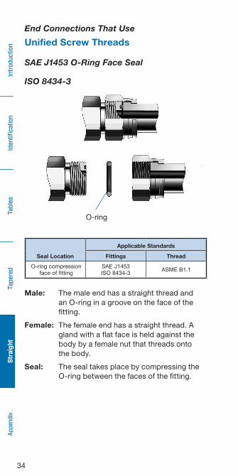
SAE J1453 O-Ring Face Seal
ISO 8434-3
Male: The male end has a straight thread and an O-ring in a groove on the face of the fitting .
Female: The female end has a straight thread . A gland with a flat face is held against the body by a female nut that threads onto the body .
Seal: The seal takes place by compressing the O-ring between the faces of the fitting .
O-ring
Seal Location
Applicable Standards
Fittings Thread
O-ring compressionface of fitting
SAE J1453ISO 8434-3
ASME B1 .1
End Connections That Use
Unified Screw Threads
35
IdentificationTables
TaperedStraight
IntroductionAppendix
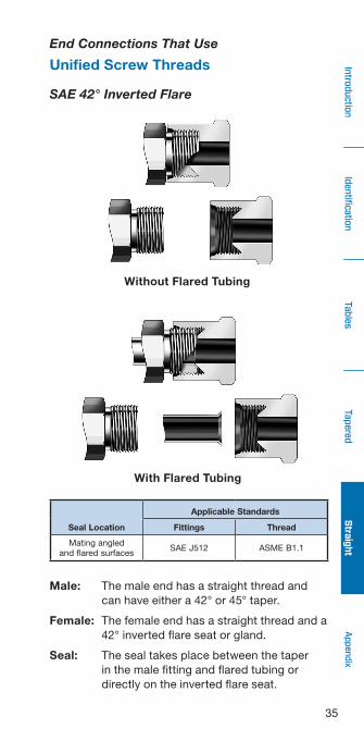
SAE 42° Inverted Flare
Male: The male end has a straight thread and can have either a 42° or 45° taper .
Female: The female end has a straight thread and a 42° inverted flare seat or gland .
Seal: The seal takes place between the taper in the male fitting and flared tubing or directly on the inverted flare seat .
Without Flared Tubing
With Flared Tubing
Seal Location
Applicable Standards
Fittings Thread
Mating angledand flared surfaces
SAE J512 ASME B1 .1
End Connections That Use
Unified Screw Threads
36
Iden
tifica
tion
Tables
Tape
red
Straight
Intro
duction
Appe
ndix
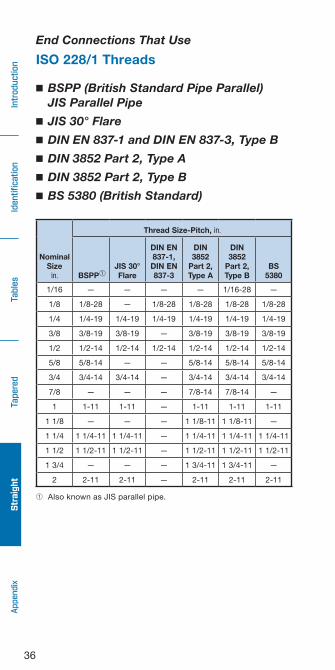
■ BSPP (British Standard Pipe Parallel) JIS Parallel Pipe
■ JIS 30° Flare
■ DIN EN 837-1 and DIN EN 837-3, Type B
■ DIN 3852 Part 2, Type A
■ DIN 3852 Part 2, Type B
■ BS 5380 (British Standard)
➀ Also known as JIS parallel pipe .
NominalSize
in.
Thread Size-Pitch, in.
BSPP➀JIS 30°Flare
DIN EN 837-1,
DIN EN 837-3
DIN 3852
Part 2,Type A
DIN 3852
Part 2,Type B
BS 5380
1/16 — — — — 1/16-28 —
1/8 1/8-28 — 1/8-28 1/8-28 1/8-28 1/8-28
1/4 1/4-19 1/4-19 1/4-19 1/4-19 1/4-19 1/4-19
3/8 3/8-19 3/8-19 — 3/8-19 3/8-19 3/8-19
1/2 1/2-14 1/2-14 1/2-14 1/2-14 1/2-14 1/2-14
5/8 5/8-14 — — 5/8-14 5/8-14 5/8-14
3/4 3/4-14 3/4-14 — 3/4-14 3/4-14 3/4-14
7/8 — — — 7/8-14 7/8-14 —
1 1-11 1-11 — 1-11 1-11 1-11
1 1/8 — — — 1 1/8-11 1 1/8-11 —
1 1/4 1 1/4-11 1 1/4-11 — 1 1/4-11 1 1/4-11 1 1/4-11
1 1/2 1 1/2-11 1 1/2-11 — 1 1/2-11 1 1/2-11 1 1/2-11
1 3/4 — — — 1 3/4-11 1 3/4-11 —
2 2-11 2-11 — 2-11 2-11 2-11
End Connections That Use
ISO 228/1 Threads

37
IdentificationTables
TaperedStraight
IntroductionAppendix
BSPP (British Standard Pipe Parallel)
JIS Parallel Pipe
BSPP and JIS parallel pipe fittings are identical in design, appearance, and dimensions .
Seal Location
Applicable Standards
Fittings Thread
Mating 30° angled Surfaces or O-ring
Compression
BS 5200JIS B8363
ISO 228/1
End Connections That Use
ISO 228/1 Threads
Male: The male end has a straight thread and a 30° taper .
Female: The female end is a nut with a straight thread captured on a 30° cone tapered gland .
Seal: The seal takes place between the taper in the male fitting and the 30° cone tapered gland .

38
Iden
tifica
tion
Tables
Tape
red
Straight
Intro
duction
Appe
ndix
JIS 30° Flare
Male: The male end has a straight thread and a 30° cone taper .
Female: The female end has a straight thread and a nut captured on tubing with a mating 30° flare or a 30° tapered gland .
Seal: The seal takes place between the male taper and the ID of the tapered gland or flared tubing .
Seal Location
Applicable Standards
Fittings Thread
Mating 30° angledor flared surfaces
JIS B8363 ISO 228/1
End Connections That Use
ISO 228/1 Threads
Gland
Tubing Sleeve

39
IdentificationTables
TaperedStraight
IntroductionAppendix
Gasket
Female➀
DIN EN 837-1 and DIN EN 837-3, Type B
JIS B0202
Male: The male fitting has a straight thread and a spigot which fits through the inside diameter of the gasket .
➀Female: The female has a straight thread and a counterbore in the inside diameter of the fitting to accept a gasket .
➁Female: The female has a straight thread and a counterbore in the inside diameter of the fitting to accept a gasket . The counterbore is larger to help ensure the male end compresses the gasket into a sealing position .
Seal: The seal takes place by compressing a gasket between the male and female fittings .
CounterboreFemale➁
Gasket
Seal Location
Applicable Standards
Fittings Thread
Gasket compression DIN EN 837-1, 837-3 ISO 228/1, JIS B0202
End Connections That Use
ISO 228/1 Threads
40
Iden
tifica
tion
Tables
Tape
red
Straight
Intro
duction
Appe
ndix
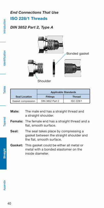
DIN 3852 Part 2, Type A
Male: The male end has a straight thread and a straight shoulder .
Female: The female end has a straight thread and a flat, smooth surface .
Seal: The seal takes place by compressing a gasket between the straight shoulder and the flat, smooth surface .
Gasket: This gasket could be either all metal or metal with a bonded elastomer on the inside diameter .
Shoulder
Bonded gasket
Seal Location
Applicable Standards
Fittings Thread
Gasket compression DIN 3852 Part 2 ISO 228/1
End Connections That Use
ISO 228/1 Threads
41
IdentificationTables
TaperedStraight
IntroductionAppendix
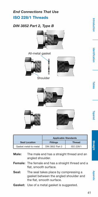
DIN 3852 Part 2, Type B
Male: The male end has a straight thread and an angled shoulder .
Female: The female end has a straight thread and a flat, smooth surface .
Seal: The seal takes place by compressing a gasket between the angled shoulder and the flat, smooth surface .
Gasket: Use of a metal gasket is suggested .
All-metal gasket
Shoulder
Seal Location
Applicable Standards
Fittings Thread
Gasket metal-to-metal DIN 3852 Part 2 ISO 228/1
End Connections That Use
ISO 228/1 Threads
42
Iden
tifica
tion
Tables
Tape
red
Straight
Intro
duction
Appe
ndix
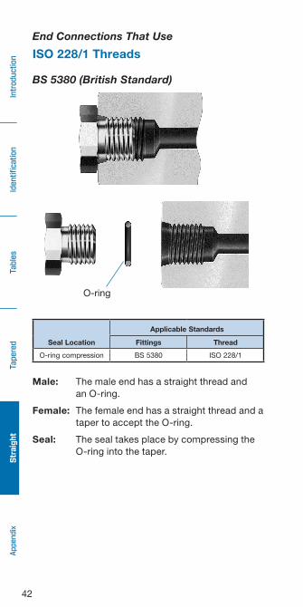
BS 5380 (British Standard)
Male: The male end has a straight thread and an O-ring .
Female: The female end has a straight thread and a taper to accept the O-ring .
Seal: The seal takes place by compressing the O-ring into the taper .
Seal Location
Applicable Standards
Fittings Thread
O-ring compression BS 5380 ISO 228/1
End Connections That Use
ISO 228/1 Threads
O-ring

43
IdentificationTables
TaperedStraight
IntroductionAppendix
■ DIN 7631■ JIS Parallel Pipe Metric■ DIN EN 837-1 and DIN EN 837-3, Type B■ DIN 3852 Part 1, Type A■ DIN 3852 Part 1, Type B■ ISO 6149-1, ISO 6149-2, and ISO 6149-3
NominalSizemm
Thread Size-Pitch
DIN 7631
JIS Parallel
Pipe Metric
DIN EN 837-1,
DIN EN 837-3
DIN 3852
Part 1Type A
DIN 3852
Part 1Type B
ISO 6149-1, 6149-2, 6149-3
M8 — — — M8 × 1 M8 × 1 M8 × 1
M10 M10 × 1 — M10 × 1 M10 × 1 M10 × 1 M10 × 1
M12 M12 × 1 .5 — M12 × 1 .5 M12 × 1 .5 M12 × 1 .5 M12 × 1 .5
M14 M14 × 1 .5 M14 × 1 .5 — M14 × 1 .5 M14 × 1 .5 M14× 1 .5
M16 M16 × 1 .5 — — M16 × 1 .5 M16 × 1 .5 M16 × 1 .5
M18 M18 × 1 .5 M18 × 1 .5 — M18 × 1 .5 M18 × 1 .5 M18 × 1 .5
M20 — — M20 × 1 .5 M20 × 1 .5 M20 × 1 .5 M20 × 1 .5
M22 M22 × 1 .5 M22 × 1 .5 — M22 × 1 .5 M22 × 1 .5 M22 × 1 .5
M24 — — — M24 × 1 .5 M24 × 1 .5 —
M26 M26 × 1 .5 — — M26 × 1 .5 M26 × 1 .5 M26 × 1 .5
M27 — M27 × 2 .0 — M27 × 2 .0 M27 × 2 .0 M27 × 2 .0
M30M30 × 1 .5 — — M30 × 1 .5 M30 × 1 .5 —
— — — M30 × 2 .0 M30 × 2 .0 —
M33 — M33 × 2 .0 — M30 × 2 .0 M30 × 2 .0 M30 × 2 .0
M36— — — M36 × 1 .5 M36 × 1 .5 —
— — — M36 × 2 .0 M36 × 2 .0 —
M38 M38 × 1 .5 — — M38 × 1 .5 M38 × 1 .5 —
M39 — — — M39 × 1 .5 M39 × 1 .5 —
M42— M42 × 1 .5 — M42 × 2 .0 M42 × 2 .0 M42 × 2 .0
— — — M42 × 2 .0 M42 × 2 .0 —
M45M45 × 2 .0 — — M45 × 1 .5 M45 × 1 .5 —
— — — M45 × 2 .0 M45 × 2 .0 —
M48— — — M48 × 1 .5 M48 × 1 .5 M48 × 2 .0
— — — M48 × 2 .0 M48 × 2 .0 —
M50 — M50 × 2 .0 — — — M50 × 2 .0
M52M52 × 1 .5 — — M52 × 1 .5 M52 × 1 .5 —
— — — M52 × 2 .0 M52 × 2 .0 —
M56 — — — M56 × 2 .0 M56 × 2 .0 —
M60 — M60 × 2 .0 — M60 × 2 .0 M60 × 2 .0 M60 × 2 .0
End Connections That Use
Metric (ISO 261) Threads
44
Iden
tifica
tion
Tables
Tape
red
Straight
Intro
duction
Appe
ndix
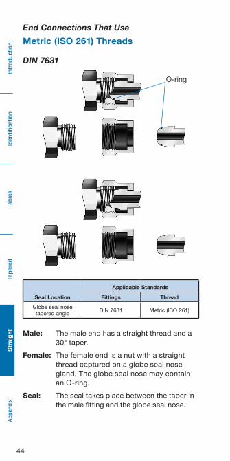
DIN 7631
Male: The male end has a straight thread and a 30° taper .
Female: The female end is a nut with a straight thread captured on a globe seal nose gland . The globe seal nose may contain an O-ring .
Seal: The seal takes place between the taper in the male fitting and the globe seal nose .
O-ring
Seal Location
Applicable Standards
Fittings Thread
Globe seal nosetapered angle
DIN 7631 Metric (ISO 261)
End Connections That Use
Metric (ISO 261) Threads
O-ring
45
IdentificationTables
TaperedStraight
IntroductionAppendix
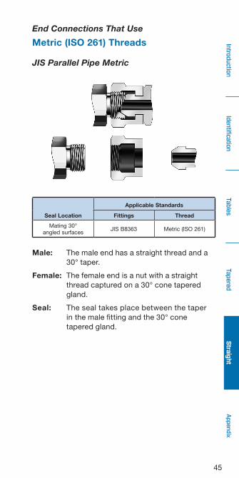
JIS Parallel Pipe Metric
Male: The male end has a straight thread and a 30° taper .
Female: The female end is a nut with a straight thread captured on a 30° cone tapered gland .
Seal: The seal takes place between the taper in the male fitting and the 30° cone tapered gland .
Seal Location
Applicable Standards
Fittings Thread
Mating 30°angled surfaces
JIS B8363 Metric (ISO 261)
End Connections That Use
Metric (ISO 261) Threads
46
Iden
tifica
tion
Tables
Tape
red
Straight
Intro
duction
Appe
ndix
Gasket
Female➀
CounterboreFemale➁
Gasket
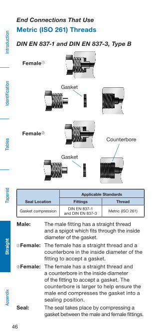
DIN EN 837-1 and DIN EN 837-3, Type B
Seal Location
Applicable Standards
Fittings Thread
Gasket compressionDIN EN 837-1
and DIN EN 837-3Metric (ISO 261)
Male: The male fitting has a straight thread and a spigot which fits through the inside diameter of the gasket .
➀Female: The female has a straight thread and a counterbore in the inside diameter of the fitting to accept a gasket .
➁Female: The female has a straight thread and a counterbore in the inside diameter of the fitting to accept a gasket . The counterbore is larger to help ensure the male end compresses the gasket into a sealing position .
Seal: The seal takes place by compressing a gasket between the male and female fittings .
End Connections That Use
Metric (ISO 261) Threads
47
IdentificationTables
TaperedStraight
IntroductionAppendix
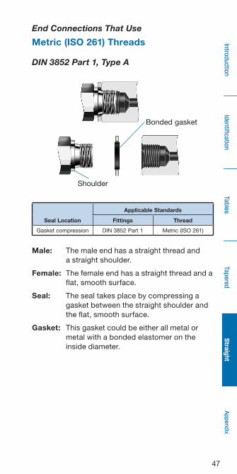
DIN 3852 Part 1, Type A
Male: The male end has a straight thread and a straight shoulder .
Female: The female end has a straight thread and a flat, smooth surface .
Seal: The seal takes place by compressing a gasket between the straight shoulder and the flat, smooth surface .
Gasket: This gasket could be either all metal or metal with a bonded elastomer on the inside diameter .
Shoulder
Bonded gasket
Seal Location
Applicable Standards
Fittings Thread
Gasket compression DIN 3852 Part 1 Metric (ISO 261)
End Connections That Use
Metric (ISO 261) Threads
48
Iden
tifica
tion
Tables
Tape
red
Straight
Intro
duction
Appe
ndix
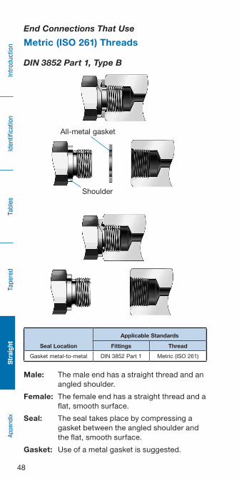
DIN 3852 Part 1, Type B
Male: The male end has a straight thread and an angled shoulder .
Female: The female end has a straight thread and a flat, smooth surface .
Seal: The seal takes place by compressing a gasket between the angled shoulder and the flat, smooth surface .
Gasket: Use of a metal gasket is suggested .
All-metal gasket
Shoulder
Seal Location
Applicable Standards
Fittings Thread
Gasket metal-to-metal DIN 3852 Part 1 Metric (ISO 261)
End Connections That Use
Metric (ISO 261) Threads
49
IdentificationTables
TaperedStraight
IntroductionAppendix
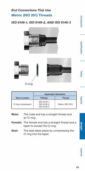
ISO 6149-1, ISO 6149-2, AND ISO 6149-3
Male: The male end has a straight thread and an O-ring .
Female: The female end has a straight thread and a taper to accept the O-ring .
Seal: The seal takes place by compressing the O-ring into the taper .
O-ring
Seal Location
Applicable Standards
Fittings Thread
O-ring compression ISO 6149-1, ISO 6149-2, ISO 6149-3
Metric (ISO 261)
End Connections That Use
Metric (ISO 261) Threads
50
Iden
tifica
tion
Tables
Tape
red
Straight
Intro
duction
Appe
ndix
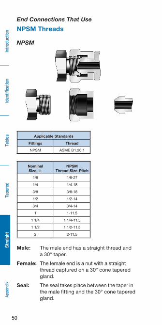
NPSM
Male: The male end has a straight thread and a 30° taper .
Female: The female end is a nut with a straight thread captured on a 30° cone tapered gland .
Seal: The seal takes place between the taper in the male fitting and the 30° cone tapered gland .
Applicable Standards
Fittings Thread
NPSM ASME B1 .20 .1
NominalSize, in.
NPSMThread SIze-Pitch
1/8 1/8-27
1/4 1/4-18
3/8 3/8-18
1/2 1/2-14
3/4 3/4-14
1 1-11 .5
1 1/4 1 1/4-11 .5
1 1/2 1 1/2-11 .5
2 2-11 .5
End Connections That Use
NPSM Threads

51
IdentificationTables
TaperedStraight
IntroductionAppendix
End Connection to Thread Matrix
End Connection Page Thread Standard Page
BSP (British Pipe Standard)
BSPP (5200) 37 ISO 228/1 28
BS 5380 42 ISO 228/1 28
DIN (Deutsches Institut für Normung e.V.)
DIN EN 837-1 andDIN EN 837-3, Type B
39 ISO 228/1 28
DIN EN 837-1 andDIN EN 837-3, Type B
46 Metric (ISO 261) 28
DIN 3852 Part 1, Type A 47 Metric (ISO 261)
28DIN 3852 Part 1, Type B 48 Metric (ISO 261)
DIN 3852 Part 2, Type A 40 ISO 228/1
DIN 3852 Part 2, Type B 41 ISO 228/1
DIN 3852 Part 2, Type C 26 ISO 7/1 22
ISO 6149-1, ISO 6149-2,and ISO 6149-3
49 Metric (ISO 261)28
DIN 7631 44 Metric (ISO 261)
JIS (Japanese Industrial Standard)
JIS 30° Flare (B8363) 38 ISO 228/1
28JIS (B8363) 37 ISO 228/1
JIS (B8363) 45 Metric (ISO 261)
JIS (B8363) 26 ISO 7/1
NPSM (National Pipe Straight Mechanical)
NPSM 50 ASME B1 .20 .1 28
NPT (National Pipe Taper)
NPT 24 ASME B1 .20 .1 22
SAE (Society of Automotive Engineers)
SAE J1453 O-Ring Face Seal 34
ASME B1 .1 27
SAE 37° (JIC) (J514) 30
SAE 42° Inverted Flare (J512) 35
SAE 45° (J512, J513) 33
SAE Straight ThreadO-Ring Boss (J1926)
31
52
Iden
tifica
tion
Tables
Tape
red
Straight
Intro
duction
Appe
ndix
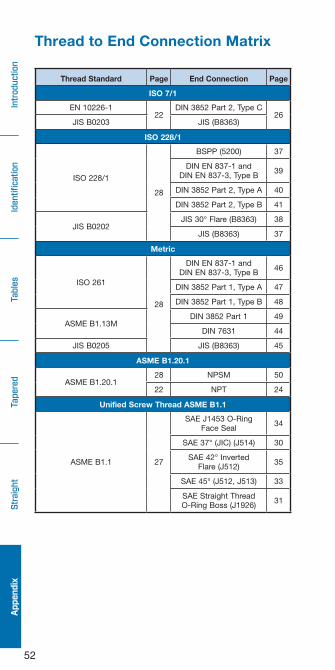
Thread Standard Page End Connection Page
ISO 7/1
EN 10226-122
DIN 3852 Part 2, Type C26
JIS B0203 JIS (B8363)
ISO 228/1
ISO 228/1
28
BSPP (5200) 37
DIN EN 837-1 andDIN EN 837-3, Type B
39
DIN 3852 Part 2, Type A 40
DIN 3852 Part 2, Type B 41
JIS B0202JIS 30° Flare (B8363) 38
JIS (B8363) 37
Metric
ISO 261
28
DIN EN 837-1 and DIN EN 837-3, Type B
46
DIN 3852 Part 1, Type A 47
DIN 3852 Part 1, Type B 48
ASME B1 .13MDIN 3852 Part 1 49
DIN 7631 44
JIS B0205 JIS (B8363) 45
ASME B1.20.1
ASME B1 .20 .128 NPSM 50
22 NPT 24
Unified Screw Thread ASME B1.1
ASME B1 .1 27
SAE J1453 O-RingFace Seal
34
SAE 37° (JIC) (J514) 30
SAE 42° InvertedFlare (J512)
35
SAE 45° (J512, J513) 33
SAE Straight ThreadO-Ring Boss (J1926)
31
Thread to End Connection Matrix

53
IdentificationTables
TaperedStraight
IntroductionAppendix
Thread Identification Tools
CaliperA caliper is used to determine the thread diameter . (Calibration of calipers is the responsibility of the end user .)
Combination Seat and Pitch GaugeSeat and pitch gauges are conveniently combined into one tool .
The seat gauge is used to determine end connection seat angles of 45°, 37°, and 30° .
The pitch gauge is used to identify the thread pitch . Note that a pitch gauge may be Unified (threads per inch), Whitworth (threads per inch), or metric (millimeters per thread) as marked on the back of each gauge form .
Thread pitch gauges
Seat angle gauges
54
Iden
tifica
tion
Tables
Tape
red
Straight
Intro
duction
Appe
ndix
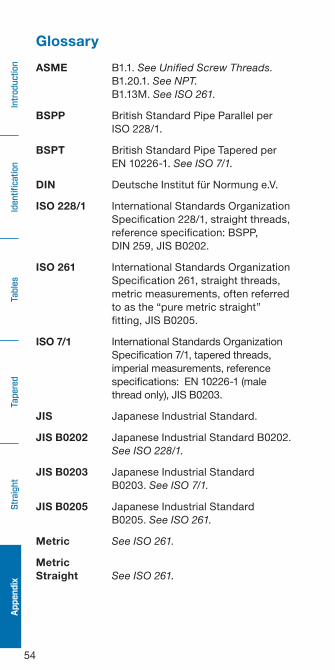
Glossary
ASME B1 .1 . See Unified Screw Threads. B1 .20 .1 . See NPT. B1 .13M . See ISO 261.
BSPP British Standard Pipe Parallel per ISO 228/1 .
BSPT British Standard Pipe Tapered per EN 10226-1 . See ISO 7/1.
DIN Deutsche Institut für Normung e .V .
ISO 228/1 International Standards Organization Specification 228/1, straight threads, reference specification: BSPP, DIN 259, JIS B0202 .
ISO 261 International Standards Organization Specification 261, straight threads, metric measurements, often referred to as the “pure metric straight” fitting, JIS B0205 .
ISO 7/1 International Standards Organization Specification 7/1, tapered threads, imperial measurements, reference specifications: EN 10226-1 (male thread only), JIS B0203 .
JIS Japanese Industrial Standard .
JIS B0202 Japanese Industrial Standard B0202 . See ISO 228/1.
JIS B0203 Japanese Industrial Standard B0203 . See ISO 7/1.
JIS B0205 Japanese Industrial Standard B0205 . See ISO 261.
Metric See ISO 261.
Metric Straight See ISO 261.
55
IdentificationTables
TaperedStraight
IntroductionAppendix
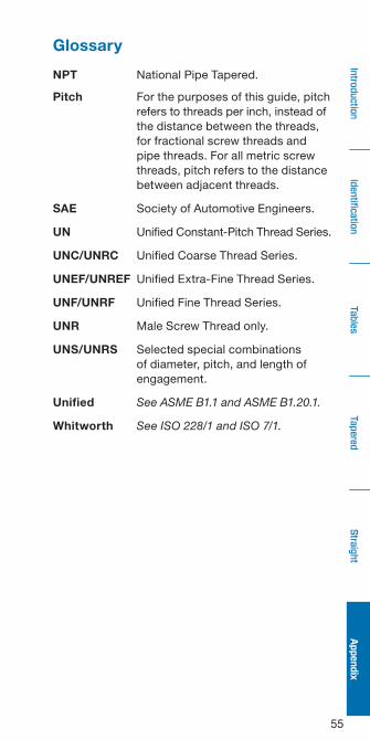
Glossary
NPT National Pipe Tapered .
Pitch For the purposes of this guide, pitch refers to threads per inch, instead of the distance between the threads, for fractional screw threads and pipe threads . For all metric screw threads, pitch refers to the distance between adjacent threads .
SAE Society of Automotive Engineers .
UN Unified Constant-Pitch Thread Series .
UNC/UNRC Unified Coarse Thread Series .
UNEF/UNREF Unified Extra-Fine Thread Series .
UNF/UNRF Unified Fine Thread Series .
UNR Male Screw Thread only .
UNS/UNRS Selected special combinations of diameter, pitch, and length of engagement .
Unified See ASME B1.1 and ASME B1.20.1.
Whitworth See ISO 228/1 and ISO 7/1.
56
Iden
tifica
tion
Tables
Tape
red
Straight
Intro
duction
Appe
ndix
Warranty InformationSwagelok products are backed by The Swagelok Limited Lifetime Warranty . For a copy, visit swagelok .com or contact your authorized Swagelok representative .
• WARNING Do not mix/interchange Swagelok products or components not governed by industrial design standards, including Swagelok tube fitting end connections, with those of other manufacturers.
Safe Product SelectionWhen selecting a product, the total system design must be considered to ensure safe, trouble-free performance. Function, material compatibility, adequate ratings, proper installation, operation, and maintenance are the responsibilities of the system designer and user. The complete catalog contents must be reviewed to ensure that the system designer and user make a safe product selection.

57

Swagelok, SWAK —TM Swagelok Company © 2015–2021 Swagelok CompanyPrinted in U .S .A ., AGSAugust 2021, RevGMS-13-77