· the wifi library.....190 wifi.begin.....190
TRANSCRIPT

Page 1
Table of Contents
Introduction................................................................................................................................19Overview....................................................................................................................................21
The ESP8266........................................................................................................................22Maturity.................................................................................................................................23The specification...................................................................................................................23ESP8266 Modules.................................................................................................................24
ESP-12.............................................................................................................................24ESP-1...............................................................................................................................28Adafruit HUZZAH..............................................................................................................34NodeMCU devKit..............................................................................................................34node.IT (aka ESP-210).....................................................................................................36SparkFun WiFi Shield – ESP8266....................................................................................36Oak by digistump..............................................................................................................36
Connecting to the ESP8266.......................................................................................................36WiFi Theory...............................................................................................................................38AT Command Programming.......................................................................................................39
Commands............................................................................................................................40Installing the latest AT command processor..........................................................................47
Assembling circuits....................................................................................................................47USB to UART converters.......................................................................................................47Breadboards..........................................................................................................................49Power....................................................................................................................................49Multi-meter / Logic probe / Logic Analyzer.............................................................................50Sundry components..............................................................................................................50Physical construction.............................................................................................................50Recommended setup for programming ESP8266.................................................................51Configuration for flashing the device.....................................................................................53
Programming.............................................................................................................................54Boot mode.............................................................................................................................54The ESP8266 SDK................................................................................................................55
Include directories.............................................................................................................55Compiling..............................................................................................................................56
Loading a program into the ESP8266...............................................................................63Programming environments..............................................................................................67Compilation tools..............................................................................................................67
ar..................................................................................................................................67esptool.py.....................................................................................................................67esptool-ck.....................................................................................................................69gcc...............................................................................................................................71gen_appbin.py..............................................................................................................72
Page 2

make............................................................................................................................73nodemcu-flasher..........................................................................................................73nm................................................................................................................................75objcopy.........................................................................................................................75objdump.......................................................................................................................76xxd...............................................................................................................................76
Linking...................................................................................................................................76Debugging.............................................................................................................................77
Logging to UART1............................................................................................................78Run a Blinky.....................................................................................................................78Dumping IP Addresses.....................................................................................................79Exception handling...........................................................................................................79Using a debugger (GDB)..................................................................................................81Debugging and testing TCP and UDP connections...........................................................81
Android – Socket Protocol............................................................................................81Android – UDP Sender/Receiver..................................................................................81Windows – Hercules....................................................................................................82Curl..............................................................................................................................82Eclipse – TCP/MON.....................................................................................................82httpbin.org....................................................................................................................84
Architecture...........................................................................................................................84Custom programs.............................................................................................................84
WiFi at startup.......................................................................................................................85Working with WiFi..................................................................................................................85
Scanning for access points...............................................................................................85Defining the operating mode.............................................................................................86Handling WiFi events........................................................................................................87Station configuration.........................................................................................................88Connecting to an access point..........................................................................................89Control and data flows when connecting as a station.......................................................89Being an access point.......................................................................................................90The DHCP server.............................................................................................................92Current IP Address, netmask and gateway.......................................................................92WiFi Protected Setup – WPS............................................................................................93
Working with TCP/IP.............................................................................................................93The espconn architecture.................................................................................................94TCP..................................................................................................................................94
Sending and receiving TCP data..................................................................................98Flow control................................................................................................................100TCP Error handling.....................................................................................................100
UDP................................................................................................................................101Broadcast with UDP...................................................................................................103
Ping request....................................................................................................................104Name Service.................................................................................................................104
Page 3

Multicast Domain Name Systems...................................................................................105Installing Bonjour........................................................................................................106
Working with SNTP.........................................................................................................108ESP-NOW...........................................................................................................................109GPIOs..................................................................................................................................110
Pullup and pull down settings..........................................................................................116GPIO Interrupt handling..................................................................................................116Expanding the number of available GPIOs.....................................................................117
ESP_PCF8574 C library.............................................................................................121PCF8574 JavaScript Library......................................................................................122
Working with I2C.................................................................................................................122Working with SPI – Serial Peripheral Interface....................................................................124
Hardware SPI.................................................................................................................126Working with serial..............................................................................................................129Task handling......................................................................................................................130Timers and time...................................................................................................................131Working with memory..........................................................................................................132Working with flash memory.................................................................................................136Pulse Width Modulation – PWM..........................................................................................137Analog to digital conversion.................................................................................................138Sleep modes.......................................................................................................................140Watchdog timer...................................................................................................................140
Yielding control...............................................................................................................141Security...............................................................................................................................142Mapping from Arduino.........................................................................................................143
Partner TCP/IP APIs................................................................................................................144Java Sockets.......................................................................................................................144WebSockets........................................................................................................................147
Programming using Eclipse.....................................................................................................147Installing the Eclipse Serial terminal....................................................................................150
Programming using the Arduino IDE........................................................................................157Implications of Arduino IDE support.....................................................................................158Installing the Arduino IDE with ESP8266 support................................................................159Tips for working in the Arduino environment........................................................................165
Initialize global classes in setup()....................................................................................165Invoking Espressif SDK API from a sketch......................................................................165Exception handling.........................................................................................................166
The SPIFFS file system.......................................................................................................166The mkspiffs command...................................................................................................166
The architecture of the Arduino IDE support........................................................................167Building ESP Arduino apps using the Eclipse IDE...............................................................174
Reasons to consider using Eclipse over Arduino IDE.....................................................188Notes on using the Eclipse Arduino package..................................................................189
Arduino ESP Libraries.........................................................................................................190
Page 4

The WiFi library...............................................................................................................190WiFi.begin..................................................................................................................190WiFi.beingSmartConfig..............................................................................................191WiFi.beginWPSConfig................................................................................................191WiFi.BSSID................................................................................................................191WiFi.BSSIDstr............................................................................................................191WiFi channel..............................................................................................................191WiFi.config.................................................................................................................191WiFi.disconnect..........................................................................................................192WiFi.encryptionType...................................................................................................192WiFi.gatewayIP..........................................................................................................192WiFi.getNetworkInfo...................................................................................................192WiFi.hostByName......................................................................................................193WiFi.hostname...........................................................................................................193WiFi.isHidden.............................................................................................................193WiFi.localIP................................................................................................................193WiFi.macAddress.......................................................................................................193WiFi.mode..................................................................................................................193WiFi.printDiag.............................................................................................................194WiFi.RSSI...................................................................................................................194WiFi.scanComplete....................................................................................................194WiFi.scanDelete.........................................................................................................195WiFi.scanNetworks.....................................................................................................195WiFi.smartConfigDone...............................................................................................195WiFi.softAP................................................................................................................195WiFi.softAPConfig......................................................................................................196WiFi.softAPdisconnect...............................................................................................196WiFi.softAPmacAddress.............................................................................................196WiFi.softAPIP.............................................................................................................196WiFi.SSID...................................................................................................................196WiFi.status.................................................................................................................196WiFi.stopSmartConfig................................................................................................197WiFi.subnetMask........................................................................................................197WiFi.waitForConnectResult........................................................................................197
WiFiClient.......................................................................................................................197WiFiClient...................................................................................................................197WiFiClient.available....................................................................................................197WiFiClient.connect.....................................................................................................197WiFiClient.connected.................................................................................................198WiFiClient.flush..........................................................................................................198WiFiClient.getNoDelay...............................................................................................198WiFiClient.peek..........................................................................................................198WiFiClient.read...........................................................................................................198WiFiClient.remoteIP...................................................................................................198
Page 5
WiFiClient.remotePort................................................................................................198WiFiClient.setLocalPortStart......................................................................................199WiFiClient.setNoDelay...............................................................................................199WiFiClient.status........................................................................................................199WiFiClient.stop...........................................................................................................199WiFiClient.stopAll.......................................................................................................199WiFiClient.write..........................................................................................................199
WiFiServer......................................................................................................................199WiFiServer.................................................................................................................199WiFiServer.available...................................................................................................200WiFiServer.begin........................................................................................................200WiFiServer.getNoDelay..............................................................................................200WiFiServer.hasClient..................................................................................................200WiFiServer.setNoDelay..............................................................................................200WiFiServer.status.......................................................................................................200WiFiServer.write.........................................................................................................200
IPAddress.......................................................................................................................201ESP8266WebServer.......................................................................................................201
ESP8266WebServer..................................................................................................203ESP8266WebServer.arg............................................................................................204ESP8266WebServer.argName...................................................................................204ESP8266WebServer.args..........................................................................................204ESP8266WebServer.begin.........................................................................................204ESP8266WebServer.client.........................................................................................204ESP8266WebServer.handleClient..............................................................................204ESP8266WebServer.hasArg......................................................................................204ESP8266WebServer.method......................................................................................205ESP8266WebServer.on.............................................................................................205ESP8266WebServer.onFileUpload............................................................................205ESP8266WebServer.onNotFound..............................................................................205ESP8266WebServer.send..........................................................................................205ESP8266WebServer.sendContent.............................................................................206ESP8266WebServer.sendHeader..............................................................................206ESP8266WebServer.setContentLength.....................................................................206ESP8266WebServer.streamFile.................................................................................206ESP8266WebServer.upload.......................................................................................206ESP8266WebServer.uri.............................................................................................206
ESP8266mDNS library...................................................................................................207MDNS.addService......................................................................................................207MDNS.begin...............................................................................................................207MDNS.update.............................................................................................................207
I2C – Wire.......................................................................................................................207Wire.available.............................................................................................................208Wire.begin..................................................................................................................208
Page 6
Wire.beginTransmission.............................................................................................208Wire.endTransmission................................................................................................209Wire.flush...................................................................................................................209Wire.onReceive..........................................................................................................209Wire.onReceiveService..............................................................................................209Wire.onRequest.........................................................................................................210Wire.onRequestService..............................................................................................210Wire.peek...................................................................................................................210Wire.pins....................................................................................................................210Wire.read...................................................................................................................210Wire.requestFrom.......................................................................................................211Wire.setClock.............................................................................................................211Wire.write...................................................................................................................211
Ticker library....................................................................................................................211Ticker.........................................................................................................................212attach.........................................................................................................................212attach_ms..................................................................................................................212detach........................................................................................................................212once...........................................................................................................................212once_ms....................................................................................................................213
EEPROM library.............................................................................................................213EEPROM.begin..........................................................................................................213EEPROM.commit.......................................................................................................213EEPROM.end.............................................................................................................213EEPROM.get..............................................................................................................213EEPROM.getDataPtr..................................................................................................214EEPROM.put..............................................................................................................214EEPROM.read...........................................................................................................214EEPROM.write...........................................................................................................214
SPIFFS...........................................................................................................................214SPIFFS.begin.............................................................................................................214SPIFFS.open..............................................................................................................214SPIFFS.openDir.........................................................................................................215SPIFFS.remove..........................................................................................................215SPIFFS.rename.........................................................................................................215File.available..............................................................................................................215File.close....................................................................................................................215File.flush.....................................................................................................................216File.name...................................................................................................................216File.peek....................................................................................................................216File.position................................................................................................................216File.read.....................................................................................................................216File.seek.....................................................................................................................216File.size......................................................................................................................216
Page 7

File.write.....................................................................................................................217Dir.fileName................................................................................................................217Dir.next.......................................................................................................................217Dir.open......................................................................................................................217Dir.openDir.................................................................................................................217Dir.remove..................................................................................................................217Dir.rename..................................................................................................................217
ESP library......................................................................................................................217ESP.deepSleep..........................................................................................................217ESP.eraseConfig........................................................................................................217ESP.getBootMode......................................................................................................217ESP.getBootVersion...................................................................................................218ESP.getChipId............................................................................................................218ESP.getCpuFreqMHz.................................................................................................218ESP.getCycleCount....................................................................................................218ESP.getFlashChipId...................................................................................................218ESP.getFlashChipMode.............................................................................................218ESP.getFlashChipRealSize........................................................................................218ESP.getFlashChipSize...............................................................................................218ESP.getFlashChipSizeByChipId.................................................................................218ESP.getFlashChipSpeed............................................................................................218ESP.getFreeHeap.......................................................................................................218ESP.getFreeSketchSpace..........................................................................................219ESP.getResetInfo.......................................................................................................219ESP.getResetInfoPtr...................................................................................................219ESP.getSdkVersion....................................................................................................219ESP.getSketchSize.....................................................................................................219ESP.getVcc................................................................................................................219ESP.reset...................................................................................................................219ESP.restart.................................................................................................................219ESP.updateSketch......................................................................................................219ESP.wdtDisable..........................................................................................................220ESP.wdtEnable...........................................................................................................220ESP.wdtFeed..............................................................................................................220
String library....................................................................................................................221Constructor.................................................................................................................221String.c_str.................................................................................................................221String.reserve.............................................................................................................221String.length...............................................................................................................221String.concat..............................................................................................................221String.equalsIgnoreCase............................................................................................221String.startsWith.........................................................................................................221String.endsWith..........................................................................................................222String.charAt..............................................................................................................222
Page 8
String.setCharAt.........................................................................................................222String.getBytes...........................................................................................................222String toCharArray.....................................................................................................222String.indexOf............................................................................................................222String.lastIndexOf.......................................................................................................222String.substring..........................................................................................................222String.replace.............................................................................................................222String.remove.............................................................................................................222String.toLowerCase....................................................................................................222String.toUpperCase....................................................................................................222String.trim...................................................................................................................223String.toInt..................................................................................................................223String.toFloat..............................................................................................................223
Programming with JavaScript..................................................................................................223Building Espruino-ESP........................................................................................................224Writing network socket applications using Espruino............................................................224
Writing a REST client using Espruino.............................................................................224Working with I2C and JavaScript.........................................................................................225Debugging JavaScript.........................................................................................................226Editing JavaScript................................................................................................................226Core JavaScript capabilities................................................................................................227
Running code at intervals...............................................................................................227Working with GPIO.........................................................................................................228SPI..................................................................................................................................228
Programming with Lua.............................................................................................................229ESPlorer IDE.......................................................................................................................229GPIO with Lua.....................................................................................................................229WiFi with Lua.......................................................................................................................230Networking with Lua............................................................................................................230
Programming with Basic..........................................................................................................230Integration with Web Apps.......................................................................................................230
REST Services....................................................................................................................230REST protocol................................................................................................................231ESP8266 as a REST client.............................................................................................231ESP8266 as a REST service provider............................................................................231
Tasker..................................................................................................................................232AutoRemote........................................................................................................................232DuckDNS............................................................................................................................233
Mobile apps.............................................................................................................................234Blynk...................................................................................................................................234
Sample Snippets......................................................................................................................235Forming a TCP connection..................................................................................................235
Sample applications.................................................................................................................235Sample – Light an LED based on the arrival of a UDP datagram........................................235
Page 9

Sample – Ultrasonic distance measurement.......................................................................237Sample – WiFi Scanner.......................................................................................................240Sample – Working with micro SD cards...............................................................................241Sample – Playing audio from an event................................................................................241
Sample Libraries......................................................................................................................241Function list.........................................................................................................................241
authModeToString...........................................................................................................241checkError......................................................................................................................241delayMilliseconds............................................................................................................241dumpBSSINFO...............................................................................................................242dumpEspConn................................................................................................................242dumpRestart...................................................................................................................242dumpState......................................................................................................................242errorToString...................................................................................................................242eventLogger....................................................................................................................242eventReasonToString......................................................................................................243flashSizeAndMapToString...............................................................................................243setAsGpio.......................................................................................................................243setupBlink.......................................................................................................................243toHex..............................................................................................................................243
API Reference.........................................................................................................................244Timer functions....................................................................................................................244
os_timer_arm..................................................................................................................244os_timer_disarm.............................................................................................................245os_timer_setfn................................................................................................................245system_timer_reinit.........................................................................................................245os_timer_arm_us............................................................................................................246hw_timer_init...................................................................................................................246hw_timer_arm.................................................................................................................246hw_timer_set_func..........................................................................................................246
System Functions................................................................................................................246system_restore...............................................................................................................246system_restart................................................................................................................246system_init_done_cb......................................................................................................246system_get_chip_id........................................................................................................246system_get_vdd33..........................................................................................................247system_adc_read...........................................................................................................247system_deep_sleep........................................................................................................247system_deep_sleep_set_option......................................................................................247system_phys_set_rfoption..............................................................................................247system_phys_set_max_tpw............................................................................................247system_phys_set_tpw_via_vdd33..................................................................................247system_set_os_print.......................................................................................................248system_print_meminfo....................................................................................................248
Page 10

system_show_malloc......................................................................................................248system_get_free_heap_size...........................................................................................249system_os_task..............................................................................................................249system_os_post..............................................................................................................249system_get_time.............................................................................................................250system_get_rtc_time.......................................................................................................250system_rtc_clock_cali_proc............................................................................................250system_rtc_mem_write...................................................................................................251system_rtc_mem_read...................................................................................................251system_uart_swap..........................................................................................................251system_uart_de_swap....................................................................................................251system_get_boot_version...............................................................................................251system_get_userbin_addr...............................................................................................251system_get_boot_mode..................................................................................................251system_restart_enhance.................................................................................................252system_update_cpu_freq................................................................................................252system_get_cpu_freq.....................................................................................................252system_get_flash_size_map...........................................................................................252system_get_rst_info........................................................................................................253system_get_sdk_version()..............................................................................................253system_soft_wdt_feed....................................................................................................253system_soft_wdt_stop....................................................................................................253system_soft_wdt_restart.................................................................................................254os_memset.....................................................................................................................254os_memcmp...................................................................................................................254os_memcpy....................................................................................................................254os_malloc.......................................................................................................................255os_calloc.........................................................................................................................255os_realloc.......................................................................................................................255os_zalloc.........................................................................................................................255os_free............................................................................................................................256os_bzero.........................................................................................................................256os_delay_us....................................................................................................................256os_printf..........................................................................................................................257os_install_putc1..............................................................................................................257os_random......................................................................................................................257os_get_random...............................................................................................................258os_strlen.........................................................................................................................258os_strcat.........................................................................................................................258os_strchr.........................................................................................................................258os_strcmp.......................................................................................................................258os_strcpy........................................................................................................................259os_strncmp.....................................................................................................................259os_strncpy......................................................................................................................259
Page 11

os_sprintf........................................................................................................................259os_strstr..........................................................................................................................259
SPI Flash.............................................................................................................................260spi_flash_get_id..............................................................................................................260spi_flash_erase_sector...................................................................................................260spi_flash_write................................................................................................................260spi_flash_read................................................................................................................260spi_flash_set_read_func.................................................................................................261system_param_save_with_protect..................................................................................261system_param_load.......................................................................................................261
Wifi......................................................................................................................................261wifi_get_opmode.............................................................................................................261wifi_get_opmode_default................................................................................................262wifi_set_opmode.............................................................................................................262wifi_set_opmode_current................................................................................................263wifi_set_broadcast_if......................................................................................................263wifi_get_broadcast_if......................................................................................................263wifi_set_event_handle_cb...............................................................................................264wifi_get_ip_info...............................................................................................................264wifi_set_ip_info...............................................................................................................264wifi_set_macaddr............................................................................................................265wifi_get_macaddr............................................................................................................265wifi_set_sleep_type........................................................................................................265wifi_get_sleep_type........................................................................................................265wifi_status_led_install.....................................................................................................266wifi_status_led_uninstall.................................................................................................266wifi_station_get_config....................................................................................................266wifi_station_get_config_default.......................................................................................267wifi_station_set_config....................................................................................................267wifi_station_set_config_current.......................................................................................267wifi_station_connect.......................................................................................................268wifi_station_disconnect...................................................................................................268wifi_station_get_connect_status.....................................................................................268wifi_station_scan............................................................................................................269wifi_station_ap_number_set...........................................................................................270wifi_station_get_ap_info.................................................................................................271wifi_station_ap_change..................................................................................................271wifi_station_current_ap_id..............................................................................................271wifi_station_get_auto_connect........................................................................................271wifi_station_set_auto_connect........................................................................................271wifi_station_dhcpc_start..................................................................................................272wifi_station_dhcpc_stop..................................................................................................272wifi_station_dhcpc_status...............................................................................................273wifi_station_set_reconnect_policy...................................................................................273
Page 12

wifi_station_get_rssi.......................................................................................................273wifi_station_set_hostname..............................................................................................273wifi_station_get_hostname.............................................................................................273wifi_softap_get_config....................................................................................................274wifi_softap_get_config_default........................................................................................274wifi_softap_set_config.....................................................................................................274wifi_softap_set_config_current.......................................................................................275wifi_softap_get_station_num..........................................................................................275wifi_softap_get_station_info............................................................................................276wifi_softap_free_station_info..........................................................................................276wifi_softap_dhcps_start..................................................................................................276wifi_softap_dhcps_stop...................................................................................................277wifi_softap_set_dhcps_lease..........................................................................................277wifi_softap_get_dhcps_lease..........................................................................................277wifi_softap_set_dhcps_lease_time.................................................................................277wifi_softap_get_dhcps_lease_time.................................................................................278wifi_softap_reset_dhcps_lease_time..............................................................................278wifi_softap_dhcps_status................................................................................................278wifi_softap_dhcps_offer_option.......................................................................................278wifi_set_phy_mode.........................................................................................................279wifi_get_phy_mode.........................................................................................................279wifi_wps_enable.............................................................................................................279wifi_wps_disable.............................................................................................................280wifi_wps_start.................................................................................................................280wifi_set_wps_cb..............................................................................................................280wifi_set_user_fixed_rate.................................................................................................280wifi_get_user_fixed_rate.................................................................................................281wifi_set_user_sup_rate...................................................................................................281wifi_set_user_rate_limit..................................................................................................281wifi_set_user_limit_rate_mask........................................................................................281wifi_get_user_limit_rate_mask........................................................................................282
Upgrade APIs......................................................................................................................282system_upgrade_userbin_check....................................................................................282system_upgrade_flag_set...............................................................................................282system_upgrade_flag_check..........................................................................................282system_upgrade_start....................................................................................................282system_upgrade_reboot.................................................................................................282
Sniffer APIs..........................................................................................................................282wifi_promiscuous_enable................................................................................................282wifi_promiscuous_set_mac.............................................................................................282wifi_promiscuous_rx_cb..................................................................................................282wifi_get_channel.............................................................................................................282wifi_set_channel.............................................................................................................283
Smart config APIs................................................................................................................283
Page 13
smartconfig_start............................................................................................................283smartconfig_stop............................................................................................................283
SNTP API............................................................................................................................283sntp_setserver................................................................................................................283sntp_getserver................................................................................................................283sntp_setservername.......................................................................................................284sntp_getservername.......................................................................................................284sntp_init..........................................................................................................................284sntp_stop........................................................................................................................284sntp_get_current_timestamp..........................................................................................285sntp_get_real_time.........................................................................................................285sntp_set_timezone..........................................................................................................285sntp_get_timezone.........................................................................................................286
Generic TCP/UDP APIs.......................................................................................................286espconn_delete..............................................................................................................286espconn_dns_setserver..................................................................................................286espconn_gethostbyname................................................................................................287espconn_port..................................................................................................................288espconn_regist_sentcb...................................................................................................288espconn_regist_recvcb...................................................................................................288espconn_send................................................................................................................289espconn_sendto.............................................................................................................289ipaddr_addr....................................................................................................................289IP4_ADDR......................................................................................................................289IP2STR...........................................................................................................................290
TCP APIs.............................................................................................................................290espconn_accept..............................................................................................................290espconn_get_connection_info........................................................................................291espconn_connect............................................................................................................291espconn_disconnect.......................................................................................................292espconn_regist_connectcb.............................................................................................292espconn_regist_disconcb...............................................................................................293espconn_regist_reconcb.................................................................................................293espconn_regist_write_finish............................................................................................294espconn_set_opt............................................................................................................294espconn_clear_opt.........................................................................................................295espconn_regist_time.......................................................................................................295espconn_set_keepalive..................................................................................................296espconn_get_keepalive..................................................................................................296espconn_secure_accept.................................................................................................296espconn_secure_ca_disable..........................................................................................296espconn_secure_ca_enable...........................................................................................297espconn_secure_set_size..............................................................................................297espconn_secure_get_size..............................................................................................297
Page 14
espconn_secure_connect...............................................................................................297espconn_secure_send....................................................................................................297espconn_secure_disconnect..........................................................................................297espconn_tcp_get_max_con............................................................................................297espconn_tcp_set_max_con............................................................................................298espconn_tcp_get_max_con_allow..................................................................................298espconn_tcp_set_max_con_allow..................................................................................298espconn_recv_hold.........................................................................................................298espconn_recv_unhold.....................................................................................................298
UDP APIs............................................................................................................................298espconn_create..............................................................................................................298espconn_igmp_join.........................................................................................................299espconn_igmp_leave......................................................................................................299
ping APIs.............................................................................................................................299ping_start........................................................................................................................299ping_regist_recv.............................................................................................................299ping_regist_sent.............................................................................................................300
mDNS APIs.........................................................................................................................300espconn_mdns_init.........................................................................................................300espconn_mdns_close.....................................................................................................300espconn_mdns_server_register......................................................................................300espconn_mdns_server_unregister..................................................................................301espconn_mdns_get_servername....................................................................................301espconn_mdns_set_servername....................................................................................301espconn_mdns_set_hostname.......................................................................................301espconn_mdns_get_hostname.......................................................................................301espconn_mdns_disable..................................................................................................301espconn_mdns_enable...................................................................................................301
GPIO...................................................................................................................................302PIN_PULLUP_DIS..........................................................................................................303PIN_PULLUP_EN...........................................................................................................304PIN_FUNC_SELECT......................................................................................................304GPIO_ID_PIN.................................................................................................................304GPIO_OUTPUT_SET.....................................................................................................304GPIO_DIS_OUTPUT......................................................................................................305GPIO_INPUT_GET.........................................................................................................305gpio_output_set..............................................................................................................305gpio_input_get................................................................................................................306gpio_intr_handler_register..............................................................................................306gpio_pin_intr_state_set...................................................................................................306gpio_intr_pending...........................................................................................................307gpio_intr_ack..................................................................................................................307gpio_pin_wakeup_enable...............................................................................................307gpio_pin_wakeup_disable...............................................................................................307
Page 15

UART APIs..........................................................................................................................308UART_CheckOutputFinished..........................................................................................308UART_ClearIntrStatus....................................................................................................308UART_ResetFifo.............................................................................................................308UART_SetBaudrate........................................................................................................308UART_SetFlowCtrl..........................................................................................................308UART_SetIntrEna...........................................................................................................308UART_SetLineInverse....................................................................................................308UART_SetParity.............................................................................................................308UART_SetPrintPort.........................................................................................................309UART_SetStopBits.........................................................................................................309UART_SetWordLength...................................................................................................309UART_WaitTxFifoEmpty.................................................................................................309uart_init...........................................................................................................................309uart0_tx_buffer................................................................................................................310uart0_sendStr.................................................................................................................310uart0_rx_intr_handler......................................................................................................310
I2C Master APIs..................................................................................................................310i2c_master_checkAck.....................................................................................................311i2c_master_getAck..........................................................................................................311i2c_master_gpio_init.......................................................................................................311i2c_master_init................................................................................................................311i2c_master_readByte......................................................................................................311i2c_master_send_ack.....................................................................................................311i2c_master_send_nack...................................................................................................311i2c_master_setAck.........................................................................................................312i2c_master_start.............................................................................................................312i2c_master_stop.............................................................................................................312i2c_master_writeByte......................................................................................................312i2c_master_wait..............................................................................................................312
SPI APIs..............................................................................................................................312cache_flush....................................................................................................................312spi_lcd_9bit_write...........................................................................................................312spi_mast_byte_write.......................................................................................................312spi_byte_write_espslave.................................................................................................312spi_slave_init..................................................................................................................313spi_slave_isr_handler.....................................................................................................313hspi_master_readwrite_repeat.......................................................................................313spi_test_init.....................................................................................................................313
PWM APIs...........................................................................................................................313pwm_init.........................................................................................................................313pwm_start.......................................................................................................................313pwm_set_duty.................................................................................................................314pwm_get_duty................................................................................................................314
Page 16

pwm_set_period.............................................................................................................314pwm_get_period.............................................................................................................314get_pwm_version............................................................................................................315set_pwm_debug_en(uint8 print_en)................................................................................315Bit twiddling....................................................................................................................315
ESP Now.............................................................................................................................315esp_now_add_peer........................................................................................................315esp_now_deinit...............................................................................................................315esp_now_del_peer.........................................................................................................315esp_now_get_peer_key..................................................................................................315esp_now_get_peer_role.................................................................................................315esp_now_get_self_role...................................................................................................315esp_now_init...................................................................................................................315esp_now_register_recv_cb.............................................................................................315esp_now_register_send_cb............................................................................................315esp_now_send................................................................................................................315esp_now_set_kok...........................................................................................................316esp_now_set_peer_role..................................................................................................316esp_now_set_peer_key..................................................................................................316esp_now_set_self_role...................................................................................................316esp_now_unregister_recv_cb.........................................................................................316esp_now_unregister_send_cb........................................................................................316
Data structures....................................................................................................................316station_config..................................................................................................................316struct softap_config.........................................................................................................316struct station_info............................................................................................................317struct dhcps_lease..........................................................................................................317struct bss_info.................................................................................................................318struct ip_info...................................................................................................................318struct rst_info..................................................................................................................319struct espconn................................................................................................................319esp_tcp...........................................................................................................................320esp_udp..........................................................................................................................321struct ip_addr..................................................................................................................321ipaddr_t...........................................................................................................................321struct ping_option...........................................................................................................321struct ping_resp..............................................................................................................322struct mdns_info.............................................................................................................322enum phy_mode.............................................................................................................323GPIO_INT_TYPE............................................................................................................323System_Event_t..............................................................................................................323espconn error codes.......................................................................................................325STATUS..........................................................................................................................326
Reference materials.................................................................................................................327
Page 17
C++ Programming...............................................................................................................327Simple class definition....................................................................................................327Lambda functions...........................................................................................................327Ignoring warnings...........................................................................................................327
Eclipse.................................................................................................................................328ESPFS breakdown..............................................................................................................328
EspFsInit.........................................................................................................................328espFsOpen.....................................................................................................................328espFsClose.....................................................................................................................328espFsFlags.....................................................................................................................328espFsRead.....................................................................................................................328mkespfimage..................................................................................................................329
ESPHTTPD breakdown.......................................................................................................329httpdInit...........................................................................................................................329httpdGetMimetype..........................................................................................................330httpdUrlDecode...............................................................................................................330httpdStartResponse........................................................................................................330httpdSend.......................................................................................................................330httpdRedirect..................................................................................................................331httpdHeader....................................................................................................................331httpdGetHeader..............................................................................................................331httpdFindArg...................................................................................................................331httpdEndHeaders............................................................................................................331
Makefiles.............................................................................................................................332Forums................................................................................................................................334Reference documents.........................................................................................................334Github..................................................................................................................................335SDK.....................................................................................................................................335
Heroes.....................................................................................................................................336Max Filippov – jcmvbkbc – GCC compiler for Xtensa..........................................................336Ivan Grokhotkov – igrr – Arduino IDE for ESP8266 development........................................336jantje – Arduino Eclipse.......................................................................................................337Richard Sloan – ESP8266 Community owner.....................................................................337Mikhail Grigorev – CHERTS – Eclipse for ESP8266 development......................................337
Areas to Research...................................................................................................................337
Page 18

IntroductionHowdy Folks,
I've been working in the software business for over 30 years but until recently, hadn't been playing directly with Micro Processors. When I bought a Raspberry PI and then an Arduino, I'm afraid I got hooked. In my house I am surrounded by computers of all shapes, sizes and capacities … any one of them with orders of magnitude more power than any of these small devices … however, I still found myself fascinated.
When I stumbled across the ESP8266 earlier this year, it peakedpiqued my interest. I hadn't touched C programming in decades (I'm a Java man these days). As I started to read what was available in the way of documentation from the excellent community surrounding the device, I found that there were only small pockets of knowledge. The best source of information was (andstill is) the official PDFs for the SDK from Espressif (the makers of the ESP8266) but even that is quite "light" on examples and background. As I studied the device, I started to make notes andmy pages of notes continued to grow and grow.
This book (if we want to call it that) is my collated and polished version of those notes. Rather than keep them to myself, I offer them to all of us in the ESP8266 community in the hope that they will be of some value. My plan is to continue to update this work as we all learn more and share what we find in the community forums. As such, I will re-release the work at regular intervals so please check back at the book's home page for the latest.
As you read, make sure that you fully understand that there are undoubtedly inaccuracies, errors in my understanding and errors in my writing. Only by feedback and time will we be able to correct those. Please forgive the grammatical errors and spelling mistakes that my spell checker hasn't caught.
For questions or comments on the book, please post to this forum thread:
http://www.esp8266.com/viewtopic.php?f=5&t=4326
The home page for the book is:
http://neilkolban.com/tech/esp8266/
Please don't email me directly with technical questions. Instead, let us use the forum and ask andanswer the questions as a great community of ESP8266 minded enthusiasts, hobbyists and professionals.
Page 19

Neil Kolban
Texas, USA
Page 20
OverviewA micro controller is an integrated circuit that is capable of running programs. There are many instances of those on the market today from a variety of manufacturers. The prices of these micro controllers keeps falling. In the hobbyist market, an open source architecture called "Arduino" that uses the Atmel range of processors has caught the imagination of countless folks. The boards containing these Atmel chips combined with a convention for connections and also a free set of development tools has lowered the entry point for playing with electronics to virtually nill. Unlike a PC, these processors are extremely low end with low amounts of ram and storage capabilities. They won't be replacing the desktop or laptop any time soon. For those who want more "oomph" in their processors, the folks over at Raspberry PI have developed a very cheap (~$45) board that is based on the ARM processors that has much more memory and uses micro SD for persistent data storage. These devices run a variant of the Linux operating system. I'm not going to talk further about the Raspberry PI as it is in the class of "computer" as opposed to microprocessor.
These micro controller and architectures are great and there will always be a place for them. However, there is a catch … and that is networking. These devices have an amazing set of capabilities including direct electrical inputs and outputs (GPIOs) and support for a variety of protocols including SPI, I2C, UART and more, however, none of them so far come with wireless networking included.
No question (in my mind) that the Arduino has captured everyone’s attention. The Arduino is based on the Atmel chips and has a variety of physical sizes in its open hardware footprints. The primary micro controller used is the ATmega328. One can find instances of these raw processorson ebay for under $2 with fully constructed boards containing them for under $3. This is 10-20 times cheaper than the Raspberry PI. Of course, one gets dramatically less than the Raspberry PIso comparison can become odd … however if what one wants to do is tinker with electronics or make some simple devices that connect to LEDs, switches or sensors, then the functional features needed become closer.
Between them, the Arduino and the Raspberry PI appear to have all the needs covered. If that were the case, this would be a very short book. Let us add the twist that we started with … wireless networking. To have a device move a robot chassis or flash LED patterns or make somenoises or read data from a sensor and beep when the temperature gets too high … these are all great and worthy projects. However, we are all very much aware of the value of the Internet. Our computers are Internet connected, our phones are connected, we watch TV (Netflix) over theInternet, we play games over the Internet, we socialize (??) over the Internet … and so on. The Internet has become such a basic commodity that we would laugh if someone offered us a new computer or a phone that lacked the ability to go "on-line".
Now imagine what a micro controller with native wireless Internet could do for us? This would be a processor which could run applications as well as or better than an Arduino, which would
Page 21

have GPIO and hardware protocol support, would have RAM and flash memory … but would have the killer new feature that it would also be able to form Internet connections. And that … simply put … is what the ESP8266 device is. It is an alternative microprocessor to the ones already mentioned but also has WiFi and TCP/IP (Transmission Control Protocol / Internet Protocol) support already built in. What is more, it is also not much more expensive than an Arduino. Searching ebay, we find ESP8266 boards under $3.
The ESP8266The ESP8266 is the name of a micro controller designed by Espressif Systems. Espressif is a Chinese company based out of Shanghai. The ESP8266 advertises itself as a self-contained WiFinetworking solution offering itself as a bridge from existing micro controller to WiFi … and … is also capable of running self contained applications.
Volume production of the ESP8266 didn't start until the beginning of 2014 which means that, in the scheme of things, this is a brand new entry in the line-up of processors. And … in our technology hungry world, new commonly equates to interesting. A couple of years after IC production, 3rd party OEMs are taking these chips and building "breakout boards" for them. If I were to hand you a raw ESP8266 straight from the factory, it is unlikely we would know what to do with one. They are very tiny and virtually impossible for hobbyists to attach wires to allow them to be plugged into breadboards. Thankfully, these OEMs bulk purchase the ICs, design basic circuits, design printed circuit boards and construct pre-made boards with the ICs pre-attached immediately ready for our use. It is these boards that capture our interest and that we can buy for a few dollars on ebay.
There are a variety of board styles available. The two that I am going to focus on have been given the names ESP-1 and ESP-12. It is important to note that there is only one ESP8266 processor and it is this processor that is found on ALL breakout boards. What distinguishes one board from another is the number of GPIO pins exposed, the amount of flash memory provided, the style of connector pins and various other considerations related to construction. From a programming perspective, they are all the same.
MaturityThe ESP8266 is a new device in the arena. It has been around since only the summer of 2014 but has already been shipping production volumes in the tens of millions. Everybody and everything has to start somewhere. This means there is a whole new wealth of territory to be explored and new features and functions and usage patterns to be discovered. On the down side, it does not yet have the richness of tutorials, samples and videos that accompany other micro controller systems. Its documentation is not brilliant and some of the core questions on its usage are still being examined. How this sits with you is a function of your intent in tinkering in this
Page 22
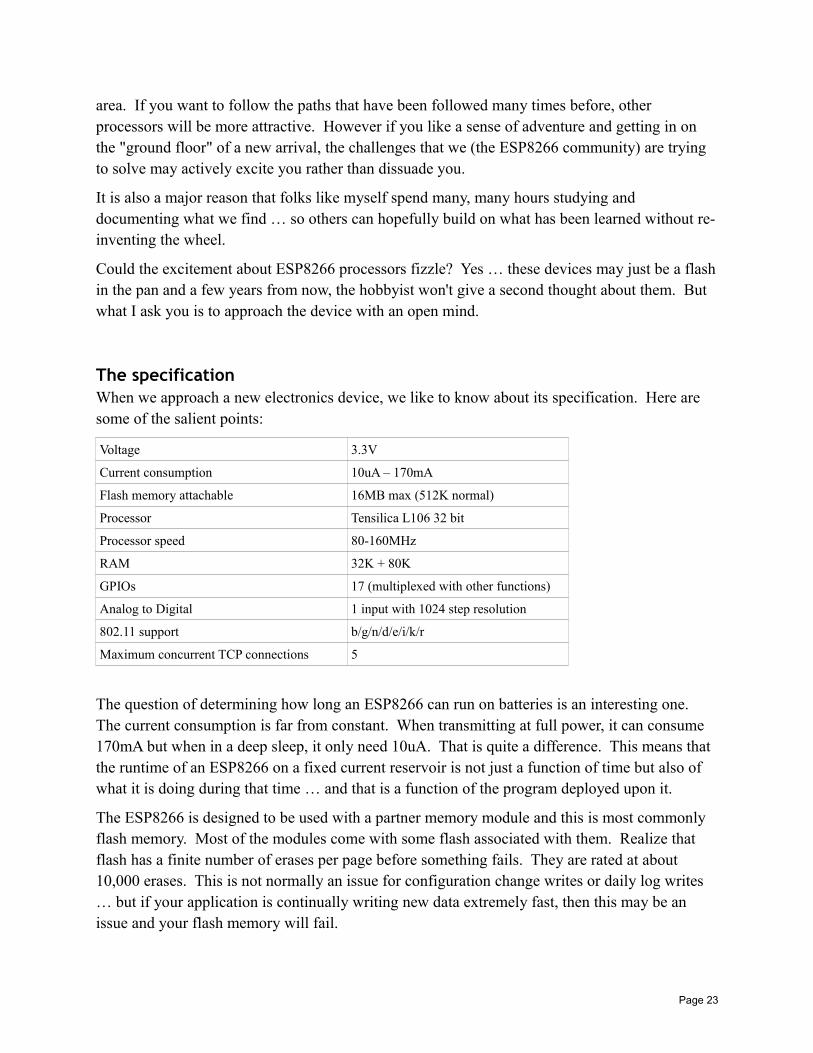
area. If you want to follow the paths that have been followed many times before, other processors will be more attractive. However if you like a sense of adventure and getting in on the "ground floor" of a new arrival, the challenges that we (the ESP8266 community) are trying to solve may actively excite you rather than dissuade you.
It is also a major reason that folks like myself spend many, many hours studying and documenting what we find … so others can hopefully build on what has been learned without re-inventing the wheel.
Could the excitement about ESP8266 processors fizzle? Yes … these devices may just be a flashin the pan and a few years from now, the hobbyist won't give a second thought about them. But what I ask you is to approach the device with an open mind.
The specificationWhen we approach a new electronics device, we like to know about its specification. Here are some of the salient points:
Voltage 3.3V
Current consumption 10uA – 170mA
Flash memory attachable 16MB max (512K normal)
Processor Tensilica L106 32 bit
Processor speed 80-160MHz
RAM 32K + 80K
GPIOs 17 (multiplexed with other functions)
Analog to Digital 1 input with 1024 step resolution
802.11 support b/g/n/d/e/i/k/r
Maximum concurrent TCP connections 5
The question of determining how long an ESP8266 can run on batteries is an interesting one. The current consumption is far from constant. When transmitting at full power, it can consume 170mA but when in a deep sleep, it only need 10uA. That is quite a difference. This means that the runtime of an ESP8266 on a fixed current reservoir is not just a function of time but also of what it is doing during that time … and that is a function of the program deployed upon it.
The ESP8266 is designed to be used with a partner memory module and this is most commonly flash memory. Most of the modules come with some flash associated with them. Realize that flash has a finite number of erases per page before something fails. They are rated at about 10,000 erases. This is not normally an issue for configuration change writes or daily log writes … but if your application is continually writing new data extremely fast, then this may be an issue and your flash memory will fail.
Page 23
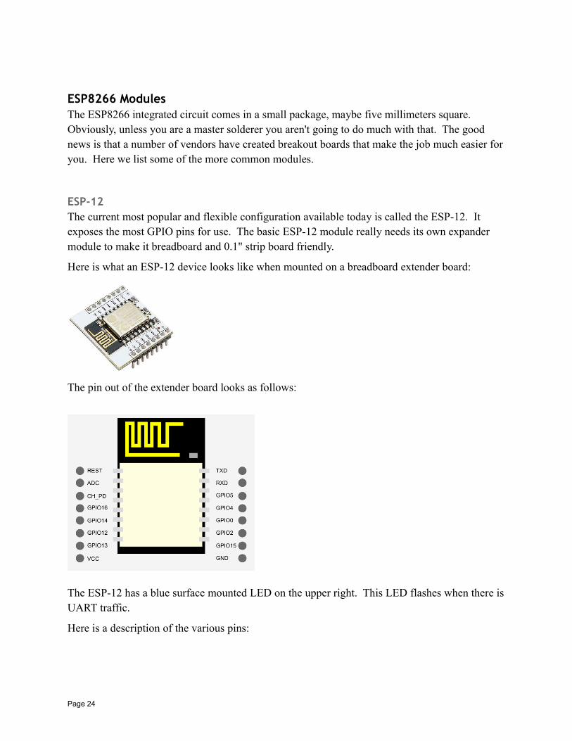
ESP8266 ModulesThe ESP8266 integrated circuit comes in a small package, maybe five millimeters square. Obviously, unless you are a master solderer you aren't going to do much with that. The good news is that a number of vendors have created breakout boards that make the job much easier foryou. Here we list some of the more common modules.
ESP-12The current most popular and flexible configuration available today is called the ESP-12. It exposes the most GPIO pins for use. The basic ESP-12 module really needs its own expander module to make it breadboard and 0.1" strip board friendly.
Here is what an ESP-12 device looks like when mounted on a breadboard extender board:
The pin out of the extender board looks as follows:
The ESP-12 has a blue surface mounted LED on the upper right. This LED flashes when there isUART traffic.
Here is a description of the various pins:
Page 24
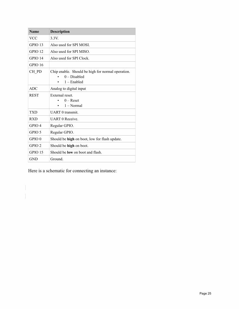
Name Description
VCC 3.3V.
GPIO 13 Also used for SPI MOSI.
GPIO 12 Also used for SPI MISO.
GPIO 14 Also used for SPI Clock.
GPIO 16
CH_PD Chip enable. Should be high for normal operation.• 0 – Disabled• 1 – Enabled
ADC Analog to digital input
REST External reset.• 0 – Reset• 1 – Normal
TXD UART 0 transmit.
RXD UART 0 Receive.
GPIO 4 Regular GPIO.
GPIO 5 Regular GPIO.
GPIO 0 Should be high on boot, low for flash update.
GPIO 2 Should be high on boot.
GPIO 15 Should be low on boot and flash.
GND Ground.
Here is a schematic for connecting an instance:
Page 25
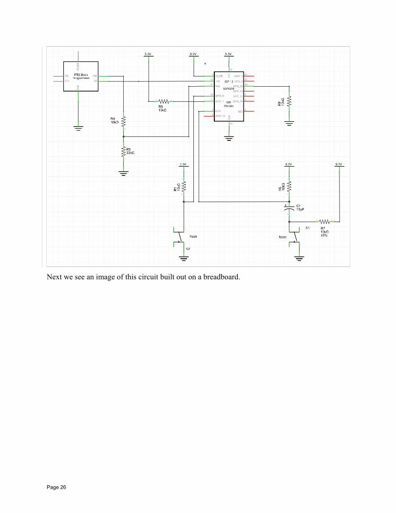
Next we see an image of this circuit built out on a breadboard.
Page 26
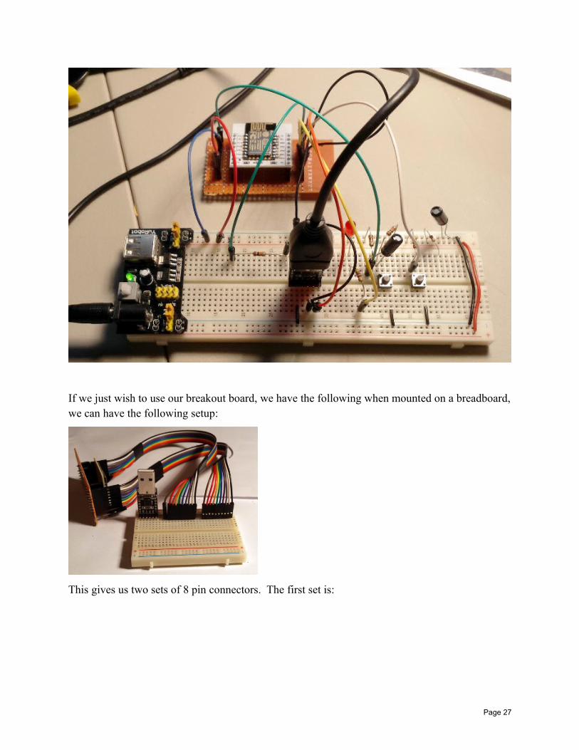
If we just wish to use our breakout board, we have the following when mounted on a breadboard,we can have the following setup:
This gives us two sets of 8 pin connectors. The first set is:
Page 27
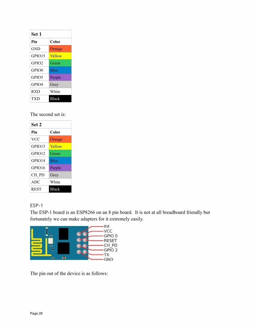
Set 1
Pin Color
GND Orange
GPIO15 Yellow
GPIO2 Green
GPIO0 Blue
GPIO5 Purple
GPIO4 Grey
RXD White
TXD Black
The second set is:
Set 2
Pin Color
VCC Orange
GPIO13 Yellow
GPIO12 Green
GPIO14 Blue
GPIO16 Purple
CH_PD Grey
ADC White
REST Black
ESP-1The ESP-1 board is an ESP8266 on an 8 pin board. It is not at all breadboard friendly but fortunately we can make adapters for it extremely easily.
The pin out of the device is as follows:
Page 28
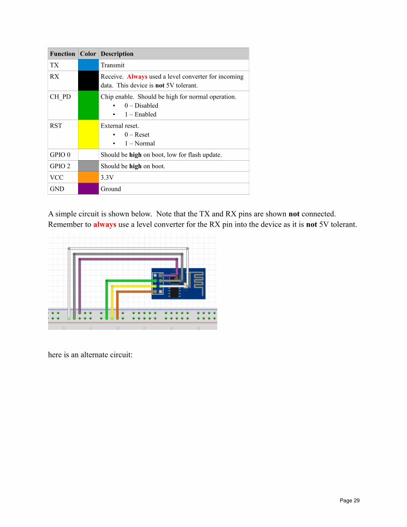
Function Color Description
TX Transmit
RX Receive. Always used a level converter for incoming data. This device is not 5V tolerant.
CH_PD Chip enable. Should be high for normal operation.• 0 – Disabled• 1 – Enabled
RST External reset.• 0 – Reset• 1 – Normal
GPIO 0 Should be high on boot, low for flash update.
GPIO 2 Should be high on boot.
VCC 3.3V
GND Ground
A simple circuit is shown below. Note that the TX and RX pins are shown not connected. Remember to always use a level converter for the RX pin into the device as it is not 5V tolerant.
here is an alternate circuit:
Page 29
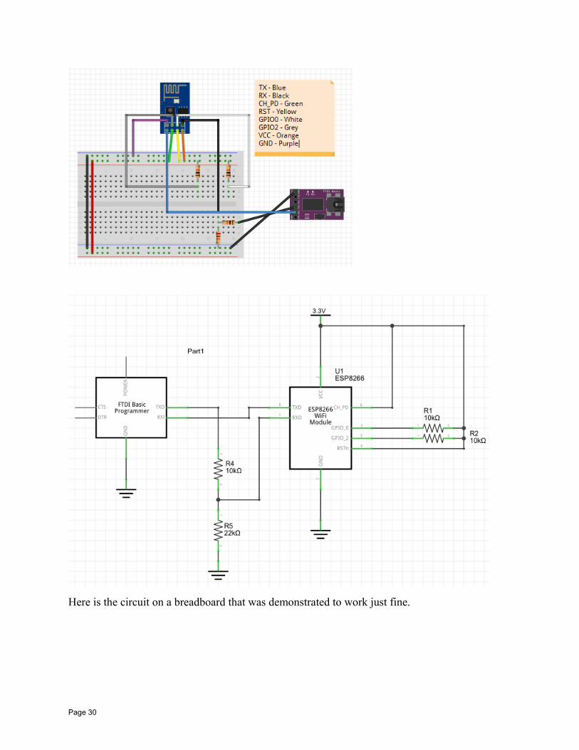
Here is the circuit on a breadboard that was demonstrated to work just fine.
Page 30
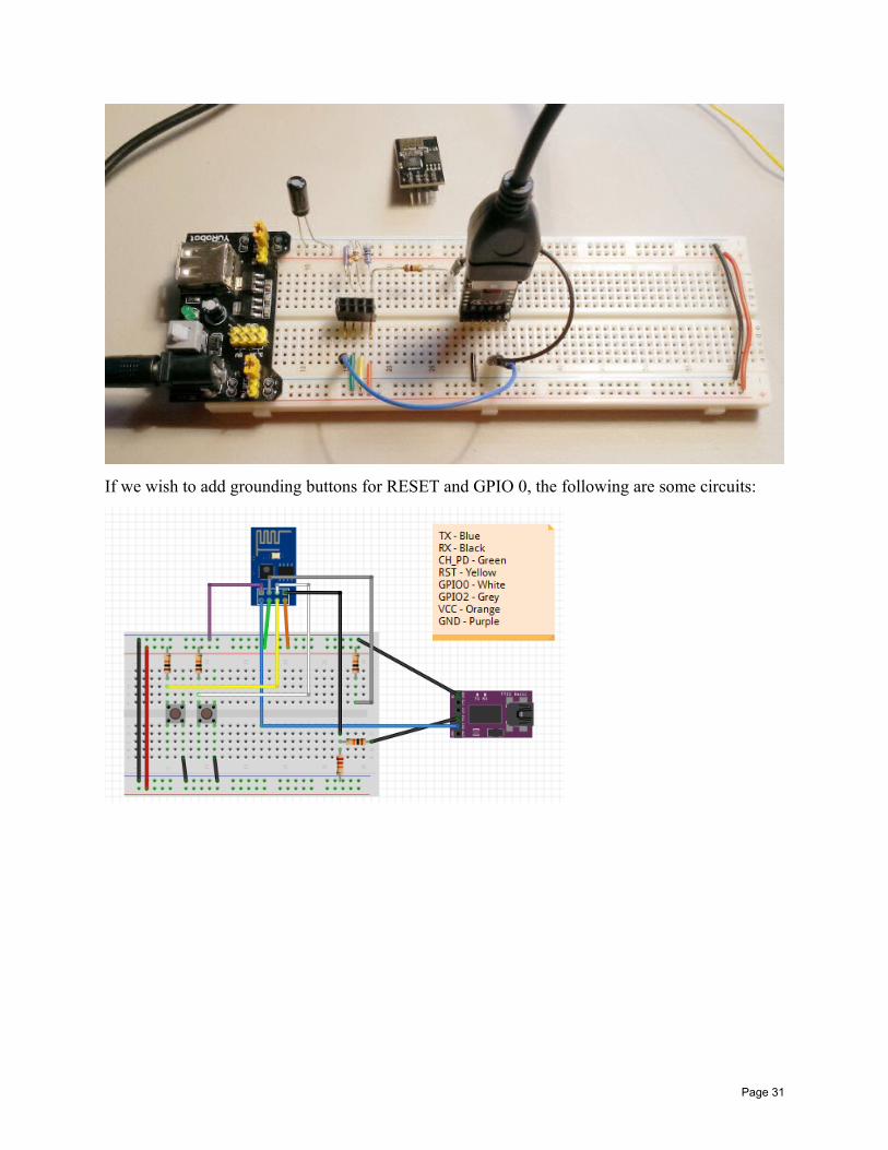
If we wish to add grounding buttons for RESET and GPIO 0, the following are some circuits:
Page 31
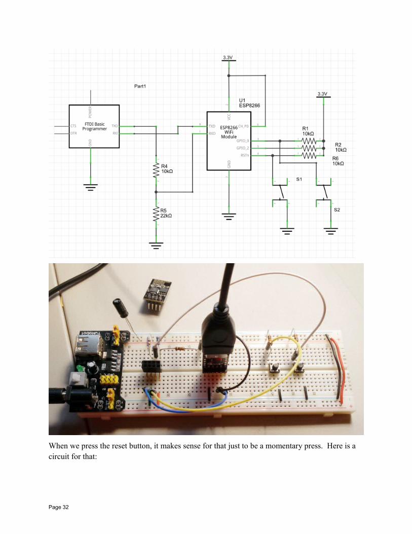
When we press the reset button, it makes sense for that just to be a momentary press. Here is a circuit for that:
Page 32
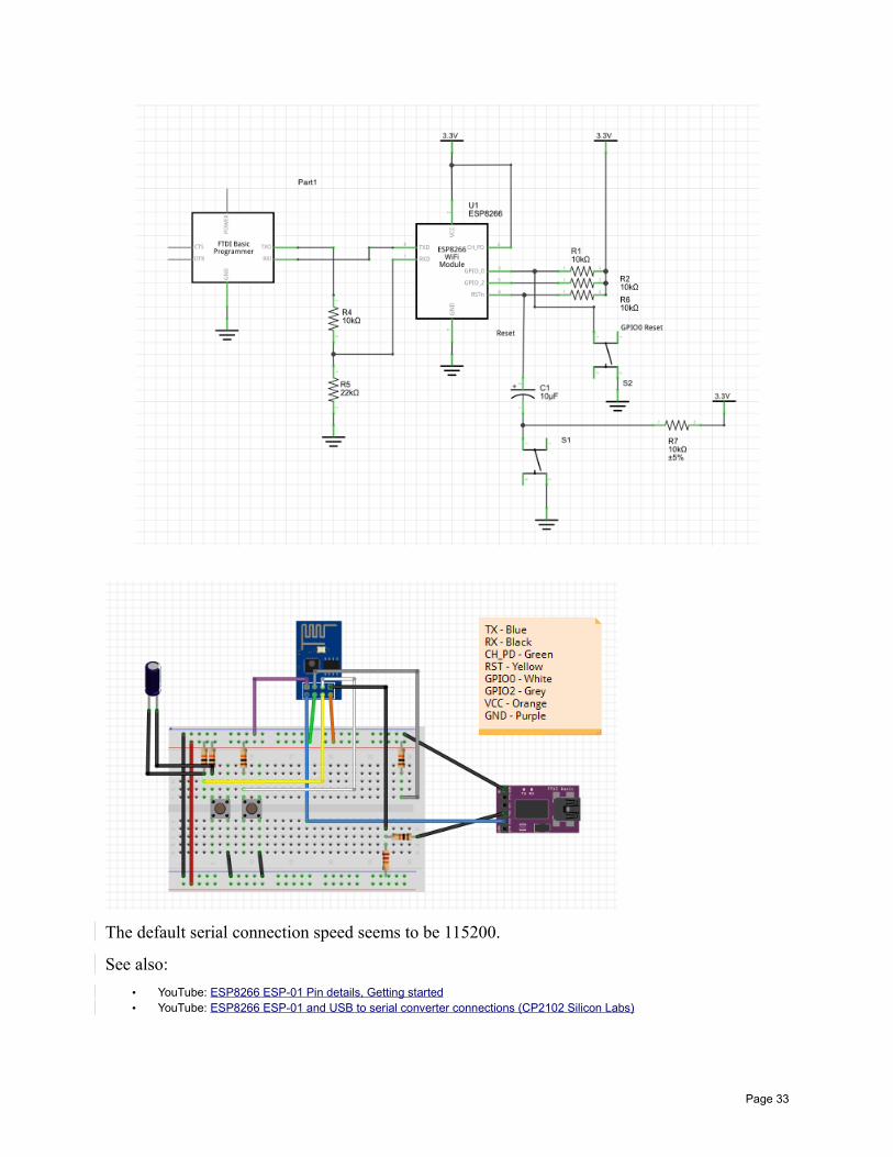
The default serial connection speed seems to be 115200.
See also:
• YouTube: ESP8266 ESP-01 Pin details, Getting started• YouTube: ESP8266 ESP-01 and USB to serial converter connections (CP2102 Silicon Labs)
Page 33
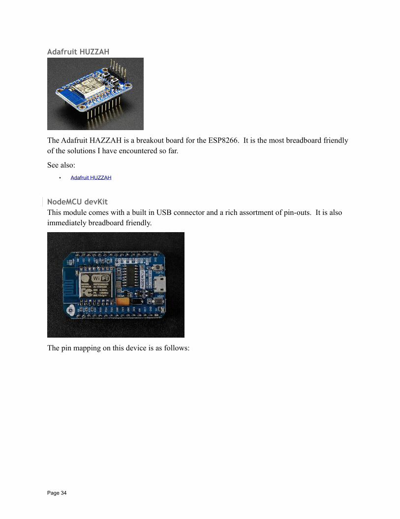
Adafruit HUZZAH
The Adafruit HAZZAH is a breakout board for the ESP8266. It is the most breadboard friendly of the solutions I have encountered so far.
See also:
• Adafruit HUZZAH
NodeMCU devKitThis module comes with a built in USB connector and a rich assortment of pin-outs. It is also immediately breadboard friendly.
The pin mapping on this device is as follows:
Page 34
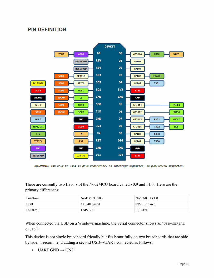
There are currently two flavors of the NodeMCU board called v0.9 and v1.0. Here are the primary differences:
Function NodeMCU v0.9 NodeMCU v1.0
USB CH340 based CP2012 based
ESP8266 ESP-12E ESP-12E
When connected via USB on a Windows machine, the Serial connector shows as "USB-SERIAL CH340".
This device is not single breadboard friendly but fits beautifully on two breadboards that are side by side. I recommend adding a second USB→UART connected as follows:
• UART GND → GND
Page 35
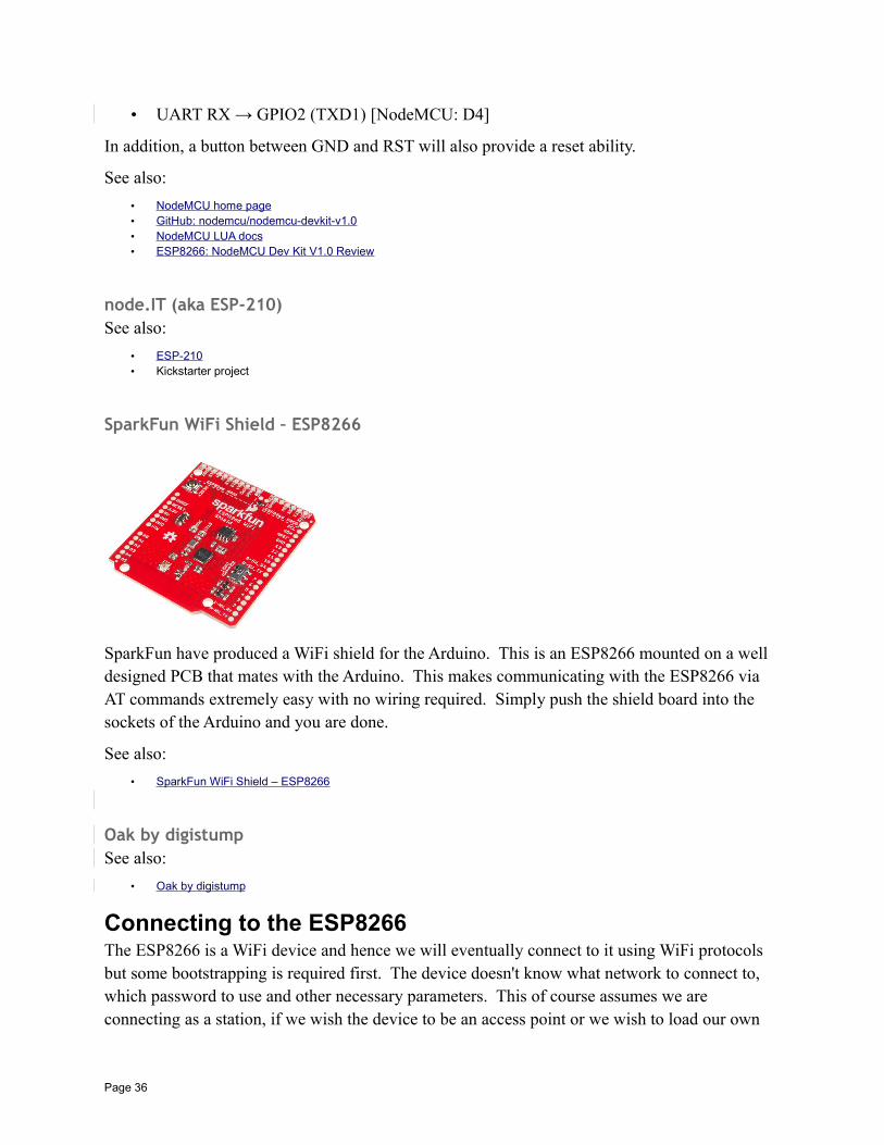
• UART RX → GPIO2 (TXD1) [NodeMCU: D4]
In addition, a button between GND and RST will also provide a reset ability.
See also:
• NodeMCU home page• GitHub: nodemcu/nodemcu-devkit-v1.0• NodeMCU LUA docs• ESP8266: NodeMCU Dev Kit V1.0 Review
node.IT (aka ESP-210)See also:
• ESP-210• Kickstarter project
SparkFun WiFi Shield – ESP8266
SparkFun have produced a WiFi shield for the Arduino. This is an ESP8266 mounted on a well designed PCB that mates with the Arduino. This makes communicating with the ESP8266 via AT commands extremely easy with no wiring required. Simply push the shield board into the sockets of the Arduino and you are done.
See also:
• SparkFun WiFi Shield – ESP8266
Oak by digistumpSee also:
• Oak by digistump
Connecting to the ESP8266The ESP8266 is a WiFi device and hence we will eventually connect to it using WiFi protocols but some bootstrapping is required first. The device doesn't know what network to connect to, which password to use and other necessary parameters. This of course assumes we are connecting as a station, if we wish the device to be an access point or we wish to load our own
Page 36
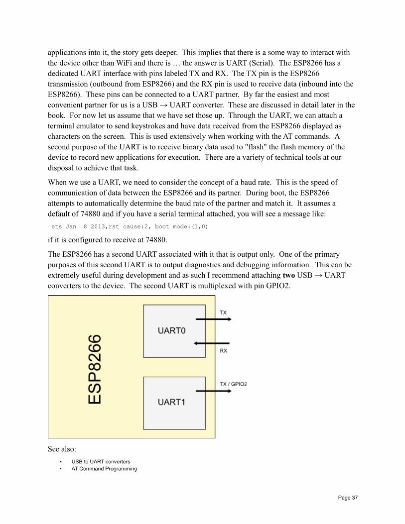
applications into it, the story gets deeper. This implies that there is a some way to interact with the device other than WiFi and there is … the answer is UART (Serial). The ESP8266 has a dedicated UART interface with pins labeled TX and RX. The TX pin is the ESP8266 transmission (outbound from ESP8266) and the RX pin is used to receive data (inbound into the ESP8266). These pins can be connected to a UART partner. By far the easiest and most convenient partner for us is a USB → UART converter. These are discussed in detail later in the book. For now let us assume that we have set those up. Through the UART, we can attach a terminal emulator to send keystrokes and have data received from the ESP8266 displayed as characters on the screen. This is used extensively when working with the AT commands. A second purpose of the UART is to receive binary data used to "flash" the flash memory of the device to record new applications for execution. There are a variety of technical tools at our disposal to achieve that task.
When we use a UART, we need to consider the concept of a baud rate. This is the speed of communication of data between the ESP8266 and its partner. During boot, the ESP8266 attempts to automatically determine the baud rate of the partner and match it. It assumes a default of 74880 and if you have a serial terminal attached, you will see a message like:
ets Jan 8 2013,rst cause:2, boot mode:(1,0)
if it is configured to receive at 74880.
The ESP8266 has a second UART associated with it that is output only. One of the primary purposes of this second UART is to output diagnostics and debugging information. This can be extremely useful during development and as such I recommend attaching two USB → UART converters to the device. The second UART is multiplexed with pin GPIO2.
See also:
• USB to UART converters• AT Command Programming
Page 37
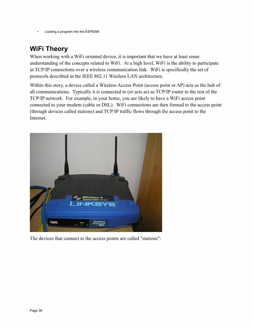
• Loading a program into the ESP8266
WiFi TheoryWhen working with a WiFi oriented device, it is important that we have at least some understanding of the concepts related to WiFi. At a high level, WiFi is the ability to participate in TCP/IP connections over a wireless communication link. WiFi is specifically the set of protocols described in the IEEE 802.11 Wireless LAN architecture.
Within this story, a device called a Wireless Access Point (access point or AP) acts as the hub of all communications. Typically it is connected to (or acts as) as TCP/IP router to the rest of the TCP/IP network. For example, in your home, you are likely to have a WiFi access point connected to your modem (cable or DSL). WiFi connections are then formed to the access point (through devices called stations) and TCP/IP traffic flows through the access point to the Internet.
The devices that connect to the access points are called "stations":
Page 38
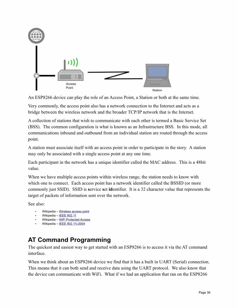
An ESP8266 device can play the role of an Access Point, a Station or both at the same time.
Very commonly, the access point also has a network connection to the Internet and acts as a bridge between the wireless network and the broader TCP/IP network that is the Internet.
A collection of stations that wish to communicate with each other is termed a Basic Service Set (BSS). The common configuration is what is known as an Infrastructure BSS. In this mode, all communications inbound and outbound from an individual station are routed through the access point.
A station must associate itself with an access point in order to participate in the story. A station may only be associated with a single access point at any one time.
Each participant in the network has a unique identifier called the MAC address. This is a 48bit value.
When we have multiple access points within wireless range, the station needs to know with which one to connect. Each access point has a network identifier called the BSSID (or more commonly just SSID). SSID is service set identifier. It is a 32 character value that represents thetarget of packets of information sent over the network.
See also:
• Wikipedia – Wireless access point• Wikipedia – IEEE 802.11• Wikipedia – WiFi Protected Access• Wikipedia – IEEE 802.11i-2004
AT Command ProgrammingThe quickest and easiest way to get started with an ESP8266 is to access it via the AT command interface.
When we think about an ESP8266 device we find that it has a built in UART (Serial) connection.This means that it can both send and receive data using the UART protocol. We also know that the device can communicate with WiFi. What if we had an application that ran on the ESP8266
Page 39
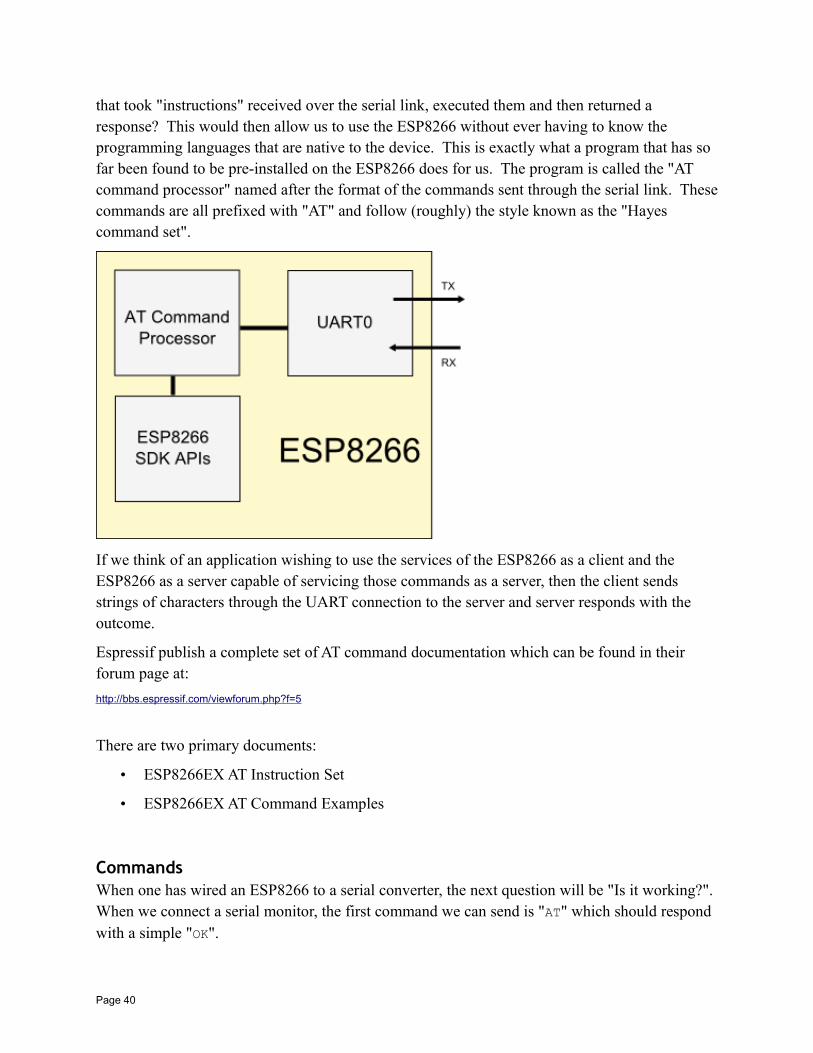
that took "instructions" received over the serial link, executed them and then returned a response? This would then allow us to use the ESP8266 without ever having to know the programming languages that are native to the device. This is exactly what a program that has so far been found to be pre-installed on the ESP8266 does for us. The program is called the "AT command processor" named after the format of the commands sent through the serial link. Thesecommands are all prefixed with "AT" and follow (roughly) the style known as the "Hayes command set".
If we think of an application wishing to use the services of the ESP8266 as a client and the ESP8266 as a server capable of servicing those commands as a server, then the client sends strings of characters through the UART connection to the server and server responds with the outcome.
Espressif publish a complete set of AT command documentation which can be found in their forum page at:
http://bbs.espressif.com/viewforum.php?f=5
There are two primary documents:
• ESP8266EX AT Instruction Set
• ESP8266EX AT Command Examples
CommandsWhen one has wired an ESP8266 to a serial converter, the next question will be "Is it working?". When we connect a serial monitor, the first command we can send is "AT" which should respond with a simple "OK".
Page 40

An instruction passed to the device follows one of the following syntax options:
Type Format Description
Test AT+<x>=? Query the parameters and its range of values.
Query AT+<x>? Return the current value of the parameter.
Set AT+<x>=<...> Set the value of a parameter.
Execute AT+<x> Execute a command.
All "AT" instructions end with the "\r\n" pair.
Page 41
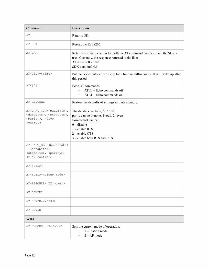
Command Description
AT Returns OK
AT+RST Restart the ESP8266.
AT+GMR Returns firmware version for both the AT command processor and the SDK in use. Currently, the response returned looks like:AT version:0.21.0.0SDK version:0.9.5
AT+GSLP=<time> Put the device into a deep sleep for a time in milliseconds. It will wake up after this period.
ATE[0|1] Echo AT commands.• ATE0 – Echo commands off• ATE1 – Echo commands on
AT+RESTORE Restore the defaults of settings in flash memory.
AT+UART_CUR=<baudrate>,<databits>, <stopbits>,<parity>, <flow control>
The databits can be 5, 6, 7 or 8.parity can be 0=none, 1=odd, 2=evenflowcontrol can be:0 – disable1 – enable RTS2 – enable CTS3 – enable both RTS and CTS
AT+UART_DEF=<baundrate>, <databits>, <stopbits>, <parity>, <flow control>
AT+SLEEP?
AT+SLEEP=<sleep mode>
AT+RFPOWER=<TX power>
AT+RFVDD?
AT+RFVDD=<VDD33>
AT+RFVDD
WIFI
AT+CWMODE_CUR=<mode> Sets the current mode of operation.• 1 – Station mode• 2 – AP mode
Page 42
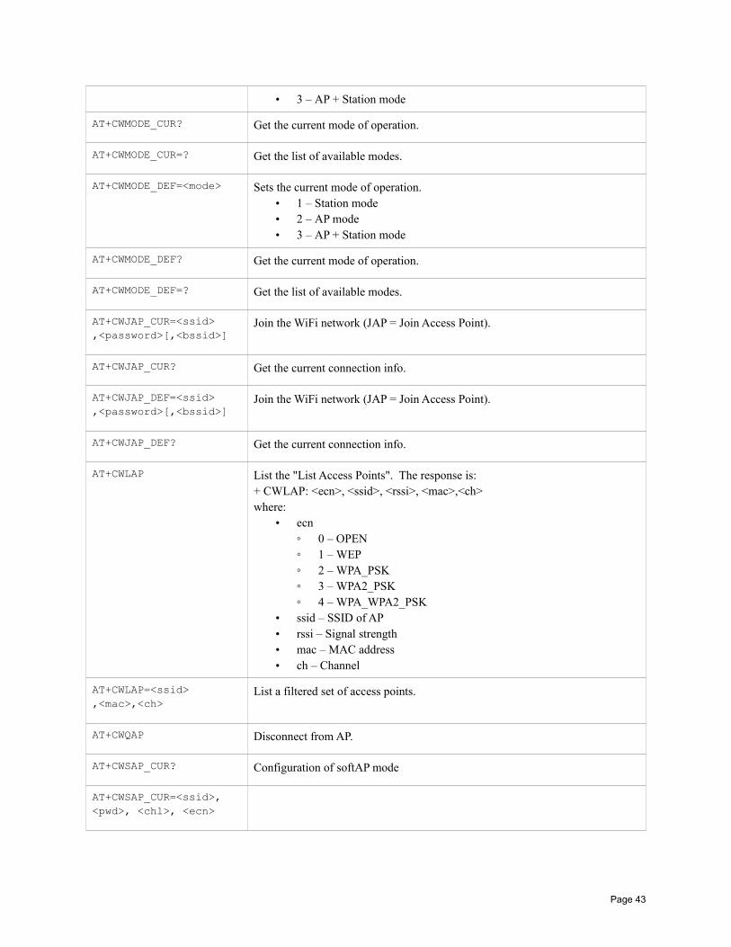
• 3 – AP + Station mode
AT+CWMODE_CUR? Get the current mode of operation.
AT+CWMODE_CUR=? Get the list of available modes.
AT+CWMODE_DEF=<mode> Sets the current mode of operation.• 1 – Station mode• 2 – AP mode• 3 – AP + Station mode
AT+CWMODE_DEF? Get the current mode of operation.
AT+CWMODE_DEF=? Get the list of available modes.
AT+CWJAP_CUR=<ssid> ,<password>[,<bssid>]
Join the WiFi network (JAP = Join Access Point).
AT+CWJAP_CUR? Get the current connection info.
AT+CWJAP_DEF=<ssid> ,<password>[,<bssid>]
Join the WiFi network (JAP = Join Access Point).
AT+CWJAP_DEF? Get the current connection info.
AT+CWLAP List the "List Access Points". The response is:+ CWLAP: <ecn>, <ssid>, <rssi>, <mac>,<ch>where:
• ecn 0 – OPEN 1 – WEP 2 – WPA_PSK 3 – WPA2_PSK 4 – WPA_WPA2_PSK
• ssid – SSID of AP• rssi – Signal strength• mac – MAC address• ch – Channel
AT+CWLAP=<ssid> ,<mac>,<ch>
List a filtered set of access points.
AT+CWQAP Disconnect from AP.
AT+CWSAP_CUR? Configuration of softAP mode
AT+CWSAP_CUR=<ssid>, <pwd>, <chl>, <ecn>
Page 43
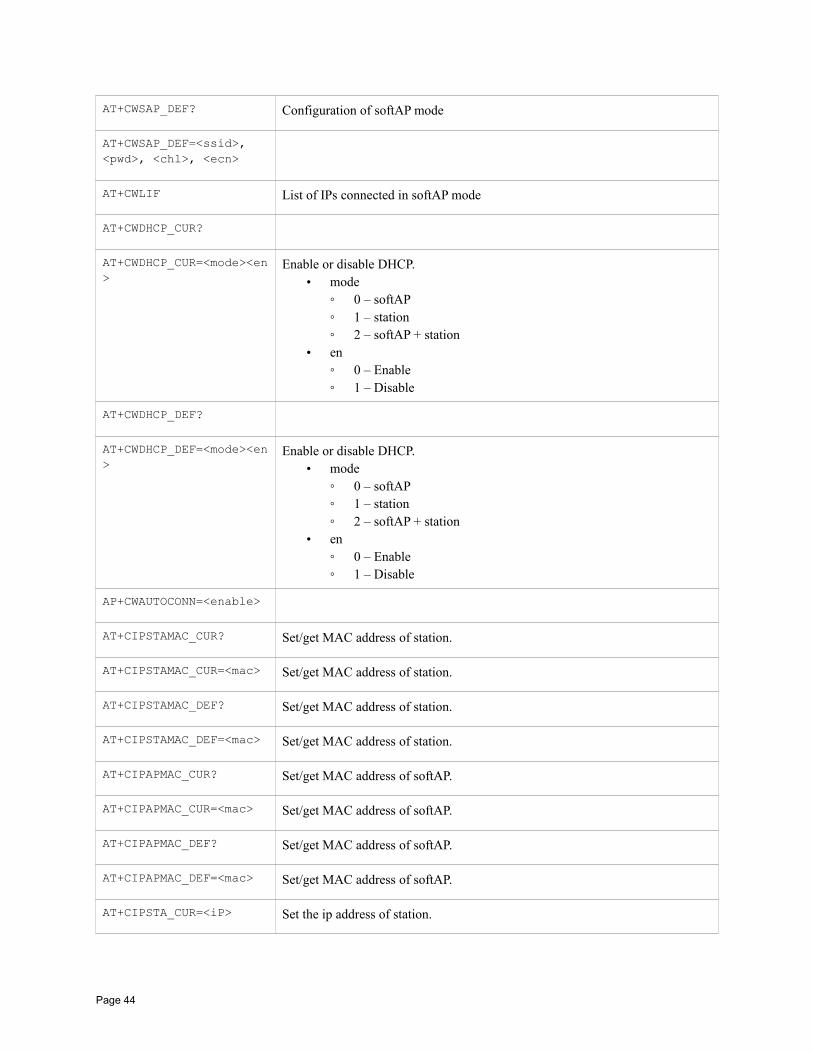
AT+CWSAP_DEF? Configuration of softAP mode
AT+CWSAP_DEF=<ssid>, <pwd>, <chl>, <ecn>
AT+CWLIF List of IPs connected in softAP mode
AT+CWDHCP_CUR?
AT+CWDHCP_CUR=<mode><en>
Enable or disable DHCP.• mode
0 – softAP 1 – station 2 – softAP + station
• en 0 – Enable 1 – Disable
AT+CWDHCP_DEF?
AT+CWDHCP_DEF=<mode><en>
Enable or disable DHCP.• mode
0 – softAP 1 – station 2 – softAP + station
• en 0 – Enable 1 – Disable
AP+CWAUTOCONN=<enable>
AT+CIPSTAMAC_CUR? Set/get MAC address of station.
AT+CIPSTAMAC_CUR=<mac> Set/get MAC address of station.
AT+CIPSTAMAC_DEF? Set/get MAC address of station.
AT+CIPSTAMAC_DEF=<mac> Set/get MAC address of station.
AT+CIPAPMAC_CUR? Set/get MAC address of softAP.
AT+CIPAPMAC_CUR=<mac> Set/get MAC address of softAP.
AT+CIPAPMAC_DEF? Set/get MAC address of softAP.
AT+CIPAPMAC_DEF=<mac> Set/get MAC address of softAP.
AT+CIPSTA_CUR=<iP> Set the ip address of station.
Page 44
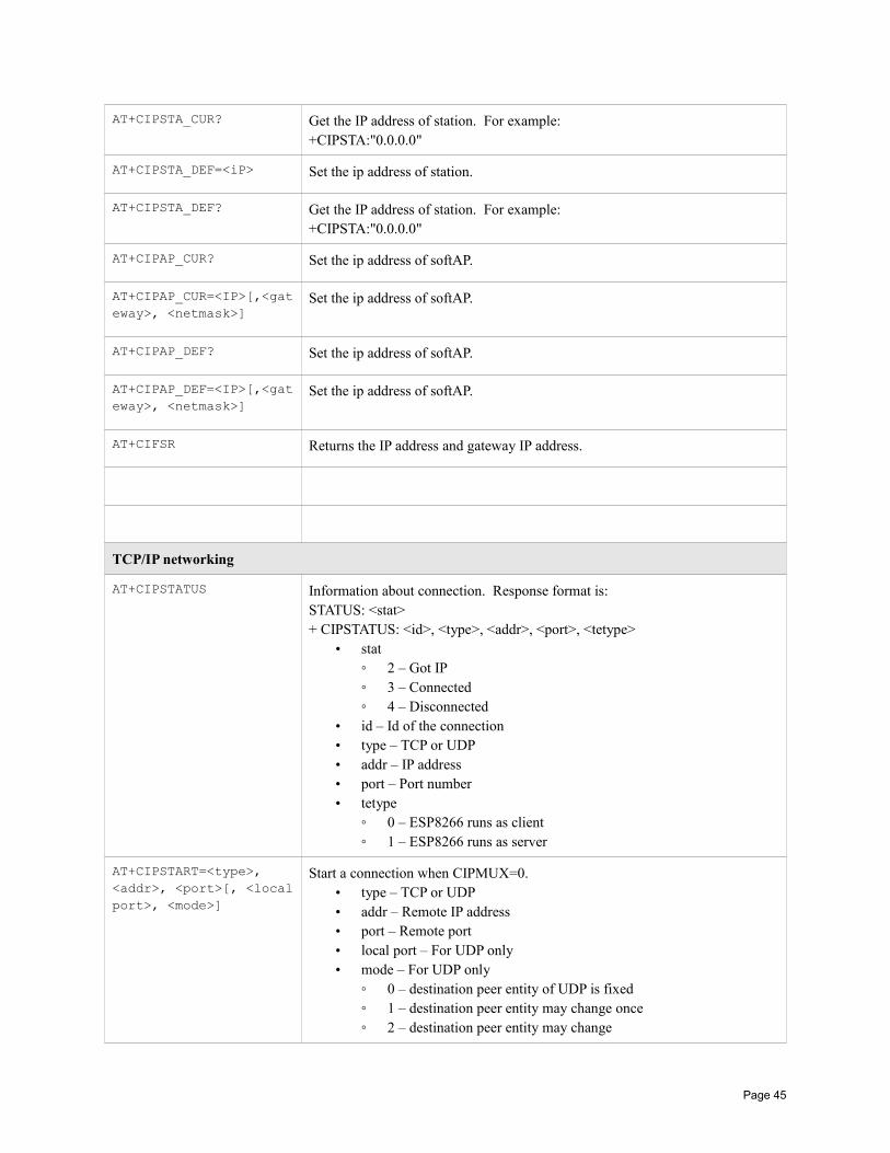
AT+CIPSTA_CUR? Get the IP address of station. For example:+CIPSTA:"0.0.0.0"
AT+CIPSTA_DEF=<iP> Set the ip address of station.
AT+CIPSTA_DEF? Get the IP address of station. For example:+CIPSTA:"0.0.0.0"
AT+CIPAP_CUR? Set the ip address of softAP.
AT+CIPAP_CUR=<IP>[,<gateway>, <netmask>]
Set the ip address of softAP.
AT+CIPAP_DEF? Set the ip address of softAP.
AT+CIPAP_DEF=<IP>[,<gateway>, <netmask>]
Set the ip address of softAP.
AT+CIFSR Returns the IP address and gateway IP address.
TCP/IP networking
AT+CIPSTATUS Information about connection. Response format is:STATUS: <stat>+ CIPSTATUS: <id>, <type>, <addr>, <port>, <tetype>
• stat 2 – Got IP 3 – Connected 4 – Disconnected
• id – Id of the connection• type – TCP or UDP• addr – IP address• port – Port number• tetype
0 – ESP8266 runs as client 1 – ESP8266 runs as server
AT+CIPSTART=<type>, <addr>, <port>[, <localport>, <mode>]
Start a connection when CIPMUX=0.• type – TCP or UDP• addr – Remote IP address• port – Remote port• local port – For UDP only• mode – For UDP only
0 – destination peer entity of UDP is fixed 1 – destination peer entity may change once 2 – destination peer entity may change
Page 45
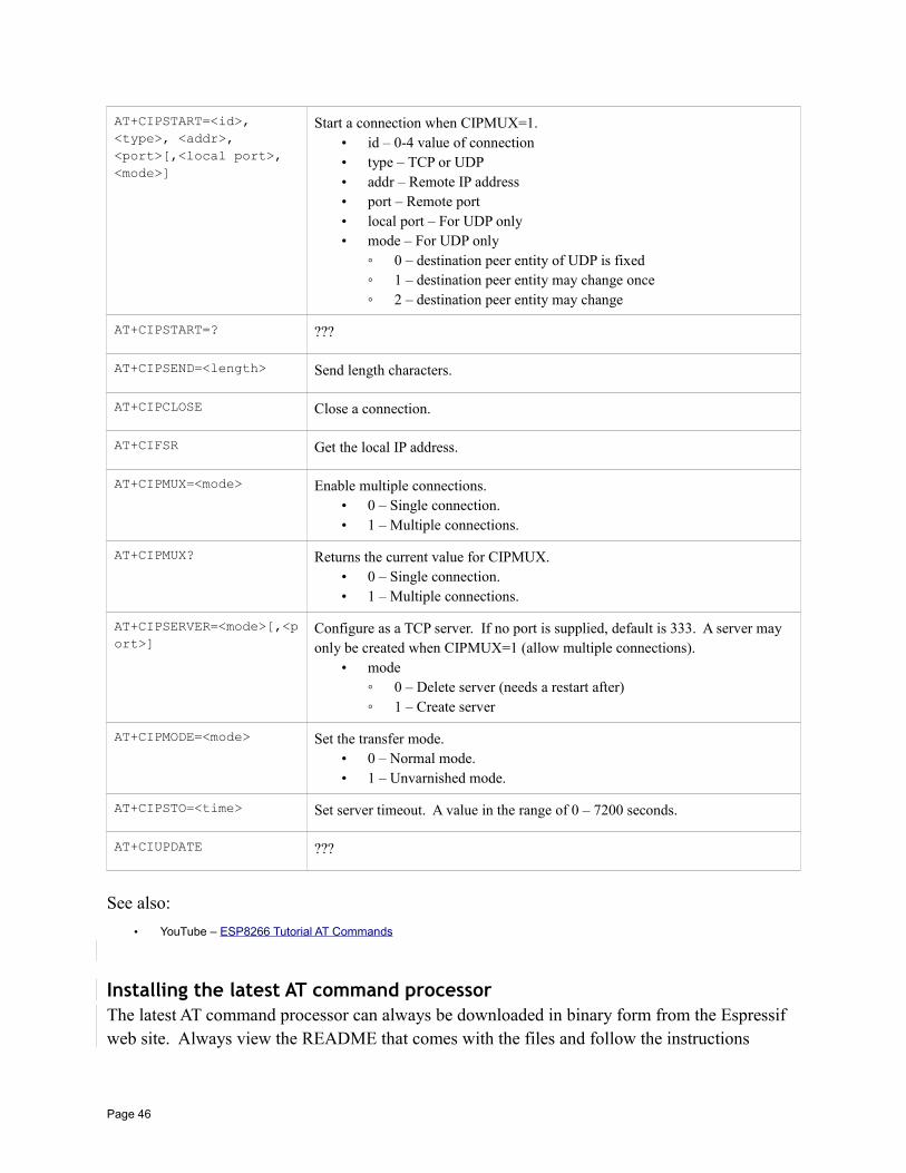
AT+CIPSTART=<id>, <type>, <addr>, <port>[,<local port>, <mode>]
Start a connection when CIPMUX=1.• id – 0-4 value of connection• type – TCP or UDP• addr – Remote IP address• port – Remote port• local port – For UDP only• mode – For UDP only
0 – destination peer entity of UDP is fixed 1 – destination peer entity may change once 2 – destination peer entity may change
AT+CIPSTART=? ???
AT+CIPSEND=<length> Send length characters.
AT+CIPCLOSE Close a connection.
AT+CIFSR Get the local IP address.
AT+CIPMUX=<mode> Enable multiple connections.• 0 – Single connection.• 1 – Multiple connections.
AT+CIPMUX? Returns the current value for CIPMUX.• 0 – Single connection.• 1 – Multiple connections.
AT+CIPSERVER=<mode>[,<port>]
Configure as a TCP server. If no port is supplied, default is 333. A server may only be created when CIPMUX=1 (allow multiple connections).
• mode 0 – Delete server (needs a restart after) 1 – Create server
AT+CIPMODE=<mode> Set the transfer mode.• 0 – Normal mode.• 1 – Unvarnished mode.
AT+CIPSTO=<time> Set server timeout. A value in the range of 0 – 7200 seconds.
AT+CIUPDATE ???
See also:
• YouTube – ESP8266 Tutorial AT Commands
Installing the latest AT command processorThe latest AT command processor can always be downloaded in binary form from the Espressif web site. Always view the README that comes with the files and follow the instructions
Page 46
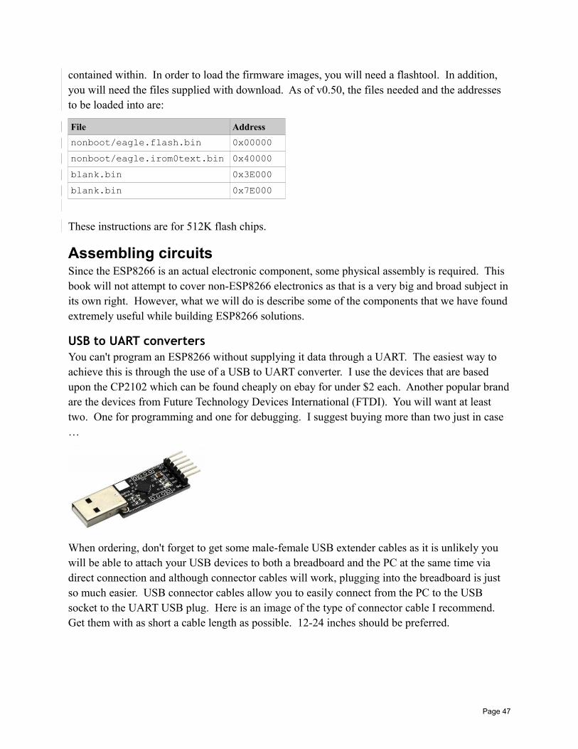
contained within. In order to load the firmware images, you will need a flashtool. In addition, you will need the files supplied with download. As of v0.50, the files needed and the addresses to be loaded into are:
File Address
nonboot/eagle.flash.bin 0x00000
nonboot/eagle.irom0text.bin 0x40000
blank.bin 0x3E000
blank.bin 0x7E000
These instructions are for 512K flash chips.
Assembling circuitsSince the ESP8266 is an actual electronic component, some physical assembly is required. This book will not attempt to cover non-ESP8266 electronics as that is a very big and broad subject inits own right. However, what we will do is describe some of the components that we have found extremely useful while building ESP8266 solutions.
USB to UART convertersYou can't program an ESP8266 without supplying it data through a UART. The easiest way to achieve this is through the use of a USB to UART converter. I use the devices that are based upon the CP2102 which can be found cheaply on ebay for under $2 each. Another popular brandare the devices from Future Technology Devices International (FTDI). You will want at least two. One for programming and one for debugging. I suggest buying more than two just in case …
When ordering, don't forget to get some male-female USB extender cables as it is unlikely you will be able to attach your USB devices to both a breadboard and the PC at the same time via direct connection and although connector cables will work, plugging into the breadboard is just so much easier. USB connector cables allow you to easily connect from the PC to the USB socket to the UART USB plug. Here is an image of the type of connector cable I recommend. Get them with as short a cable length as possible. 12-24 inches should be preferred.
Page 47

When we plug in a USB → UART into a Windows machine, we can learn the COM port that the new serial port appears upon by opening the Windows Device Manager. There are a number of ways of doing this, one way is to launch it from the DOS command window with:
mmc devmgmt.msc
Under the section called Ports (COM & LPT) you will find entries for each of the COM ports. The COM ports don't provide you a mapping that a particular USB socket is hosting a particular COM port so my poor suggestion is to pull the USB from each socket one by one and make a note of which COM port disappears (or appears if you are inserting a USB).
See also:
Page 48

• Connecting to the ESP8266• Working with serial
BreadboardsI find I can never have too many breadboards. I suggest getting a few full size and half size boards along with some 24 AWG connector wire and a good pair of wire strippers. Keep a trash bin close by otherwise you will find yourself knee deep in stripped insulation and cut wire parts before you know it. I also recommend some Dupont male-male pre-made wires. Ribbon cable can also be useful.
PowerWe need electricity to get these devices working. I choose the MB102 breadboard attachable power adapters. These can be powered from an ordinary wall-wart (mains adapter) or from USB. It appears that the plug for wall-wart power is 2.1mm and center positive however I strongly suggest that you read your specific supplier's data sheets very carefully. There is also a potential concern that the barrel socket is wired in parallel with the USB input which could meanthat if you attach a high voltage input (eg. 12V) while also having a USB source connected, you may very well damage your USB device. The devices have a master on/off power switch plus a jumper to set 3.3V or 5V outputs. You can even have one breadboard rail be 3.3V and the other 5V … but take care not to apply 5V to your ESP8266. By having two power rails, one at 3.3V and the other at 5V, you can power both the ESP8266 and devices/circuits that require 5V.
When the ESP8266 starts to transmit over wireless, that can draw a lot of current which can cause ripples in your power supply. You may also have other sensors or devices connected to your supply as well. These fluctuations in the voltage can cause problems. It is strongly recommended that you place a 10 micro farad capacitor between +ve and -ve as close to your
Page 49

ESP8266 as you can. This will provide a reservoir of power to even out any transient ripples. This is one of those tips that you ignore at your peril. Everything may work just fine without the capacitor … until it doesn't or until you start getting intermittent problems and are at a loss to explain them. Let me put it this way, for the few cents it costs and the zero harm it does, why not?
Multi-meter / Logic probe / Logic AnalyzerWhen your circuit doesn't work and you are staring at it wondering what is wrong, you will be thankful if you have a multi-meter and a logic probe. If your budget will stretch, I also recommend a USB based logic analyzer such as those made by Saleae. These allow you to monitor the signals coming into or being produced by your ESP8266. Think of this as the best source of debugging available to you.
See also:
• Saleae logic analyzers
Sundry componentsYou will want the usual set of suspects for sundry components including LEDs, resistors, capacitors and more.
Physical constructionWhen you have breadboarded your circuit and written your application, there may come a time where you wish to make your solution permanent. At that point, you will need a soldering iron, solder and some strip-board. I also recommend some female header sockets so that you don't have to solder your ESP8266s directly into the circuits. Not only does this allow you to reuse thedevices (should you desire) but in the unfortunate event that you fry one, it will be easier to replace.
Page 50
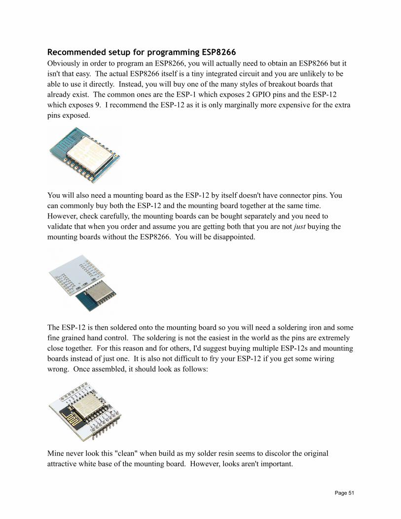
Recommended setup for programming ESP8266Obviously in order to program an ESP8266, you will actually need to obtain an ESP8266 but it isn't that easy. The actual ESP8266 itself is a tiny integrated circuit and you are unlikely to be able to use it directly. Instead, you will buy one of the many styles of breakout boards that already exist. The common ones are the ESP-1 which exposes 2 GPIO pins and the ESP-12 which exposes 9. I recommend the ESP-12 as it is only marginally more expensive for the extra pins exposed.
You will also need a mounting board as the ESP-12 by itself doesn't have connector pins. You can commonly buy both the ESP-12 and the mounting board together at the same time. However, check carefully, the mounting boards can be bought separately and you need to validate that when you order and assume you are getting both that you are not just buying the mounting boards without the ESP8266. You will be disappointed.
The ESP-12 is then soldered onto the mounting board so you will need a soldering iron and somefine grained hand control. The soldering is not the easiest in the world as the pins are extremely close together. For this reason and for others, I'd suggest buying multiple ESP-12s and mountingboards instead of just one. It is also not difficult to fry your ESP-12 if you get some wiring wrong. Once assembled, it should look as follows:
Mine never look this "clean" when build as my solder resin seems to discolor the original attractive white base of the mounting board. However, looks aren't important.
Page 51

Assuming you now have a mounted ESP-12 with pins, your next question will be "now what"? This is where you will want a few breadboards and connector wire. You could use dupont connectors with female sockets attached to the ESP-12 and male pins on the other to attach to your breadboard but you will find that wires inevitably come loose at the worse possible times. You can mount the ESP-12 to a breadboard but I tend to find that there is not enough space for connector wires underneath it.
Once secured, I recommend two USB → UART connectors. Why two? One dedicated for flashing the device and one for debugging.
For power, I recommend using MB102 breadboard power supplies however, make sure that you set the jumper cables to be 3.3V. You will ruin your ESP8266 if you try and power it at 5V.
Once it is all wired up, you will need a PC with two open USB ports.
Parts list
• Breadboards – 2 half size – $3.50 for 2
• ESP-12 plus mounting boards – 3 sets – $3.80 each – $11.40
• CP2102 USB → UARTs – 2 pieces - $3.10
• USB male to female extenders – 2 pieces – $1.00 each – $2.00
• 24 AWG wire – 5 meters for $1.12
• 8pin 2.54mm stackable long legged female headers – 10 pieces for $3.95
• Red diffuse LEDs – A handful – $1.00
• Resistors – Some 10K, some 20K, some 330Ohm – A handful – $1.00
• Capacitors – Some 10 micro farad – $1.00
All told, it comes to about $30 + some shipping. I buy all my components through ebay from Chinese suppliers that give me the price/quality I am looking for. The name of the game though is patience. Once you order it usually takes 2-3 weeks for the parts to arrive so be patient and use the time to watch you-tube videos on electronics projects and the relevant community forums.
Eventually, you are likely going to want to build a permanent circuit for your development. On astrip board the circuit I built looks like:
Page 52
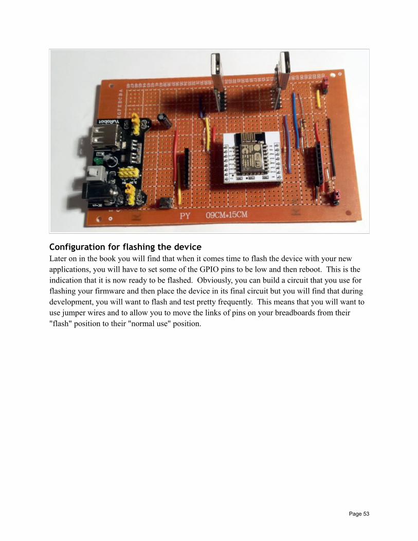
Configuration for flashing the deviceLater on in the book you will find that when it comes time to flash the device with your new applications, you will have to set some of the GPIO pins to be low and then reboot. This is the indication that it is now ready to be flashed. Obviously, you can build a circuit that you use for flashing your firmware and then place the device in its final circuit but you will find that during development, you will want to flash and test pretty frequently. This means that you will want to use jumper wires and to allow you to move the links of pins on your breadboards from their "flash" position to their "normal use" position.
Page 53
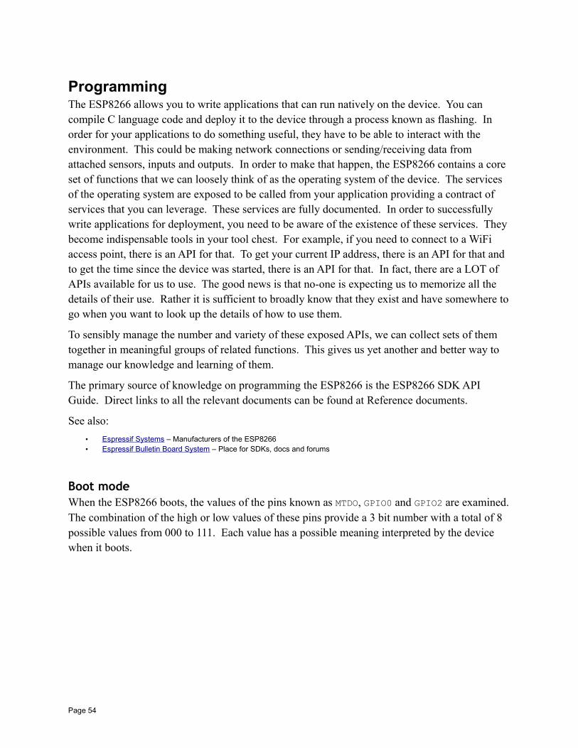
ProgrammingThe ESP8266 allows you to write applications that can run natively on the device. You can compile C language code and deploy it to the device through a process known as flashing. In order for your applications to do something useful, they have to be able to interact with the environment. This could be making network connections or sending/receiving data from attached sensors, inputs and outputs. In order to make that happen, the ESP8266 contains a core set of functions that we can loosely think of as the operating system of the device. The services of the operating system are exposed to be called from your application providing a contract of services that you can leverage. These services are fully documented. In order to successfully write applications for deployment, you need to be aware of the existence of these services. They become indispensable tools in your tool chest. For example, if you need to connect to a WiFi access point, there is an API for that. To get your current IP address, there is an API for that and to get the time since the device was started, there is an API for that. In fact, there are a LOT of APIs available for us to use. The good news is that no-one is expecting us to memorize all the details of their use. Rather it is sufficient to broadly know that they exist and have somewhere togo when you want to look up the details of how to use them.
To sensibly manage the number and variety of these exposed APIs, we can collect sets of them together in meaningful groups of related functions. This gives us yet another and better way to manage our knowledge and learning of them.
The primary source of knowledge on programming the ESP8266 is the ESP8266 SDK API Guide. Direct links to all the relevant documents can be found at Reference documents.
See also:
• Espressif Systems – Manufacturers of the ESP8266• Espressif Bulletin Board System – Place for SDKs, docs and forums
Boot modeWhen the ESP8266 boots, the values of the pins known as MTDO, GPIO0 and GPIO2 are examined.The combination of the high or low values of these pins provide a 3 bit number with a total of 8 possible values from 000 to 111. Each value has a possible meaning interpreted by the device when it boots.
Page 54
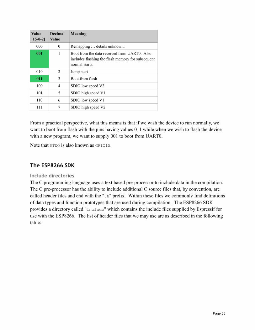
Value[15-0-2]
DecimalValue
Meaning
000 0 Remapping … details unknown.
001 1 Boot from the data received from UART0. Also includes flashing the flash memory for subsequent normal starts.
010 2 Jump start
011 3 Boot from flash
100 4 SDIO low speed V2
101 5 SDIO high speed V1
110 6 SDIO low speed V1
111 7 SDIO high speed V2
From a practical perspective, what this means is that if we wish the device to run normally, we want to boot from flash with the pins having values 011 while when we wish to flash the device with a new program, we want to supply 001 to boot from UART0.
Note that MTDO is also known as GPIO15.
The ESP8266 SDK
Include directoriesThe C programming language uses a text based pre-processor to include data in the compilation. The C pre-processor has the ability to include additional C source files that, by convention, are called header files and end with the ".h" prefix. Within these files we commonly find definitionsof data types and function prototypes that are used during compilation. The ESP8266 SDK provides a directory called "include" which contains the include files supplied by Espressif for use with the ESP8266. The list of header files that we may use are as described in the following table:
Page 55
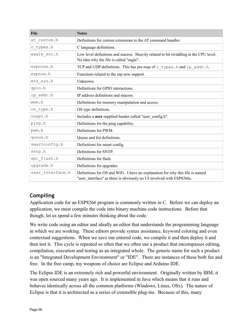
File Notes
at_custom.h Definitions for custom extensions to the AT command handler.
c_types.h C language definitions.
eagle_soc.h Low level definitions and macros. Heavily related to bit twiddling at the CPU level. No idea why the file is called "eagle".
espconn.h TCP and UDP definitions. This has pre-reqs of c_types.h and ip_addr.h.
espnow.h Functions related to the esp now support.
ets_sys.h Unknown.
gpio.h Definitions for GPIO interactions.
ip_addr.h IP address definitions and macros.
mem.h Definitions for memory manipulation and access.
os_type.h OS type definitions.
osapi.h Includes a user supplied header called "user_config.h".
ping.h Definitions for the ping capability.
pwm.h Definitions for PWM.
queue.h Queue and list definitions.
smartconfig.h Definitions for smart config.
sntp.h Definitions for SNTP.
spi_flash.h Definitions for flash.
upgrade.h Definitions for upgrades.
user_interface.h Definitions for OS and WiFi. I have no explanation for why this file is named "user_interface" as there is obviously no UI involved with ESP8266s.
CompilingApplication code for an ESP8266 program is commonly written in C. Before we can deploy an application, we must compile the code into binary machine code instructions. Before that though, let us spend a few minutes thinking about the code.
We write code using an editor and ideally an editor that understands the programming language in which we are working. These editors provide syntax assistance, keyword coloring and even contextual suggestions. When we save our entered code, we compile it and then deploy it and then test it. This cycle is repeated so often that we often use a product that encompasses editing, compilation, execution and testing as an integrated whole. The generic name for such a product is an "Integrated Development Environment" or "IDE". There are instances of these both fee andfree. In the free camp, my weapons of choice are Eclipse and Arduino IDE.
The Eclipse IDE is an extremely rich and powerful environment. Originally written by IBM, it was open sourced many years ago. It is implemented in Java which means that it runs and behaves identically across all the common platforms (Windows, Linux, OSx). The nature of Eclipse is that it is architected as a series of extensible plug-ins. Because of this, many
Page 56
contributors across many disciplines have extended the environment and it is now a cohesive framework for just about everything. Included in this mix is a set of plug-ins which, on aggregate, are called the "C Developers Tools" or "CDT". If one takes a bare bones Eclipse and adds the CDT, one now has a first rate C IDE. However, what the CDT does not supply (and for good reason) are the actual C compilers and associated tools themselves. Instead, one "defines" the tools that one wishes to use to the CDT and the CDT takes it from there.
For our ESP8266 story, this means that if we can find (which we can) a set of C compiler tools that take C source and generate Xtensa binary, we can use CDT to build our programs.
To make things more interesting though, we need to realize that C is not the only language we can use for building ESP8266 applications. We can also use C++ and assembly. You may be surprised that I mention assembly as that is as low level as we can possibly get however there areodd times when we need just that (thankfully rarely) … especially when we realize that we are pretty much programming directly to the metal. The Arduino libraries (for example) have at least one assembly language file.
For physical file types, the suffixes used for different file we will come across during development include:
• .h – C and C++ language header file
• .c – C language source file
• .cpp – C++ source file
• .S – Assembler source file
• .o – Object file (compiled source)
• .a – Archive library
To perform the compilations, we need a set of development tools.
My personal preference is the package for Eclipse which has everything pre-built and ready for use. However, these tools can also be downloaded from the Internet as open source projects on apiece by piece basis.
The macro LOCAL is a synonym for the C language keyword "static".
From reading the docs, no published example of how to compile was found. However, when oneuses the Eclipse open source project, one can see the Makefiles that are used and this exposes examples of compilation.
A typical compilation looks like:
17:57:16 **** Build of configuration Default for project k_blinky ****mingw32-make.exe -f C:/Users/IBM_ADMIN/Documents/RaspberryPi/ESP8266/EclipseDevKit/WorkSpace/k_blinky/Make
Page 57
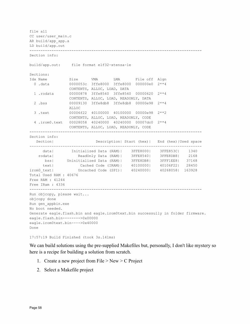
file all CC user/user_main.cAR build/app_app.aLD build/app.out------------------------------------------------------------------------------Section info:
build/app.out: file format elf32-xtensa-le
Sections:Idx Name Size VMA LMA File off Algn 0 .data 0000053c 3ffe8000 3ffe8000 000000e0 2**4 CONTENTS, ALLOC, LOAD, DATA 1 .rodata 00000878 3ffe8540 3ffe8540 00000620 2**4 CONTENTS, ALLOC, LOAD, READONLY, DATA 2 .bss 00009130 3ffe8db8 3ffe8db8 00000e98 2**4 ALLOC 3 .text 00006f22 40100000 40100000 00000e98 2**2 CONTENTS, ALLOC, LOAD, READONLY, CODE 4 .irom0.text 00028058 40240000 40240000 00007dc0 2**4 CONTENTS, ALLOC, LOAD, READONLY, CODE------------------------------------------------------------------------------Section info: Section| Description| Start (hex)| End (hex)|Used space------------------------------------------------------------------------------ data| Initialized Data (RAM)| 3FFE8000| 3FFE853C| 1340 rodata| ReadOnly Data (RAM)| 3FFE8540| 3FFE8DB8| 2168 bss| Uninitialized Data (RAM)| 3FFE8DB8| 3FFF1EE8| 37168 text| Cached Code (IRAM)| 40100000| 40106F22| 28450irom0_text| Uncached Code (SPI)| 40240000| 40268058| 163928Total Used RAM : 40676Free RAM : 41244Free IRam : 4336------------------------------------------------------------------------------Run objcopy, please wait...objcopy doneRun gen_appbin.exeNo boot needed.Generate eagle.flash.bin and eagle.irom0text.bin successully in folder firmware.eagle.flash.bin-------->0x00000eagle.irom0text.bin---->0x40000Done
17:57:19 Build Finished (took 3s.141ms)
We can build solutions using the pre-supplied Makefiles but, personally, I don't like mystery so here is a recipe for building a solution from scratch.
1. Create a new project from File > New > C Project
2. Select a Makefile project
Page 58
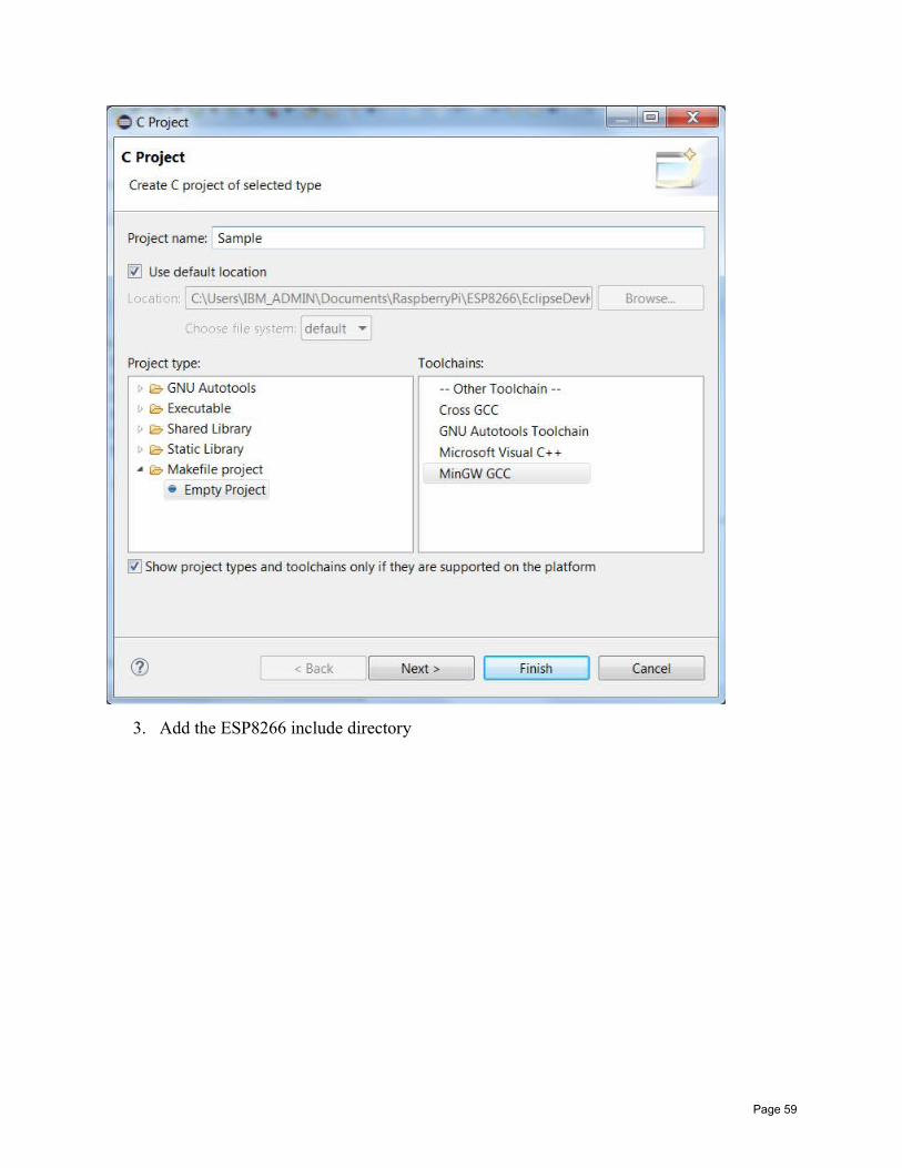
3. Add the ESP8266 include directory
Page 59
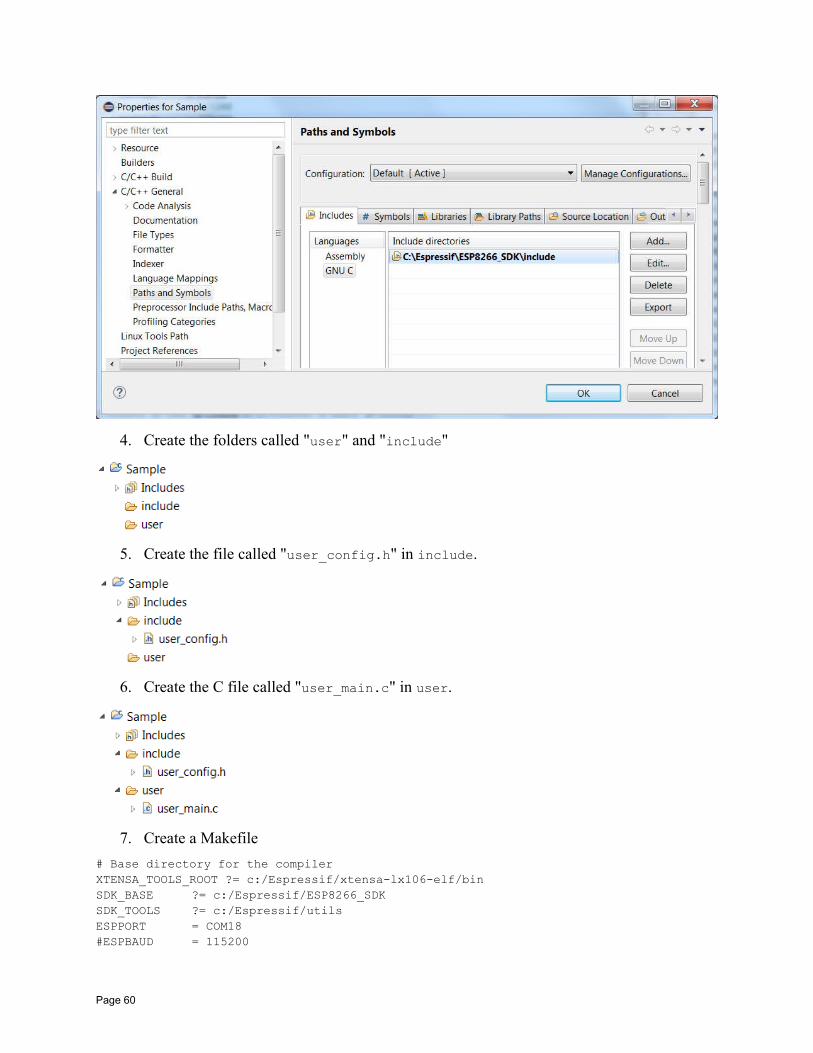
4. Create the folders called "user" and "include"
5. Create the file called "user_config.h" in include.
6. Create the C file called "user_main.c" in user.
7. Create a Makefile
# Base directory for the compilerXTENSA_TOOLS_ROOT ?= c:/Espressif/xtensa-lx106-elf/binSDK_BASE ?= c:/Espressif/ESP8266_SDKSDK_TOOLS ?= c:/Espressif/utilsESPPORT = COM18#ESPBAUD = 115200
Page 60
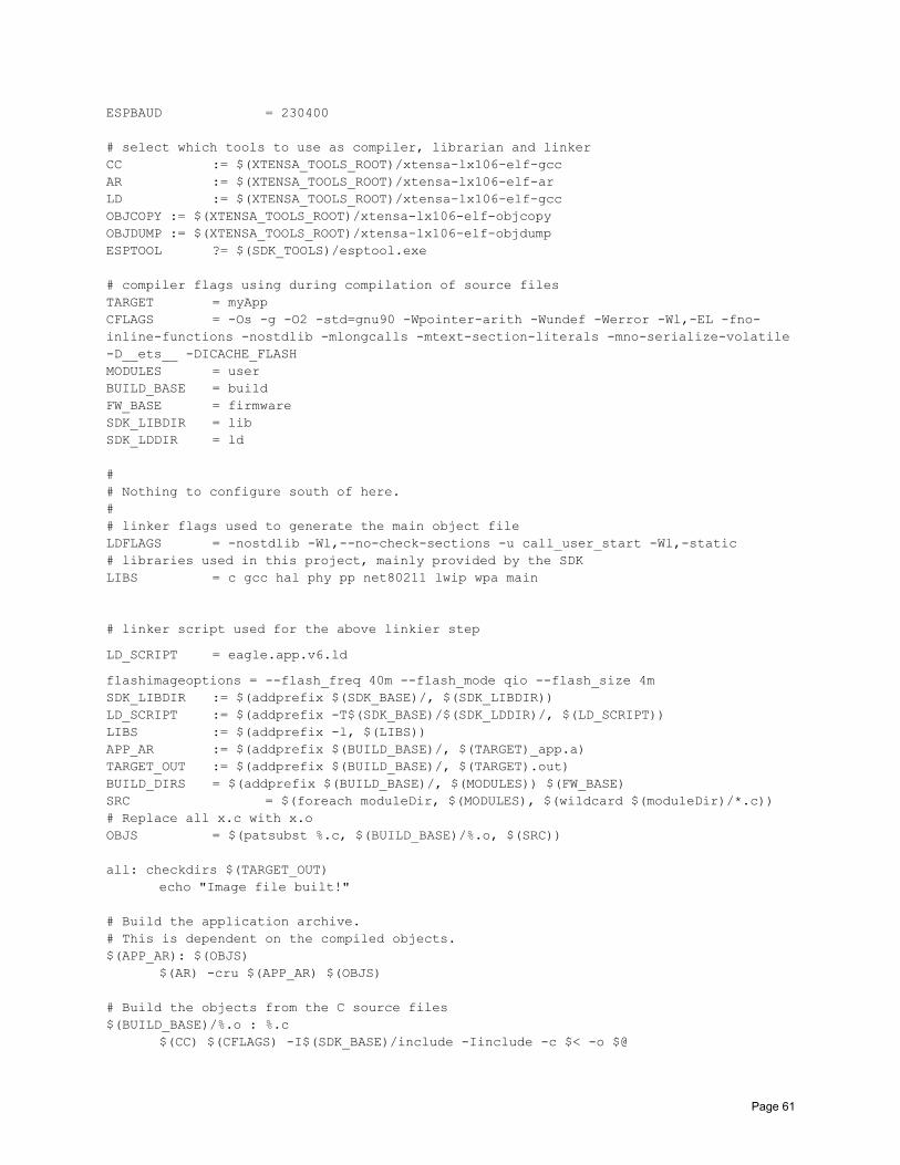
ESPBAUD = 230400
# select which tools to use as compiler, librarian and linkerCC := $(XTENSA_TOOLS_ROOT)/xtensa-lx106-elf-gccAR := $(XTENSA_TOOLS_ROOT)/xtensa-lx106-elf-arLD := $(XTENSA_TOOLS_ROOT)/xtensa-lx106-elf-gccOBJCOPY := $(XTENSA_TOOLS_ROOT)/xtensa-lx106-elf-objcopyOBJDUMP := $(XTENSA_TOOLS_ROOT)/xtensa-lx106-elf-objdumpESPTOOL ?= $(SDK_TOOLS)/esptool.exe
# compiler flags using during compilation of source filesTARGET = myAppCFLAGS = -Os -g -O2 -std=gnu90 -Wpointer-arith -Wundef -Werror -Wl,-EL -fno-inline-functions -nostdlib -mlongcalls -mtext-section-literals -mno-serialize-volatile-D__ets__ -DICACHE_FLASHMODULES = userBUILD_BASE = buildFW_BASE = firmwareSDK_LIBDIR = libSDK_LDDIR = ld
## Nothing to configure south of here.## linker flags used to generate the main object fileLDFLAGS = -nostdlib -Wl,--no-check-sections -u call_user_start -Wl,-static# libraries used in this project, mainly provided by the SDKLIBS = c gcc hal phy pp net80211 lwip wpa main
# linker script used for the above linkier step
LD_SCRIPT = eagle.app.v6.ld
flashimageoptions = --flash_freq 40m --flash_mode qio --flash_size 4mSDK_LIBDIR := $(addprefix $(SDK_BASE)/, $(SDK_LIBDIR))LD_SCRIPT := $(addprefix -T$(SDK_BASE)/$(SDK_LDDIR)/, $(LD_SCRIPT))LIBS := $(addprefix -l, $(LIBS))APP_AR := $(addprefix $(BUILD_BASE)/, $(TARGET)_app.a)TARGET_OUT := $(addprefix $(BUILD_BASE)/, $(TARGET).out)BUILD_DIRS = $(addprefix $(BUILD_BASE)/, $(MODULES)) $(FW_BASE)SRC = $(foreach moduleDir, $(MODULES), $(wildcard $(moduleDir)/*.c))# Replace all x.c with x.oOBJS = $(patsubst %.c, $(BUILD_BASE)/%.o, $(SRC))
all: checkdirs $(TARGET_OUT)echo "Image file built!"
# Build the application archive.# This is dependent on the compiled objects.$(APP_AR): $(OBJS)
$(AR) -cru $(APP_AR) $(OBJS)
# Build the objects from the C source files$(BUILD_BASE)/%.o : %.c
$(CC) $(CFLAGS) -I$(SDK_BASE)/include -Iinclude -c $< -o $@
Page 61
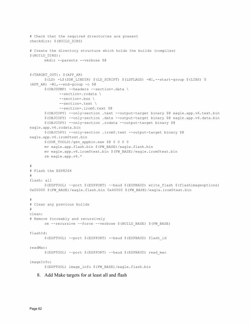
# Check that the required directories are presentcheckdirs: $(BUILD_DIRS)
# Create the directory structure which holds the builds (compiles)$(BUILD_DIRS):
mkdir --parents --verbose $@
$(TARGET_OUT): $(APP_AR)$(LD) -L$(SDK_LIBDIR) $(LD_SCRIPT) $(LDFLAGS) -Wl,--start-group $(LIBS) $
(APP_AR) -Wl,--end-group -o $@$(OBJDUMP) --headers --section=.data \
--section=.rodata \--section=.bss \--section=.text \--section=.irom0.text $@
$(OBJCOPY) --only-section .text --output-target binary $@ eagle.app.v6.text.bin$(OBJCOPY) --only-section .data --output-target binary $@ eagle.app.v6.data.bin$(OBJCOPY) --only-section .rodata --output-target binary $@
eagle.app.v6.rodata.bin$(OBJCOPY) --only-section .irom0.text --output-target binary $@
eagle.app.v6.irom0text.bin$(SDK_TOOLS)/gen_appbin.exe $@ 0 0 0 0mv eagle.app.flash.bin $(FW_BASE)/eagle.flash.binmv eagle.app.v6.irom0text.bin $(FW_BASE)/eagle.irom0text.binrm eagle.app.v6.*
## Flash the ESP8266# flash: all
$(ESPTOOL) --port $(ESPPORT) --baud $(ESPBAUD) write_flash $(flashimageoptions)0x00000 $(FW_BASE)/eagle.flash.bin 0x40000 $(FW_BASE)/eagle.irom0text.bin
## Clean any previous builds#clean:# Remove forceably and recursively
rm --recursive --force --verbose $(BUILD_BASE) $(FW_BASE)
flashId:$(ESPTOOL) --port $(ESPPORT) --baud $(ESPBAUD) flash_id
readMac:$(ESPTOOL) --port $(ESPPORT) --baud $(ESPBAUD) read_mac
imageInfo:$(ESPTOOL) image_info $(FW_BASE)/eagle.flash.bin
8. Add Make targets for at least all and flash
Page 62
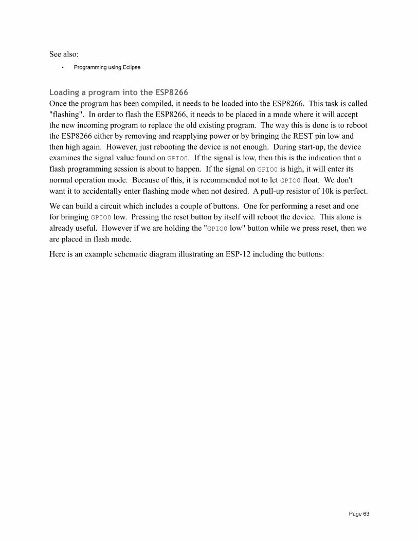
See also:
• Programming using Eclipse
Loading a program into the ESP8266Once the program has been compiled, it needs to be loaded into the ESP8266. This task is called"flashing". In order to flash the ESP8266, it needs to be placed in a mode where it will accept the new incoming program to replace the old existing program. The way this is done is to rebootthe ESP8266 either by removing and reapplying power or by bringing the REST pin low and then high again. However, just rebooting the device is not enough. During start-up, the device examines the signal value found on GPIO0. If the signal is low, then this is the indication that a flash programming session is about to happen. If the signal on GPIO0 is high, it will enter its normal operation mode. Because of this, it is recommended not to let GPIO0 float. We don't want it to accidentally enter flashing mode when not desired. A pull-up resistor of 10k is perfect.
We can build a circuit which includes a couple of buttons. One for performing a reset and one for bringing GPIO0 low. Pressing the reset button by itself will reboot the device. This alone is already useful. However if we are holding the "GPIO0 low" button while we press reset, then we are placed in flash mode.
Here is an example schematic diagram illustrating an ESP-12 including the buttons:
Page 63
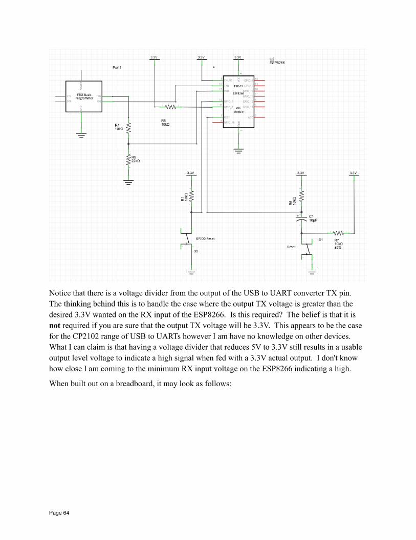
Notice that there is a voltage divider from the output of the USB to UART converter TX pin. The thinking behind this is to handle the case where the output TX voltage is greater than the desired 3.3V wanted on the RX input of the ESP8266. Is this required? The belief is that it is not required if you are sure that the output TX voltage will be 3.3V. This appears to be the case for the CP2102 range of USB to UARTs however I am have no knowledge on other devices. What I can claim is that having a voltage divider that reduces 5V to 3.3V still results in a usable output level voltage to indicate a high signal when fed with a 3.3V actual output. I don't know how close I am coming to the minimum RX input voltage on the ESP8266 indicating a high.
When built out on a breadboard, it may look as follows:
Page 64
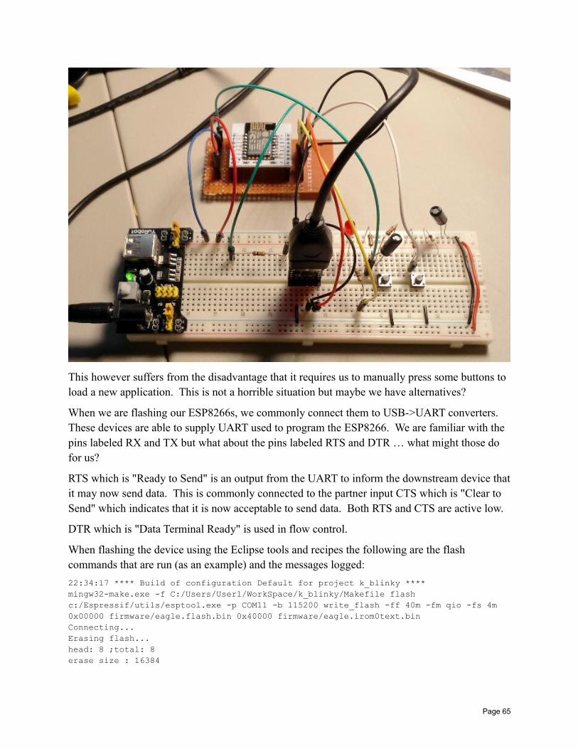
This however suffers from the disadvantage that it requires us to manually press some buttons to load a new application. This is not a horrible situation but maybe we have alternatives?
When we are flashing our ESP8266s, we commonly connect them to USB->UART converters. These devices are able to supply UART used to program the ESP8266. We are familiar with the pins labeled RX and TX but what about the pins labeled RTS and DTR … what might those do for us?
RTS which is "Ready to Send" is an output from the UART to inform the downstream device thatit may now send data. This is commonly connected to the partner input CTS which is "Clear to Send" which indicates that it is now acceptable to send data. Both RTS and CTS are active low.
DTR which is "Data Terminal Ready" is used in flow control.
When flashing the device using the Eclipse tools and recipes the following are the flash commands that are run (as an example) and the messages logged:
22:34:17 **** Build of configuration Default for project k_blinky ****mingw32-make.exe -f C:/Users/User1/WorkSpace/k_blinky/Makefile flash c:/Espressif/utils/esptool.exe -p COM11 -b 115200 write_flash -ff 40m -fm qio -fs 4m 0x00000 firmware/eagle.flash.bin 0x40000 firmware/eagle.irom0text.binConnecting...Erasing flash...head: 8 ;total: 8erase size : 16384
Page 65
Writing at 0x00000000... (3 %) Writing at 0x00000400... (6 %) …Writing at 0x00007000... (96 %) Writing at 0x00007400... (100 %) Written 30720 bytes in 3.01 seconds (81.62 kbit/s)...Erasing flash...head: 16 ;total: 41erase size : 102400
Writing at 0x00040000... (0 %) Writing at 0x00040400... (1 %) …Writing at 0x00067c00... (99 %) Writing at 0x00068000... (100 %) Written 164864 bytes in 16.18 seconds (81.53 kbit/s)...
Leaving...
22:34:40 Build Finished (took 23s.424ms)
As an example of what the messages look like if we fail to put the ESP8266 into flash mode, we have the following:
13:47:09 **** Build of configuration Default for project k_blinky ****mingw32-make.exe -f C:/Users/User1/WorkSpace/k_blinky/Makefile flash c:/Espressif/utils/esptool.exe -p COM11 -b 115200 write_flash -ff 40m -fm qio -fs 4m 0x00000 firmware/eagle.flash.bin 0x40000 firmware/eagle.irom0text.binConnecting…Traceback (most recent call last): File "esptool.py", line 558, in <module> File "esptool.py", line 160, in connectException: Failed to connectC:/Users/User1/WorkSpace/k_blinky/Makefile:313: recipe for target 'flash' failedmingw32-make.exe: *** [flash] Error 255
13:47:14 Build Finished (took 5s.329ms)
The tool called esptool.py provides an excellent environment for flashing the device but it can also be used for "reading" what is currently stored upon it. This can be used for making backups of the applications contained within before re-flashing them with a new program. This way, you can always return to what you had before over-writing. For example, on Unix:
esptool.py --port /dev/ttyUSB0 read_flash 0x00000 0xFFFF backup-0x00000.binesptool.py --port /dev/ttyUSB0 read_flash 0x10000 0x3FFFF backup-0x10000.bin
See also:
• USB to UART converters• Recommended setup for programming ESP8266• Working with memory• What is a UART?• esptool.py• esptool-ck
Page 66
Programming environmentsWe can program the ESP8266 using the Espressif supplied SDK on Windows using Eclipse. A separate chapter on setting up that environment is supplied. We also have the ability to program the ESP8266 using the Arduino IDE. This is potentially a game changing story and it too been given its own important chapter.
See also:
• Programming using Eclipse• Programming using the Arduino IDE
Compilation toolsThere are a number of tools that are essential when building C based ESP8266 applications.
arThe archive tool is used to packaged together compiled object files into libraries. These libraries end with ".a" (archive). A library can be named when using a linker and the objects contained within will be used to resolve externals.
Some of the most common flags used with this tool include:
• -c – Create a library
• -r – Replace existing members in the library
• -u – Update existing members in the library
The syntax of the command is:
ar -cru libraryName member.o member.o ….
See also:
• GNU – ar• nm
esptool.pyThis tool is an open source implementation used to flash the ESP8266 through a serial port. It is written in Python. Versions have been seen to be available as windows executables that appear to have been generated ".EXE" files from the Python code suitable for running on Windows without a supporting Python runtime installation.
• -p port | --port port – The serial port to use
• -b baud | --baud baud – The baud rate to use for serial
• -h – Help
• command -h – Help for that command
Page 67
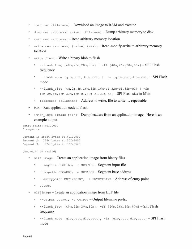
• load_ram filename – Download an image to RAM and execute
• dump_mem address size filename – Dump arbitrary memory to disk
• read_mem address – Read arbitrary memory location
• write_mem address value mask – Read-modify-write to arbitrary memory location
• write_flash – Write a binary blob to flash
--flash_freq 40m,26m,20m,80m | -ff 40m,26m,20m,80m – SPI Flash frequency
--flash_mode qio,qout,dio,dout | -fm qio,qout,dio,dout – SPI Flash mode
--flash_size 4m,2m,8m,16m,32m,16m-c1,32m-c1,32m-c2 | -fs
4m,2m,8m,16m,32m,16m-c1,32m-c1,32m-c2 – SPI Flash size in Mbit
address fileName – Address to write, file to write … repeatable
• run – Run application code in flash
• image_info image file – Dump headers from an application image. Here is an example output:
Entry point: 401000043 segments
Segment 1: 25356 bytes at 40100000Segment 2: 1344 bytes at 3ffe8000Segment 3: 924 bytes at 3ffe8540
Checksum: 40 (valid)
• make_image – Create an application image from binary files
--segfile SEGFILE, -f SEGFILE – Segment input file
--segaddr SEGADDR, -a SEGADDR – Segment base address
--entrypoint ENTRYPOINT, -e ENTRYPOINT – Address of entry point
output
• elf2image – Create an application image from ELF file
--output OUTPUT, -o OUTPUT – Output filename prefix
--flash_freq 40m,26m,20m,80m, -ff 40m,26m,20m,80m – SPI Flash frequency
--flash_mode qio,qout,dio,dout, -fm qio,qout,dio,dout – SPI Flash mode
Page 68
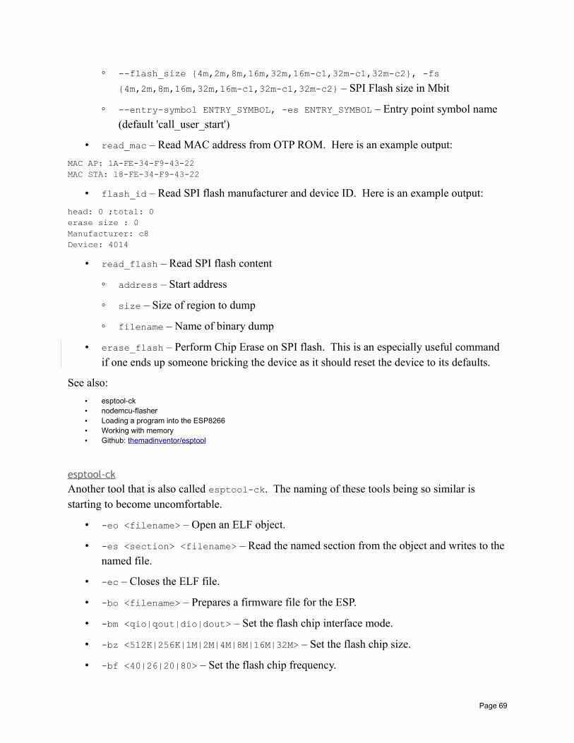
--flash_size 4m,2m,8m,16m,32m,16m-c1,32m-c1,32m-c2, -fs
4m,2m,8m,16m,32m,16m-c1,32m-c1,32m-c2 – SPI Flash size in Mbit
--entry-symbol ENTRY_SYMBOL, -es ENTRY_SYMBOL – Entry point symbol name (default 'call_user_start')
• read_mac – Read MAC address from OTP ROM. Here is an example output:
MAC AP: 1A-FE-34-F9-43-22MAC STA: 18-FE-34-F9-43-22
• flash_id – Read SPI flash manufacturer and device ID. Here is an example output:
head: 0 ;total: 0erase size : 0Manufacturer: c8Device: 4014
• read_flash – Read SPI flash content
address – Start address
size – Size of region to dump
filename – Name of binary dump
• erase_flash – Perform Chip Erase on SPI flash. This is an especially useful command if one ends up someone bricking the device as it should reset the device to its defaults.
See also:
• esptool-ck• nodemcu-flasher• Loading a program into the ESP8266• Working with memory• Github: themadinventor/esptool
esptool-ckAnother tool that is also called esptool-ck. The naming of these tools being so similar is starting to become uncomfortable.
• -eo <filename> – Open an ELF object.
• -es <section> <filename> – Read the named section from the object and writes to thenamed file.
• -ec – Closes the ELF file.
• -bo <filename> – Prepares a firmware file for the ESP.
• -bm <qio|qout|dio|dout> – Set the flash chip interface mode.
• -bz <512K|256K|1M|2M|4M|8M|16M|32M> – Set the flash chip size.
• -bf <40|26|20|80> – Set the flash chip frequency.
Page 69
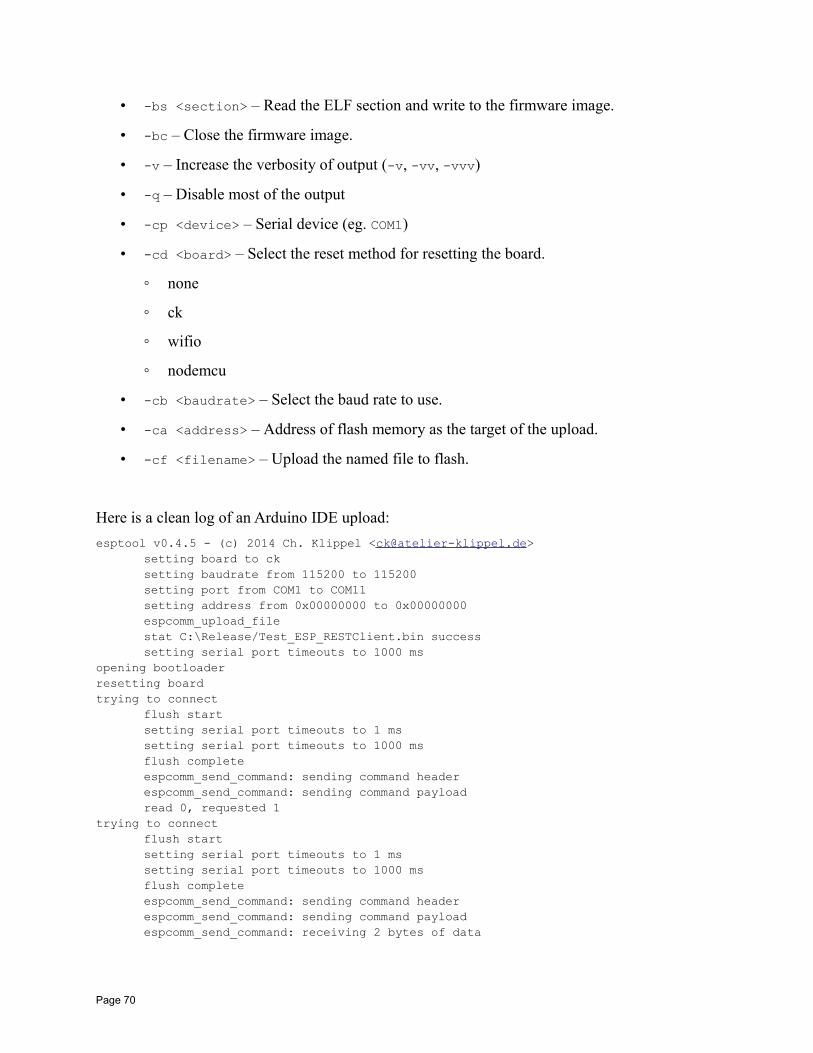
• -bs <section> – Read the ELF section and write to the firmware image.
• -bc – Close the firmware image.
• -v – Increase the verbosity of output (-v, -vv, -vvv)
• -q – Disable most of the output
• -cp <device> – Serial device (eg. COM1)
• -cd <board> – Select the reset method for resetting the board.
none
ck
wifio
nodemcu
• -cb <baudrate> – Select the baud rate to use.
• -ca <address> – Address of flash memory as the target of the upload.
• -cf <filename> – Upload the named file to flash.
Here is a clean log of an Arduino IDE upload:
esptool v0.4.5 - (c) 2014 Ch. Klippel <[email protected]>setting board to cksetting baudrate from 115200 to 115200setting port from COM1 to COM11setting address from 0x00000000 to 0x00000000espcomm_upload_filestat C:\Release/Test_ESP_RESTClient.bin successsetting serial port timeouts to 1000 ms
opening bootloaderresetting boardtrying to connect
flush startsetting serial port timeouts to 1 mssetting serial port timeouts to 1000 msflush completeespcomm_send_command: sending command headerespcomm_send_command: sending command payloadread 0, requested 1
trying to connectflush startsetting serial port timeouts to 1 mssetting serial port timeouts to 1000 msflush completeespcomm_send_command: sending command headerespcomm_send_command: sending command payloadespcomm_send_command: receiving 2 bytes of data
Page 70
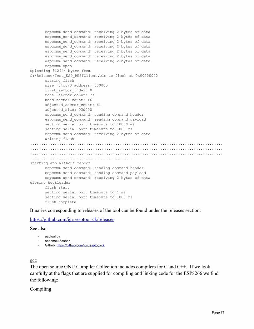
espcomm_send_command: receiving 2 bytes of dataespcomm_send_command: receiving 2 bytes of dataespcomm_send_command: receiving 2 bytes of dataespcomm_send_command: receiving 2 bytes of dataespcomm_send_command: receiving 2 bytes of dataespcomm_send_command: receiving 2 bytes of dataespcomm_send_command: receiving 2 bytes of dataespcomm_open
Uploading 312944 bytes fromC:\Release/Test_ESP_RESTClient.bin to flash at 0x00000000
erasing flashsize: 04c670 address: 000000first_sector_index: 0total_sector_count: 77head_sector_count: 16adjusted_sector_count: 61adjusted_size: 03d000espcomm_send_command: sending command headerespcomm_send_command: sending command payloadsetting serial port timeouts to 10000 mssetting serial port timeouts to 1000 msespcomm_send_command: receiving 2 bytes of datawriting flash
......................................................................................
......................................................................................
......................................................................................
.............................................…starting app without reboot
espcomm_send_command: sending command headerespcomm_send_command: sending command payloadespcomm_send_command: receiving 2 bytes of data
closing bootloaderflush startsetting serial port timeouts to 1 mssetting serial port timeouts to 1000 msflush complete
Binaries corresponding to releases of the tool can be found under the releases section:
https://github.com/igrr/esptool-ck/releases
See also:
• esptool.py• nodemcu-flasher• Github: https://github.com/igrr/esptool-ck
gccThe open source GNU Compiler Collection includes compilers for C and C++. If we look carefully at the flags that are supplied for compiling and linking code for the ESP8266 we find the following:
Compiling
Page 71
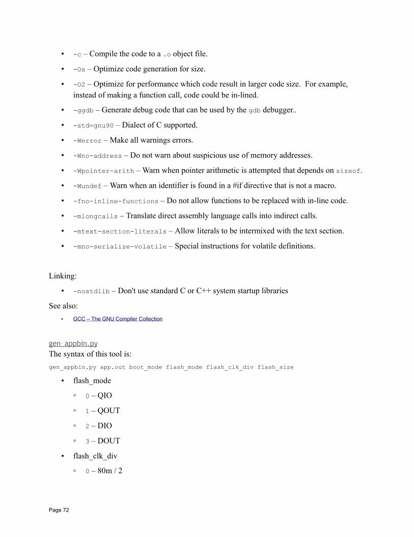
• -c – Compile the code to a .o object file.
• -Os – Optimize code generation for size.
• -O2 – Optimize for performance which code result in larger code size. For example, instead of making a function call, code could be in-lined.
• -ggdb – Generate debug code that can be used by the gdb debugger..
• -std=gnu90 – Dialect of C supported.
• -Werror – Make all warnings errors.
• -Wno-address – Do not warn about suspicious use of memory addresses.
• -Wpointer-arith – Warn when pointer arithmetic is attempted that depends on sizeof.
• -Wundef – Warn when an identifier is found in a #if directive that is not a macro.
• -fno-inline-functions – Do not allow functions to be replaced with in-line code.
• -mlongcalls – Translate direct assembly language calls into indirect calls.
• -mtext-section-literals – Allow literals to be intermixed with the text section.
• -mno-serialize-volatile – Special instructions for volatile definitions.
Linking:
• -nostdlib – Don't use standard C or C++ system startup libraries
See also:
• GCC – The GNU Compiler Collection
gen_appbin.pyThe syntax of this tool is:
gen_appbin.py app.out boot_mode flash_mode flash_clk_div flash_size
• flash_mode
0 – QIO
1 – QOUT
2 – DIO
3 – DOUT
• flash_clk_div
0 – 80m / 2
Page 72

1 – 80m / 3
2 – 80m / 4
0xf – 80m / 1
• flash_size_map
0 – 512 KB (256 KB + 256 KB)
1 – 256 KB
2 – 1024 KB (512 KB + 512 KB)
3 – 2048 KB (512 KB + 512 KB)
4 – 4096 KB (512 KB + 512 KB)
5 – 2048 KB (1024 KB + 1024 KB)
6 – 4096 KB (1024 KB + 1024 KB)
The following files are expected to exist:
• eagle.app.v6.irom0text.bin
• eagle.app.v6.text.bin
• eagle.app.v6.data.bin
• eagle.app.v6.rodata.bin
The output of this command is a new file called eagle.app.flash.bin.
makeMake is a compilation engine used to track what has to be compiled in order to build your target application. Make is driven by a Makefile. Although powerful and simple enough for simple C projects, it can get complex pretty quickly. If you find yourself studying Makefiles written by others, grab the excellent GNU make documentation and study it deeply.
nodemcu-flasherThis tool is another instance of an ESP8266 flasher. Unlike some of the other tools available, this one is GUI based. From within the tool one can select all the options that one might expect including one or more files to flash, the serial connection and information and more.
One entered, one can click the "Flash" button and flashing begins with an attractive progress bar.
The following is what the tool looks like after completing a flash:
Page 73
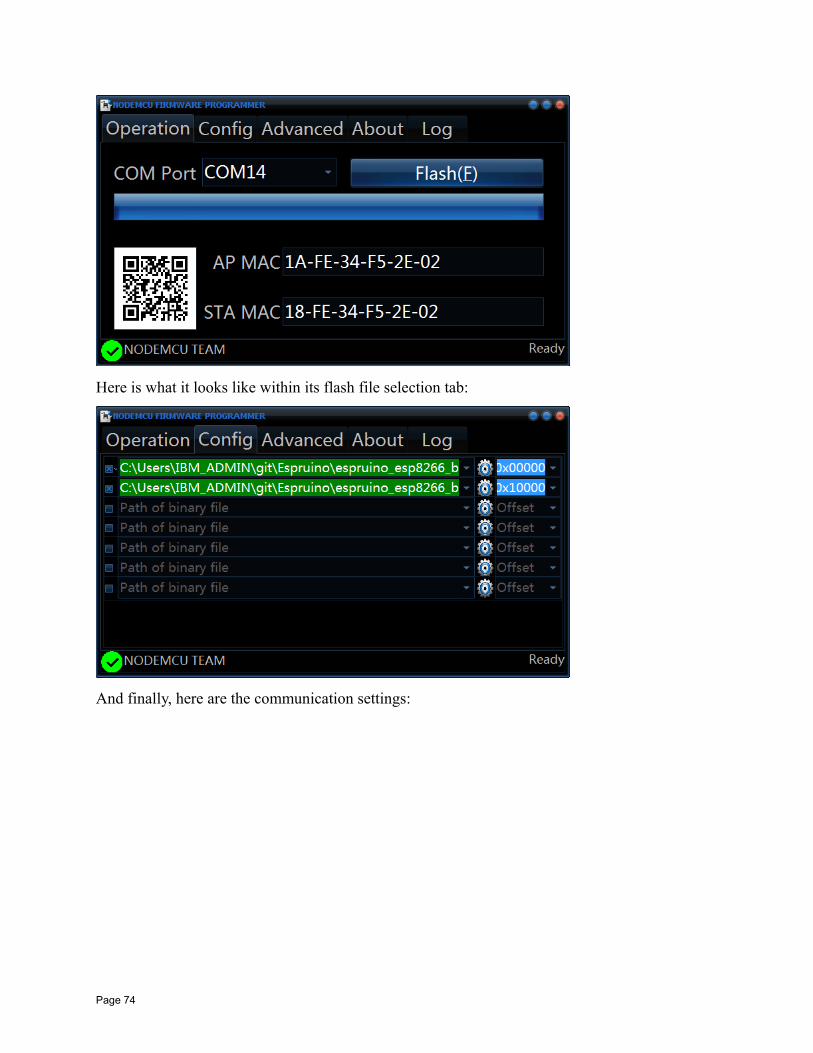
Here is what it looks like within its flash file selection tab:
And finally, here are the communication settings:
Page 74
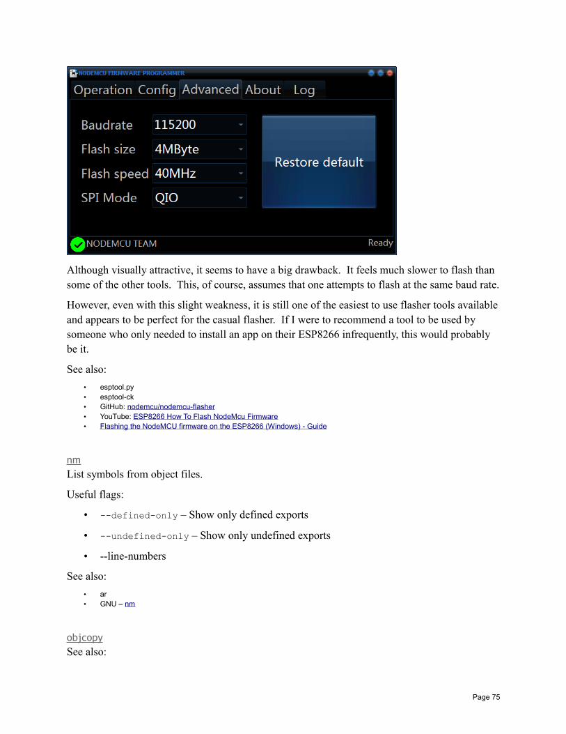
Although visually attractive, it seems to have a big drawback. It feels much slower to flash than some of the other tools. This, of course, assumes that one attempts to flash at the same baud rate.
However, even with this slight weakness, it is still one of the easiest to use flasher tools availableand appears to be perfect for the casual flasher. If I were to recommend a tool to be used by someone who only needed to install an app on their ESP8266 infrequently, this would probably be it.
See also:
• esptool.py• esptool-ck• GitHub: nodemcu/nodemcu-flasher• YouTube: ESP8266 How To Flash NodeMcu Firmware• Flashing the NodeMCU firmware on the ESP8266 (Windows) - Guide
nmList symbols from object files.
Useful flags:
• --defined-only – Show only defined exports
• --undefined-only – Show only undefined exports
• --line-numbers
See also:
• ar• GNU – nm
objcopySee also:
Page 75
• GNU – objcopy
objdumpThe command is xtensa-lx106-elf-objdump located in
C:\Espressif\xtensa-lx106-elf\bin.
• Wikipedia – objdump• GNU – objdump• man page – objdump(1)
xxdThis is a deceptively simple but useful tool. What it does is dump binary data contained within afile in a formatted form. One powerful use of it is to take a binary file and produce a C language data structure that represents the content of the file. This means that you can take binary data and include it in your applications. A copy of xxd.exe is distributed with the SDK supplied by Espressif in the tools folder.
The following will read the content of inFile as binary data and produce a header file in the outFile.
xxd -include <inFile> <outFile>
LinkingWhen the C and C++ source files that constitute your project have been compiled to their object files, it is time to link them with libraries to finalize the executable to be deployed. Here is an example of a linking command used to build an executable.
xtensa-lx106-elf-gcc-g-Os-nostdlib-Wl,--no-check-sections -u call_user_start-Wl,-static
"-L??/tools/sdk//lib""-L??tools/sdk//ld""-Teagle.flash.512k.ld"
-Wl,-wrap,system_restart_local-Wl,-wrap,register_chipv6_phy -o "Release/Test_ESP_RESTClient.elf"-Wl,--start-group x.oy.oz.o-lm-lgcc-lhal-lphy
Page 76
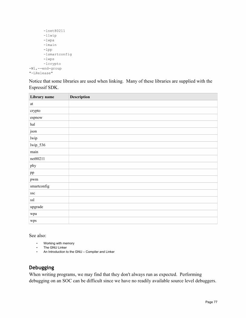
-lnet80211-llwip-lwpa-lmain-lpp-lsmartconfig-lwps-lcrypto
-Wl,--end-group "-LRelease"
Notice that some libraries are used when linking. Many of these libraries are supplied with the Espressif SDK.
Library name Description
at
crypto
espnow
hal
json
lwip
lwip_536
main
net80211
phy
pp
pwm
smartconfig
ssc
ssl
upgrade
wpa
wps
See also:
• Working with memory• The GNU Linker• An Introduction to the GNU – Compiler and Linker
DebuggingWhen writing programs, we may find that they don't always run as expected. Performing debugging on an SOC can be difficult since we have no readily available source level debuggers.
Page 77
Logging to UART1We can insert diagnostic statements using os_printf(). This causes the text and data associatedwith these functions to be written to UART1 (GPIO 2). If we attach a USB → UART device in the circuit, we can then look at the data logged. In my development environment I always have two USB → UART devices in play. One to flash new applications and one to use for diagnostic output.
The OS is also able to write debugging information. By default this is on but can be switched offwith a call to system_set_os_print().
See also:
• USB to UART converters• Working with serial• system_set_os_print
Run a BlinkyPhysically looking at an ESP8266 there isn't much to see that tells you all is working well within it. There is a power light and a network transmission active light … but that's about it. A technique that I recommend is to always have your device perform execute a "blinking led" which is commonly known as a "Blinky". This can be achieved by connecting a GPIO pin to a current limiting resistor and then to an LED. When the GPIO signal goes high, the LED lights. When the GPIO signal goes low, the LED becomes dark. If we define a timer callback that is called (for example) once a second and toggles the GPIO pin signal value each invocation, we will have a simple blinking LED. You will be surprised how good a feeling it will give simply knowing that something is alive within the device each time you see it blink.
The cost of running the timer and changing the I/O value to achieve a blinking should not be a problem during development time so I wouldn't worry about side effects of doing this. Obviously for a published application, you may not desire this and can simply remove it.
However, although this is a trivial circuit, it has a lot of uses during development. First, you will always know that the device is operating. If the LED is blinking, you know the device has powerand logic processing control. If the light stops blinking, you will know that something has locked up or you have entered an infinite loop.
Another useful purpose for including the Blinky is to validate that you have entered flash mode when programming the device. If we understand that the device can boot up in normal or flash mode and we boot it up in flash mode, then the Blinky will stop executing. This can be useful if you are using buttons or jumpers to toggle the boot mode as it will provide evidence that you are not in normal mode. On occasion I have mis-pressed some control buttons and was quickly able to realize that something was wrong before even attempting to flash it as the Blinky was still going.
Page 78
Here is some simple code for setting up a Blinky. In this example we use GPIO4 as the LED driver. First, the code we place in user_init:
PIN_FUNC_SELECT(PERIPHS_IO_MUX_GPIO4_U, FUNC_GPIO4);os_timer_disarm(&blink_timer);os_timer_setfn(&blink_timer, (os_timer_func_t *)blink_cb, (void *)0);os_timer_arm(&blink_timer, 1000, 1);
This assumes a global called blink_timer defined as:
LOCAL os_timer_t blink_timer;
The callback function in this example is called blink_cb and looks like:
LOCAL void ICACHE_FLASH_ATTR blink_cb(void *arg)
led_state = !led_state;GPIO_OUTPUT_SET(4, led_state);
The global variable called led_state contains the current state of the LED (1=on, 0=off):
LOCAL uint8_t led_state=0;
Dumping IP AddressesBeing a WiFi and TCP/IP device, you would imagine that the ESP8266 works a lot with IP addresses and you would be right. We can generate a string representation of an IP address using:
os_printf(IPSTR, IP2STR(pIpAddrVar))
the IPSTR macro is "%d.%d.%d.%d" so the above is equivalent to:
os_printf("%d.%d.%d.%d", IP2STR(pIpAddrVar))
which may be more useful in certain situations.
See also:
• ipaddr_t
Exception handlingAt runtime, things may not always work as expected and an exception can be thrown. For example, you might attempt to access storage at an invalid location or write to read only memoryor perform a divide by zero.
When such an occurrence happens, the device will reboot itself but not before writing some diagnostics to UART1. Diagnostics may look like:
Fatal exception (28):epc1=0x40243182, epc2=0x00000000, epc3=0x00000000, excvaddr=0x00000050, depc=0x00000000
The codes are as follows:
Page 79
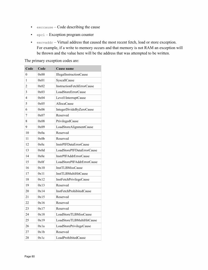
• exccause – Code describing the cause
• epc1 – Exception program counter
• excvaddr – Virtual address that caused the most recent fetch, load or store exception. For example, if a write to memory occurs and that memory is not RAM an exception will be thrown and the value here will be the address that was attempted to be written.
The primary exception codes are:
Code Code Cause name
0 0x00 IllegalInstructionCause
1 0x01 SyscallCause
2 0x02 InstructionFetchErrorCause
3 0x03 LoadStoreErrorCause
4 0x04 Level1InterruptCause
5 0x05 AllocaCause
6 0x06 IntegerDivideByZeroCause
7 0x07 Reserved
8 0x08 PrivilegedCause
9 0x09 LoadStoreAlignmentCause
10 0x0a Reserved
11 0x0b Reserved
12 0x0c InstrPIFDataErrorCause
13 0x0d LoadStorePIFDataErrorCause
14 0x0e InstrPIFAddrErrorCause
15 0x0f LoadStorePIFAddrErrorCause
16 0x10 InstTLBMissCause
17 0x11 InstTLBMultiHitCause
18 0x12 InstFetchPrivilegeCause
19 0x13 Reserved
20 0x14 InstFetchProhibitedCause
21 0x15 Reserved
22 0x16 Reserved
23 0x17 Reserved
24 0x18 LoadStoreTLBMissCause
25 0x19 LoadStoreTLBMultiHitCause
26 0x1a LoadStorePrivilegeCause
27 0x1b Reserved
28 0x1c LoadProhibitedCause
Page 80
29 0x1d StoreProhibitedCause
30 0x1e Reserved
31 0x1f Reserved
32-39 0x20-0x27 CoprocessornDisabled
40-63 0x28-0x3f Reserved
If we know the location of the exception, we can analyze the executable (app.out) to figure out what piece of code caused the problem. For example:
xtensa-lx106-elf-objdump -x app.out -d
See also:
• system_get_rst_info• struct rst_info
Using a debugger (GDB)GDB is the GNU Debugger and is an excellent tool for debugging compiled C source code. However, it is primarily designed to debug OS hosted applications such as those compiled for Windows or Linux and didn't have much applicability to the ESP8266. This was until Espressif released their GDB stub.
The version of the debugger must be the xtensa-lx106-elf-gdb tool.
See also:
• Github: espressif/esp-gdbstub
Debugging and testing TCP and UDP connectionsWhen working with TCP/IP, you will likely want to have some applications that you can use to send and receive data so that you can be sure the ESP8266 is working. There are a number of excellent tools and utilities available and these vary by platform and function.
Android – Socket ProtocolThe Socket Protocol is a free Android app available from the Google play app store. See:
https://play.google.com/store/apps/details?id=aprisco.app.android
Android – UDP Sender/ReceiverThe UDP Sender/Receiver is another free Android app available from the Google play app store. What makes this one interesting is its ability to be a UDP (as opposed to TCP) sender and receiver. See:
https://play.google.com/store/apps/details?id=com.jca.udpsendreceive
Page 81
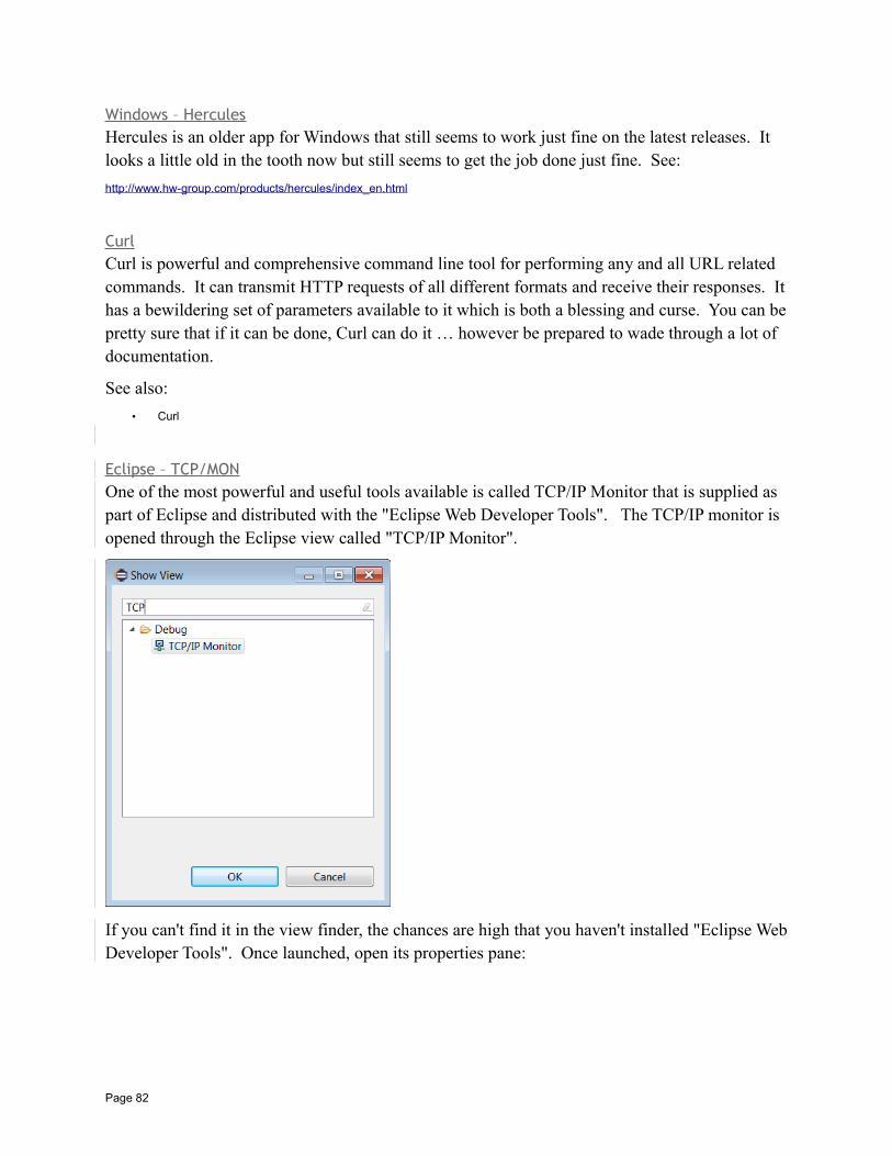
Windows – HerculesHercules is an older app for Windows that still seems to work just fine on the latest releases. It looks a little old in the tooth now but still seems to get the job done just fine. See:
http://www.hw-group.com/products/hercules/index_en.html
CurlCurl is powerful and comprehensive command line tool for performing any and all URL related commands. It can transmit HTTP requests of all different formats and receive their responses. Ithas a bewildering set of parameters available to it which is both a blessing and curse. You can bepretty sure that if it can be done, Curl can do it … however be prepared to wade through a lot of documentation.
See also:
• Curl
Eclipse – TCP/MONOne of the most powerful and useful tools available is called TCP/IP Monitor that is supplied as part of Eclipse and distributed with the "Eclipse Web Developer Tools". The TCP/IP monitor is opened through the Eclipse view called "TCP/IP Monitor".
If you can't find it in the view finder, the chances are high that you haven't installed "Eclipse WebDeveloper Tools". Once launched, open its properties pane:
Page 82
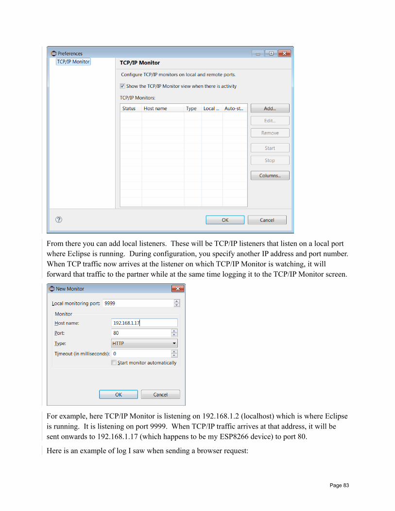
From there you can add local listeners. These will be TCP/IP listeners that listen on a local port where Eclipse is running. During configuration, you specify another IP address and port number.When TCP traffic now arrives at the listener on which TCP/IP Monitor is watching, it will forward that traffic to the partner while at the same time logging it to the TCP/IP Monitor screen.
For example, here TCP/IP Monitor is listening on 192.168.1.2 (localhost) which is where Eclipseis running. It is listening on port 9999. When TCP/IP traffic arrives at that address, it will be sent onwards to 192.168.1.17 (which happens to be my ESP8266 device) to port 80.
Here is an example of log I saw when sending a browser request:
Page 83
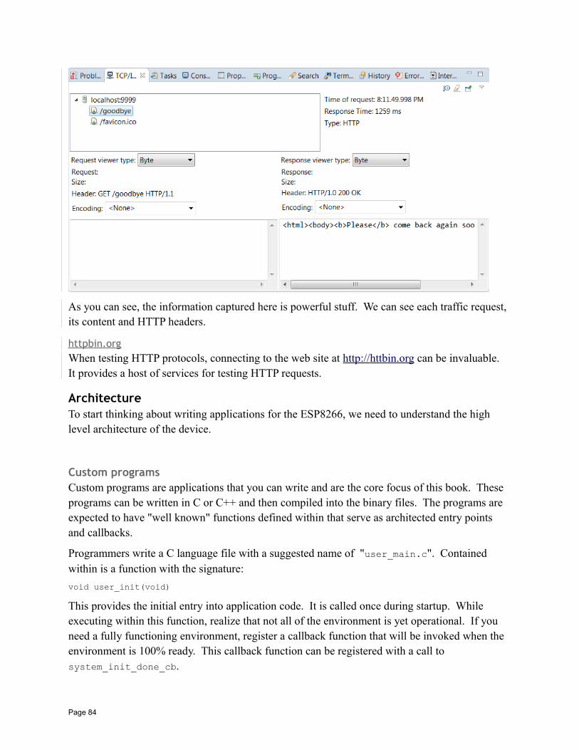
As you can see, the information captured here is powerful stuff. We can see each traffic request, its content and HTTP headers.
httpbin.orgWhen testing HTTP protocols, connecting to the web site at http:// httbin.org can be invaluable. It provides a host of services for testing HTTP requests.
ArchitectureTo start thinking about writing applications for the ESP8266, we need to understand the high level architecture of the device.
Custom programsCustom programs are applications that you can write and are the core focus of this book. These programs can be written in C or C++ and then compiled into the binary files. The programs are expected to have "well known" functions defined within that serve as architected entry points and callbacks.
Programmers write a C language file with a suggested name of "user_main.c". Contained within is a function with the signature:
void user_init(void)
This provides the initial entry into application code. It is called once during startup. While executing within this function, realize that not all of the environment is yet operational. If you need a fully functioning environment, register a callback function that will be invoked when the environment is 100% ready. This callback function can be registered with a call to system_init_done_cb.
Page 84
RF initialization must also be provided via:
void user_rf_pre_init(void)
When running in user code, we need to be sensitive that the primary purpose of the device is network communications. Since these are handled in the software, when user code gets control, that simply means that networking code doesn't. Since we only have one thread of control, we can't be in two places at once. The recommended duration to spend in user code at a single sitting is less than 10msecs.
See also:
• system_init_done_cb
WiFi at startupThe ESP8266 stores WiFi start-up information in flash memory. This allows it to perform its functions at start-up without having to ask the user for any special information. In my opinion, this is more trouble than it is worth. If I am going to write an ESP8266 application, I want to control when, how and to what it will connect or be an access point. Thankfully, there is a function called wifi_station_set_auto_connect() and its partner called wifi_station_get_auto_connect(). These allow us to override the auto connection functionswhen we are a station.
See also:
• wifi_station_get_auto_connect• wifi_station_set_auto_connect
Working with WiFiThe ESP8266 can either be a station in the network, an access point for other devices or both. This is a fundamental consideration and we will want to choose how the device behaves early on in our design. Once we have chosen what we want, we set a global mode property which indicates which of the operational modes our device will perform (station, access point or station AND access point).
See also:
• wifi_set_opmode• wifi_set_opmode_current
Scanning for access pointsIf the ESP8266 is performing the role of a station we will need to connect to an access point. Wecan request a list of the available access points against which we can attempt to connect. We do this using the wifi_station_scan() function. This function takes a callback function pointer as one of its parameters. This callback will be invoked when the scan has completed. The
Page 85
callback is necessary because it can take some time (a few seconds) for the scan to be performed and we can't afford to block operation of the system as a whole until complete. The scan callback function receives a linked list of BSS structures. Contained within a BSS structure are:
• The SSID for the network
• The BSSID for the access point
• The channel
• The signal strength
• … others
For example:
void scanCB(void *arg, STATUS status) struct bss_info *bssInfo;bssInfo = (struct bss_info *)arg;// skip the first in the chain … it is invalidbssInfo = STAILQ_NEXT(bssInfo, next);while(bssInfo != NULL)
os_printf("ssid: %s\n", bssInfo->ssid);bssInfo = STAILQ_NEXT(bssInfo, next);
//...
// Ensure we are in station modewifi_set_opmode_current(STATION_MODE);
// Request a scan of the network calling "scanCB" on completionwifi_station_scan(NULL, scanCB);
Note the use of the STAILQ_NEXT() macro to navigate to the next entry in the list. The end of the list is indicated when this returns NULL.
See also:
• Sample – WiFi Scanner• wifi_station_scan• wifi_set_opmode• struct bss_info• STATUS
Defining the operating modeThe ESP8266 can execute as a WiFi Station, a WiFi access point or both a station and an access point. These are considered the three possible global operating modes. The operating mode that is used when the device boots is retained in flash memory but can be changed with a call to wifi_set_opmode(). This will change the current mode as well as record the mode to be used on next restart. To merely change the mode without changing the next boot mode, we can use
Page 86
wifi_set_opmode_current(). To retrieve the current mode, we can use wifi_get_opmode() and to retrieve the mode used on boot, we can use wifi_get_opmode_default(). Quite why we have the option to change the current mode without saving it in flash memory is a mystery. Presumably there is some occasion when such a feature was needed and thus exposed but what ever that reason may be is not obvious.
See also:
• wifi_get_opmode• wifi_get_opmode_default• wifi_set_opmode• wifi_set_opmode_current
Handling WiFi eventsDuring the course of operating as a WiFi device, certain events may occur that ESP8266 needs toknow about. These may be of importance or interest to the applications running within it. Since we don't know when, or even if, any events will happen, we can't have our application block waiting for them to occur. Instead what we should do is define a callback function that will be invoked should an event actually occur. The function called wifi_set_event_handler_cb() does just that. It registers a function that will be called when the ESP8266 detects certain types of WiFi related events. The registered function is invoked and passed a rich data structure that includes the type of event and associated data corresponding to that event. The types of events that cause the callback to occur are:
• We connected to an access point
• We disconnected from an access point
• The authorization mode changed
• We got a DHCP issued IP address
• A station connected to us when we are in Access Point mode
• A station disconnected from us when we are in Access Point mode
Here is an example of an event handler function that simply logs the name of the event that was seen:
void eventHandler(System_Event_t *event) switch(event->event) case EVENT_STAMODE_CONNECTED:
os_printf("Event: EVENT_STAMODE_CONNECTED");break;
case EVENT_STAMODE_DISCONNECTED:os_printf("Event: EVENT_STAMODE_DISCONNECTED");break;
case EVENT_STAMODE_AUTHMODE_CHANGE:os_printf("Event: EVENT_STAMODE_AUTHMODE_CHANGE");break;
case EVENT_STAMODE_GOT_IP:
Page 87
os_printf("Event: EVENT_STAMODE_GOT_IP");break;
case EVENT_SOFTAPMODE_STACONNECTED:os_printf("Event: EVENT_SOFTAPMODE_STACONNECTED");break;
case EVENT_SOFTAPMODE_STADISCONNECTED:os_printf("Event: EVENT_SOFTAPMODE_STADISCONNECTED");break;
default:os_printf("Unexpected event: %d\r\n", event->event);break;
The callback function can be registered in user_init() as follows:
wifi_set_event_handler_cb(eventHandler);
We are limited to what we should do in an event handler callback. Specifically, it appears that we should not try and form new connections. Instead, we should post a task that we are now able to do additional work.
See also:
• wifi_set_event_handle_cb• System_Event_t
Station configurationWhen we think of an ESP8266 as a WiFi Station, we will realize that at any one time, it can only be connected to one access point. Putting it another way, there is no meaning in saying that the device is connected to two or more access points at the same time.
The identity of the access point to which we wish to be associated is known as the "station_config" and is modeled as the C structure called "struct station_config". Contained within that structure are two very important fields called "ssid" and "password". The ssid field is the SSID of the access point to which we will connect. The password field is the clear text value of the password that will be used to authenticate our device to the target access point to allow connection.
When booted, the ESP8266 remembers the last station_config we set. We can explicitly set the station_config data using the function wifi_station_set_config(). This will set the current configuration and save it for later retrieval after a reboot. If we only wish to set the current station config and not have the information persisted, we can use the wifi_station_set_config_current().
We should not try and perform any WiFi operations until the device is fully initialized. We knowwe are initialized by registering a callback using the system_init_done_cb() function.
For example:
Page 88
void initDone() wifi_set_opmode_current(STATION_MODE);struct station_config stationConfig;strncpy(stationConfig.ssid, "myssid", 32);strncpy(stationConfig.password, "mypassword", 64);wifi_station_set_config(&stationConfig);
See also:
• system_init_done_cb• wifi_station_get_config• wifi_station_get_config_default• wifi_station_set_config• wifi_station_set_config_current• wifi_set_opmode_current• station_config
Connecting to an access pointOnce the ESP8266 has been set up with the station configuration details which includes the SSIDand password, we are ready to perform a connection to the target access point. The function wifi_station_connect() will form the connection. Realize that this is not instantaneous and you should not assume that immediately following this command you are connected. Nothing in the ESP8266 blocks and as such neither does the call to this function. Some time later, we will actually be connected. We will see two callback events fired. The first is EVENT_STAMODE_CONNECTED indicating that we have connected to the access point. The second event is EVENT_STAMODE_GOT_IP which indicates that we have been assigned an IP address by the DHCP server. Only at that point can we truly participate in communications. If we are usingstatic IP addresses for our device, then we will only see the connected event.
There is one further consideration associated with connecting to access points and that is the ideaof automatic connection. There is a boolean flag that is stored in flash that indicates whether or not the ESP8266 should attempt to automatically connect to the last used access point. If set to true, then after the device is started and without you having to code any API calls, it will attempt to connect to the last used access point. This is a convenience that I prefer to switch off. Usually, I want control in my device to determine when I connect. We can enable or disable the auto connect feature by making a call to wifi_station_set_auto_connect().
See also:
• Handling WiFi events• wifi_station_set_auto_connect• wifi_station_connect• wifi_station_disconnect
Control and data flows when connecting as a stationWe are now at the stage where we can draw a sequence flow of the parts. Some functions you are responsible and must supply including:
Page 89
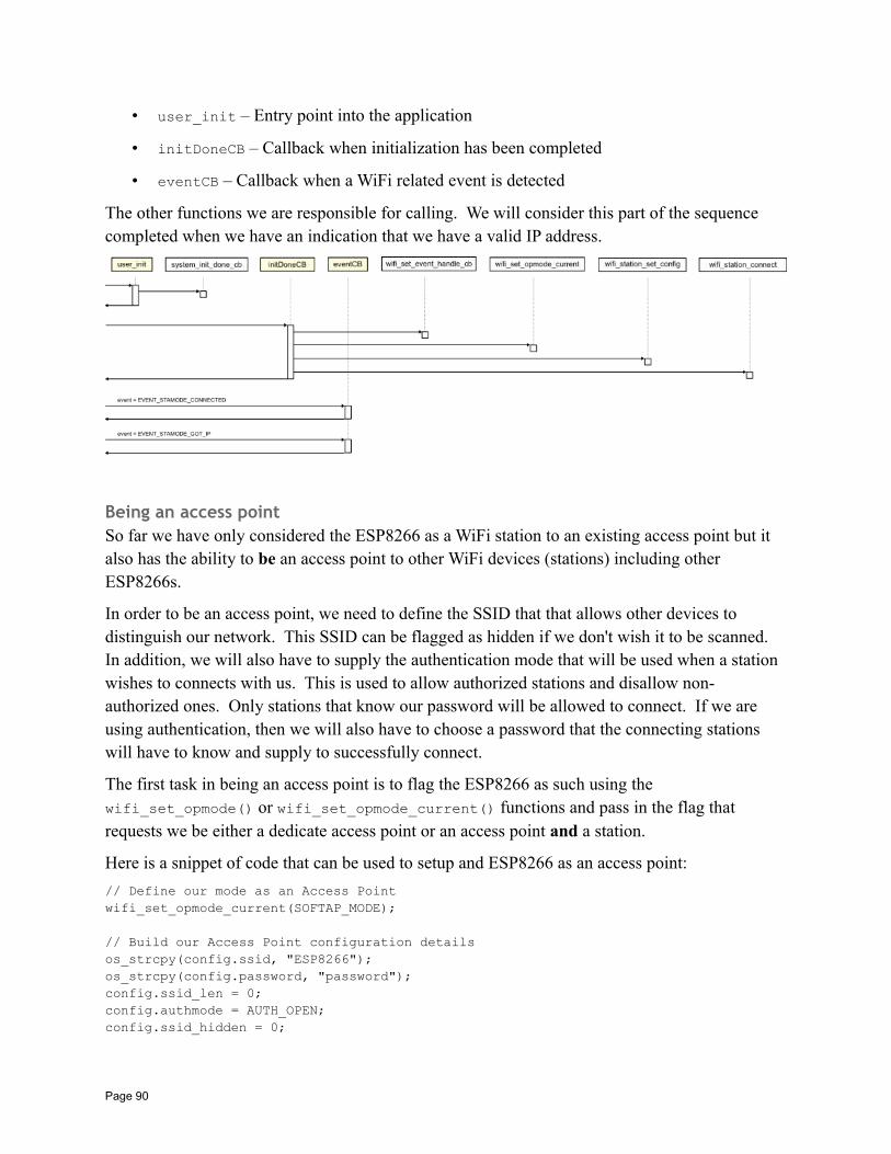
• user_init – Entry point into the application
• initDoneCB – Callback when initialization has been completed
• eventCB – Callback when a WiFi related event is detected
The other functions we are responsible for calling. We will consider this part of the sequence completed when we have an indication that we have a valid IP address.
Being an access pointSo far we have only considered the ESP8266 as a WiFi station to an existing access point but it also has the ability to be an access point to other WiFi devices (stations) including other ESP8266s.
In order to be an access point, we need to define the SSID that that allows other devices to distinguish our network. This SSID can be flagged as hidden if we don't wish it to be scanned. In addition, we will also have to supply the authentication mode that will be used when a station wishes to connects with us. This is used to allow authorized stations and disallow non-authorized ones. Only stations that know our password will be allowed to connect. If we are using authentication, then we will also have to choose a password that the connecting stations will have to know and supply to successfully connect.
The first task in being an access point is to flag the ESP8266 as such using the wifi_set_opmode() or wifi_set_opmode_current() functions and pass in the flag that requests we be either a dedicate access point or an access point and a station.
Here is a snippet of code that can be used to setup and ESP8266 as an access point:
// Define our mode as an Access Pointwifi_set_opmode_current(SOFTAP_MODE);
// Build our Access Point configuration detailsos_strcpy(config.ssid, "ESP8266");os_strcpy(config.password, "password");config.ssid_len = 0;config.authmode = AUTH_OPEN;config.ssid_hidden = 0;
Page 90
config.max_connection = 4;wifi_softap_set_config_current(&config);
When a remote station connects to the ESP8266 as an access point, we will see a debug message written to UART1 that may look similar to:
station: f0:25:b7:ff:12:c5 join, AID = 1
This contains the MAC address of the new station joining the network. When the station disconnects, we will see a corresponding debug log message that may be:
station: f0:25:b7:ff:12:c5 leave, AID = 1
From within the ESP8266, we can determine how many stations are currently connected with a call to wifi_softap_get_station_num(). If we wish to find the details of those stations, we can call wifi_softap_get_station_info() which will return a linked list of struct station_info. We have to explicitly release the storage allocated by this call with an invocation of wifi_softap_free_station_info().
Here is an example of a snippet of code that lists the details of the connected stations:
uint8 stationCount = wifi_softap_get_station_num();os_printf("stationCount = %d\n", stationCount);struct station_info *stationInfo = wifi_softap_get_station_info();if (stationInfo != NULL)
while (stationInfo != NULL) os_printf("Station IP: %d.%d.%d.%d\n", IP2STR(&(stationInfo->ip)));stationInfo = STAILQ_NEXT(stationInfo, next);
wifi_softap_free_station_info();
When an ESP8266 acts as an access point, this allows other devices to connect to it and form a WiFi connection. However, it appears that two devices connected to the same ESP8266 acting asan access point can not directly communicate between each other. For example, imagine two devices connecting to an ESP8266 as an access point. They may be allocated the IP addresses 192.168.4.2 and 192.168.4.3. We might imagine that 192.168.4.2 could ping 192.168.4.3 and visa versa but that its not allowed. It appears that they only direct network connection permitted is between the newly connected stations and the access point (the ESP8266) itself.
This seems to limit the applicability of the ESP8266 as an access point. The primary intent of the ESP8266 as an access point is to allow mobile devices (eg. your phone) to connect to the ESP8266 and have a conversation with an application that runs upon it.
See also:
• wifi_set_opmode• wifi_set_opmode_current• wifi_softap_set_config• wifi_softap_set_config_current• wifi_softap_get_station_num• wifi_softap_get_station_info• wifi_softap_free_station_info
Page 91
The DHCP serverWhen the ESP8266 is performing the role of an access point, it is likely that you will want it to also behave as a DHCP server so that connecting stations will be able to be automatically assigned IP addresses and learn their subnet masks and gateways.
The DHCP server can be started and stopped within the device using the APIs called wifi_softap_dhcps_start() and wifi_softap_dhcps_stop(). The current status (started or stopped) of the DHCP server can be found with a call to wifi_softap_dhcps_status().
The default range of IP addresses offered by the DHCP server is 192.168.4.1 upwards. The first address becomes assigned to the ESP8266 itself. It is important to realize that this address range is not the same address range as your LAN where you may be working. The ESP8266 has formed its own network address space and even though they may appear with the same sorts of numbers (192.168.x.x) they are isolated and independent networks. If you start an access point on the ESP8266 and connect to it from your phone, don't be surprised when you try and ping it from your Internet connected PC and don't get a response.
See also:
• wifi_softap_dhcps_start• wifi_softap_dhcps_stop• wifi_softap_set_dhcps_lease• wifi_softap_dhcps_status
Current IP Address, netmask and gatewayShould we need it, we can query the OS environment for the current IP address, netmask and gateway. The values of these are commonly set for us by a DHCP server when we connect to an access point. The function called wifi_get_ip_info() returns our current information while the function called wifi_set_ip_info() allows us to set our addresses.
When we connect to an access point and have chosen to use DHCP, when we are allocated an IP address, an event is generated that can be used as an indication that we now have a valid IP address.
To correctly setup static IP addresses, in the init_done callback, call wifi_station_dhcpc_stop() to disable the DHCP client running in the ESP8266. After this call wifi_station_connect() to start the access point connection phase. When the event arrives that indicates we are connected to an access point as a station (EVENT_STAMODE_CONNECTED), we can call wifi_set_ip_info() and pass in the IP address, gateway and netmask that we wish to use. Note that when we use a static IP address, we will notreceive the callback event that indicates we have received an IP address (EVENT_STAMODE_GOT_IP) as we already have it.
See also:
Page 92
• Handling WiFi events• wifi_get_ip_info• wifi_set_ip_info• wifi_station_dhcpc_stop• struct ip_info
WiFi Protected Setup – WPSThe ESP8266 supports WiFi Protected Setup in station mode. This means that if the access pointsupports it, the ESP8266 can connect to the access point without presenting a password. Currently only the "push button mode" of connection is implemented. Using this mechanism, a physical button is pressed on the access point and, for a period of two minutes, any station in range can join the network using the WPS protocols. An example of use would be the access point WPS button being pressed and then the ESP8266 device calling wifi_wps_enable() and then wifi_wps_start(). The ESP8266 would then connect to the network.
See also:
• wifi_wps_enable• wifi_wps_start• wifi_set_wps_cb• Simple Questions: What is WPS (WiFi Protected Setup)• Wikipedia: WiFi Protected Setup
Working with TCP/IPTCP/IP is the network protocol that is used on the Internet. It is the protocol that the ESP8266 natively understands and uses with WiFi as the transport. Books upon books have already been written about TCP/IP and our goal is not to attempt to reproduce a detailed discussion of how it works, however, there are some concepts that we will try and capture.
First, there is the IP address. This is a 32bit value and should be unique to every device connected to the Internet. A 32bit value can be thought of as four distinct 8bit values (4x8=32). Since we can represent an 8bit number as a decimal value between 0 and 255, we commonly represent IP addresses with the notation <number>.<number>.<number>.<number> for example 173.194.64.102. These IP addresses are not commonly entered in applications. Instead a textual name is typed such as "google.com" … but don't be misled, these names are an illusion at the TCP/IP level. All work is performed with 32bit IP addresses. There is a mapping system that takes a name (such as "google.com") and retrieves its corresponding IP address. The technologythat does this is called the "Domain Name System" or DNS.
When we think of TCP/IP, there are actually three distinct protocols at play here. The first is IP (Internet Protocol). This is the underlying transport layer datagram passing protocol. Above the IP layer is TCP (Transmission Control Protocol) which provides the illusion of a connection overthe connectionless IP protocol. Finally there is UDP (User Datagram Protocol). This too lives above the IP protocol and provides datagram (connectionless) transmission between applications.When we say TCP/IP, we are not just talking about TCP running over IP but are in fact using this
Page 93
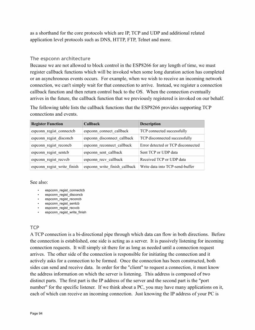
as a shorthand for the core protocols which are IP, TCP and UDP and additional related application level protocols such as DNS, HTTP, FTP, Telnet and more.
The espconn architectureBecause we are not allowed to block control in the ESP8266 for any length of time, we must register callback functions which will be invoked when some long duration action has completedor an asynchronous events occurs. For example, when we wish to receive an incoming network connection, we can't simply wait for that connection to arrive. Instead, we register a connection callback function and then return control back to the OS. When the connection eventually arrives in the future, the callback function that we previously registered is invoked on our behalf.
The following table lists the callback functions that the ESP8266 provides supporting TCP connections and events.
Register Function Callback Description
espconn_regist_connectcb espconn_connect_callback TCP connected successfully
espconn_regist_disconcb espconn_disconnect_callback TCP disconnected successfully
espconn_regist_reconcb espconn_reconnect_callback Error detected or TCP disconnected
espconn_regist_sentcb espconn_sent_callback Sent TCP or UDP data
espconn_regist_recvcb espconn_recv_callback Received TCP or UDP data
espconn_regist_write_finish espconn_write_finish_callback Write data into TCP-send-buffer
See also:
• espconn_regist_connectcb• espconn_regist_disconcb• espconn_regist_reconcb• espconn_regist_sentcb• espconn_regist_recvcb• espconn_regist_write_finish
TCPA TCP connection is a bi-directional pipe through which data can flow in both directions. Beforethe connection is established, one side is acting as a server. It is passively listening for incoming connection requests. It will simply sit there for as long as needed until a connection request arrives. The other side of the connection is responsible for initiating the connection and it actively asks for a connection to be formed. Once the connection has been constructed, both sides can send and receive data. In order for the "client" to request a connection, it must know the address information on which the server is listening. This address is composed of two distinct parts. The first part is the IP address of the server and the second part is the "port number" for the specific listener. If we think about a PC, you may have many applications on it, each of which can receive an incoming connection. Just knowing the IP address of your PC is
Page 94
not sufficient to address a connection to the correct application. The combination of IP address plus port number provides all the addressing necessary.
As an analogy to this, think of your cell phone. It is passively sitting there until someone calls it.In our story, it is the listener. The address that someone uses to form a connection is your phone number which is comprised of an area code plus the remainder. For example, a phone number of(817) 555-1234 will reach a particular phone. However the area code of 817 is for Fort Worth in Texas … calling that by itself is not sufficient to reach an individual … the full phone number is required.
No we will look at how an ESP8266 can set itself up as a listener for an incoming TCP/IP connection.
We start by introducing an absolutely vital data structure that is called "struct espconn". This data structure contains much of the "state" of our connection and is passed into most of our TCP APIs.
We initialize it by setting a number of its fields:
• type – This is the type of connection we are going to use. Since we want to use a TCP connection as opposed to a UDP connection, we supply ESPCONN_TCP as the value.
• state – The state of the connection will change over time but we initialize it to have an initial empty state by supplying ESPCONN_NONE.
For example:
struct espconn conn1;
void init() conn1.type = ESPCONN_TCP;conn1.state = ESPCONN_NONE;
Now we introduce another structure called "esp_tcp". This structure contains TCP specific settings. For our story, this is where we supply the port number which our TCP connection will listen upon for client connections. This is supplied in the property called "local_port".
esp_tcp tcp1;
void init() tcp1.local_port = 25867;
Within the struct espconn data type, there is a field called "proto" which is a pointer to a protocol specific data structure. For a TCP connection, this will be a pointer to an "esp_tcp" instance … and this is where we get to glue the story together. The full code becomes:
struct espconn conn1;esp_tcp tcp1;
void init()
Page 95
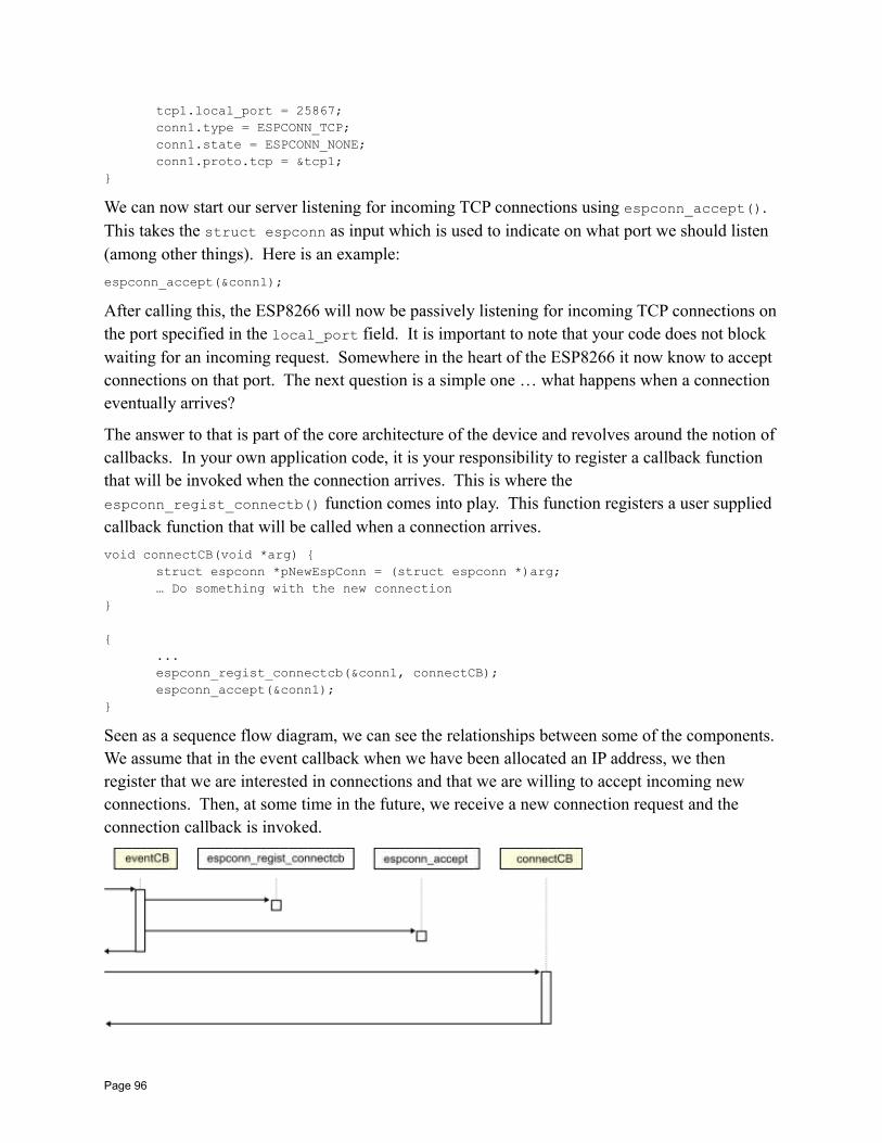
tcp1.local_port = 25867;conn1.type = ESPCONN_TCP;conn1.state = ESPCONN_NONE;conn1.proto.tcp = &tcp1;
We can now start our server listening for incoming TCP connections using espconn_accept(). This takes the struct espconn as input which is used to indicate on what port we should listen (among other things). Here is an example:
espconn_accept(&conn1);
After calling this, the ESP8266 will now be passively listening for incoming TCP connections onthe port specified in the local_port field. It is important to note that your code does not block waiting for an incoming request. Somewhere in the heart of the ESP8266 it now know to accept connections on that port. The next question is a simple one … what happens when a connection eventually arrives?
The answer to that is part of the core architecture of the device and revolves around the notion ofcallbacks. In your own application code, it is your responsibility to register a callback function that will be invoked when the connection arrives. This is where the espconn_regist_connectb() function comes into play. This function registers a user supplied callback function that will be called when a connection arrives.
void connectCB(void *arg) struct espconn *pNewEspConn = (struct espconn *)arg;… Do something with the new connection
...espconn_regist_connectcb(&conn1, connectCB);espconn_accept(&conn1);
Seen as a sequence flow diagram, we can see the relationships between some of the components. We assume that in the event callback when we have been allocated an IP address, we then register that we are interested in connections and that we are willing to accept incoming new connections. Then, at some time in the future, we receive a new connection request and the connection callback is invoked.
Page 96
The content of the struct espconn passed into the callback will include the remote IP address of the partner that connected with us. We can use that information for logging or for authorization. For example, if the IP address is not one we wish to allow, we can disconnect at this point using espconn_disconnect(). Realize that this data structure represents the new connection with the partner that just invoked up and is not the same as struct espconn that was used to register that we wanted to accept new connections. A new struct espconn will be passed in for each new connection formed.
This covers the ESP8266 receiving incoming connection requests, but what if it should desire to form a connection outbound to a remote TCP application? To perform an outbound connection request we can use the espconn_connect() call. Prior to making this call, we must set up the TCP structure. The field remote_port must contain the port number of the application partner to which we wish to connect. In addition the remote_ip field must contain the IP address of the machine hosting the partner. The local_port must be assigned an unused local port using espconn_port(). The local_ip must also be completed using the local IP address. Just like the receiving an inbound connection, making an outbound connection will result in an invocationto the connection callback when the connection is established. Once the connection has been formed, once again, the two ends of the connection will be peers of each other. It is vital to realize that just issuing an espconn_connect() does not result in an immediate connection. Instead, only after the connectCB has been received can we actually use the connection.
For example:
struct espconn conn1;esp_tcp tcp1;
void init() tcp1.remote_port = 25867;tcp1.remote_ip = ipAddress;tcp1.local_port = espconn_port();struct ip_info ipconfig;wifi_get_ip_info(STATION_IF, &ipconfig);os_memcpy(tcp.local_ip, &ipconfig.ip, 4);
conn1.type = ESPCONN_TCP;conn1.state = ESPCONN_NONE;conn1.proto.tcp = &tcp1;
If the partner in our conversation should close the connection, we will be informed of that through the function we register with espconn_regist_disconcb(). The state field of the struct espconn will contain CLOSE. Detection the graceful shutdown of a partner allows us to perform logic that we may need such as releasing resources or persisting data.
If a TCP connection is formed and no traffic flows over the connection for at least 10 seconds (default), then the connection is automatically closed from the ESP8266 end. The idle connection timeout property can be set with the espconn_regist_time() function.
Page 97
The ESP8266 support a maximum of 5 concurrent TCP connections.
See also:
• espconn_accept• espconn_connect• espconn_disconnect• espconn_regist_connectcb• espconn_regist_disconcb• espconn_regist_time• struct espconn• esp_tcp
Sending and receiving TCP dataAt this point, let us now assume that we have a connection between an ESP8266 and a partner application. Having a connection is great but now we need to have a conversation. Information and data needs to flow in one or both directions. There are two considerations… we may receivedata from the partner or we may wish to send data to the partner. It is important to note that in TCP, a connection is bidirectional. Once the connection has been established, either party can send data at any time. There is no concept of one party having exclusive sending or receiving rights. The choice of who is the receiver and who is the transmitter is purely up to the design of the application.
For example, imagine we had a project to turn on an LED at an ESP8266 when it receives a "1" character and turn it off when it receives a "0" character. In that story, the ESP8266 would be exclusively a receiver and, simply by our choices, need not transmit data. The partner would be exclusively a transmitter.
Now let us consider a second example. In this case the ESP8266 is connected to a temperature sensor and every few seconds it sends the current temperature to the partner. In that story, the ESP8266 is exclusively a transmitter and the partner only a receiver.
Finally, we can image an ESP8266 connected to multiple sensors. It receives commands from the partner as input which it interprets. Based on the received data, the correct sensor is chosen, its value read and the results transmitted back. In this story, the ESP8266 is at first a receiver and then becomes a transmitter while the partner is the opposite.
To receive data from a partner, we register a callback function using espconn_regist_recvcb(). We pass in the struct espconn that was supplied in the connected callback that identifies our connection. This registered callback function is invoked when new data becomes available from the partner. The callback function is passed a buffer containing the data and an indicator of how much data was received.
The following is an example of logging data that is received over the network:
void recvCB(void *arg, char *pData, unsigned short len) struct espconn *pEspConn = (struct espconn *)arg;os_printf("Received data!! - length = %d\n", len);int i=0;
Page 98

for (i=0; i<len; i++) os_printf("%c", pData[i]);
os_printf("\n");
// End of recvCB
The function called recvCB() is registered as a callback when data is available for the connection. With this in mind, we can start running some experiments and the results will be interesting.
If we send data, we see the callback being invoked as expected. However, as the size of the data transmitted, which is received by the ESP8266, increases, at about 1460 bytes, a strange thing happens. Instead of recvCB() being called once, we see it being called twice. The first time it gets the first 1460 bytes and the second time it gets what remains. This is repeated for increments of 1460 byte transmission sizes. For example, if we send 5000 bytes, recvCB() is called 4 times. The first three times with 1460 bytes of data and the last with 620 bytes giving a total of 5000.
Why would this be? Part of the answer is that the ESP8266 has only a very small amount of RAM available to it and needs to be able to support parallel connections. As such, it can apparently throttle the data being sent from the sender until space is available to process it.
It can't be stressed enough the importance of this concept. Data sent from the server over a TCP connection is "streamed" to the ESP8266. There is no concept of a unit of data transmission. Instead data sent in the pipe at the sender will arrive at the ESP8266 but it may very well arrive at different rates. The order of the transmitted data is preserved (obviously). In principle, making two transmissions at the sender of 5 bytes each could result in one receive at the ESP8266 of 10 bytes. or just as easily one receive of 1 byte and one receive of 9 bytes. Don't make any assumptions about the bracketing of TCP data.
To transmit data to a partner we use the function called espconn_send().
This command takes the struct espconn which identifies which connection to send data through. The function also takes a pointer to a buffer of data and the length of the data to send. A vital consideration is that the data to be sent is not sent immediately. When we call espconn_sent() what we are doing is handing off a buffer of data to be transmitted at some time in the future. We anticipate this will be a few milliseconds but it could be longer. We must honor the contract. When the ESP8266 does successfully transmit the data, a callback will be made to a function that was registered with the espconn_regist_sentcb(). Only after having seen a confirmation that the last transmission request has been completed should we execute another espconn_send() request.
When we ask for data to be transmitted, we provide a pointer to a buffer that contains the data. Itis important to realize that we must maintain that data until after we are sure its content has been sent. For example, we can't request a transmission and then immediately dispose off or change
Page 99
the buffer. What we hand off to the OS is a pointer to a buffer and until the OS tells us that it hasfinished consuming it, we must maintain its integrity.
See also:
• espconn_regist_recvcb• espconn_send
Flow controlConsider the notion of an ESP8266 in communication with a partner and the partner is sending 5K of data per second. Now imagine that the ESP8266 is only processing 1K of data per second.As you can see, something will go wrong quite quickly. We will overwhelm the ESP8266 with too much data. What we really want is to institute a flow control mechanism such that the senderof the data is told to throttle back its delivery of data to a rate that the ESP8266 can accommodate. The send may choose to buffer data at its end or else may be told to not send so much data per unit of time by pushing back to the original transmitting logic.
See also:
• espconn_recv_hold• espconn_recv_unhold
TCP Error handlingWhen a connection is formed between two partners it is essential that we realize that there isn't an actual dedicated underlying connection between them. Instead, there is only a logical connection that appears to be present over the datagram oriented protocol of IP. What this might mean is that if one end of the connection abnormally ends, the other end won't immediately know about it. As an example, if in the real world I make a phone call to you then your phone indicates to you that we have a connection. If the battery on my phone dies the telephone network detects that and drops the connection. Your phone also hangs up and you know we are no longer in communication. In the TCP world, that doesn't happen. If my "TCP" phone dies, your "TCP" phone isn't told that mine is gone. You may be left sitting there indefinitely listeningto silence and waiting for me to say something.
To resolve that situation, TCP introduces a concept called "keep-alive". The notion is very simple. With keep-alive, the two partners periodically exchange a heartbeat communication witheach other. As long as they each hear the heartbeat of the other, they are both still present. However, if one side of the connection is lost, the heartbeat request will be sent but no response will arrive at which point, the one sending the heartbeat will assume that the partner has gone and we can take appropriate cleanup and shutdown actions.
There is an API available to us to control the keep-alive settings. It is called espconn_set_keepalive(). It has a number of properties including:
Page 100
• How long should we wait since the last time we heard from the partner before sending a heartbeat?
• If no response, how long between subsequent heartbeats?
• How many times should we send a heartbeat until we declare the partner dead?
It is recommended that if keep-alive processing is to be used then the keep-alive settings be madein the callback handler of the connect callback. The keep-alive option must also be explicitly enabled using the espconn_set_opt() call prior to setting the keep-alive properties.
If the partner connection is lost, we can detect that by registering a callback function with espconn_reconnect_callback().
See also:
• espconn_set_keepalive• espconn_get_keepalive• espconn_set_opt• espconn_clear_opt
UDPIf we think of TCP as forming a connection between two parties similar to a telephone call, then UDP is like sending a letter through the postal system. If I were to send you a letter, I would need to know your name and address. Your address is needed so that the letter can be delivered to the correct house while your name ensure that it ends up in your hands as opposed to someoneelse who may live with you. In TCP/IP terms, the address is the IP address and the name is the port number.
With a telephone conversation, we can exchange as much or as little information as we like. Sometimes I talk, sometimes you talk … but there is no maximum limit on how much information we can exchange in one conversation. With a letter however, there are only so manypages of paper that will fit in the envelopes I have at my disposal.
The notion of the mail analogy is how we might choose to think about UDP. The acronym stands for User Datagram Protocol and it is the notion of the datagram that is akin to the letter. Adatagram is an array of bytes that are transmitted from the sender to the receiver as a unit. The maximum size of a datagram using UDP is 64KBytes. No connection need be setup between thetwo parties before data starts to flow. However, there is a down side. The sender of the data willnot be made aware of a receiver's failure to retrieve the data. With TCP, we have handshaking between the two parties that lets the sender know that the data was received and, if not, can automatically retransmit until it has been received or we decide to give up. With UDP, and just like a letter, when we send a datagram, we lose sight of whether or not it actually arrives safely atthe destination.
If we wish to receive incoming datagrams, we must register what port number we are interested in receiving them upon. We achieve that through the poorly named espconn_create()
Page 101
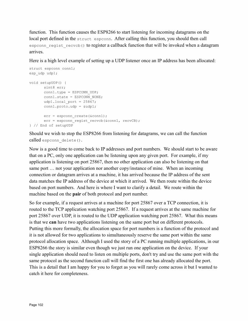
function. This function causes the ESP8266 to start listening for incoming datagrams on the local port defined in the struct espconn. After calling this function, you should then call espconn_regist_recvcb() to register a callback function that will be invoked when a datagramarrives.
Here is a high level example of setting up a UDP listener once an IP address has been allocated:
struct espconn conn1;esp_udp udp1;
void setupUDP() sint8 err;conn1.type = ESPCONN_UDP;conn1.state = ESPCONN_NONE;udp1.local_port = 25867;conn1.proto.udp = &udp1;
err = espconn_create(&conn1);err = espconn_regist_recvcb(&conn1, recvCB);
// End of setupUDP
Should we wish to stop the ESP8266 from listening for datagrams, we can call the function called espconn_delete().
Now is a good time to come back to IP addresses and port numbers. We should start to be aware that on a PC, only one application can be listening upon any given port. For example, if my application is listening on port 25867, then no other application can also be listening on that same port … not your application nor another copy/instance of mine. When an incoming connection or datagram arrives at a machine, it has arrived because the IP address of the sent data matches the IP address of the device at which it arrived. We then route within the device based on port numbers. And here is where I want to clarify a detail. We route within the machine based on the pair of both protocol and port number.
So for example, if a request arrives at a machine for port 25867 over a TCP connection, it is routed to the TCP application watching port 25867. If a request arrives at the same machine for port 25867 over UDP, it is routed to the UDP application watching port 25867. What this means is that we can have two applications listening on the same port but on different protocols. Putting this more formally, the allocation space for port numbers is a function of the protocol andit is not allowed for two applications to simultaneously reserve the same port within the same protocol allocation space. Although I used the story of a PC running multiple applications, in ourESP8266 the story is similar even though we just run one application on the device. If your single application should need to listen on multiple ports, don't try and use the same port with thesame protocol as the second function call will find the first one has already allocated the port. This is a detail that I am happy for you to forget as you will rarely come across it but I wanted to catch it here for completeness.
Page 102
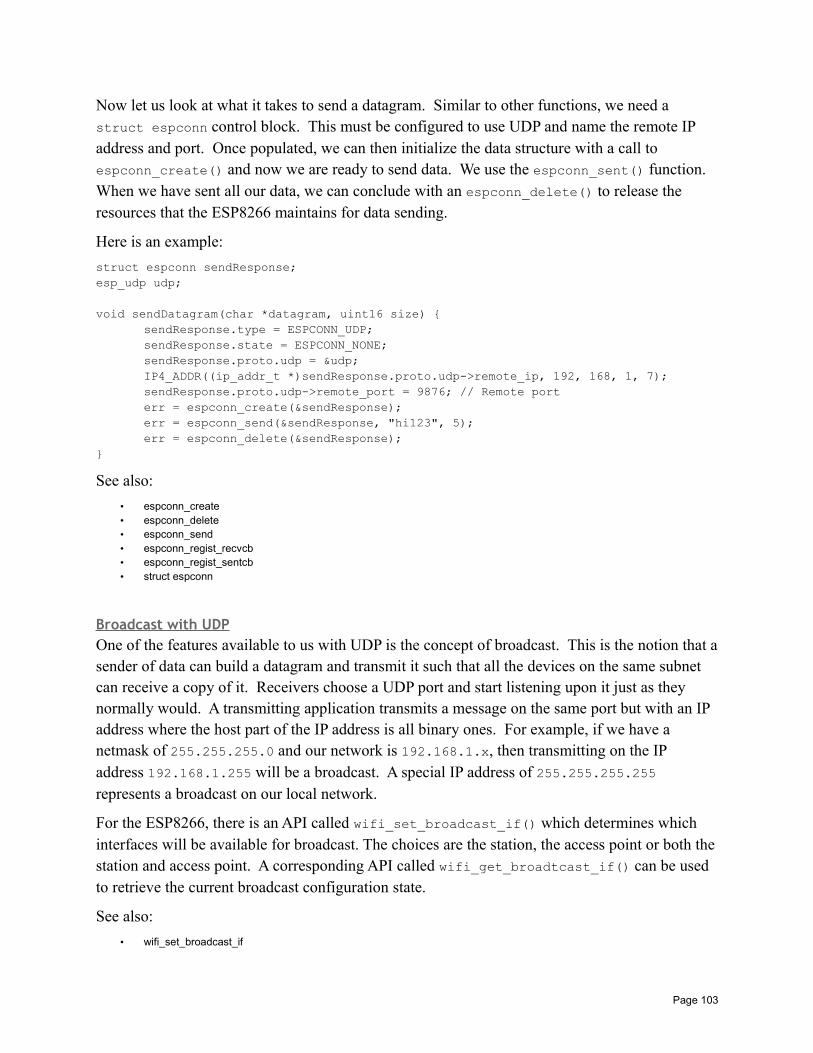
Now let us look at what it takes to send a datagram. Similar to other functions, we need a struct espconn control block. This must be configured to use UDP and name the remote IP address and port. Once populated, we can then initialize the data structure with a call to espconn_create() and now we are ready to send data. We use the espconn_sent() function. When we have sent all our data, we can conclude with an espconn_delete() to release the resources that the ESP8266 maintains for data sending.
Here is an example:
struct espconn sendResponse;esp_udp udp;
void sendDatagram(char *datagram, uint16 size) sendResponse.type = ESPCONN_UDP;sendResponse.state = ESPCONN_NONE;sendResponse.proto.udp = &udp;IP4_ADDR((ip_addr_t *)sendResponse.proto.udp->remote_ip, 192, 168, 1, 7);sendResponse.proto.udp->remote_port = 9876; // Remote porterr = espconn_create(&sendResponse);err = espconn_send(&sendResponse, "hi123", 5);err = espconn_delete(&sendResponse);
See also:
• espconn_create• espconn_delete• espconn_send• espconn_regist_recvcb• espconn_regist_sentcb• struct espconn
Broadcast with UDPOne of the features available to us with UDP is the concept of broadcast. This is the notion that asender of data can build a datagram and transmit it such that all the devices on the same subnet can receive a copy of it. Receivers choose a UDP port and start listening upon it just as they normally would. A transmitting application transmits a message on the same port but with an IP address where the host part of the IP address is all binary ones. For example, if we have a netmask of 255.255.255.0 and our network is 192.168.1.x, then transmitting on the IP address 192.168.1.255 will be a broadcast. A special IP address of 255.255.255.255 represents a broadcast on our local network.
For the ESP8266, there is an API called wifi_set_broadcast_if() which determines which interfaces will be available for broadcast. The choices are the station, the access point or both thestation and access point. A corresponding API called wifi_get_broadtcast_if() can be used to retrieve the current broadcast configuration state.
See also:
• wifi_set_broadcast_if
Page 103
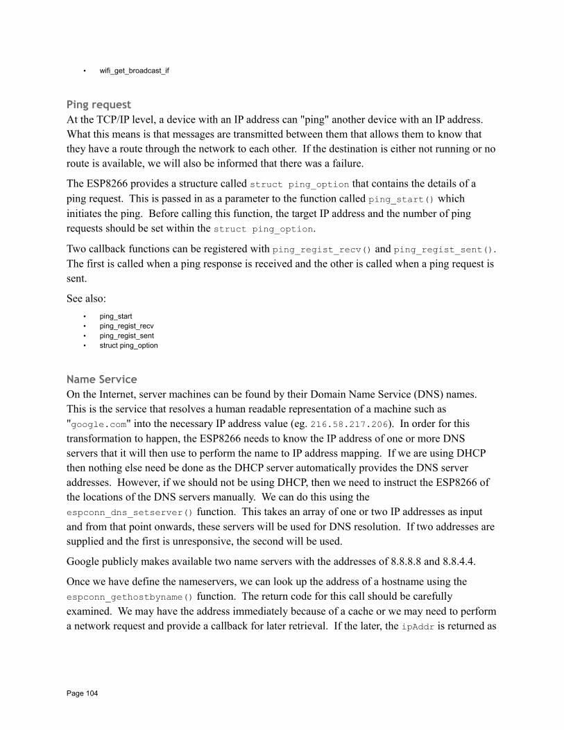
• wifi_get_broadcast_if
Ping requestAt the TCP/IP level, a device with an IP address can "ping" another device with an IP address. What this means is that messages are transmitted between them that allows them to know that they have a route through the network to each other. If the destination is either not running or noroute is available, we will also be informed that there was a failure.
The ESP8266 provides a structure called struct ping_option that contains the details of a ping request. This is passed in as a parameter to the function called ping_start() which initiates the ping. Before calling this function, the target IP address and the number of ping requests should be set within the struct ping_option.
Two callback functions can be registered with ping_regist_recv() and ping_regist_sent().The first is called when a ping response is received and the other is called when a ping request is sent.
See also:
• ping_start• ping_regist_recv• ping_regist_sent• struct ping_option
Name ServiceOn the Internet, server machines can be found by their Domain Name Service (DNS) names. This is the service that resolves a human readable representation of a machine such as "google.com" into the necessary IP address value (eg. 216.58.217.206). In order for this transformation to happen, the ESP8266 needs to know the IP address of one or more DNS servers that it will then use to perform the name to IP address mapping. If we are using DHCP then nothing else need be done as the DHCP server automatically provides the DNS server addresses. However, if we should not be using DHCP, then we need to instruct the ESP8266 of the locations of the DNS servers manually. We can do this using the espconn_dns_setserver() function. This takes an array of one or two IP addresses as input and from that point onwards, these servers will be used for DNS resolution. If two addresses are supplied and the first is unresponsive, the second will be used.
Google publicly makes available two name servers with the addresses of 8.8.8.8 and 8.8.4.4.
Once we have define the nameservers, we can look up the address of a hostname using the espconn_gethostbyname() function. The return code for this call should be carefully examined. We may have the address immediately because of a cache or we may need to performa network request and provide a callback for later retrieval. If the later, the ipAddr is returned as
Page 104
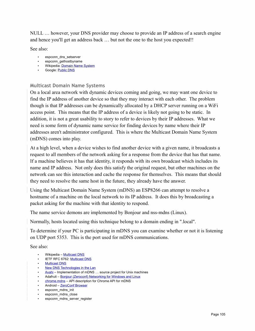
NULL … however, your DNS provider may choose to provide an IP address of a search engine and hence you'll get an address back … but not the one to the host you expected!!
See also:
• espconn_dns_setserver• espconn_gethostbyname• Wikipedia: Domain Name System• Google: Public DNS
Multicast Domain Name SystemsOn a local area network with dynamic devices coming and going, we may want one device to find the IP address of another device so that they may interact with each other. The problem though is that IP addresses can be dynamically allocated by a DHCP server running on a WiFi access point. This means that the IP address of a device is likely not going to be static. In addition, it is not a great usability to story to refer to devices by their IP addresses. What we need is some form of dynamic name service for finding devices by name where their IP addresses aren't administrator configured. This is where the Multicast Domain Name System (mDNS) comes into play.
At a high level, when a device wishes to find another device with a given name, it broadcasts a request to all members of the network asking for a response from the device that has that name. If a machine believes it has that identity, it responds with its own broadcast which includes its name and IP address. Not only does this satisfy the original request, but other machines on the network can see this interaction and cache the response for themselves. This means that should they need to resolve the same host in the future, they already have the answer.
Using the Multicast Domain Name System (mDNS) an ESP8266 can attempt to resolve a hostname of a machine on the local network to its IP address. It does this by broadcasting a packet asking for the machine with that identity to respond.
The name service demons are implemented by Bonjour and nss-mdns (Linux).
Normally, hosts located using this technique belong to a domain ending in ".local".
To determine if your PC is participating in mDNS you can examine whether or not it is listening on UDP port 5353. This is the port used for mDNS communications.
See also:
• Wikipedia – Multicast DNS• IETF RFC 6762: Multicast DNS• Multicast DNS• New DNS Technologies in the Lan• Avahi – Implementation of mDNS … source project for Unix machines• Adafruit – Bonjour (Zeroconf) Networking for Windows and Linux• chrome.mdns – API description for Chrome API for mDNS• Android – ZeroConf Browser• espconn_mdns_init• espconn_mdns_close• espconn_mdns_server_register
Page 105
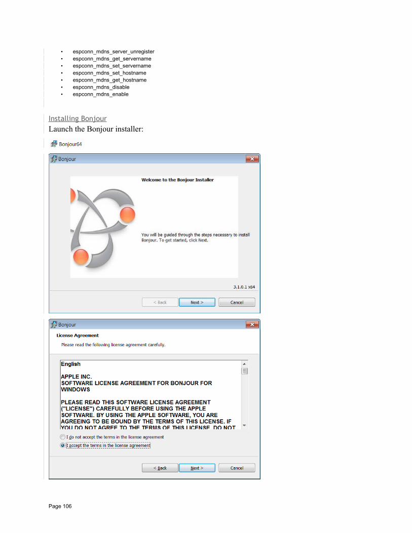
• espconn_mdns_server_unregister• espconn_mdns_get_servername• espconn_mdns_set_servername• espconn_mdns_set_hostname• espconn_mdns_get_hostname• espconn_mdns_disable• espconn_mdns_enable
Installing BonjourLaunch the Bonjour installer:
Page 106
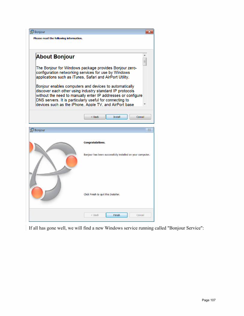
If all has gone well, we will find a new Windows service running called "Bonjour Service":
Page 107
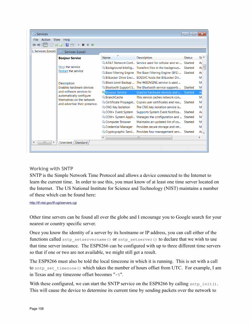
Working with SNTPSNTP is the Simple Network Time Protocol and allows a device connected to the Internet to learn the current time. In order to use this, you must know of at least one time server located on the Internet. The US National Institute for Science and Technology (NIST) maintains a number of these which can be found here:
http://tf.nist.gov/tf-cgi/servers.cgi
Other time servers can be found all over the globe and I encourage you to Google search for yournearest or country specific server.
Once you know the identity of a server by its hostname or IP address, you can call either of the functions called sntp_setservername() or sntp_setserver() to declare that we wish to use that time server instance. The ESP8266 can be configured with up to three different time serversso that if one or two are not available, we might still get a result.
The ESP8266 must also be told the local timezone in which it is running. This is set with a call to sntp_set_timezone() which takes the number of hours offset from UTC. For example, I amin Texas and my timezone offset becomes "-5".
With these configured, we can start the SNTP service on the ESP8266 by calling sntp_init(). This will cause the device to determine its current time by sending packets over the network to
Page 108
the time servers and examining their responses. It is important to note that immediately after calling sntp_init(), you will not yet know what the current time may be. This is because it may take a few seconds for the ESP8266 to sends the time requests and get their responses and this will all happen asynchronously to your current commands and won't complete till sometime later.
When ready, we can retrieve the current time with a call to sntp_get_current_timestamp() which will return the number of seconds since the 1st of January 1970 UTC. We can also call the function called sntp_get_real_time() which will return a string representation of the time.
See also:
• sntp_setserver• sntp_setservername• sntp_init• sntp_set_timezone• sntp_get_current_timestamp• sntp_get_real_time• IETF RFC5905: Network Time Protocol Version 4: Protocol and Algorithms Specification
ESP-NOWThe concept of ESP-NOW is to achieve a private protocol between sets of ESP8266s. Think of it loosely as a controller/slave relationship where we have one controller and potentially multipleslaves. The slaves form "persistent" connections to the controller. What this means is that when a slave ESP8266 is powered on, it is virtually immediately able to transmit to the controller. Compare this with the notion of the ESP8266 powering on, connecting to the access point and then connecting to the master device. These flows take timer while ESP-NOW is much faster from a startup.
To start, an ESP8266 which wishes to participate in using this protocol will invoke esp_now_init(). Should it no longer wish to be part of this kind of network, it can call esp_now_deinit(). Before communication can proceed, the device will had to add the peers inthe network. This is achieved through a call to esp_now_add_peer().
Each ESP8266 device in the network will declare itself as having a role of either a slave or a controller through a call to esp_now_set_self_role().
A corresponding esp_now_delete_peer() can be used to forget about a previously registered peer. When ready to transmit data, a call can be made to esp_now_send() supplying the addressof the recipient as well as the data to be transmitted. The maximum amount of data that can be currently sent as a unit is 256 bytes.
Two callbacks are available which are invoked when either a new message has been transmitted or a new message has been received.
See also:
• esp_now_init
Page 109
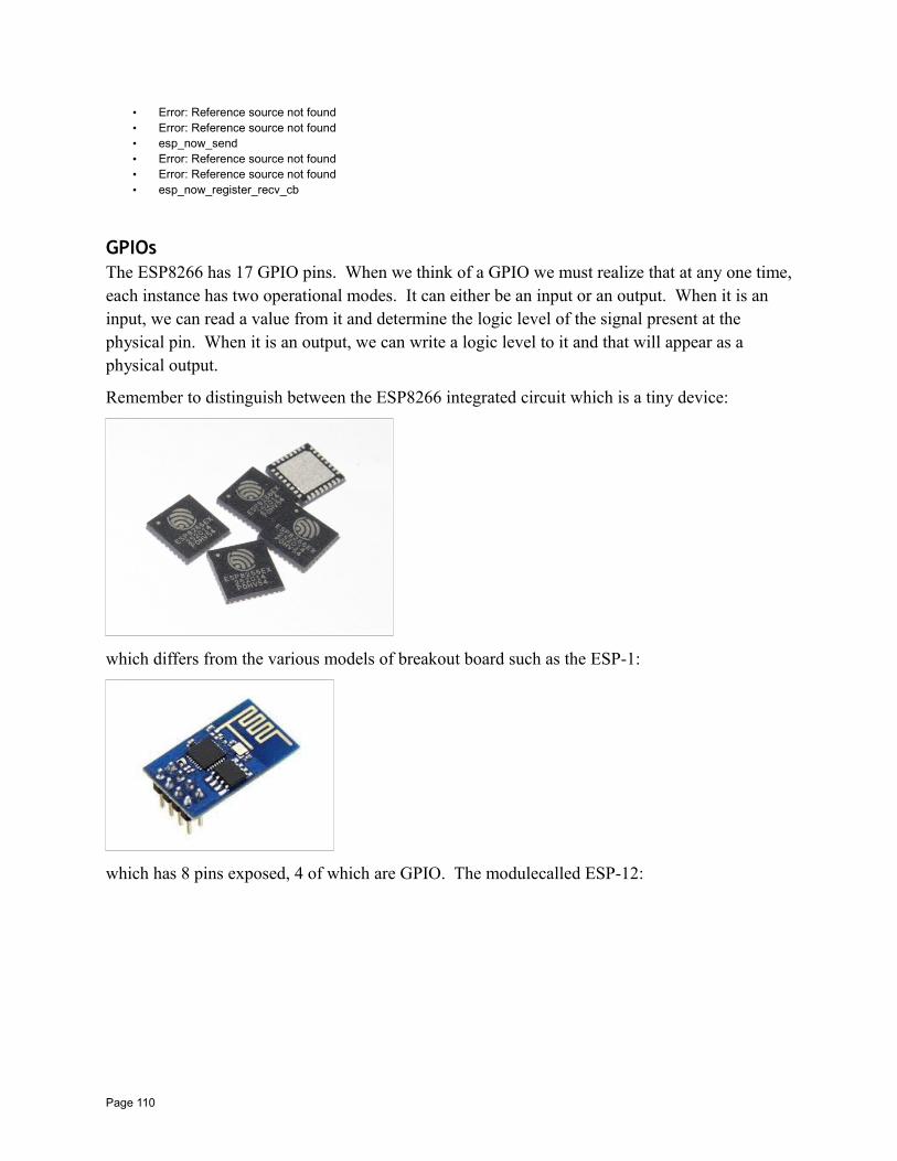
• Error: Reference source not found• Error: Reference source not found• esp_now_send• Error: Reference source not found• Error: Reference source not found• esp_now_register_recv_cb
GPIOsThe ESP8266 has 17 GPIO pins. When we think of a GPIO we must realize that at any one time,each instance has two operational modes. It can either be an input or an output. When it is an input, we can read a value from it and determine the logic level of the signal present at the physical pin. When it is an output, we can write a logic level to it and that will appear as a physical output.
Remember to distinguish between the ESP8266 integrated circuit which is a tiny device:
which differs from the various models of breakout board such as the ESP-1:
which has 8 pins exposed, 4 of which are GPIO. The modulecalled ESP-12:
Page 110
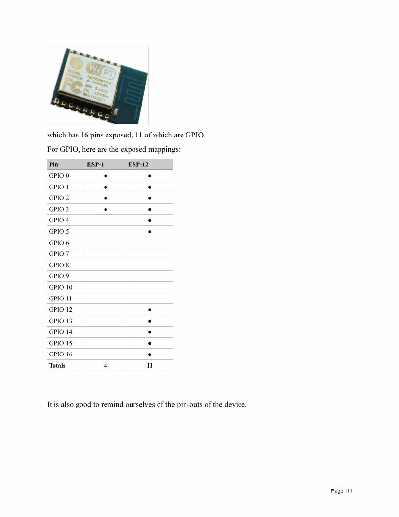
which has 16 pins exposed, 11 of which are GPIO.
For GPIO, here are the exposed mappings:
Pin ESP-1 ESP-12
GPIO 0
GPIO 1
GPIO 2
GPIO 3
GPIO 4
GPIO 5
GPIO 6
GPIO 7
GPIO 8
GPIO 9
GPIO 10
GPIO 11
GPIO 12
GPIO 13
GPIO 14
GPIO 15
GPIO 16
Totals 4 11
It is also good to remind ourselves of the pin-outs of the device.
Page 111
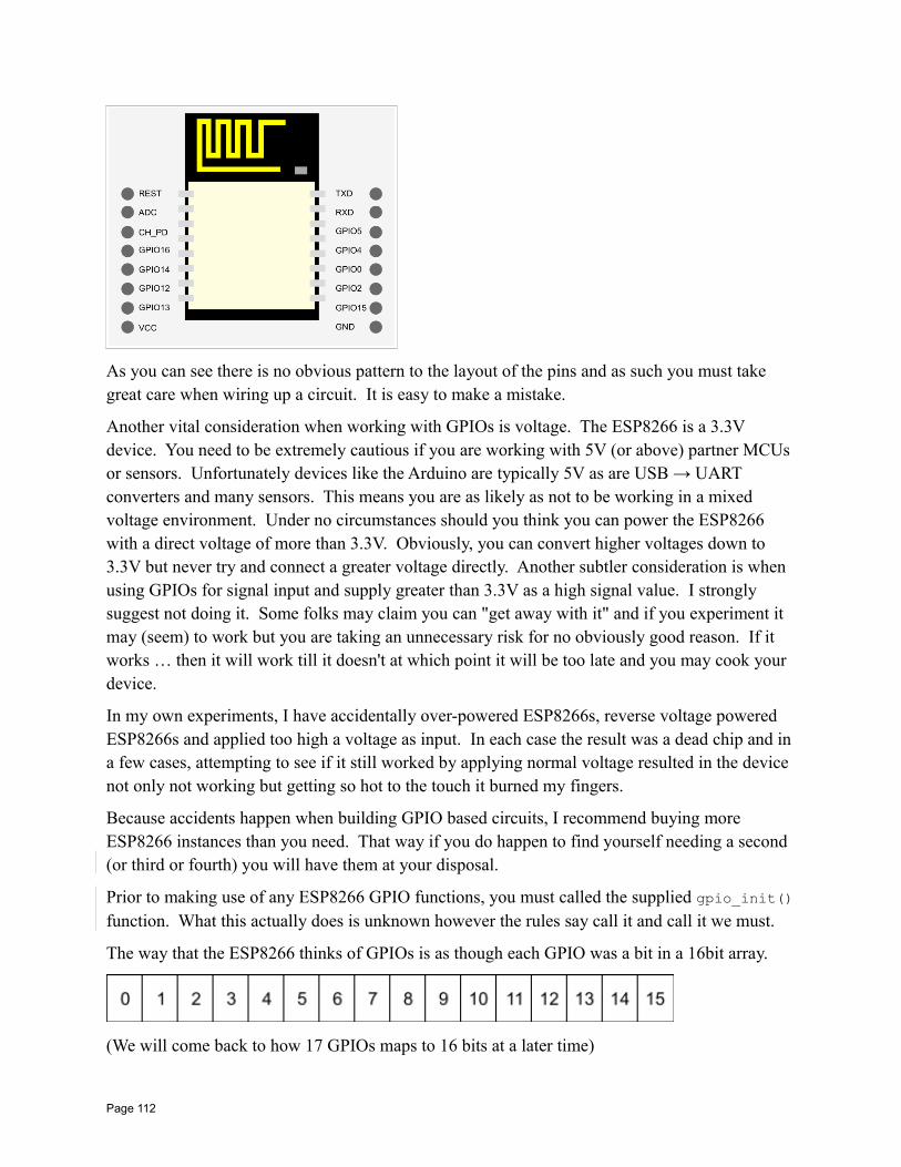
As you can see there is no obvious pattern to the layout of the pins and as such you must take great care when wiring up a circuit. It is easy to make a mistake.
Another vital consideration when working with GPIOs is voltage. The ESP8266 is a 3.3V device. You need to be extremely cautious if you are working with 5V (or above) partner MCUs or sensors. Unfortunately devices like the Arduino are typically 5V as are USB → UART converters and many sensors. This means you are as likely as not to be working in a mixed voltage environment. Under no circumstances should you think you can power the ESP8266 with a direct voltage of more than 3.3V. Obviously, you can convert higher voltages down to 3.3V but never try and connect a greater voltage directly. Another subtler consideration is when using GPIOs for signal input and supply greater than 3.3V as a high signal value. I strongly suggest not doing it. Some folks may claim you can "get away with it" and if you experiment it may (seem) to work but you are taking an unnecessary risk for no obviously good reason. If it works … then it will work till it doesn't at which point it will be too late and you may cook your device.
In my own experiments, I have accidentally over-powered ESP8266s, reverse voltage powered ESP8266s and applied too high a voltage as input. In each case the result was a dead chip and in a few cases, attempting to see if it still worked by applying normal voltage resulted in the device not only not working but getting so hot to the touch it burned my fingers.
Because accidents happen when building GPIO based circuits, I recommend buying more ESP8266 instances than you need. That way if you do happen to find yourself needing a second (or third or fourth) you will have them at your disposal.
Prior to making use of any ESP8266 GPIO functions, you must called the supplied gpio_init()function. What this actually does is unknown however the rules say call it and call it we must.
The way that the ESP8266 thinks of GPIOs is as though each GPIO was a bit in a 16bit array.
(We will come back to how 17 GPIOs maps to 16 bits at a later time)
Page 112
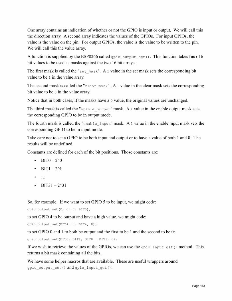
One array contains an indication of whether or not the GPIO is input or output. We will call this the direction array. A second array indicates the values of the GPIOs. For input GPIOs, the value is the value on the pin. For output GPIOs, the value is the value to be written to the pin. We will call this the value array.
A function is supplied by the ESP8266 called gpio_output_set(). This function takes four 16 bit values to be used as masks against the two 16 bit arrays.
The first mask is called the "set_mask". A 1 value in the set mask sets the corresponding bit value to be 1 in the value array.
The second mask is called the "clear_mask". A 1 value in the clear mask sets the correspondingbit value to be 0 in the value array.
Notice that in both cases, if the masks have a 0 value, the original values are unchanged.
The third mask is called the "enable_output" mask. A 1 value in the enable output mask sets the corresponding GPIO to be in output mode.
The fourth mask is called the "enable_input" mask. A 1 value in the enable input mask sets thecorresponding GPIO to be in input mode.
Take care not to set a GPIO to be both input and output or to have a value of both 1 and 0. The results will be undefined.
Constants are defined for each of the bit positions. Those constants are:
• BIT0 – 2^0
• BIT1 – 2^1
• …
• BIT31 – 2^31
So, for example. If we want to set GPIO 5 to be input, we might code:
gpio_output_set(0, 0, 0, BIT5);
to set GPIO 4 to be output and have a high value, we might code:
gpio_output_set(BIT4, 0, BIT4, 0);
to set GPIO 0 and 1 to both be output and the first to be 1 and the second to be 0:
gpio_output_set(BIT0, BIT1, BIT0 | BIT1, 0);
If we wish to retrieve the values of the GPIOs, we can use the gpio_input_get() method. This returns a bit mask containing all the bits.
We have some helper macros that are available. These are useful wrappers around gpio_output_set() and gpio_input_get().
Page 113
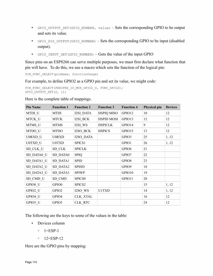
• GPIO_OUTPUT_SET(GPIO_NUMBER, value) – Sets the corresponding GPIO to be output and sets its value.
• GPIO_DIS_OUTPUT(GPIO_NUMBER) – Sets the corresponding GPIO to be input (disabled output).
• GPIO_INPUT_GET(GPIO_NUMBER) – Gets the value of the input GPIO
Since pins on an ESP8266 can serve multiple purposes, we must first declare what function that pin will have. To do this, we use a macro which sets the function of the logical pin:
PIN_FUNC_SELECT(pinName, functionUsage)
For example, to define GPIO2 as a GPIO pin and set its value, we might code:
PIN_FUNC_SELECT(PERIPHS_IO_MUX_GPIO2_U, FUNC_GPIO2);GPIO_OUTPUT_SET(2, 1);
Here is the complete table of mappings.
Pin Name Function 1 Function 2 Function 3 Function 4 Physical pin Devices
MTDI_U MTDI I2SI_DATA HSPIQ MISO GPIO12 10 12
MTCK_U MTCK I2SI_BCK HSPID MOSI GPIO13 12 12
MTMS_U MTMS I2SI_WS HSPICLK GPIO14 9 12
MTDO_U MTDO I2SO_BCK HSPICS GPIO15 13 12
U0RXD_U U0RXD I2SO_DATA GPIO3 25 1, 12
U0TXD_U U0TXD SPICS1 GPIO1 26 1, 12
SD_CLK_U SD_CLK SPICLK GPIO6 21
SD_DATA0_U SD_DATA0 SPIQ GPIO7 22
SD_DATA1_U SD_DATA1 SPID GPIO8 23
SD_DATA2_U SD_DATA2 SPIHD GPIO9 18
SD_DATA3_U SD_DATA3 SPIWP GPIO10 19
SD_CMD_U SD_CMD SPICS0 GPIO11 20
GPIO0_U GPIO0 SPICS2 15 1, 12
GPIO2_U GPIO2 I2SO_WS U1TXD 14 1, 12
GPIO4_U GPIO4 CLK_XTAL 16 12
GPIO5_U GPIO5 CLK_RTC 24 12
The following are the keys to some of the values in the table:
• Devices column
1=ESP-1
12=ESP-12
Here are the GPIO pins by mapping:
Page 114
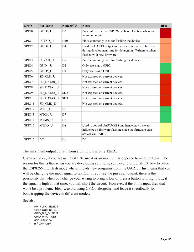
GPIO Pin Name NodeMCU Notes Risk
GPIO0 GPIO0_U D3 Pin controls state of ESP8266 at boot. Caution when used as an output pin.
GPIO1 U0TXD_U D10 Pin is commonly used for flashing the device.
GPIO2 GPIO2_U D4 Used for UART1 output and, as such, is likely to be used during development time for debugging. Written to when flashed with new firmware.
GPIO3 U0RXD_U D9 Pin is commonly used for flashing the device.
GPIO4 GPIO4_U D2 Only use is as a GPIO.
GPIO5 GPIO5_U D1 Only use is as a GPIO.
GPIO6 SD_CLK_U Not exposed on current devices.
GPIO7 SD_DATA0_U Not exposed on current devices.
GPIO8 SD_DATA1_U Not exposed on current devices.
GPIO9 SD_DATA2_U SD2 Not exposed on current devices.
GPIO10 SD_DATA3_U SD3 Not exposed on current devices.
GPIO11 SD_CMD_U Not exposed on current devices.
GPIO12 MTDI_U D6
GPIO13 MTCK_U D7
GPIO14 MTMS_U D5
GPIO15 MTDO_U D8 Used to control UART0 RTS and hence may have an influence on firmware flashing since the firmware data arrives via UART0.
GPIO16 ??? D0 ???
The maximum output current from a GPIO pin is only 12mA.
Given a choice, if you are using GPIO0, use it as an input pin as opposed to an output pin. The reason for this is that when you are developing solutions, you need to bring GPIO0 low to place the ESP8266 into flash mode where it reads new programs from the UART. This means that youwill be changing the input signal to GPIO0. If you use the pin as an output, there is the possibility that when you change your wiring to bring it low or press a button to bring it low, if the signal is high at that time, you will short the circuit. However, if the pin is input then that won't be a problem. Ideally, avoid using GPIO0 altogether and leave it specifically for bootstrapping the device in different modes.
See also:
• PIN_FUNC_SELECT• GPIO_OUTPUT_SET• GPIO_DIS_OUTPUT• GPIO_INPUT_GET• gpio_output_set• gpio_input_get
Page 115

Pullup and pull down settingsWe commonly think of an input GPIO pin as having either a high or low signal supplied to it. This means that it is connected to +ve or ground. But what if it is connected to neither? In this case, the pin is considered to be in a floating state. There are times where we wish to defined an unconnected pin as being high or low. An unconnected pin that is to be considered high is termed "pulled up" while an unconnected pin that is to be considered low is termed "pulldown". This comes from the physical hardware practice of attaching resistors to pull up or pull down the signal when it otherwise would be floating.
In the ESP8266 SDK, we can define a GPIO as being pulled-up by using the macro called PIN_PULLUP_EN and we can define the GPIO as no longer being pulled up using the macro PIN_PULLUP_DIS.
GPIO Interrupt handlingIf we consider that the signal on a pin can move from high to low or from low to high, such a change might be something our application would be interested in knowing. To determine when such a change happens, we can continually poll the value and detect a transition change. However this in not the best solution for a number of reasons. First, we have to busily perfom working checking whether a value has changed. Secondly, there will be a latency from the time the event happens to the time when we check. Thirdly, it is possible to completely miss a signal change if the duration of the change is short. For example, if we check the value of a pin and find it high and then immediately after it goes low and then high again, the next time we poll we will still see the pin high and never have known that it was ever low for a short period.
The solution to all these problems is the notion of an interrupt. An interrupt is similar to your doorbell at your house. Without a door bell (or listening for someone knocking) you would have to periodically check to see if there is anyone at the door. This wastes your time for the majority of instances where there is no-one there and also makes sure that when there is someone there, you attend to them in a timely fashion.
In the land of ESP8266s, we can define an interrupt callback function that will be called when a pin changes its signal value. We can also define what constitutes a reason for invoking the callback. We can configure the callback handler (technically called an interrupt handler) on a pinby pin basis.
First, let us consider the interrupt callback function. This is registered with a call to gpio_intr_handler_register().
We can enable or disable interrupt handling on a global level. A call to ETS_GPIO_INTR_ENABLE enables interrupt handling while a call to ETS_GPIO_INTR_DISABLE disables global interrupt handling.
Page 116
To enable an interrupt for a specific pin, we use the function called gpio_pin_intr_state_set(). This allows us to set the reason that an interrupt might occur. The reasons include:
• Disable – don't call an interrupt on a signal change.
• PosEdge – Call the interrupt handler on a change from low to high.
• NegEdge – Call the interrupt handler on a change from high to low.
• AnyEdge – Call the interrupt handler on either a change from low to high or a change from high to low.
• Hi – Call the interrupt handler while the signal is high.
• Lo – Call the interrupt handler while the signal is low.
Notes: When I went to implement an interrupt handler in a project, I found that theory and practice didn't meet. As of now, the only story I have got working for an interrupt handler looks as follows:
static void intrHandlerCB( uint32 interruptMask, //!< A mask indicating which GPIOs have changed. void *arg //!< Optional argument. ) uint32 gpio_status = GPIO_REG_READ(GPIO_STATUS_ADDRESS); os_printf("status: 0x%x\n", gpio_status); gpio_intr_ack(interruptMask); int pin; for (pin=0; pin<16; pin++) if ((interruptMask & (1<<pin)) != 0) // Do something gpio_pin_intr_state_set(GPIO_ID_PIN(pin), GPIO_PIN_INTR_ANYEDGE);
See also:
• gpio_intr_handler_register• gpio_pin_intr_state_set• gpio_intr_pending• gpio_intr_ack
Expanding the number of available GPIOsAlthough the ESP devices only have a limited number of GPIO pins, that needn't be a restriction for us. We have the capability to expand the number of GPIOs available to us through some relatively inexpensive integrated circuits. One of these is called the PCF8574. (The PFC8574A is the same but has a different set of addresses).
Page 117

This is an I2C device and hence works over only two wires. Using this IC we supply a 3 bit address (000-111) that is used to select the slave address of the device. Since each address has 8 IOs and we can have up to 8 devices, this means a total of 64 additional pins.
It appears that the device will use a pull-up resistor for a high and bring the pin to ground for low. This means that if we want to use any of the pins for input, we should set their write mode to high first. This will allow either a high or low input signal to be detected. It would appear that if we set the output signal to be low and then fed a raw high signal into the device, we wouldhave a short.
The mechanics of the device is that each instance has two addresses … one for reading and one for writing. If we issue a request to write to a device, it will write the byte to the corresponding pins. If you read from the read address, you will get back the instantaneous value found on the input.
Here is the pin diagram for the device:
Here is a description of the pins:
Symbol Pin Description
A0-A2 1, 2, 3 Addressing
P0-P7 4, 5, 6, 7, 9, 10, 11, 12 Bi directional I/O
INT 13 Interrupt output
SCL 14 Serial Clock Line
SDA 15 Serial Data Line
VDD 16 Supply Voltage (2.5V – 6V)
Vss (Ground) 8 Ground
Page 118
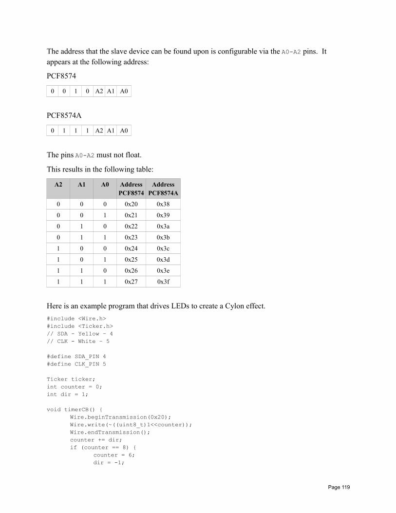
The address that the slave device can be found upon is configurable via the A0-A2 pins. It appears at the following address:
PCF8574
0 0 1 0 A2 A1 A0
PCF8574A
0 1 1 1 A2 A1 A0
The pins A0-A2 must not float.
This results in the following table:
A2 A1 A0 AddressPCF8574
AddressPCF8574A
0 0 0 0x20 0x38
0 0 1 0x21 0x39
0 1 0 0x22 0x3a
0 1 1 0x23 0x3b
1 0 0 0x24 0x3c
1 0 1 0x25 0x3d
1 1 0 0x26 0x3e
1 1 1 0x27 0x3f
Here is an example program that drives LEDs to create a Cylon effect.
#include <Wire.h>#include <Ticker.h>// SDA - Yellow – 4// CLK - White – 5
#define SDA_PIN 4#define CLK_PIN 5
Ticker ticker;int counter = 0;int dir = 1;
void timerCB() Wire.beginTransmission(0x20);Wire.write(~((uint8_t)1<<counter));Wire.endTransmission();counter += dir;if (counter == 8)
counter = 6;dir = -1;
Page 119
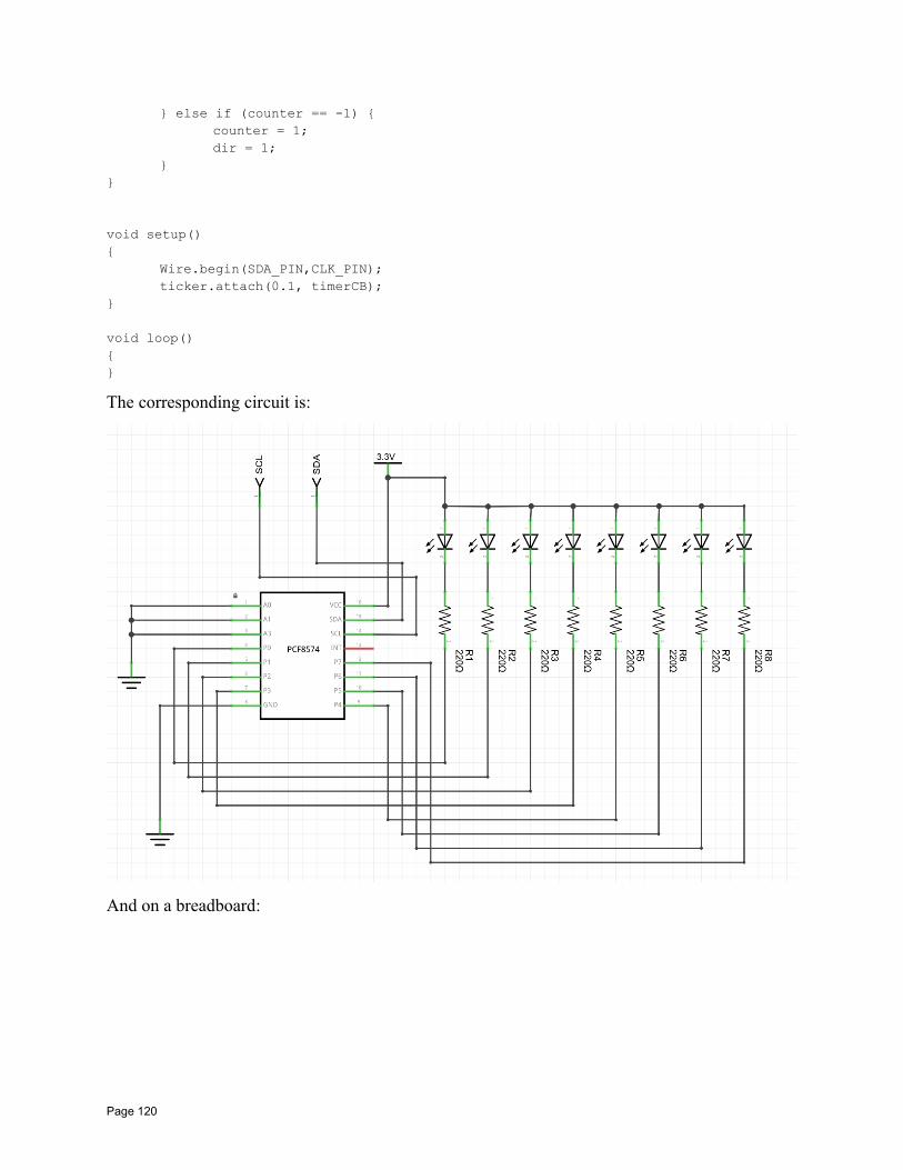
else if (counter == -1) counter = 1;dir = 1;
void setup()
Wire.begin(SDA_PIN,CLK_PIN);ticker.attach(0.1, timerCB);
void loop()
The corresponding circuit is:
And on a breadboard:
Page 120
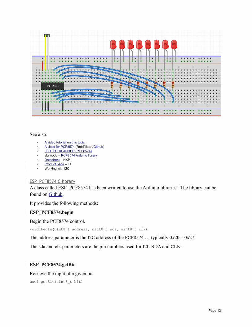
See also:
• A video tutorial on this topic• A class for PCF8574 (RobTillaart/Github)• 8BIT IO EXPANDER (PCF8574)• skywodd – PCF8574 Arduino library• Datasheet – NXP• Product page – TI• Working with I2C
ESP_PCF8574 C libraryA class called ESP_PCF8574 has been written to use the Arduino libraries. The library can be found on Github.
It provides the following methods:
ESP_PCF8574.begin
Begin the PCF8574 control.
void begin(uint8_t address, uint8_t sda, uint8_t clk)
The address parameter is the I2C address of the PCF8574 … typically 0x20 – 0x27.
The sda and clk parameters are the pin numbers used for I2C SDA and CLK.
ESP_PCF8574.getBit
Retrieve the input of a given bit.
bool getBit(uint8_t bit)
Page 121
If we think of the 8 GPIOs supplied by the PCF8574 as being 8 bits of data, this method retrievesthe value of data on a given input pin.
ESP_PCF8574.getByte
Retrieve all 8 bits of input.
uint8_t getByte()
If we think of the 8 GPIOs supplied by the PCF8574 as being 8 bits of data, this method retrievesthe value of all the inputs.
ESP_PCF8574.setBit
Set the value of a given output pin.
void setBit(uint8_t bit, bool value)
Set the value of a given output pin.
ESP_PCF8574.setByte
Set the value of all output pins.
void setByte(uint8_t value)
Set the value of all output pins.
PCF8574 JavaScript Library
A JavaScript library has been built for interfacing the PCF8574 from a JavaScript application.
Working with I2CThe I2C interface is a serial interface technology for accessing devices. It has two signal lines called SDA (Data) and SCL (Clock). The ESP8266 can act as a master and the devices connected downstream act as slaves. Up to 127 distinct slaves are theoretically attachable. Eachslave device has a unique address and the master decides which slave is to receive data or be allowed to speak next.
All the slaves connected use an "open drain" connection to the bus. This means that when they connect, their attachment is either open circuit or ground as an output. Because of this it is impossible for there to be an electrical conflict as it would be impossible for one device to assert a high signal while another tried to assert a low signal. The presence of a logical high signal
Page 122

occurs when the current slave device goes open circuit. This means that we need pull-up resistors on the lines such that when no-one is actively asserting a low signal, they are pulled-up to a logical high signal. A resistor value of 4.7KΩ is recommended.
The start of a transmission is indicated when the SCL is left high and SDA is pulled low. This informs all the slave devices that an address is about to be issued. When the address is seen by all the slaves, only one of them should match and the other devices ignore the request.
The address of a slave follows the initial start indication and is comprised of 7 bits with most significant bit first. Following the 7 bit address is a final 8th bit that indicates whether this is a read or a write request. A value of 1 indicates a read from the slave while a value of 0 indicates awrite from the master.
Immediately after the 8 bits of address, comes the acknowledgment bit. This bit is not transmitted from the master to the slave but is instead transmitted from the slave to the master. Be sure you understand that as when looking at diagrams showing data on the SDA wire, those diagrams typically do not show the origination of the data, only their sequence. The turn around time from the last bit of the 8 bit address/direction data sent from the master to the acknowledgment bit sent from the slave happens without missing any clock cycles so has to be fast. A value of 0 in the acknowledgment states that the slave will process or respond. A value of 1 in the acknowledgment states that no-one is responding or the slave is not present.
Following this addressing frame comes the data frame or frames. For a master write request, the master will send 8 bits of data and expect a single bit of acknowledgment. For a read from the slave, the slave will send 9 bits of data (8 data bits and an acknowledgment).
The master will finally send an end of communication (or stop) indication which is a transition tohigh on the clock with NO corresponding transition to low and then a transition from low to highon the SDA line.
To use I2C, we first transmit a start request using i2c_master_start(). We follow this by the address and the read/write flag. Since an address is 7 bits and the read/write flag is one bit, this totals 8 bits and hence we can write a byte:
i2c_master_writeByte((address << 1) | readOrWrite);
Next we can read and check the acknowledgment flag using:
if (i2c_master_checkAck() == true) ...
And from here we can either end or execute the next part of read or write.
When we wish to end, we execute i2c_master_stop().
We can send an address query for each of the possible device addresses and see if we get an acknowledgment. If we do, then we have an I2C device at that address. This can be used to create a map of devices.
Page 123
Here is an example application that does just that:
#include <ets_sys.h>#include <osapi.h>#include <os_type.h>#include <gpio.h>#include <user_interface.h>#include <espconn.h>#include <mem.h>#include "driver/uart.h"#include "driver/i2c_master.h"
void user_rf_pre_init(void)
os_timer_t scanTimer;
void scanTimerCB(void *pArg) os_printf("--- Examining ---\n");uint8_t i;for (i=1; i<127; i++)
i2c_master_start();i2c_master_writeByte(i << 1);
if (i2c_master_checkAck()) os_printf("Found device at: 0x%2x\n", i);
i2c_master_stop();
os_printf("Done!\n");
// End of timerCallback
void init() i2c_master_gpio_init();os_timer_setfn(&scanTimer, scanTimerCB, NULL);os_timer_arm(&scanTimer, 10000, 1);
void user_init(void) uart_init(BIT_RATE_115200, BIT_RATE_115200);system_init_done_cb(init);
// End of user_init
See also:
• I2C Bus• Sparkfun – Tutorial: I2C• I2C Master APIs
Working with SPI – Serial Peripheral InterfaceSPI is a serial protocol used to communicate between masters and slaves. All slaves connect to the same bus but only the slave with its SS pin low is allowed to transmit. SPI is a full duplex
Page 124

protocol. What this means is that while data is being pushed out from the master to the slave, theslave is simultaneously sending data back to the master. The MOSI pin contains the serial data from the master to the slave while the MISO pin contains the data from the slave to the master.
Typically three pins:
MISO – Master In, Slave Out – Sending data to the master from the slave
MOSI – Master Out, Slave In – Sending data to the slave from the master
SCK (SCLK) – Serial Clock – Synchronizes data from the master/slave relationship
There is also an additional signal:
SS (CSN (Chip Select NOT), NSS) – Slave Select – Used to enable/disable the slave so that there can be multiple slaves. SS low means slave is the active slave.
Since this is a serial protocol and we will receive data in bytes, we need to be cognizant of whether or not data will arrive LSB first or MSB first. There will be an option to control this.
For the clock, we will be latching data and we will need to know what edges and settings are important. There will be a clock mode option to control this. In SPI there are two attributes called phase and polarity. Phase (CPHA) is whether we are latching data on high or low and
Polarity (CPOL) is whether high or low means that the clock is idle.
CPOL=0 means clock is default low, CPOL=1 means clock is default high.
When CPOL=0, then the following are the values for CPHA
CPHA=0 means data is captured on clock rising edge, CPHA=1 means data is captured on clock falling edge.
When CPOL=1, then the following are the values for CPHA
CPHA=0 means data is captured on clock falling edge, CPHA=1 means data is captured on clock rising edge.
SPI wraps these two flags into four defined and named modes:
Mode Clock Polarity – CPOL Clock Phase – CPHA
SPI_MODE0 0 (Clock default low) 0
SPI_MODE1 0 (Clock default low) 1
SPI_MODE2 1 (Clock default high) 0
SPI_MODE3 1 (Clock default high) 1
Page 125
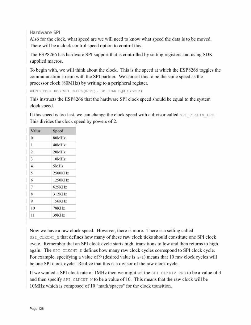
Hardware SPIAlso for the clock, what speed are we will need to know what speed the data is to be moved. There will be a clock control speed option to control this.
The ESP8266 has hardware SPI support that is controlled by setting registers and using SDK supplied macros.
To begin with, we will think about the clock. This is the speed at which the ESP8266 toggles thecommunication stream with the SPI partner. We can set this to be the same speed as the processor clock (80MHz) by writing to a peripheral register.
WRITE_PERI_REG(SPI_CLOCK(HSPI), SPI_CLK_EQU_SYSCLK)
This instructs the ESP8266 that the hardware SPI clock speed should be equal to the system clock speed.
If this speed is too fast, we can change the clock speed with a divisor called SPI_CLKDIV_PRE. This divides the clock speed by powers of 2.
Value Speed
0 80MHz
1 40MHz
2 20MHz
3 10MHz
4 5MHz
5 2500KHz
6 1250KHz
7 625KHz
8 312KHz
9 156KHz
10 78KHz
11 39KHz
Now we have a raw clock speed. However, there is more. There is a setting called SPI_CLKCNT_N that defines how many of these raw clock ticks should constitute one SPI clock cycle. Remember that an SPI clock cycle starts high, transitions to low and then returns to high again. The SPI_CLKCNT_N defines how many raw clock cycles correspond to SPI clock cycle. For example, specifying a value of 9 (desired value is n+1) means that 10 raw clock cycles will be one SPI clock cycle. Realize that this is a divisor of the raw clock cycle.
If we wanted a SPI clock rate of 1MHz then we might set the SPI_CLKDIV_PRE to be a value of 3and then specify SPI_CLKCNT_N to be a value of 10. This means that the raw clock will be 10MHz which is composed of 10 "mark/spaces" for the clock transition.
Page 126
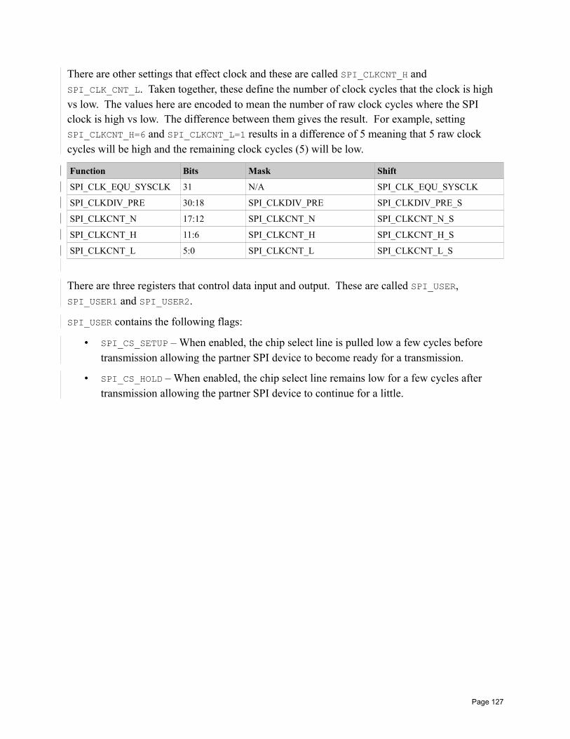
There are other settings that effect clock and these are called SPI_CLKCNT_H and SPI_CLK_CNT_L. Taken together, these define the number of clock cycles that the clock is high vs low. The values here are encoded to mean the number of raw clock cycles where the SPI clock is high vs low. The difference between them gives the result. For example, setting SPI_CLKCNT_H=6 and SPI_CLKCNT_L=1 results in a difference of 5 meaning that 5 raw clock cycles will be high and the remaining clock cycles (5) will be low.
Function Bits Mask Shift
SPI_CLK_EQU_SYSCLK 31 N/A SPI_CLK_EQU_SYSCLK
SPI_CLKDIV_PRE 30:18 SPI_CLKDIV_PRE SPI_CLKDIV_PRE_S
SPI_CLKCNT_N 17:12 SPI_CLKCNT_N SPI_CLKCNT_N_S
SPI_CLKCNT_H 11:6 SPI_CLKCNT_H SPI_CLKCNT_H_S
SPI_CLKCNT_L 5:0 SPI_CLKCNT_L SPI_CLKCNT_L_S
There are three registers that control data input and output. These are called SPI_USER, SPI_USER1 and SPI_USER2.
SPI_USER contains the following flags:
• SPI_CS_SETUP – When enabled, the chip select line is pulled low a few cycles before transmission allowing the partner SPI device to become ready for a transmission.
• SPI_CS_HOLD – When enabled, the chip select line remains low for a few cycles after transmission allowing the partner SPI device to continue for a little.
Page 127
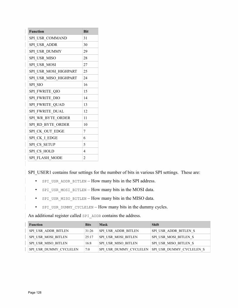
Function Bit
SPI_USR_COMMAND 31
SPI_USR_ADDR 30
SPI_USR_DUMMY 29
SPI_USR_MISO 28
SPI_USR_MOSI 27
SPI_USR_MOSI_HIGHPART 25
SPI_USR_MISO_HIGHPART 24
SPI_SIO 16
SPI_FWRITE_QIO 15
SPI_FWRITE_DIO 14
SPI_FWRITE_QUAD 13
SPI_FWRITE_DUAL 12
SPI_WR_BYTE_ORDER 11
SPI_RD_BYTE_ORDER 10
SPI_CK_OUT_EDGE 7
SPI_CK_I_EDGE 6
SPI_CS_SETUP 5
SPI_CS_HOLD 4
SPI_FLASH_MODE 2
SPI_USER1 contains four settings for the number of bits in various SPI settings. These are:
• SPI_USR_ADDR_BITLEN – How many bits in the SPI address.
• SPI_USR_MOSI_BITLEN – How many bits in the MOSI data.
• SPI_USR_MISO_BITLEN – How many bits in the MISO data.
• SPI_USR_DUMMY_CYCLELEN – How many bits in the dummy cycles.
An additional register called SPI_ADDR contains the address.
Function Bits Mask Shift
SPI_USR_ADDR_BITLEN 31:26 SPI_USR_ADDR_BITLEN SPI_USR_ADDR_BITLEN_S
SPI_USR_MOSI_BITLEN 25:17 SPI_USR_MOSI_BITLEN SPI_USR_MOSI_BITLEN_S
SPI_USR_MISO_BITLEN 16:8 SPI_USR_MISO_BITLEN SPI_USR_MISO_BITLEN_S
SPI_USR_DUMMY_CYCLELEN 7:0 SPI_USR_DUMMY_CYCLELEN SPI_USR_DUMMY_CYCLELEN_S
Page 128
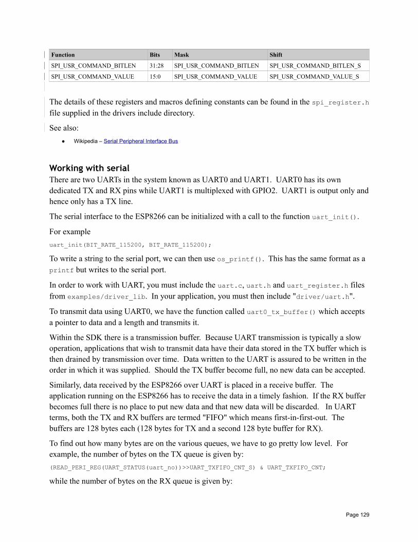
Function Bits Mask Shift
SPI_USR_COMMAND_BITLEN 31:28 SPI_USR_COMMAND_BITLEN SPI_USR_COMMAND_BITLEN_S
SPI_USR_COMMAND_VALUE 15:0 SPI_USR_COMMAND_VALUE SPI_USR_COMMAND_VALUE_S
The details of these registers and macros defining constants can be found in the spi_register.hfile supplied in the drivers include directory.
See also:
Wikipedia – Serial Peripheral Interface Bus
Working with serialThere are two UARTs in the system known as UART0 and UART1. UART0 has its own dedicated TX and RX pins while UART1 is multiplexed with GPIO2. UART1 is output only andhence only has a TX line.
The serial interface to the ESP8266 can be initialized with a call to the function uart_init().
For example
uart_init(BIT_RATE_115200, BIT_RATE_115200);
To write a string to the serial port, we can then use os_printf(). This has the same format as a printf but writes to the serial port.
In order to work with UART, you must include the uart.c, uart.h and uart_register.h files from examples/driver_lib. In your application, you must then include "driver/uart.h".
To transmit data using UART0, we have the function called uart0_tx_buffer() which accepts a pointer to data and a length and transmits it.
Within the SDK there is a transmission buffer. Because UART transmission is typically a slow operation, applications that wish to transmit data have their data stored in the TX buffer which is then drained by transmission over time. Data written to the UART is assured to be written in the order in which it was supplied. Should the TX buffer become full, no new data can be accepted.
Similarly, data received by the ESP8266 over UART is placed in a receive buffer. The application running on the ESP8266 has to receive the data in a timely fashion. If the RX buffer becomes full there is no place to put new data and that new data will be discarded. In UART terms, both the TX and RX buffers are termed "FIFO" which means first-in-first-out. The buffers are 128 bytes each (128 bytes for TX and a second 128 byte buffer for RX).
To find out how many bytes are on the various queues, we have to go pretty low level. For example, the number of bytes on the TX queue is given by:
(READ_PERI_REG(UART_STATUS(uart_no))>>UART_TXFIFO_CNT_S) & UART_TXFIFO_CNT;
while the number of bytes on the RX queue is given by:
Page 129
(READ_PERI_REG(UART_STATUS(UART0))>>UART_RXFIFO_CNT_S) & UART_RXFIFO_CNT;
See also:
• Connecting to the ESP8266• USB to UART converters• uart_init• uart0_tx_buffer• uart0_rx_intr_handler• os_printf
Task handlingImagine we wish to have a task performed for us asynchronously. What we might want to do is post that we wish this to happen and then go on with our business. When we are done and have relinquished control back to the OS, we assume that the task will eventually start executing. Thisis the function provided by the task functions of the ESP8266. There are two functions of interest to us. The first is called system_os_task() which sets up a task processor.
When we wish to post that a task is eligible to start, we can use the second function called system_os_post() which posts a message.
The task function that we registered will then be "invoked" at some point after the post request and will be given the parameters supplied in the post. The priority identifies the relative priority of two posts that have been issued. The one with the highest priority will execute first.
It is important to note that only three priorities are allowed which are 0, 1 and 2 with 0 having the lowest priority. It is also important to note that there can only be one handler for each task registration by priority. So if we execute system_os_task() twice using the same priority in both cases, only the last one is remembered and will be executed when a task of that priority is posted.
With this background, what is the purpose of this function set? Why would we care about it?
Note: The Arduino library for ESP uses the priority 0 task set.
Here is a sample of a simple task handler.
void taskHandler(os_event_t *event) switch(event->sig) case 1:
break;case 2:
break;
os_event_t *taskQueue;taskQueue = (os_event_t *)malloc(sizeof(os_event_t) * TASK_QUEUE_LEN);system_os_task(taskHandler, USER_TASK_PRIO_1 taskQueue, TASK_QUEUE_LEN);
system_os_post(USER_TASK_PRIO_1, 1, (os_param_t)"Hello");
Page 130
See also:
• system_os_task• system_os_post
Timers and timeWithin our code, we may wish to delay for a period of time. We can use the os_delay_us() function to suspend processing for a given period measured in microseconds. There are 1000 microseconds in a millisecond and a 1000 milliseconds in a second.
We can configure a timer to be called on a periodic basis with a callback granularity of milliseconds. A data structure called os_timer_t holds the state of the timer.
We can define the user function to be called when the timer fires using the os_timer_setfn() function. Note that we can only set the callback function when the timer is disarmed.
When ready, we can arm the timer so that it starts ticking and fires when ready. We do this usingthe os_timer_arm() function.
The repeat flag indicates whether the timer should restart after it has fired.
We can suspend or cancel the firing of the timer using os_timer_disarm().
Here is an example:
os_timer_t myTimer;
void timerCallback(void *pArg) os_printf("Tick!);
// End of timerCallback
void user_init(void) uart_init(BIT_RATE_115200, BIT_RATE_115200);os_timer_setfn(&myTimer, timerCallback, NULL);os_timer_arm(&myTimer, 1000, 1);
// End of user_init
Another aspect of working with time is time calculations and measurement. The function system_get_time() returns a 32 bit unsigned integer (unit32) value which is the microseconds since the device booted. This value will roll over after 71 minutes.
We can also explicitly block execution for a period of time using os_delay_us().
See also:
• system_get_time• os_timer_arm• os_timer_disarm• os_timer_setfn
Page 131
Working with memoryWhen working in C, you have to think in terms of computer memory. With great power comes great responsibility. The amount of available RAM is likely to be less than 45KBytes.
We can allocate memory using os_malloc() or os_zalloc(). The first function allocates and returns memory and the second does exactly the same but zeros the memory before returning. When your logic no longer needs the memory, it can return it back to the heap with os_free(). To determine how much heap size is available, we can call system_get_free_heap_size(). Once we have the memory pointer, we can start to manipulate it through a series of memory commands. The os_memset() command will set a block of memory to a specific value. The os_memcpy() will copy a block of memory to a different block. The os_bzero() function will set the values of a block of memory to zero.
Memory on the ESP8266 is made up of a number of components. We have:
• data
• rodata
• bss
• heap
The values of these can be found through the system_print_meminfo() function.
When the ESP8266 needs to read an instruction from memory in order to execute it, that instruction can come from one of two places. The instruction can in flash memory (also called irom) or it can be in RAM (also called iram). It takes less time for the processor to retrieve the instruction from RAM than it does from flash. It is believed that an instruction fetch from flash takes four times longer than the same instruction fetched from RAM. However, on the ESP8266 there is far less RAM than there is flash. What this means is that you are far more likely to run out of RAM way before you run out of flash. When writing normal applications, we shouldn't fixate on having instructions in RAM rather than flash for the performance benefit. The execution speeds of the ESP8266 are so fast that if the cost of retrieving an instruction from RAM is blindingly fast then retrieving an instruction from slower flash is still blindingly fast.
There are however certain classes of instructions that we might wish to place in RAM rather thanflash. Examples of these are interrupt handlers where the time spent in these should always be asfast as possible and also function that write to flash.
When we define C functions, we can add an attribute by the name of ICACHE_FLASH_ATTR. What this does is place this function in the flash memory address space as opposed to RAM. Specifically, flagging a function with ICACHE_FLASH_ATTR tags it as being in the ".text" sectionof code.
One of the areas we have not yet discussed is how memory is populated and used when an ESP8266 boots. There are two files commonly uploaded into flash. The first is at offset
Page 132
0x00000 and this contains the data that will be loaded into RAM by the ROM based boot-loader. This data contains a series of sections and addresses in RAM of where the data will be loaded. The second binary file is commonly loaded into flash at 0x40000. It contains the binary data of asection called .irom0 which contains code. The RAM loaded code must match where this flash stored data is addressed.
For those interested in low level details, the format of the memory written to the flash files has been decoded. It is believed that the low memory looks like:
struct rom_header uint8 magic;uint8 sect_count;uint8 flags1;uint8 flags2;uint32 entry_addr;
;
The magic property is a constant of 0xe9. The sect_count contains the number of sections to load into ram. This will not include the irom.text section. The flags1 and flags2 are used to indicate the flash size, clock rate and IO mode. Finally, entry_addr is the entry point to start executing user supplied code.
Immediately following the header, are section entries (there should be sect_count of them) whereeach entry is:
struct sect_header uint32 address;uint32 length;
The addresses should be within the .iram address space starting at 0x40100000. After each of the headers is a check-sum value. A check-sum is calculated from each of the sections and validated that it matches what is supposed to be present.
The whole of flash is also mapped to address space 0x40200000.
The second file contains the irom.text section data. By default, the address space for this section is 0x40240000 which means that it should be written to flash at 0x40000.
An excellent map of ESP8266 memory is being maintained on the ESP8266 Wiki.
The core essence of it is here:
Page 133
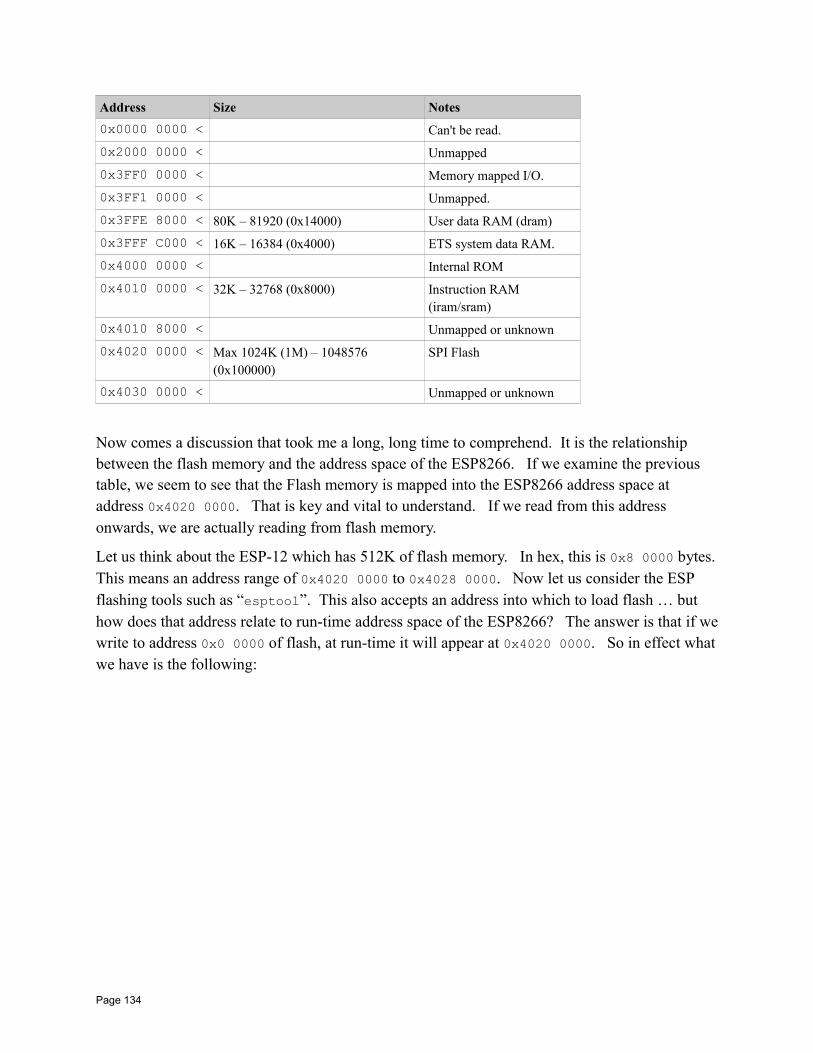
Address Size Notes
0x0000 0000 < Can't be read.
0x2000 0000 < Unmapped
0x3FF0 0000 < Memory mapped I/O.
0x3FF1 0000 < Unmapped.
0x3FFE 8000 < 80K – 81920 (0x14000) User data RAM (dram)
0x3FFF C000 < 16K – 16384 (0x4000) ETS system data RAM.
0x4000 0000 < Internal ROM
0x4010 0000 < 32K – 32768 (0x8000) Instruction RAM (iram/sram)
0x4010 8000 < Unmapped or unknown
0x4020 0000 < Max 1024K (1M) – 1048576 (0x100000)
SPI Flash
0x4030 0000 < Unmapped or unknown
Now comes a discussion that took me a long, long time to comprehend. It is the relationship between the flash memory and the address space of the ESP8266. If we examine the previous table, we seem to see that the Flash memory is mapped into the ESP8266 address space at address 0x4020 0000. That is key and vital to understand. If we read from this address onwards, we are actually reading from flash memory.
Let us think about the ESP-12 which has 512K of flash memory. In hex, this is 0x8 0000 bytes.This means an address range of 0x4020 0000 to 0x4028 0000. Now let us consider the ESP flashing tools such as “esptool”. This also accepts an address into which to load flash … but how does that address relate to run-time address space of the ESP8266? The answer is that if wewrite to address 0x0 0000 of flash, at run-time it will appear at 0x4020 0000. So in effect whatwe have is the following:
Page 134
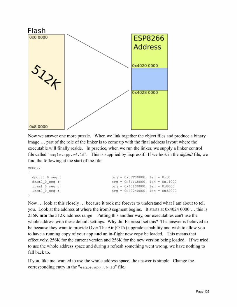
Now we answer one more puzzle. When we link together the object files and produce a binary image … part of the role of the linker is to come up with the final address layout where the executable will finally reside. In practice, when we run the linker, we supply a linker control file called "eagle.app.v6.ld". This is supplied by Espressif. If we look in the default file, we find the following at the start of the file:
MEMORY dport0_0_seg : org = 0x3FF00000, len = 0x10 dram0_0_seg : org = 0x3FFE8000, len = 0x14000 iram1_0_seg : org = 0x40100000, len = 0x8000 irom0_0_seg : org = 0x40240000, len = 0x32000
Now … look at this closely … because it took me forever to understand what I am about to tell you. Look at the address at where the irom0 segment begins. It starts at 0x4024 0000 … this is 256K into the 512K address range! Putting this another way, our executables can't use the whole address with these default settings. Why did Espressif set this? The answer is believed to be because they want to provide Over The Air (OTA) upgrade capability and wish to allow you to have a running copy of your app and an in-flight new copy be loaded. This means that effectively, 256K for the current version and 256K for the new version being loaded. If we triedto use the whole address space and during a refresh something went wrong, we have nothing to fall back to.
If you, like me, wanted to use the whole address space, the answer is simple. Change the corresponding entry in the "eagle.app.v6.ld" file.
Page 135
One last wrinkle. It is believed that the last 16K of flash should be reserved for Espressif SDK storage for things like the last used SSID and password. Don't assume that you can use that range.
See also:
• os_memset• os_memcpy• os_memcmp• os_malloc• os_zalloc• os_free• system_get_free_heap_size• system_print_meminfo• The ESP8266 Boot Process• esptool.py• esptool-ck• gen_appbin.py
Working with flash memoryFlash memory provides a non-volatile repository of information that survives a power cycle of the device.
Data contained within flash is stored in units of sectors which are 4096 bytes in size. To write data we can call spi_flash_write. To read data we call spi_flash_read.
Since writing to flash is performed in units of 4096 bytes, we can not change a single byte by justover-writing it, instead we must retrieve the whole sector, erase the sector and then write back the sector with the changed content. This can take some time to complete and because of this, we may find that a failure is more likely to occur (eg. a loss of power). If a failure occurs after we have erased a sector or during the re-write of the sector, it should immediately become apparent that we will result in an overall corruption of data.
See also:
• spi_flash_get_id• spi_flash_erase_sector• spi_flash_write• spi_flash_read• spi_flash_set_read_func• system_param_save_with_protect
Page 136

• system_param_load
Pulse Width Modulation – PWMThe idea behind pulse width modulation is that we can think of regular pulses of output signals encoding information as a function of how long the signal is kept high. Let us imagine that we have a period of 1HZ (one thing per second). Now let us assume that we raise the output voltageto a level of 1 for ½ of a second at the start of the period. This would give us a square wave which starts high, lasts for 500 milliseconds and then drops low for the next 500 milliseconds. This repeats on into the future. The duration that the pulse is high relative to the period allows usto encode an analog value onto digital signals. If the pulse is 100% high for the period then the encoded value would be 1.0. If the pulse is 100% low for the period, then the encoded value would be 0.0. If the pulse is on for "n" milliseconds (where n is less than 1000), then the encoded value would be n/1000.
Typically, the length of a period is not a second but much, much smaller allowing us to output many differing values very quickly. The ratio of the on signal to the period is called the "duty cycle". This encoding technique is called "Pulse Width Modulation" or "PWM".
There are a variety of purposes for PWM. Some are output data encoders. One commonly seen purpose is to control the brightness of an LED. If we apply maximum voltage to an LED, it is maximally bright. If we apply ½ the voltage, it is about ½ the brightness. By applying a fast period PWM signal to the input of an LED, the duty cycle becomes the brightness of the LED. The way this works is that either full voltage or no voltage is applied to the LED but because the period is so short, the "average" voltage over time follows the duty cycle and even though the LED is flickering on or off, it is so fast that our eyes can't detect it and all we see is the apparent brightness change.
For the ESP8266, the period of the PWM can range from 1 millisecond to 10 milliseconds. This is a frequency of 1KHz to 100Hz. The resolution of the duty cycle is down to 45 nanoseconds which is 14 bits of resolution data. The device provides support for up to 8 PWM channels where each channel can be associated with its own pin and duty cycle. The period is the same for all PWM channels.
To start using the ESP8266 PWM support, a call to pwm_init() is needed which sets up which pins are to be used for PWM and for which channels. A call to this function also sets up an initial period and duty cycle. A call to pwm_start() can then be made to start the PWM outputs.The period of PWM as a whole and duty cycles for each channel can be changed using the pwm_set_period() and pwm_set_duty() functions.
See also:
• Wikipedia: Pulse-width modulation• pwm_init• pwm_start
pwm_set_duty• pwm_get_duty• pwm_set_period
Page 137

• pwm_get_period
Analog to digital conversionAnalog to digital conversion is the ability to read a voltage level from a pin between 0 and some maximum value and convert that analog voltage into a digital representation. Varying the voltage applied to the pin will change the value read. The ESP8266 has an analog to digital converter built into it with a resolution of 1024 distinct values. What that means is that 0 volts will produce a digital value of 0 while the maximum voltage will produce a digital value of 1023 and voltage ranges between these will produce a correspondingly scaled digital value.
To read the digital value of the analog voltage, the function called system_adc_read() should be called. The pin on the physical ESP8266 from which the voltage is read is called TOUT and serves no other purpose.
The input range on the pin is from 0V to 1V. This implies that the input voltage to the ADC can not be the maximum voltage used to power the ESP8266 itself (3.3V). So we will need to use a voltage divider circuit.
The formula to map these out is:
Vout=R2
R1+R2⋅Vin
Since we know Vout is going to 1V and Vin is 3V and we choose R2 to be 10K, we find:
R1=R2⋅VinVout
−R2
and for our values:
R1=10000∗3.3
1.0−10000=23000
A common 22K resistor will work well.
Here is an example. What this example does is print the value read from the ADC every second.
Page 138
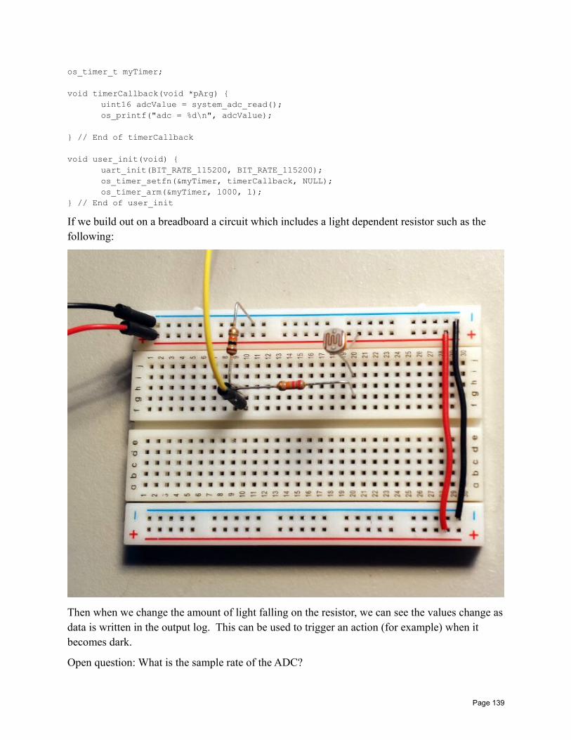
os_timer_t myTimer;
void timerCallback(void *pArg) uint16 adcValue = system_adc_read();os_printf("adc = %d\n", adcValue);
// End of timerCallback
void user_init(void) uart_init(BIT_RATE_115200, BIT_RATE_115200);os_timer_setfn(&myTimer, timerCallback, NULL);os_timer_arm(&myTimer, 1000, 1);
// End of user_init
If we build out on a breadboard a circuit which includes a light dependent resistor such as the following:
Then when we change the amount of light falling on the resistor, we can see the values change asdata is written in the output log. This can be used to trigger an action (for example) when it becomes dark.
Open question: What is the sample rate of the ADC?
Page 139
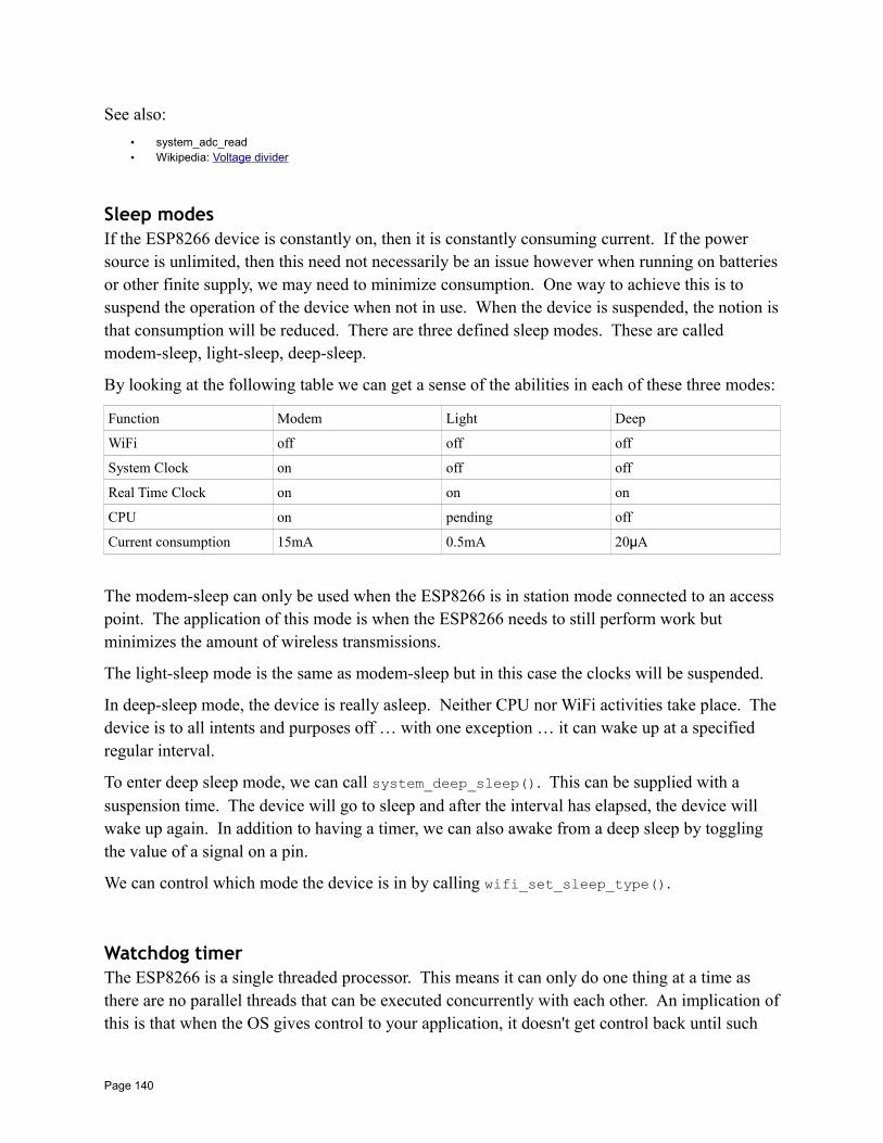
See also:
• system_adc_read• Wikipedia: Voltage divider
Sleep modesIf the ESP8266 device is constantly on, then it is constantly consuming current. If the power source is unlimited, then this need not necessarily be an issue however when running on batteriesor other finite supply, we may need to minimize consumption. One way to achieve this is to suspend the operation of the device when not in use. When the device is suspended, the notion isthat consumption will be reduced. There are three defined sleep modes. These are called modem-sleep, light-sleep, deep-sleep.
By looking at the following table we can get a sense of the abilities in each of these three modes:
Function Modem Light Deep
WiFi off off off
System Clock on off off
Real Time Clock on on on
CPU on pending off
Current consumption 15mA 0.5mA 20µA
The modem-sleep can only be used when the ESP8266 is in station mode connected to an access point. The application of this mode is when the ESP8266 needs to still perform work but minimizes the amount of wireless transmissions.
The light-sleep mode is the same as modem-sleep but in this case the clocks will be suspended.
In deep-sleep mode, the device is really asleep. Neither CPU nor WiFi activities take place. Thedevice is to all intents and purposes off … with one exception … it can wake up at a specified regular interval.
To enter deep sleep mode, we can call system_deep_sleep(). This can be supplied with a suspension time. The device will go to sleep and after the interval has elapsed, the device will wake up again. In addition to having a timer, we can also awake from a deep sleep by toggling the value of a signal on a pin.
We can control which mode the device is in by calling wifi_set_sleep_type().
Watchdog timerThe ESP8266 is a single threaded processor. This means it can only do one thing at a time as there are no parallel threads that can be executed concurrently with each other. An implication ofthis is that when the OS gives control to your application, it doesn't get control back until such
Page 140
time as you explicitly relinquish it. However, this can cause problems. The ESP8266 is primarily a WiFi and TCP/IP device that expects to be able to receive and transmit data as well asrespond to asynchronous events within a timely manner. As an example, if your ESP8266 deviceis connected to an access point and the access point wants to validate that you are still connected,it may transmit a packet to you and expect a response. You have no control over when that will happen. If your own application program has control over the execution at the time when the request arrives, that request will not be responded to until after you return control back to the OS.Meanwhile, the access point may be expecting a response within some predetermined time period and, if does not receive a reply within that interval, may assume that you have disconnected. To prevent such circumstances your application code has to return control back to the OS in a timely manner. It is recommended that your code return control within 50 milliseconds of gaining control. If you take longer, you run the risk of requests to your device timing out.
If your own code fails to return control back to the OS, the OS must assume that things are goingwrong. As such, it has a timer that we call the "watchdog". When control is given to your own code, the watchdog timer starts ticking. If you have not returned control back to the OS by the time the watchdog timer reaches zero, it takes matters into its own hands. Explicitly what it doesis reboot the device. This may sound like a pretty drastic action but the thinking is that it is better to do this and hope that whatever was blocked is now unblocked than just sit there "dead".
Reports claim that the watchdog timer may be about 1 second (1000 milliseconds). However, in my tests, I find that the timer fires at about 3.2 seconds (3200 msecs).
A function called system_soft_wdt_stop() stops the watchdog timer … or at least one of them. There appears to be two timers. One is in software, the other in hardware. This function stops the software timer. It can be restarted with system_soft_wdt_restart() … however, a second timer called the hardware watchdog timer will fire after about 8 seconds and doesn't appear able to be trapped. A new call introduced in SDK 1.3 is called system_soft_wdt_feed(). Unfortunately the documentation on this is exceedingly poor. The best reports we have so far on what it does for is that when we call it, the watchdog time is reset to its starting point and starts ticking down again. I'm not quite sure of the value of this given that we already have API to stop and then restart the timer. Hopefully in the future we can gain additional knowledge to clear up any mysteries that may be lurking within.
See also:
• system_soft_wdt_stop• system_soft_wdt_restart• system_soft_wdt_feed
Yielding controlWe have just been describing the notion of having to return control back to the OS in order for it to perform its house keeping duties. The way we do this is simply to return from the callback
Page 141
that the OS invoked us upon. If we think about how an ESP8266 program works, we will see that in order for us to relinquish control back to the OS, the OS must have called us in the first place. Therefore it makes sense for us to return control at a later point. However, if we return control, we (obviously) loose all the state (variables) that were in existence when we returned.
Now we get to introduce a concept called "yielding". The idea behind yielding is that instead of our application returning control back to the OS, what we can arrange to do is return to the OS while at the sametime maintaining the context of where we are within the current execution. When the OS completes a round of housekeeping, what it can then do is "return" back to where ever we were when we requested a yield to occur.
This is tricky stuff to implement but fortunately Ivan Gorkhotov has achieved this task for us andwe can leverage what he already built.
To use this:
1. Include cont.h
2. Create a global of "cont_t g_cont __attribute__ ((aligned (16)));"
3. In user_init called "cont_init(&g_cont);"
4. Register a system_os_task() processor.
When we wish to schedule some code for execution, post a task.
void esp_schedule() system_os_post(TASK_PRIORITY, 0, 0);
static void taskHandler(os_event_t *events) cont_run(&g_cont, someFunction); if(cont_check(&g_cont) != 0) os_printf("Overflow detected\r\n"); abort();
SecurityThe ESP8266 has the ability to store the password used to connect to the access point in memory.This means that if one were to physically compromise the device (i.e. steal it) then they could, in principle, dump the flash memory and retrieve your password. You could choose not to cache the password in the clear in flash but instead have your applications "decode" an encoded versionthat is saved in the flash memory … this would prevent an obvious retrieval through a simple memory grab. The encoding scheme could be a simple XOR against a magic number (either hard-coded or your own MAC address).
Page 142
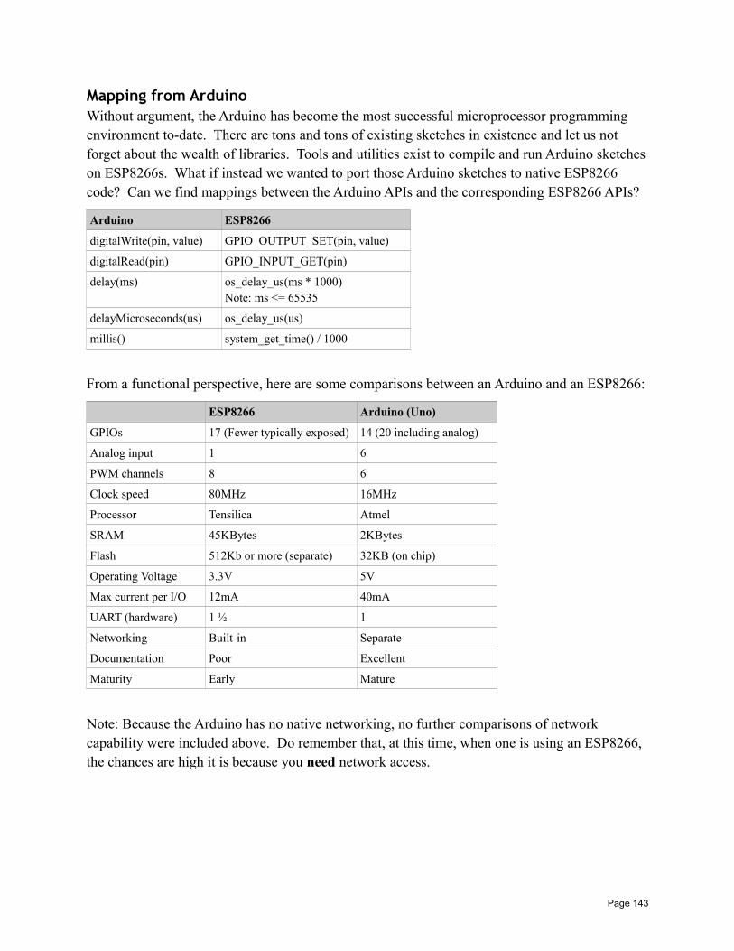
Mapping from ArduinoWithout argument, the Arduino has become the most successful microprocessor programming environment to-date. There are tons and tons of existing sketches in existence and let us not forget about the wealth of libraries. Tools and utilities exist to compile and run Arduino sketcheson ESP8266s. What if instead we wanted to port those Arduino sketches to native ESP8266 code? Can we find mappings between the Arduino APIs and the corresponding ESP8266 APIs?
Arduino ESP8266
digitalWrite(pin, value) GPIO_OUTPUT_SET(pin, value)
digitalRead(pin) GPIO_INPUT_GET(pin)
delay(ms) os_delay_us(ms * 1000)Note: ms <= 65535
delayMicroseconds(us) os_delay_us(us)
millis() system_get_time() / 1000
From a functional perspective, here are some comparisons between an Arduino and an ESP8266:
ESP8266 Arduino (Uno)
GPIOs 17 (Fewer typically exposed) 14 (20 including analog)
Analog input 1 6
PWM channels 8 6
Clock speed 80MHz 16MHz
Processor Tensilica Atmel
SRAM 45KBytes 2KBytes
Flash 512Kb or more (separate) 32KB (on chip)
Operating Voltage 3.3V 5V
Max current per I/O 12mA 40mA
UART (hardware) 1 ½ 1
Networking Built-in Separate
Documentation Poor Excellent
Maturity Early Mature
Note: Because the Arduino has no native networking, no further comparisons of network capability were included above. Do remember that, at this time, when one is using an ESP8266, the chances are high it is because you need network access.
Page 143
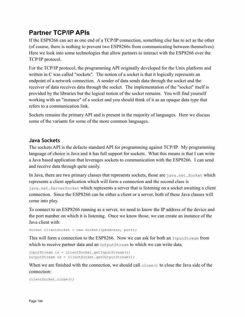
Partner TCP/IP APIsIf the ESP8266 can act as one end of a TCP/IP connection, something else has to act as the other (of course, there is nothing to prevent two ESP8266s from communicating between themselves). Here we look into some technologies that allow partners to interact with the ESP8266 over the TCP/IP protocol.
For the TCP/IP protocol, the programming API originally developed for the Unix platform and written in C was called "sockets". The notion of a socket is that it logically represents an endpoint of a network connection. A sender of data sends data through the socket and the receiver of data receives data through the socket. The implementation of the "socket" itself is provided by the libraries but the logical notion of the socket remains. You will find yourself working with an "instance" of a socket and you should think of it as an opaque data type that refers to a communication link.
Sockets remains the primary API and is present in the majority of languages. Here we discuss some of the variants for some of the more common languages.
Java SocketsThe sockets API is the defacto standard API for programming against TCP/IP. My programming language of choice is Java and it has full support for sockets. What this means is that I can write a Java based application that leverages sockets to communication with the ESP8266. I can send and receive data through quite easily.
In Java, there are two primary classes that represents sockets, those are java.net.Socket whichrepresents a client application which will form a connection and the second class is java.net.ServerSocket which represents a server that is listening on a socket awaiting a clientconnection. Since the ESP8266 can be either a client or a server, both of these Java classes will come into play.
To connect to an ESP8266 running as a server, we need to know the IP address of the device and the port number on which it is listening. Once we know those, we can create an instance of the Java client with:
Socket clientSocket = new Socket(ipAddress, port);
This will form a connection to the ESP8266. Now we can ask for both an InputStream from which to receive partner data and an OutputStream to which we can write data.
InputStream is = clientSocket.getInputStream();OutputStream os = clientSocket.getOutputStream();
When we are finished with the connection, we should call close() to close the Java side of the connection:
clientSocket.close();
Page 144
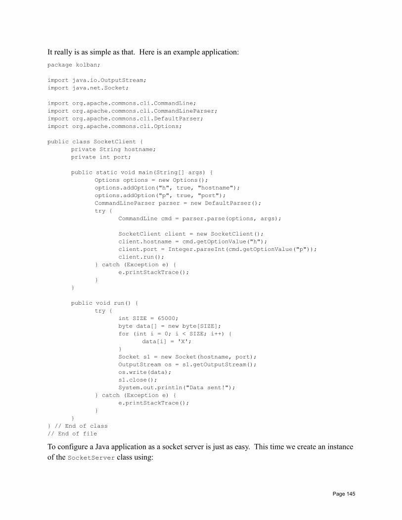
It really is as simple as that. Here is an example application:
package kolban;
import java.io.OutputStream;import java.net.Socket;
import org.apache.commons.cli.CommandLine;import org.apache.commons.cli.CommandLineParser;import org.apache.commons.cli.DefaultParser;import org.apache.commons.cli.Options;
public class SocketClient private String hostname;private int port;
public static void main(String[] args) Options options = new Options();options.addOption("h", true, "hostname");options.addOption("p", true, "port");CommandLineParser parser = new DefaultParser();try
CommandLine cmd = parser.parse(options, args);
SocketClient client = new SocketClient();client.hostname = cmd.getOptionValue("h");client.port = Integer.parseInt(cmd.getOptionValue("p"));client.run();
catch (Exception e) e.printStackTrace();
public void run() try
int SIZE = 65000;byte data[] = new byte[SIZE];for (int i = 0; i < SIZE; i++)
data[i] = 'X';Socket s1 = new Socket(hostname, port);OutputStream os = s1.getOutputStream();os.write(data);s1.close();System.out.println("Data sent!");
catch (Exception e) e.printStackTrace();
// End of class// End of file
To configure a Java application as a socket server is just as easy. This time we create an instanceof the SocketServer class using:
Page 145

SocketServer serverSocket = new SocketServer(port)
The port supplied is the port number on the machine on which the JVM is running that will be the endpoint of remote client connection requests. Once we have a ServerSocket instance, we need to wait for an incoming client connection. We do this using the blocking API method calledaccept().
Socket partnerSocket = serverSocket.accept();
This call blocks until a client connect arrives. The returned partnerSocket is the connected socket to the partner which can used in the same fashion as we previously discussed for client connections. This means that we can request the InputStream and OutputStream objects to read and write to and from the partner. Since Java is a multi-threaded language, once we wake up from accept() we can pass off the received partner socket to a new thread and repeat the accept() call for other parallel connections. Remember to close() any partner socket connections you receive when you are done with them.
So far, we have been talking about TCP oriented connections where once a connection is opened it stays open until closed during which time either end can send or receive independently from the other. Now we look at datagrams that use the UDP protocol.
The core class behind this is called DatagramSocket. Unlike TCP, the DatagramSocket class is used both for clients and servers.
First, let us look at a client. If we wish to write a Java UDP client, we will create an instance of aDatagramSocket using:
DatagramSocket clientSocket = new DatagramSocket();
Next we will "connect" to the remote UDP partner. We will need to know the IP address and portthat the partner is listening upon. Although the API is called "connect", we need to realize that no connection is formed. Datagrams are connectionless so what we are actually doing is associating our client socket with the partner socket on the other end so that when we actually wish to send data, we will know where to send it to.
clientSocket.connect(ipAddress, port);
Now we are ready to send a datagram using the send() method:
DatagramPacket data = new DatagramPacket(new byte[100], 100);clientSocket.send(data);
To write a UDP listener that listens for incoming datagrams, we can use the following:
DatagramSocket serverSocket = new DatagramSocket(port);
The port here is the port number on the same machine as the JVM that will be used to listen for incoming UDP connections.
To wait for an incoming datagram, call receive().
Page 146
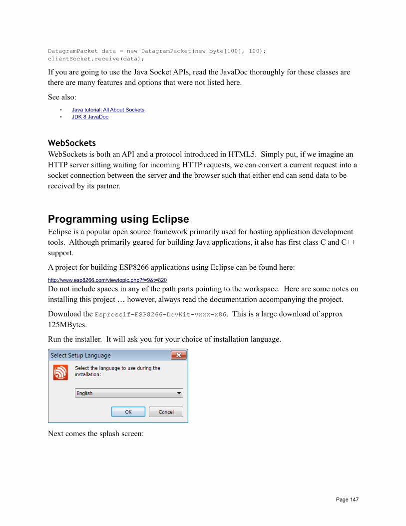
DatagramPacket data = new DatagramPacket(new byte[100], 100);clientSocket.receive(data);
If you are going to use the Java Socket APIs, read the JavaDoc thoroughly for these classes are there are many features and options that were not listed here.
See also:
• Java tutorial: All About Sockets• JDK 8 JavaDoc
WebSocketsWebSockets is both an API and a protocol introduced in HTML5. Simply put, if we imagine an HTTP server sitting waiting for incoming HTTP requests, we can convert a current request into asocket connection between the server and the browser such that either end can send data to be received by its partner.
Programming using EclipseEclipse is a popular open source framework primarily used for hosting application development tools. Although primarily geared for building Java applications, it also has first class C and C++ support.
A project for building ESP8266 applications using Eclipse can be found here:
http://www.esp8266.com/viewtopic.php?f=9&t=820
Do not include spaces in any of the path parts pointing to the workspace. Here are some notes oninstalling this project … however, always read the documentation accompanying the project.
Download the Espressif-ESP8266-DevKit-vxxx-x86. This is a large download of approx 125MBytes.
Run the installer. It will ask you for your choice of installation language.
Next comes the splash screen:
Page 147
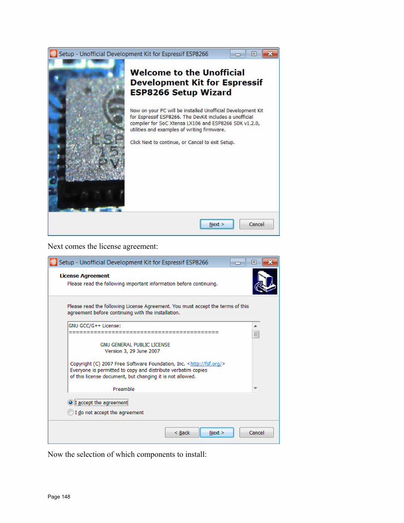
Next comes the license agreement:
Now the selection of which components to install:
Page 148
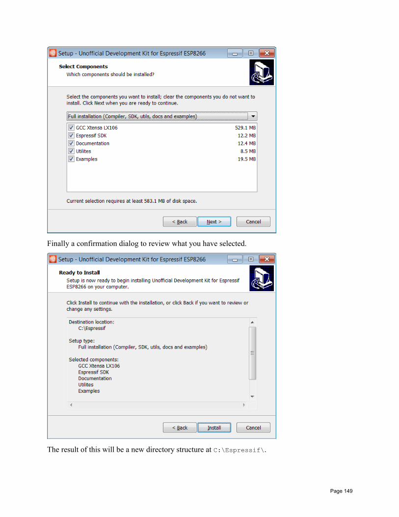
Finally a confirmation dialog to review what you have selected.
The result of this will be a new directory structure at C:\Espressif\.
Page 149
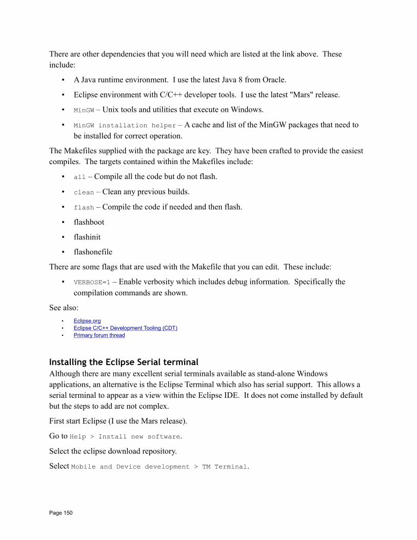
There are other dependencies that you will need which are listed at the link above. These include:
• A Java runtime environment. I use the latest Java 8 from Oracle.
• Eclipse environment with C/C++ developer tools. I use the latest "Mars" release.
• MinGW – Unix tools and utilities that execute on Windows.
• MinGW installation helper – A cache and list of the MinGW packages that need to be installed for correct operation.
The Makefiles supplied with the package are key. They have been crafted to provide the easiest compiles. The targets contained within the Makefiles include:
• all – Compile all the code but do not flash.
• clean – Clean any previous builds.
• flash – Compile the code if needed and then flash.
• flashboot
• flashinit
• flashonefile
There are some flags that are used with the Makefile that you can edit. These include:
• VERBOSE=1 – Enable verbosity which includes debug information. Specifically the compilation commands are shown.
See also:
• Eclipse.org• Eclipse C/C++ Development Tooling (CDT)• Primary forum thread
Installing the Eclipse Serial terminalAlthough there are many excellent serial terminals available as stand-alone Windows applications, an alternative is the Eclipse Terminal which also has serial support. This allows a serial terminal to appear as a view within the Eclipse IDE. It does not come installed by default but the steps to add are not complex.
First start Eclipse (I use the Mars release).
Go to Help > Install new software.
Select the eclipse download repository.
Select Mobile and Device development > TM Terminal.
Page 150
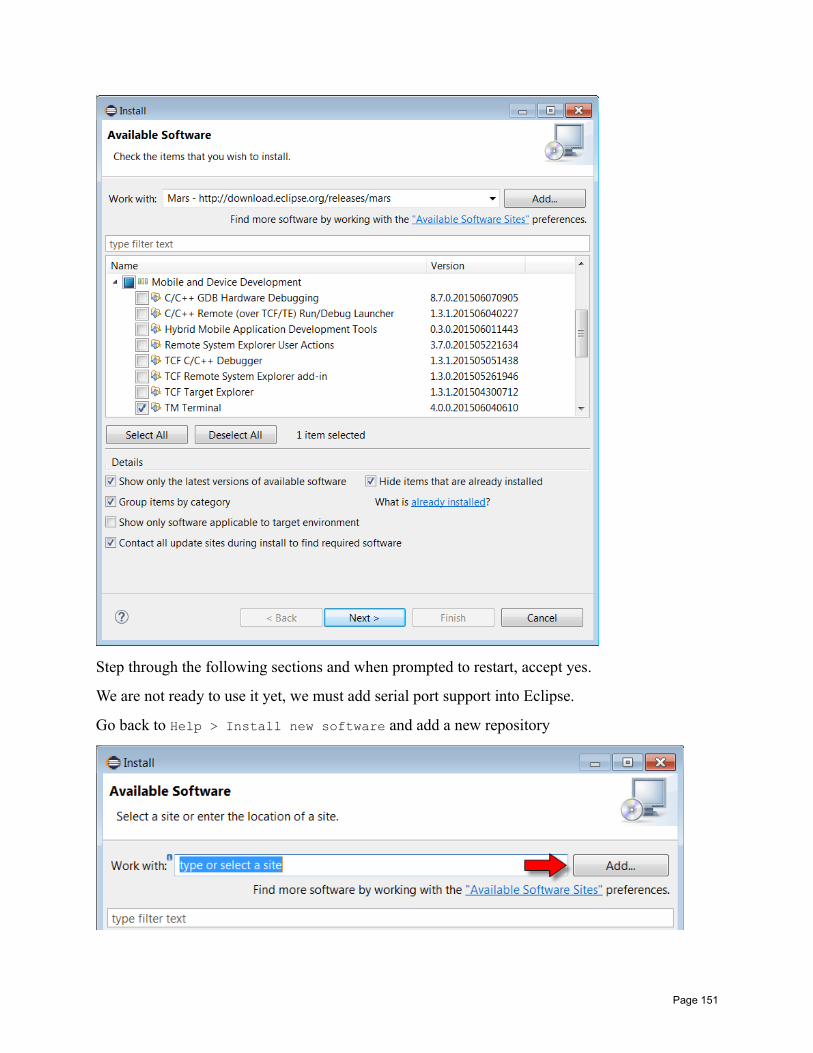
Step through the following sections and when prompted to restart, accept yes.
We are not ready to use it yet, we must add serial port support into Eclipse.
Go back to Help > Install new software and add a new repository
Page 151
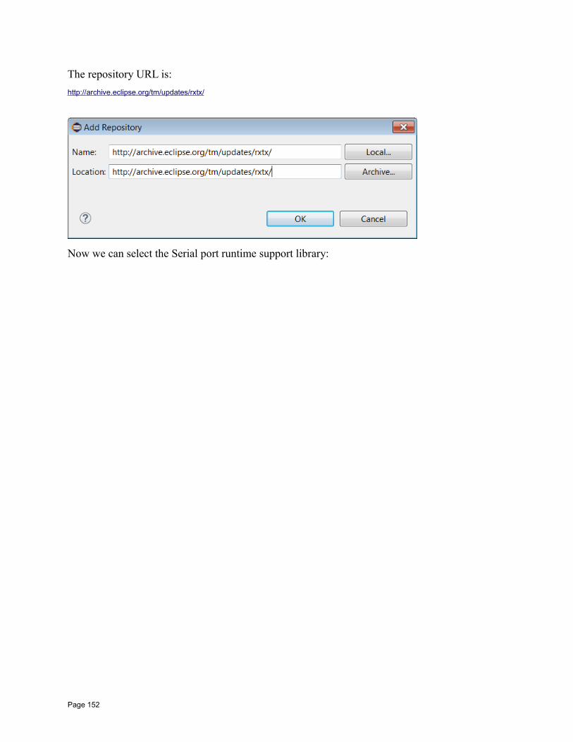
The repository URL is:
http://archive.eclipse.org/tm/updates/rxtx/
Now we can select the Serial port runtime support library:
Page 152
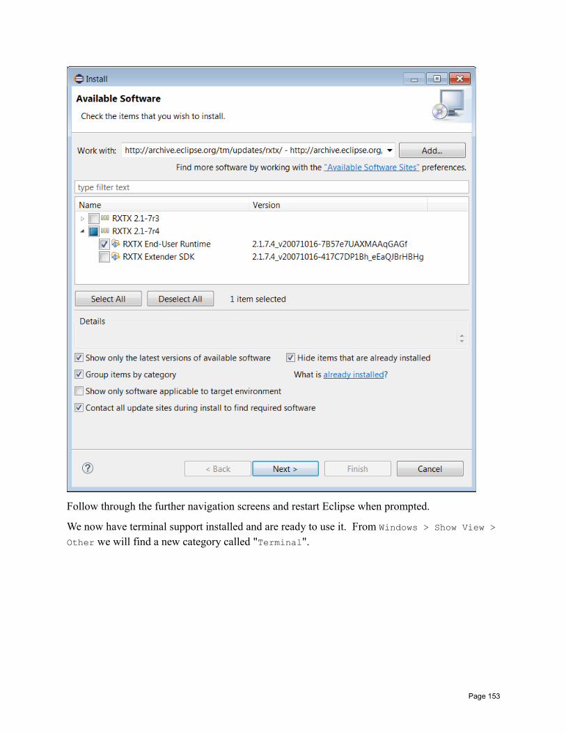
Follow through the further navigation screens and restart Eclipse when prompted.
We now have terminal support installed and are ready to use it. From Windows > Show View >Other we will find a new category called "Terminal".
Page 153
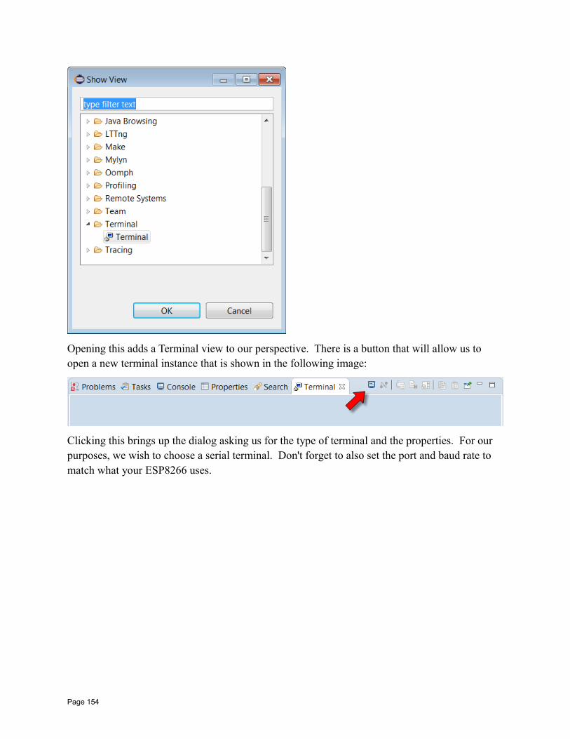
Opening this adds a Terminal view to our perspective. There is a button that will allow us to open a new terminal instance that is shown in the following image:
Clicking this brings up the dialog asking us for the type of terminal and the properties. For our purposes, we wish to choose a serial terminal. Don't forget to also set the port and baud rate to match what your ESP8266 uses.
Page 154
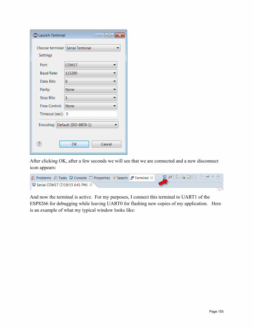
After clicking OK, after a few seconds we will see that we are connected and a new disconnect icon appears:
And now the terminal is active. For my purposes, I connect this terminal to UART1 of the ESP8266 for debugging while leaving UART0 for flashing new copies of my application. Here is an example of what my typical window looks like:
Page 155
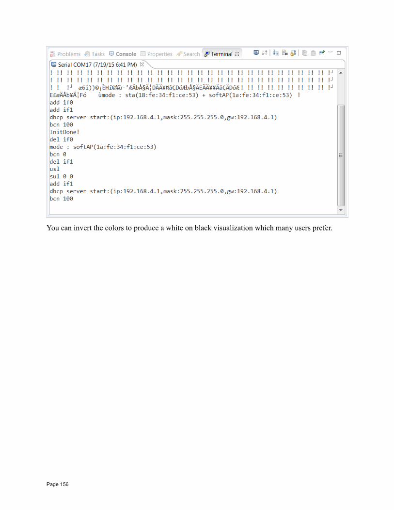
You can invert the colors to produce a white on black visualization which many users prefer.
Page 156
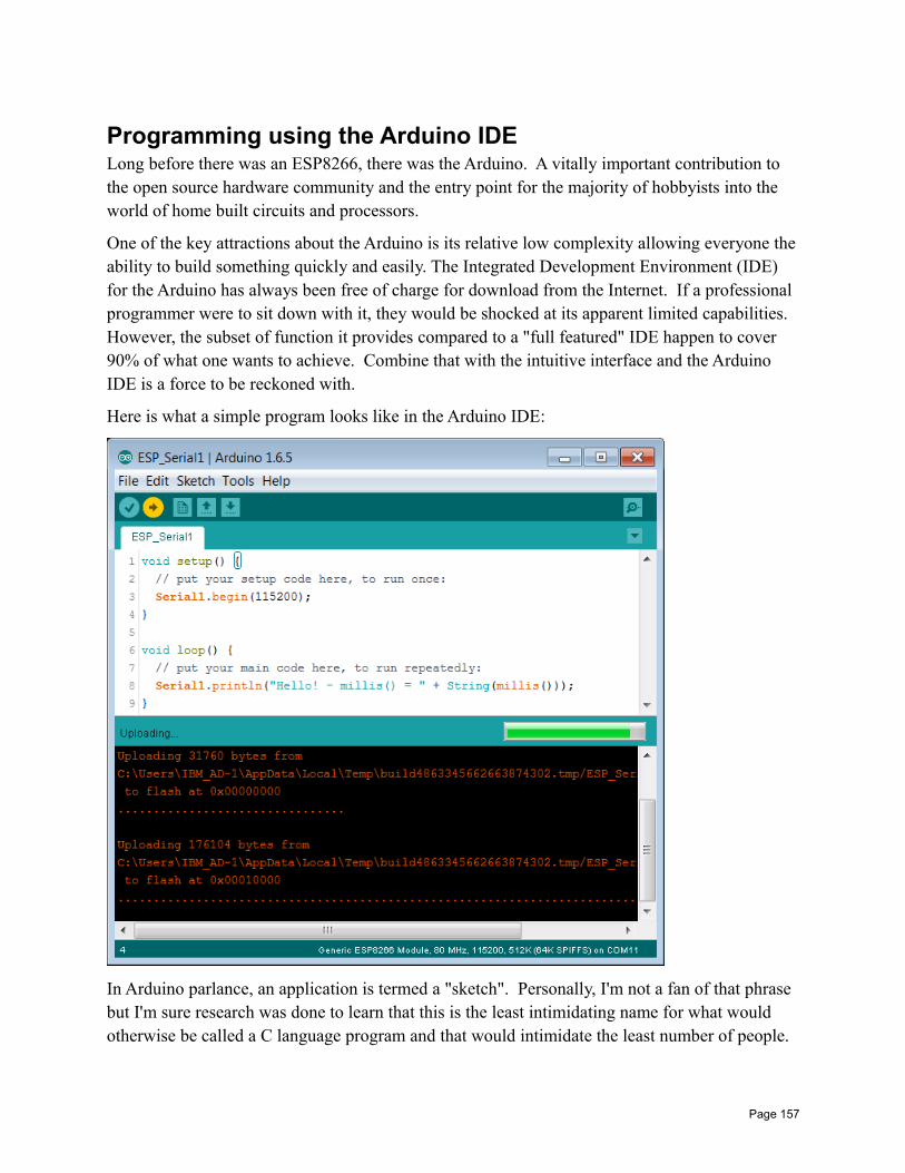
Programming using the Arduino IDELong before there was an ESP8266, there was the Arduino. A vitally important contribution to the open source hardware community and the entry point for the majority of hobbyists into the world of home built circuits and processors.
One of the key attractions about the Arduino is its relative low complexity allowing everyone theability to build something quickly and easily. The Integrated Development Environment (IDE) for the Arduino has always been free of charge for download from the Internet. If a professional programmer were to sit down with it, they would be shocked at its apparent limited capabilities. However, the subset of function it provides compared to a "full featured" IDE happen to cover 90% of what one wants to achieve. Combine that with the intuitive interface and the Arduino IDE is a force to be reckoned with.
Here is what a simple program looks like in the Arduino IDE:
In Arduino parlance, an application is termed a "sketch". Personally, I'm not a fan of that phrase but I'm sure research was done to learn that this is the least intimidating name for what would otherwise be called a C language program and that would intimidate the least number of people.
Page 157
The IDE has a button called "Verify" which, when clicked, compiles the program. Of course, this will also have the side-effect that it will verify that the program compiles cleanly … but compilation is what it does. A second button is called "Upload" that, when clicked, what it does is deploy the application to the Arduino.
In addition to providing a C language editor plus tools to compile and deploy, the Arduino IDE provides pre-supplied libraries of C routines that "hide" complex implementation details that might otherwise be needed when programming to the Arduino boards. For example, UART programming would undoubtedly have to set registers, handle interrupts and more. Instead of making the poor users have to learn these technical APIs. the Arduino folks provided high level libraries that could be called from the sketches with cleaner interfaces which hide the mechanical"gorp" that happens under the covers. This notion is key … as these libraries, as much as anything else, provide the environment for Arduino programmers.
Interesting as this story may be, you may be asking how this relates to our ESP8266 story? Well,a bunch of talented individuals have built out an Open Source project on Github that provides a "plug-in" or "extension" to the Arduino IDE tool (remember, that the Arduino IDE is itself free). What this extension does is allow one to write sketches in the Arduino IDE that leverage the Arduino library interfaces which, at compile and deployment time, generate code that will run onthe ESP8266. What this effectively means is that we can use the Arduino IDE and build ESP8266 applications with the minimum of fuss.
Implications of Arduino IDE supportThe ESP8266 is still new (as of July 2015) and no-one knows where this little chip will be in a year or five years time. Will it become the heart and soul of a new range of hobbyist boards and professional appliances? Will there be something newer and better just around the next corner? We simply don't know.
The ability to treat it as though it were "like" an Arduino is a notion that I haven't been able to fully absorb yet. ESP8266 is a Tensilica CPU unlike the Arduino which is an ATmega CPU. Espressif have created dedicated and architected API in the form of their SDK for directly exposed ESP8266 APIs. The Arduino libraries for ESP8266 seem to map their intent to these exposed APIs. For these reasons and similar, one might argue that the Arduino support is an unnecessary facade on top of a perfectly good environment and by imposing an "alien" technology model on top of the ESP8266 native functions, we are masking access to lower levelsof knowledge and function. Further, thinking of the ESP8266 as though it were an Arduino can lead to design problems. For example, the ESP8266 needs regular control in order to handle WiFi and other internal actions. This conflicts with the Arduino model where the programmer can do what he wants within the loop function for as long as he wants.
The flip side is that the learning curve to get something running on an Arduino has been shown to be extremely low. It doesn't take long at all to get a blinky light going on a breadboard. With
Page 158

that train of thought, why should users of the ESP8266 be penalized for having to install and learn more complex tool chains and syntax to achieve the same result with more ESP8266 oriented tools and techniques? The name of the game should be to allow folks to tinker with CPUs and sensors without having to have university degrees in computing science or electrical engineering and if the price one pays to get there is to insert a "simple to use" illusion then why not? If I build a paper airplane and throw it out my window … I may get pleasure from that. A NASA rocket scientist shouldn't scoff at my activities or lack of knowledge of aerodynamics … the folded paper did its job and I achieved my goal. However, if my job was to put a man on the moon, the ability to visualize the realities of the technology at the "realistic" level becomes extremely important.
Installing the Arduino IDE with ESP8266 supportTo assemble this environment, one must download a current version of the Arduino IDE. This will be about 140 Mbytes.
I download the ZIP file version and then extract its content.
Next, we launch the Arduino IDE and open the Preferences dialog:
Page 159
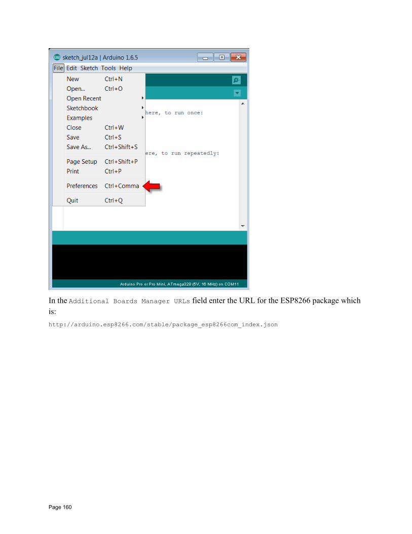
In the Additional Boards Manager URLs field enter the URL for the ESP8266 package which is:
http://arduino.esp8266.com/stable/package_esp8266com_index.json
Page 160
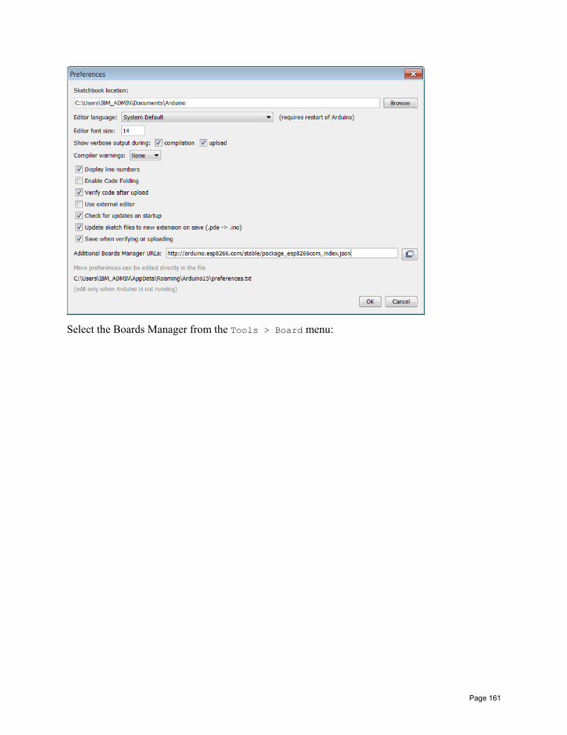
Select the Boards Manager from the Tools > Board menu:
Page 161
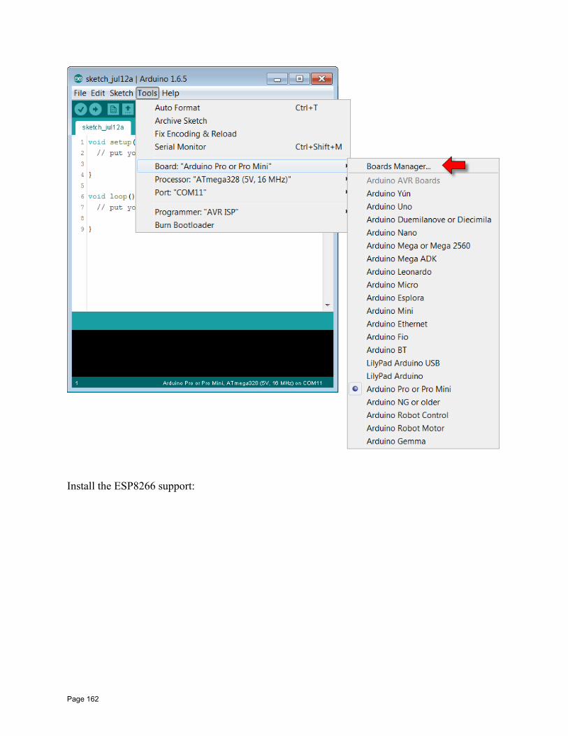
Install the ESP8266 support:
Page 162
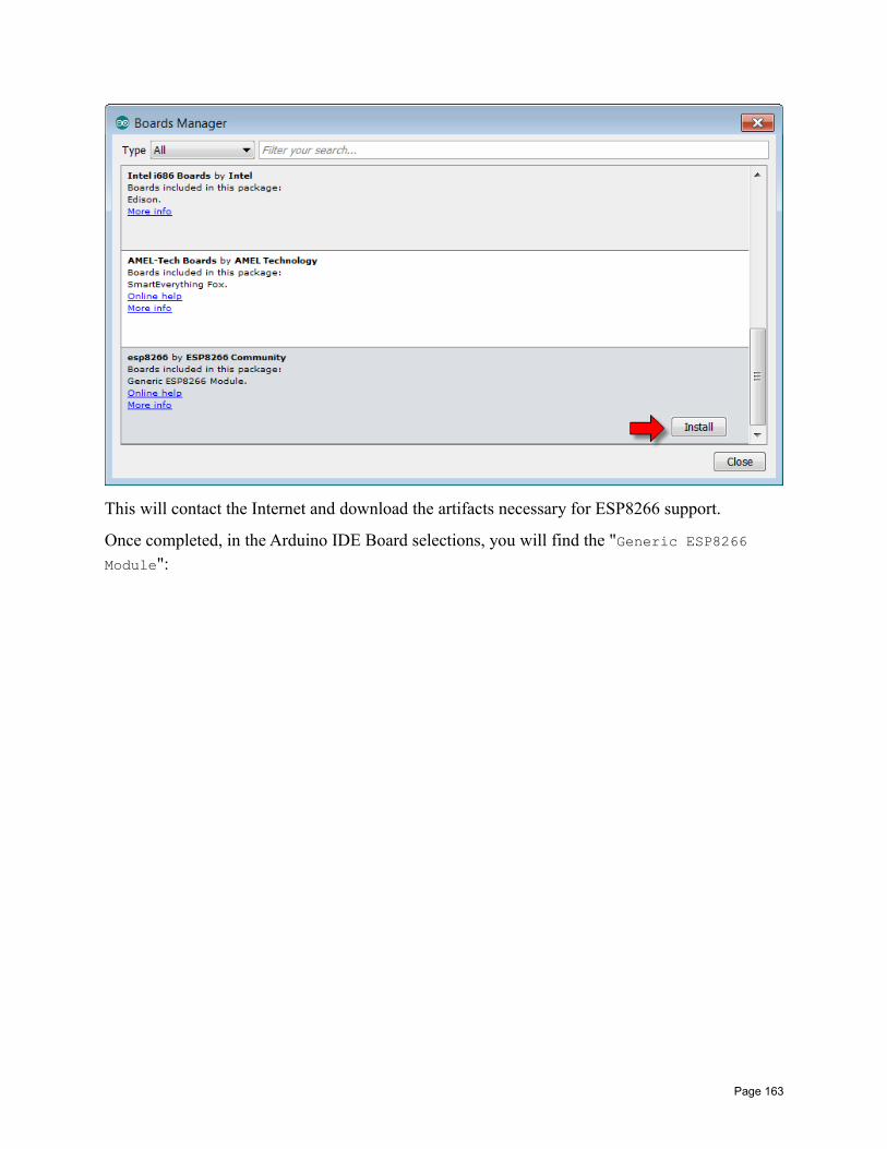
This will contact the Internet and download the artifacts necessary for ESP8266 support.
Once completed, in the Arduino IDE Board selections, you will find the "Generic ESP8266 Module":
Page 163
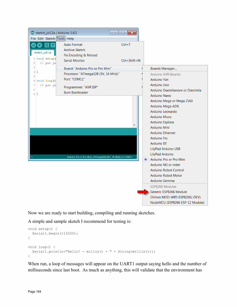
Now we are ready to start building, compiling and running sketches.
A simple and sample sketch I recommend for testing is:
void setup() Serial1.begin(115200);
void loop() Serial1.println("Hello! - millis() = " + String(millis()));
When run, a loop of messages will appear on the UART1 output saying hello and the number of milliseconds since last boot. As much as anything, this will validate that the environment has
Page 164
been setup correctly, you can compile a program and that deployment to the ESP8266 is successful.
See also:
• Github: esp8266/Arduino• Arduino IDE
Tips for working in the Arduino environmentRemember that the Arduino environment is two things. First, an actual application that you install on your machine providing the Arduino IDE. Second, a set of libraries that model those available to an actual Arduino device which are mapped to ESP8266 capabilities. With that in mind, here are some hints and tips that I find useful when writing Arduino sketches for an ESP8266 environment.
Initialize global classes in setup()Within an Arduino sketch, we have a pre-supplied function called setup() that is called only once during ESP8266 boot-up. Within this function, you perform one time initialization functions. In C++, we have the ability to create class instances globally. For example:
MyClass myClass(123);
void setup() // Some code here
instead of this, use the following:
MyClass *myClass;
void setup() myClass = new MyClass(123);// Some code here
This of course changes your variable's data type. It went from being an instance of MyClass to being a pointer to an instance of MyClass which means that you might have to change other aspects of your program … but the reason for this is that in the first case, the constructor for yourMyClass instance ran outside of the setup() and we can't say what state the environment might have been in at that point. Within the setup() code, we have a reasonable expectation of the environment context.
Invoking Espressif SDK API from a sketchThere is nothing to prevent you from invoking Espressif SDK API from within your sketch. Youmust include any include files that are necessary. Here is an example of including "user_interface.h".
Page 165
extern "C" #include "user_interface.h"
Notice the bracketing with the C++ construct that causes the content to appear as though it were being defined in a C program.
Exception handlingWhen an exception is detected in the code, the code halts. Typically we see the following loggedto the serial port when this happens:
ets Jan 8 2013,rst cause:2, boot mode:(1,7)
ets Jan 8 2013,rst cause:4, boot mode:(1,7)
wdt reset
Unfortunately, this tells us absolutely nothing about the location or cause of the issue.
The SPIFFS file system
The mkspiffs commandA tool has been made available that builds a "spiffs" file system binary from a directory structure found on disk. The command is called "mkspiffs" and has its own github project.
The full syntax of the command is:
mkspiffs -c <pack_dir>|-l|-i [-b <number>] [-p <number>] [-s <number>] [–][-version] [-h] <image_file>
Where the parameters are:
• -c <pack_dir> or --create <pack_dir> – Create a spiffs image file from examinationof a directory to be packed into the spiffs image.
• -l or --list – List the content of an existing image file.
• -i or --visualize – Visualize the spiffs image.
• -b <number> or --block <number> – The File System size blocks size in bytes.
• -p <number> or --page <number> – The File System page size in bytes.
• -s <number> or --size <number> – The File System image size in bytes.
• -- or --ignore_rest – Ignore the remaining arguments.
• --version – Display the version information.
• -h or --help – Display usage/help information
Page 166
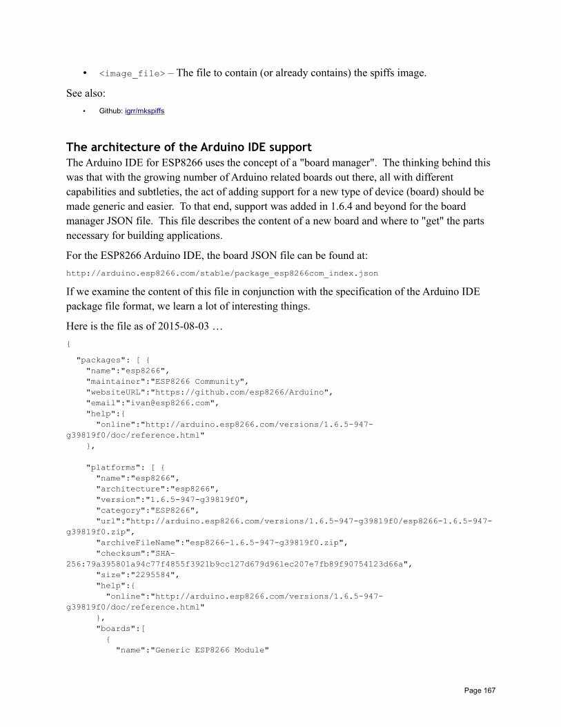
• <image_file> – The file to contain (or already contains) the spiffs image.
See also:
• Github: igrr/mkspiffs
The architecture of the Arduino IDE supportThe Arduino IDE for ESP8266 uses the concept of a "board manager". The thinking behind this was that with the growing number of Arduino related boards out there, all with different capabilities and subtleties, the act of adding support for a new type of device (board) should be made generic and easier. To that end, support was added in 1.6.4 and beyond for the board manager JSON file. This file describes the content of a new board and where to "get" the parts necessary for building applications.
For the ESP8266 Arduino IDE, the board JSON file can be found at:
http://arduino.esp8266.com/stable/package_esp8266com_index.json
If we examine the content of this file in conjunction with the specification of the Arduino IDE package file format, we learn a lot of interesting things.
Here is the file as of 2015-08-03 …
"packages": [ "name":"esp8266", "maintainer":"ESP8266 Community", "websiteURL":"https://github.com/esp8266/Arduino", "email":"[email protected]", "help": "online":"http://arduino.esp8266.com/versions/1.6.5-947-g39819f0/doc/reference.html" ,
"platforms": [ "name":"esp8266", "architecture":"esp8266", "version":"1.6.5-947-g39819f0", "category":"ESP8266", "url":"http://arduino.esp8266.com/versions/1.6.5-947-g39819f0/esp8266-1.6.5-947-g39819f0.zip", "archiveFileName":"esp8266-1.6.5-947-g39819f0.zip", "checksum":"SHA-256:79a395801a94c77f4855f3921b9cc127d679d961ec207e7fb89f90754123d66a", "size":"2295584", "help": "online":"http://arduino.esp8266.com/versions/1.6.5-947-g39819f0/doc/reference.html" , "boards":[ "name":"Generic ESP8266 Module"
Page 167
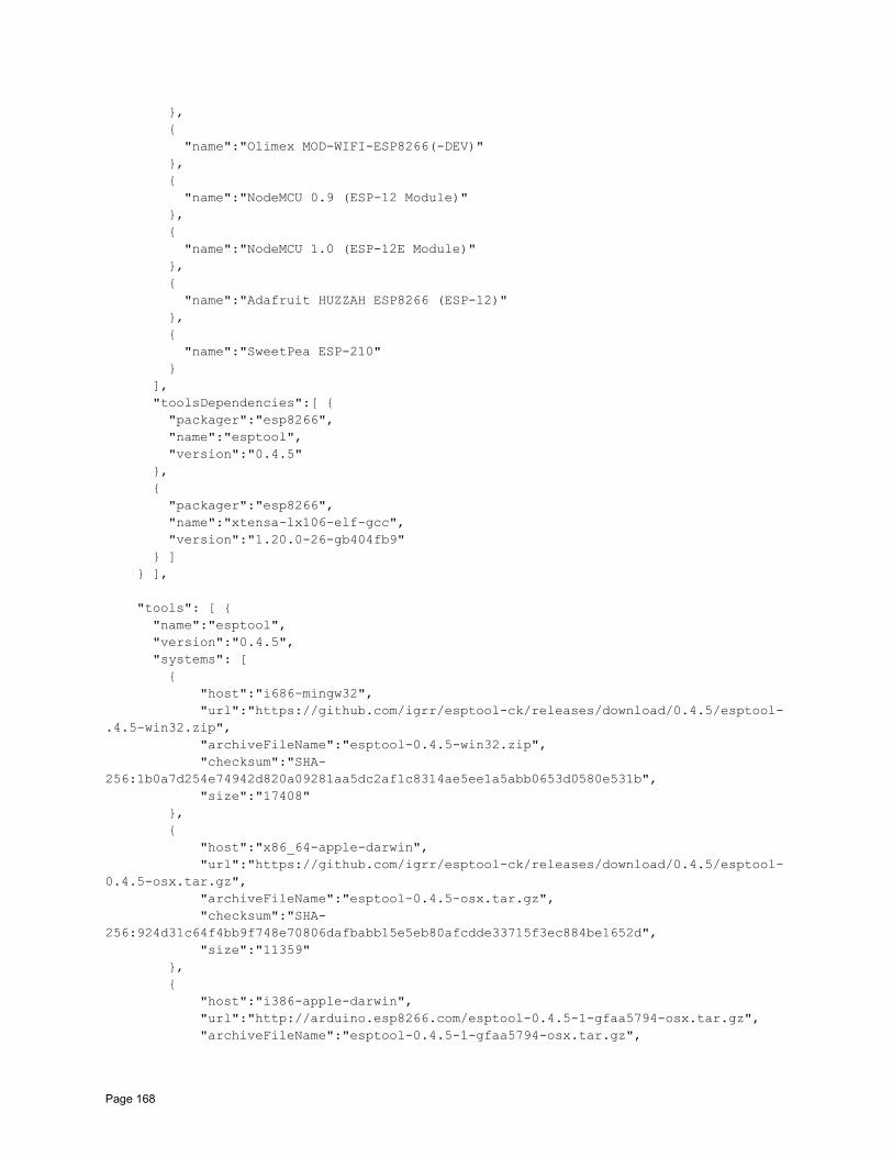
, "name":"Olimex MOD-WIFI-ESP8266(-DEV)" , "name":"NodeMCU 0.9 (ESP-12 Module)" , "name":"NodeMCU 1.0 (ESP-12E Module)" , "name":"Adafruit HUZZAH ESP8266 (ESP-12)" , "name":"SweetPea ESP-210" ], "toolsDependencies":[ "packager":"esp8266", "name":"esptool", "version":"0.4.5" , "packager":"esp8266", "name":"xtensa-lx106-elf-gcc", "version":"1.20.0-26-gb404fb9" ] ],
"tools": [ "name":"esptool", "version":"0.4.5", "systems": [ "host":"i686-mingw32", "url":"https://github.com/igrr/esptool-ck/releases/download/0.4.5/esptool-.4.5-win32.zip", "archiveFileName":"esptool-0.4.5-win32.zip", "checksum":"SHA-256:1b0a7d254e74942d820a09281aa5dc2af1c8314ae5ee1a5abb0653d0580e531b", "size":"17408" , "host":"x86_64-apple-darwin", "url":"https://github.com/igrr/esptool-ck/releases/download/0.4.5/esptool-0.4.5-osx.tar.gz", "archiveFileName":"esptool-0.4.5-osx.tar.gz", "checksum":"SHA-256:924d31c64f4bb9f748e70806dafbabb15e5eb80afcdde33715f3ec884be1652d", "size":"11359" , "host":"i386-apple-darwin", "url":"http://arduino.esp8266.com/esptool-0.4.5-1-gfaa5794-osx.tar.gz", "archiveFileName":"esptool-0.4.5-1-gfaa5794-osx.tar.gz",
Page 168
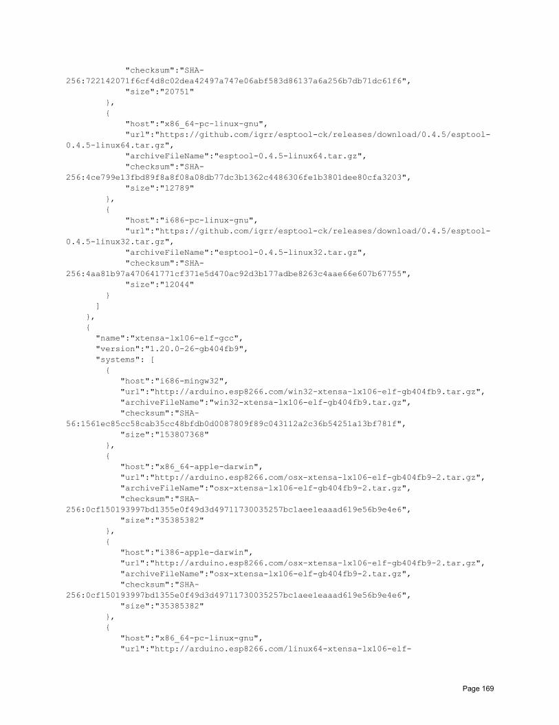
"checksum":"SHA-256:722142071f6cf4d8c02dea42497a747e06abf583d86137a6a256b7db71dc61f6", "size":"20751" , "host":"x86_64-pc-linux-gnu", "url":"https://github.com/igrr/esptool-ck/releases/download/0.4.5/esptool-0.4.5-linux64.tar.gz", "archiveFileName":"esptool-0.4.5-linux64.tar.gz", "checksum":"SHA-256:4ce799e13fbd89f8a8f08a08db77dc3b1362c4486306fe1b3801dee80cfa3203", "size":"12789" , "host":"i686-pc-linux-gnu", "url":"https://github.com/igrr/esptool-ck/releases/download/0.4.5/esptool-0.4.5-linux32.tar.gz", "archiveFileName":"esptool-0.4.5-linux32.tar.gz", "checksum":"SHA-256:4aa81b97a470641771cf371e5d470ac92d3b177adbe8263c4aae66e607b67755", "size":"12044" ] , "name":"xtensa-lx106-elf-gcc", "version":"1.20.0-26-gb404fb9", "systems": [ "host":"i686-mingw32", "url":"http://arduino.esp8266.com/win32-xtensa-lx106-elf-gb404fb9.tar.gz", "archiveFileName":"win32-xtensa-lx106-elf-gb404fb9.tar.gz", "checksum":"SHA-56:1561ec85cc58cab35cc48bfdb0d0087809f89c043112a2c36b54251a13bf781f", "size":"153807368" , "host":"x86_64-apple-darwin", "url":"http://arduino.esp8266.com/osx-xtensa-lx106-elf-gb404fb9-2.tar.gz", "archiveFileName":"osx-xtensa-lx106-elf-gb404fb9-2.tar.gz", "checksum":"SHA-256:0cf150193997bd1355e0f49d3d49711730035257bc1aee1eaaad619e56b9e4e6", "size":"35385382" , "host":"i386-apple-darwin", "url":"http://arduino.esp8266.com/osx-xtensa-lx106-elf-gb404fb9-2.tar.gz", "archiveFileName":"osx-xtensa-lx106-elf-gb404fb9-2.tar.gz", "checksum":"SHA-256:0cf150193997bd1355e0f49d3d49711730035257bc1aee1eaaad619e56b9e4e6", "size":"35385382" , "host":"x86_64-pc-linux-gnu", "url":"http://arduino.esp8266.com/linux64-xtensa-lx106-elf-
Page 169
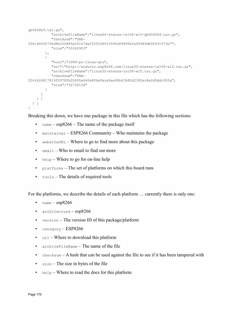
gb404fb9.tar.gz", "archiveFileName":"linux64-xtensa-lx106-elf-gb404fb9.tar.gz", "checksum":"SHA-256:46f057fbd8b320889a26167daf325038912096d09940b2a95489db92431473b7", "size":"30262903" , "host":"i686-pc-linux-gnu", "url":"http://arduino.esp8266.com/linux32-xtensa-lx106-elf.tar.gz", "archiveFileName":"linux32-xtensa-lx106-elf.tar.gz", "checksum":"SHA-256:b24817819f0078fb05895a640e806e0aca9aa96b47b80d2390ac8e2d9ddc955a", "size":"32734156" ] ] ]
Breaking this down, we have one package in this file which has the following sections:
• name – esp8266 – The name of the package itself
• maintainer – ESP8266 Community – Who maintains the package
• websiteURL – Where to go to find more about this package
• email – Who to email to find out more
• help – Where to go for on-line help
• platforms – The set of platforms on which this board runs
• tools – The details of required tools
For the platforms, we describe the details of each platform … currently there is only one:
• name – esp8266
• architecture – esp8266
• version – The version ID of this package/platform
• category – ESP8266
• url – Where to download this platform
• archiveFileName – The name of the file
• checksum – A hash that can be used against the file to see if it has been tampered with
• size – The size in bytes of the file
• help – Where to read the docs for this platform
Page 170
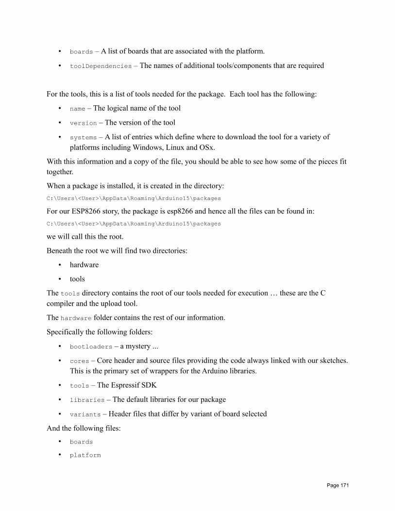
• boards – A list of boards that are associated with the platform.
• toolDependencies – The names of additional tools/components that are required
For the tools, this is a list of tools needed for the package. Each tool has the following:
• name – The logical name of the tool
• version – The version of the tool
• systems – A list of entries which define where to download the tool for a variety of platforms including Windows, Linux and OSx.
With this information and a copy of the file, you should be able to see how some of the pieces fit together.
When a package is installed, it is created in the directory:
C:\Users\<User>\AppData\Roaming\Arduino15\packages
For our ESP8266 story, the package is esp8266 and hence all the files can be found in:
C:\Users\<User>\AppData\Roaming\Arduino15\packages
we will call this the root.
Beneath the root we will find two directories:
• hardware
• tools
The tools directory contains the root of our tools needed for execution … these are the C compiler and the upload tool.
The hardware folder contains the rest of our information.
Specifically the following folders:
• bootloaders – a mystery ...
• cores – Core header and source files providing the code always linked with our sketches.This is the primary set of wrappers for the Arduino libraries.
• tools – The Espressif SDK
• libraries – The default libraries for our package
• variants – Header files that differ by variant of board selected
And the following files:
• boards
• platform
Page 171
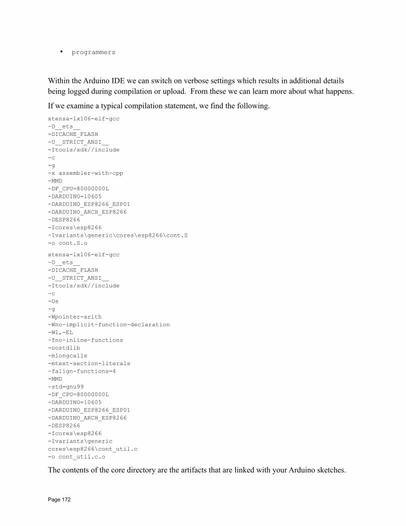
• programmers
Within the Arduino IDE we can switch on verbose settings which results in additional details being logged during compilation or upload. From these we can learn more about what happens.
If we examine a typical compilation statement, we find the following.
xtensa-lx106-elf-gcc-D__ets__-DICACHE_FLASH-U__STRICT_ANSI__-Itools/sdk//include-c-g-x assembler-with-cpp-MMD-DF_CPU=80000000L-DARDUINO=10605-DARDUINO_ESP8266_ESP01-DARDUINO_ARCH_ESP8266-DESP8266-Icores\esp8266-Ivariants\generic\cores\esp8266\cont.S-o cont.S.o
xtensa-lx106-elf-gcc-D__ets__-DICACHE_FLASH-U__STRICT_ANSI__-Itools/sdk//include-c-Os-g-Wpointer-arith-Wno-implicit-function-declaration-Wl,-EL-fno-inline-functions-nostdlib-mlongcalls-mtext-section-literals-falign-functions=4-MMD-std=gnu99-DF_CPU=80000000L-DARDUINO=10605-DARDUINO_ESP8266_ESP01-DARDUINO_ARCH_ESP8266-DESP8266-Icores\esp8266-Ivariants\generic cores\esp8266\cont_util.c-o cont_util.c.o
The contents of the core directory are the artifacts that are linked with your Arduino sketches.
Page 172

spiffs
abi.cpp
Arduino.h Primary include file for applications.
binary.h Binary definitions for the range 0-255 up to 8 bits.
cbuf.h Circular buffer.
Client.h
cont.h
cont.S
cont_util.c
core_esp8266_eboot_command.c
core_esp8266_flash_utils.c
core_esp8266_i2s.c
core_esp8266_main.cpp The main entry point into the ESP application.
core_esp8266_noniso.c
core_esp8266_phy.c
core_esp8266_postmortem.c
core_esp8266_si2c.c
core_esp8266_sigma_delta.c.unused
core_esp8266_timer.c
core_esp8266_wiring.c
core_esp8266_wiring_analog.c
core_esp8266_wiring_digital.c
core_esp8266_wiring_pulse.c
core_esp8266_wiring_pwm.c
core_esp8266_wiring_shift.c
debug.cpp
debug.h
eboot_command.h
Esp.cpp
Esp.h
esp8266_peri.h
flash_utils.h
HardwareSerial.cpp
HardwareSerial.h
i2s.h
IPAddress.cpp
IPAddress.h
Page 173

libc_replacements.c
pgmspace.cpp
pgmspace.h
Print.cpp
Print.h
Printable.h
Server.h
sigma_delta.h
stdlib_noniso.h
Stream.cpp
Stream.h
Tone.cpp
twi.h
Udp.h
Updater.cpp
Updater.h
user_config.h
Wcharacter.h
wiring_private.h
Wmath.cpp
Wstring.cpp
Wstring.h
When we look at how an application is uploaded, we see a command similar to the following:
esptool.exe -vv -cd ck -cb 115200 -cp COM11 -ca 0x00000 -cf ESP_I2CScanner.cpp.bin
Building ESP Arduino apps using the Eclipse IDENow our heads are really going to hurt … there is no easy way to get through this … but the story is important and the results are great.
So far we have seen that we can build ESP programs using a C compiler and the Espressif SDK. We have also seen that we can build these programs within an Eclipse environment … also against the Espressif SDK. We have just examined the notion of building programs using the Arduino IDE which provides mappings to many of the Arduino libraries implemented for ESP. Now we are going to return to using Eclipse but this time as an alternative to the Arduino IDE but still using the Arduino libraries to build "Arduino flavored" ESP programs.
Page 174
The key to this story is the excellent Open Source Eclipse tooling for Arduino building found here:
http://eclipse.baeyens.it/index.html
This set of plug-ins to the Eclipse framework leverages an existing Arduino environment such as the one that we have just built which includes the ESP support. The plug-ins interrogate the Arduino IDE setup and provide the build and editing tools used there.
Before going any further, it is vital that you get the ESP Arduino IDE working by following all the instructions necessary to build solutions using that environment. That is a prerequisite for getting the Eclipse environment working.
We have two choices for getting the Eclipse environment working. The first is to download a fully prepared Eclipse environment that includes the C development tools and the plug-ins for Arduino support. This is the easiest … however it is also likely that you have an existing Eclipseframework already installed that you may wish to re-use or extend. Eclipse is meant to be an extensible environment which provides a framework into which additional plug-ins can be addedas needed. In that pattern, we can download the latest Eclipse framework (Mars) and then add inthe relevant plug-ins.
Here is an example of getting ready using a pre-built Eclipse download.
First download a current overnight build … and extract its content. Note that the maintainer is distributing files in tar.gz format. I use 7-Zip to decompress. The download size is about 170MBytes so make sure you download sooner than later. Make sure that you download the correct version of the Eclipse environment that corresponds to the version of Java you have installed. For example, if you have 32bit Java installed, don't download the 64bit version of Eclipse. If you do and attempt to launch Eclipse, you will get errors that you will have to dig into only to find buried in logs that there is an incompatibility. If you do make the error, the message you receive might look like:
Page 175
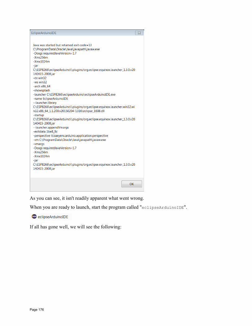
As you can see, it isn't readily apparent what went wrong.
When you are ready to launch, start the program called "eclipseArduinoIDE".
If all has gone well, we will see the following:
Page 176
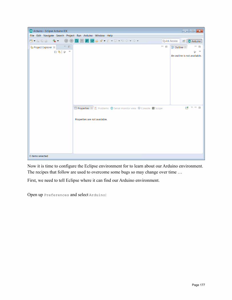
Now it is time to configure the Eclipse environment for to learn about our Arduino environment. The recipes that follow are used to overcome some bugs so may change over time …
First, we need to tell Eclipse where it can find our Arduino environment.
Open up Preferences and select Arduino:
Page 177
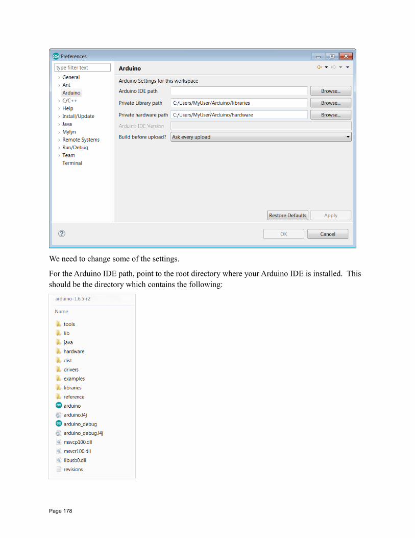
We need to change some of the settings.
For the Arduino IDE path, point to the root directory where your Arduino IDE is installed. This should be the directory which contains the following:
Page 178
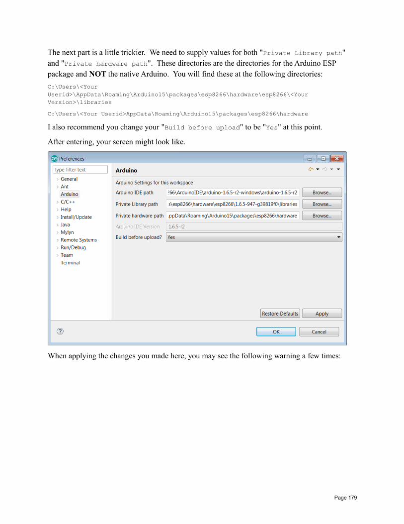
The next part is a little trickier. We need to supply values for both "Private Library path" and "Private hardware path". These directories are the directories for the Arduino ESP package and NOT the native Arduino. You will find these at the following directories:
C:\Users\<Your Userid>\AppData\Roaming\Arduino15\packages\esp8266\hardware\esp8266\<Your Version>\libraries
C:\Users\<Your Userid>AppData\Roaming\Arduino15\packages\esp8266\hardware
I also recommend you change your "Build before upload" to be "Yes" at this point.
After entering, your screen might look like.
When applying the changes you made here, you may see the following warning a few times:
Page 179
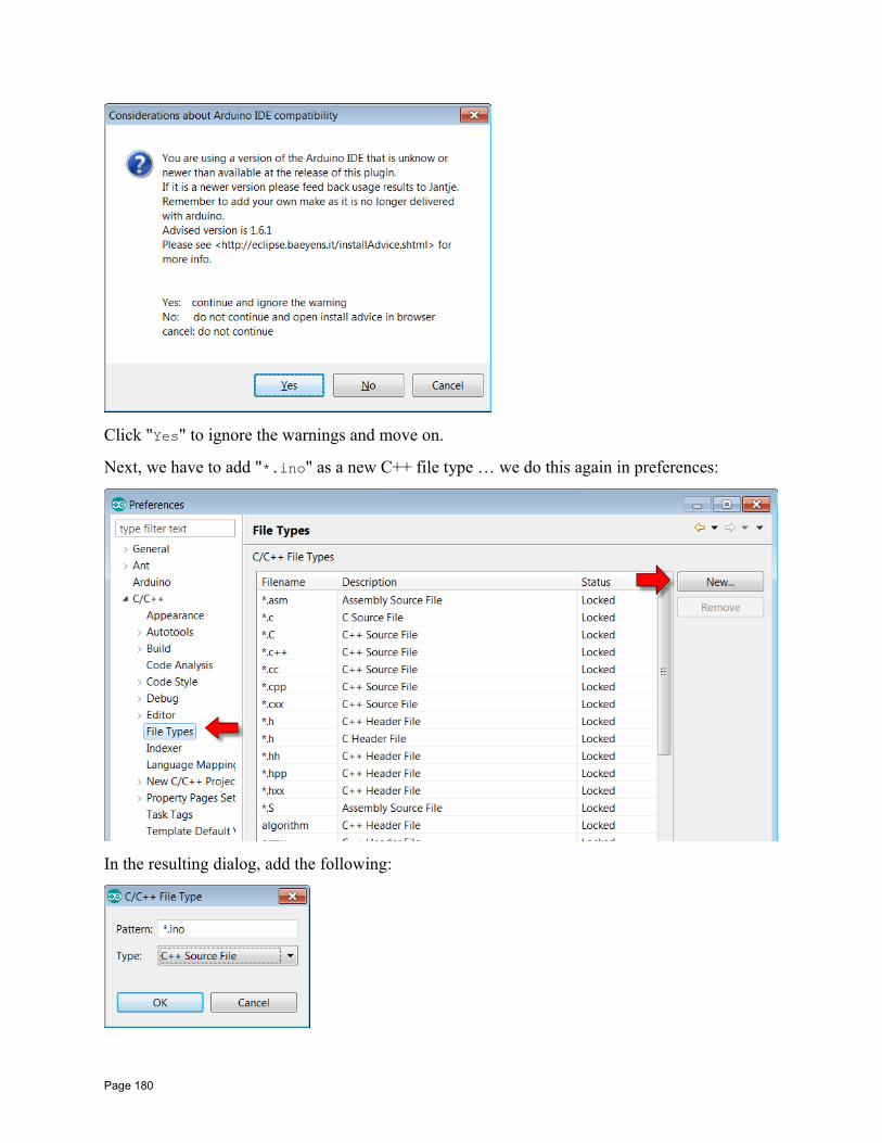
Click "Yes" to ignore the warnings and move on.
Next, we have to add "*.ino" as a new C++ file type … we do this again in preferences:
In the resulting dialog, add the following:
Page 180
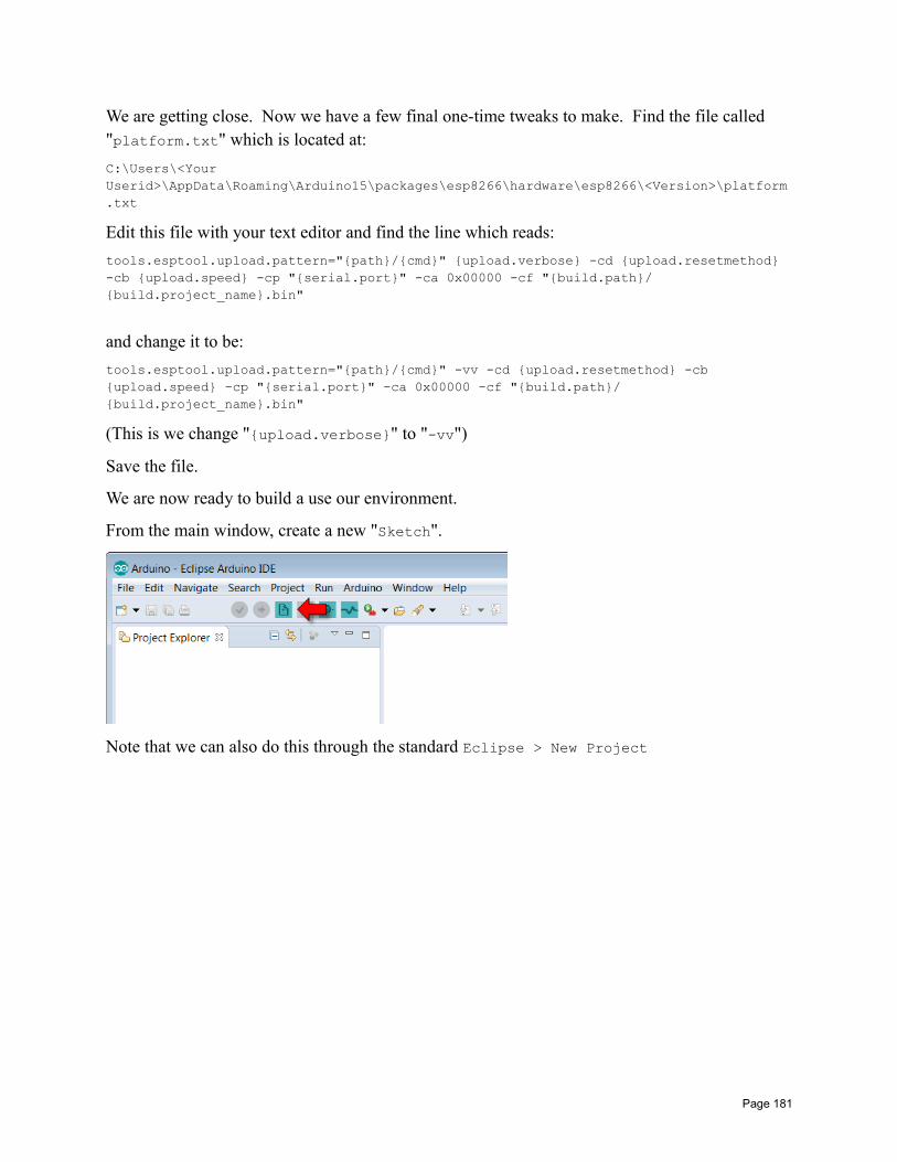
We are getting close. Now we have a few final one-time tweaks to make. Find the file called "platform.txt" which is located at:
C:\Users\<Your Userid>\AppData\Roaming\Arduino15\packages\esp8266\hardware\esp8266\<Version>\platform.txt
Edit this file with your text editor and find the line which reads:
tools.esptool.upload.pattern="path/cmd" upload.verbose -cd upload.resetmethod -cb upload.speed -cp "serial.port" -ca 0x00000 -cf "build.path/build.project_name.bin"
and change it to be:
tools.esptool.upload.pattern="path/cmd" -vv -cd upload.resetmethod -cb upload.speed -cp "serial.port" -ca 0x00000 -cf "build.path/build.project_name.bin"
(This is we change "upload.verbose" to "-vv")
Save the file.
We are now ready to build a use our environment.
From the main window, create a new "Sketch".
Note that we can also do this through the standard Eclipse > New Project
Page 181
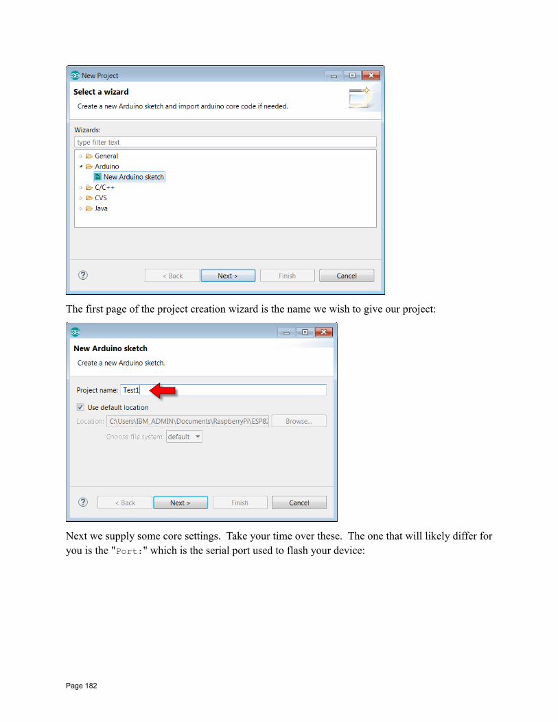
The first page of the project creation wizard is the name we wish to give our project:
Next we supply some core settings. Take your time over these. The one that will likely differ foryou is the "Port:" which is the serial port used to flash your device:
Page 182
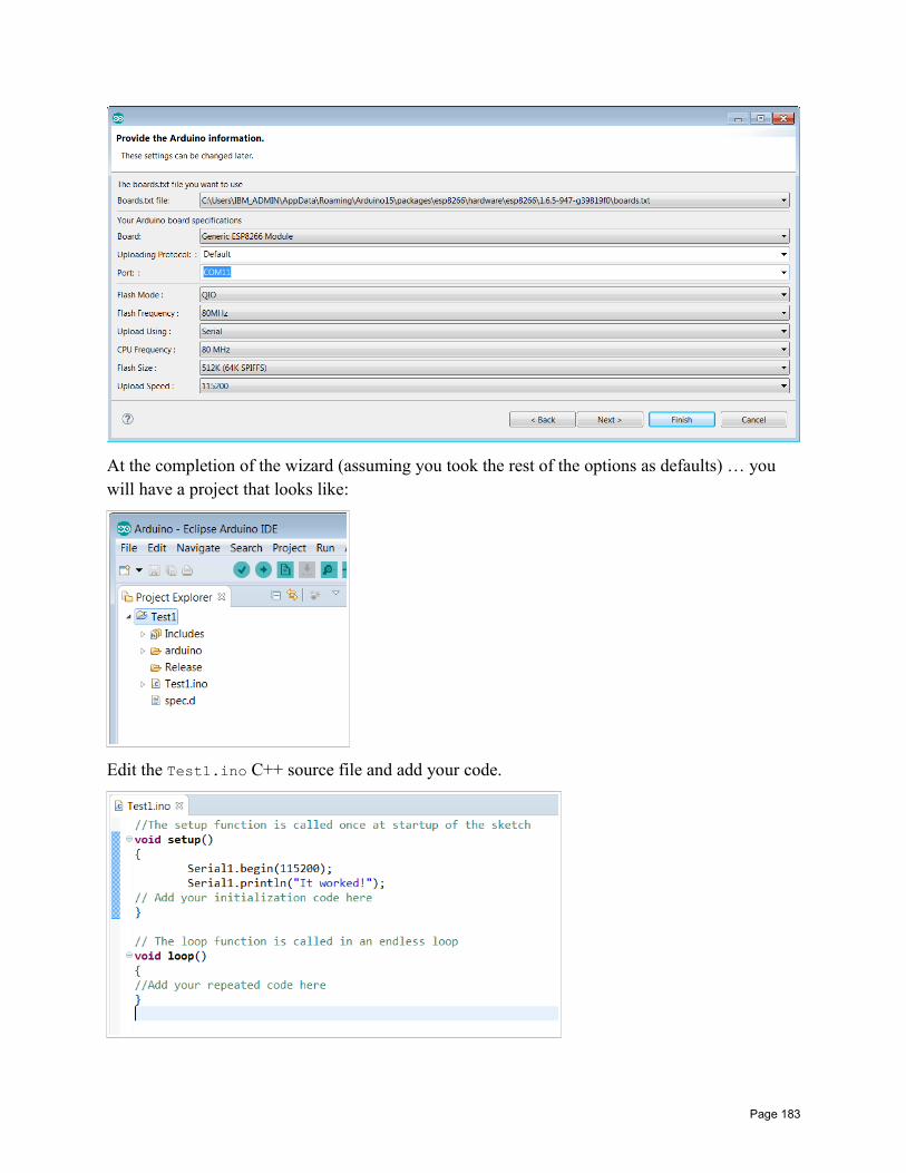
At the completion of the wizard (assuming you took the rest of the options as defaults) … you will have a project that looks like:
Edit the Test1.ino C++ source file and add your code.
Page 183
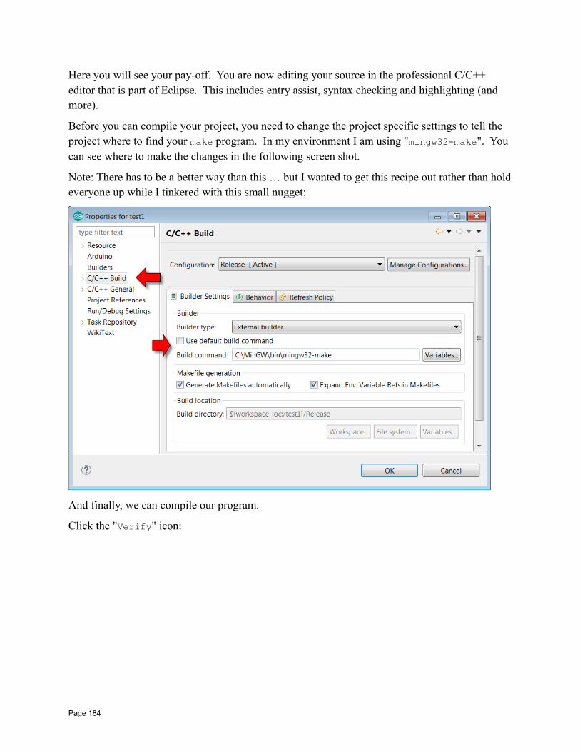
Here you will see your pay-off. You are now editing your source in the professional C/C++ editor that is part of Eclipse. This includes entry assist, syntax checking and highlighting (and more).
Before you can compile your project, you need to change the project specific settings to tell the project where to find your make program. In my environment I am using "mingw32-make". You can see where to make the changes in the following screen shot.
Note: There has to be a better way than this … but I wanted to get this recipe out rather than holdeveryone up while I tinkered with this small nugget:
And finally, we can compile our program.
Click the "Verify" icon:
Page 184
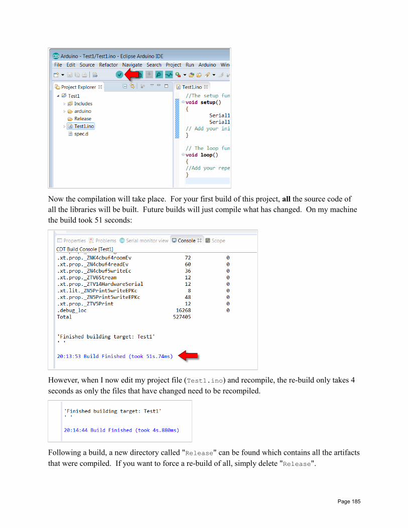
Now the compilation will take place. For your first build of this project, all the source code of all the libraries will be built. Future builds will just compile what has changed. On my machine the build took 51 seconds:
However, when I now edit my project file (Test1.ino) and recompile, the re-build only takes 4 seconds as only the files that have changed need to be recompiled.
Following a build, a new directory called "Release" can be found which contains all the artifactsthat were compiled. If you want to force a re-build of all, simply delete "Release".
Page 185
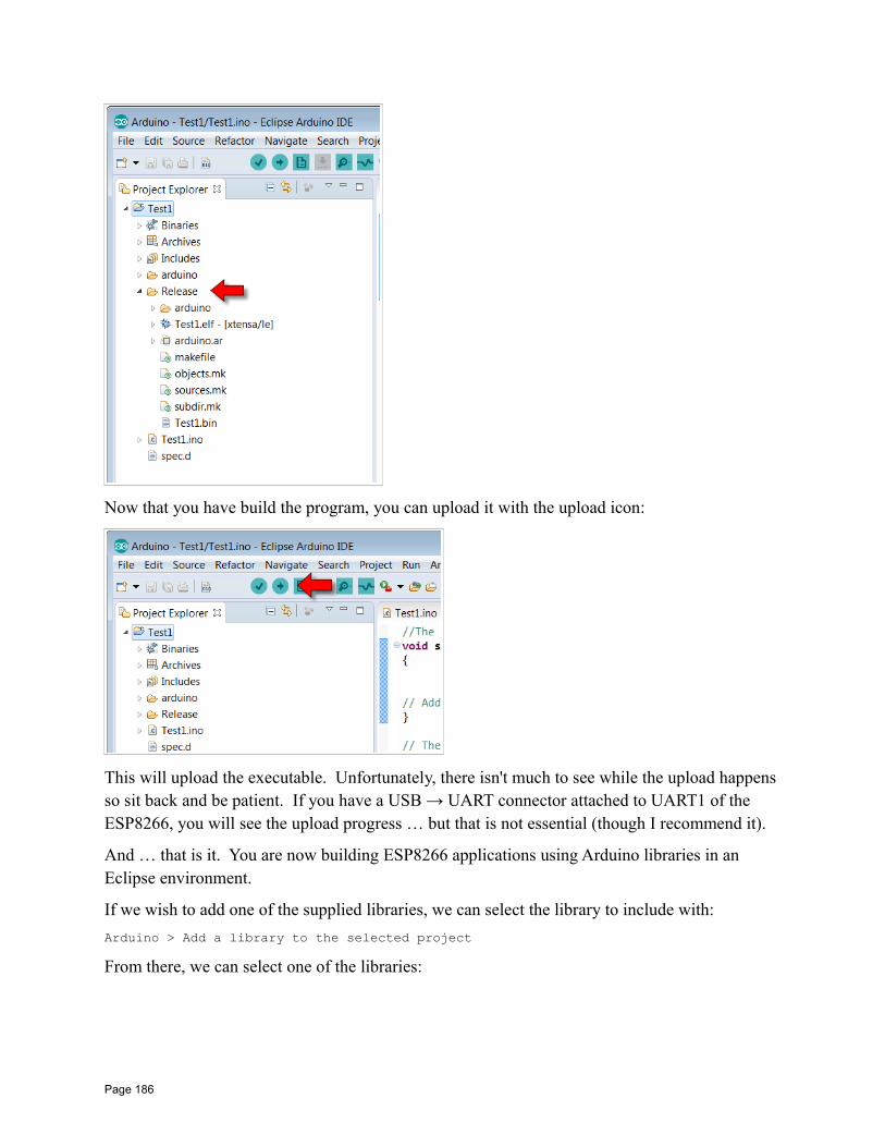
Now that you have build the program, you can upload it with the upload icon:
This will upload the executable. Unfortunately, there isn't much to see while the upload happens so sit back and be patient. If you have a USB → UART connector attached to UART1 of the ESP8266, you will see the upload progress … but that is not essential (though I recommend it).
And … that is it. You are now building ESP8266 applications using Arduino libraries in an Eclipse environment.
If we wish to add one of the supplied libraries, we can select the library to include with:
Arduino > Add a library to the selected project
From there, we can select one of the libraries:
Page 186
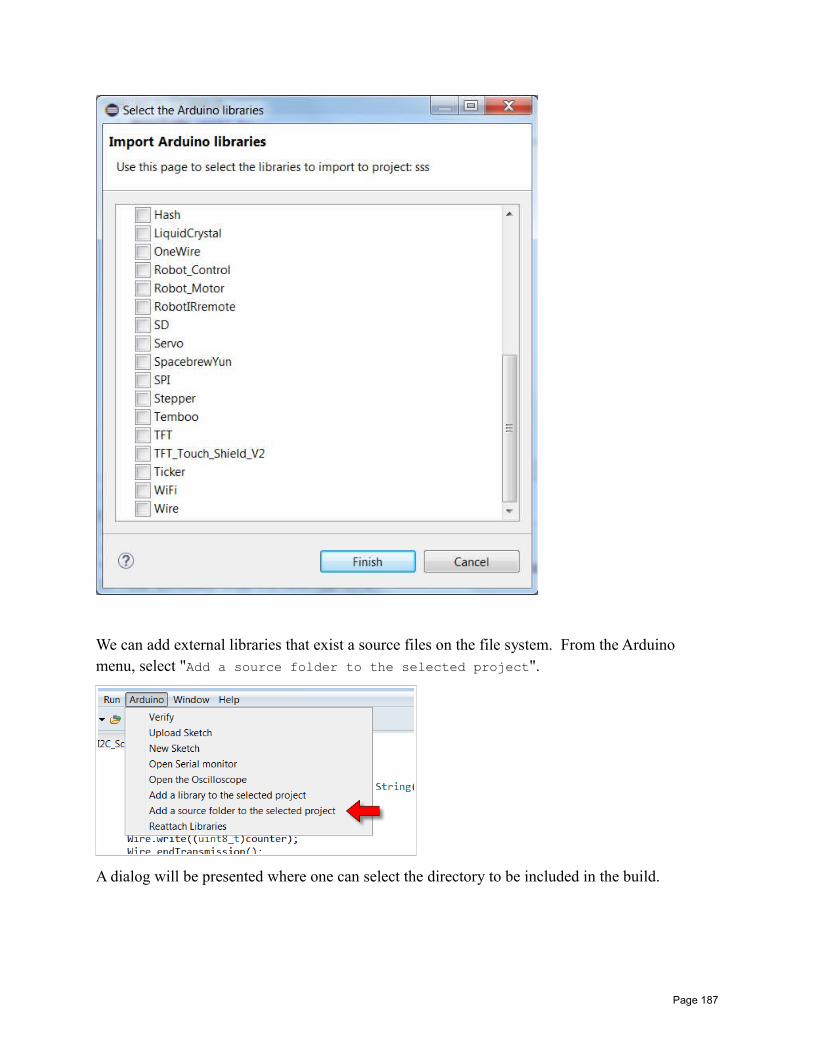
We can add external libraries that exist a source files on the file system. From the Arduino menu, select "Add a source folder to the selected project".
A dialog will be presented where one can select the directory to be included in the build.
Page 187
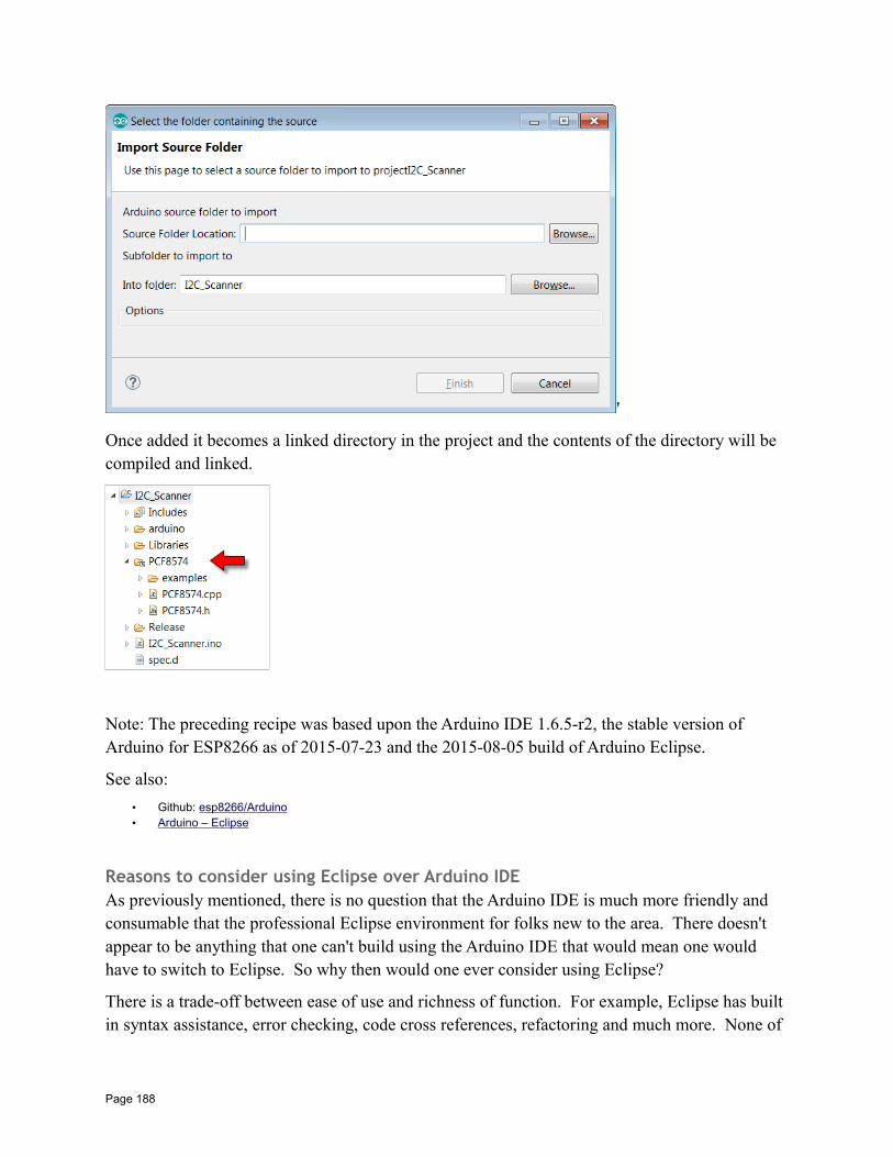
'
Once added it becomes a linked directory in the project and the contents of the directory will be compiled and linked.
Note: The preceding recipe was based upon the Arduino IDE 1.6.5-r2, the stable version of Arduino for ESP8266 as of 2015-07-23 and the 2015-08-05 build of Arduino Eclipse.
See also:
• Github: esp8266/Arduino• Arduino – Eclipse
Reasons to consider using Eclipse over Arduino IDEAs previously mentioned, there is no question that the Arduino IDE is much more friendly and consumable that the professional Eclipse environment for folks new to the area. There doesn't appear to be anything that one can't build using the Arduino IDE that would mean one would have to switch to Eclipse. So why then would one ever consider using Eclipse?
There is a trade-off between ease of use and richness of function. For example, Eclipse has built in syntax assistance, error checking, code cross references, refactoring and much more. None of
Page 188
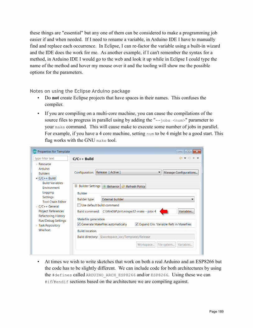
these things are "essential" but any one of them can be considered to make a programming job easier if and when needed. If I need to rename a variable, in Arduino IDE I have to manually find and replace each occurrence. In Eclipse, I can re-factor the variable using a built-in wizard and the IDE does the work for me. As another example, if I can't remember the syntax for a method, in Arduino IDE I would go to the web and look it up while in Eclipse I could type the name of the method and hover my mouse over it and the tooling will show me the possible options for the parameters.
Notes on using the Eclipse Arduino package• Do not create Eclipse projects that have spaces in their names. This confuses the
compiler.
• If you are compiling on a multi-core machine, you can cause the compilations of the source files to progress in parallel using by adding the "--jobs <num>" parameter to your make command. This will cause make to execute some number of jobs in parallel. For example, if you have a 4 core machine, setting num to be 4 might be a good start. Thisflag works with the GNU make tool.
• At times we wish to write sketches that work on both a real Arduino and an ESP8266 but the code has to be slightly different. We can include code for both architectures by using the #defines called ARDUINO_ARCH_ESP8266 and/or ESP8266. Using these we can #if/#endif sections based on the architecture we are compiling against.
Page 189
• As of 2015-08-08, attempting to use native SDK function in the Arduino Eclipse environment does not work if your source files are "*.ino". It appears that "user_include.h" is included automatically with C++ function name mangling in effect.
• I recommend renaming any "*.ino" files in your project to "*.cpp".
Arduino ESP Libraries
The WiFi libraryThe Arduino has a WiFi library for use with its WiFi shield. A library with a similar interface hasbeen supplied for the Arduino environment for the ESP8266.
To use the ESP8266 WiFi library you must include its header:
#include <ESP8266WiFi.h>
To be a station and connect to an access point, execute a call to WiFi.begin(ssid, password). Now we need to to poll WiFi.status(). When this returns WL_CONNECTED, then we are connected to the network.
To set up an access point, we would call WiFi.softAP() supplying the ssid and password information.
Here is an example of us connecting as a station:
WiFi.mode(WIFI_STA);WiFi.begin(SSID, PASSWORD);if (WiFi.waitForConnectResult() != WL_CONNECTED)
Serial1.println("Failed");return;
WiFi.printDiag(Serial1);// We are now connected as a station
See also:
• WiFiClient• WiFiServer• Arduino WiFi library
WiFi.beginStart a WiFi connection as a station.
int begin(const char *ssid,const char *passPhrase=NULL,int32_t channel=0,uint8_t bssid[6]=NULL)
int begin(
Page 190
char *ssid,char *passPhrase=NULL,int32_t channel=0,uint8_t bssid[6]=NULL)
Begin a WiFi connection as a station. The ssid parameter is mandatory but the others can be leftas default. The return value is our current connection status.
WiFi.beingSmartConfigbool beginSmartConfig()
WiFi.beginWPSConfigbool beginWPSConfig()
WiFi.BSSIDRetrieve the current BSSID.
uint8_t BSSID()uint8_t *BSSID(uint8_t networkItem)
Retrieve the current BSSID.
WiFi.BSSIDstrRetrieve the current BSSID as a string representation.
String BSSIDstr()String BSSIDstr(uint8_t networkItem)
Retrieve the current BSSID as a string representation.
WiFi channelRetrieve the current channel.
int32_t channel()int32_t channel(uint8_t networkItem)
Retrieve the current channel.
WiFi.configSet the WiFi connection configuration.
void config(IPAddress local_ip, IPAddress gateway, IPAddress subnet)void config(IPAddress local_ip, IPAddress gateway, IPAddress subnet, IPAddress dns)
Page 191
Set the configuration of the WiFi using static parameters. This disables DHCP.
WiFi.disconnectDisconnect from an access point.
int disconnect(bool wifiOff = false)
Disconnect from the current access point.
WiFi.encryptionTypeReturn the encryption type of the scanned WiFi access point.
uint8_t encryptionType(uint8_t networkItem)
Return the encryption type of the scanned WiFi access point.
The values are one of:
• ENC_TYPE_NONE
• ENC_TYPE_WEP
• ENC_TYPE_TKIP
• ENC_TYPE_CCMP
• ENC_TYPE_AUTO
WiFi.gatewayIPGet the IP address of the station gateway.
IPAddress gatewayIP()
Retrieve the IP address of the station gateway.
WiFi.getNetworkInfoRetrieve all the details of the specified scanned networkItem.
bool getNetworkInfo(uint8_t networkItem,String &ssid,uint8_t &encryptionType,int32_t &RSSI,uint8_t *&BSSID,uint32_t &channel,bool &isHidden)
Retrieve all the details of the specified scanned networkItem.
Page 192
WiFi.hostByNameLookup a host by a name.
int hostByName(const char *hostName, IPAddress &result)
Look up a host by name and get its IP address. This function returns 1 on success and 0 on failure.
WiFi.hostnameRetrieve and set the hostname used by this station.
String hostname()bool hostname(char *hostName)bool hostname(const char *hostName)bool hostname(String hostName)
WiFi.isHiddenDetermine if the scanned network item is flagged as hidden.
bool isHiddem(uint8_t networkItem)
Determine if the scanned network item is flagged as hidden.
WiFi.localIPGet the station IP address.
IPAddress localIP()
Get the IP address for the station. There is a separate IP address if the ESP is an access point.
See also:
• WiFi.softAPIP
WiFi.macAddressGet the station interface MAC address.
uint_t *macAddress(uint8_t *mac)String macAddress()
Get the station interface MAC address.
WiFi.modeSet the operating mode.
void mode(WiFiMode mode)
Set the operating mode of the WiFi. This is one of:
Page 193
• WIFI_OFF – Switch off WiFi
• WIFI_STA – Be a WiFi station
• WIFI_AP – Be a WiFi access point
• WIFI_AP_STA – Be both a WiFi station and a WiFi access point
See also:
• Defining the operating mode
WiFi.printDiagLog the state of the WiFi connection.
void printDiag(Print &dest)
Log the state of the WiFi connection. We can pass in either Serial or Serial1 as an argument to log the data to the Serial port. An example of output is as shown next:
Mode: STAPHY mode: NChannel: 7AP id: 0Status: 5Auto connect: 0SSID (7): yourSSIDPassphrase (8): yourPasswordBSSID set: 0
Note that the status value is the result of a wifi_station_get_connect_status() call.
See also:
• wifi_station_get_connect_status
WiFi.RSSIRetrieve the RSSI value of the scanned network item.
int32_t RSSI(uint8_t networkItem)
Retrieve the RSSI value of the scanned network item.
WiFi.scanCompleteDetermine the status of a previous scan request.
int8_t scanComplete()
If the result is >= 0 then this is the number of WiFi access points found. Otherwise, the value is less than 0 and the codes are:
• SCAN_RUNNING – A scan is currently in progress.
Page 194
• SCAN_FAILD – A scan failed.
See also:
• WiFi.scanNetworks• WiFi.scanDelete
WiFi.scanDeleteDelete the results from a previous scan.
void scanDelete()
Delete the results from a previous scan. A request to scan the network results in the allocation of memory. This call releases that memory.
See also:
• WiFi.scanComplete• WiFi.scanNetworks
WiFi.scanNetworksScan the access points in the environment.
int8_t scanNetworks(bool async = false)
Scan the access points in the environment. We can either perform this synchronous or asynchronous. On a synchronous call, the result is the number of access points found.
See also:
• WiFi.scanComplete• WiFi.scanDelete
WiFi.smartConfigDonebool smartConfigDone()
WiFi.softAPSetup an access point.
void softAP(const char *ssid)void softAP(const char *ssid,
const char *passPhrase,int channel=1,int ssid_hidden=0)
The ssid is used to advertize our network. The passPhrase is the password a station must supply in order to be authorized to access.
Page 195
WiFi.softAPConfigvoid softAPConfig(IPAddress local_ip, IPAddress gateway, IPAddress subnet)
WiFi.softAPdisconnectint softAPdisconnect(bool wifiOff=false)
WiFi.softAPmacAddressGet the MAC address of the access point interface.
uint8_t *softAPmacAddress(uint8_t *mac)
Get the MAC address of the access point interface.
WiFi.softAPIPGet the IP address of the access point interface.
IPAddress softAPIP()
Return the IP address of the access point interface. There is a separate IP for the station.
See also:
• WiFi.localIP
WiFi.SSIDRetrieve the SSID.
char *SSID()const char *SSID(uint8_t networkItem)
Here we retrieve the SSID of the current station or the SSID of the scanned network id.
WiFi.statusRetrieve the current WiFi status.
wl_status_t status()
The status returned will be one of:
• WL_IDLE_STATUS (0)
• WL_NO_SSID_AVAIL (1)
• WL_SCAN_COMPLETED (2)
• WL_CONNECTED (3)
• WL_CONNECT_FAILED (4)
Page 196
• WL_CONNECTION_LOST (5)
• WL_DISCONNECTED (6)
WiFi.stopSmartConfigvoid stopSmartConfig()
WiFi.subnetMaskIPAddress subnetMask()
WiFi.waitForConnectResultWait until the WiFi connection has been formed or failed.
uint8_t waitForConnectResult()
If we are a station, then block waiting for us to become connected or failed. The return code is the status. Specifically, this function watches the status to see when it becomes something other than WL_DISCONNECTED. Perhaps a more positive form of this function would be:
while (WiFi.status() != WL_CONNECTED) delay(500);Serial.print(".");
WiFiClientThis library provides TCP connections to a partner. A separate class provides UDP communications.
To use this library, you must include "ESP8266WiFi.h".
We create an instance of this class and then connect to a partner using the connect() method.
WiFiClient
WiFiClient.availableReturn the amount of data available to be read.l15summe
int available()
Return the amount of data available to be read.
WiFiClient.connectConnect to the given host at the given port using TCP.
Page 197
int connect(const char* host, uint16_t port)int connect(IPAddress ip, uint16_t port)
Connect to the given host at the given port using TCP. This function returns 0 on a failure.
WiFiClient.connectedDetermine if we are connected to a partner.
uint8_t connected()
Return true if connected and false otherwise.
WiFiClient.flushvoid flush()
WiFiClient.getNoDelaybool getNoDelay()
WiFiClient.peekint peek()
WiFiClient.readRead data from the partner.
int read()int read(uint8_t *buf, size_t size)
Read data from the partner. These functions read either a single byte or a sequence of bytes fromthe partner.
WiFiClient.remoteIPRetrieve the remote IP address of the connection.
IPAddress remoteIP()
Retrieve the remote IP address of the connection.
WiFiClient.remotePortReturn the remote port being used in an existing connection.
uint16_t remotePort()
Page 198
Return the remote port being used in an existing connection.
WiFiClient.setLocalPortStartSet the initial port for allocating local ports for connections.
void setLocalPortStart(uint16_t port)
Set the initial port for allocating local ports for connections.
WiFiClient.setNoDelayvoid setNoDelay(bool nodelay)
WiFiClient.statusuint8_t status()
WiFiClient.stopDisconnect a client.
void stop()
Disconnect a client.
WiFiClient.stopAllStop all the connections formed by this WiFi client.
void stopAll()
WiFiClient.writeWrite data to the partner.
size_t write(uint8_t b)size_t write(const uint8_t *buf, size_t size)size_t write(T& source, size_t unitSize);
Write data to the partner. The first function writes one byte, while the second function writes an array of characters.
WiFiServer
WiFiServerCreate an instance of a Server listening on the supplied port.
Page 199
WiFiServer(uint16_t port)
Create an instance of a Server listening on the supplied port. Interesting, it appears that once we crate a server instance within an ESP8266, there is no way to stop it running.
WiFiServer.availableRetrieve a WiFiClient object that can be used for communications.
WiFiClient available(byte* status)
Retrieve the corresponding WiFiClient.
See also:
• WiFiClient
WiFiServer.beginStart listening for incoming connections.
void begin()
Start listening for incoming connections. Until this method is called, the ESP8266 doesn't acceptincoming connections. Interestingly, once called, there is no obvious way to stop listening. The port used for the incoming connections is the one supplied when the WiFiServer object was constructed.
WiFiServer.getNoDelay
WiFiServer.hasClientReturn true if we have a client connected.
bool hasClient()
WiFiServer.setNoDelay
WiFiServer.status
WiFiServer.writeWARNING!! This method is not implemented.
size_t write(uint8_t b)size_t write(const uint8_t *buffer, size_t size)
Although present on the interface, this method is not yet implemented.
Page 200
IPAddressA representation of an IPAddress. This class has some operator overrides:
[i] – Get the ith byte of the address. I should be 0-3.
ESP8266WebServerThe ESP8266WebServer class provides the core implementation of an HTTP server. This is software that responds to browser requests. To use this class we create an instance of an ESP8266WebServer object specifying the TCP port number on which it will listen. The default port for browsers is port 80 so this is a good choice.
Once the object has been created, we define one or more callback functions that will be invoked when a browser connection is received. The function called on() is used to register these. Thesecallback functions are keyed on the URL path requested by the browser. For example, if our ESP8266 is running at IP address 192.168.1.2 and the browser URL is:
http://192.168.1.2/index.html
The the URL path will be "/index.html".
If we wish to send a response to a request at that URL, we would register a callback function using that path as a key.
For example:
myServer.on("/index.html", myFunction);
where myFunction is a C function with the signature:
void myFunction()
The callback function, when called, can use the ESP8266WebServer object to execute a send() method call to send a response.
If a browser request arrives for a URL path that is not explicitly handled, a call to a callback function registered with the onNotFound() method is invoked. This can serve as a catch-all for processing.
When a URL contains query properties of the form "x=y", the number, names and values of theseproperties are available in the args(), argName() and arg() functions. Note that URL encoding is not currently supported so data can not yet contain URL invalid characters.
When a request from a browser is received, one wants to send back a response and the way to achieve that is through an invocation of the send() method. This takes the response code to the browser (200 for OK), the MIME encoding type and the payload of the data as parameters.
When you send a request from a browser to a Web server, anticipate an extra HTTP GET request that wishes to retrieve a file called "/favicon.ico" which is used to specify an icon that
Page 201
represents the web site being accessed. To handle this, we might wish to add a handler function that looks as follows:
webServer.on("/favicon.ico", []() webServer.send(404, "text/plain", "");
);
This registers a handler for the icon file and sends back a 404 (not found) response to the browser. Notice the use of an in-line anonymous function in C++. Your choice to use this style of coding is your own. Personally, I prefer explicitly declared functions.
Here is an example of a Web server app:
#include <ESP8266WiFi.h>#include <WiFiClient.h>#include <ESP8266WebServer.h>
const char *ssid="mySsid";const char *password="myPassword+";
ESP8266WebServer webServer(80);
void logDetails();
void testHandler() Serial1.println("testHandler"); logDetails(); webServer.send(200, "text/plain", "Here is our response: " + String(millis()));
void notFoundHandler() Serial1.println("Not Found Handler"); logDetails();
String methodToString(HTTPMethod method) switch(method)
case HTTP_GET: return "GET"; case HTTP_POST: return "POST"; case HTTP_PUT: return "PUT"; case HTTP_PATCH: return "PATCH"; case HTTP_DELETE: return "DELETE"; return "Unknown";
void logDetails() Serial1.println("URL is: " + webServer.uri()); Serial1.println("HTTP Method on request was: " +
Page 202
methodToString(webServer.method())); // Print how many properties we received and then print their names // and values. Serial1.println("Number of query properties: " + String(webServer.args())); int i; for (i=0; i<webServer.args(); i++) Serial1.println(" - " + webServer.argName(i) + " = " + webServer.arg(i));
void setup() Serial1.begin(115200); Serial1.println("Starting ..."); WiFi.begin(ssid, password); // Wait for connection while (WiFi.status() != WL_CONNECTED) delay(500); Serial1.print("."); Serial1.println(""); Serial1.print("Connected to "); Serial1.println(ssid); Serial1.print("IP address: "); Serial1.println(WiFi.localIP()); webServer.on("/test", testHandler); webServer.on("/favicon.ico", []() webServer.send(404, "text/plain", ""); );
webServer.onNotFound(notFoundHandler); webServer.begin(); Serial1.println("We have started the Web Server");
void loop() webServer.handleClient();
See also:
• Wikipedia: Favicon• ESP8266WebServer.on• ESP8266WebServer.send
ESP8266WebServerConstruct an instance of a WebServer object.
ESP8266WebServer::ESP8266WebServer(int port)
Construct an instance of the class. The port number supplied is the port that will be listened upon for incoming browser requests.
Page 203
ESP8266WebServer.argRetrieve the value of the argument.
String arg(int index)
For a property passed on a query string, here we can retrieve the corresponding value.
ESP8266WebServer.argNameRetrieve the name name of the argument.
String argName(int index)
For a property passed on a query string, here we can retrieve the corresponding name.
ESP8266WebServer.argsRetrieve the number of properties passed on a query string supplied with the browser query.
int args()
ESP8266WebServer.beginStart listening for incoming browser connections.
void begin()
ESP8266WebServer.clientWiFiClient client()
ESP8266WebServer.handleClientHandle a client (browser) request.
void handleClient()
This is the function that is to be periodically called to process incoming browser requests. For example, this is the function that is placed in the body of the loop().
ESP8266WebServer.hasArgReturn true if the named property was supplied.
bool hasArg(const char* name)
The name parameter is the name of the property that may have been supplied as a property in a query string.
Page 204
ESP8266WebServer.methodRetrieve the method supplied by the original browser request.
HTTPMethod method()
The HTTPMethod can be one of:
• HTTP_GET
• HTTP_POST
• HTTP_PUT
• HTTP_PATCH
• HTTP_DELETE
ESP8266WebServer.onRegister callbacks to process browser requests.
void on(const char *uri,ESP8266WebServer::THandlerFunction handler)
void ESP8266WebServer::on(const char *uri,HTTPMethod method,ESP8266WebServer::THandlerFunction handler)
Register a callback function for a URI and method. The first variant of the function will handle amatching URI for all methods while the second allows us to handle callbacks for the same URI part but different HTTP methods.
The handler function has a signature of:
void (handler *)()
ESP8266WebServer.onFileUpload
ESP8266WebServer.onNotFoundRegister a callback when no specific handler otherwise exists.
void onNotFound(THandlerFunction fn)
If no callback has been explicitly registered for an incoming URL request, this callback function will be invoked as a catch-all.
ESP8266WebServer.sendSend a response to the browser.
void send(int code, const char *contentType, const String &content)
Send data to the browser. This is the primary response entry point.
Page 205
The code parameter is the HTTP response code. The code value of 200 means OK. The contentType parameter is the MIME content of the payload. The content parameter is the actual content to send.
ESP8266WebServer.sendContentSend a string to the browser. This is a lower level interface and using the send() method is the correct way to send app data.
void sendContent(const String &content)
Send a string to the browser. The string passed in content is used to transmit the data.
ESP8266WebServer.sendHeaderSend an HTTP header.
void sendHeader(const String& name, const String& value, bool first)
Add an HTTP header to the output stream sent to the browser. The name parameter is the name of the header while value is the value of the header. The first parameter says whether or not the header will be added at the front of the list of headers or at the end.
ESP8266WebServer.setContentLengthSet the length of the content to be sent.
void setContentLength(size_t contentLength)
ESP8266WebServer.streamFileStream the content of a file.
size_t streamFile(T &file, const String &contentType)
ESP8266WebServer.uploadHTTPUpload& upload()
ESP8266WebServer.uriRetrieve the current URI that was supplied by the browser.
String uri()
This is of primary value in a request callback handler where we can determine the relative URI path.
Page 206
ESP8266mDNS libraryAdvertise ourselves via Multicast DNS. The library called "ESP8266mDNS" must be added to the project and the include called "ESP8266mDNS.h" must be included.
Examining this library, it appears to not use the ESP8266 SDK functions for mDNS. That appears odd.
See also:
• Multicast Domain Name Systems
MDNS.addServicevoid addService(char *service, char *proto, uint16_t port);void addService(const char *service, const char *proto, uint16_t port)void addService(String service, String proto, uint16_t port)
MDNS.beginBegin responding to mDNS requests.
bool begin(const char* hostName);bool begin(const char* hostName, IPAddress ip, uint32_t ttl=120)
Note that the version of the function with more than the hostname is implemented by ignoring the other parameters. The function returns true on success.
MDNS.updatevoid update();
I2C – WireThe Wire class provides I2C support. In order to use this class, import "Wire.h" into your sketch. When we use this class, a global instance called "Wire" is made available to us. One wire is called SCL which provides the clock while the other wire is called SDA and is the data bus. On the Arduino, the library supports being either a master or a slave however in the current implementation, only being a master is supported.
To use this class, first we define which pins should be used and then start the service.
Wire.begin(SDApin, SCLpin);
To send data, we begin a transmission using beginTransmission():
Wire.beginTransmission(deviceAddress);
now we can write some data …
Wire.write(value);
Page 207

and finally complete the transmission:
Wire.endTransmission();
if we wish to receive data from the slave, we can call requestFrom():
Wire.requestFrom(deviceAdress, size, true);
and data can be read using the available() and read() functions.
See also:
• Working with I2C• Arduino – Wire Library
Wire.availableDetermine the number of bytes available to read.
int available(void)
Determine the number of bytes available to read.
See also:
• Wire.read• Wire.requestFrom
Wire.beginInitialize the wire library.
void begin(int SDApin, int SCLpin)void begin()void begin(uint8_t address)void begin(int address)
Initialize the wire library. When an address is supplied, we are a slave otherwise we are a master.We can also specify the pins to be used for SDA and SCL. If we are a master and no pins are supplied, we will use the default pins.
WARNING!! – It appears that there is NO support for actually being a slave and only a master issupported at this time.
WARNING!! – In the current code, the address parameter is ignored!!
See also:
• Wire.pins
Wire.beginTransmissionBeging a transmission block to a slave.
void beginTransmission(uint8_t address)void beginTransmission(int address)
Page 208
Begin the notion of sending a transmission to a slave device with the supplied address. Further calls to write() will queue data to be transmitted which is finally executed with a call to endTransmission().
Wire.endTransmissionEnd the bracketing of a transmission.
uint8_t endTransmission(void) // Defaults to sendStop = trueuint8_t endTransmission(uint8_t sendStop)
End the bracketing of a transmission and perform the actual transmit. The return codes are:
• 0 – Transmitted correctly
• 2 – Received NACK on transmit of address
• 3 – Received NACK on transmit of data
• 4 – line busy
Wire.flushDiscard any un-read or un-written data.
void TwoWire::flush(void)
Discard any un-read or un-written data. A call to available() will return 0 and a call to endTransmission() will transmit no data.
Wire.onReceiveA callback when we are in the role of a slave and receive a transmission from a master.
void onReceive( void (*function)(int numBytes))
A callback when slave receives a transmission from a master.
WARNING!! – This function is not implemented.
Wire.onReceiveServiceNot implemented.
void onReceiveService(uint8_t* inBytes, int numBytes)
Not implemented.
WARNING!! – This function is not implemented.
Page 209
Wire.onRequestA callback invoked when we are in the role of a slave and a master requests data from us.
void onRequest(void (*function)(void))
A callback invoked when we are in the role of a slave and a master requests data from us.
WARNING!! – This function is not implemented.
Wire.onRequestServiceNot implemented.
void onRequestService(void)
Not implemented.
WARNING!! – This function is not implemented.
Wire.peekPeek at the next byte.
int peek(void)
Peek at the next byte if one is available. A return of -1 if there is no byte available.
Wire.pinsWARNING!! - This function has been deprecated in favor of begin(sda, scl).
Define the default pins for SDA and SCL.
void pins(int sda, int scl)
Define the default pins for SDA and SCL.
See also:
• Wire.begin
Wire.readRead a single byte.
int read(void)
Read a single byte from the bus. A value of -1 is returned if there is no byte available.
See also:
• Wire.available• Wire.requestFrom
Page 210
Wire.requestFromRequest data from a slave.
size_t requestFrom(uint8_t address, size_t size, bool sendStop)uint8_t requestFrom(uint8_t address, uint8_t quantity, uint8_t sendStop)uint8_t requestFrom(uint8_t address, uint8_t quantity)uint8_t requestFrom(int address, int quantity)uint8_t requestFrom(int address, int quantity, int sendStop)
Request data from a slave. This method should be called when we are playing the role of a master. The address parameter defines the slave address for the device that should respond. If the sendStop is true, a stop message is transmitted releasing the I2C bus. If sendStop is false, a restart message is transmitted preventing another bus master from taking control.
The quantity parameter states how many bytes we wish to receive.
The return value is the number of bytes that were received.
See also:
• Wire.read• Wire.available
Wire.setClockSet the clock frequency.
void setClock(uint32_t frequency)
Set the clock frequency. Always call setClock() AFTER a call to begin().
Wire.writeWrite one or more bytes to the slave.
size_t write(uint8_t data)size_t write(const uint8_t *data, size_t quantity)
Write one or more bytes to the slave.
Ticker libraryThis library sets up callback functions that are called after a period of time. To use this library you must include "Ticker.h". For example:
#include <Ticker.h>
void timerCB() Serial1.println("Tick ...");
void setup()
Page 211
Serial1.begin(115200);ticker.attach(5, timerCB);Serial1.println("Ticker attached");
TickerAn instance of a Ticker object. Commonly this is created as a global such as:
Ticker myTicker;
attachAttach a callback function to the ticker.
void attach(float seconds,callback_t callback)
void attach(float seconds,void (*callback)(TArg),TArg arg)
Attach a callback function to the ticker such that the callback is invoked each period of seconds. Note that seconds is a float so we can specify values such as 0.1 to indicate a callback every 1/10th of a second (100 milliseconds).
The callback_t is a defined as:
void (*callback_t)(void)
attach_msAttach a callback function to the ticker.
void attach_ms(uint32_t milliseconds,callback_t callback)
void attach_ms(uint32_t milliseconds,void (*callback)(TArg), TArg arg)
Attach a callback function to the ticker such that the callback is invoked each period of milliseconds. Only one attachment can be made to a timer.
detachDetach a ticker from the timer.
void detach()
Detach a callback function from the timer. No further callbacks will occur.
onceAttach a callback function to the timer for a one-shot firing.
Page 212
void once(float seconds,callback_t callback)
void once(float seconds,void (*callback)(TArg),TArg arg)
Attach a callback function to the timer for a one-shot firing. Note that seconds is a float so we can specify values such as 0.1 to indicate a callback every 1/10th of a second (100 milliseconds).
once_msAttach a callback function to the timer for a one-shot firing.
void once_ms(uint32_t milliseconds,callback_t callback)
void once_ms(uint32_t milliseconds,void (*callback)(TArg),TArg arg)
Attach a callback function to the timer for a one-shot firing.
EEPROM libraryThis library allows us to store and retrieve data from storage that persists across a device restart. A singleton object called EEPROM is pre-supplied for use.
EEPROM.beginBegin the process of writing or reading from EEPROM. The size is the amount of storage we wish to work with.
void begin(size_t size)
EEPROM.commitThe changes to the data are committed to EEPROM. A return of true indicates success while a return of false indicates a failure.
bool commit()
EEPROM.endCommits the changes to the data and then releases any local storage. No further reads or writes should be attempted until after the next begin() call.
void end()
EEPROM.getRead a data structure from storage.
Page 213
T &get(int address, T &t)
EEPROM.getDataPtrRetrieve a pointer to the storage we are going to read or write.
uint8_t *getDataPtr()
EEPROM.putPut a data structure to storage.
const T &put(int address, const T &t)
EEPROM.readRead a byte from storage.
uint8_t read(int address)
EEPROM.writeWrite a byte to storage.
void write(int address, uint8_t value)
SPIFFSFS is the File System library which provides the ability to read and write files from within the Arduino ESP environment. But wait … read and write files to where? There are no "drives" on an ESP8266. The data for the files is read and written to an area of flash memory and since flashis relatively small in size (4MBytes or so max) then that is an upper bound of maximum size of the cumulative files … however, this is still more than enough for many usage patterns such as saving state, logs or configuration information.
SPIFFS.beginBegin working with the SPIFFS file system.
bool begin()
Returns true of success and false otherwise.
SPIFFS.openOpen the named file.
File open(const char *path, const char *mode)File open(const String &path, const char *mode)
Page 214
The mode defines how we wish to access the file. The options are:
• r – Read the file. The file must exist.
• w – Write to the file. Truncate the file if it exists.
• a – Append to the file.
• r+ – Read and write the file.
• w+ – Read and write the file.
• a+ – Read and write the file.
See also:
• File.close
SPIFFS.openDirOpen a directory.
Dir openDir(const char *path)Dir openDir(const String &path)
SPIFFS.removeRemove/delete a file from the file system.
bool remove(const char *path)bool remove(const String &path)
SPIFFS.renameRename a file.
bool rename(const char *pathFrom, const char *pathTo)bool rename(const String &pathFrom, const String &pathTo)
File.availableReturn the number of bytes that are available within the file from the current file position to its maximum size.
int available()
File.closeClose a previously opened file.
void close()
No further reading nor writing should be attempted to be performed.
Page 215
File.flushFlush the file.
void flush()
File.nameRetrieve the name of the file.
const char *name()
File.peekPeek at the next byte of data in the file without consuming it.
int peek()
File.positionRetrieve the current file pointer position.
size_t position()
File.readRead data from the file.
int read()size_t read(uint8_t *buf, size_t size)
Read either a single byte of data or a buffer of data from the file.
File.seekChange the current file pointer position.
bool seek(uint32_t pos, SeekMode mode)
The mode can be one of:
• SeekSet – Change the file pointer position to the absolute value.
• SeekCur – Change the file pointer position to be relative to the current position.
• SeekEnd – Change the file pointer position to be relative to the end of the file.
File.sizeRetrieve the maximum size of the file.
size_t size()
Page 216
File.writeWrite data to the file.
size_t write(uint8_t c)size_t write(uint8_t *buf, size_t size)
Write either a single byte or a buffer of bytes into the file at the current file pointer position.
Dir.fileNameRetrieve the name of the file.
String fileName()
Dir.nextbool next()
Dir.openFile open(const char *mode)File open(String &path, const char *mode)
Dir.openDirDir openDir(const char *path)Dir openDir(String &path)
Dir.remove
Dir.rename
ESP libraryA class has been provided called ESP that provides ESP8266 environment specific functions. You must realize that using these functions will result in your applications not being portable to the Arduino (if that is a desire).
ESP.deepSleepvoid deepSleep(uint32_t time_us, WakeMode mode)
ESP.eraseConfigbool eraseConfig()
ESP.getBootModeuint8_t getBootMode()
Page 217
ESP.getBootVersionuint8_t getBootVersion()
ESP.getChipIduint32_t getChipId()
ESP.getCpuFreqMHzuint8_t getCpuFreqMHz()
ESP.getCycleCountuint32_t getCycleCount()
ESP.getFlashChipIduint32_t getFlashChipId()
ESP.getFlashChipModeFlashMode_t getFlashChipMode()
ESP.getFlashChipRealSizeuint32_t getFlashChipRealSize()
ESP.getFlashChipSizeuint32_t getFlashChipSize()
ESP.getFlashChipSizeByChipIduint32_t getFlashChipSizeByChipId()
ESP.getFlashChipSpeeduint32_t getFlashChipSpeed()
ESP.getFreeHeapuint32_t getFreeHeap()
Page 218
ESP.getFreeSketchSpaceuint32_t getFreeSketchSpace()
ESP.getResetInfoString getResetInfo()
ESP.getResetInfoPtrstruct rst_info * getResetInfoPtr()
ESP.getSdkVersionRetrieve the string representation of the SDK being used.
const char *getSdkVersion()
ESP.getSketchSizeuint32_t getSketchSize()
ESP.getVccuint16_t getVcc()
ESP.resetvoid EspClass::reset()
ESP.restartvoid EspClass::restart()
ESP.updateSketchbool updateSketch(Stream& in,uint32_t size,bool restartOnFail,bool restartOnSuccess)
Page 219

ESP.wdtDisablevoid wdtDisable()
ESP.wdtEnablevoid wdtEnable(uint32_t timeout_ms)
ESP.wdtFeedvoid wdtFeed()
Page 220
String libraryAlthough it is believed that this library may be identical to the Arduino String library, I believe it is so essential to understand that I am going to list the methods again.
String
ConstructorString(const char *cstr = "");String(const String &str)String(char c)String(unsigned char, unsigned char base = 10)String(int, unsigned char base = 10)String(long, unsigned char base = 10)String(unsigned long, unsigned char base = 10)String(float, unsigned char decimalPlaces = 2)String(double, unsigned char decimalPlaces = 2)
Create an instance of the String class seeded with various data type initializers.
String.c_strRetrieve a C string representation.
const char *c_str()
String.reserveunsigned char reserve(unsigned int size)
String.lengthReturn the length of the string.
unsigned int length()
Return the length of the string.
String.concatunsigned char concat(const String &str)unsigned char concat(const char *cstr)unsigned char concat(char c)unsigned char concat(unsigned char c)unsigned char concat(int num)unsigned char concat(unsigned int num)unsigned char concat(long num)unsigned char concat(unsigned long num)unsigned char concat(float num)unsigned char concat(double num)
String.equalsIgnoreCaseunsigned char equalsIgnoreCase(const String &s) const;
String.startsWithDetermine whether or not this string starts with another string.
Page 221
unsigned char startsWith(const String &prefix)unsigned char startsWith(const String &prefix, unsigned int offset)
String.endsWithunsigned char endsWith(const String &suffix)
String.charAtchar charAt(unsigned int index)
String.setCharAtvoid setCharAt(unsigned int index, char c)
String.getBytesvoid getBytes(unsigned char *buf, unsigned int bufsize, unsigned int index = 0)
String toCharArrayvoid toCharArray(char *buf, unsigned int bufsize, unsigned int index = 0)
String.indexOfFind the position of a string or character within the current string.
int indexOf(char ch)int indexOf(char ch, unsigned int fromIndex)int indexOf(const String &str)int indexOf(const String &str, unsigned int fromIndex)
Find the position of a string or character within the current string. If the match is not found, -1 isreturned otherwise the position of the start of the match is returned.
String.lastIndexOfint lastIndexOf(char ch)int lastIndexOf(char ch, unsigned int fromIndex)int lastIndexOf(const String &str)int lastIndexOf(const String &str, unsigned int fromIndex)
String.substringRetrieve a substring from within the current string.
String substring(unsigned int beginIndex)String substring(unsigned int beginIndex, unsigned int endIndex)
Retrieve a substring from within the current string.
String.replacevoid replace(char find, char replace)void replace(const String& find, const String& replace)
String.removevoid remove(unsigned int index)void remove(unsigned int index, unsigned int count)
String.toLowerCasevoid toLowerCase(void)
String.toUpperCasevoid toUpperCase(void)
Page 222
String.trimvoid trim(void)
String.toIntlong toInt(void)
String.toFloatfloat toFloat(void)
Programming with JavaScriptThe JavaScript is a high level interpreted language. Some of its core constructs are loose typing, object oriented, supports lambda functions, supports closures and, most importantly, has become the language of the web. If one is writing a browser hosted application, then it is a certainty that it will be written in JavaScript. But what of non-browser environments? For a while now JavaScript has been eating into server side code through projects such as node.js. As a language for running server code, it has a significant set of features to realize this capability. Specifically, it supports an event driven architecture paradigm. In JavaScript, we can register functions to be called back upon events being detected. These callbacks can be defined as simple in-line functions on what to do. In these made up examples, we illustrate this:
httpServer.on("/path1", function() // Do something for /path1httpServer.send(response);
);
or
socket.accept(port, function(newSocket) newSocket.on("receive", function(data)
print("We received new data: " + data);newSocket.send("We got the data", function()
newSocket.close(););
););
And if we can implement a good JavaScript model, it maps excellently to the ESP8266 model of the world which is itself event driven via callbacks. This mapping won't be easy … but plans areafoot.
Espruino is an open source project to provide a JavaScript run-time for embedded devices. It hasbeen implemented for the ARM Cortex M3/M4 processors and others.
The question now is … can it be used for the ESP8266? An active project is attempting to do just that. The project is called the "Espruino ESP8266 Project".
See also:
• Espruino• The Espruino ESP8266 Project
Page 223
• Forum thread
Building Espruino-ESPMy C IDE is Eclipse with minGW.
Writing network socket applications using EspruinoThe network library provided by the Espruino environment can be accessed using:
var net = require("net")
This returns a network object that exposes operations necessary to interact with the network. The methods exposed by this object include:
• createServer – Create a server instance
• connect – Connect to a partner
net.connect("http://1.2.3.4:80", function(connection) // Connection is a connection object to a partner.
);
The connection object (which is called a "Socket" by Espruino) is always a reference to a specific connection between the ESP8266 and a partner over the network. The connection objecthas the following methods:
• available – The number of bytes available to read. This will always return 0 if a data listener has been registered.
• read – Read some number of bytes.
• write – Write some number of bytes.
• end – Terminate the connection.
• on("data") – Register a callback to be invoked when data becomes available.
• .
• eWriting network HTTP applications using Espruino
Writing a REST client using EspruinoA REST client is one which sends REST requests which are basically HTTP requests. At a high level, the following example illustrates how to achieve this:
var http = require("http");var getRequest = http.get( host: "192.168.1.9", port: 1817, path: "/sendmessage?message=1" , function(response) // Handle response here
Page 224
);
There are two key parameters to the get() method. The first is an options JavaScript object that configure the details of the REST request. This object includes:
• host – The IP address of the target of the REST request
• port – The port number to which the request will be sent
• path – The relative URL part
• method – Unknown
• headers – JavaScript object representing the headers to send.
The second parameter is a callback function that will be invoked when the response to the REST request is received. The callback function has the signature:
callback(response)
where response is an instance of the Espruino HTTPCRS object. This object has the following methods:
• available – Return the number of available bytes for reading.
• event close – Called when the connection is closed.
• event data – Called when there is data available.
• pipe – Do something with a pipe.
• read – Read available data.
In addition, the response object has a property called headers which are the HTTP response headers returned from the server. These will include the usual HTTP properties which may include:
• Content-Type
• Date
• Connection
• Content-Length
The return from the http.get() function call is an object of type HTTPCRQ.
Working with I2C and JavaScriptThe software I2C mechanism is available from the I2C class which is a built-in. To use, we can leverage an instance of an I2C object. Espruino pre-creates one called I2C1. From there, we can
Page 225
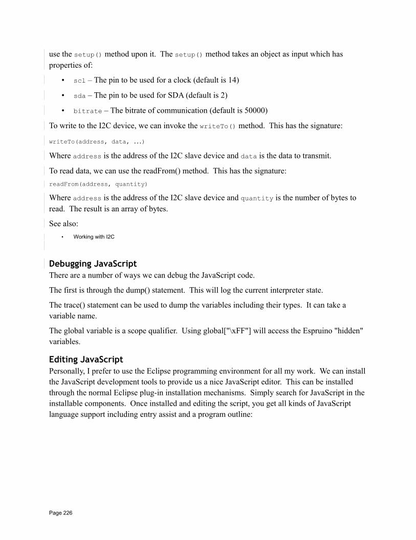
use the setup() method upon it. The setup() method takes an object as input which has properties of:
• scl – The pin to be used for a clock (default is 14)
• sda – The pin to be used for SDA (default is 2)
• bitrate – The bitrate of communication (default is 50000)
To write to the I2C device, we can invoke the writeTo() method. This has the signature:
writeTo(address, data, …)
Where address is the address of the I2C slave device and data is the data to transmit.
To read data, we can use the readFrom() method. This has the signature:
readFrom(address, quantity)
Where address is the address of the I2C slave device and quantity is the number of bytes to read. The result is an array of bytes.
See also:
• Working with I2C
Debugging JavaScriptThere are a number of ways we can debug the JavaScript code.
The first is through the dump() statement. This will log the current interpreter state.
The trace() statement can be used to dump the variables including their types. It can take a variable name.
The global variable is a scope qualifier. Using global["\xFF"] will access the Espruino "hidden" variables.
Editing JavaScriptPersonally, I prefer to use the Eclipse programming environment for all my work. We can installthe JavaScript development tools to provide us a nice JavaScript editor. This can be installed through the normal Eclipse plug-in installation mechanisms. Simply search for JavaScript in the installable components. Once installed and editing the script, you get all kinds of JavaScript language support including entry assist and a program outline:
Page 226
Core JavaScript capabilitiesThe JavaScript language provided by Espruino is covered in detail by the Espruino documentation. However, here are some of the core nuggets that I find extremely useful.
See also:
• Espruino software reference
Running code at intervalsWe can define a timer that will fire either once (setTimeout()) or periodically (setInterval()) and call a function.
The syntax for this is:
setTimeout(function, delay, [args, …])setInterval(function, period, [args, …])
Where delay and period are times measured in milliseconds. Optional arguments can also be supplied which are passed to the function. Both these functions return an id value that can be used to cancel the request before it happens. The function to do this is called clearInterval().
clearInterval(id)
We can also change the interval on a periodic callback with the changeInterval() function.
changeInterval(id, newPeriod)
Page 227
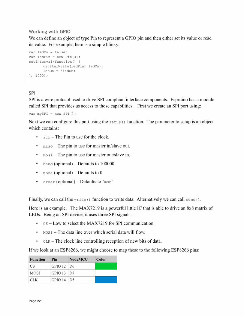
Working with GPIOWe can define an object of type Pin to represent a GPIO pin and then either set its value or read its value. For example, here is a simple blinky:
var ledOn = false;var ledPin = new Pin(4);setInterval(function()
digitalWrite(ledPin, ledOn);ledOn = !ledOn;
, 1000);
SPISPI is a wire protocol used to drive SPI compliant interface components. Espruino has a module called SPI that provides us access to those capabilities. First we create an SPI port using:
var mySPI = new SPI();
Next we can configure this port using the setup() function. The parameter to setup is an object which contains:
• sck – The Pin to use for the clock.
• miso – The pin to use for master in/slave out.
• mosi – The pin to use for master out/slave in.
• baud (optional) – Defaults to 100000.
• mode (optional) – Defaults to 0.
• order (optional) – Defaults to "msb".
Finally, we can call the write() function to write data. Alternatively we can call send().
Here is an example. The MAX7219 is a powerful little IC that is able to drive an 8x8 matrix of LEDs. Being an SPI device, it uses three SPI signals:
• CS – Low to select the MAX7219 for SPI communication.
• MOSI – The data line over which serial data will flow.
• CLK – The clock line controlling reception of new bits of data.
If we look at an ESP8266, we might choose to map these to the following ESP8266 pins:
Function Pin NodeMCU Color
CS GPIO 12 D6
MOSI GPIO 13 D7
CLK GPIO 14 D5
Page 228
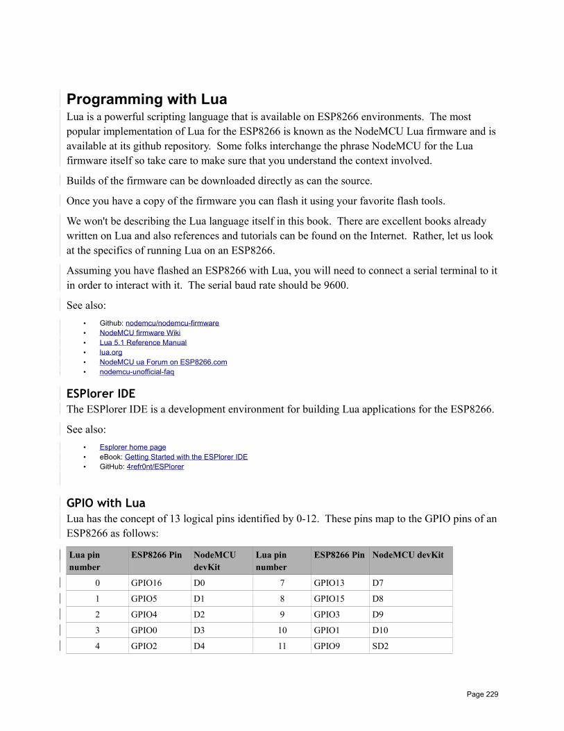
Programming with LuaLua is a powerful scripting language that is available on ESP8266 environments. The most popular implementation of Lua for the ESP8266 is known as the NodeMCU Lua firmware and isavailable at its github repository. Some folks interchange the phrase NodeMCU for the Lua firmware itself so take care to make sure that you understand the context involved.
Builds of the firmware can be downloaded directly as can the source.
Once you have a copy of the firmware you can flash it using your favorite flash tools.
We won't be describing the Lua language itself in this book. There are excellent books already written on Lua and also references and tutorials can be found on the Internet. Rather, let us look at the specifics of running Lua on an ESP8266.
Assuming you have flashed an ESP8266 with Lua, you will need to connect a serial terminal to itin order to interact with it. The serial baud rate should be 9600.
See also:
• Github: nodemcu/nodemcu-firmware• NodeMCU firmware Wiki• Lua 5.1 Reference Manual• lua.org• NodeMCU ua Forum on ESP8266.com• nodemcu-unofficial-faq
ESPlorer IDEThe ESPlorer IDE is a development environment for building Lua applications for the ESP8266.
See also:
• Esplorer home page• eBook: Getting Started with the ESPlorer IDE• GitHub: 4refr0nt/ESPlorer
GPIO with LuaLua has the concept of 13 logical pins identified by 0-12. These pins map to the GPIO pins of anESP8266 as follows:
Lua pin number
ESP8266 Pin NodeMCU devKit
Lua pin number
ESP8266 Pin NodeMCU devKit
0 GPIO16 D0 7 GPIO13 D7
1 GPIO5 D1 8 GPIO15 D8
2 GPIO4 D2 9 GPIO3 D9
3 GPIO0 D3 10 GPIO1 D10
4 GPIO2 D4 11 GPIO9 SD2
Page 229
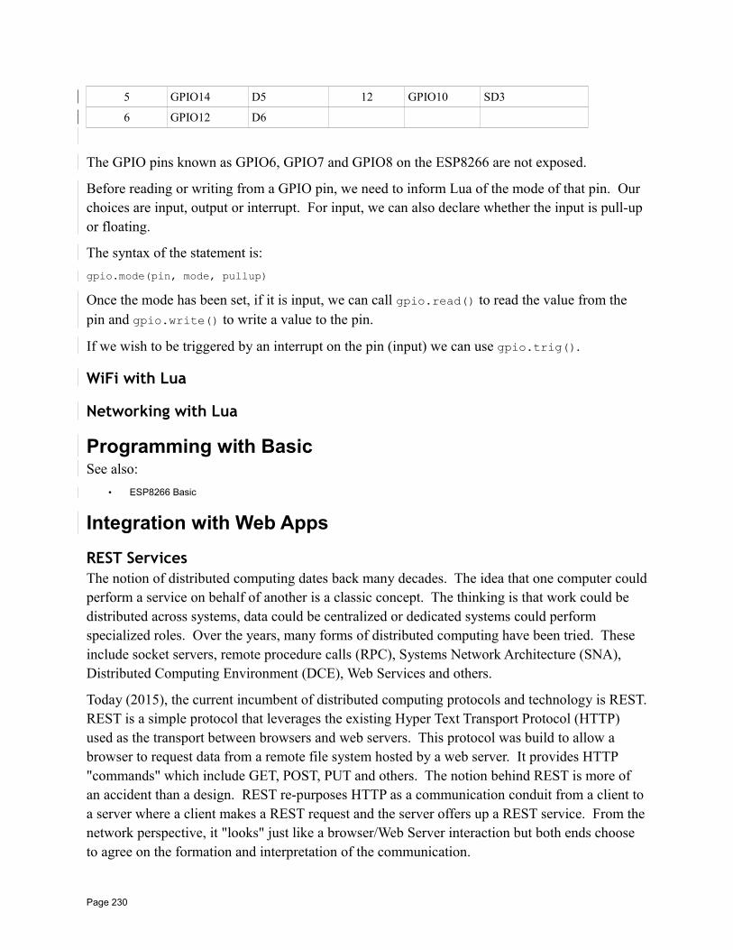
5 GPIO14 D5 12 GPIO10 SD3
6 GPIO12 D6
The GPIO pins known as GPIO6, GPIO7 and GPIO8 on the ESP8266 are not exposed.
Before reading or writing from a GPIO pin, we need to inform Lua of the mode of that pin. Our choices are input, output or interrupt. For input, we can also declare whether the input is pull-up or floating.
The syntax of the statement is:
gpio.mode(pin, mode, pullup)
Once the mode has been set, if it is input, we can call gpio.read() to read the value from the pin and gpio.write() to write a value to the pin.
If we wish to be triggered by an interrupt on the pin (input) we can use gpio.trig().
WiFi with Lua
Networking with Lua
Programming with BasicSee also:
• ESP8266 Basic
Integration with Web Apps
REST ServicesThe notion of distributed computing dates back many decades. The idea that one computer couldperform a service on behalf of another is a classic concept. The thinking is that work could be distributed across systems, data could be centralized or dedicated systems could perform specialized roles. Over the years, many forms of distributed computing have been tried. These include socket servers, remote procedure calls (RPC), Systems Network Architecture (SNA), Distributed Computing Environment (DCE), Web Services and others.
Today (2015), the current incumbent of distributed computing protocols and technology is REST.REST is a simple protocol that leverages the existing Hyper Text Transport Protocol (HTTP) used as the transport between browsers and web servers. This protocol was build to allow a browser to request data from a remote file system hosted by a web server. It provides HTTP "commands" which include GET, POST, PUT and others. The notion behind REST is more of an accident than a design. REST re-purposes HTTP as a communication conduit from a client to a server where a client makes a REST request and the server offers up a REST service. From thenetwork perspective, it "looks" just like a browser/Web Server interaction but both ends choose to agree on the formation and interpretation of the communication.
Page 230
When we add an ESP8266 into the mix, our desire is two-fold. We want the ESP8266 to be able to be a client to external REST service providers and we want the ESP8266 to be the target of clients making REST requests. From the partner perspective, it should be unaware that it is interacting with the ESP8266 as compared to any other computing device.
REST protocolThe REST protocol is built on top of HTTP.
See also:
• RFC7230 – HTTP/1.1 – Message Syntax and Routing• HTTP: The Protocol Every Web Developer Must Know – Part 1
ESP8266 as a REST clientFor the ESP8266 to be a REST client, it must build and transmit HTTP requests to the service provider. This will include building HTTP headers, transmitting the data in a form expected by the provider (eg. JSON, XML or other textual representation) and handling the response from theprovider which may include interpreting the received payload.
To transmit a REST request is composed of two parts. First it opens a TCP connection to the partner and then transmits the HTTP compliant data down that connection. The first part is easy, the second part is more of a challenge. We could read and understand the HTTP spec and build the request part by part but this would have to be done for each project that wishes to use REST client technology. What would be better is if we had a library that "knows" how to make well formed REST requests and we simply leveraged its existing functions.
ESP8266 as a REST service providerFor an ESP8266 to be a REST service provider, basically means that it has to play the role of a Web Server and respond to Web Server requests. However, unlike a simple Web Server which simply retrieves and sends file content as a function of the path on the URL, it is likely that the REST service provider will perform some computation when an HTTP client request arrives. For example, if we attached a temperature sensor to the GPIOs of the ESP8266, when a REST request arrives, the ESP8266 could read the current temperature value and send the encoded result back as a the response to the request.
Being a Web Server basically means listening on a TCP port and when connections arrive, interpreting the data received as HTTP protocol. This would be a lot of work on a project by project basis but thankfully there are a number of pre-written libraries that perform this task for us and all we need concern ourselves with is examination of any parameters passed with the request and performing the logic we wish performed when ever a new request is received.
A library such as ESP8266WebServer would be perfect for this task.
See also:
Page 231
• ESP8266WebServer
TaskerTasker is an Android application that automates and scripts tasks to be executed on an Android device. Using Tasker we can create a task which is defined as a sequence of commands and actions to be executed. Next we can create a Profile which maps an event, that when detected, executes a task. Although this is useful, how does that relate to an ESP8266? Imagine that the event that occurs is an ESP8266 sending a message to your phone. With that notion, an ESP8266 can, effectively, trigger anything that one might be able to do with such a phone. For example, it might make a phone call, send an SMS message or capture a photograph.
See also:
• Tasker home page• YouTube: Tasker 101 Tutorials
AutoRemoteFollowing on from our discussion of Tasker above, we now have an admission. It appears that Tasker does not have the ability to listen for incoming TCP/IP based events and messages. However, because Tasker is extensible and developers can write plug-ins for it, Tasker can be augmented. One such augmentation is the AutoRemote plugin. Using that plugin, a TCP/IP message can then be sent and received by AutoRemote which can then act as a source of events for Tasker.
With AutoRemote configured as a Tasker plugin, we can configure it to listen for HTTP requests.This causes AutoRemote to listen on TCP port number 1817. The data it is listening for is an HTTP request. For example:
http://<phone ip>:1817/sendmessage?message=1
With both Tasker and AutoRemote installed, it will still not be listening for incoming WiFi messages over a local WiFi environment unless we are Internet connected. We must run a TaskerTask called "AutoRemote WiFi".
For example, in Tasker:
1. Create a new profile triggered by Event → System → Device Boot
2. Create a New Task associated with the profile
3. Add an action from Plugin → AutoRemote → Wifi
4. In the configuration for the action, check "Wifi Service"
What this will do is start the Wifi Service whenever the device (Android) boots.
Unfortunately, AutoRemote has a serious drawback. It doesn't allow Tasker to send a response back in the original REST request that might contain data that could be used. For example, if we
Page 232
wish to use AutoRemote to send a request that returned the current GPS location, that is simply not possible.
When an AutoRemote request arrives, it sets a number of variables within the Tasker environment that can be used as parameters to Tasker tasks. These include:
• %armessage
• %arpar()
• %arcomm
• %artime
• %arfiles
• %arsenderbtmac
• %arsenderid
• %arsenderlocalip
• %arsendername
• %arsenderpublicip
• %arsendertype
• %arvia
wifi
See also:
• AutoRemote home page
DuckDNSI anticipate that in most folks houses there is a WiFi access point that either directly or through a modem, connects to the Internet. Since the WiFi access point offers a local network to which theESP8266 can join, we now see that the ESP8266 can reach the outside world through the access point. However, what about the reverse? What if we want a client on the Internet to reach our ESP8266. How could we achieve that?
Page 233
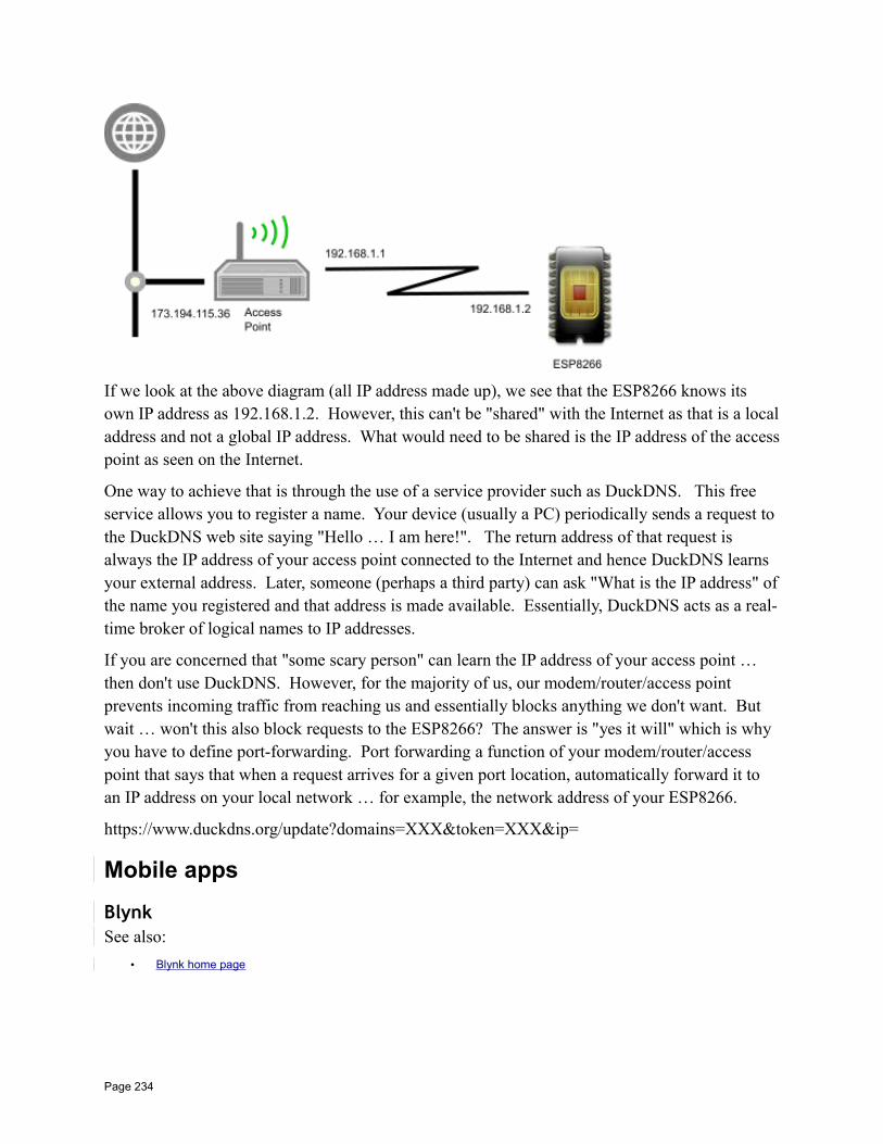
If we look at the above diagram (all IP address made up), we see that the ESP8266 knows its own IP address as 192.168.1.2. However, this can't be "shared" with the Internet as that is a localaddress and not a global IP address. What would need to be shared is the IP address of the accesspoint as seen on the Internet.
One way to achieve that is through the use of a service provider such as DuckDNS. This free service allows you to register a name. Your device (usually a PC) periodically sends a request to the DuckDNS web site saying "Hello … I am here!". The return address of that request is always the IP address of your access point connected to the Internet and hence DuckDNS learns your external address. Later, someone (perhaps a third party) can ask "What is the IP address" ofthe name you registered and that address is made available. Essentially, DuckDNS acts as a real-time broker of logical names to IP addresses.
If you are concerned that "some scary person" can learn the IP address of your access point … then don't use DuckDNS. However, for the majority of us, our modem/router/access point prevents incoming traffic from reaching us and essentially blocks anything we don't want. But wait … won't this also block requests to the ESP8266? The answer is "yes it will" which is why you have to define port-forwarding. Port forwarding a function of your modem/router/access point that says that when a request arrives for a given port location, automatically forward it to an IP address on your local network … for example, the network address of your ESP8266.
https://www.duckdns.org/update?domains=XXX&token=XXX&ip=
Mobile apps
BlynkSee also:
• Blynk home page
Page 234
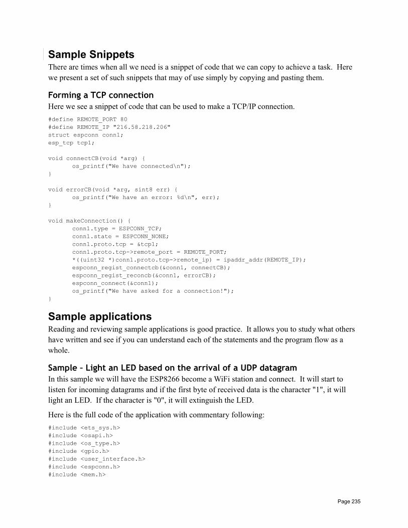
Sample SnippetsThere are times when all we need is a snippet of code that we can copy to achieve a task. Here we present a set of such snippets that may of use simply by copying and pasting them.
Forming a TCP connectionHere we see a snippet of code that can be used to make a TCP/IP connection.
#define REMOTE_PORT 80#define REMOTE_IP "216.58.218.206"struct espconn conn1;esp_tcp tcp1;
void connectCB(void *arg) os_printf("We have connected\n");
void errorCB(void *arg, sint8 err) os_printf("We have an error: %d\n", err);
void makeConnection() conn1.type = ESPCONN_TCP;conn1.state = ESPCONN_NONE;conn1.proto.tcp = &tcp1;conn1.proto.tcp->remote_port = REMOTE_PORT;*((uint32 *)conn1.proto.tcp->remote_ip) = ipaddr_addr(REMOTE_IP);espconn_regist_connectcb(&conn1, connectCB);espconn_regist_reconcb(&conn1, errorCB);espconn_connect(&conn1);os_printf("We have asked for a connection!");
Sample applicationsReading and reviewing sample applications is good practice. It allows you to study what others have written and see if you can understand each of the statements and the program flow as a whole.
Sample – Light an LED based on the arrival of a UDP datagramIn this sample we will have the ESP8266 become a WiFi station and connect. It will start to listen for incoming datagrams and if the first byte of received data is the character "1", it will light an LED. If the character is "0", it will extinguish the LED.
Here is the full code of the application with commentary following:
#include <ets_sys.h>#include <osapi.h>#include <os_type.h>#include <gpio.h>#include <user_interface.h>#include <espconn.h>#include <mem.h>
Page 235
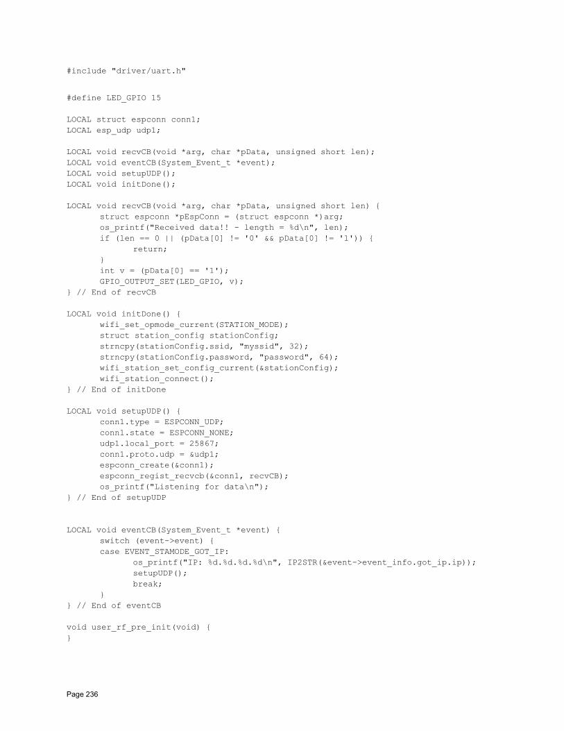
#include "driver/uart.h"
#define LED_GPIO 15
LOCAL struct espconn conn1;LOCAL esp_udp udp1;
LOCAL void recvCB(void *arg, char *pData, unsigned short len);LOCAL void eventCB(System_Event_t *event);LOCAL void setupUDP();LOCAL void initDone();
LOCAL void recvCB(void *arg, char *pData, unsigned short len) struct espconn *pEspConn = (struct espconn *)arg;os_printf("Received data!! - length = %d\n", len);if (len == 0 || (pData[0] != '0' && pData[0] != '1'))
return;int v = (pData[0] == '1');GPIO_OUTPUT_SET(LED_GPIO, v);
// End of recvCB
LOCAL void initDone() wifi_set_opmode_current(STATION_MODE);struct station_config stationConfig;strncpy(stationConfig.ssid, "myssid", 32);strncpy(stationConfig.password, "password", 64);wifi_station_set_config_current(&stationConfig);wifi_station_connect();
// End of initDone
LOCAL void setupUDP() conn1.type = ESPCONN_UDP;conn1.state = ESPCONN_NONE;udp1.local_port = 25867;conn1.proto.udp = &udp1;espconn_create(&conn1);espconn_regist_recvcb(&conn1, recvCB);os_printf("Listening for data\n");
// End of setupUDP
LOCAL void eventCB(System_Event_t *event) switch (event->event) case EVENT_STAMODE_GOT_IP:
os_printf("IP: %d.%d.%d.%d\n", IP2STR(&event->event_info.got_ip.ip));setupUDP();break;
// End of eventCB
void user_rf_pre_init(void)
Page 236
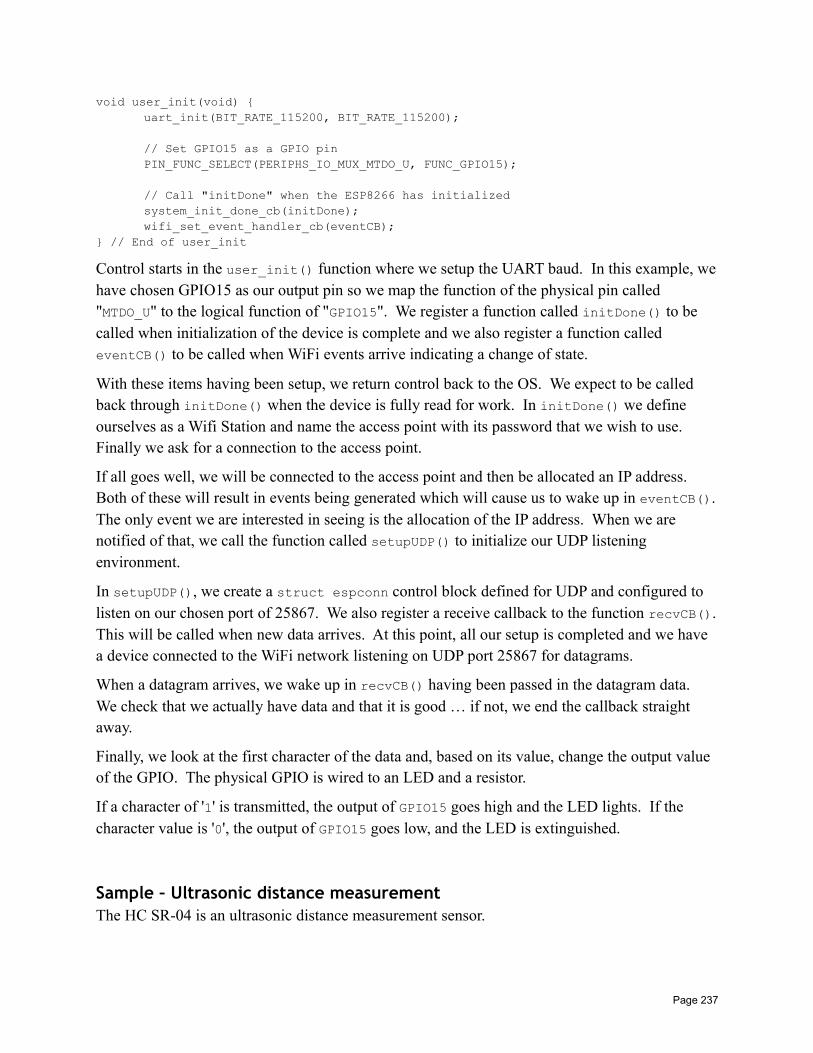
void user_init(void) uart_init(BIT_RATE_115200, BIT_RATE_115200);
// Set GPIO15 as a GPIO pinPIN_FUNC_SELECT(PERIPHS_IO_MUX_MTDO_U, FUNC_GPIO15);
// Call "initDone" when the ESP8266 has initializedsystem_init_done_cb(initDone);wifi_set_event_handler_cb(eventCB);
// End of user_init
Control starts in the user_init() function where we setup the UART baud. In this example, wehave chosen GPIO15 as our output pin so we map the function of the physical pin called "MTDO_U" to the logical function of "GPIO15". We register a function called initDone() to be called when initialization of the device is complete and we also register a function called eventCB() to be called when WiFi events arrive indicating a change of state.
With these items having been setup, we return control back to the OS. We expect to be called back through initDone() when the device is fully read for work. In initDone() we define ourselves as a Wifi Station and name the access point with its password that we wish to use. Finally we ask for a connection to the access point.
If all goes well, we will be connected to the access point and then be allocated an IP address. Both of these will result in events being generated which will cause us to wake up in eventCB().The only event we are interested in seeing is the allocation of the IP address. When we are notified of that, we call the function called setupUDP() to initialize our UDP listening environment.
In setupUDP(), we create a struct espconn control block defined for UDP and configured to listen on our chosen port of 25867. We also register a receive callback to the function recvCB().This will be called when new data arrives. At this point, all our setup is completed and we have a device connected to the WiFi network listening on UDP port 25867 for datagrams.
When a datagram arrives, we wake up in recvCB() having been passed in the datagram data. We check that we actually have data and that it is good … if not, we end the callback straight away.
Finally, we look at the first character of the data and, based on its value, change the output value of the GPIO. The physical GPIO is wired to an LED and a resistor.
If a character of '1' is transmitted, the output of GPIO15 goes high and the LED lights. If the character value is '0', the output of GPIO15 goes low, and the LED is extinguished.
Sample – Ultrasonic distance measurementThe HC SR-04 is an ultrasonic distance measurement sensor.
Page 237
Send a minimum of a 10us pulse to Trig (low to high to low). Later, Echo will go low/high/low.The time that Echo is high is the time it takes the sonic pulse to reach a back-end and bounce back.
Speed of sound is 340.29 m/s (340.29 * 39.3701 inches/sec). Call this Vsound.
If Techo is the time for echo response then d = (Techo * Vsound) / 2.
Also the equation for expected Techo lengths is given by:
Techo = 2d/Vsound
For example:
Distance Time
1cm 2 * 0.01 / 340 = 0.058 msecs = 59 usecs
10cm 2 * 0.1 / 340 = 0.59 msecs = 590 usecs
1m 2 * 1 /340 = 5.9 msecs = 5900 usecs (5.9 msecs)
Page 238
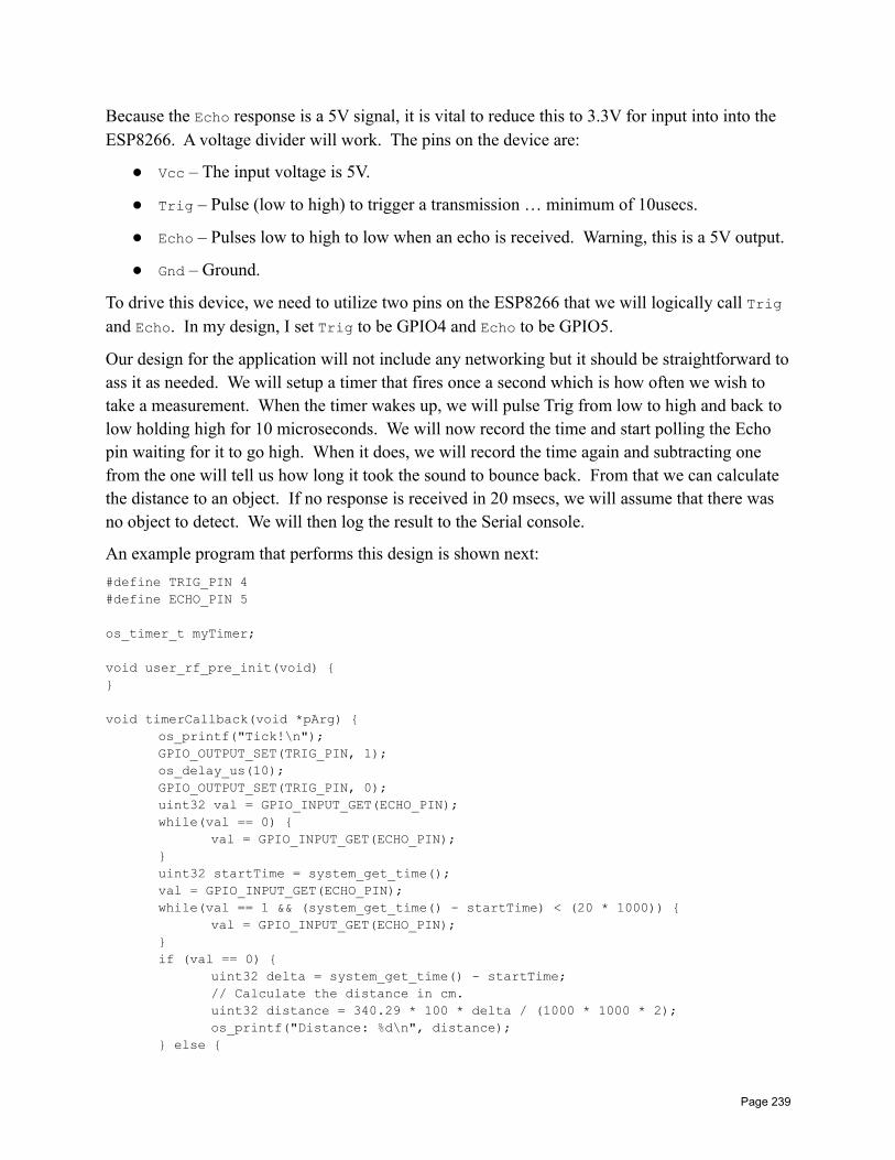
Because the Echo response is a 5V signal, it is vital to reduce this to 3.3V for input into into the ESP8266. A voltage divider will work. The pins on the device are:
Vcc – The input voltage is 5V.
Trig – Pulse (low to high) to trigger a transmission … minimum of 10usecs.
Echo – Pulses low to high to low when an echo is received. Warning, this is a 5V output.
Gnd – Ground.
To drive this device, we need to utilize two pins on the ESP8266 that we will logically call Trig and Echo. In my design, I set Trig to be GPIO4 and Echo to be GPIO5.
Our design for the application will not include any networking but it should be straightforward toass it as needed. We will setup a timer that fires once a second which is how often we wish to take a measurement. When the timer wakes up, we will pulse Trig from low to high and back to low holding high for 10 microseconds. We will now record the time and start polling the Echo pin waiting for it to go high. When it does, we will record the time again and subtracting one from the one will tell us how long it took the sound to bounce back. From that we can calculate the distance to an object. If no response is received in 20 msecs, we will assume that there was no object to detect. We will then log the result to the Serial console.
An example program that performs this design is shown next:
#define TRIG_PIN 4#define ECHO_PIN 5
os_timer_t myTimer;
void user_rf_pre_init(void)
void timerCallback(void *pArg) os_printf("Tick!\n");GPIO_OUTPUT_SET(TRIG_PIN, 1);os_delay_us(10);GPIO_OUTPUT_SET(TRIG_PIN, 0);uint32 val = GPIO_INPUT_GET(ECHO_PIN);while(val == 0)
val = GPIO_INPUT_GET(ECHO_PIN);uint32 startTime = system_get_time();val = GPIO_INPUT_GET(ECHO_PIN);while(val == 1 && (system_get_time() - startTime) < (20 * 1000))
val = GPIO_INPUT_GET(ECHO_PIN);if (val == 0)
uint32 delta = system_get_time() - startTime;// Calculate the distance in cm.uint32 distance = 340.29 * 100 * delta / (1000 * 1000 * 2);os_printf("Distance: %d\n", distance);
else
Page 239
os_printf("No echo!\n");
// End of timerCallback
void user_init(void) uart_init(BIT_RATE_115200, BIT_RATE_115200);// Setup ultrasonics pins as GPIOsetAsGpio(TRIG_PIN);setAsGpio(ECHO_PIN);setupBlink(15);// Set the trigger pin to be default lowGPIO_OUTPUT_SET(TRIG_PIN, 0);os_timer_setfn(&myTimer, timerCallback, NULL);os_timer_arm(&myTimer, 1000, 5);
// End of user_init
Once this has been written and tested, we will make a second pass at the puzzle but this time using an interrupt to trigger the response to the echo.
See also:
• GPIOs
Sample – WiFi ScannerA WiFi scanner is an application which periodically scans for available WiFi networks and shows them to the user. In our design, we will scan periodically and remember the set of networks we find. When we perform re-scans, we will check to see if each of the networks located is a network we have previously seen and, if not, list it to the user. We will also keep a "last seen" time for each network and if a network has not been seen for a minute, then we will forget about it such that if it appears again, we will once more list it to the user.
To illustrate our design, we will break the solution into a number of parts. The first part will be to register a callback function that is called every 30 seconds. This callback will be responsible for requesting a WiFi scan using wifi_station_scan(). This takes a callback function which itself will be invoked when the scan is complete.
When the scan completes, we will have a new list of detected networks. We will walk this list and for each network detected, determine if we have seen it before. If we have, we will update the last seen time. If not, we will add it to the list of previously seen networks and log it to the user.
A second timer callback will run once a minute and will walk the list of previously seen networks. If any of them are older than a minute, we will remove them.
See also:
• Scanning for access points
Page 240
Sample – Working with micro SD cardsA micro SD card is a small portable storage device that can host gigabytes of data. Through the use of an adapter, a micro SD card can be leveraged in conjunction with an ESP8266 providing read and write access to data that persists across ESP8266 restarts.
Sample – Playing audio from an eventIn this sample, we wish an event to be detected by the ESP8266 which, when it happens, causes an audio file to be played.
Sample LibrariesThere are times when commonly used functions can be captured and reused over and over. This section describes just such a set of functions which have been collected. The source for these functions has been placed in Github at <location to be provided>.
The functions, when compiled, are placed in a library called libcommon.a. This can then be linked within your Makefile so that unresolved references to these functions can be satisfied.
A header file called "common.h" is all that one needs to add into your own applications.
Function list
authModeToStringGiven an AUTH_MODE, return a string representation of the mode.
char *authModeToString(AUTH_MODE mode)
checkErrorCheck a return code for an error.
void checkError(sint8 err)
Check the err code for an error and if it is one, log it.
delayMillisecondsDelay for a period of milliseconds.
void delayMilliseconds(uint32 milliseconds)
The milliseconds parameters is the number of milliseconds to delay before returning.
Page 241
dumpBSSINFODump an instance of struct bss_info to the log.
void dumpBSSINFO(struct bss_info *bssInfo)
dumpEspConnDump to the log a decoded representation of the struct espconn.
void dumpEspConn(struct espconn *pEspConn)
dumpRestartDump the restart information to the log.
void dumpRestart()
See also:
• Exception handling
dumpStateDump the WiFi station state to the log.
void dumpState()
See also:
• system_print_meminfo• system_get_free_heap_size• system_get_boot_version• system_get_userbin_addr• system_get_boot_mode• system_get_flash_size_map• system_get_sdk_version()
errorToStringGiven an error code, return a string representation of it.
char *errorToString(sint8 err)
eventLoggerWrite a WiFi event to the log.
void eventLogger(System_Event_t *event)
We can register this function as a callback for a WiFi event. Write the event data to the log.
See also:
• Handling WiFi events• wifi_set_event_handle_cb
Page 242
eventReasonToStringConvert an event reason to a string representation.
char *eventReasonToString(int reason)
Some of the WiFi event callbacks can return a reason value that is an encoding of the reason that something failed. This function returns a string representation of the int value code.
flashSizeAndMapToStringReturn a string representation of the flash size and map.
char *flashSizeAndMapToString()
setAsGpioSet a pin to be used as a GPIO.
void setAsGpio(uint8 pin)
Set the GPIO supplied as pin to be GPIO function.
See also:
• GPIOs
setupBlinkSetup a blinking LED on the given pin.
void setupBlink(uint8 blinkPin)
The blinkPin parameter is the pin to use for blinking.
toHexConvert an array of bytes to a hex string.
uint8 *toHex(uint8 *ptr, int size, uint8 *buffer)
Convert the bytes pointed to by ptr for size bytes into a hex string. The buffer parameter will be where the result will be stored. It must be 2 * size + 1 bytes in length (or more). Each byte is 2 hex characters plus a single byte NULL terminator at the end. The function returns the start of the buffer.
Page 243
API ReferenceNow we have a mini reference to the syntax of many of the ESP8266 exposed APIs. Do not use this reference exclusively. Please also refer to the published Espressif SDK Programming Guide.
Some acronyms and other names are used in the naming of APIs and may need some explanationto fully appreciate them:
• dhcpc – DHCP client
• dhcps – DHCP server
• softap – Access point implemented in software
• wps – WiFi Protected Setup
• sntp – Simple Network Time Protocol
• mdns – Multicast Domain Name System
• uart – Universal asynchronous receiver/transmitter
• pwm – Pulse width modulation
Timer functionsTimer functions allow us to register functions that will be executed at a time in the future or periodically after time passes. We also group functions that manipulate or retrieve time values inthis set.
os_timer_armEnable a millisecond granularity timer.
void os_timer_arm(os_timer_t *pTimer,uint32_t milliseconds,bool repeat)
Arm a timer such that is starts ticking and fires when the clock reaches zero.
The pTimer parameter is a pointed to a timer control structure.
The milliseconds parameter is the duration of the timer measured in milliseconds.
The repeat parameter is whether or not the timer will restart once it has reached zero.
Includes:
• osapi.h
See also:
• Timers and time• os_timer_disarm• os_timer_setfn
Page 244
os_timer_disarmDisarm/Cancel a previously armed timer.
void os_timer_disarm(os_timer_t *pTimer)
Stop a previously started timer which was started by a call to os_timer_arm().
The pTimer parameter is a pointer to a timer control structure.
Includes:
• osapi.h
See also:
• Timers and time• os_timer_arm• os_timer_setfn
os_timer_setfnDefine a function to be called when the timer fires
void os_timer_setfn(os_timer_t *pTimer,os_timer_func_t *pFunction,void *pArg)
Define the callback function that will be called when the timer reaches zero.
The pTimer parameters is a pointer to the timer control structure.
The pFunction parameters is a pointer to the callback function.
The pArg parameter is a value that will be passed into the called back function.
The callback function should have the signature:
void (*functionName)(void *pArg)
The pArg parameter is the value registered with the callback function.
Includes:
• osapi.h
See also:
• Timers and time• os_timer_arm• os_timer_disarm
system_timer_reinit Used to set a micro second timer
Page 245
os_timer_arm_usEnable a micro second timer
hw_timer_initInitialize a hardware timer
hw_timer_armSet the trigger delay
hw_timer_set_funcSet the timer callback
System Functions
system_restore Reset some system settings to defaults
system_restartRestart the system.
void system_restart()
system_init_done_cbRegister a function to be called when system initialization is complete
void system_init_done_cb(init_done_cb_t callbackFunction)
This function is designed only be called in user_init(). It will register a function to be called one time after the ESP8266 has been initialized. The init_done_cb_t defines a function:
void (*functionName)(void)
See also:
• Custom programs
system_get_chip_idGet the id of the chip
long system_get_chip_id()
Page 246
For example: 0xf94322
system_get_vdd33Measure voltage
Unknown … but related to analog to digital conversion.
See also:
• Analog to digital conversion• system_adc_read
system_adc_readRead the A/D converter value.
uint16 system_adc_read()
Read the value of the analog to digital converter. The granularity is 1024 discrete steps.
See also:
• Analog to digital conversion
system_deep_sleepPuts the device to sleep for a period of time.
void system_deep_sleep(uint32 microseconds)
system_deep_sleep_set_optionDefine what the chip will do when it next wakes up.
bool system_deep_sleep_set_option(uint8 option)
system_phys_set_rfoptionEnable the RF after waking up from a sleep (or not)
system_phys_set_max_tpwSet the maximum transmission power
system_phys_set_tpw_via_vdd33Set the transmission power as a function of voltage
Page 247
system_set_os_printTurn on or off logging.
void system_set_os_print(unint8 onOff)
A value of 0 switches it off while a value of 1 switches it on. It was initially thought that this controlled OS level logging however it seems to control all logging via os_printf().
Includes:
• user_interface.h
See also:
• os_printf• os_install_putc1• Logging to UART1
system_print_meminfoPrint memory information
void system_print_meminfo()
Memory information for diagnostics is written to the output stream which is commonly UART1. The format of the data looks as follows:
data : 0x3ffe8000 ~ 0x3ffe853c, len: 1340rodata: 0x3ffe8540 ~ 0x3ffe8af0, len: 1456bss : 0x3ffe8af0 ~ 0x3fff1c18, len: 37160heap : 0x3fff1c18 ~ 0x3fffc000, len: 41960
The .data section is where global and static local initialized variables are kept.
The .rodata section is where read-only global and static data is kept.
The .bss is where un-initialized global and local static data is kept.
The .heap is where the heap of the program can be found.
See also:
• Wikipedia – .bss• Wikipedia – Data segment
system_show_mallocDebug potential memory leak issues.
void system_show_malloc()
This API should also be enabled by explicitly defining MEMLEAK_DEBUG.
The documentation on this function in the SDK programming guide provides a number of warnings and caveats that are not yet fully understood so use with caution.
Page 248

system_get_free_heap_sizeGet the size of the available memory heap
int system_get_free_heap_size()
For example "40544".
See also:
• os_malloc• os_free
system_os_taskSetup a task for execution at a later time.
bool system_os_task(os_task_t task,uint8 priority,os_event_t *queue,uint queueLength)
The "os_task_t" is a pointer to a task handler function which has the signature:
void (*functionName)(os_event_t *event)
This function is defined to be a task handler that will receive all the different post notifications ofthe same priority level.
The os_event_t is a structure which contains:
• os_signal_t signal
• os_param_t param
Both of these are unsigned 32bit integers.
The priority field is the priority of the task request. Three values are defined:
• USER_TASK_PRIO_0
• USER_TASK_PRIO_1
• USER_TASK_PRIO_2
The return is true on success and false on failure.
Includes:
• user_interface.h
See also:
• Task handling• system_os_post
system_os_postPost a message to a task.
Page 249
bool system_os_post(uint8 priority,os_signal_t signal,os_param_t parameter)
Post a message to a task. The task will not run immediately but will run as soon as it can.
The priority field is the priority of the task request. Three values are defined – USER_TASK_PRIO_0, USER_TASK_PRIO_1 and USER_TASK_PRIO_2.
The signal parameter is used by the task handler to determine who should process the signal. Itis actually a uint32_t.
The parameter parameter is used to pass in optional data to the handler.
The return is true on success and false on failure.
Includes:
• user_interface.h
See also:
• Task handling• system_os_task
system_get_timeGet the system time. This is measured in microseconds since last device startup.
uint32 system_get_time()
This timer will roll over after 71 minutes.
Includes:
• <Include missing for this function>
See also:
• Timers and time
system_get_rtc_timeGet the real time clock cycles.
uint32 system_get_rtc_time()
Retrieve the number of real-time clock cycles. For example, if the value returned by system_rtc_clock_cali_proc() is 5.75µS then if the system_get_rtc_time() returns 100, then 575µS of wall clock time has passed since the clock was started.
system_rtc_clock_cali_procClock calibration.
Page 250
uint32 system_rtc_clock_cali_proc(void)
Retrieve the real time clock calibration. This is the wall clock duration of a clock cycle measured in micro seconds. The 16 bit number returned has bits 11-0 representing the value after the decimal point. We can multiply the value returned here against the number of cycles since a previous restart and determine an elapsed wall clock value.
system_rtc_mem_writeStorage space for saving data during a deep sleep in RTC storage.
system_rtc_mem_readRead data from RTC available storage.
system_uart_swapSwap serial UARTs
system_uart_de_swapGo back to original UART
system_get_boot_versionThe version of the boot loader.
uint8 system_get_boot_version()
The current value returned through testing of my devices is "5".
system_get_userbin_addrGet the address of user bin
uint32 system_get_userbin_addr()
The current value returned on my devices is 0x0.
system_get_boot_modeGet the current boot mode
uint8 system_get_boot_mode()
The return value indicates the current boot mode and will be one of:
Page 251
• SYS_BOOT_ENHANCE_MODE – 0
• SYS_BOOT_NORMAL_MODE – 1
On my devices, the value being returned is "0".
system_restart_enhanceRestarts the system in enhanced boot mode
system_update_cpu_freqSet the CPU frequency
void system_update_cpu_freq(int freq)
Set the CPU frequency. Either 80 or 160.
system_get_cpu_freqGet the current CPU frequency
int system_get_cpu_freq()
Returns the CPU frequency in MHz. The value will either be 80 or 160.
system_get_flash_size_mapGet current flash size and map
enum flash_size_map system_get_flash_size_map()
The value returned is an enum which has the following definitions:
• FLASH_SIZE_4M_MAP_256_256
• FLASH_SIZE_2M
• FLASH_SIZE_8M_MAP_512_512
• FLASH_SIZE_16M_MAP_512_512
• FLASH_SIZE_32M_MAP_512_512
• FLASH_SIZE_16M_MAP_1024_1024
• FLASH_SIZE_32M_MAP_1024_1024
See also:
• Loading a program into the ESP8266
Page 252
system_get_rst_infoInformation about the current startup.
struct rst_info* system_get_rst_info()
Retrieve information about the current device startup.
Includes:
• user_interface.h
See also:
• Exception handling• struct rst_info
system_get_sdk_version()Return the version of the SDK
char *system_get_sdkVersion()
For example "1.1.1".
system_soft_wdt_feedFeed the software watchdog.
void system_soft_wdt_feed()
Feed the software watchdog. The function is only of value when the software watchdog is enabled. If we need to perform looping within our code, we need to call this function periodically so that we don't starve the WiFi runtime. The motif here is starve and food and hence the notion of a watchdog timer that checks that we don't spend too long away from WiFi … so we must feed the dog. Interesting metaphors.
However … experiments are showing that it doesn't seem to actually DO anything. The mystery of its purpose continues. See: http://bbs.espressif.com/viewtopic.php?f=7&t=1055
system_soft_wdt_stopDisable the software watchdog.
void system_soft_wdt_stop()
Stop the software watchdog. It is recommended not to stop this timer for too long (8 seconds or less) otherwise the hardware watchdog will force a reset.
See also:
• Watchdog timer
Page 253
system_soft_wdt_restartRestart the software watchdog.
void system_soft_wdt_restart()
Restart the software watchdog following a previous call to stop it.
See also:
• Watchdog timer
os_memsetSet the values of memory
void os_memset(void *pBuffer, int value, size_t size)
Set the memory pointed to by pBuffer to the value for size bytes.
Includes:
• osapi.h
See also:
• Working with memory• os_memcpy
os_memcmpCompare two regions of memory.
int os_memcmp(uint8 *ptr1, uint8 *ptr2, int size)
Compare two regions of memory. The return is 0 if they are equal.
Includes:
• osapi.h
os_memcpyCopy the values of memory.
void os_memcpy(void *destination, void *source, size_t size)
Copy the memory from the buffer pointed to by source to the buffer pointed to by destinationfor the number of bytes specified by size.
Includes:
• osapi.h
See also:
• Working with memory
Page 254
• os_memset
os_mallocAllocate storage from the heap.
void *malloc(size_t size)
Allocate size bytes from the heap and return a pointer to the allocated storage.
Includes:
• mem.h
See also:
• Working with memory• os_zalloc• os_free
os_callocAllocate storage for a set of elements.
void *calloc(size_t num, size_t size)
Here we allocate num instances of size sized objects in contiguous memory.
Includes:
• mem.h
os_reallocReallocate a previously obtained chunk of memory with a new size.
void *os_realloc(void *buf, size_t newSize)
Includes:
• mem.h
os_zallocAllocate storage from the heap and zero its values.
void *os_zalloc(size_t size)
Allocate size bytes from the heap and return a pointer to the allocated storage. Before returning, the storage area is zeroed.
Includes:
• mem.h
Page 255
See also:
• Working with memory• os_malloc• os_free
os_freeRelease previously allocated storage back to the heap.
void os_free(void *pBuffer)
Release the storage previously allocated by os_malloc() or os_zalloc() back to the heap.
Includes:
• mem.h
See also:
• Working with memory• os_malloc• os_zalloc
os_bzeroSet the values of memory to zero.
void os_bzero(void *pBuffer, size_t size)
Sets the data pointer to by pBuffer to zero for size bytes.
Includes:
• osapi.h
See also:
• Working with memory
os_delay_usDelay for microseconds.
void os_delay_us(uint16 us)
Delay for a maximum interval of 65535 microseconds.
Includes:
• osapi.h
See also:
• Timers and time• system_set_os_print
Page 256
os_printfPrint a string to UART.
void os_printf(char *format, …)
The format flags that are known to work include:
• %d – display a decimal
• %ld – display a long decimal
• %x – display as a hex number
• %s – display as a string
• "\n" – display a newline (includes a prefixed carriage return)
The output text is sent to the function registered with os_install_putc1(). By default, this is UART0 but can be changed to UART1 by setting the uart1_write_char() function.
Includes:
• osapi.h
See also:
• Debugging• os_install_putc1• system_set_os_print
os_install_putc1Register a function print a character
void os_install_putc1(void (*pFunc)(char c));
Register a function that will be called by output functions such as os_printf() that will log output. For example, this can be used to write to the serial ports. When a call is made to the supplied uart_init() method, the writing function is set to write to UART1.
Includes:
• osapi.h
See also:
• os_printf• system_set_os_print
os_randomunsigned long os_random()
Includes:
• osapi.h
Page 257
os_get_randomint os_get_random(unsigned char *buf, size_t len)
Includes:
• osapi.h
os_strlenGet the length of a string.
int os_strlen(char *string)
Return the length of the null terminated string.
Includes:
• osapi.h
os_strcatConcatenate two strings together.
char *os_strcat(char *str1, char *str2)
Concatenate the null terminated sting pointed to by str1 with the string pointed to by str2 and store the result at str1.
Includes:
• osapi.h
os_strchrIncludes:
• osapi.h
os_strcmpCompare two strings.
int os_strcmp(char *str1, char *str2)
Compare the null terminated string pointed to by str1 with the null terminated string pointed to by str2. If str1 < str2 then the return is < 0. If str1 > str2 then the return is > 0 otherwise they are equal and the return is 0.
Includes:
Page 258
• osapi.h
os_strcpyCopy one string to another.
char *os_strcpy(char *dest, char *src)
Copy the null terminated string pointed to by src to the memory located at dest.
Includes:
• osapi.h
os_strncmpIncludes:
• osapi.h
os_strncpyCopy one string to another but be sensitive to the amount of memory available in the target buffer.
char *os_strncpy(char *dest, char *source, size_t sizeOfDest)
Understand that the resulting string in dest may not be null terminated.
Includes:
• osapi.h
os_sprintfsprintf(char * buffer, char *format, ...)
The format is not as rich as normal sprintf() in a C library. For example, no float or double support.
Includes:
• osapi.h
os_strstrIncludes:
• osapi.h
Page 259
SPI FlashThe SPI Flash apis allow us to read, write and erase sectors contained within flash memory. Note that there is a specific document from Espressif that covers the SPI Flash functions exclusively.
spi_flash_get_idGe the ID info of SPI flash
uint32 spi_flash_get_id(void)
This is a bit encoded value that represents information about the flash chip being used in conjunction with the ESP8266.
The esptool also includes a command (flash_id) that can be used to retrieve and display the flash information.
Includes:
• spi_flash.h
See also:
• esptool.py
spi_flash_erase_sectorErase a flash sector. Each sector is 4k in size.
SpiFlashOpResult spi_flasg_erase_sector(uint16 sec)
Includes:
• spi_flash.h
See also:
spi_flash_writeWrite data to flash
SpiFlashOpResult spi_flash_write(uint32 destAddr, uint32 *srcAddr, unit32 size)
Includes:
• spi_flash.h
See also:
spi_flash_readRead data from flash
SpiFlashOpResult spi_flash_read(uint32 src_addr, uint32 des_addr, uint32 size)
Page 260
Includes:
• spi_flash.h
See also:
spi_flash_set_read_funcvoid spi_flash_set_read_func(user_spi_flash_read read)
Includes:
• spi_flash.h
See also:
system_param_save_with_protectMemory saving
bool system_param_save_with_protect(unit16 start_sec, void *param, uint16 len)
Includes:
• spi_flash.h
See also:
system_param_loadRead data saved with flash protection
bool system_param_load(uint16 start_sec, uint16 offset, void *param, unit16 len)
Includes:
• spi_flash.h
See also:
WifiThe Wifi function provide access to the Wifi capabilities of the device.
wifi_get_opmodeGet the operating mode of the WiFi
uint8 wifi_get_opmode()
Return the current operating mode of the device.
There are threefour values defined:
Page 261
• NULL_MODE – Null mode. (0)
• STATION_MODE – Station mode. (1)
• SOFTAP_MODE – Soft Access Point (AP) mode. (2)
• STATIONAP_MODE – Station + Soft Access Point (AP) mode. (3)
Includes:
• user_interface.h
See also:
• Defining the operating mode• wifi_get_opmode_default• wifi_set_opmode• wifi_set_opmode_current
wifi_get_opmode_defaultGet the default operating mode
uint8 wifi_get_opmode_default()
Return the default operating mode of the device following startup.
There are three values defined:
• STATION_MODE – Station mode
• SOFTAP_MODE – Soft Access Point (AP) mode
• STATIONAP_MODE – Station + Soft Access Point (AP) mode
Includes:
• user_interface.h
See also:
• Defining the operating mode• wifi_get_opmode• wifi_set_opmode• wifi_set_opmode_current
wifi_set_opmodeSet the operating mode of the WiFi including saving to flash.
bool wifi_set_opmode(uint8 opmode)
There are three values defined:
• STATION_MODE – Station mode
• SOFTAP_MODE – Soft Access Point (AP) mode
Page 262
• STATIONAP_MODE – Station + Soft Access Point (AP) mode
Includes:
• user_interface.h
See also:
• Defining the operating mode• wifi_get_opmode• wifi_get_opmode_default• wifi_set_opmode_current
wifi_set_opmode_currentSet the operating mode of the WiFi but don't save to flash.
bool wifi_set_opmode_current(uint8 opmode)
There are three values defined:
• STATION_MODE – Station mode
• SOFTAP_MODE – Soft Access Point (AP) mode
• STATIONAP_MODE – Station + Soft Access Point (AP) mode
Includes:
• user_interface.h
See also:
• Defining the operating mode• wifi_get_opmode• wifi_get_opmode_default• wifi_set_opmode
wifi_set_broadcast_ifbool wifi_set_broadcast_if(uint8 interface)
Includes:
• user_interface.h
See also:
• Broadcast with UDP
wifi_get_broadcast_ifuint8 wifi_get_broadcast_if()
Includes:
Page 263
• user_interface.h
See also:
• Broadcast with UDP
wifi_set_event_handle_cbDefine a callback function to sense WiFi events.
void wifi_set_event_handler_cb(wifi_event_handler_cb_t callbackFunction)
Registers a function to be called when an event is detected by the WiFi subsystem. The signatureof the registered callback function is:
void (*functionName)(System_Event_t *event)
Includes:
• user_interface.h
See also:
• Handling WiFi events• System_Event_t
wifi_get_ip_infoRetrieve the current IP info about the station.
bool wifi_get_ip_info(uint8 if_index,struct ip_info *info)
The if_index parameter defines the interface to retrieve. Two values are defined:
• STATION_IF – 0 – The station interface
• SOFTAP_IF – 1 – The Soft Access Point interface
The info parameter is populated with details of the current ip address, netmask and gateway.
Includes:
• user_interface.h
See also:
• Current IP Address, netmask and gateway• struct ip_info
wifi_set_ip_infoSet the interface data for the device.
bool wifi_set_ip_info(uint8 if_index, struct ip_info *info)
Page 264
The if_index parameter defines the interface to retrieve. Two values are defined:
• STATION_IF – 0 – The station interface
• SOFTAP_IF – 1 – The Soft Access Point interface
The info parameter is a pointer to a struct ip_info that contains the values we wish to set.
Includes:
• user_interface.h
See also:
• Current IP Address, netmask and gateway• struct ip_info
wifi_set_macaddrSet the MAC address.
bool wifi_set_macaddr(uint8 if_index, uint8 *macaddr)
A MAC address is 6 bytes.
Includes:
• user_interface.h
wifi_get_macaddrGet the MAC address.
bool wifi_get_macaddr(uint8 if_index, uint8 *macaddr)
A MAC address is 6 bytes.
Includes:
• user_interface.h
wifi_set_sleep_typeIncludes:
• user_interface.h
wifi_get_sleep_typeIncludes:
• user_interface.h
Page 265
wifi_status_led_installAssociate a GPIO pin with the WiFi status LED.
void wifi_status_led_install(uint8 gpio_id,uint32 mux_name,uint8 gpio_func)
When WiFi traffic flows, we may wish a status LED to flicker or blink indicating flowing traffic.This function allows us to specify a GPIO that should be pulsed to indicate WiFi traffic.
The gpio_id parameter is the numeric pin number.
The mux_name is the name of the multiplexer logical name.
The gpio_func is the function to be enabled for that multiplexer.
Includes:
• user_interface.h
See also:
• wifi_status_led_uninstall
wifi_status_led_uninstallDisassociate a status LED from a GPIO pin.
void wifi_status_led_uninstall()
Disassociates a previous association setup with a call to wifi_status_led_install().
Includes:
• user_interface.h
See also:
• wifi_status_led_install
wifi_station_get_configGet the current station configuration
bool wifi_station_get_config(struct station_config *config)
Retrieve the current station configuration settings.
Includes:
• user_interface.h
See also:
• Station configuration• station_config
Page 266
wifi_station_get_config_defaultGet the default station configuration
Includes:
• user_interface.h
See also:
• Station configuration
wifi_station_set_configSet the configuration of the station.
bool wifi_station_set_config(struct station_config *config)
This function can only be called when the device mode includes Station support. Specifically, the details of which access point to interact with are supplied here. The details are persisted across a restart of the device.
A return value of true indicates success and a value of false indicates failure.
Includes:
• user_interface.h
See also:
• Station configuration• station_config
wifi_station_set_config_currentSet the configuration of the station but don't save to flash.
bool wifi_station_set_config_current(struct station_config *config)
This function can only be called when the device mode includes Station support. Specifically, the details of which access point to interact with are supplied here. The details are not persisted across a restart of the device.
A return value of true indicates success and a value of false indicates failure.
Includes:
• user_interface.h
See also:
• Station configuration• station_config
Page 267
wifi_station_connectConnect the station to an access point.
bool wifi_station_connect()
If we are already connected to a different access point then we first need to disconnect from it using wifi_station_disconnect(). There is also an auto connect attribute which can be used to allow the device to attempt to connect to the last access point seen when it is powered on. This can be set with the wifi_station_set_auto_connect() function.
Includes:
• user_interface.h
See also:
• Connecting to an access point• wifi_station_disconnect• wifi_station_set_auto_connect• wifi_station_get_auto_connect
wifi_station_disconnectDisconnect the station from an access point.
bool wifi_station_disconnect()
We should presume that we have previously connected via a wifi_station_connect(). We can determine our current connection status through wifi_station_get_connect_status().
The return is true on success and false on an error.
Includes:
• user_interface.h
See also:
• wifi_station_connect• wifi_station_get_connect_status
wifi_station_get_connect_statusGet the connection status of the station.
uint8 wifi_station_get_connect_status()
The result is an enum with the following possible values:
Page 268
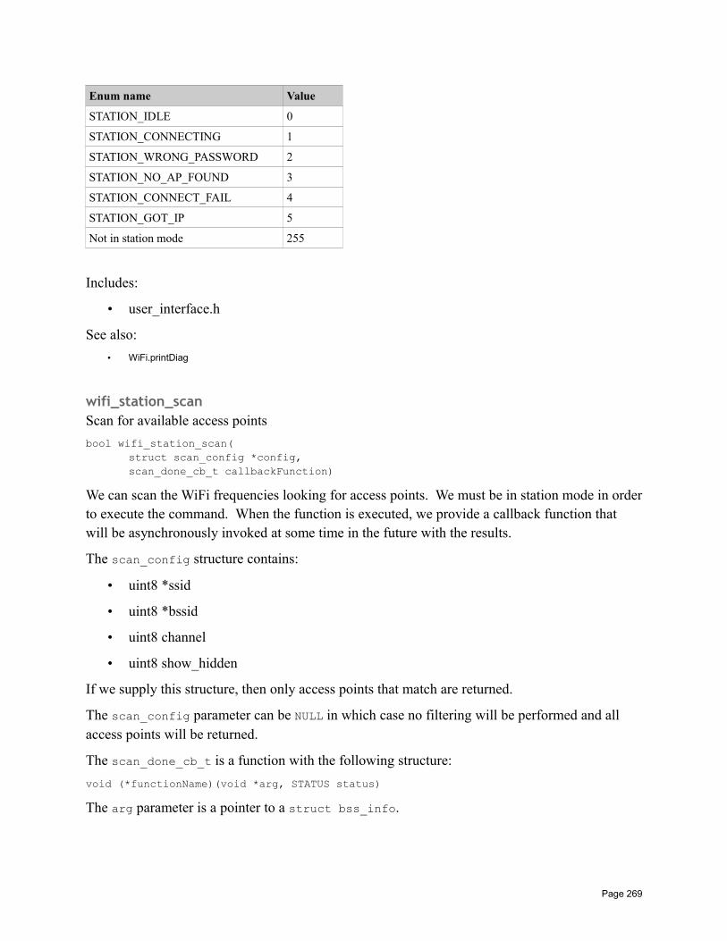
Enum name Value
STATION_IDLE 0
STATION_CONNECTING 1
STATION_WRONG_PASSWORD 2
STATION_NO_AP_FOUND 3
STATION_CONNECT_FAIL 4
STATION_GOT_IP 5
Not in station mode 255
Includes:
• user_interface.h
See also:
• WiFi.printDiag
wifi_station_scanScan for available access points
bool wifi_station_scan(struct scan_config *config,scan_done_cb_t callbackFunction)
We can scan the WiFi frequencies looking for access points. We must be in station mode in orderto execute the command. When the function is executed, we provide a callback function that will be asynchronously invoked at some time in the future with the results.
The scan_config structure contains:
• uint8 *ssid
• uint8 *bssid
• uint8 channel
• uint8 show_hidden
If we supply this structure, then only access points that match are returned.
The scan_config parameter can be NULL in which case no filtering will be performed and all access points will be returned.
The scan_done_cb_t is a function with the following structure:
void (*functionName)(void *arg, STATUS status)
The arg parameter is a pointer to a struct bss_info.
Page 269
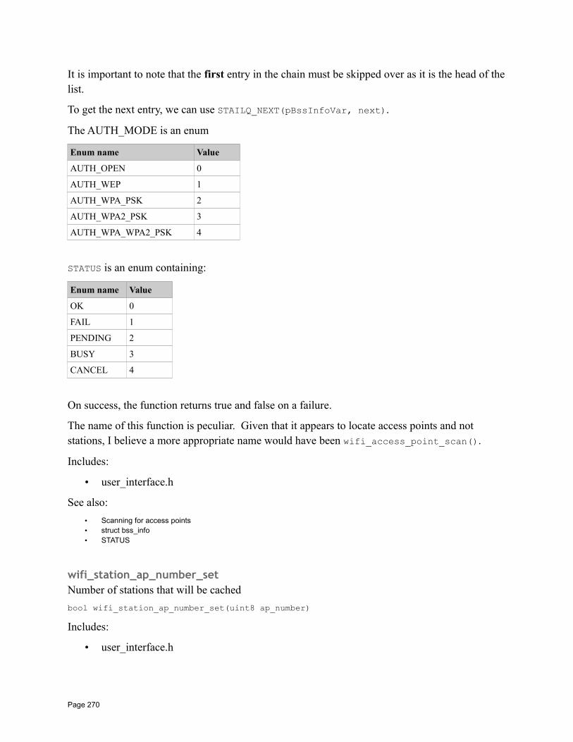
It is important to note that the first entry in the chain must be skipped over as it is the head of thelist.
To get the next entry, we can use STAILQ_NEXT(pBssInfoVar, next).
The AUTH_MODE is an enum
Enum name Value
AUTH_OPEN 0
AUTH_WEP 1
AUTH_WPA_PSK 2
AUTH_WPA2_PSK 3
AUTH_WPA_WPA2_PSK 4
STATUS is an enum containing:
Enum name Value
OK 0
FAIL 1
PENDING 2
BUSY 3
CANCEL 4
On success, the function returns true and false on a failure.
The name of this function is peculiar. Given that it appears to locate access points and not stations, I believe a more appropriate name would have been wifi_access_point_scan().
Includes:
• user_interface.h
See also:
• Scanning for access points• struct bss_info• STATUS
wifi_station_ap_number_setNumber of stations that will be cached
bool wifi_station_ap_number_set(uint8 ap_number)
Includes:
• user_interface.h
Page 270
wifi_station_get_ap_infoGet the information of access points cached
uint8 wifi_station_get_ap_info(struct station_config configs[])
Includes:
• user_interface.h
wifi_station_ap_changeChange the connection to another access point
bool wifi_station_ap_change(uint newApId)
Includes:
• user_interface.h
wifi_station_current_ap_idGet the current access point id
uint8 wifi_station_get_current_ap_id()
Includes:
• user_interface.h
wifi_station_get_auto_connectDetermine whether or not the ESP will auto connect to the last access point on boot.
unit8 wifi_station_get_auto_connect()
Determine whether or not the device will attempt to auto-connect to the last access point on restart. A value if 0 means it will not while non 0 means it will.
Includes:
• user_interface.h
See also:
• wifi_station_connect• wifi_station_disconnect• wifi_station_set_auto_connect
wifi_station_set_auto_connectSet whether or not the ESP will auto connect to the last access point on boot.
Page 271
bool wifi_station_set_auto_connect(uint8 setValue)
Set whether or not the device will attempt to auto-connect to the last access point on restart. A value of 0 means it will not while a non 0 value means it will. If called in user_init(), the setting will be effective immediately. If called elsewhere, the setting will take effect on next restart.
Includes:
• user_interface.h
See also:
• wifi_station_connect• wifi_station_disconnect• wifi_station_get_auto_connect
wifi_station_dhcpc_startStart the DHCP client.
bool wifi_station_dhcpc_start()
If DHCP is enabled, then the IP, netmask and gateway will be retrieved from the DHCP server while if disabled, we will be using static values.
Includes:
• user_interface.h
See also:
• Current IP Address, netmask and gateway• wifi_set_ip_info• wifi_station_dhcpc_stop
wifi_station_dhcpc_stopStop the DHCP client
bool wifi_station_dhcpc_stop()
If DHCP is enabled, then the IP, netmask and gateway will be retrieved from the DHCP server while if disabled, we will be using static values.
Includes:
• user_interface.h
See also:
• Current IP Address, netmask and gateway• wifi_set_ip_info• wifi_station_dhcpc_start
Page 272
wifi_station_dhcpc_statusGet the DHCP client status
enum dhcp_status wifi_station_dhcpc_status()
One of:
• DHCP_STOPPED
• DHCP_STARTED
Includes:
• user_interface.h
wifi_station_set_reconnect_policyWhat should happen when the ESP gets disconnected from the AP
bool wifi_station_set_reconnect_policy(bool set)
Includes:
• user_interface.h
wifi_station_get_rssiGet the received signal strength indication (rssi).
sint8 wifi_station_get_rssi()
Get the received signal strength indication (rssi).
Includes:
• user_interface.h
wifi_station_set_hostnameSet the DHCP hostname of the WiFi device.
bool wifi_station_set_hostname(char *name)
Includes:
• user_interface.h
wifi_station_get_hostnameGet the DHCP hostname of the WiFi device.
char* wifi_station_get_hostname()
Includes:
Page 273
• user_interface.h
wifi_softap_get_configRetrieve the current softAP configuration details.
bool wifi_softap_get_config(struct softap_config *pConfig)
When called, the struct softap_config pointed to be pConfig will be filled in with the detailsof the current softAP configuration. The details returned are those actually in use and may differ from the ones saved for default.
A value of 1 will be returned on success and 0 otherwise.
Includes:
• user_interface.h
See also:
• struct softap_config• wifi_softap_get_config_default• wifi_softap_set_config• wifi_softap_set_config_current
wifi_softap_get_config_defaultRetrieve the default softAP configuration details.
bool wifi_softap_get_config_default(struct softap_config *config)
When called, the struct softap_config pointed to be pConfig will be filled in with the detailsof the default softAP configuration. The details returned are those used at boot and may be different from the ones currently in use.
A value of 1 will be returned on success and 0 otherwise.
Includes:
• user_interface.h
See also:
• struct softap_config• wifi_station_get_config• wifi_softap_set_config• wifi_softap_set_config_current
wifi_softap_set_configSet the current and default softAP configuration.
bool wifi_softap_set_config(struct softap_config *config)
Page 274
When called, the struct softap_config pointed to be pConfig will be used as the details of the default and current softAP configuration.
A value of 1 will be returned on success and 0 otherwise.
Includes:
• user_interface.h
See also:
• struct softap_config• wifi_station_get_config• wifi_softap_get_config_default• wifi_softap_set_config_current
wifi_softap_set_config_currentSet the default softAP configuration.
bool wifi_softap_set_config_current(struct softap_config *config)
When called, the struct softap_config pointed to be pConfig will be used as the details of the current softAP configuration but will not be saved as default.
Includes:
• user_interface.h
See also:
• struct softap_config• wifi_station_get_config• wifi_softap_get_config_default• wifi_softap_set_config
wifi_softap_get_station_numReturn the count of stations currently connected.
uint8 wifi_softap_get_station_num()
Returns the number of stations currently connected. The maximum number of connections on anESP8266 is 4 but we can reduce this in the softAP configuration if needed.
Includes:
• user_interface.h
See also:
• Being an access point• wifi_softap_get_station_info
Page 275
wifi_softap_get_station_infoReturn the details of all connected stations.
struct station_info *wifi_softap_get_station_info()
The return data is a linked list of struct station_info data structures.
Includes:
• user_interface.h
See also:
• Being an access point• wifi_softap_get_station_num• wifi_softap_free_station_info
wifi_softap_free_station_infoRelease the data associated with a struct station_info.
void wifi_softap_free_station_info()
Following a call to wifi_softap_get_station_info() we may have data returned to us. The data was allocated by the OS and we must return it with this function call. Note that this function does not take in the data that was returned.
Includes:
• user_interface.h
See also:
• Being an access point• wifi_softap_get_station_info
wifi_softap_dhcps_startStart the DHCP server service.
bool wifi_softap_dhcps_start()
Start the DHCP server service inside the device.
Includes:
• user_interface.h
See also:
• The DHCP server• wifi_softap_dhcps_stop• wifi_softap_set_dhcps_lease• wifi_softap_dhcps_status• wifi_softap_dhcps_offer_option
Page 276
wifi_softap_dhcps_stopStop the DHCP server service.
bool wifi_softap_dhcps_stop()
Stop the DHCP server service inside the device.
Includes:
• user_interface.h
See also:
• The DHCP server• wifi_softap_dhcps_start• wifi_softap_set_dhcps_lease• wifi_softap_dhcps_status• wifi_softap_dhcps_offer_option
wifi_softap_set_dhcps_leaseDefine the IP address range that will be leased by this DHCP server.
bool wifi_softap_set_dhcps_lease(struct dhcps_lease *pLease)
The pLease parameter is a pointer to a struct dhcps_lease which contains an IP address range of IP addresses that will be leased by this DHCP server. The difference between the upper and lower bound of the IP addresses must be 100 or less. This function will not take effect until the DHCP server is stopped and restarted (assuming it is already running).
Includes:
• user_interface.h
See also:
• The DHCP server• wifi_softap_dhcps_start• wifi_softap_dhcps_stop• wifi_softap_dhcps_status• wifi_softap_dhcps_offer_option• struct dhcps_lease
wifi_softap_get_dhcps_lease
wifi_softap_set_dhcps_lease_timeSet the DHCP server lease time.
bool wifi_softap_set_dhcps_lease_time(uint32 minutes)
Set how long a DHCP IP address lease is good for. the default is 120 minutes. The parameter is the number of minutes that the lease should be held. It has an allowable range of 1-2880.
See also:
• wifi_softap_get_dhcps_lease_time
Page 277
wifi_softap_get_dhcps_lease_timeGet the DHCP server lease time value.
uint32 wifi_softap_get_dhcps_lease_time()
Return the number of minutes that a server DHCP lease IP address will be held.
See also:
• wifi_softap_set_dhcps_lease_time
wifi_softap_reset_dhcps_lease_timeReset the DHCP server lease time to the default value.
bool wifi_softap_reset_dhcps_lease_time()
Reset the DHCP server lease time to the default value which is currently 120 minutes.
wifi_softap_dhcps_statusReturn the status of the DHCP server service.
enum dhcp_status wifi_softap_dhcps_status()
Retrieve the status of the DHCP server service. The returned value will be one of:
• DHCP_STOPPED
• DHCP_STARTED
Includes:
• user_interface.h
See also:
• The DHCP server• wifi_softap_dhcps_start• wifi_softap_dhcps_stop• wifi_softap_set_dhcps_lease• wifi_softap_dhcps_offer_option
wifi_softap_dhcps_offer_optionSet DHCP server options.
bool wifi_softap_set_dhcps_offer_option(uint8 level, void *optarg)
Currently, the level parameter can only be OFFER_ROUTER with optarg being a bit mask with values:
• 0b0 – Disable router information.
Page 278
• 0b1 – Enable router information.
Includes:
• user_interface.h
See also:
• wifi_softap_dhcps_start• wifi_softap_dhcps_stop• wifi_softap_set_dhcps_lease• wifi_softap_dhcps_status
wifi_set_phy_modeSet the physical level WiFi mode.
bool wifi_set_phy_mode(enum phy_mode mode)
This is used to set the IEEE 802.11 network type such a b/g/n.
Includes:
• user_interface.h
See also:
• enum phy_mode
wifi_get_phy_modeGet the physical level WiFi mode.
enum phy_mode wifi_get_phys_mode();
This is used to retrieve the IEEE 802.11 network type such a b/g/n.
Includes:
• user_interface.h
See also:
• enum phy_mode
wifi_wps_enablebool wifi_wps_enable(WPS_TYPE_t wps_type)
The type parameter can be one of the following:
• WPS_TYPE_DISABLE – Unsupported
• WPS_TYPE_PBC – Push Button Configuration – Supported
• WPS_TYPE_PIN – Unsupported
• WPS_TYPE_DISPLAY – Unsupported
Page 279
• WPS_TYPE_MAX – Unsupported
See also:
• WiFi Protected Setup – WPS
wifi_wps_disablebool wifi_wps_disable()
See also:
• WiFi Protected Setup – WPS
wifi_wps_startbool wifi_wps_start()
See also:
• WiFi Protected Setup – WPS
wifi_set_wps_cbbool wifi_set_wps_cb(wps_st_cb_t callback)
The signature of the callback function is:
void (*functionName)(int status)
The status parameter will be one of:
• WPS_CB_ST_SUCCESS
• WPS_CB_ST_FAILED
• WPS_CB_ST_TIMEOUT
See also:
• WiFi Protected Setup – WPS
wifi_set_user_fixed_rateint wifi_set_user_fixed_rate(uint8 enable_mask, uint8 rate)
The enable mask can be one of:
• FIXED_RATE_MASK_NONE
• FIXED_RATE_MASK_STA
• FIXED_RATE_MASK_AP
• FIXED_RATE_MASK_ALL
Page 280
The rate can be one of:
• PHY_RATE_6
• PHY_RATE_9
• PHY_RATE_12
• PHY_RATE_18
• PHY_RATE_24
• PHY_RATE_36
• PHY_RATE_48
• PHY_RATE_54
wifi_get_user_fixed_rateint wifi_get_user_fixed_rate(uint8 *enable_mask, uint8 *rate)
wifi_set_user_sup_rateint wifi_set_user_sup_rate(uint8 min, uint8 max)
• RATE_11B5M
• RATE_11B11M
• RATE_11B1M
• RATE_11B2M
• RATE_11G6M
• RATE_11G12M
• RATE_11G24M
• RATE_11G48M
• RATE_11G54M
• RATE_11G9M
• RATE_11G18M
• RATE_11G36M
wifi_set_user_rate_limitbool wifi_set_user_rate_limit(uint8 mode, uint8 ifidx, uint8 max, uint8 min)
wifi_set_user_limit_rate_maskbool wifi_set_user_limit_rate_mask(uint8 enable_mask)
Page 281
wifi_get_user_limit_rate_maskuint8 wifi_get_user_limit_rate_mask()
Upgrade APIs
system_upgrade_userbin_checkuint8 system_upgrade_userbin_check()
system_upgrade_flag_setvoid system_upgrade_flag_set(uint8 flag)
system_upgrade_flag_checkuint8 system_upgrade_flag_check()
system_upgrade_startbool system_upgrade_start(struct upgrade_server_info *server)
system_upgrade_rebootvoid system_upgrade_reboot()
Sniffer APIs
wifi_promiscuous_enablevoid wifi_promiscuous_enable(uint8 promiscuous)
wifi_promiscuous_set_macvoid wifi_promiscuous_set_mac(const uint8_t *address)
wifi_promiscuous_rx_cbvoid wifi_promiscuous_rx_cb(wifi_promiscuous_cb_t cb)
wifi_get_channel
Page 282
wifi_set_channel
Smart config APIs
smartconfig_startbool smartconfig_start(sc_callback_t cb, uint8 log)
smartconfig_stopbool smartconfig_stop(void)
SNTP APIHandle Simple Network Time Protocol request.
sntp_setserverSet the address of an SNTP server.
void sntp_serverserver(unsigned char index, ip_addr_t *addr)
Set the address of one of the three possible SNTP servers to be used.
The index parameter must be either 0, 1 or 2 and specifies which of the SNTP server slots is to be set.
The addr parameter is the IP address of the SNTP server to be recorded.
Includes:
• sntp.h
See also:
• Working with SNTP
sntp_getserverRetrieve the IP address of the SNTP server.
ip_addr_t sntp_getserver(unsigned char index)
Retrieve the IP address of a previously registered SNTP server.
The index parameter is the index of the SNTP server to be retrieved. It may be either 0, 1 or 2.
Includes:
• sntp.h
See also:
• Working with SNTP
Page 283
sntp_setservernameSet the hostname of a target SNTP server.
void sntp_setservername(unsigned char index, char *server)
Specify an SNTP server by its hostname.
The index parameter is the index of an SNTP server to be set. It may be either 0, 1 or 2.
The server parameter is a NULL terminated string that names the host that is an SNTP server.
See also:
• Working with SNTP
sntp_getservernameGet the hostname of a target SNTP server.
char *sntp_setservername(unsigned char index)
Retrieve the hostname of a specific SNTP server that was previously registered.
The index parameter is the index of an SNTP server that was previously set. It may be either 0, 1 or 2.
The return from this function is a NULL terminated string.
Includes:
• sntp.h
See also:
• Working with SNTP
sntp_initvoid sntp_init()
Initialize the SNTP functions.
Includes:
• sntp.h
See also:
• Working with SNTP
sntp_stopvoid sntp_stop()
Page 284
Includes:
• sntp.h
See also:
• Working with SNTP
sntp_get_current_timestampGet the current timestamp as an unsigned 32 bit value representing the number of seconds since January 1st 1970 UTC.
uint32 sntp_get_current_timestamp()
Includes:
• sntp.h
See also:
• Working with SNTP
sntp_get_real_timechar *sntp_get_real_time(long t)
????
Includes:
• sntp.h
See also:
• Working with SNTP
sntp_set_timezoneSet the current local timezone.
bool sntp_set_timezone(sint8 timezone)
Invoking this function declares our local timezone as a signed offset in hours from UTC. It should only be called when the SNTP functions are not running as for example after a call to sntp_stop().
The timezone parameter is a time zone in the range -11 to 13.
The return value is true on success and false otherwise.
Includes:
• sntp.h
See also:
Page 285
• Working with SNTP
sntp_get_timezoneGet the current timezone.
sint8 sntp_get_timezone()
Retrieve the current value for the timezone as previously set with a call to sntp_set_timezone().
Includes:
• sntp.h
See also:
• Working with SNTP
Generic TCP/UDP APIs
espconn_deleteDelete a control block structure.
sint8 espconn_delete(struct espconn *espconn)
The device maintains data and storage for each conversation (TCP and UDP). When these conversations are finished and we no longer are going to communicate with the partners, we can indicate that by calling this function which will release the internal storage. It is anticipated that failure to do this will result in memory leaks.
Return code of 0 on success otherwise the code indicates the error:
• ESPCONN_ARG – Illegal argument
This API undoes the effect of espconn_create or espconn_accept.
See also:
• UDP• espconn_create• espconn_accept
espconn_dns_setserverSet the default DNS server.
void espconn_dns_setserver(char numdns, ip_addr_t *dnsservers)
The numdns is the number of DNS servers supplied which must be 1 or 2. No more than 2 DNS servers may be supplied. This function should not be called if DHCP is being used.
The dnsservers parameter is an array of 1 or 2 IP addresses.
Page 286
See also:
• Name Service
espconn_gethostbynameerr_t espconn_gethostbyname(struct espconn *espconn,
const char *hostname,ip_addr_t *addr,dns_found_callback found)
The parameters are:
• espconn – Care and understanding are needed when examining this parameter. Since it is a struct espconn, we would immediately think it has something to do with communications and is somehow used to control the espconn_gethostbyname() function. The answer is much much simpler. It is ignored. Yup … the operation of gethostbyname() does not depend on this parameter at all. It however does show up in one more place. When the callback function is invoked as a result of having finished the gethostbyname … the arg parameter to the callback is set to be the value of this espconn parameter. So in reality, it would have been perhaps better to define the data type of this first parameter to be a "void *" as basically that is how it used.
• hostname – The name of the host to lookup.
• addr – The address of a storage area where the IP address will be placed only if it has recently been queried before and is held in cache. The address found here is valid if ESPCONN_OK is returned.
• found – A callback function that will be invoked when the address has been resolved. The callback will be invoked only if ESPCONN_INPROGRESS is returned.
The dns_found_callback is a function with the following signature:
void (*functionName)(const char *name, ip_addr_t *ipAddr, void *arg)
where the arg parameter is a pointer to a struct espconn, the name is the hostname being sought and the ipAddr is the address of the IP address used to store the result.
When a host name cannot be found, the ipAddr is returned as NULL … however, your DNS provider may choose to provide an IP address of a search engine and hence you'll get an address back … but not the one to the host you expected!!
Return code of 0 on success otherwise the code indicates the error:
• ESPCONN_OK – Succeeded.
• ESPCONN_INPROGRESS – Indicates that we don't have a cache and we need to lookup.
• ESPCONN_ARG – Illegal argument.
Page 287
See also:
• Name Service• lwIP – DNS
espconn_portuint32 espconn_port()
espconn_regist_sentcbRegister a callback function that will be called when data has been sent.
sint8 espconn_regist_sentcb(struct espconn *espconn,espconn_sent_callback sent_cb)
The format of the callback function is:
void (*functionName)(void *arg)
The arg parameter is a pointer to a struct espconn that describes the connection.
See also:
• Sending and receiving TCP data• struct espconn
espconn_regist_recvcbRegister a function to be called when data becomes available on the TCP connection or UDP datagram.
sint8 espconn_regist_recvcb(struct espconn *espconn,espconn_recv_callback recv_cb)
The format of the callback function is:
void (*functionName)(void *arg, char *pData, unsigned short len)
Where args is a pointer to a struct espconn, pData is a pointer to the data received and len is the length of the data received.
Return code of 0 on success otherwise the code indicates the error:
• ESPCONN_ARG – Illegal argument
See also:
• Sending and receiving TCP data• UDP• espconn_create• struct espconn
Page 288
espconn_sendSend data through the connection to the partner.
sint8 espconn_send(struct espconn *pEspconn,uint8 *pBuffer,uint16 length)
The pEspconn parameter identifies the connection through which to transmit the data.
The pBuffer parameter points to a data buffer to be transmitted.
The length parameter supplies the length of the data in bytes that is to be transmitted.
Note that the data need not be transmitted immediately. We can be notified when the data has been transmitted by a callback to the function registered with espconn_regist_sentcb().
Return code of 0 on success otherwise the code indicates the error:
• ESPCONN_MEM (-1) – Out of memory
• ESPCONN_ARG (-12) – Illegal argument
See also:
• Sending and receiving TCP data• UDP• espconn_regist_sentcb
espconn_sendtosin16 espconn_sendto(struct espconn *espconn, uint8 *psent, uint16 length)
ipaddr_addrBuild a TCP/IP address from a dotted decimal string representation.
unit32 ipaddr_addr(char *addressString)
Return an IP address (4 byte) value from a dotted decimal string representation supplied in the addressString parameter. Note that the uint32 type is not assignable to the addresses in an esp_tcp or esp_udp structure. Instead we have to use a local variable and then copy the content. For example:
uint32 addr = ipaddr_addr(server);memcpy(m_tcp.remote_ip, &addr, 4);
IP4_ADDRSet the value of a variable to an IP address from its decimal representation.
IP4_ADDR(struct ip_addr * addr, a, b, c, d)
Page 289
The addr parameter is a pointer to storage to hold an IP address. This may be an instance of struct ip_addr, a uint32, uint8[4]. It must be cast to a pointer to a struct ip_addr if not already of that type.
The parameters a, b, c and d are the parts of an IP address if it were written in dotted decimal notation.
Includes:
• ip_addr.h
See also:
• struct ip_addr
IP2STRGenerate four int values used in a os_printf statement
IP2STR(ip_addr_t *address)
This is a macro which takes a pointer to an IP address and returns four comma separated decimalvalues representing the 4 bytes of an IP address. This is commonly used in code such as:
os_printf("%d.%d.%d.%d\n", IP2STR(&addr));
TCP APIs
espconn_acceptListen for an incoming TCP connection.
sint8 espconn_accept(struct espconn *espconn)
After calling this function, the ESP8266 starts listening for incoming connections. Any callback functions registered with espconn_regist_connectcb() will be invoked when new connections arrive.
Return code of 0 on success otherwise the code indicates the error:
• ESPCONN_MEM – Out of memory
• ESPCONN_ISCONN – Already connected
• ESPCONN_ARG – Illegal argument
Note: After some thought, I think I really don't like the name of this. What this function does is cause the ESP8266 to start listening on a local port for new incoming requests. Essentially making the ESP8266 a server. When we study the sockets API, we find that the equivalent function call to achieve this task is called listen. So my suggested/recommended new name for this function would be espconn_listen.
Page 290
So where then did the accept name come from? The answer is that in sockets API there is a partner function called accept. When executed against a socket that has previously had listen called against it, what it does is block until a partner actually attempts to connect. In the ESP8266, there is no equivalent. Instead, after espconn_accept is called, the ESP8266 immediately starts listening and when a partner connects, we wake up in the connect callback. So... is espconn_accept a sockets listen() call or a sockets accept() call? My mind says that it is MUCH closer to a listen() call.
See also:
• TCP• espconn_regist_connectcb• espconn_delete
espconn_get_connection_infosint8 espconn_get_connection_info(
struct espconn *espconn,remot_info **pcon_info,uint8 typeFlags)
The espconn is a pointer to the TCP control block.
The pcon_info parameter is the partner info.
The typeFlags defines what kind of partner we are getting information about:
• 0 – regular partner
• 1 – SSL partner
Return code of 0 on success otherwise the code indicates the error:
• ESPCONN_ARG – Illegal argument
espconn_connectConnect to a remote application using TCP.
sint8 espconn_connect(struct espconn *espconn)
Return code of 0 on success otherwise the code indicates the error:
• ESPCONN_RTE (-4) – Routing problem
• ESPCONN_MEM (-1) – Out of memory
• ESPCONN_ISCONN (-15) – Already connected
• ESPCONN_ARG (-12) – Illegal argument
Page 291
Realize that after making this call, we may still fail to connect. This is an asynchronous call which will be performed at a later time. If there is a failure at that point, we will find that the callback registered with espconn_regist_reconcb() will be invoked.
When the connection has been established, any registered callback made with espconn_regist_connect() will be invoked.
See also:
• TCP• espconn_disconnect• espconn_regist_connectcb• espconn_regist_disconcb• espconn_regist_reconcb
espconn_disconnectDisconnect a TCP connection.
sint8 espconn_disconnect(struct espconn *espconn)
Disconnect a TCP connection that was previously formed with espconn_connect() or espconn_accept(). When the disconnect has succeeded, we will see a callback to the function registered with espconn_regist_disconcb().
Return code of 0 on success otherwise the code indicates the error:
• ESPCONN_ARG – Illegal argument
See also:
• TCP• espconn_accept• espconn_connect• espconn_regist_disconcb
espconn_regist_connectcbRegister a function that will be called when a TCP connection is formed.
sint8 espconn_regist_connectcb(struct espconn *espconn,espconn_connect_callback connect_cb)
Return code of 0 on success otherwise the code indicates the error:
• ESPCONN_ARG – Illegal argument
The callback function should have the following signature:
void (*functionName)(void *arg)
Where the arg parameter is a pointer to an struct espconn instance.
Question: Is this a NEW struct espconn or the original one?
Page 292
See also:
• The espconn architecture• espconn_accept• espconn_connect
espconn_regist_disconcbRegister a function that will be called back after a TCP disconnection.
sint8 espconn_regist_disconcb(struct espconn *espconn,espconn_connect_callback discon_cb)
The signature of the disconnect callback function is the same as the connect callback:
void (*functionName)(void *arg)
where arg is a struct espconn pointer.
See also:
• TCP• The espconn architecture• espconn_accept• espconn_connect• espconn_disconnect
espconn_regist_reconcbRegister a function that will be called when an error is detected.
sint8 espconn_regist_reconcb(struct espconn *espconn,espconn_reconnect_callback recon_cb)
This callback is invoked when an error is detected. For example when attempting to connect to apartner which isn't listening. It is likely that the name of this function was simply badly chosen. See:
http://bbs.espressif.com/viewtopic.php?f=66&t=1063
The signature of the callback function is:
void (*functionName)(void *arg, sint8 err)
The arg parameter is a pointer to a struct espconn.
The err parameter is one of the following:
• ESPCONN_TIMEOUT (-3)
• ESPCONN_ABRT (-8)
• ESPCONN_RST (-9)
• ESPCONN_CLSD (-10)
Page 293
• ESPCONN_CONN (-11) – Failed connecting to a partner
• ESPCONN_HANDSHAKE (-28)
• ESPCONN_PROTO_MSG ??
Question: What does it mean to the connection status if we receive an error indication? Should we then try and disconnect or are we already disconnected? See:
http://www.esp8266.com/viewtopic.php?f=9&t=5864
See also:
• The espconn architecture• TCP• espconn_accept• espconn_connect• struct espconn
espconn_regist_write_finishRegister a callback function to be invoked when data has been successfully transmitted to the partner.
sint8 espconn_regist_write_finish(struct espconn *espconn,espconn_connect_callback write_finish_cb);
The signature of the callback is:
void (*functionName)(void *arg)
The arg parameter is a pointer to a struct espconn.
See also:
• The espconn architecture• espconn_send
espconn_set_optDefine which options to turn on for a connection.
sint8 espconn_set_opt(struct espconn *espconn,uint8 opt)
This function should be called in an espconn_connect_callback. The espconn parameter is the control block for the connection that is to be modified.
The opt parameter is a bit encoding of flags that are to be set on. The opt parameter is an enum of type espconn_option:
Page 294
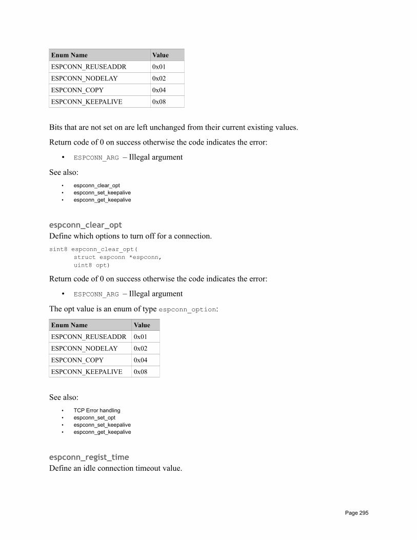
Enum Name Value
ESPCONN_REUSEADDR 0x01
ESPCONN_NODELAY 0x02
ESPCONN_COPY 0x04
ESPCONN_KEEPALIVE 0x08
Bits that are not set on are left unchanged from their current existing values.
Return code of 0 on success otherwise the code indicates the error:
• ESPCONN_ARG – Illegal argument
See also:
• espconn_clear_opt• espconn_set_keepalive• espconn_get_keepalive
espconn_clear_optDefine which options to turn off for a connection.
sint8 espconn_clear_opt(struct espconn *espconn,uint8 opt)
Return code of 0 on success otherwise the code indicates the error:
• ESPCONN_ARG – Illegal argument
The opt value is an enum of type espconn_option:
Enum Name Value
ESPCONN_REUSEADDR 0x01
ESPCONN_NODELAY 0x02
ESPCONN_COPY 0x04
ESPCONN_KEEPALIVE 0x08
See also:
• TCP Error handling• espconn_set_opt• espconn_set_keepalive• espconn_get_keepalive
espconn_regist_timeDefine an idle connection timeout value.
Page 295
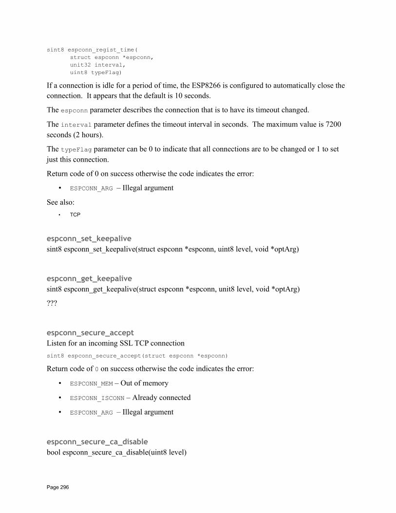
sint8 espconn_regist_time(struct espconn *espconn,unit32 interval,uint8 typeFlag)
If a connection is idle for a period of time, the ESP8266 is configured to automatically close the connection. It appears that the default is 10 seconds.
The espconn parameter describes the connection that is to have its timeout changed.
The interval parameter defines the timeout interval in seconds. The maximum value is 7200 seconds (2 hours).
The typeFlag parameter can be 0 to indicate that all connections are to be changed or 1 to set just this connection.
Return code of 0 on success otherwise the code indicates the error:
• ESPCONN_ARG – Illegal argument
See also:
• TCP
espconn_set_keepalivesint8 espconn_set_keepalive(struct espconn *espconn, uint8 level, void *optArg)
espconn_get_keepalivesint8 espconn_get_keepalive(struct espconn *espconn, unit8 level, void *optArg)
???
espconn_secure_acceptListen for an incoming SSL TCP connection
sint8 espconn_secure_accept(struct espconn *espconn)
Return code of 0 on success otherwise the code indicates the error:
• ESPCONN_MEM – Out of memory
• ESPCONN_ISCONN – Already connected
• ESPCONN_ARG – Illegal argument
espconn_secure_ca_disablebool espconn_secure_ca_disable(uint8 level)
Page 296
espconn_secure_ca_enablebool espconn_secure_ca_enable(uint8 level, uint16 flash_sector)
espconn_secure_set_size
espconn_secure_get_size
espconn_secure_connectForm an SSL connection to a partner.
sint8 espconn_secure_connect(struct espconn *espconn)
Form an SSL connection to a partner.
Return code of 0 on success otherwise the code indicates the error:
• ESPCONN_MEM – Out of memory
• ESPCONN_ISCONN – Already connected
• ESPCONN_ARG – Illegal argument
espconn_secure_sendSend data through a secure connection.
sint8 espconn_secure_send(struct espconn *espconn, uint8 *pBuf, uint16 length)
Send data through a secure connection.
espconn_secure_disconnectSecure TCP disconnection.
sint8 espconn_secure_disconnect(struct espconn *espconn)
Secure TCP disconnection.
Do not call this function from within an ESP callback function.
espconn_tcp_get_max_conReturn the maximum number of concurrent TCP connections.
uint8 espconn_tcp_get_max_con()
Page 297
espconn_tcp_set_max_conSet the maximum number of concurrent TCP connections
sint8 espconn_tcp_set_max_con(uint8 num)
espconn_tcp_get_max_con_allowGet the maximum number of TCP clients allowed to connect inbound.
espconn_tcp_set_max_con_allowSet the maximum number of TCP clients allowed to connect inbound.
espconn_recv_holdSuspend receiving TCP data.
sint8 espconn_recv_hold(struct espconn *espconn)
Suspend receiving new data over TCP. To resume receiving data, one can use the espconn_recv_unhold function call.
• espconn_recv_unhold
espconn_recv_unholdUnblock receiving TCP data.
sint8 espconn_recv_unhold(struct espconn *espconn)
Resume receiving new data over TCP. This method should be used in conjunction with espconn_recv_hold which suspends receipt of data.
See also:
• espconn_recv_hold
UDP APIs
espconn_createCreate a UDP control block in preparation for sending datagrams.
sint8 espconn_create(struct espconn *espconn)
Return code of 0 on success otherwise the code indicates the error:
• ESPCONN_ARG – Illegal argument
• ESPCONN_ISCONN – Already connected
• ESPCONN_MEM – Out of memory
Page 298
See also:
• UDP• espconn_regist_sentcb• espconn_regist_recvcb• espconn_send• espconn_delete• espconn_connect
espconn_igmp_joinJoin a multicast group.
espconn_igmp_leaveLeave a multicast group.
ping APIs
ping_startbool ping_start(struct ping_option *ping_opt)
Includes:
• ping.h
See also:
• Ping request• struct ping_option
ping_regist_recvbool ping_regist_recv(struct ping_option *ping_opt, ping_recv_function ping_recv)
Register a function that will be called when a ping is received. The signature of the function is:
void (*functionName)(void* pingOpt, void *pingResp)
The parameters passed in are pingOpt which is a pointer to the struct ping_option and pingResp which is a pointer to a struct ping_resp.
Includes:
• ping.h
See also:
• Ping request• struct ping_option• struct ping_resp
Page 299
ping_regist_sentbool ping_regist_sent(struct ping_option *ping_opt, ping_sent_function ping_sent)
Register a function that will be called when a ping is sent. The signature of the function is:
void (*functionName)(void* pingOpt, void *pingResp)
The parameters passed in are pingOpt which is a pointer to the struct ping_option and pingResp which is a pointer to a struct ping_resp.
Includes:
• ping.h
See also:
• Ping request• struct ping_option
mDNS APIsSee also:
• Multicast Domain Name Systems
espconn_mdns_initIntialize mDNS on the ESP8266.
void espconn_mdns_init(struct mdns_info *info)
The structure of type struct mdns_info contains vital initialization information and must be completed before calling this function.
See also:
• struct mdns_info
espconn_mdns_closeClose mDNS support.
void espconn_mdns_close()
Close mDNS support. This can be used following a call to espconn_mdns_init().
See also:
• espconn_mdns_init
espconn_mdns_server_registerRegister the mDNS server.
void espconn_mdns_server_register()
Page 300
espconn_mdns_server_unregisterUnregister the mDNS server.
void espconn_mdns_server_unregister()
espconn_mdns_get_servernameGet the mDNS server name.
char *espconn_mdns_get_servername()
espconn_mdns_set_servernameSet the mDNS server name.
char *espconn_mdns_set_servername()
espconn_mdns_set_hostnameSet the mDNS hostname.
void espconn_mdns_set_hostname(char *name)
espconn_mdns_get_hostnameGet the mDNS hostname
char *espconn_mdns_get_hostname()
espconn_mdns_disableDisable mDNS.
void espconn_mdns_disable()
See also:
• espconn_mdns_enable
espconn_mdns_enableEnable mDNS
void espconn_mdns_enable()
See also:
• espconn_mdns_disable
Page 301
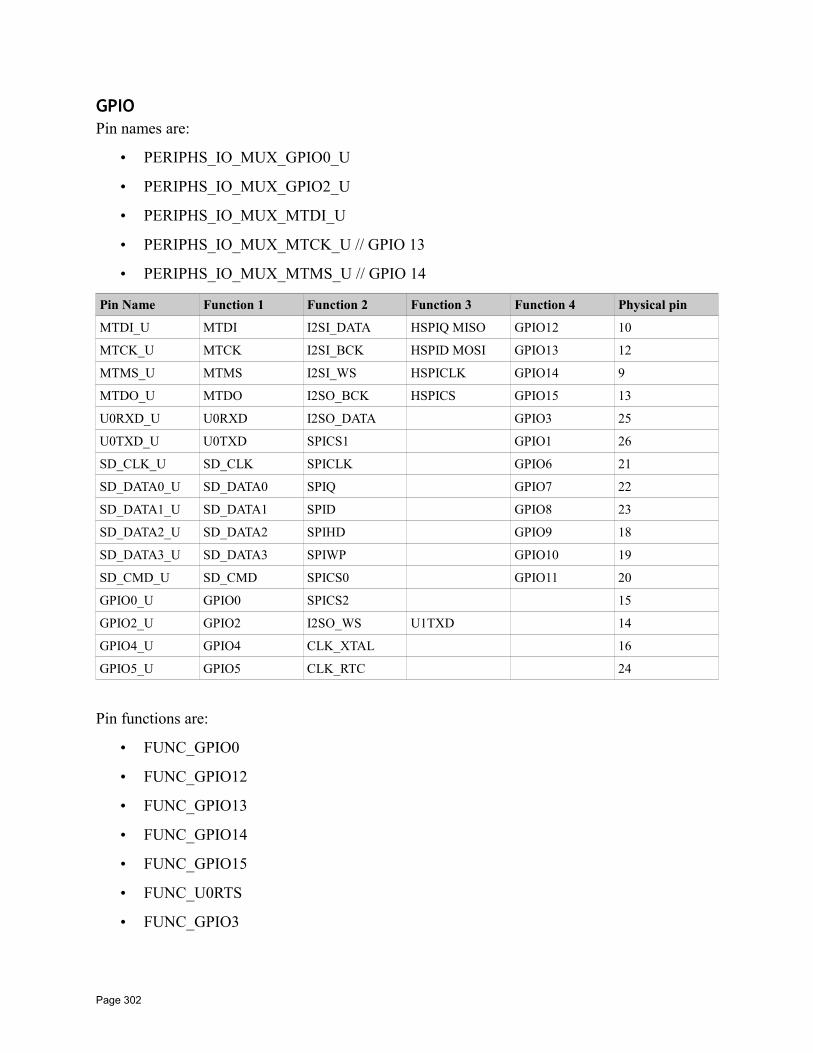
GPIOPin names are:
• PERIPHS_IO_MUX_GPIO0_U
• PERIPHS_IO_MUX_GPIO2_U
• PERIPHS_IO_MUX_MTDI_U
• PERIPHS_IO_MUX_MTCK_U // GPIO 13
• PERIPHS_IO_MUX_MTMS_U // GPIO 14
Pin Name Function 1 Function 2 Function 3 Function 4 Physical pin
MTDI_U MTDI I2SI_DATA HSPIQ MISO GPIO12 10
MTCK_U MTCK I2SI_BCK HSPID MOSI GPIO13 12
MTMS_U MTMS I2SI_WS HSPICLK GPIO14 9
MTDO_U MTDO I2SO_BCK HSPICS GPIO15 13
U0RXD_U U0RXD I2SO_DATA GPIO3 25
U0TXD_U U0TXD SPICS1 GPIO1 26
SD_CLK_U SD_CLK SPICLK GPIO6 21
SD_DATA0_U SD_DATA0 SPIQ GPIO7 22
SD_DATA1_U SD_DATA1 SPID GPIO8 23
SD_DATA2_U SD_DATA2 SPIHD GPIO9 18
SD_DATA3_U SD_DATA3 SPIWP GPIO10 19
SD_CMD_U SD_CMD SPICS0 GPIO11 20
GPIO0_U GPIO0 SPICS2 15
GPIO2_U GPIO2 I2SO_WS U1TXD 14
GPIO4_U GPIO4 CLK_XTAL 16
GPIO5_U GPIO5 CLK_RTC 24
Pin functions are:
• FUNC_GPIO0
• FUNC_GPIO12
• FUNC_GPIO13
• FUNC_GPIO14
• FUNC_GPIO15
• FUNC_U0RTS
• FUNC_GPIO3
Page 302
• FUNC_U0TXD
• FUNC_GPIO1
• FUNC_SDCLK
• FUNC_SPICLK
• FUNC_SDDATA0
• FUNC_SPIQ
• FUNC_U1TXD
• FUNC_SDDATA1
• FUNC_SPID
• FUNC_U1RXD
• FUNC_SDATA1_U1RXD
• FUNC_SDDATA2
• FUNC_SPIHD
• FUNC_GPIO9
• FUNC_SDDATA3
• FUNC_SPIWP
• FUNC_GPIO10
• FUNC_SDCMD
• FUNC_SPICS0
• FUNC_GPIO0
• FUNC_GPIO2
• FUNC_U1TXD_BK
• FUNC_U0TXD_BK
• FUNC_GPIO4
• FUNC_GPIO5
• LED_GPIO_FUNC
PIN_PULLUP_DISDisable pin pull-up
PIN_PULLUP_DIS(PIN_NAME)
Page 303

See also:
• GPIOs
PIN_PULLUP_ENEnable pin pull-up
PIN_PULLUP_EN(PIN_NAME)
See also:
• GPIOs
PIN_FUNC_SELECTSet the function of a specific pin.
PIN_FUNC_SELECT(PIN_NAME, FUNC)
See also:
• GPIOs
GPIO_ID_PINGet the id of a logical pin.
GPIO_ID_PIN(pinNum)
Convert a logical pin number into the identity of a pin. This is an interesting function as GPIO_ID_PIN(x) is coded to equal "x". The question now becomes whether or not one still needs to code GPIO_ID_PIN() when accessing GPIO functions.
GPIO_OUTPUT_SETSet the output value of a specific pin.
GPIO_OUTPUT_SET(GPIO_NUMBER, value)
This is a helper macro that invokes gpio_output_set(). Take care when passing in a value thatis part of an expression such as pData=='1'. The value is evaluated a number of times so shouldnot have side-effects. There is also a current bug related to operator precedence … it is strongly recommended to place the value in extra parenthesis when coding. For example:
GPIO_OUTPUT_SET(GPIO_NUMBER, (pData=='1'))
Includes:
• gpio.h
See also:
Page 304
• GPIOs
GPIO_DIS_OUTPUTSet the pin to be input (disabled output).
GPIO_DIS_OUTPUT(GPIO_NUMBER)
This is a helper macro that invokes gpio_output_set().
Includes:
• gpio.h
See also:
• GPIOs
GPIO_INPUT_GETRead the value of the pin.
GPIO_INPUT_GET(GPIO_NUMBER)
This is a helper macro that invokes gpio_input_get().
Includes:
• gpio.h
See also:
• gpio_input_get
gpio_output_setChange the values of GPIO pins in one operation.
void gpio_output_set(uint32 set_mask,unit32 clear_mask,uint32 enable_output,unit32 enable_input)
The parameters are:
• set_mask – Bits with a "1" are set high, bits with a "0" are left unchanged.
• clear_mask – Bits with a "1" are set low, bits with a "0" are left unchanged
• enable_output – Bits with a "1" are set to output
• enable_input – Bits with a "1" are set to input
Includes:
• gpio.h
Page 305
See also:
• GPIOs
gpio_input_getGet the values of the GPIOs.
unit32 gpio_input_get()
Retrieve the values from the GPIOs and return a bitmask of their values.
Includes:
• gpio.h
See also:
• GPIOs
gpio_intr_handler_registerRegister a callback function that will be invoked when a GPIO interrupt occurs.
void gpio_intr_handler_register(gpio_intr_handler_fn_t callbackFunction,void *arg)
The signature of the handler function must be:
void (*functionName)(uint32 interruptMask, void *arg)
Includes:
• gpio.h
See also:
• GPIO Interrupt handling
gpio_pin_intr_state_setvoid gpio_pin_intr_state_set(
uint32 pinId,GPIO_INT_TYPE intr_state)
The pinId is the GPIO pin id value returned from GPIO_ID_PIN(num).
The intr_state parameter defines what triggers the interrupt.
Includes:
• gpio.h
See also:
• GPIO Interrupt handling• GPIOs
Page 306
• GPIO_INT_TYPE
gpio_intr_pendingObtain the set of pending interrupts
uint32 gpio_intr_pending()
Includes:
• gpio.h
See also:
• GPIO Interrupt handling
gpio_intr_ackFlag a set of interrupts as having been handled. This should be called from an interrupt handler function.
void gpio_intr_ack(uint32 ack_mask)
Includes:
• gpio.h
gpio_pin_wakeup_enableDefine that the device can wakeup from light-sleep mode when an IO interrupt occurs.
void gpio_pin_wakeup_enable(uint32 pin,GPIO_INT_TYPE intr_state)
The pin parameter defines the pin number used to wake the device.
The intr_state defines which type of transition will wake the device. The choices are:
• GPIO_PIN_INTR_LOLEVEL
• GPIO_PIN_INTR_HILEVEL
Includes:
• gpio.h
See also:
• GPIOs• GPIO_INT_TYPE
gpio_pin_wakeup_disablevoid gpio_pin_wakeup_disable()
Page 307
Includes:
• gpio.h
UART APIsThese functions have to be compiled in from the uart files in driver_lib.
UART_CheckOutputFinishedbool UART_CheckOutputFinished(uint8 uart_no, uint32 time_out_us)
UART_ClearIntrStatusvoid UART_ClearIntrStatus(uint8 uart_no,uint32 clr_mask);
UART_ResetFifovoid UART_ResetFifo(uint8 uart_no);
UART_SetBaudrateSet the baud rate.
void UART_SetBaudrate(uint8 uart_no, uint32 baud_rate)
Set the baud rate used by the UART. The uart_no identifies the UART to set (0 or 1) and the baud_rate is the desired baud rate.
UART_SetFlowCtrlvoid UART_SetFlowCtrl(uint8 uart_no,UART_HwFlowCtrl flow_ctrl,uint8 rx_thresh)
UART_SetIntrEna
void UART_SetIntrEna(uint8 uart_no, uint32 ena_mask)
UART_SetLineInversevoid UART_SetLineInverse(uint8 uart_no, UART_LineLevelInverse inverse_mask)
UART_SetParitySet the parity.
void UART_SetParity(uint8 uart_no, UartParityMode parity_mode)
Set the parity used by the UART. The uart_no identifies the UART to set (0 or 1) and the parity_mode defines what to use.
Page 308
UART_SetPrintPortSet the output terminal.
void UART_SetPrintPort(uint8 uart_no)
Set the output terminal. Set the UART to be used when writing debug via os_printf().
UART_SetStopBitsSet how long the stop bits should be.
void UART_SetStopBits(uint8 uart_no, UartStopBitsNum bit_num)
Set how long the stop bits should be. The num identifies the number of stop bits to use.
UART_SetWordLengthSet the number of bits in a transmission unit.
void UART_SetWordLength(uint8 uart_no, UartBitsNum4Char len)
Set the number of bits in a transmission unit. The uart_no identifies the UART to set (0 or 1) and the len parameter defines how many bits.
UART_WaitTxFifoEmptyWait for the TX buffer to empty.
void UART_WaitTxFifoEmpty(uint8 uart_no, uint32 time_out_us)
Wait for the TX buffer to empty. The uart_no identifies the UART to set (0 or 1) and the time_out_us specifies how long to wait before giving up. The value is supplied in microseconds.
uart_initvoid uart_init(UartBautRate uart0BaudRate, UartBautRate uart1BaudRate)
There appears to be a typo in the data type … but likely we will be stuck with that now. The UartBautRate is an enum that contains:
• BIT_RATE_9600
• BIT_RATE_19200
• BIT_RATE_38400
• BIT_RATE_57600
Page 309
• BIT_RATE_74880
• BIT_RATE_115200
• BIT_RATE_230400
• BIT_RATE_460800
• BIT_RATE_921600
See also:
• Working with serial
uart0_tx_bufferTransmit a buffer of data via UART0.
void uart0_tx_buffer(uint8 *buffer, uint16 length)
Transmit the data pointed to by the buffer for the given length.
See also:
• Working with serial
uart0_sendStrTransmit a string of data via UART0.
void uart0_sendStr(const char *str)
Transmit a string of data via UART0. The string to send is supplied in the str parameter.
uart0_rx_intr_handlerHandle the receiving of data via UART0.
void uart0_rx_intr_handler(void *parameter)
The parameter is a pointer to a RcvMsgBuff structure. My best guess on how to use this functionis to create it in user_main.c and its mere existence will cause it to be invoked at the appropriate time. Looking at the sample supplied, we see that it needs a detailed low level implementation.
See also:
• Working with serial
I2C Master APIsThese functions have to be compiled in from the i2c_master files in driver_lib.
See also:
Page 310
• Working with I2C
i2c_master_checkAckRetrieve the ack from the data bus and return true or false.
bool i2c_master_checkAck()
Retrieve the ack from the data bus and return true or false.
i2c_master_getAckRetrieve the ack from the data bus and return its value.
uint8 i2c_master_getAck()
Retrieve the ack from the data bus and return its value. It isn't clear why this function might be exposed as well as the i2c_master_checkAck().
i2c_master_gpio_initConfigure the GPIOs and then call i2c_master_init().
void i2c_master_gpio_init()
Configure the GPIOs and then call i2c_master_init().
i2c_master_initInitialize I2C functions.
void i2c_master_init()
Initialize I2C functions.
i2c_master_readByteuint8 i2c_master_readByte()
i2c_master_send_ack
void i2c_master_send_ack()
i2c_master_send_nackvoid i2c_master_send_nack()
Page 311
i2c_master_setAckSet ack to i2c bus as level value.
void i2c_master_setAck(uint8 level)
Set ack to i2c bus as level value.
i2c_master_startSet I2C to send state.
void i2c_master_start()
Set I2C to send state.
i2c_master_stopSet I2C to stop sending state.
void i2c_master_stop()
Set I2C to stop sending state.
i2c_master_writeBytevoid i2c_master_writeByte(uint8 wrdata)
i2c_master_waitWait for a period of microseconds.
SPI APIsThese functions have to be compiled in from the SPI files in driver_lib.
cache_flush
spi_lcd_9bit_write
spi_mast_byte_write
spi_byte_write_espslave
Page 312
spi_slave_init
spi_slave_isr_handler
hspi_master_readwrite_repeat
spi_test_init
PWM APIs
pwm_initInitialize PWM.
void pwm_init(uint32 period,uint32 *duty,uint32 num_pwm_channels,uint32 (*pin_info_list)[3])
The period parameter is the PWM period. The value is measured in microseconds with a minimum value of 1000 giving a 1KHz period (there are 1000 periods of 1000 microseconds in asecond).
The duty parameter is the duty ration of each PWM channel.
The num_pwm_channels is the number of PWM channels being defined.
The pin_info_list is a pointer to an array of num_pwm_channels * 3 instances of unit32s thatprovides the PWM pin mappings.
See also:
• Pulse Width Modulation – PWM• pwm_set_duty• pwm_set_period• pwm_start
pwm_startvoid pwm_start()
After configuring the parameters for PMW, this function can be called.
See also:
• Pulse Width Modulation – PWM
Page 313
pwm_set_dutyvoid pwm_set_duty(uint32 duty, uint8 channel)
The resolution of a duty step is 45 nanoseconds. Here we can set the number of duty steps in a cycle. For example, imagine we have a period of 1KHz. This means that 1 cycle is 1000 microseconds. If we want the duty cycle to be 50%, then the output has to be high for 500 microseconds. 500 microseconds is 11111 units of 45 nanoseconds and that would become the duty value. Formulaic-ally, the duty ratio is (duty * 45) / (period *1000).
The duty parameter supplies the number of 45 nanosecond intervals that the output will be high in one period.
The channel parameter specifies which of the PWM channels is being changed.
See also:
• Pulse Width Modulation – PWM• pwm_get_duty• pwm_init
pwm_get_dutyuint32 pwm_get_duty(uint8 channel)
Get the duty value of the specified channel.
See also:
• Pulse Width Modulation – PWM• pwm_get_duty• pwm_init
pwm_set_periodSet the period for PWM operations.
void pwm_set_period(uint32 period)
The period parameter is the PWM period. The value is measured in microseconds with a minimum value of 1000 giving a 1KHz period (there are 1000 periods of 1000 microseconds in asecond).
See also:
• Pulse Width Modulation – PWM• pwm_get_period• pwm_init
pwm_get_perioduint32 pwm_get_period()
Get the current setting of the PWM period.
Page 314
See also:
• Pulse Width Modulation – PWM• pwm_set_period• pwm_init
get_pwm_versionuint32 get_pwm_version()
See also:
• Pulse Width Modulation – PWM
set_pwm_debug_en(uint8 print_en)Used to enable or disable debug print.
Bit twiddling• BIT(b) – The 2^b value
ESP Now
esp_now_add_peer
esp_now_deinit
esp_now_del_peer
esp_now_get_peer_key
esp_now_get_peer_role
esp_now_get_self_role
esp_now_init
esp_now_register_recv_cb
esp_now_register_send_cb
esp_now_sendThe maximum amount of data that can be sent as a unit is 256 bytes.
Page 315
esp_now_set_kok
esp_now_set_peer_role
esp_now_set_peer_key
esp_now_set_self_role
esp_now_unregister_recv_cb
esp_now_unregister_send_cb
Data structures
station_configA description of a station configuration. Contains the following fields:
• uint8 ssid[32] – The SSID of the access point.
• uint8 password[64] – The password to access the access point.
• uint8 bssid_set – Flag to indicate whether or not to use the bssid property. A value of 1 means to use and a value of 0 means to not use.
• uint8 bssid[6] – If several access points have the same SSID, BSSID can contain a MAC address to indicate which of the access points to connect to.
See also:
• Station configuration• wifi_station_get_config• wifi_station_get_config_default• wifi_station_set_config• wifi_station_set_config_current
struct softap_configConfiguration control structure for softAP.
• uint8 ssid[32]
• uint8 password[64]
• uint8 ssid_len – The length of the SSID. If 0, then the ssid is null terminated.
• uint8 channel – The channel to be used for communication. Values are 1 to 13.
• uint8 authmode – The authentication mode required. AUTH_WEP is not supported. The choices are:
AUTH_OPEN
Page 316
AUTH_WPA2_PSK
AUTH_WPA_PSK
AUTH_WPA_WPA2_PSK
AUTH_WEP is not supported.
• uint8 ssid_hidden – Whether or not this SSID is hidden. A value of 1 makes it hidden.
• uint8 max_connection – The maximum number of station connections. The maximumand default is 4.
• uint16 beacon_interval – The beacon interval in milliseconds. Values are 100 – 60000.
See also:
• wifi_softap_get_config• wifi_softap_get_config_default• wifi_softap_set_config• wifi_softap_set_config_current
struct station_infoThis structure provides information on the stations connected to an ESP8266 while it is an accesspoint. It is a linked list with properties:
• uint8 bssid[6] – The ???
• struct ipaddr ip – The IP address of the connected station
To get the next entry, we can use STAILQ_NEXT(pStationInfo, next).
See also:
• Being an access point• wifi_softap_get_station_info• wifi_softap_free_station_info
struct dhcps_leaseThis structure is used by the wifi_softap_dhcps_lease() function to define the start and end range of available IP addresses.
The fields contained within are:
• struct ip_addr start_ip
• struct ip_addr end_ip
Includes:
• user_interface.h
Page 317
See also:
• The DHCP server• wifi_softap_set_dhcps_lease
struct bss_infoThis structure contains:
• STAILQ_ENTRY(bss_info) next
• uint8 bssid[6]
• uint8 ssid[32]
• uint8 channel
• sint8 rssi – The received signal strength indication
• AUTH_MODE authmode
• uint8 is_hidden
• sint16 freq_offset
To get the next entry, we can use STAILQ_NEXT(pBssInfoVar, next).
The AUTH_MODE is an enum
• AUTH_OPEN – No authentication. No challenge on any station connect.
• AUTH_WEP = 1
• AUTH_WPA_PSK = 2
• AUTH_WPA2_PSK = 3
• AUTH_WPA_WPA2_PSK =4
See also:
• Scanning for access points
struct ip_infoThis structure defines information about an interface possessed by the ESP8266. It contains the following fields:
• struct ip_addr ip – The IP address of the interface.
• struct ip_addr netmask – The netmask used by the interface.
• struct ip_addr gw – The IP address of the gateway used by the interface.
See also:
• wifi_get_ip_info
Page 318
• wifi_set_ip_info• struct ip_addr• IP4_ADDR
struct rst_infoInformation about the current boot/restart
This structure contains:
• uint32 reason
• uint32 exccause
• uint32 epc1
• uint32 epc2
• uint32 epc3
• uint32 excvaddr
• uint32 depc
The reason field is an enum with the following values:
• 0 – Default restart – Normal start-up on power up
• 1 – Watch dog timer – Hardware watchdog reset
• 2 – Exception – An exception was detected
• 3 – Software watch dog timer – Software watchdog reset
• 4 – Soft restart
• 5 – Deep sleep wake up
See also:
• Exception handling• system_get_rst_info
struct espconnThis data structure is the representation of a connection between the ESP8266 and a partner. It contains the "control blocks" and identification information … however it is important to note that it is not always an opaque piece of data.
• enum espconn_type type – The type can be one of
ESPCONN_INVALID
ESPCONN_TCP – Identifies this connection as being of type TCP.
ESPCONN_UDP – Identifies this connection as being of type UDP.
Page 319

• enum espconn_state – The state can be one of
ESPCONN_NONE – The state for an in initial connection.
ESPCONN_WAIT
ESPCONN_LISTEN
ESPCONN_CONNECT
ESPCONN_WRITE
ESPCONN_READ
ESPCONN_CLOSE
• union esp_tcp *tcpesp_udp *udp
proto – This field is a union of tcp and udp meaning that only one of them should ever be used for an instance of this data structure. If the data structure is used for TCP then the tcp property should be used while for UDP, the udp property should be used.
• void *reverse – In the comments, this is flagged as a field reserved for user code. It is possible the name chosen (reverse) is actually a typo in the header file!!
• Other fields … there are other fields in the structure but they are not meant to be read or written to by user applications. Ignore them. Using their values is undefined and may have unexpected effects.
See also:
• TCP• esp_tcp• esp_udp
esp_tcp• uint8 local_ip[4] – The local IP address
• int local_port – The local port
• uint8 remote_ip[4] – The remote IP address
• int remote_port – The remote port
• Other fields … there are other fields in the structure but they are not meant to be read or written to by user applications. Ignore them. Using their values is undefined and may have unexpected effects.
See also:
• struct espconn
Page 320
esp_udpThis data structure is used in the proto property of the struct espconn control block.
• int remote_port – The local IP address
• int local_port – The local port
• uint8 local_ip[4] – The remote IP address
• uint8 remote_ip[4] – The remote port
See also:
• struct espconn• UDP
struct ip_addrA representation of an IP address.
It contains the following field:
• uint32 addr – The actual 4 byte IP address.
Includes:
• ip_addr.h
See also:
• ipaddr_addr• IP4_ADDR• ipaddr_t
ipaddr_tA typedef for struct ipaddr.
See also:
• struct ip_addr
struct ping_optionThe fields contained within the structure are:
• uint32 count – The number of times to transmit a ping
• uint32 ip – The IP address that is the target of the ping
• uint32 coarse_time
• recv_function recv_function
• sent_function sent_function
Page 321
• void *reverse;
Includes:
• ping.h
See also:
• Ping request• ping_start• ping_regist_recv• ping_regist_sent
struct ping_respThe fields contained within the structure are:
• uint32 total_count
• uint32 resp_time
• uint32 seqno
• uint32 timeout_count
• uint32 bytes
• uint32 total_bytes
• uint32 total_time
• sint8 ping_err – An indication of whether or not an error occurred. A value of 0 means no error.
Includes:
• ping.h
See also:
• Ping request• ping_start• ping_regist_recv• ping_regist_sent
struct mdns_info• char *host_name
• char *server_name
• uint16 server_port
• unsigned long ipAddr – This should be the IP address being offered.
• char *txt_data[10] – An array of options of the form "name = value".
Page 322
See also:
• Multicast Domain Name Systems
enum phy_modeThe 802.11 physical mode to be used or being used.
• PHY_MODE_11B
• PHY_MODE_11G
• PHY_MODE_11N
See also:
• wifi_set_phy_mode• wifi_get_phy_mode
GPIO_INT_TYPEThese are the possible triggers for an interrupt. This is an enum defined as follows:
• GPIO_PIN_INTR_DISABLE – Interrupts are disabled.
• GPIO_PIN_INTR_POSEDGE – Interrupt on a positive edge transition.
• GPIO_PIN_INTR_NEGEDGE – Interrupt on a negative edge transition.
• GPIO_PIN_INTR_ANYEDGE – Interrupt on any edge transition.
• GPIO_PIN_INTR_LOLEVEL – Interrupt when low.
• GPIO_PIN_INTR_HILEVEL – Interrupt when high.
See also:
• gpio_pin_wakeup_enable
System_Event_tThe event type contains:
• uint32 event – The type of event that occurred. Can be
EVENT_STAMODE_CONNECTED (0) – We have successfully connected to an access point.
uint8[32] event_info.connected.ssid – The SSID of the access point.
uint8 ssid_len
uint8[6] bssid
Page 323
event_info.connected.channel – The channel used to connect to the access point.
EVENT_STAMODE_DISCONNECTED (1)
uint8[6] event_info.disconnected.bssid
uint8[32] event_info.disconnected.ssid
uint8 ssid_len
uint8 event_info.disconnected.reason – The reason is one of the following:
• REASON_UNSPECIFIED = 1
• REASON_AUTH_EXPIRE = 2
• REASON_AUTH_LEAVE = 3
• REASON_ASSOC_EXPIRE = 4
• REASON_ASSOC_TOOMANY = 5
• REASON_NOT_AUTHED = 6
• REASON_NOT_ASSOCED = 7
• REASON_ASSOC_LEAVE = 8
• REASON_ASSOC_NOT_AUTHED = 9
• REASON_DISASSOC_PWRCAP_BAD = 10
• REASON_DISASSOC_SUPCHAN_BAD = 11
• REASON_IE_INVALID = 13
• REASON_MIC_FAILURE = 14
• REASON_4WAY_HANDSHAKE_TIMEOUT = 15
• REASON_GROUP_KEY_UPDATE_TIMEOUT = 16
• REASON_IE_IN_4WAY_DIFFERS = 17
• REASON_GROUP_CIPHER_INVALID = 18
• REASON_PAIRWISE_CIPHER_INVALID = 19
• REASON_AKMP_INVALID = 20
• REASON_UNSUPP_RSN_IE_VERSION = 21
• REASON_INVALID_RSN_IE_CAP = 22
• REASON_802_1X_AUTH_FAILED = 23
• REASON_CIPHER_SUITE_REJECTED = 24
Page 324
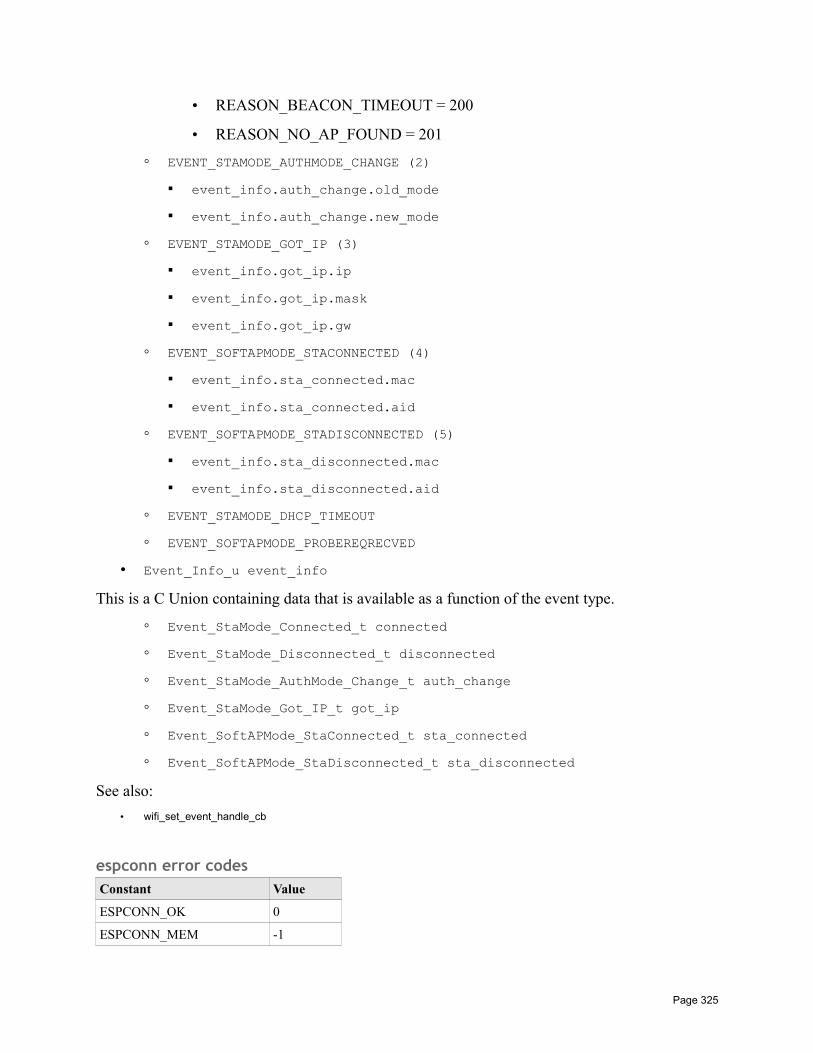
• REASON_BEACON_TIMEOUT = 200
• REASON_NO_AP_FOUND = 201
EVENT_STAMODE_AUTHMODE_CHANGE (2)
event_info.auth_change.old_mode
event_info.auth_change.new_mode
EVENT_STAMODE_GOT_IP (3)
event_info.got_ip.ip
event_info.got_ip.mask
event_info.got_ip.gw
EVENT_SOFTAPMODE_STACONNECTED (4)
event_info.sta_connected.mac
event_info.sta_connected.aid
EVENT_SOFTAPMODE_STADISCONNECTED (5)
event_info.sta_disconnected.mac
event_info.sta_disconnected.aid
EVENT_STAMODE_DHCP_TIMEOUT
EVENT_SOFTAPMODE_PROBEREQRECVED
• Event_Info_u event_info
This is a C Union containing data that is available as a function of the event type.
Event_StaMode_Connected_t connected
Event_StaMode_Disconnected_t disconnected
Event_StaMode_AuthMode_Change_t auth_change
Event_StaMode_Got_IP_t got_ip
Event_SoftAPMode_StaConnected_t sta_connected
Event_SoftAPMode_StaDisconnected_t sta_disconnected
See also:
• wifi_set_event_handle_cb
espconn error codesConstant Value
ESPCONN_OK 0
ESPCONN_MEM -1
Page 325

ESPCONN_TIMEOUT -3
ESPCONN_RTE -4
ESPCONN_INPROGRESS -5
ESPCONN_ABRT -8
ESPCONN_RST -9
ESPCONN_CLSD -10
ESPCONN_CONN -11
ESPCONN_ARG -12
ESPCONN_ISCONN -15
ESPCONN_HANDSHAKE -28
ESPCONN_PROTO_MSG -61
STATUSThis is an enum defined as follows:
Enum Name Value
OK 0
FAIL 1
PENDING 2
BUSY 3
CANCEL 4
See also:
• wifi_station_scan
Page 326
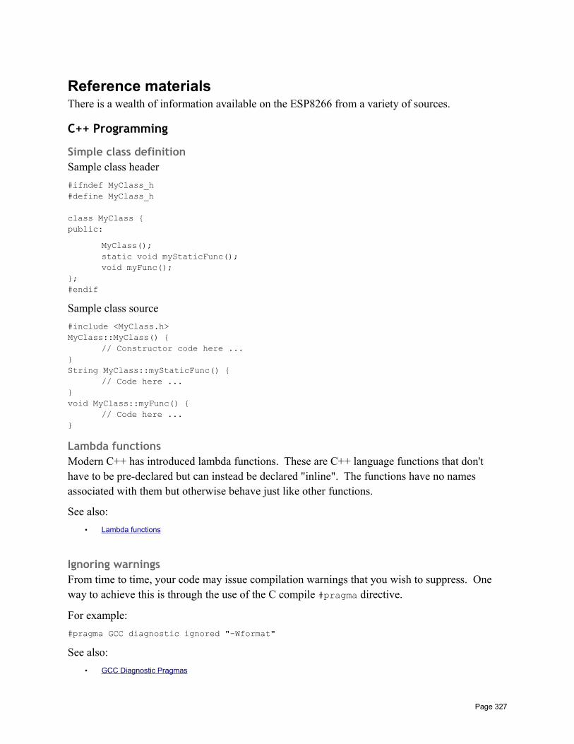
Reference materialsThere is a wealth of information available on the ESP8266 from a variety of sources.
C++ Programming
Simple class definitionSample class header
#ifndef MyClass_h#define MyClass_h
class MyClass public:
MyClass();static void myStaticFunc();void myFunc();
;#endif
Sample class source
#include <MyClass.h>MyClass::MyClass()
// Constructor code here ...String MyClass::myStaticFunc()
// Code here ...void MyClass::myFunc()
// Code here ...
Lambda functionsModern C++ has introduced lambda functions. These are C++ language functions that don't have to be pre-declared but can instead be declared "inline". The functions have no names associated with them but otherwise behave just like other functions.
See also:
• Lambda functions
Ignoring warningsFrom time to time, your code may issue compilation warnings that you wish to suppress. One way to achieve this is through the use of the C compile #pragma directive.
For example:
#pragma GCC diagnostic ignored "-Wformat"
See also:
• GCC Diagnostic Pragmas
Page 327
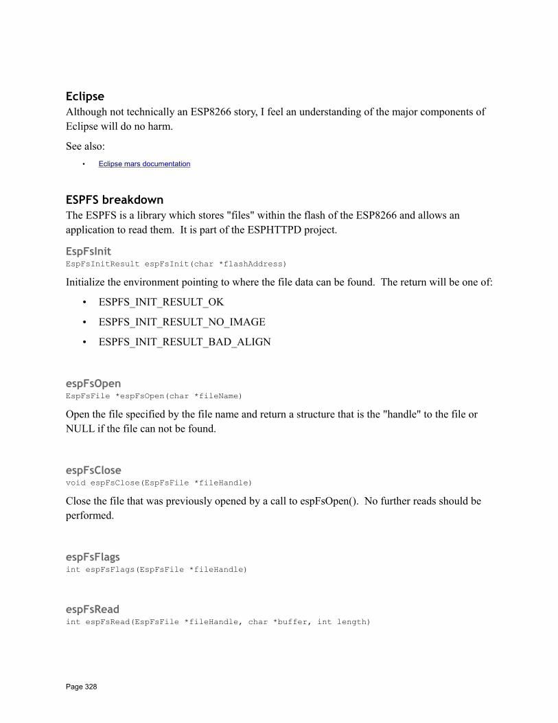
EclipseAlthough not technically an ESP8266 story, I feel an understanding of the major components of Eclipse will do no harm.
See also:
• Eclipse mars documentation
ESPFS breakdownThe ESPFS is a library which stores "files" within the flash of the ESP8266 and allows an application to read them. It is part of the ESPHTTPD project.
EspFsInitEspFsInitResult espFsInit(char *flashAddress)
Initialize the environment pointing to where the file data can be found. The return will be one of:
• ESPFS_INIT_RESULT_OK
• ESPFS_INIT_RESULT_NO_IMAGE
• ESPFS_INIT_RESULT_BAD_ALIGN
espFsOpenEspFsFile *espFsOpen(char *fileName)
Open the file specified by the file name and return a structure that is the "handle" to the file or NULL if the file can not be found.
espFsClosevoid espFsClose(EspFsFile *fileHandle)
Close the file that was previously opened by a call to espFsOpen(). No further reads should be performed.
espFsFlagsint espFsFlags(EspFsFile *fileHandle)
espFsReadint espFsRead(EspFsFile *fileHandle, char *buffer, int length)
Page 328
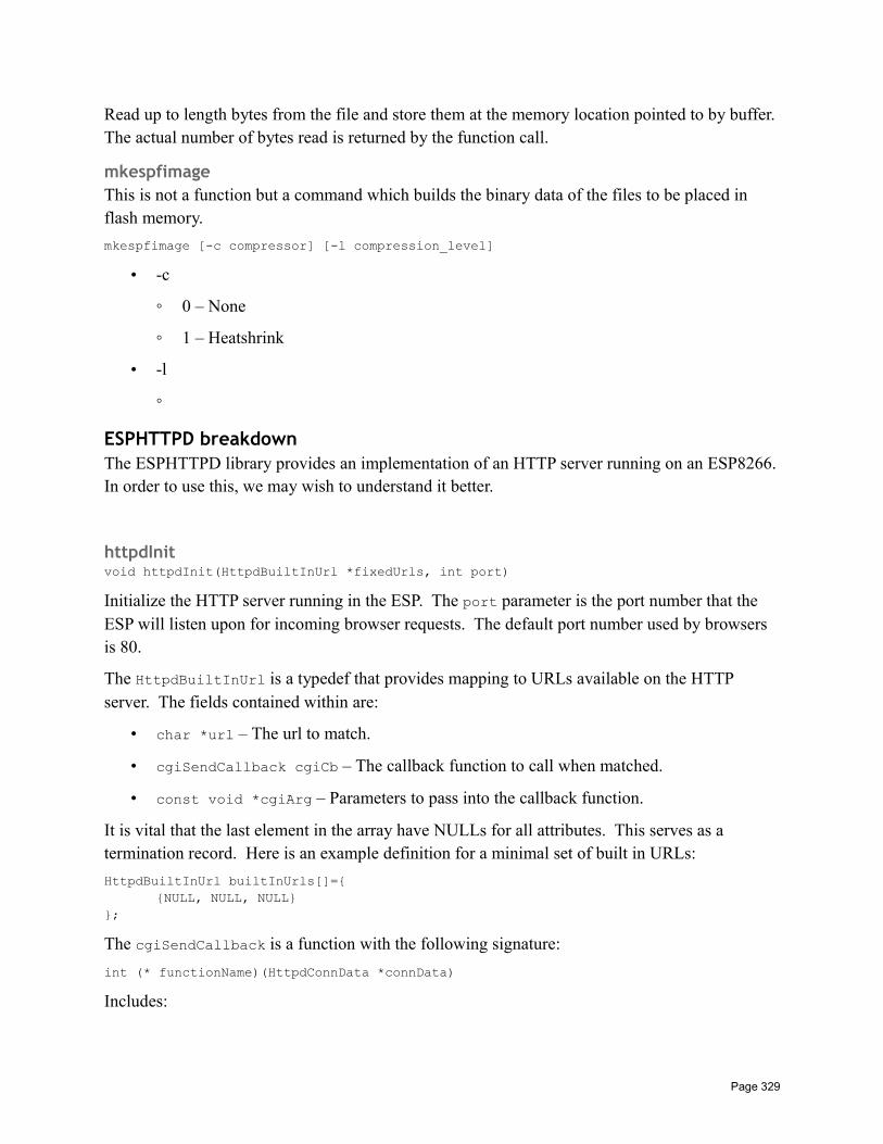
Read up to length bytes from the file and store them at the memory location pointed to by buffer. The actual number of bytes read is returned by the function call.
mkespfimageThis is not a function but a command which builds the binary data of the files to be placed in flash memory.
mkespfimage [-c compressor] [-l compression_level]
• -c
0 – None
1 – Heatshrink
• -l
ESPHTTPD breakdownThe ESPHTTPD library provides an implementation of an HTTP server running on an ESP8266.In order to use this, we may wish to understand it better.
httpdInitvoid httpdInit(HttpdBuiltInUrl *fixedUrls, int port)
Initialize the HTTP server running in the ESP. The port parameter is the port number that the ESP will listen upon for incoming browser requests. The default port number used by browsers is 80.
The HttpdBuiltInUrl is a typedef that provides mapping to URLs available on the HTTP server. The fields contained within are:
• char *url – The url to match.
• cgiSendCallback cgiCb – The callback function to call when matched.
• const void *cgiArg – Parameters to pass into the callback function.
It is vital that the last element in the array have NULLs for all attributes. This serves as a termination record. Here is an example definition for a minimal set of built in URLs:
HttpdBuiltInUrl builtInUrls[]=NULL, NULL, NULL
;
The cgiSendCallback is a function with the following signature:
int (* functionName)(HttpdConnData *connData)
Includes:
Page 329
• httpd.h
httpdGetMimetypechar *httpdGetMimeType(char *url)
Examine the url passed in and by looking at its file type, determine the MIME type of the data. If no file type is found, then the default MIME type is "text/html".
Includes:
• httpd.h
httpdUrlDecodeint httpdUrlDecode(char *val, int valLen, char *ret, int retLen)
Decode a URL according to URL decoding rules. The encoded url is supplied in val with a length of valLen bytes. The resulting decoded url string will be stored at ret with a maximum length of retLen. The actual length is returned by the function call itself.
Includes:
• httpd.h
httpdStartResponsevoid httpdStartResponse(HttpdConnData *conn, int code)
Start sending the response data down the TCP connection to the browser. The code value is the primary browser response code.
Includes:
• httpd.h
httpdSendint httpdSend(HttpdConnData *conn, const char *data, int len)
Send data to the browser through the TCP connection. The data is supplied as data and the len parameters is the number of bytes to write. If len == -1, then data is assumed to be a NULL terminated string.
Includes:
• httpd.h
Page 330
httpdRedirectvoid httpdRedirect(HttpdConnData *conn, char *newUrl)
Send an HTTP redirect instruction to the browser. The newUrl is the URL we wish the browser to use.
Includes:
• httpd.h
httpdHeadervoid httpdHeader(HttpdConnData *conn, const char *field, const char *val)
Send an HTTP header. The name of the header is supplied in the field parameter and its value supplied in the val parameter.
Includes:
• httpd.h
httpdGetHeaderint httpdGetHeader(HttpdConnData *conn, char *header, char *ret, int retLen)
Search the browser supplied data header looking for a header that matches the header parameter.If found, return the header value at the buffer pointed to by ret which must be at least retLen bytes long.
Includes:
• httpd.h
httpdFindArgint httpdFindArg(char *line, char *arg, char *buff, int buffLen)
Given a line of text, look for a parameter of the form "name=value" within the line. If the name matches our passed in name, then return the value.
Includes:
• httpd.h
httpdEndHeadersvoid httpdEndHeaders(HttpdConnData *conn)
Conclude the output of headers to the output stream.
Includes:
Page 331
• httpd.h
MakefilesBooks have been written on the language and use of Makefiles and our goal is not to attempt to rewrite those books. Rather, here is a cheaters guide to beginning to understand how to read them.
A general rule in a make file has the form:
target: prereqs …receipe ...
Variables are defined in the form:
name=value
We can use the value of a variable with either $(name) or $name.
Another form of definition is:
name:=value
Here, the value is locked to its value at the time of definition and will not be recursively expanded.
Some variables have well defined meanings:
Variable Meaning
CC C compiler command
AR Archiver command
LD Linker command
OBJCOPY Object copy command
OBJDUMP Object dump command
We can use the value of a previously defined variable in other variable definitions. For example:
XTENSA_TOOLS_ROOT ?= c:/Espressif/xtensa-lx106-elf/binCC := $(XTENSA_TOOLS_ROOT)/xtensa-lx106-elf-gcc
defines the C compiler as an absolute path based on the value of a previous variable.
Special expansions are:
• $@ - The name of the target
• $< - The first prereq
Comments are lines that start with an "#" character.
Wildcards are:
Page 332
• * - All characters
• ? - One character
• […] - A set of characters
Make can be invoked recursively using
make -C <directoryName>
Imagine we wanted to build a list of source files by naming directories and the list of source filesthen becomes all the ".c" files, in those directories? How can we achieve that?
SRC_DIR = dir1 dir2SRC := $(foreach sdir, $(SRC_DIR), $(wildcard $(sdir)/*.c))OBJ := $(patsubst %.c, $(BUILD_BASE)/%.o, $(SRC))
The puzzle
Imagine a directory structure with
aa1.ca2.c
bb1.cb2.c
goal is to compile these to
builda
a1.oa2.o
bb1.ob2.o
We know how to compile x.c → x.o
MODULES=a bBUILD_BASE=buildBUILD_DIRS=$(addprefix $(BUILD_BASE)/,$(MODULES))SRC=$(foreach dir, $(MODULES), $(wildcard $(dir)/*.c))# Replace all x.c with x.oOBJS=$(patsubst %.c,%.o,$(SRC))
all:echo $(OBJS)echo $(wildcard $(OBJS)/*.c)echo $(foreach dir, $(OBJS), $(wildcard $(dir)/*.c))echo "SRC: " $(SRC)
test: checkdirs $(OBJS)echo "Compiled " $(SRC)
.c.o:echo "Compiling $(basename $<)"
Page 333
$(CC) -c $< -o build/$(addsuffix .o, $(basename $<))
checkdirs: $(BUILD_DIRS)
$(BUILD_DIRS):mkdir -p $@
clean:rm -f $(BUILD_DIRS)
Makefiles also have interesting commands:
$(shell <shell command>) - Run a shell commands
$(info "text"), $(error "text"), $(warning "text") – Generate output from make
See also:
• GNU make• Makefile cheat sheet
ForumsThere are a couple of excellent places to ask questions, answer other folks questions and read about questions and answers of the past.
• Espressif ESP8266 BBS – A moderated forum run by Espressif. The primary source for SDK downloads and the source of much of the core materials.
• ESP8266 Community Forum – A set of fora dedicated to the ESP8266 run for and by the ESP8266 user community.
Reference documentsEspressif distributes PDF and Excel spreadsheets containing core information about the ESP8266. These can be downloaded freely from the web.
• 0A-ESP8266 - Datasheet v4.3• 0B-ESP8266 Hardware User Guide v1.1• 0C-ESP8266 WROOM WiFi Module Datasheet v0.3• 0D-ESP8266 Pin List Release 2014-11-15• 2A-ESP8266 IOT SDK User Manual V1.4• 2B-ESP8266 SDK IOT Demo V1.3• 2C-ESP8266 SDK Programming Guide V1.4• 4A-ESP8266 AT Instruction Set – Supplied with SDK• 4B-ESP8266 AT Command Examples – Supplied with SDK• 4C-ESP8266 AT upgrade example• 8A-ESP8266 Interface GPIO (Not yet published) v1.0• 8B-ESP8266 Interface GPIO Registers Release 2014-11-15• 8C-ESP8266 Interface I2C (Not yet published) v1.0• 8D-ESP8266 Interface PWM v1.1• 8E-ESP8266 Interface UART v0.2• 8F-ESP8266 Interface UART Registers v0.1• 8G-ESP8266 Interface Infrared Remote Control v0.3
Page 334
• 8H-ESP8266 Interface SDIO SPI M o o de v0.1-2 (Not yet published)• 8I-ESP8266 Interface SPI-WiFi Passthrough 1 – interrupt mode (Not yet published) v0.1• 8J-ESP8266 Interface SPI-WiFi Passthrough 2 – interrupt mode (Not yet published) v1.0• 8K-ESP8266 Sniffer Introduction v0.3• 8L-ESP8266 Interface SPI Registers Release 2014-11-18• 8M-ESP8266 Interface Timer Registers Release 2014-11-18• 8N-ESP8266 SPI Reference v1.0• 8O-ESP8266 SPI Overlap & Display Application Guide (Not yet published) v0.1• 8P-ESP8266 I2S Module Description v1.0• 8Q-ESP8266 HSPI Host Multi-device API v1.0• 9A-ESP8266 FRC Timer Introduction (not yet published)• 9B-ESP8266 Sleep Mode Function Description v1.0• 20A-ESP8266 RTOS SDK Programming Guide V1.0.3• 30A-ESP8266 Mesh User Guide V1.0• 99A-ESP8266 Flash RW Operation v0.2• 99B-ESP8266 Timer (not yet published)• 99C-ESP8266 OTA Upgrade v1.6
GithubThere are a number of open source projects built on top of and around the ESP8266 that can be found on Github. Here is a list of links to some of these projects that are very well worth having a look:
• EspressifApp• jantje/arduion-eclipse-plugin• eriksl/esp8266-universal-io-bridge• CHERTS/esp8266-devkit• ESPHTTPD project
Spritetm/esphttpd Spritetm/libesphttpd
SDKThe Software Development Kit (SDK) is published by Espressif and is required to build C based applications. It contains vital documentation in the form of PDF that don't appear to be availableelsewhere.
• ESP8266 SDK v1. 4 .0
esp-open-sdk
cygwin packages
bison
flex
texinfo
wget
patch
libtool
Page 335

automake
gettext-devl
Perform git clone --recursive <Repo> from within shell.
HeroesWithin the ESP8266 user community there are individuals that I consider to have pushed the boundaries of knowledge further or have developed tools that dramatically improve working with the devices. I want to take a few moments and call out these good folks without whom all our ESP8266 travels would be harder:
Max Filippov – jcmvbkbc – GCC compiler for XtensaWeb site: Github – https://github.com/jcmvbkbc
A compiler for C based on GCC that compiles to Xtensa binary for flashing. It is doubtful that any useful work could be performed without this contribution.
Ivan Grokhotkov – igrr – Arduino IDE for ESP8266 developmentWeb site: Github – esp8266/Arduino
An implementation of technology that allows one to develop ESP8266 applications using the Arduino IDE as well as libraries that map Arduino functions to ESP8266 equivalents or near equivalents.
Page 336

jantje – Arduino EclipseWeb site: Arduino EclipseWeb site: Github – jantje/arduino-eclipse-plugin
Although not technically for just the ESP8266, the Arduino Eclipse project is important. It provides the ability to build Arduino applications using Eclipse which has a superior development environment for more experienced programmers. Combine this with the Arduino ESP8266 project and we have a fantastic environment at our disposal.
Richard Sloan – ESP8266 Community ownerWeb site: http://www.esp8266.com/index.php
Without question, anyone who touches the ESP8266 should visit this community web site. The forum found there is extremely rich in knowledge and heavily trafficked. Folks new to the ESP8266 and experts alike are all welcomed. Simply come along, and join the fun. Richard is also the owner of the themindfactory.com.
Mikhail Grigorev – CHERTS – Eclipse for ESP8266 developmentWeb site: Project Unofficial Development Kit for Espressif ESP8266Web site: Github – CHERTS/esp8266-devkit
An extraordinarily well polished set of artifacts and instructions for building ESP8266 C applications within the Eclipse development environment.
Areas to Research• Hardware timers … when do they get called?
• If I define functions in a library called libcommon.a, what is added to the compiled application when I link with this library? Is it everything in the library or just the object files that are referenced?
Page 337

• What is the memory map/layout of the ESP8266?
• How much RAM is installed and available for use?
• Document the information contained here … http://bbs.espressif.com/viewtopic.php?p=3066#p3066
• What is SSDP and how does it related to the SSDP libraries?
• Study Device Hive - http://devicehive.com/
• What is SPIFFS?
• Document using Visual Micro debugger with Visual Studio. http://www.visualmicro.com/
• Study the Espruino JavaScript porting
• Power management
• MQTT support
• Research the semantics of a wifi_station_connect() when we are already connected.
Page 338