- the hera interaction region - the zeus detector - the quadrupoles
DESCRIPTION
- The HERA Interaction Region - The ZEUS Detector - The Quadrupoles. Superconducting Quadrupoles inside the HERA Experiments M. Bieler, DESY, LHC LUMI 05 Workshop, Arcidosso, September 2005. The HERA Interaction Region. 920 GeV Protons. 27.5 GeV Electrons. ZEUS Detektor. - PowerPoint PPT PresentationTRANSCRIPT

Superconducting Quadrupoles inside the HERA Experiments
M. Bieler, DESY,LHC LUMI 05 Workshop, Arcidosso, September 2005
- The HERA Interaction Region
- The ZEUS Detector- The Quadrupoles

The HERA Interaction Region
920 GeVProtons
27.5 GeVElectrons

ZEUS Detektor
p
e
Vorwärts-Kalorimeter
Rückwärts-Kalorimeter
Zentrales-Kalorimeter
Solenoid Magnet
Zentrale DriftkammerCTDMikrovertex-Detektor

GG

GO

As part of the HERA luminosity upgrade, 6 superconducting Interaction Region quadrupoles were delivered, accepted, and are in service. These 6 layer magnets were designed to include the main quadrupole focus, a skew quad, a normal and skew dipole, and a final sextupole layer.
Because of the physical space constraints imposed by the existing detector region components, the DESY magnets were of necessity designed to be very compact. In addition, they are also are required to operate within the solenoidal detector fields at the collision points, so all construction materials had to be non magnetic.
Two types of DESY magnets were fabricated. The first, designated as G0, was a two meter long, constant radius magnet. The second, designated GG, is a one meter long, tapered tube, with a continuously increasing field strength from the lead end towards the collision point.
From http://www.bnl.gov/magnets/HERA/default.asp
Design Parameters
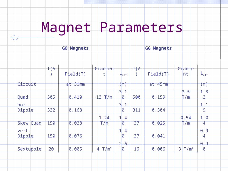
Magnet Parameters GO Magnets GG Magnets
I(A) Field(T) Gradient Leff I(A) Field(T) Gradient Leff
Circuit at 31mm (m) at 45mm (m)
Quad 505 0.410 13 T/m 3.10 500 0.159 3.5 T/m 1.33
hor. Dipole 332 0.168 3.10 311 0.304 1.19
Skew Quad 150 0.038 1.24 T/m 1.40 37 0.025 0.54 T/m 1.04
vert. Dipole 150 0.076 1.40 37 0.041 0.94
Sextupole 20 0.005 4 T/m2 2.60 16 0.006 3 T/m2 0.90

The GG Magnet

The GO Magnet
3.7m
17cm75cm

The GO Magnet

Cross Section of the GO Magnet
4K He Return40K He
40K He
3mm Beam Pipe5mm Coil Support Tube (102mm ID)
Coil Layers
3mm He containment (144mm OD)
Slotted G-10 SpacerStainless Support Key
60mm
90mm39mm
39mm for magnet and cryostat

Magnet Production at BNL- 11 axis wiring machine- 6 layers- Ultrasonic wire bonding- Pattern modulation to correct for field errors in lower layers- 5 circuits

Radial Magnet Design
Kapton Insulation
Coils in Substrat
S-Glas Kompression
LHe at 4KCa. 2mm
Quadrupole
Dipole
Sextupole
Skew Quad
Coil SupportTube (5 mm)
OuterHelium Tube (3 mm)
Coilsca. 11 mm
GO:

„6 around 1“ Cable
(ø .0 3 9 in [ .9 9 ] )
ø .0 1 3 in [ .3 3 0 ] B A R E W IR E
( .1 8 0 -.2 0 5 [4 .5 7 -5 .2 1 ] T AP E W ID T H )
.0 1 5 -.0 0 0
D O U B L E L A YE R C ap to n
+ .0 1 5.3 8 + .3 8
-.0 0[ ]
51 m
Filament: 8 m
Cu/NbTi: 1.8:1
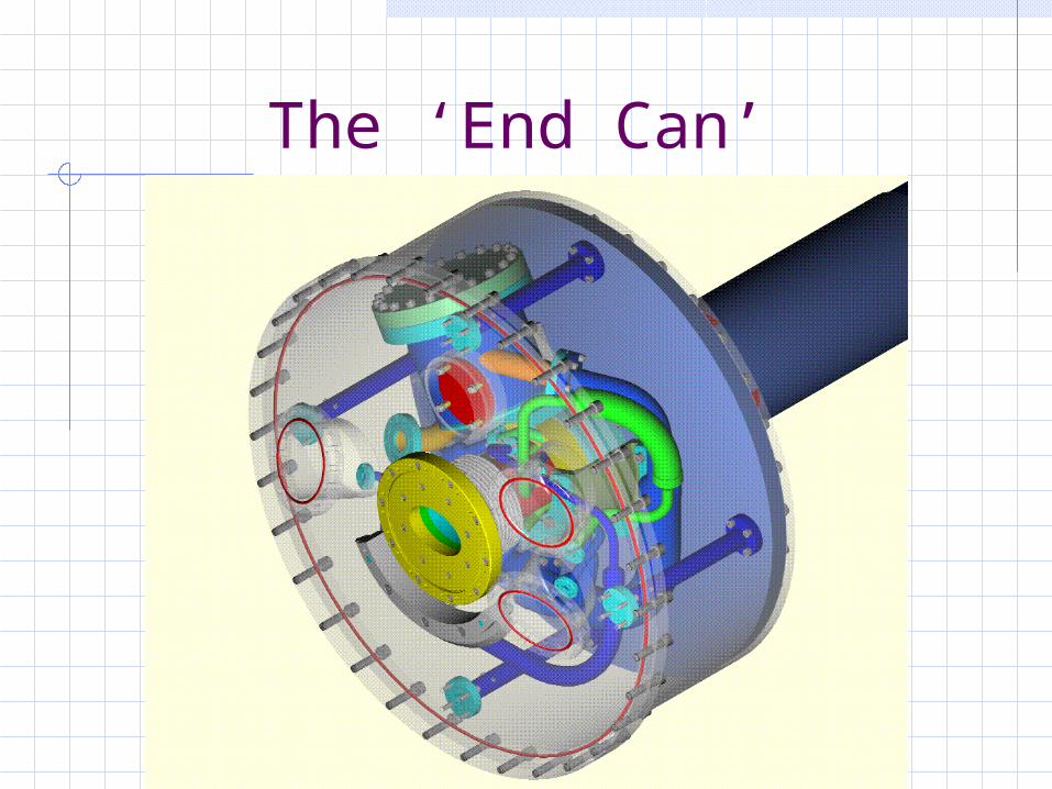
The ‘End Can’

Cryogenics
Heat load at 4K Heat load at 40K
Magnet (Watt) (Watt)
H1, GO 28 117
H1, GG 29 108
ZEUS, GO 50 104
ZEUS, GG 31 146
Measured static heat loads for the magnets and transfer lines(dynamic heat load: 6 – 15 W/m).
The magnet coils are cooled with supercritical single phase helium between 4K and 4.4K whereas the beam pipe iscooled between 40K and 80K.

Problems with GG and GOWater: The temperature of the outer magnet surface was so low, that water was condensing on the magnet, dripping down into the detector.Solution: Armaflex for thermal insulation, plastic bag to collect the water.
Magnet position: Inner tip of the magnet supported by steel cables or hydraulic movers.
Exact position of the tip can not be surveyed. Magnetic forces between the magnet and the experiment’s solenoid move the magnet by 1 mm during the energy ramp.
Solution: Electron orbit feedback system.
Cryogenics: Pressure drop in the magnets 3 times higher than expected.Solution: Additional circulation pumps.

References
Brück et al, Operational Experience with the newSuperconducting luminosity upgrade magnets at HERA,ICEC 19, Grenoble, France, 2002