, survey and alignment of the kloe experiment at da ne*
TRANSCRIPT
I a 35 Q V) ~ ~ ABORATORI NAZIONALI DI FRASCATI
l SIS - Pubblicazionishy)shy
I
lL LNF-97045 (P) ~ 10 Dicembre 1997 Z
-L~middotJ ~I
Survey and Alignment of the KLOE
Experiment at DAltIgtNE
A Ceccarelli S Dell Agnellot A Di Virgilio S Moccia Laboratori Nazionali di Frascati deUINFN Frascati (Rome) 1-00044
for the KLOE Collaboration
Abstract This review describes the survey and alignment program completed for the construction
-shyand the installation of the KLOE experiment from Februanr-~Jtrto-tct1Jtrert~r-----
I-----~___ -- ---+w--_--c
l---- -~--~ ~ ----~- I bull 1i __-- - - _- tmiddot-middot-~---
I --- -bull tPACS 4262Eh 0710+I 2940Gx 2940Vj
i -j
i
- -1I
i Presented at the
---- ~-~-~l j1h International Workshop on Accelerator _ ---- ---~
i ~ I 13-17 October 1997 Argonne National
~___ __ ~---- ---r-------
i I t _bull _------ -~ - ------~ ---__
DAltlgtNE the Double Annular ltlgt-factory for Nice Experiments is ~ spe+~Uil projects of the Isfiit~Nlionale di Fisica Nucleare (INFN) at LNF Italy KLOE the KLOng Experiment is a Gruppo I experiment of INFN
t Presented by S DellAgnello
-2shy
1 INTRODUCTION This review describes the survey and alignment work performed for the KLOE detector
designed and built by the KLOE collaboration [1] KLOE will operate at the DAltIgtNE ltIgt-factory e+e-~ltIgt~KLKs being commissioned at the Laboratori Nazionali di Frascati (LNF) The KLOE experiment described below is scheduled to start data taking in 1998 with the goal of studying a wide range of kaon physics topics including a precision measurement of CP
violation
Survey and alignment have been of crucial importance for the construction of KLOE Major projects completed by October 1997 are 1 assembly of the very large volume but extremely light-weight tracking drift chamber and
stringing of the 52140 wires alignment of the stringing robotics and monitoring of the deformations of the chamber carbon-fiber structure [2][3]
2 assembly of the iron return yoke for the 06 T superconducting solenoid (the worlds largest commercially-produced superconducting magnet) and alignment of the solenoid itself
3 measurement of the position of the magnetic axis with special care in the yoke pole regions where DAltIgtNE 500 MeV beams will be entering KLOE
4 field nlap of the magnet volume where DC and calorimeter photomultipliers will be located
Survey and alignment were carried out by means of a variety of hardware instrumentation software and techniques These include precision optical leveling infra-red polar measurement (theodolite with electronic distancemeter total stations) distance measurement with invar wires pulled by the DISTINVAR (a tool developed by CERN) close range videogrammetry by an external firm 3D contact measurenlents We acknowledge extensive use of the powerful block-adjustment software LGC (Logiciel General de Compensation) developed by CERN for processing survey data as well as the calibration of distance sensors in conjunction with our two total stations at the CERN geodetic interferometer base A significant fraction of the alignment work involved almost real-time surveys in which data were taken (with the CARNET program another CERN product) and processed on site with a portable PC without leaving the assembly hall before completion of the task Fast feedback portability and in consideration of the tight schedule and of the limited manpower available simplicity were the guiding principles in setting up a survey and alignment facility for KLOE The Leica TC2002 total station and distance measurements were the core of our work
This review is organized as follows KLOE is described in sec 2 survey tasks methods instrumentation and software are discussed in sec 3 while survey projects and results are presented in sec 4 to 8 for each KLOE sub-system
2 THE KLOE EXPERIMENT KLOE is a typical general-purpose collider detector with 41t coverage and cylindrical
geometry A relative low 06 T magnetic field over a very large volume 4 m diameter and 4 m
-3shy
length are a special requirement because of the low cm energy 102 GeV and the long decay path of long lived kaons 34 m in average The detector consists of a very large tracking drift chamber (DC) and a hermetic electromagnetic calorimeter (EmC) subdivided in various parts A pictorial view of the experiment is shown in Fig 1
Figure 1 cross section of KLOE showing (from inside to outside) spherical Be beam pipe quadrupoles carbon fiber drift chamber with spherical end plates barrel plus end cap electromagnetic calorimeters cryostat with superconducting coil and the iron return yoke which encloses everything On top are 4 flat iron platforms with engines for opening and closing the 4 yoke end cap halves
The low energy scale set by the value of the lttgt and K masses result in charged particle momenta 09 lt510 MeV Ic Photons from K decays have energies as low as 20 MeV K L decay vertices are uniformly distributed in radius and their decay products are isotropic distributed in azimuth may spiral in the DC and enter the EmC at unusual angles the projective geometry of typical collider events does not apply to KLOE Furthermore the large value of JBdl is a severe disturbance on the orbits of 500 MeV electrons This imposes very tight constraints on the alignment of KLOE magnetic axis especially in view of large luminosities 1033 cm-2 sec-I required by the experiment
With its point resolution of 200 Jlm in r-~ and 4 nun in z the DC is devoted to bull detection and decay-length measurement of Ks ~1t+1t- decays in the 10 cm radius ballshy
shaped Be beam pipe (Ks mean decay path at DAltIgtNE is 6 nun) bull detection of CP-violating KL ~1t+1t- uniformly spread in the DC volume (KL mean
decay path is 35 m)
I
-4shy
bull separation of KL ~1t+1t- from background KL ~ HJlV processes In addition in order to reduce Coulomb multiple scattering of charged particles K K s
regeneration and photon conversions the material in front of the calorimeter must be
minimized These requirements led to the choice of a cylindrical drift chamber with the following characteristics
bull diameter D=4 m and length L=33 m bull imnlersion in a 06 T magnetic field bull approximately uniform filling of the large tracking volume with 58 layers of all-stereo
drift-cells made of 119 (guard-sense-field) wire layers at constant radial displacement in the chamber midpoint (z=O)
bull 90 He gas mixture bull mechanical structure completely made of carbon-fiberepoxy with just 9 mm thick walls
but capable of sustaining the 4 ton load of the 53K wires with an axial displacement ~05 mm
The average material in front of the calorimeter is lt 01 Xo and its effect in term of KL regeneration is negligible The DC has an inner cylindrical hole of 25 cm radius to allow the presence of six DA(J)NE quadrupoles the Be beam pipe (ball-shaped at the center of KLOE to provide a vacuum chamber for Ks decays) and the so-called quadrupole calorimeters (see below)
The EmC must detect with very high efficiency extremely low energy photons from KKL ~1t01t0 measure their energies with a resolution oEE - 15 at 100 MeV provide the space coordinates of the photon conversion point in the EmCs with an accuracy of O(1) cm and
0 0reject K L ~ 1t 1t 1t0 background This is achieved with lead-scintillator sampling calorimeters
using 05 mm grooved lead layers and 1 mm diameter scintillating fibers yielding an excellent time resolution (55 psJE (GeVraquo and good energy resolution (47 JE (GeVraquo The chosen design provides a position resolution of 09 cmlJE (GeV) on the coordinate along the fibers (by
means of the time difference of the light measured at both ends) It also allows the construction of a truly hermetic calorimeter with no outer shell to contain calorimeter modules except an AI envelope of 01 mm thickness The calolimeter is read out with a granularity of about 4x4 cm2
bull
Therefore the position resolution on the coordinates normal to the fibers is also O( 1) cm
The EmC is divided into the following components bull The central calorimeter made out of 24 modules of trapezoidal cross section 43 m
long 23 cm thick approximating a cylindrical shell of 4 m inner diameter (fibers parallel to the detector axis) around the DC
bull Two end-cap calorimeters each consisting of 32 modules 23 cm thick with different lengths positioned vertically along the chords of the circle inscribed in the barrel which close the DC forward and backward (fibers normal to the axis)
bull Two calorimeters surrounding the low fJ insertion quadrupoles located inside the DC (QCALs) QCALs are needed to increase the coverage for KL ~1t01t01t0 rejection by detecting photons which would be absorbed by the quadrupoles and remain undetected
-5shy
by the other EmCs QCALs are sampling calorimeters made by lead and scintillator tiles
with wavelength-shifter fiber readout
For what concerns its physics goals KLOE is a precision real general-purpose experiment
In fact the choice of studying a pure quantum state with well-defined JPc=l- - quantum numbers the expected excellent performance of its detectors and the high design luminosity of the DAltlgtNE factory open up to KLOE a wide range of physics topics These span from the precision measurement of K-decay branching fractions to the investigation of CP violation
21 KLOE subsystems From the point of view of large physics installations atid related metrology aspects KLOE
is divided into four major subsystems (see Fig 2) the DC theEMCs the iron yoke and the
cryostat (44 m length 6 m diameter) containing the superconducting solenoid The iron yoke is
divided into 34 large pieces with a weight of 0(20) ton each The main body of the yoke has (very roughly) a cylindrical symmetry and hosts the cryostat This barrel yoke is also equipped with 4 wheels for movement along the rails and 4 engines to open and close the two end-cap parts of the yoke Barrel EmCs are assembled inside the cryostat (whose robust steel shell
supports their weight) end-cap EmCs are assembled directly on the yoke end-caps and the DC
will rest on the barrel EmC inner surface
Yet another SUbsystem which is under construction and will not be described here is the interaction region ofDAltlgtNE and KLOE A special structure will hold permanent quadrupoles
and QCALs inside the DC by distributing forces and torques on DC end plates and barrel EmCs The complexitymiddot of the interaction region is remarkable Alignment and assembly of
QCALs quadrupoles spherical Be beam pipe inside the DC in mid-1998 will be challenging
tasks
The two detector elements (EmC and DC) were built at LNF Two industrial firms
(SALVER from Brindisi and ReFraschini from Legnano) provided the DC mechanical
structure Success of the work done at external firms was due to close and constant help and collaboration by KLOE members which was a major maJ)power investment for several years The iron yoke was built by INNSE (now part of the Mannesman group) in Milan Oxford Instruments of England produced the solenoid and SKODA fabricated the cryostat outer shell as a subcontractor In this review we will report on the detector survey and alignment work at LNF and at external firms
The assembly of the yoke and solenoid in the KLOE experimental hall (completed in December 1996) started with delivery of iron yoke parts at the end of March 1997 From a survey point of view the installation proceeded with the following steps
bull installatipn of experiment rails (November 1996) bull pre-survey of iron yoke at INNSE as part of the acceptance tests (February 1997) bull creation of a network of permanent survey points (March 1997) bull assembly of the highly-segmented barrel yoke (April-May 1997)
-6shy
bull alignment of the solenoid inside the iron yoke (May 1997)
bull end-cap yoke alignment with respect to the solenoid (June 1997)
bull survey of cryostat inner surface for barrel EmC installation (June 1997) bull survey after first KLOE translation along rails (July 1997)
bull determination of KLOEs magnetic field axis (July-August 1997) bull survey and alignment of the CERN device for mapping KLOEs magnetic field in the
DC tracking volume and in the region of EmC photomultipliers (September-October
1997)
BARREL
Figure 2 one quarter cross sectional view of KLOE showing approximate dimension and location of the four subsystems
3 SURVEY AND ALIGNMENT
31 Tasks The required survey accuracy and alignment tolerance which provide the guidelines for the
strategy and instrumentation to adopt for KLOE vary with the subsystem
The position-sensing elements of the drift chamber are sense wires located in the drift cells For the KLOE DC we aim at a survey precision lt02 mm This is because survey positions
-7shy
have to be used as a starting point for a track fit algorithm which has the u1tim~te goal of measuring wire positions with an error 005 mm significantly smaller than the DC point resolution (02 mm) Sub-millimeter survey constants simplify and ensure the convergence of the fit whose final precision is mainly limited by track statistics On the contrary for the relative alignment of the two DC end plates with respect to the axis connecting their centers we can tolerate 1 mm misalignments In fact rigid-body misalignments of this magnitude between the two end plates induce only variations of the drift-cell stereo angles lt02
The position-sensing elements of the calorimeter are the 4x4 cm2 bundles of fibers read out by light guides and photomultipliers The coordinate of the photon impact normal to fibers is found by the energy-weighted average of the positions of the hit detector elements The required EmC alignment tolerance and survey accuracy is O(1 )mm which makes the survey job less demanding than for the DC For this detector the difficulty is related to
bull the large number of modules to install (24 in the barrel 64 in the end-caps) with respect to a common axis
bull the goal of building a truly hermetic calorimeter where each module not contained in any protective rigid case is as close as possible to the adjacent modules
The alignment of the iron yoke with respect to the solenoid is driven by the interaction of the experiment with DAlt1lNE beam optics Accelerator physicists require an alignment tolerance lmm in the transverse plane on a 6m length (related to KLOEs size) that is lt02 mrad This tight constraint is related to the topology of the optics around KLOE and for a detailed explanation the reader is directed to the DAltpNE proposal
32 Strategy Prior to 1996 survey and alignment resources adequate to tbe installation of an experiment
having the dimensions and complexity of a LEP detector (although with a smaller number of sub-elements) did not exist in the LNF Research Division In view of the construction of KLOE a team composed by one metrologist one physicist and one engineer was charged with the responsibility of organizing an appropriate facility At the time of the iron yoke survey a second metrologist joined the team
In addition to the tasks listed above practical constraints we had to face were I time limitations for the completion of the first task (namely the survey and alignment of
the 1 1 DC prototype and of the wire-stringing robotics) II ease-of-use and effectiveness of the facility to setup (in part driven by I) we wanted our
facility to be simple to operate up to the limit of a single person using the theodolite savingprocessing the data with a portable computer and yielding the results in field with the only help of a person placing targets like employees of external contractors or random physicists (which happened quite often)
III capability to perform surveys in very different conditions and locations like at external firms (where technical support and possible planning turned out to be limited) in the
-8shy
DC clean room at LNF (which is a relatively stable environment) and in the KLOE hall (which is not as stable and controllable)
IV choice of a block-adjustment software to process survey data (largely driven by I to 111)
We chose to setup a single basic survey unit made by a precision total station (the Leica TC2002) associated targets and a portable PC We also chose to measure angles and distances for (almost) every surveyed point in order to decrease when possible the number of
intersecting measurements from different theodolite positions In this scheme the complexity of survey tasks was to be solved by the adoption of powerful software (CERN LGC) capable of block-adjustment with only 1 measuring theodolite and by the redundancy of the measurements Instead there are commercially available programs which work with at least two instruments simultaneously pointing all targets The TC2002 + PC + LGC seemed to us the fastest and simplest facility to setup suited to KLOE needs and having the additional feature of portability
33 Instrumentation and calibration The TC2002 is a precision theodolite equipped with an infrared electronic distancemeter
(EDM) based on the Wild DI2002 This total station has coaxial optics for the measurement of angles and distances from the same point that is the telescope is adjusted at the factory to make the infrared distance-measuring beam coincident with the telescopes line-of-sight Thus the TC2002 is capable of polar measurements for radii larger than its shortest focusing distance which is about 16 m Alternatively the instrument can provide the same 3D information in a cartesian reference frame with one axis coincident either with the plumb-line or its standing
axis Extensive use of the TC2002 for KLOEs survey and alignment has shown that is a
precise stable and versatile instrument apt to our needs
Our preferred targets are 3D spherical target pairs of various diameters one for angle measurements and the other one containing a reflector for distance measurement We used
bull two pairs of 26 mm diameter targets mainly used for the DC end plates and robotics bull two pairs of 40 mm diameter targets mainly used for the yoke and the solenoid cryostat bull two pairs of 889 mm diameter Taylor-Hobson spheres which are mainly used on
permanent network points or anyway in conjunction with CERN-standard referenceshy
target sockets
Whenever we can drill holes or use sharp edges on the object of our survey we then build simple fixtures to place there 3D targets which can be oriented at will towards the TC2002 without displacement of their centers When manipulation andor machining of objects to survey is not possible we do extensive use of adhesive retro-reflective tape targets as in the case of EmCs and to a lesser extent for the cryostat and the yoke Tape targets with superimposed geometrical design can greatly ease manual observation (allowing both distance and angles to be
measured) and are best used when well-defined points are required but their actual position is not of major importance for example as fixed reference points or to define a free-form surface
-9shy
Although the TC2002 is built with an intrinsic angular accuracy of 000015 gon (--2Ilrad) in field we nonnally achieve an accuracy S00010 gon as indicated by LGC Since on average we do measurements in a 2-10 m range (and never exceed 20 m) the quoted angular error amounts to 01-02 rom position error The distance along the line-of-sight is measured with a similar uncertainty as shown by the calibration of TC2002 plus 3D reflectors at the CERN interferometer geodetic base and confinned by LGC Fig 3 shows the deviation of the distance measured by the TC2002 with our reference Taylor-Hobson reflector (used only for calibrations) with respect to the interferometer The slope of the data points (about -25 ppm) is due to the atmospheric correction (temperature pressure and humidity in order of decreasing importance) This correction was on purpose not applied to the data to show its magnitude The intercept of the data at DTC2002-700 m is the target constant with this instrument Fig 4 shows the comparison of the data of Fig 3 (diamonds labeled matin) with the same calibration in the range 16-35 m and with coarser steps (triangles labeled apres midi) repeated at a different time a systematic shift of 01 rom is apparent The accuracy of distance measurements with Leica retro-reflective tape is about a factor two worse than for 3D reflectors as shown by the calibration of tape targets with an interferometer in Fig 5 (these data are taken from a certificate that we bought from Leica) This calibration is perfonned with the tape suface nonnal to the line-of-sight when observing at a different angle (in any case not smaller than 60deg) it is necessary to average the distances taken in the two telescope positions in order to get the accuracy of Fig 5
Calibration distancemetre TC2002 Base Geodesique CERN 01 Octobre 1996 matin T=22degC P=716
o 2 4 6 8 10 12 14 16 18 20
-00003 r---~-------~--~----~--~----~--~----~--~----~
E -00004-uffi -00005 IshyZ is _00006 f------+-----+----~-____I__ltI~~~---_+_~---_t-----+__--__+-------1
bull bull CI bullg -0000 7 ~---+---+-----+---+----+---amp----=--+---+---------1 CI o lshye -0 0008 ------------j---------+----j-------+----f-------tshy
-00009 ~--~--------~--------------~--~----~--~----~
DTC2002 (m)
Figure 3 calibration of KLOEs TC2002 with 3D reflectors with CERNs interferometer
-10shy
Calibration distancemetre TC2002 - Base Geodesique CERN 01 Octobre 1996 matin + apres midiT=22deg C P=716
o 5 10 15 20 25 30 35 -00002 --------------T----r--------------T---------
-00004 +----lt~~-----+-_ _t__ImiddotMatin I___i--_+_-_
u [6 Apres midi I a w ~ -0 0006 ~---=-~~=A~=-----l------I---_+---~ o bull -000 08 +--------+-----+----I-W---+---~____1I-----_+__shy
N o o3 -0001 l-e
-00012 ~--~--~----~---~~---~~-----~-----~
DTC2002 (m)
Figure 4 comparison of different calibrations of KLOEs TC2002 with 3D targets
Leica certificate of TC2002 calibration with retro-reflective tape target
o 20 40 60 80 100 1
08 -E 06 E- 04 u a w 02 IshyZ
00
bull bull bullbull bull bull
bull
--
bull bull-02
N 0 0 -04 N 0 I- -06 0
-08
DTC2002 (m)
Figure 5 calibration of KLOE s TC2002 with retro-reflective targets bought from Leica
The calibrations of 3D targets occurred in October 1996 Since then we periodically check the cross calibration with respect the reference prism by placing all targets in a standard CERN socket (using appropriate extensions for diameters =f 889 mm) and nleasuring the distance with
-11shy
the TC2002 forcefully centered in another socket The absolute calibration is then obtained by measuring the distance between the CERN socket centers with the invarlDistinvar technique with an accuracy of about 005 mm After intensive use of the 26 mm targets for the DC we measured in this way a drift of their calibration constant of 04 mm and 06 mm Additional checks can be performed by comparing coordinates of CERN sockets measured by the TC2002 with those given by our CMM in its fiducial volume
Work with the fundamental TC2002 unit was complemented by other instruments and methods
bull For leveling with accuracy better than 005 mm we bought the Leica NA2 automatic level and a 092 m invar staff which we used extensively for the DC (see below) This level equipped with the Leica GPM3 parallel plate micrometer is capable of 002 mm reading
bull A-I mm accuracy total station the Nikon DTM-A20LG which was used at the beginning of our work for the alignment of the DC 1 1 prototype
bull The Nikon AS automatic 01 mm reading level (with its parallel plate micr0meter) bull Other electronic and manual theodolites all of quality nowhere near that of the TC2002 bull When we needed 3D surveys of accuracy better than 005 mm to check the DC end plate
drilling and measure DC reference holes we decided to rent the service of a private company after getting acquainted with the technique
bull For 001 mm accuracy the LNF CMM was used to survey objects fitting its 12x10xO6 m3 fiducial volume and to check target supportsextensions which allow viewing targets (especially 3D targets) in positions visible from fixed theodolite points Many of these essential accessory parts were made by our machine workshop
bull For special but important applications like surveying the deformations of the DC end plates under various types of loads lengthy contact measurements by means of dial gauge micrometers were needed [3] In fact for their large diameter (4m) they did not fit the volume of common workshop machifles or CMMs and this turned out to be the most practical way to measure deviations from nominal shape
34 Software Use of a block-adjustment software package to process survey data is a must in complex
positioning metrology projects like constructions of general-purpose physics experiments Upon official request to the CERN survey group by the KLOE and LNF management we were granted the use of a copy of the executable of (the Windows 31 version of) LGC a versatile package developed over the years at CERN Some important features of LGC are
bull error compensation and coordinate adjustment at global level bull gross-error detection for single measurements (which allows the user to throwaway or
re-survey suspect points) bull statistical information to assess the overall reliability of the survey and its real accuracy
(which is usually worse than the nominal instrument accuracy)
-12shy
bull simulation of survey results for the chosen input geometrical configuration of points to measure type number and accuracy of measurements
bull useful utilities for viewing output coordinates in different reference frames (CHABA) and fit the data to basic geometric figures like planes circles and straight lines (FIGMOY)
Our typical working sequence is to read out and save TC2002 measurements on the portable PC via the serial port with the CARNET program and then LGC-process the data on the PC itself before leaving the KLOE assembly hall However when block-adjustnlent is not of major importance and fast feedback is needed we do not use the PC and exploit instead the built-in calculation capabilities of the TC2002 to read directly on its displays the information of interest This may apply to
bull first positioning of an object (whose alignment is to be refined at a later stage) bull direct survey of its dimensions (by taking distances of pairs of its points) and its
inclination with respect to the vertical bull establishing an approximate cartesian network of points for later use
This can be done by exploiting directly the TC2002 local coordinate system or by means of the so-called coordinate-geometry (COGO) functions Some COGO functions allow a simple resection of the instrument with respect to a maximum of 6 reference points and further calculation of the position of other points in the reference frame of the resection points In any case this use of the TC2002 requires manual input of reflector constants and of the atmospheric correction while when working with the PC only target labels need to be ent~red as all constants and corrections are added by CARNET This free station feature (used for about 20
of the jobs) of the TC2002 proved very practical in the large physics installation of some of the 20 ton parts of the KLOE iron yoke (for a total of 34 pieces) Most often however results obtained with this method are checked with LGC
4 DRIFT CHAMBER
41 Mechanics The C-fiber mechanical structure consists of 2 middotspherical end plates (EPs) which close it
longitudinally 12 struts holding the EPs in place and 12 outer panels plus an inner tube of diameter d=05 m which seal the gas volume The inner tube is not a structural ~lement as it carries no load and it is left floating at wire-stringing time The outer panels also carry no load as they are mounted and glued to struts and to EPs after stringing However they provide addition torsional and bending rigidity which helps for a safe handling of the OC during transportation to the KLOE hall An open view of the DC is shown in Fig 6
To meet the requirements on its thickness and axial displacement each EP is made of bull a C-fiber spherical shell of R-10 m curvature radius and 9 mmthickness bull an outer flange OF which closes its outer diameter (note that a similar inner flange IF
closes its inner d=05 m diameter)
-13shy
bull a separate concentric C-fiber ring of slightly larger radius located around the OF and connected to it with 48 titanium screws with built-in strain gauges
EPs thus built show membrane behavior under our typical wire loads which implies small axial displacement compared to flat plates of the same thickness When the wire load causes a significant EP displacement screws are tightened this tensioning ring (TR) contracts and by elastic reaction applies to the OF by means of the screws an outward radial pull (proportional to the TR deformation) The choice of optimal frequency (every how many strung wires) and applied magnitude (read out from the 48+48 strain gauges) of EP tensioning relies on predictions of the IDEAS engineering program extensively checked with direct tests carried out on EPs before the DC assembly These extensive mechanical tests performed on all DC components before their assembly (surveys of their shape and size of accuracy of wire-hole drilling measurements of their displacement or deformation under load) as well as the TR working principle are described in detail in ref [3]
Figure 6 open view of the KLOE carbon-fiber structure drift chamber showing spherical end plates struts quadrupoles and spherical Be beam pipe
-14shy
42 EP reference targets Before massive drilling of wire holes special reference marks (RMs) were machined on
EPs and their position measured by means of a one-day videogrammetry (VG)middotsurvey These DC reference targets (the RMs) are precisely machined holes whose x-y position js known
within a resolution OVG=30Jlm RMs are then surveyed with the TC2002 or NA2 using our 26 mm diameter 3D target pairs mounted into them by means of suited supports RMs are divided into 2 classes
bull 12 holes of 6 mm diameter located on EP flanges for the DC survey and alignment six of which define the x axis while the other six defme the y axis For each axis two are located on the IF (IRMs) and four are located on the OF Among these four two are axial holes (ORMs) like the IRMs while the remaining two are radial holes (RRMs)
bull 54 holes of 5 mm diameter uniformly distributed on EP shells for the survey of EP deformations (see below) On each EP there is roughly one plate reference mark (PRM)middot every 50x50 cm2
bull
The VG survey was very important also to check accuracy of the drilling machine in its actual working conditions as RMs were drilled in the same configuration of the wire holes In fact on the basis of VG results adjustments of the drilling procedure were introduced to achieve an overall accuracy of drill hole positions ODR= 100Jlm in both x and y coordinates of the EP plane The VG survey output was a least-squares fit of the nominal positions of the four IRMs and four ORMs which establishes the local cartesian reference frame The
coordinates of RRMs and PRMs are then given with respect to this frame This follows the operational drilling procedure RRMs have been excluded from the fit because for one of the EPs they were drilled at a later stage after VG was performed
43 Automated wire stringing A description of the wire stringing facility and procedure can be found in ref [4] Here
we only remind that all operations are performed in a clean room by three robots remotely controlled by one Power Macintosh computer running Labview Fig 1 shows a top view of
bull the platform supporting the robots and the DC bull wire-carrying robot P and robots AB equipped with crimpingtensioning tools bull EPA and EPB mounted via IFs on a support Fe tube (EPB is on the engine side) bull the DC q-rotation engine located at the right end of the Fe tube bull KLOE cartesian x and z axes
The Fe tube is machined to have a precise coupling with IFs (by means of AI flanges and prismatic guides) such that its axis is coincident with the IF axis thus defining the KLOE z direction (with origin on this axis at half way between EPs) The y axis is taken along the opposite of the gravity acceleration IFs are free to move longitudinally when the wire load causes displacement of the shells with the relative IF-Fe tube sliding allowed by the prismatic guides The C-fiber inner tube not shown in the figure is outside the lower-diameter Fe tube
-15shy
and is pre-glued to one IF and free to slide inside the other one The C-fiber tube will then be sealed onto the IFs at the end of stringing Also not shown in the figure are the 12 struts which keep apart the Eps
The clean room operational since March 1996 works at 22degC and is class 1000 in the DC area and class 10000 elsewhere An electronic system measures the wire mechanical tension by applying an appropriate voltage to wires and exploiting their capacitive coupling with neighbor wires
P(enelope) side A(rianne) side B(erthe)
bullbull
bullbull bullbull bull bull Figure 7 top view of the supporting rig and the three robots for the automated wire stringing of the KLOE drift chamber
44 Survey and alignment results Survey of the DC assembled on this support structure involved the measurement of the
following quantities with the NA2 the TC2002 and LGC
-16- ~
bull deviations from planarity of the ORMs of each OF AEP
bull deviations from parallelism between each OF average plane and the respective IF
average plane ~p
bull the relative ltP rotation of the two EPs around the z axis ltPEP
bull relative rotations of the two EPs around the x and y axes 8XEP and 8yEP
bull relative shift of the two EPs in the x-y plane Sxy
bull relative z distance of middle points of IFs (this quantity is much less relevant than the
others and needs only to be surveyed when we stick the DC into the calorimeter)
We find AEPA = 04 mm plusmn 01 mm and AEPB = 01 mm plusmn 01 mm and ~p AEp
Moreover OF and IF of each EP are concentric in x-y within our position resolution
Alignment of the EPs around the z axis is achieved by finely rotating EPA with respect to
EPB by means of a removable metal tie-rod attached to its OF EPA is loosened on the tube
and on the struts while EPB is held fixed by the ltP engine which works with a feedback
encoder Then the longitudinal axis is set horizontal by acting on the support tube This
iterative mechanical action was driven by the following optical measurements the ltP alignment
is done by setting the EP x axis horizontal separately for each EP using the N A2 to level
targets located on the two x-axis ORMs Repeating the procedure with the y axis and
averaging statistically compensates having to measure two EPs IRMs are also measured as a
check but they do not provide a significant improvement of the measurement since their
distance is reduced by a factor 75 compared to ORMs Taking into account instrumental and
target accuracy 0(ltpEP)=0015 mrad We measure ltPEP=036 mrad which amounts to 07 mm
displacement in the x-y plane at the ORM radius
By using RRMs we find 8XEP = 015 mrad plusmn 015 mrad 8yEP = 031 mrad plusmn 015 mrad
and Sx= -18 mm plusmn 02 mm Sy = +11 mm plusmn 02 mm Note that relative EP rotations and
shifts are geometrically and mechanically related They are misalignments of negligible effect
on the robots because robots were aligned with respect to each EP separately Their effect on
the value of the wire stereo angles is discussed below
45 Stereo angles The nominal stereo angle E varies from plusmn63 mrad for innermost layers (radius of 275
nun) to plusmn148 mrad for outermost layers (radius 1937 mm) Note that the contribution of ODR
to the error on E is OE(DR) 0050 mrad In the following we consider separately the
implications of non-zero values of the largest angular rotation ltPEP and of the combined shift
SXY =~S~ +S~
The measured value of ltPEP produces a systematic variation of E which is uniform across
cells of a layer of about 022 mrad for the outermost layer (015 of its value) and of about
0035 mrad for the innermQst layer (006 of its value) The contribution of the survey accuracy on E is OE(SR) lt 0010 mrad for all layers
-17shy
A parallel rigid-body EP shift SXY =2 rom has a different effect depending on how the DC axis (defined as the line connecting EP centers) is installed with respect to the KLOE magnetic axis (which needs to the parallel to the bisetrix of DAltpNE beams in the center of KLOE) If
bull the DC is installed with one EP plane normal to the magnetic axis bull DC stereo angles are computed with respect to the magnetic axis ie considering EP
B as misassembled then the 2 rom shift would produce a variation of E non-uniform throughout cells of a same layer (some stereo angles increase and some other ditpinish) For example for innermost layers the variation goes from -11 to +11 (plusmn 07 mrad) which amounts to a systematic 22 relative non-uniformity of E within a layer which would add to the complication of cell-to-cell calibration of the DC Instead if the DC is installed with its axis as coincident as possible with the magnetic axis none of the EPs will be normal to the magnetic axis but they will be tilted by 24 rom (and still parallel) over the diameter of the outermost layer The systematic variation of E (with respect to the magnetic and DC axis) will be again non-uniform within a layer but much smaller in magnitude laquo02 systematic variation) Note that the contribution of the survey accuracy on E is Oe(SR) lt 0070 mrad for all layers
46 Wire stringing robotics The second part of the job was the survey of robot positions and the alignment of their
motion rails with the KLOE cartesian reference frame Several iterations were needed to mechanically adjust the rails of the wire crimping robots A and B to make them straight and orthogonal It was necessary to align the wire-carrying robot P with respect to the each EP separately since its 3m long rails showed deviation from straight-line motion at the order of 2 mm In addition the encoder of its y motion had to be calibrated (it showed before 2 mm errors) and the sizeable y-bending of its x arm when reaching inside the DC (10-20 mm depending on z) was carefully surveyed As a result of the work the robot hardware and software were improved
The robot survey was done with the NA2 the invar staff the Nikon total station and 3D
target pairs of 26 mm diameter mounted on the robots (in the place of the crimping jaws or of the wire needle support) by means of ad-hoc precisely machined fixtures This instrumentation was adequate for the required alignment tolerances
bull 05 mm for robot P whose main task is centering the 3 rom diameter holes with a 1 mm diameter needle
bull 02 mm in y (the automatic jaws close vertically) and 05-10 rom in x and z (the jaws are flat in x and the metal pin can be crimped equally well on 0(1) rom z position) for robot AlB
Survey and alignment in y was done using the level Triangulations done with the total station and 3D targets provided x and z information
-18shy
47 Measurement and Control of EP deformation A special task was the measurement of the z-displacement profile of each EP shell in
connection with the tensioning of the outer ring which occurs roughly every one month of wire stringing (about every 7000 strung wires) The measurement takes full advantage of the TC2002 and LGC It consists of the survey of EP deformations and of the relative distance of RRMs to check the null change of axial length of the struts EP deformations are given in terms of z-coordinate variations of IRMs and PRMs with respect to the ORM average plane The 26 mm diameter 3D targets were used for this work These surveys were important at the very beginning of the wire stringing to confirm that leaving IFs floating was the optimal choice (vs the option of constraining them in a fixed position) to avoid freezing the EPs in a nonshyequilibrium position In fact the survey showed that keeping the inner flanges fixed induced unwanted and dangerous deformations of the DC structure making difficult ultimately to control the wire mechanical tension and sagittae We corrected and smoothed this situation by means of the tensioning rings using the TC2002 to check the effectiveness of the tensioning process
The tensioning rings are very effective in adjusting EP z-displacement due to the load of the strung wires in such a way as to control wire sagittae Fig 8 shows that sagittae are of the order of 025 mm after about 45000 strung wires (7 tensionings) which is the optimal value for the safe electrostatic operation of our drift cells In addition the uniformity of the sagitta across all layers (except layers 1-11) makes unnecessary lengthy and difficult cell-to-cell calibrations Note that after the attempt to string with IFs held fixed (described above) layers 1-11 ended up with sagittae of about 07-08 mm To reduce this to a lower and safer value we progressively increased the tensioning magnitude For example the applied pull on EPs at th~ 7th (most
DRIFT CHAMBER WIRE SAGITTAE BEFORE AND AFTER 7TH EP TENSIONING
055
05-E
-E 045
~ 04 t-a 035 laquo U) 03 we 025 3
02
015
I
I
I 1tU
bull I I-AFTE rt RI
~ -- bull bull bull bull----- bull bull -
o 20 40 60 80
LAYER
bull
Figure 8 KLOE drift chamber wire sagittae calculated from the measurement of wire mechanical tension obtained independently of survey
-19shy
E 12
S 1
S 08 j ~ 06 c
04
_ 02 Q
g 0 an litj-02 enE -04
-06
Figure 9 adjustment of the distance of the KLOE drift chamber end plates by end plate tensioning in order to control wire sagittae Results are obtained independently from survey and are in agr~ement with TC2002 survey results
recent) tensioning was such that the z displacement recovery (difference afterlbefore tensioning) was on average 06 mmlEP as shown by Fig 9 and produced wire sagittae of Fig 8 Progressive EP tensioning is an essential ingredient for the successful construction of the KLOE drift chamber
Note that results in Fig 9 are obtained from the measurement of the wire mechanical tensions and are thus independent of survey However TC2002 measurements and wire mechanical tension results are in good agreement providing a positive check of the robustness of our redundant measurement system
5 CALORIMETERS The size and shape construction accuracy of each standalone calorimeter module is O(1) mm
level and they have been surveyed in detail with an accuracy better than 1 mm by means of contact measurements and the Nikon AS level The layout of calorimeters is shown in Fig 10
51 Barrel On each of the two ends of each barrel module two cross hairs have been engraved on
anodized aluminum plates The position of light guides which view the 4 cm x 4 cm sensing elements (and feed their light to photomultipliers) has been surveyed with respect to the cross hairs This has been done using a precisely machined plexiglass mask with a superimposed design showing the nominal positions of light guide centers with respect to the cross hairs Survey results are part of the EmC database Retro-reflective tape targets have then been positioned with their design coincident with the cross hairs to be measured by the TC2002 We
DIFFERENCE OF EP DISTANCE 45000 WIRES WITH DISTANCE 0 WIRES BEFORE AND AFrER TENSIONING
o 20 40 60 80 1
- -- -bull - bull bull~ - I I ItUHt I
-c---~- bull I bull bull LAYER
-20shy
estimate an overall survey accuracy of the relative position of light guides with respect to targets
better than 1 mm
SOO 1000 1500 2000 2500 3000
~ J
8MftEl IIOf TOIlE( 1~ coIl IJI tRlOSTAT
~ Tt nmElNlNL EIIC
l~ I ~~~ ORin
~ER DfDCAP
I~ [IIJCAP INC1
shy
I I I I I I I I
Figure 10 front (top figure) and side (bottom figure) view of the calorimeters showing their light guides and their position relative to other KLOE sub-systems Dimensions in mm
At the time of their installation into the cryostat (November-December 1997) barrel modules will be mounted trying to make their axis coincident with the measured magnetic axis (see below) and to reach a hermetic configuration by minimizing dead zones at lateral junctions of modules Tape targets will be surveyed with accuracy better than 05 mm by the TC2002 We aim at an alignment tolerance of a few mm but the actual alignment configuration will be
-21shy
driven by mechanical constraints like the regularity of the cryostat inner surface This was
surveyed in June 1997 to know how to shim the Erne modules
52 End cap End cap modules have been mounted before barrel modules in October 1997 Setting the
reference targets for the end caps was similar tlt the process followed for the barrel However in this case the position of the light guides is known with respect to retro-reflective tapes glued
directly on the Olmm AI skin of the front face of the calorimeters This was done by means of
contact measurements End caps modules are grouped into 4 halves (two for each side) and
they will be assembled onto corresponding halves of the iron yoke end caps by means of special
iron plates with their plane normal to the magnetic axis and their geometrical center lying on
that axis The mounting plates are mechanically designed to ensure the correct alignment of the
detector (with a tolerance similar to that of the barrel) and have the suited magnetic properties to
be part of the iron yoke poles In fact during the magnetic measurements prototype plates with
the same properties have been used to precisely simulate the final configuration
6 IRON RETURN YOKE AND SUPERCONDUCTION SOLENOID The yoke configuration is tyIical of collider experiments with a solenoid magnetic field The
-600 ton total weight of the yoke was divided into 34 pieces of an average weight of 20 tons
These pieces are (see Fig 11 and Fig 12) bull 8 upper and 4 lower semi-shells plus 2 long massive beams which connect upper and
lower semi-shells to form the barrel yoke (the barrel is divided longitudinally into 4 mega-ribs each made by a lower semi-shell an upper left semi-shell and an upper right
semi-shell)
bull 4 half end caps which form the yoke poles
bull end cap halves are pinned (two pinlhalf) with a 03 mm tolerance to 2 upper and 2 lower
semi-rings which interface the barrel with the end caps and allow a coarse relative
alignment of barrel and end caps at 1 mm level
bull 4 small semi-disks (1 for each half) which fill the central 07 m diameter hole of the end caps and are used for fine alignment of the poles with the main body of the yoke (and the solenoid once inserted) at 14 mm level
bull 4 platforms located on top of the barrel each equipped with an engine and a large bearing to translate and rotate end cap halves
bull 4 wheels located at the extremities of the two iron beams to move the experiment along the rails in the hall and roll it into the DAltIgtNE collision hall in 1998
-22shy
t-----3ec10-----t
Figure 11 side view of the KLOE iron return yoke showing one half end cap opened (left) and one closed (right) At the center of the opened end cap a semishydisk is visible with two square openings (on the right border of the semi-disk) to let out Erne cables as shown on the closed end cap Not shown in the figure is the central semi-circular hole of the semi-disk for the beam pipe The detailed shape of the semi-disks determines the exact configuration of the magnetic field at the poles The 4 mega-ribs of the barrel are also clearly visible Dimensions in mm
--------------------
-23shy
Ii
o ~r---------~laquo)--------~~
~ t-)
N
~~----------------------~----------------------~~ ()J
f
Figure 12 front view of the KLOE iron return yoke showing the locations of reference targets (marks) the end-cap engine platfonns and the wheels for rolling the experiment into the DAclgtNE collision haIl The correct semi-disk geometry is shown
~~~---~ shy
-24shy
The yoke was pre-surveyed at the end of construction at the INSSE finn with TC2002 + LGC in February 1997 This two-week measurement campaign was more a debugging of the yoke hardware and of the end cap opening procedure than a compreh~nsive survey of the entire ~oke Yoke reference targets (or marks YRMs) were 25 mm diameter bores machined on the
Iron at known positions Due to the shortage of the number of YMRs in the initial yoke project
we added 35 YRMs (by soldering pennanently on the iron 35 suited supports) and surveyed them with respect to machined YRMs Locations of YRMs on the various yoke parts are shown in Fig 12 Cylindrical magnetic supports of the screw-in type precisely machined were used to
center 3D targets of 40 mm diameter in the YRMs We measured and kept for future reference the barrel We checked the correct positions of the large holes in the end caps through which 6 engines push and pull the installation plates supporting the end cap EmCs We found a gross alignment error of 5 mm relative shift of the two end cap centers we found 16 mm and 30 mm gross errors in the positions of the machined holes on one of the end cap halves
Prior to yoke assembly at LNF two important jobs were carried out in the KLOE hall the installation of the experiment rails and the creation of a network of pennanent survey points which are described in appendix A
The complete assembly of the yoke occurred for the first time at LNF starting from March
1997 During the installation of the 2 iron beams with their wheels and the subsequent mounting of the barrel pieces we used the TC2002 as a free station for true online alignment
At the end with LGC we found that the 14 barrel pieces were assembled with an average deviation of 07 mm with respect to the YRM measurement at INSSE Note that barrel YRMs represent the yoke reference frame and axis Construction then proceeded with the installation of platforms with end cap enginessupports for the rest of April 1997 YRM positions surveyed
with the TC2002+LGC in the reference frame of the permanent network were related to the
local cartesian frame of the iron yoke by means of CHABA We estimate an accuracy in YRM coordinates ~ 02 mm When the system for moving KLOE was tested by shifting the yoke and
the cryostat back and forth by 15 m the survey showed variations of YRM coordinates in the yoke frame consistent with our resolution
In early May 1997 the 40 ton cryostat of the superconducting solenoid was inserted into the yoke and the nominal cold axis of the coil aligned with the yoke axis using the TC2002 as free station resected with respect to the YRMs This was done by means of ~ryostat r~feren~e marks (see below) knowing their expected offset with respect to ~e magneticcold aXIS ~his information was stated by the manufacturer (Oxford Instruments) In the followIng terms ~e
coil position when cold measured from the end-face datum marks of the vacuum case IS
expected to be 29 mm above datum 05 mm off vertical centre line away from the pover
supply unit on the service turret side (STS) and 09 ~ above d~tum 05 ~ off vertical centre line towards the power supply unit on the non service turret Side (NSTS) Cryo da~ marks are 4 engravings (ECRMs) of about 1 mm thickness x 1 mm depth located at nght angles on the two end faces of the cryostat (4 EC~sface) -pproximately cent~red on each EeRM there was also a threaded hole (which we Will refer to Simply as CRM) which we u~ed
5
-25shy
40 rom diameter 3D target pairs (4 CRMsface) LGC showed a
~~nmu~itilt of about 2 nun with respect to the yoke axis (corresponding to - 0
mrad over the cryostat length of 4 4m) s on the barrel axis with a tolerance
The following steps were the ~ig~ent of the ~nu-nng the semi-rings After considerable of 1 mm and the installation and pInmng of the en caps on the closed positions
d 0 ening and closing procedure therr centers In optImIZation of the en cap p b al d th the yoke axis within 1
d bl t rom level and to eIgne WI were measured to repr~n~c~~ mi alignment of the cryostat placed the coil axis parallel to
rom on aveage e sec (0 2 EB 0 2 mm4 4m _ 01 mrad) both in the horizontal (x) the yoke axIS WIthin our accuracy - 1 2 mm and in the vertical (y) direction although with the offsets (y) =05 nun and (x) -
The two end cap planes were normal to the yoke axis wIth a sImIlar accuracy
d k h with 3 YRMs were mounted and their centers finely Finally the 4 semI- IS s eac 0 hi th
adjusted to coincide with the nominal axis of the co~ and to ~e My) =(x) = Wit n e
resolution quoted above thus completing the installation and alIgnment of the system
7 DIRECT MEASUREMENT OF THE POSITION THE MAGNETIC FIELD
AXIS Knowledge and control of KLOEs magnetic axis is important given the tig~~ alignment
constraints imposed by the characteristics of DAqNEs optics The true pOSItion of the magnetic axis was measured by KLOE in August 1997 by means of a dedicated device built by
the accelerator division This measurement is a good check of the effectiveness of the
alignment similarly to the plot of the DC wire sagittae of Fig 8
This simple but effective machine measures the longitudinal field component and its r z and
lt1gt gradients This is done by means of a single Hall probe for 0 rnmS radii s 170 rnm (the semi-disk circular hole has a 200 rnm radius) and for a length Izl lt 35 m (about 14 m outside
each semi-disk external face) Since all B field components are strongly coupled by Maxwell equations the symmetry properties of Bz provides all information necessary to infer directly the
position in space of the magnetic axis along the whole length of KLOE In addition once the
axis location in space has been found it easily provides the field integral for 7 m along that axis which is necessary to DAqNEs physicists The information provided by the well-known CERN machine described in section 7 although three dimensional is geometrically less accurate which is a disadvantage for studying the field shape where field gradients are large like around the poles Moreover such machine only measures radii ~ 145 mm and Izi lt 19
Therefore it not only does not access to outer regions where knowledge of the field is of some importance for accelerator operation it does not measure the field at small radius and just in front and through the pole piece face The radial component becomes here very large and small misalignments severely deteriorate the optics of the new low ~ insertion Maxwell equations could allow determining the axis also with the data of the CERN mapper but in a less direct and
accurate way In practice they are of no help in the extreme case of DAltIgtNE and KLOE Given
r
-26shy
~he relean~e o~ the magnetic field axis information for the first collider factory to co nll m the nmet~es It was felt that a direct measurement was better suited Note that as remro ref [6] this measurement has never been performed by a al PKLOE gener -purpose expenment before
We refer to this device as MagAx (Magnetic Axis measurement device) and we describe bull re~ults of the standal~ne survey perfonned to assess ils intrinsic g~metrical properti~s bull alIgnment and operatton of the MagAx in lLOE
71 Standalone survey The MagAx main body is a precisely machined beam of about 7 m length made of a special
Al ~loy The 5~X14mm flat encasing of the Hall probe is precisely positioned normally to the 10ngIt~~Inal axI~ on the l~ng front face of a lcmxlcmx170 mm finger support The probe can be PO~Itto~ed WIth a fixatton screw at radii from 0 to 170 mm The finger can be moved along th axts alIgned along the nominal coil axis by means of a carriage and the beam can be rotated azImuthally All movements are performed manually Conceptual designs with front and side views of the MagAx are shown in Fig 13 and 14 to explain its working and alignment concept
Fig 13 shows the hall probe on its support which rests on the movable carriage which slides along an I-shaped beam The large outer flange is fixed with screws onto the semi-disks of the KLOE yoke poles while the inner flange supports the beam in its rotation about the longitudinal axis On the rotating flange there are reference marks (6 mm holes) in which 3D targets of 26 mm diameter can be mounted An intermediate alignment flange (not shown in the figure) which slides (thanks to special grease) in contact with the rotating flange allows fine alignment of the beam in the transverse plane This is done by acting with 6 screws on the alignment flange and displacing it with respect to the fixed flange and therefore with respect to
the yoke semi-disks
The MagAx was surveyed prior to its installation in KLOE by placing it on a long marble
platfonn tightly constrained to simulate its final configuration By pointing with the TC2002 a retro-reflective tape stuck on the probe protective case in order to measure 3D points we perfonned rotations and longitudinal scans of the 7 m length Points When needed we pointed directly the marks printed on the probe encasing indicating the position of the sensitive area We
measured the following propertiesbull the beam sagitta is about 114 mm over 7 m in accordance with expectations bull the beam is planar within 14 mm (which is basically due to its sagitta) and its plane is
normal to the rotating flanges (where MagAx reference marks MRMs are located)
within our measurement resolution bull the two rotation centers of the rotating flanges are found by fitting circles through 6
positions traCked by MRMs (every 60deg) in the same way by using the target on the probe we determined the centers of 7 additional circles located at the two zs o~ ~e rotating flanges at three equidistant zs in between and at the two MagAx extrenunes The fit of all circles in 3D is extremely good with typical radial deviations lt 01 mm
-27shy
and out-of-plane deviations of lt03 mm The straight line fit through these 9 centers is
good and basically shows only the 14 mm vertical deviation due to the beam sagitta bull the plane described by the probe marks when the probe is translated in r and z is offset
from the rotation axis by 03 mm
bull when moved along r the probe stays normal to the longitudinal rotation axis within the survey accuracy
These results guarantee that the MagAx is a rigidly moving object geometrically accurate at the 114 mm level adequate to satisfy its task
Fixed flange
Rotating flange
mark
Figure 13 front view of DAltIlNEs MagAx
-28shy
~----------------6000--------________~
~~~----------4200----------~
1 l
252
Ha probesupporting carriage
Figure 14 side vie~ of DAltf)NEs MagAx showing the pulley for longitudinal translation the rotation ann (two of them one for each side are used in reality) and the overall approximate dimensions (total length available for measurements is actually 7 m)
72 Alignment and operation in KLOE Alignment of the MagAx in KLOE was achieved by positioning the fixation flange with 3
mm tolerance on the semi-disks rotating the beam to find the x-y coordinates of the rotation I
center of MRMs and then finely adjusting the position of this center by displacing the intermediate flange (see Fig 13) The MagAx was aligned with the coiVsemi-disks axis within 02mm
The magnetic measurement procedure was very simple and gave online the information of the magnetic axis position We measured Bz at r =0 75 and 164 mm scanning ltIgt every 45deg (90deg) and z every 50 (100) mm in the yoke poles (center) The radius of the probe with respect to its rotation center in the outermost position which was precisely reproducible was measured with TC2002+LGC The relative radial displacement in any other position was found simply
-
-29shy
but precisely with a ruler Although the measurement is not very sensitive to ltp this angle was determined with few mrad accuracy by collimating two adjacent holes one fixed and the other one on a marked disk rotating with the beam Finally by means of the TC2002 as a free station (approximately aligned with the yoke axis) pointing the retro-reflective target on the probe we surveyed for each measured point the z coordinate which was th~ only missing information Knowledge of the KLOE z for all points was necessary in regions of high gradients (up to 16 Gmm) and to connect scans at different radii and at the same angle since the pulley was not equipped with an encoder In fact the z position of the probe can vary due to
bull thermal dilatation of the 7 mAl beam (there is no thermal conditioning in the hall) bull non-trivial manual operation of the device in KLOE (which was more difficult than for
the standalone survey)
bull pulling of the probe readout cable
The field value from the probe was read out via GPIB with a Macintosh computer running Labview while ltp and z were entered manually into Labview Inspection of the z and ltIgt
symmetry properties of the gradients of the longitudinal field component B revealed that the z measured magnetic axis was coincident with its expected position within experimental resolution The following figures report preliminary results showing the quality of the alignment
Figure 15 KLOE s solenoid longitudinal field c (z cm) measured by the MagAx compared with th~M1~eNntU(sBMz Gauss) along magnetic axis
onte Carlo program
6000
5000
4000
3000
2000
1000
o o
O bullbull 0900middotee~~~ deg0 tP
o
1 o
o R-
o
300 350 8z on axis
o Data
Simulation
------------------~-----30shy
Fig 15 shows Bz vs z in the data and in the Monte C sImulation curve are due to its cutoff at =300 fj ar~o Note that larger gradients In the
Z position of the yoke pole (inner and 0 t f cm rom coil center Vertical lines indicate the
u er aces 0 f the semi-d k) Th KL covers the region fzl lt 150 cm IS s e OE drift chamber
200
150 0 o degrees ~ 100 90 degrees
Data e
50 8
0 988 0
-50 II)
-100 0
-150 ~
-200 0
250 300
200
150
100
50
0
-50
-100
-150
-200
DeltaB vs z(cm)
0 o degrees
90 degrees ((t ~
e ~
OOOOOoocccooce S
Simulation (Magnus)
eooooca c
0 100 150 200 250 300
DeltaB vs z(cm)
Figure 16 KLOE superconducting coil Difference of Bz (Gauss) measured on the magnetic axis with Bz measured at 75 em radius from the axis versus z (em)
Fig 16 shows DeltaB = Bz(r=0)-Bir=75 cm) vs z Differences between data points near the yoke poles at lt1gt=0deg (vertical direction) and lt1gt=90deg (horizontal direction) are due to different
semi-disk geometry in the two directions (presence of rectangular holes at 0deg and 180deg) Data are correctly modeled by MAGNUS DeltaB in the data larger than Monte Carlo are due to the finer mesh of z measurements in the data that is Monte Carlo DeltaB are integrated in larger z bins thus smoothing DeltaB
bull bull
bull bull
bull bull bull bull bullbullbullbullbullbullbullbullbullbullbullbullbullbullbullbullbullbullbullbullbullbullbullbullbullbullbullbullbullbullbullbullbull
bull bull
bullbull
bull bull
-31shy
200
bull 150 bull
Phi == O
100
50 bull
o
-50
bull -100
bull bull-150
-200 -2000 -1500 -1000 -500 o 500 1000 1500 2000
DeltaB vs Z
Figure 17 KLOE superconducting coil DeltaB (Gauss) vs z (mm)
Fig 17 shows DeltaB vs z up to 10 cm out of the external faces of the yoke poles Note that positive and negative zs are only approximately equal in absolute value which can be a relevant source of systematic error in regions where Bz gradients vs z are large For this reason the z coordinate is measured with the TC2002 infrared-beam distancemeter The good forward (zltO) - backward (zgtO) symmetry of DeltaB shows the good alignment of the MagAx with the magnetic axis of the superconducting coil produced by Oxfod Instruments for KLOE
-32shy
Azimuthal variation of Bz at r=75 mm from axis at z of yoke poles
2260
2258 -til tils 2256 ca
CJ- 2254 N m
2252
I l2250 bull o 90 180 270
Azimuth (degrees)
Figure 18 the small measured ltIgt-asymmetry of the field longitudinal component Bz in the yoke poles (2 Gauss in the vertical 0deg-180deg plane and 3 Gauss in the horizontal 90deg-270deg plane with respect to averages)
Fig 18 shows Bz vs ltIgt in the pole regio1s This infonnati~~ together with knowledge of the Bz radial gradient at that z and r indicates that the true field axis is offset by lt 05 mm in the transverse plane and with respect to the axis of the MagAx This is fUlTy consistent with the quoted survey accuracy and the MagAx geometrical accuracy The alignment accur(lcy of the KLOE superconducting solenoid is lt 02 mrad
8 THREE-DIMENSIONAL MAP OF THE MAGNETIC FIELD The full set of KLOE magnetic measurements was completed on October 9 1997 with the
3D map of the inner yoke volume for radiigt 145 mm from the axis measured by the MagAx Technical details and scope of mapping detector solenoids are by now well known and described in detail in the literature for example in ref [5] Mapping was done with the CERN machine used for the OPAL experiment at LEP slightly modified to be capable of reaching the region of Eme photomultipliers (in addition to the drift chamber tracking volume) in the pole regions The shape of the field in the poles is relevant because photomultipliers are sensitive to magnetic field components nonnal to their axis of the order of 300 Gauss To cover the full volume the machine needs to be reversed and an overlapping region must be measured to nonnalize and connect positive and negative z volumes One NMR probe located at the center of
the device gives the absolute normalization of our field and cross-calibrates other two Hall probes pennanently positioned in the middle and at the end of the cryostat inner surface Variations of the field value will be monitored in the future with these two Hall probes
-33shy d alignment
eometrical accuracy an C and machine showed that 1tS g e uate for mapping the D r
A detailed survey of th1S d 0(1) rorad in angle ad q 6 45 and 3 KGauss Afte in length an ed at about 005 1n the
tolerance 1S 0(1) ~ The solenoid was mapp normalization error of photomultiplier re~10ns f the machine we found a Bz
d re_al1gnment 0 invers10n an ossible faults m10nlzllt08 m overlap reg f data taking to check for p asurement
started already at the umeo results indicate that the me the Analysis of the data n of the mapper Prehnun~ ill 0 rate undisturbed by
the installation and operatlo r hed that photomultipliers w pe trically less accurate are has been successfully accomp 1S ~s at small radii although geom
e
netic flled and that data from pro mag M Ax measurements consistent w1th ag
ey9 CONCLUSION AND AC~NO~~~ creation of a dedicated suv and
The construction and installation 0 D n The work reported in this reVlew was alignment facility in the LNF Rese~chtt11VllSl0 ~an two years and it was successful as all
of 3 FfE in Ii e ess bl middotth ut the completed by a manpower hievement would not have been POSSl e Wl 0 task requirements were satlsf1ed ThiS ru we to G Capon and J Lee-Franzini helpful
Franzini and S BertolucCI We 0 support 0f P suggestions and comments on the content of this reView
We are indebted to M Mayoud C Lasseur JC Gayde and T LeMaire of the C~~ survey group for helpful teachings and suggestions for one month of hands-on trmnlng
experience at CERN and for providing KLOE with LGC and CARNET We learnt a lot o~ subjects related to the construction of the KLOE drift chamber and iron yoke from G PetruccI
of CERN who was KLOE consultant in the critical phase of the experiment design
We thank F Iungo and G Delle Monache of the LNF Accelerator Division for their help in the preparation of the magnetic measurements and for the design and construction of the
MagAx respectively We especially thank G Vignola Director of the LNF Accelerator Division and of the DAcvNE project for his supervision and encouragement during the actual performance of the KLOE magnetic axis measurement
10 REFERENCES [1] The KLOE Collaboration The KLOE Detector Technical Proposal LNF-93002 [2] The KLOE Collaboration The KLOE Central Drift Chamber Technical Proposal LNFshy
94028 [3] S DellAgnello at aI Status of the Construction of the KLOE Drift Chamber Nucl
Phys B (Proc Suppl) 54B (1997) 57-65 S Moccia The KLOE Drift Chamber End Plates KLOE public note (October 1997)
[4] V Ella at aI Stringing of the KLOE Drift Chamber at LNF Nucl Phys B (Proc Supp) 54B (1997) 66-69
[5] D Newton The Magnetic Field Mapping of Detector Magnets Proc of the CERN Accelerator School Montreux Switzerland March 1992
[6] D Newton Detector Magnet Measurements Proc of the CERN Accelerator School Anacapri Italy April 1997
-34_ APPENDIX A
EXPERIMENT RAILS AND PERMANENT SURV
Two important EY NETWORK access ones of th
bull the experiment r I e assembly hall are at s POsItIoned N
mm horizontal co-planan In ovember 1996 with an ali bull the pennanent survey netod 1~nun ~allelismlstraightness gDment tolerance of 05
whIch We Installed and The ratls consist oforth measured in March 1997
fOnning a 64 m by 3 6 ogonal short and long segments Th
towards DAqNE Withth ~ rec~angle The long segment~ wy crlo~s In the middle of the hall
of th err vertical symm re atd running fj e accelerator passing fJ_ h etry plane coincident with th rom the hall
Ii n uuoug KLOE e vertical median 1 e erence system is a Ii S Interaction region The p ane
pp OXlmately at the center of the I I ongIn of the networkm honzontal distanc ti rat s rectangle and t 1 e rom the center of DA4gtNE Th 1 IS ocated at about 32
honzontaJ and it is approximately coincident Wi~ th e network y axis is vertical the x axis is segments Note that while Sitting on the rail th e vertIcal symmetry plane of the long rail
fmal location in DAcIWE A non-trivial ruu enter of KLOE is about 15 m lower than its positioning KLOE on the beam l gI gnment system IS under construction for
Ine
b The net~Ork consists of 20 survey points half at ground level and half at a vertical level of a out two thIrds ofKLOEs height (- 5 m) Six of the survey points at top level were brackets
for s~andard CERN reference targets of the non-foldable type since they were located in
POSItIons accessed only by surveyors The remaining network points were instead of the
removable type since they had to be positioned in high traffic The KLOB assembly hall is so
small that we could not even afford using foldable brackets which are so common in the LEP
experimental halls at CERN On the contrary the brackets we adopted (made of a anodized AI)
are mounted by means of their two pins and three precisely machined 2cmx2cm flat contact
surfaces on a 2 cm thick Al plate fixed to the wall The bracket has a 30 mm precision hole with a 1200 chamfer which can accommodate a Taylor-Hobson target (and any other of our 3D
targets by means of suited rallonges) the TC2002 and the Distinvar The manufacturer guarantees that the distance of the 30 mm holes of two such brackets can be measured with the invarlDistinvar with a systematic error due to the Distinvar pulling force lt01 mm This is about
a factor 2 worse than the error typical of this technique and it applies to the worst case of the invar wire stretched normal to the brackets These removable brackets also have a separate 10 mm diameter hole which can accommodate a Taylor-Hobson with a special support and the TC2002 thanks to a special accessory for TC2002 forced centering (an index is engraved on the surface of the bracket) The special support and the special accessory are sold together with the
bracket plus plate These brackets are very versatile objects which we systematically mounteddismounted beforeafter almost every survey (one of them got hit and the pins damaged when we left them in position) We also moved them often from one plate to the other since we bought 5 brackets but bought and installed 14 fixed plates The drawback when using these objects is that each plate has to be fixed carefully to the wall in such a way that the 30 mm
35shy
and 10 mm holes are vertical as no verticalization is possible after their installation differently from CERN-style reference-target brackets
With LGC we estimate the accuracy in the determination of the position of the network points as ~O2 mm The naming and the coorcinates of all network points are given in KLOE internal memo 121
By the time of KLOEs installation in DAltlgtNE the network will be about 14 months old So far we did not observe sinking and aging effects of the network We did however observe a 18 mm movement along the rails of the KLOE yoke + solenoid with respect to the network following the series of earthquakes which occurred in central Italy in October and early November 1997
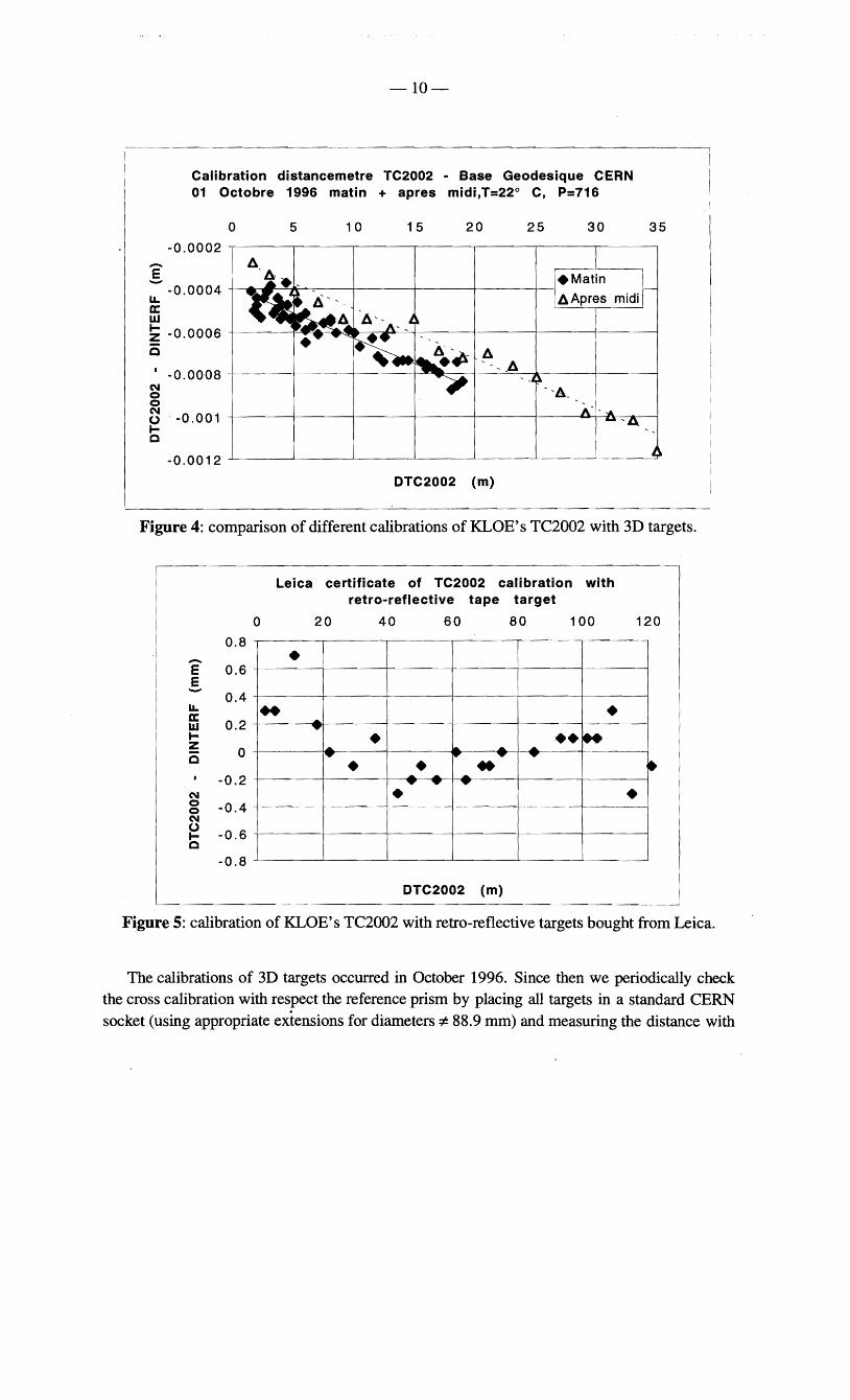

bull bull
bull bull
bull bull bull bull bullbullbullbullbullbullbullbullbullbullbullbullbullbullbullbullbullbullbullbullbullbullbullbullbullbullbullbullbullbullbullbullbull
bull bull
bullbull
bull bull
-31shy
200
bull 150 bull
Phi == O
100
50 bull
o
-50
bull -100
bull bull-150
-200 -2000 -1500 -1000 -500 o 500 1000 1500 2000
DeltaB vs Z
Figure 17 KLOE superconducting coil DeltaB (Gauss) vs z (mm)
Fig 17 shows DeltaB vs z up to 10 cm out of the external faces of the yoke poles Note that positive and negative zs are only approximately equal in absolute value which can be a relevant source of systematic error in regions where Bz gradients vs z are large For this reason the z coordinate is measured with the TC2002 infrared-beam distancemeter The good forward (zltO) - backward (zgtO) symmetry of DeltaB shows the good alignment of the MagAx with the magnetic axis of the superconducting coil produced by Oxfod Instruments for KLOE
-32shy
Azimuthal variation of Bz at r=75 mm from axis at z of yoke poles
2260
2258 -til tils 2256 ca
CJ- 2254 N m
2252
I l2250 bull o 90 180 270
Azimuth (degrees)
Figure 18 the small measured ltIgt-asymmetry of the field longitudinal component Bz in the yoke poles (2 Gauss in the vertical 0deg-180deg plane and 3 Gauss in the horizontal 90deg-270deg plane with respect to averages)
Fig 18 shows Bz vs ltIgt in the pole regio1s This infonnati~~ together with knowledge of the Bz radial gradient at that z and r indicates that the true field axis is offset by lt 05 mm in the transverse plane and with respect to the axis of the MagAx This is fUlTy consistent with the quoted survey accuracy and the MagAx geometrical accuracy The alignment accur(lcy of the KLOE superconducting solenoid is lt 02 mrad
8 THREE-DIMENSIONAL MAP OF THE MAGNETIC FIELD The full set of KLOE magnetic measurements was completed on October 9 1997 with the
3D map of the inner yoke volume for radiigt 145 mm from the axis measured by the MagAx Technical details and scope of mapping detector solenoids are by now well known and described in detail in the literature for example in ref [5] Mapping was done with the CERN machine used for the OPAL experiment at LEP slightly modified to be capable of reaching the region of Eme photomultipliers (in addition to the drift chamber tracking volume) in the pole regions The shape of the field in the poles is relevant because photomultipliers are sensitive to magnetic field components nonnal to their axis of the order of 300 Gauss To cover the full volume the machine needs to be reversed and an overlapping region must be measured to nonnalize and connect positive and negative z volumes One NMR probe located at the center of
the device gives the absolute normalization of our field and cross-calibrates other two Hall probes pennanently positioned in the middle and at the end of the cryostat inner surface Variations of the field value will be monitored in the future with these two Hall probes
-33shy d alignment
eometrical accuracy an C and machine showed that 1tS g e uate for mapping the D r
A detailed survey of th1S d 0(1) rorad in angle ad q 6 45 and 3 KGauss Afte in length an ed at about 005 1n the
tolerance 1S 0(1) ~ The solenoid was mapp normalization error of photomultiplier re~10ns f the machine we found a Bz
d re_al1gnment 0 invers10n an ossible faults m10nlzllt08 m overlap reg f data taking to check for p asurement
started already at the umeo results indicate that the me the Analysis of the data n of the mapper Prehnun~ ill 0 rate undisturbed by
the installation and operatlo r hed that photomultipliers w pe trically less accurate are has been successfully accomp 1S ~s at small radii although geom
e
netic flled and that data from pro mag M Ax measurements consistent w1th ag
ey9 CONCLUSION AND AC~NO~~~ creation of a dedicated suv and
The construction and installation 0 D n The work reported in this reVlew was alignment facility in the LNF Rese~chtt11VllSl0 ~an two years and it was successful as all
of 3 FfE in Ii e ess bl middotth ut the completed by a manpower hievement would not have been POSSl e Wl 0 task requirements were satlsf1ed ThiS ru we to G Capon and J Lee-Franzini helpful
Franzini and S BertolucCI We 0 support 0f P suggestions and comments on the content of this reView
We are indebted to M Mayoud C Lasseur JC Gayde and T LeMaire of the C~~ survey group for helpful teachings and suggestions for one month of hands-on trmnlng
experience at CERN and for providing KLOE with LGC and CARNET We learnt a lot o~ subjects related to the construction of the KLOE drift chamber and iron yoke from G PetruccI
of CERN who was KLOE consultant in the critical phase of the experiment design
We thank F Iungo and G Delle Monache of the LNF Accelerator Division for their help in the preparation of the magnetic measurements and for the design and construction of the
MagAx respectively We especially thank G Vignola Director of the LNF Accelerator Division and of the DAcvNE project for his supervision and encouragement during the actual performance of the KLOE magnetic axis measurement
10 REFERENCES [1] The KLOE Collaboration The KLOE Detector Technical Proposal LNF-93002 [2] The KLOE Collaboration The KLOE Central Drift Chamber Technical Proposal LNFshy
94028 [3] S DellAgnello at aI Status of the Construction of the KLOE Drift Chamber Nucl
Phys B (Proc Suppl) 54B (1997) 57-65 S Moccia The KLOE Drift Chamber End Plates KLOE public note (October 1997)
[4] V Ella at aI Stringing of the KLOE Drift Chamber at LNF Nucl Phys B (Proc Supp) 54B (1997) 66-69
[5] D Newton The Magnetic Field Mapping of Detector Magnets Proc of the CERN Accelerator School Montreux Switzerland March 1992
[6] D Newton Detector Magnet Measurements Proc of the CERN Accelerator School Anacapri Italy April 1997
-34_ APPENDIX A
EXPERIMENT RAILS AND PERMANENT SURV
Two important EY NETWORK access ones of th
bull the experiment r I e assembly hall are at s POsItIoned N
mm horizontal co-planan In ovember 1996 with an ali bull the pennanent survey netod 1~nun ~allelismlstraightness gDment tolerance of 05
whIch We Installed and The ratls consist oforth measured in March 1997
fOnning a 64 m by 3 6 ogonal short and long segments Th
towards DAqNE Withth ~ rec~angle The long segment~ wy crlo~s In the middle of the hall
of th err vertical symm re atd running fj e accelerator passing fJ_ h etry plane coincident with th rom the hall
Ii n uuoug KLOE e vertical median 1 e erence system is a Ii S Interaction region The p ane
pp OXlmately at the center of the I I ongIn of the networkm honzontal distanc ti rat s rectangle and t 1 e rom the center of DA4gtNE Th 1 IS ocated at about 32
honzontaJ and it is approximately coincident Wi~ th e network y axis is vertical the x axis is segments Note that while Sitting on the rail th e vertIcal symmetry plane of the long rail
fmal location in DAcIWE A non-trivial ruu enter of KLOE is about 15 m lower than its positioning KLOE on the beam l gI gnment system IS under construction for
Ine
b The net~Ork consists of 20 survey points half at ground level and half at a vertical level of a out two thIrds ofKLOEs height (- 5 m) Six of the survey points at top level were brackets
for s~andard CERN reference targets of the non-foldable type since they were located in
POSItIons accessed only by surveyors The remaining network points were instead of the
removable type since they had to be positioned in high traffic The KLOB assembly hall is so
small that we could not even afford using foldable brackets which are so common in the LEP
experimental halls at CERN On the contrary the brackets we adopted (made of a anodized AI)
are mounted by means of their two pins and three precisely machined 2cmx2cm flat contact
surfaces on a 2 cm thick Al plate fixed to the wall The bracket has a 30 mm precision hole with a 1200 chamfer which can accommodate a Taylor-Hobson target (and any other of our 3D
targets by means of suited rallonges) the TC2002 and the Distinvar The manufacturer guarantees that the distance of the 30 mm holes of two such brackets can be measured with the invarlDistinvar with a systematic error due to the Distinvar pulling force lt01 mm This is about
a factor 2 worse than the error typical of this technique and it applies to the worst case of the invar wire stretched normal to the brackets These removable brackets also have a separate 10 mm diameter hole which can accommodate a Taylor-Hobson with a special support and the TC2002 thanks to a special accessory for TC2002 forced centering (an index is engraved on the surface of the bracket) The special support and the special accessory are sold together with the
bracket plus plate These brackets are very versatile objects which we systematically mounteddismounted beforeafter almost every survey (one of them got hit and the pins damaged when we left them in position) We also moved them often from one plate to the other since we bought 5 brackets but bought and installed 14 fixed plates The drawback when using these objects is that each plate has to be fixed carefully to the wall in such a way that the 30 mm
35shy
and 10 mm holes are vertical as no verticalization is possible after their installation differently from CERN-style reference-target brackets
With LGC we estimate the accuracy in the determination of the position of the network points as ~O2 mm The naming and the coorcinates of all network points are given in KLOE internal memo 121
By the time of KLOEs installation in DAltlgtNE the network will be about 14 months old So far we did not observe sinking and aging effects of the network We did however observe a 18 mm movement along the rails of the KLOE yoke + solenoid with respect to the network following the series of earthquakes which occurred in central Italy in October and early November 1997