webbuilder3.asiannet.com · solar panels can also be connected to the combiplus through optional...
TRANSCRIPT


Rich Electric Co. “CombiPlus” User Manual V7.19 Copyright 2009 Page 2

Rich Electric Co. “CombiPlus” User Manual V7.19 Copyright 2009 Page 3
Table of CONTENTS
Introduction..................................................................................................................................... Features...................................................................................................................... 7 Layout ........................................................................................................................ 8 About CombiPlus ...................................................................................................... 9 Specifications ........................................................................................................... 10 Dimensions............................................................................................................... 13 Chapter 1 Installation..................................................................................................................... 1.1 Box Contents...................................................................................................... 17 1.2 Location ............................................................................................................. 18 1.3 Requirements..................................................................................................... 19 1.4 Connection of Battery Cables .......................................................................... 19 1.5 Connection of AC Cabling ............................................................................... 20 1.6 AC Cabling Schematic Layout (Multiple Ciruits AC Output)..................... 22 1.7 AC Cabling Schematic Layout (Single Ciruit AC Output)........................... 23 1.8 Second Battery .................................................................................................. 24 1.9 Voltage Sense..................................................................................................... 24 1.10 Battery Temperature Sensor (BTS-3)........................................................... 24 1.11 Three Sets of Automatic Relays (RY1,RY2,RY3) Outputs......................... 24 1.12 Parrellel Conection ......................................................................................... 24 1.13 3-Phase Operation........................................................................................... 25 1.14 MEN (Main Earth Neutral) Grounding ....................................................... 25 1.15 Remote Control Panel (RCP-4) ..................................................................... 25 1.16 Ventilation (Standard Single Unit)................................................................ 26 1.17 Ventilation (Optinal Fan Cover Application) "Standard Single Unit" ..... 26 1.18 Ventilation (Multible or 3-Phase Appliaction) ............................................. 27

Rich Electric Co. “CombiPlus” User Manual V7.19 Copyright 2009 Page 4
Chapter 2 Wiring ............................................................................................................................ 2.1 Lower Front Panel Connections ...................................................................... 28 2.2 Battery "Star Connection" Schematic............................................................ 30 2.3 Battery "Rail Connection" Schematic ............................................................ 31 2.4 AC ParrellelConnection Schematic................................................................. 32 2.5 AC 3-Phase Conection Schematic.................................................................... 33 2.6 AC 3-Phase System 15 Modules....................................................................... 34 Chapter 3 Battery Types ................................................................................................................ 3.1 Sealed Batteries ................................................................................................. 35 3.2 AGM................................................................................................................... 35 3.3 Gel....................................................................................................................... 36 3.4 Flooded Batteries .............................................................................................. 36 3.5 Lead-Calcium .................................................................................................... 37 3.6 Lead-selenium ................................................................................................... 37 3.7 Lead-Antimony ................................................................................................. 37 Chapter 4 Operation....................................................................................................................... 4.1 Front Panel Display .......................................................................................... 38 4.2 Front Panel Button Operations ....................................................................... 40 4.3 Main Menu ........................................................................................................ 42 4.4 Main Menu: Programing "Operation" .......................................................... 43 4.5 Main Menu: Programing "Key Selections" ................................................... 45 4.6 Main Menu: Operation "Monitor"................................................................. 46 4.7 Main Menu: Operation "Fault Trace" ........................................................... 49 4.8 Main Menu: Operation "Fault History" ........................................................ 52

Rich Electric Co. “CombiPlus” User Manual V7.19 Copyright 2009 Page 5
Chapter 5 Mode Settings ................................................................................................................ 5.1 Four Control Modes Applicatioin ..................................................................... 54 MODE 1: AC Power as Priority Support ......................................................... 55 MODE 2: AC Generator Support with Dynamic Power Shifting.................. 60 5.2 Green Power Smart Feature .............................................................................. 64 MODE 3: Renewable Energy with Power Support ......................................... 66 MODE 4: Renewable Energy with AC Charger Backup Support................. 70 Chapter 6 Programming ................................................................................................................ A Group: Initialize.................................................................................................... 74 B Group: General ..................................................................................................... 77 C Group: Inverter..................................................................................................... 86 D Group: Battery Charger....................................................................................... 88 E Group: Aux-Relay ................................................................................................. 92 O Group: Operator................................................................................................... 43 U Group: Monitor..................................................................................................... 46 Chapter 5 User Constants "Flow Chart" ................................................................................. 99 Chapter 5 Constants List.......................................................................................................... 109 U Group: Monitor................................................................................................... 110 A Group: Initialize.................................................................................................. 110 B Group: General ................................................................................................... 110 C Group: Inverter................................................................................................... 112 D Group: Battery Charger..................................................................................... 113 E Group: Aux-Relay ............................................................................................... 113 F Group: Solar Charger......................................................................................... 118 O Group: Operator................................................................................................. 118 Chapter 9 Trouble Shooting Table.......................................................................................... 124

Rich Electric Co. “CombiPlus” User Manual V7.19 Copyright 2009 Page 6
Appendix A: EMC for Wall-Mounting/Vertical CombiPlus Appendix B: LVD for Wall-Mounting/Vertical CombiPlus Appendix C: C-Tick for Wall-Mounting/Vertical CombiPlus Appendix D: EMC for Table-Mounting/Horizontal CombiPlus Appendix E: LVD for Table-Mounting/Horizontal CombiPlus Appendix F: C-Tick for Table-Mounting/Horizontal CombiPlus

Rich Electric Co. “CombiPlus” User Manual V7.19 Copyright 2009 Page 7
Introduction
The Ultimate Interactive DC to AC Inverter/Charger Power Management Control System ideally designed for Home, Boat, Caravan or RV.
Features:
Intelligent Mains Grid Power and Generator Power Management Control. ATS Uninterrupted AC power Transfer Switch (UPS function). Two and Three phase AC output capability, for the more demanding loads*. Power Support Feature: boosting the capacity of shore or generator power, Power Shifting Feature: avoids sudden loads on generator causing voltage spikes. Interactive Power Sharing: programmable AC input control system Four stage adaptive charging system with dual bank battery charging,
up to 140Amps & 4 Amps starter battery. Programmable auxiliary relay contacts (x3) Solar charging capacity up to a massive 1920Amps*. Remote control replica of main control panel with LCD display*. Power Stack, Need more power?
Just keep stacking! for increased power upgrade*. “Green Power Smart” This feature is designed to conserve energy
when connected to the mains grid supply or AC Generator. Powerful Interactive Bi-Directional True Pure Sine Wave Inverter / Charger.
*Requires optional accessories, please see installation section for more information.

Rich Electric Co. “CombiPlus” User Manual V7.19 Copyright 2009 Page 8
Layout:

Rich Electric Co. “CombiPlus” User Manual V7.19 Copyright 2009 Page 9
About CombiPlus:
The “Combi” Functional Interactive Bi-Directional Inverter has a dual function. This unit can operate as a battery charger or as a power inverter. The system utilizes sophisticated circuitry to manage and control your power requirements. The CombiPlus is ideally designed for your car, boat, recreational vehicle or basically anywhere mains power is required. The CombiPlus features a powerful true pure sine wave inverter that converts DC battery voltage to AC high voltage producing a clean, smooth power output, Ideal for the most sensitive electronic equipment. This superior, extremely efficient power conversion system will run even the most demanding mains operated appliances when the grid power is unavailable. CombiPlus also has a powerful 4 stage battery charger that is capable of delivering up to a Huge 140 Amps. (3000watt , 12v Model) There is also a 4 Amp charging output great for keeping the starter battery in an RV or Generator constantly charged. Solar Panels can also be connected to the CombiPlus through optional SunStar® SS-45/60 or MPPT SunStar® controller allowing the batteries to be recharged giving you even more flexibility when you are away from mains powered sites. The CombiPlus has many unique features like its big brother the “SuperCombi”. This includes stacking for increased power output, 3 phase power option, (Requires optional parallel or 3-Phase modules and additional CombiPlus units). Power Support, where the input supply from an AC generator and the inverter can be combined together to support heavy start-up loads such as air-conditioners. Interactive Power Sharing, where the AC input supply can be programmed to a Maximum limit; this will protect against unwanted power tripping from the mains supply. For example, If you turn on an electric jug and air-conditioner at the same time, the shore power circuit breaker will likely trip leaving you without power, with the Combi’s Smart Power Management System will then use its Power Support feature to boost the mains input by using the Inverters output and shore power input together until the load decreases. The CombiPlus also offers automatic switching between the mains AC and the inverter known as an Auto Transfer Switch or ATS. This will provide a seamless power switch over between the mains input and the inverter power so no manual switching is required, CombiPlus does it all for you. CombiPlus can also automatically start your compatible backup generator in the case of a low battery or excessive high load usage and then turn the generator back off when not required.

Rich Electric Co. “CombiPlus” User Manual V7.19 Copyright 2009 Page 10
Specifications
MODEL
12 Volt System
24 Volt System
48 Volt System
CP-1500-12X (1)
CP-1500-24X
CP-1500-48X
CP-3000-12X (1)
CP-3000-24X
CP-3000-48X
GENERAL
Ventilation Fan Forced cooling Fan Forced cooling
Temperature
– Operation
– Storage
-20℃~ +70℃
-25℃~ +80℃
-20℃~ +70℃
-25℃~ +80℃
Protection
a. Output short circuit b. Over load
c. Battery voltage too high d. Battery voltage too low
e. DC voltage ripple too high f. Temperature Sensor Transformer (105℃) (105℃) Electronic & Powerstage (70℃) (70℃) Battery Temp BTS-3 (50℃) (50℃) Humidity 0~95% (non condensing) 0~95% (non condensing)
Power support Function Power shifting Function Uninterrupted AC power (less than 10 msec) (less than 10 msec) Adaptive 4-stage charge Two output to charge 2 battery banks Auxiliary Relay X 3 X 3
Parallel operation (Requires optional CP-PX) (Max. 5 sets) (Max. 5 sets) 3-phase capacity (Requires optional CP-3PX) Battery voltage sensor Battery Temperature sensor (BTS-3 Optional) Remote control port Extension Port (Port C)

Rich Electric Co. “CombiPlus” User Manual V7.19 Copyright 2009 Page 11
INVERTER
Input Voltage Range (VDC) 12V-(9.5 -16V) / 24V-(19-32V) / 48V-(38-64V)
Output Voltage (VAC) 210~245 VAC / 94~128 VAC
Output Frequency 50Hz /60Hz ± 0.1%
Output Waveform True Pure Sinewave
Output Voltage THD < 5%
Power Factor (All Loads)
No linger load, crest factor 3: 1
Cont. Power Output @ 70℃ (W)
Under 70℃ (cosθ=1.0)
1500Watt
(No derate 70℃ )
3000Watt
(No derate 70℃)
Cont. Power Output (W)
Over 70℃ (cosθ=1.0)
0W
(Shutdown)
0W
(Shutdown)
Maximum Power (W) 3000Watt 6000Watt
Maximum Efficiency (%) 82/84/85 84/86/89
Zero-load Power (W) (8W Power Save) 12W (Normal) (12W Power Save) 18W (Normal)
CHARGER
Input Voltage Range (VAC) 180~265 VAC / 94~138 VAC
Input Frequency 45-55Hz /55-65 Hz
Power Factor 1
Charge Characteristic 4-stage adaptive / Bulk-Absorption-Float-Equalize + Safe
Maximum DC Voltage Ripple (Vrms) < 1.25 V
Charge Current House Battery (A) 70A/40A/20A 140A/70A/40A
Charge Current Starter Battery (A) 4A
Output Charging Voltage (VDC) 12~16V / 24~32V / 48~64V
Absorption Voltage Default (VDC) 14.4V / 28.8V / 57.6V
Float voltage Default (VDC) 13.8V / 27.6V / 55.2V
Equalize Voltage default (VDC) 13.2V / 26.4V / 52.8V
Output Charge Voltage (min ~ max) 8V~16V / 11V~32V / 22V~64V
Battery Temperature sensor BTS-3 (optional)

Rich Electric Co. “CombiPlus” User Manual V7.19 Copyright 2009 Page 12
(1) X should be 1, output voltage = 94~128 VAC or 2, output voltage = 210~245 VAC Specifications subject to change
AC INPUT SWITCH
AC IN Internal Terminal Circuit Breaker 1500w: 30A -(110V) 15A -(230V)
3000w: 60A -(110V) 30A -(230V)
AC IN Auto Transfer Switch Current 1500w: 32A- (110V) 16A -(230V)
3000w: 63A -(110V) 32A -(230V)
Switch-over Time
a. inverter to AC input 0 msec.
b. AC input to inverter 0 msec.
Detection Time AC Input Fault 4 ~10 msec.
Trip Level AC Low Input to Inverter Default Setting: 94 VAC (94~120V) 110v Model
180 VAC (180~230V) 230v Model
Trip Level Inverter to AC Low Input Default Setting: 101 VAC (95~121V) 110v Model
187VAC (181~231V) 230v Model
Trip Level Inverter to AC High Input Default Setting: 138 VAC (119~142V) 110v Model
265 VAC (229~269V) 230v Model
Trip Level AC High Input to Inverter Default Setting: 143 VAC (120~143V) 110v Model
270 VAC (230~270V) 230v Model
Min.~ Max. Frequency Range 45-55 Hz / 55-65 Hz
MECHANICAL
Cabinet / Protecting Class Aluminum / IP20
Dimension (HXWXD) 362 x 258 x 370 mm 424 x 258 x 370 mm
Weight (kgs) 21 kgs 27 kgs

Rich Electric Co. “CombiPlus” User Manual V7.19 Copyright 2009 Page 13
Dimensions
Dimensions 1500watt Model
Dimension for Wall Mounting/Vertical CombiPlus 1500W CP-1500W-12/24
Unit: mm
AC IN CHARGER
SOLARCHARGER
SOLARPANEL
INVERTER AC OUT
ATS
POWER
Invertek CombiPlus
DSPL
ENT
RUNSTOP
REMOTE
R
BATTERYBULK
ABSOR
FLOAT
COM. ERR.
1MODE
2MODE
3MODE
4MODE
ERR.
COM.
1
0
Power Management Control System

Rich Electric Co. “CombiPlus” User Manual V7.19 Copyright 2009 Page 14
Dimensions 1500watt Model
Installation Holes for Wall Mounting/Vertical CombiPlus 1500W CP-1500W-12/24
Backside Mounting Holes Bottom Mounting Holes
10
1010
10M6-4
M8-4

Rich Electric Co. “CombiPlus” User Manual V7.19 Copyright 2009 Page 15
Dimensions 3000watt Model
Dimension for Wall Mounting/Vertical CombiPlus 3000W CP-3000W-12/24
Unit: mm
AC IN CHARGER
SOLARCHARGER
SOLARPANEL
INVERTER AC OUT
ATS
POWER
Invertek CombiPlus
DSPL
ENT
RUNSTOP
REMOTE
R
BATTERYBULK
ABSOR
FLOAT
COM. ERR.
1MODE
2MODE
3MODE
4MODE
ERR.
COM.
1
0
Power Management Control System

Rich Electric Co. “CombiPlus” User Manual V7.19 Copyright 2009 Page 16
Dimensions 3000watt Model
Installation Holes
Backside Mounting Holes Bottom Mounting Hole
10
1010
10M6-4
M8-4

Rich Electric Co. “CombiPlus” User Manual V7.19 Copyright 2009 Page 17
Chapter 1 Installation
This product should be installed by a qualified electrician. ALL AC WIRING MUST BE CARRIED OUT BY A LICENSED
ELECTRICIAN AND MUST CONFORM TO AS3000 WIRING REGULATIONS OR RELEVANT STANDARDS
For other regions, the installation and wiring should comply with relevant National Standards and Practices.
1.1 Box Contents
CombiPlus USER MANUAL Quick Reference Guide Warranty Card Bag Containing connection items, Four M8 mounting bolts (including spring washers) Four DC terminals and casing

Rich Electric Co. “CombiPlus” User Manual V7.19 Copyright 2009 Page 18
1.2 Location
This product must be installed in a dry and well-ventilated area, as close as possible to batteries. There should be a clear space of at least 20 cm around the appliance for cooling.
Excessively high ambient temperature will result in the following
Reduced service life Reduced charge current Reduced peak capacity or shutdown of the inverter
Never position the inverter directly above the batteries. CombiPlus is suitable for wall mounting. The back and the bottom of the enclosure Has holes for wall mounting purposes. The front of CombiPlus must remain accessible after installation. Ensure the AC and DC input cables are fitted with fuses and circuit breakers. Try and keep the distance between the product and battery to a minimum in order to minimize cable voltage losses. The system should always be earthed for lightning and to reduce the risk of accidental short circuits, Earthing the DC Power Wiring is not normally required. If the system is installed in a lightning prone area then protection for the earthing of the DC wiring may be needed. DC Earth cables must be capable of caring the battery fault current and trip the battery fuse before the cabling fails. A Battery Fuse or Circuit Breaker is required at all times; Never connect the CombiPlus directly to the battery. The fuse or Circuit breaker should be connected as close to the battery as possible. If the batteries are not earthed then protection should be provide on both the Positive and Negative sides of the battery. NOTE: The DC cabling should always be kept separated from any of the AC cabling.

Rich Electric Co. “CombiPlus” User Manual V7.19 Copyright 2009 Page 19
1.3 Requirements
Screwdrivers for removing the lower-front panel and connecting AC loads. 2x battery cables (maximum length 6 meters) ensure battery cables are correctly sized. Insulated box spanner (13 mm) for securing the DC terminal nuts. Twin and Earth power cable for AC cabling.
1.4 Connection of Battery Cables
Ensure you have enough battery capacity to be able to operate your CombiPlus to its full capacity.
Model Item
CP-1500-12X CP-1500-24X CP-3000-12X CP-3000-24X
Minimum Battery Capacity (Ah)
200Ah 100Ah 400Ah 200Ah
Recommended Cable Size (mm2)
53.5 mm2
0 AWG 33.6 mm2
2 AWG 85 mm2
000 AWG 53.5 mm2
0 AWG NOTE: Consult your battery manufacturer for correct battery sizing for your application, Battery cable sizes are based on recommended cable length of 2 meters. Longer cable lengths will require large cable sizes. Always use an insulated box spanner in order to avoid shorting the battery. Never short the battery cables!
Remove the four screws at the lower-front panel of the enclosure and remove the panel. Connect the battery cable: the + (red) on the right and the – (black) on the left. Don’t reverse the (+) and (-) of the battery. This may cause internal damage. Secure battery nuts tightly in order to reduce the contact resistance as much as possible.
For more information on battery bank enclosures and installations please refer to AUS/NZ standards
AS 2676, AS4509, AS3010 & AS4086. For other regions, the installation and wiring should comply with relevant
National Standards and Practices.

Rich Electric Co. “CombiPlus” User Manual V7.19 Copyright 2009 Page 20
1.5 Connection of AC Cabling
Ensure the CombiPlus is grounded for safety. The main earth screw has been fitted at the bottom left side of the enclosure. The AC terminal connection is located in lower-front panel of the enclosure: The AC Supply (AC IN) cable must be connected to AC IN terminals, Use a Twin and Earth power cable; refer to table below for correct AC cable sizes.
The AC output terminal connection is labeled “AC OUT”. The terminal points are indicated
clearly. From left to right: “G” (earth), “N” (neutral), and “L” (phase). The AC input terminal connection is labeled “AC IN”, The terminal points are indicated clearly: From left to right “L” (phase), “N” (neutral), and “G” (earth).
External fuses or circuit breakers must be installed. The AC input circuit breaker built in to the CombiPlus is designed to protect the internal wiring inside the unit only. Faults on sub circuits will not normally trip this breaker. All External AC wiring must be protected with suitably rated external circuit breakers and RCD Earth Leakage protection. For AC input protection we recommend the use of a Circuit Breaker (MCB). The electricity which is switched through to the Inverters output (AC OUT) is NOT fused. External fuses or circuit breakers must be installed. For correct sizing see table below. AC output Circuit breakers and Earth Leakage protection is recommend for Protection of the AC output from the Inverter.

Rich Electric Co. “CombiPlus” User Manual V7.19 Copyright 2009 Page 21
Inverter AC Input CombiPlus®
MCB/RCD
MIN AC Cable Size
single Twin‐core and earth
Model MAX Circuit Breaker Current Enclosed conduit Unenclosed free air
1500watt 16Amp 2.5mm 1.5mm
3000watt 32Amp 6mm 4mm
6000watt 63Amp 16mm 10mm
Inverter AC Output CombiPlus®
MCB/RCD
MIN AC Cable Size
single Twin‐core and earth
Model MAX Circuit Breaker Current Enclosed conduit Unenclosed free air
1500watt 25Amp 4mm 2.5mm
3000watt 50Amp 16mm 10mm
6000watt 100Amp 35mm 25mm
THE OUTPUT VOLTAGE FROM THE INVERTER IS LETHAL For your safety ensure that all installations meet and comply with the relevant
requirements of AS3000 wiring standards and AC wiring is installed by a Licensed Electrical Contractor.
MAKE SURE THE COMBIPLUS IS SWITCHED OFF AND DISCONECTED FROM ALL AC AND DC SUPPLIES BEFORE WORKING ON THE SYSTEM!
Rich Electric Co. “CombiPlus” User Manual V7.19 Copyright 2009 Page 22
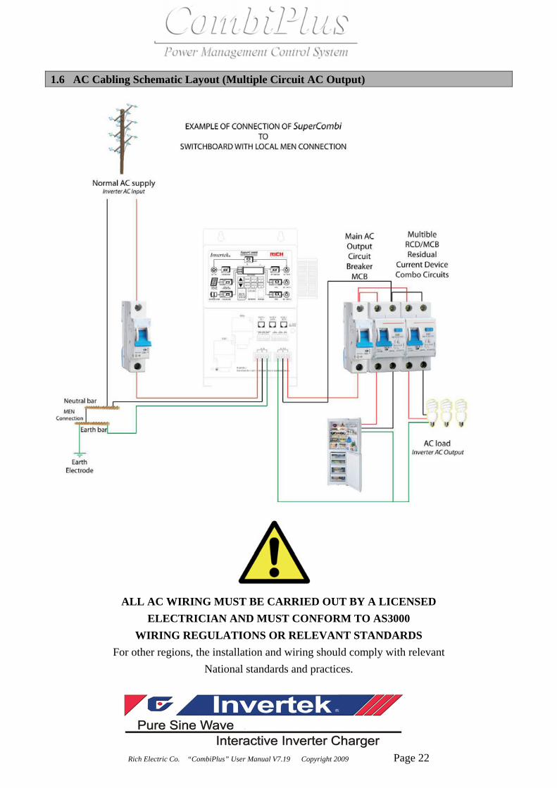
1.6 AC Cabling Schematic Layout (Multiple Circuit AC Output)
ALL AC WIRING MUST BE CARRIED OUT BY A LICENSED ELECTRICIAN AND MUST CONFORM TO AS3000
WIRING REGULATIONS OR RELEVANT STANDARDS For other regions, the installation and wiring should comply with relevant
National standards and practices.

Rich Electric Co. “CombiPlus” User Manual V7.19 Copyright 2009 Page 23
1.7 AC Cabling Schematic Layout (Single Circuit AC Output)
ALL AC WIRING MUST BE CARRIED OUT BY A LICENSED ELECTRICIAN AND MUST CONFORM TO AS3000
WIRING REGULATIONS OR RELEVANT STANDARDS For other regions, the installation and wiring should comply with relevant
National standards and practices.

Rich Electric Co. “CombiPlus” User Manual V7.19 Copyright 2009 Page 24
1.8 Second Battery The “CombiPlus” has a secondary output connection for charging a starter battery. For connection, see page 28
1.9 Voltage Sense If you have long battery cable runs we recommend you use the voltage sense input. By
connecting wires of at least 0.75 mm2 from the battery to the VS input the CombiPlus can monitor the correct battery voltage. For connection, see page 28.
1.10 Battery Temperature Sensor (BTS-3) The battery temperature sensor (optional) is recommended for correct temperature
compensated battery charging and battery over temperature protection, see page 28. The sensor is insulated and must be mounted on the batteries minus pole.
1.11 Three Sets of Auxiliary Relay (RY1, RY2, RY3) Output The “CombiPlus” provides 3 sets of Auxiliary Relays for users to connect to other
appliances or to output the alarm signals. 3 sets of relays can be programmed for respective function.
(E Group Constants) and can be practically applied which is one of the greatest features. 1.12 Parallel Connection
The CombiPlus can be connected in parallel using multiple identical units, please see page 32. The batteries must be connected in accordance with page 30 & 31.This requires a CP-PX, parallel box, to be purchased separately.
Note:
• We recommended No more than 5 units should be connected in parallel. • Use the same model CombiPlus when connecting in parallel. • Make sure you have enough battery capacity to support the number of CombiPlus
Units. • Install the CombiPlus units next to each other making sure there is adequate clearance
for ventilation of at least 20 cm. For better ventilation, please install the fan cover (optional).
• The Battery Temperature Sensor (BTS), voltage sensor (V-SENS) and remote control panel (RCP) must be connected to Master.
• The cables for each CombiPlus must be equal in length (AC and DC)

Rich Electric Co. “CombiPlus” User Manual V7.19 Copyright 2009 Page 25
1.13-Phase Operation The CombiPlus can be configured for use in a 2 or 3-phase applications, see page 33 & 34. This requires a CP-3PX, 3-Phase box, Purchased separately. The batteries must be connected in accordance with page 30 & 31. Note: • We recommended No more than 5 units should be connected in parallel. • Use the same model CombiPlus. • Make sure you have enough battery capacity to support all of the CombiPlus Units. • Install the CombiPlus units next to each other making sure there is adequate clearance
for ventilation of at least 20 cm. For better ventilation, please install the fan cover (optional).
• The Battery Temperature Sensor (BTS), voltage sensor (V-SENS) and remote control panel (RCP) must be connected to Master.
• The cables for each CombiPlus must be equal in length (AC and DC)
1.14 MEN (Main Earth Neutral) Grounding
When the AC input voltage is not present the CombiPlus will switch the neutral of “AC OUT” and connect it to the Earth (Ground) by means of a relay. This function can be disabled by constant B2-07 (B2-07=0 Disconnect)
1.15 Remote Control Panel (RCP-4) The CombiPlus can be operated remotely from remote port with the aid of a remote control panel. For connection of a remote control panel, see page 28. Note: The display panel and operation flow of the remote control panel is exactly the same as the upper-front display panel.

Rich Electric Co. “CombiPlus” User Manual V7.19 Copyright 2009 Page 26
1.16 Ventilation (Standard Single Unit)
When the unit is installed in an Environment with good ventilation, The fan cover is not needed.
1.17 Ventilation (Optional Fan Cover Application) “Single Unit Installed” When the unit is installed nearby wall side which Blocks the airflow coming to the unit, The fan cover is needed. The CombiPlus also supports connection of an External fan. This is very useful when the CombiPlus is installed in a cabinet or in Recreational Vehicle / Boat. Fan ON: E1-08, See page 92. Fan OFF: E2-08, See page 95. Aux-Relay 1 can be used to turn ON, when the internal fan switches on. E1-08: Fan ON for ? sec used together with the E2-08: Fan OFF for ? sec setting to control an external fan.

Rich Electric Co. “CombiPlus” User Manual V7.19 Copyright 2009 Page 27
1.18 Multiple and 3-Phase Application When there is more than one CombiPlus in parallel connection or 3-phase connection, the optional accessory, fan covers, are highly recommended to be installed for each CombiPlus to have better ventilation in cooling down the temperature.

Rich Electric Co. “CombiPlus” User Manual V7.19 Copyright 2009 Page 28
Chapter 2 Wiring Connections 2.1 Lower-Front Panel Connection for Wall-Mounting/Vertical CombiPlus
P
G
HI
O MN L J K
E F
A B C
D
Rich Electric Co. “CombiPlus” User Manual V7.19 Copyright 2009 Page 29
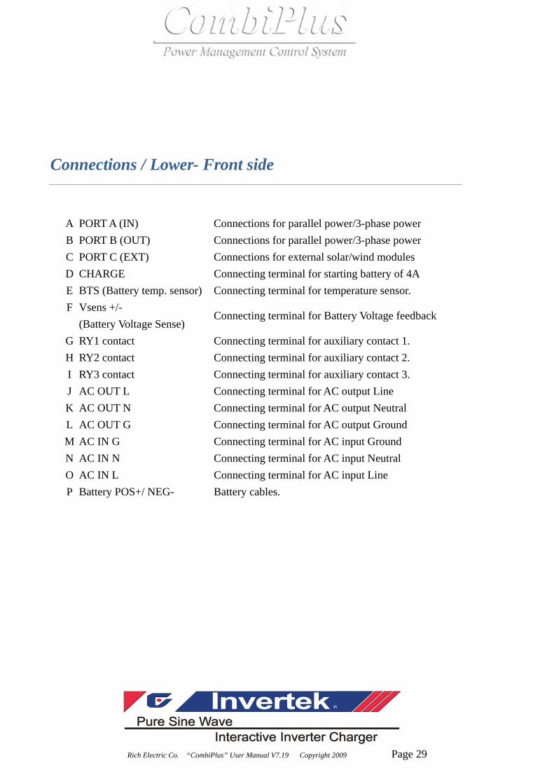
Connections / Lower- Front side
A PORT A (IN) Connections for parallel power/3-phase power B PORT B (OUT) Connections for parallel power/3-phase power C PORT C (EXT) Connections for external solar/wind modules D CHARGE Connecting terminal for starting battery of 4A E BTS (Battery temp. sensor) Connecting terminal for temperature sensor. F Vsens +/-
(Battery Voltage Sense) Connecting terminal for Battery Voltage feedback
G RY1 contact Connecting terminal for auxiliary contact 1. H RY2 contact Connecting terminal for auxiliary contact 2. I RY3 contact Connecting terminal for auxiliary contact 3. J AC OUT L Connecting terminal for AC output Line K AC OUT N Connecting terminal for AC output Neutral L AC OUT G Connecting terminal for AC output Ground M AC IN G Connecting terminal for AC input Ground N AC IN N Connecting terminal for AC input Neutral O AC IN L Connecting terminal for AC input Line P Battery POS+/ NEG- Battery cables.
Rich Electric Co. “CombiPlus” User Manual V7.19 Copyright 2009 Page 30
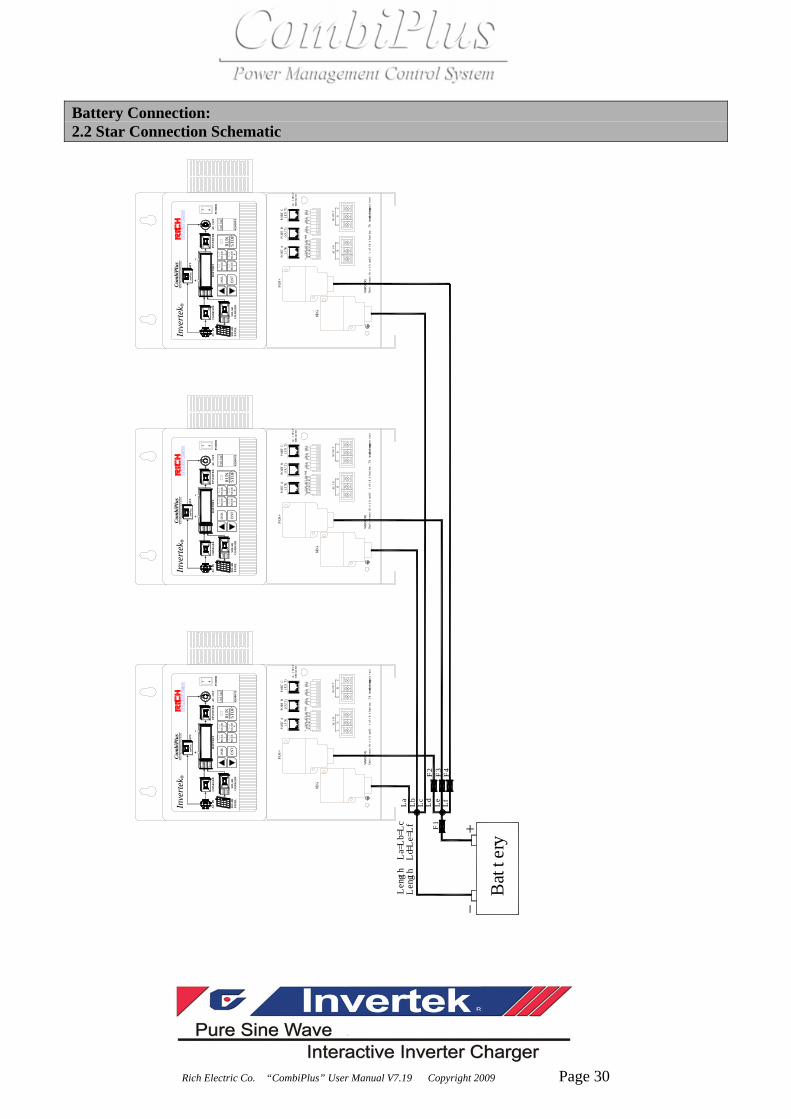
Battery Connection: 2.2 Star Connection Schematic
V-SENSBTSCHARGE
RY1
AC
RY2
AC
RY3
AC
POS+
NEG-
BB
AC INPUT
BREAKER
PORT A
(IN)PORT B
(OUT)PORT C
(EXT)
AC IN
LN
G
AC OUT
LN
G
WARNING:
Don't reverse the (+) and (-) of the battery.This may cause inte
rnal damage.
AC
IN
CH
AR
GE
R
SO
LA
RC
HA
RG
ER
SOL
AR
PAN
EL
INV
ER
TE
RA
C O
UT
AT
S
POW
ER
Inve
rtek
Com
biPl
us
DSP
L
ENT
RU
NST
OP
RE
MO
TE
R
BA
TT
ER
YBU
LK
ABS
OR
FLO
AT
CO
M.
ER
R.
1M
OD
E2
MO
DE
3M
OD
E4
MO
DE
ERR
.
CO
M.
1 0
Pow
er M
anag
emen
t Con
trol
Sys
tem
Battery
Length La=Lb=Lc
Length Ld=Le=Lf
LaLbLcLdLeLf
F1
F2F3F4
V-SENSBTSCHARGE
RY1
AC
RY2
AC
RY3
AC
POS+
NEG-
BB
AC INPUT
BREAKER
PORT A
(IN)PORT B
(OUT)PORT C
(EXT)
AC IN
LN
G
AC OUT
LN
G
WARNING:
Don't reverse the (+) and (-) of the battery.This may cause inte
rnal damage.
AC
IN
CH
AR
GE
R
SO
LA
RC
HA
RG
ER
SOL
AR
PAN
EL
INV
ER
TE
RA
C O
UT
AT
S
POW
ER
Inve
rtek
Com
biPl
us
DSP
L
ENT
RU
NST
OP
RE
MO
TE
R
BA
TT
ER
YBU
LK
ABS
OR
FLO
AT
CO
M.
ER
R.
1M
OD
E2
MO
DE
3M
OD
E4
MO
DE
ER
R.
CO
M.
1 0
Pow
er M
anag
emen
t Con
trol
Sys
tem
V-SENSBTSCHARGE
RY1
AC
RY2
AC
RY3
AC
POS+
NEG-
BB
AC INPUT
BREAKER
PORT A
(IN)PORT B
(OUT)PORT C
(EXT)
AC IN
LN
G
AC OUT
LN
G
WARNING:
Don't reverse the (+) and (-) of the battery.This may cause inte
rnal damage.
AC
IN
CH
AR
GE
R
SO
LA
RC
HA
RG
ER
SOL
AR
PAN
EL
INV
ERT
ER
AC
OU
T
AT
S
POW
ER
Inve
rtek
Com
biPl
us
DSP
L
ENT
RU
NST
OP
RE
MO
TE
R
BA
TT
ER
YB
ULK
ABS
OR
FLO
AT
CO
M.
ERR
.
1M
OD
E2
MO
DE
3M
OD
E4
MO
DE
ERR
.
CO
M.
1 0
Pow
er M
anag
emen
t Con
trol
Sys
tem

Rich Electric Co. “CombiPlus” User Manual V7.19 Copyright 2009 Page 31
2.3 Battery : Rail Connection Schematic
Battery
Length La=Lb=Lc
Length Ld=Le=Lf
La
Lb
Lc
Ld
Le
Lf
F1
F2
F3
F4
V-SENSBTSCHARGE
RY1
AC
RY2
AC
RY3
AC
POS+
NEG-
BB
AC INPUT
BREAKER
PORT A
(IN)PORT B
(OUT)PORT C
(EXT)
AC IN
LN
G
AC OUT
LN
G
WARNING:
Don't reverse the (+) and (-) of the battery.This may cause inte
rnal damage.
AC
IN
CH
AR
GE
R
SO
LA
RC
HA
RG
ER
SOL
AR
PAN
EL
INV
ER
TE
RA
C O
UT
AT
S
POW
ER
Inve
rtek
Com
biPl
us
DSP
L
ENT
RU
NST
OP
RE
MO
TE
R
BA
TT
ER
YB
ULK
AB
SOR
FLO
AT
CO
M.
ER
R.
1M
OD
E2
MO
DE
3M
OD
E4
MO
DE
ER
R.
CO
M.
1 0
Powe
r Man
agem
ent C
ontr
ol S
yste
m
V-SENSBTSCHARGE
RY1
AC
RY2
AC
RY3
AC
POS+
NEG-
BB
AC INPUT
BREAKER
PORT A
(IN)PORT B
(OUT)PORT C
(EXT)
AC IN
LN
G
AC OUT
LN
G
WARNING:
Don't reverse the (+) and (-) of the battery.This may cause inte
rnal damage.
AC
IN
CH
AR
GE
R
SO
LA
RC
HA
RG
ER
SOL
AR
PAN
EL
INV
ER
TE
RA
C O
UT
AT
S
POW
ER
Inve
rtek
Com
biPl
us
DSP
L
ENT
RU
NST
OP
RE
MO
TE
R
BA
TT
ER
YBU
LK
ABS
OR
FLO
AT
CO
M.
ERR
.
1M
OD
E2
MO
DE
3M
OD
E4
MO
DE
ERR
.
CO
M.
1 0
Pow
er M
anag
emen
t Con
trol S
yste
m
V-SENSBTSCHARGE
RY1
AC
RY2
AC
RY3
AC
POS+
NEG-
BB
AC INPUT
BREAKER
PORT A
(IN)PORT B
(OUT)PORT C
(EXT)
AC IN
LN
G
AC OUT
LN
G
WARNING:
Don't reverse the (+) and (-) of the battery.This may cause inte
rnal damage.
AC
IN
CH
AR
GE
R
SO
LA
RC
HA
RG
ER
SOL
AR
PAN
EL
INV
ER
TE
RA
C O
UT
AT
S
POW
ER
Inve
rtek
Com
biPl
us
DSP
L
ENT
RU
NST
OP
RE
MO
TE
R
BA
TT
ER
YB
ULK
ABS
OR
FLO
AT
CO
M.
ER
R.
1M
OD
E2
MO
DE
3M
OD
E4
MO
DE
ERR
.
CO
M.
1 0
Powe
r Man
agem
ent C
ontr
ol S
yste
m

Rich Electric Co. “CombiPlus” User Manual V7.19 Copyright 2009 Page 32
2.4 AC Parallel Connection Schematic
AC INL in
N in
PE
AC OUT
L out
N out
PE
MASTER
SLAVE 1
SLAVE 2
Parallel Box
V-SENSBTSCHARGE
RY1
AC
RY2
AC
RY3
AC
POS+
NEG-
BB
AC INPUT
BREAKER
PORT A
(IN)PORT B
(OUT)PORT C
(EXT)
AC IN
LN
G
AC OUT
LN
G
WARNING:
Don't reverse the (+) and (-) of the battery.This may cause inte
rnal damage.
AC
IN
CH
AR
GE
R
SO
LAR
CH
AR
GER
SOL
AR
PAN
EL
INV
ER
TER
AC
OU
T
AT
S
POW
ER
Inve
rtek
Com
biPl
us
DSP
L
ENT
RU
NST
OP
REM
OTE
R
BA
TTER
YB
ULK
AB
SOR
FLO
AT
CO
M.
ER
R.
1M
OD
E2
MO
DE
3M
OD
E4
MO
DE
ERR
.
CO
M.
1 0
Pow
er M
anag
emen
t Con
trol
Sys
tem
V-SENSBTSCHARGE
RY1
AC
RY2
AC
RY3
AC
POS+
NEG-
BB
AC INPUT
BREAKER
PORT A
(IN)PORT B
(OUT)PORT C
(EXT)
AC IN
LN
G
AC OUT
LN
G
WARNING:
Don't reverse the (+) and (-) of the battery.This may cause inte
rnal damage.
AC
IN
CH
AR
GER
SO
LA
RC
HA
RG
ERSO
LA
RPA
NE
L
INV
ERT
ERA
C O
UT
ATS
POW
ER
Inve
rtek
Com
biPl
us
DSP
L
ENT
RU
NST
OP
RE
MO
TE
R
BAT
TER
YBU
LK
ABS
OR
FLO
AT
CO
M.
ERR
.
1M
OD
E2
MO
DE
3M
OD
E4
MO
DE
ER
R.
CO
M.
1 0
Pow
er M
anag
emen
t Con
trol S
yste
m
V-SENSBTSCHARGE
RY1
AC
RY2
AC
RY3
AC
POS+
NEG-
BB
AC INPUT
BREAKER
PORT A
(IN)PORT B
(OUT)PORT C
(EXT)
AC IN
LN
G
AC OUT
LN
G
WARNING:
Don't reverse the (+) and (-) of the battery.This may cause inte
rnal damage.
AC
IN
CH
AR
GE
R
SO
LAR
CH
AR
GER
SOL
AR
PAN
EL
INV
ER
TER
AC
OU
T
AT
S
POW
ER
Inve
rtek
Com
biPl
us
DSP
L
ENT
RU
NST
OP
REM
OTE
R
BA
TTER
YB
ULK
AB
SOR
FLO
AT
CO
M.
ER
R.
1M
OD
E2
MO
DE
3M
OD
E4
MO
DE
ERR
.
CO
M.
1 0
Powe
r Man
agem
ent C
ontr
ol S
yste
m
Parallel Box
SLAVE 3
V-SENSBTSCHARGE
RY1
AC
RY2
AC
RY3
AC
POS+
NEG-
BB
AC INPUT
BREAKER
PORT A
(IN)PORT B
(OUT)PORT C
(EXT)
AC IN
LN
G
AC OUT
LN
G
WARNING:
Don't reverse the (+) and (-) of the battery.This may cause inte
rnal damage.
AC
IN
CH
AR
GER
SO
LA
RC
HA
RG
ERSO
LA
RPA
NE
L
INV
ERT
ERA
C O
UT
ATS
POW
ER
Inve
rtek
Com
biPl
us
DSP
L
ENT
RU
NST
OP
RE
MO
TE
R
BAT
TER
YBU
LK
ABS
OR
FLO
AT
CO
M.
ERR
.
1M
OD
E2
MO
DE
3M
OD
E4
MO
DE
ERR
.
CO
M.
1 0
Pow
er M
anag
emen
t Con
trol S
yste
m
Parallel Box
SLAVE 4
V-SENSBTSCHARGE
RY1
AC
RY2
AC
RY3
AC
POS+
NEG-
BB
AC INPUT
BREAKER
PORT A
(IN)PORT B
(OUT)PORT C
(EXT)
AC IN
LN
G
AC OUT
LN
G
WARNING:
Don't reverse the (+) and (-) of the battery.This may cause inte
rnal damage.
AC
IN
CH
AR
GE
R
SO
LAR
CH
AR
GER
SOL
AR
PAN
EL
INV
ERTE
RA
C O
UT
AT
S
POW
ER
Inve
rtek
Com
biPl
us
DSP
L
ENT
RU
NST
OP
REM
OT
E
R
BA
TTER
YB
ULK
AB
SOR
FLO
AT
CO
M.
ER
R.
1M
OD
E2
MO
DE
3M
OD
E4
MO
DE
ERR
.
CO
M.
1 0
Powe
r Man
agem
ent C
ontr
ol S
yste
m
Parallel Box
For t
he M
AST
ER, c
onst
ant B
2-05
and
B3-
01 m
ust b
e se
t.
For t
he S
LAV
E 1,
2, 3
and
4, c
onst
ant s
ettin
gs a
re n
ot re
quire
d.

Rich Electric Co. “CombiPlus” User Manual V7.19 Copyright 2009 Page 33
2.5 AC 3-Phase Connection Schematic
AC INL1L2
PE
AC OUT
N out
PE
MASTER
FOLLOWER 1
FOLLOWER 2
L3N in
L1
L2
L3
3-Phase Box
V-SENSBTSCHARGE
RY1
AC
RY2
AC
RY3
AC
POS+
NEG-
BB
AC INPUT
BREAKER
PORT A
(IN)PORT B
(OUT)PORT C
(EXT)
AC IN
LN
G
AC OUT
LN
G
WARNING:
Don't reverse the (+) and (-) of the battery.This may cause inte
rnal damage.
AC
IN
CH
AR
GER
SO
LA
RC
HA
RG
ER
SOL
AR
PAN
EL
INV
ER
TER
AC
OU
T
AT
S
POW
ER
Inve
rtek
Com
biPl
us
DSP
L
ENT
RU
NST
OP
RE
MO
TE
R
BATT
ERY
BU
LK
AB
SOR
FLO
AT
CO
M.
ER
R.
1M
OD
E2
MO
DE
3M
OD
E4
MO
DE
ER
R.
CO
M.
1 0
Pow
er M
anag
emen
t Con
trol
Sys
tem
V-SENSBTSCHARGE
RY1
AC
RY2
AC
RY3
AC
POS+
NEG-
BB
AC INPUT
BREAKER
PORT A
(IN)PORT B
(OUT)PORT C
(EXT)
AC IN
LN
G
AC OUT
LN
G
WARNING:
Don't reverse the (+) and (-) of the battery.This may cause inte
rnal damage.
AC
IN
CH
AR
GE
R
SO
LAR
CH
AR
GER
SOL
AR
PAN
EL
INV
ER
TER
AC
OU
T
ATS
POW
ER
Inve
rtek
Com
biPl
us
DSP
L
ENT
RU
NST
OP
REM
OTE
R
BA
TTE
RY
BU
LK
AB
SOR
FLO
AT
CO
M.
ER
R.
1M
OD
E2
MO
DE
3M
OD
E4
MO
DE
ER
R.
CO
M.
1 0
Pow
er M
anag
emen
t Con
trol
Sys
tem
V-SENSBTSCHARGE
RY1
AC
RY2
AC
RY3
AC
POS+
NEG-
BB
AC INPUT
BREAKER
PORT A
(IN)PORT B
(OUT)PORT C
(EXT)
AC IN
LN
G
AC OUT
LN
G
WARNING:
Don't reverse the (+) and (-) of the battery.This may cause inte
rnal damage.
AC
IN
CH
AR
GER
SO
LAR
CH
AR
GE
RSO
LA
RPA
NE
L
INV
ER
TER
AC
OU
T
ATS
POW
ER
Inve
rtek
Com
biPl
us
DSP
L
ENT
RU
NST
OP
REM
OT
E
R
BA
TTER
YB
UL
K
AB
SOR
FLO
AT
CO
M.
ER
R.
1M
OD
E2
MO
DE
3M
OD
E4
MO
DE
ER
R.
CO
M.
1 0
Pow
er M
anag
emen
t Con
trol
Sys
tem
3-Phase Box
3-Phase Box
MA
STER
con
stan
ts se
tting
: B
4-01
=1
B4-
02=1
B
4-03
=0
FOLL
OW
ER 1
con
stan
ts se
tting
: B
4-01
=1
B4-
02=0
B
4-03
=0
FOLL
OW
ER 2
con
stan
ts se
tting
: B
4-01
=1
B4-
02=0
B
4-03
=0

Rich Electric Co. “CombiPlus” User Manual V7.19 Copyright 2009 Page 34
2.6 AC 3-Phase System 15 Modules
PORT A
(IN)PORT B
(OUT)PORT C
(EXT)
AC IN
LN
G
AC OUT
LN
G
AC
IN
CH
AR
GE
R
SO
LAR
CH
AR
GE
RSO
LA
RPA
NE
L
INV
ER
TER
AC
OU
T
AT
S
POW
ER
Inve
rtek
Com
biPl
us
DSP
L
ENT
RU
NST
OP
RE
MO
TE
R
BA
TTE
RY
BU
LK
AB
SOR
FLO
AT
CO
M.
ER
R.
1M
OD
E2
MO
DE
3M
OD
E4
MO
DE
ER
R.
CO
M.
1 0
Pow
er M
anag
emen
t Con
trol S
yste
m
PORT A
(IN)PORT B
(OUT)PORT C
(EXT)
AC IN
LN
G
AC OUT
LN
G
AC
IN
CH
AR
GER
SO
LA
RC
HA
RG
ERSO
LA
RPA
NEL
INV
ERTE
RA
C O
UT
AT
S
POW
ER
Inve
rtek
Com
biPl
us
DSP
L
ENT
RU
NST
OP
RE
MO
TE
R
BA
TTE
RY
BU
LK
AB
SOR
FLO
AT
CO
M.
ER
R.
1M
OD
E2
MO
DE
3M
OD
E4
MO
DE
ER
R.
CO
M.
1 0
Powe
r M
anag
emen
t Con
trol S
ystem
PORT A
(IN)PORT B
(OUT)PORT C
(EXT)
AC IN
LN
G
AC OUT
LN
G
AC
IN
CH
AR
GER
SO
LA
RC
HA
RG
ERSO
LAR
PAN
EL
INV
ER
TER
AC
OU
T
ATS
POW
ER
Inve
rtek
Com
biPl
us
DSP
L
ENT
RUN
STO
PR
EMO
TE
R
BA
TT
ERY
BU
LK
AB
SOR
FLO
AT
CO
M.
ER
R.
1M
OD
E2
MO
DE
3M
OD
E4
MO
DE
ER
R.
CO
M.
1 0
Powe
r Man
agem
ent C
ontro
l Sys
tem
PORT A
(IN)PORT B
(OUT)PORT C
(EXT)
AC IN
LN
G
AC OUT
LN
G
AC
IN
CH
AR
GE
R
SO
LAR
CH
AR
GE
RSO
LA
RPA
NEL
INV
ER
TER
AC
OU
T
ATS
POW
ER
Inve
rtek
Com
biPl
us
DSP
L
ENT
RU
NST
OP
REM
OT
E
R
BATT
ER
YB
UL
K
AB
SOR
FLO
AT
CO
M.
ER
R.
1M
OD
E2
MO
DE
3M
OD
E4
MO
DE
ER
R.
CO
M.
1 0
Pow
er M
anag
emen
t Con
trol S
yste
m
PORT A
(IN)PORT B
(OUT)PORT C
(EXT)
AC IN
LN
G
AC OUT
LN
G
AC
IN
CH
AR
GER
SO
LA
RC
HA
RG
ERSO
LA
RPA
NEL
INV
ERT
ERA
C O
UT
AT
S
POW
ER
Inve
rtek
Com
biPl
us
DSP
L
ENT
RU
NST
OP
REM
OTE
R
BA
TTE
RY
BU
LK
AB
SOR
FLO
AT
CO
M.
ER
R.
1M
OD
E2
MO
DE
3M
OD
E4
MO
DE
ER
R.
CO
M.
1 0
Powe
r Man
agem
ent C
ontro
l Sys
tem
Parallel
Box
Parallel
Box
Parallel
Box
Parallel
Box
Follower 2
PORT A
(IN)PORT B
(OUT)PORT C
(EXT)
AC IN
LN
G
AC OUT
LN
G
AC
IN
CH
AR
GE
R
SO
LAR
CH
AR
GE
RSO
LA
RPA
NE
L
INV
ER
TER
AC
OU
T
AT
S
POW
ER
Inve
rtek
Com
biPl
us
DSP
L
ENT
RU
NST
OP
RE
MO
TE
R
BA
TTE
RY
BU
LK
AB
SOR
FLO
AT
CO
M.
ER
R.
1M
OD
E2
MO
DE
3M
OD
E4
MO
DE
ER
R.
CO
M.
1 0
Pow
er M
anag
emen
t Con
trol S
yste
m
PORT A
(IN)PORT B
(OUT)PORT C
(EXT)
AC IN
LN
G
AC OUT
LN
G
AC
IN
CH
AR
GER
SO
LA
RC
HA
RG
ERSO
LA
RPA
NEL
INV
ERTE
RA
C O
UT
AT
S
POW
ER
Inve
rtek
Com
biPl
us
DSP
L
ENT
RU
NST
OP
RE
MO
TE
R
BA
TTE
RY
BU
LK
AB
SOR
FLO
AT
CO
M.
ER
R.
1M
OD
E2
MO
DE
3M
OD
E4
MO
DE
ER
R.
CO
M.
1 0
Powe
r M
anag
emen
t Con
trol S
ystem
PORT A
(IN)PORT B
(OUT)PORT C
(EXT)
AC IN
LN
G
AC OUT
LN
G
AC
IN
CH
AR
GER
SO
LA
RC
HA
RG
ERSO
LAR
PAN
EL
INV
ER
TER
AC
OU
T
ATS
POW
ER
Inve
rtek
Com
biPl
us
DSP
L
ENT
RUN
STO
PR
EMO
TE
R
BA
TT
ERY
BU
LK
AB
SOR
FLO
AT
CO
M.
ER
R.
1M
OD
E2
MO
DE
3M
OD
E4
MO
DE
ER
R.
CO
M.
1 0
Powe
r Man
agem
ent C
ontro
l Sys
tem
PORT A
(IN)PORT B
(OUT)PORT C
(EXT)
AC IN
LN
G
AC OUT
LN
G
AC
IN
CH
AR
GE
R
SO
LAR
CH
AR
GE
RSO
LA
RPA
NEL
INV
ER
TER
AC
OU
T
ATS
POW
ER
Inve
rtek
Com
biPl
us
DSP
L
ENT
RU
NST
OP
REM
OT
E
R
BATT
ER
YB
UL
K
AB
SOR
FLO
AT
CO
M.
ER
R.
1M
OD
E2
MO
DE
3M
OD
E4
MO
DE
ER
R.
CO
M.
1 0
Pow
er M
anag
emen
t Con
trol S
yste
m
PORT A
(IN)PORT B
(OUT)PORT C
(EXT)
AC IN
LN
G
AC OUT
LN
G
AC
IN
CH
AR
GER
SO
LA
RC
HA
RG
ERSO
LA
RPA
NEL
INV
ERT
ERA
C O
UT
AT
S
POW
ER
Inve
rtek
Com
biPl
us
DSP
L
ENT
RU
NST
OP
REM
OTE
R
BA
TTE
RY
BU
LK
AB
SOR
FLO
AT
CO
M.
ER
R.
1M
OD
E2
MO
DE
3M
OD
E4
MO
DE
ER
R.
CO
M.
1 0
Powe
r Man
agem
ent C
ontro
l Sys
tem
Parallel
Box
Parallel
Box
Parallel
Box
Parallel
Box
Follower 1
PORT A
(IN)PORT B
(OUT)PORT C
(EXT)
AC IN
LN
G
AC OUT
LN
G
AC
IN
CH
AR
GE
R
SO
LAR
CH
AR
GE
RSO
LA
RPA
NE
L
INV
ER
TER
AC
OU
T
AT
S
POW
ER
Inve
rtek
Com
biPl
us
DSP
L
ENT
RU
NST
OP
RE
MO
TE
R
BA
TTE
RY
BU
LK
AB
SOR
FLO
AT
CO
M.
ER
R.
1M
OD
E2
MO
DE
3M
OD
E4
MO
DE
ER
R.
CO
M.
1 0
Pow
er M
anag
emen
t Con
trol S
yste
m
PORT A
(IN)PORT B
(OUT)PORT C
(EXT)
AC IN
LN
G
AC OUT
LN
G
AC
IN
CH
AR
GER
SO
LA
RC
HA
RG
ERSO
LA
RPA
NEL
INV
ERTE
RA
C O
UT
AT
S
POW
ER
Inve
rtek
Com
biPl
us
DSP
L
ENT
RU
NST
OP
RE
MO
TE
R
BA
TTE
RY
BU
LK
AB
SOR
FLO
AT
CO
M.
ER
R.
1M
OD
E2
MO
DE
3M
OD
E4
MO
DE
ER
R.
CO
M.
1 0
Powe
r M
anag
emen
t Con
trol S
ystem
PORT A
(IN)PORT B
(OUT)PORT C
(EXT)
AC IN
LN
G
AC OUT
LN
G
AC
IN
CH
AR
GER
SO
LA
RC
HA
RG
ERSO
LAR
PAN
EL
INV
ER
TER
AC
OU
T
ATS
POW
ER
Inve
rtek
Com
biPl
us
DSP
L
ENT
RUN
STO
PR
EMO
TE
R
BA
TT
ERY
BU
LK
AB
SOR
FLO
AT
CO
M.
ER
R.
1M
OD
E2
MO
DE
3M
OD
E4
MO
DE
ER
R.
CO
M.
1 0
Powe
r Man
agem
ent C
ontro
l Sys
tem
PORT A
(IN)PORT B
(OUT)PORT C
(EXT)
AC IN
LN
G
AC OUT
LN
G
AC
IN
CH
AR
GE
R
SO
LAR
CH
AR
GE
RSO
LA
RPA
NEL
INV
ER
TER
AC
OU
T
ATS
POW
ER
Inve
rtek
Com
biPl
us
DSP
L
ENT
RU
NST
OP
REM
OT
E
R
BATT
ER
YB
UL
K
AB
SOR
FLO
AT
CO
M.
ER
R.
1M
OD
E2
MO
DE
3M
OD
E4
MO
DE
ER
R.
CO
M.
1 0
Pow
er M
anag
emen
t Con
trol S
yste
m
PORT A
(IN)PORT B
(OUT)PORT C
(EXT)
AC IN
LN
G
AC OUT
LN
G
AC
IN
CH
AR
GER
SO
LA
RC
HA
RG
ERSO
LA
RPA
NEL
INV
ERT
ERA
C O
UT
AT
S
POW
ER
Inve
rtek
Com
biPl
us
DSP
L
ENT
RU
NST
OP
REM
OTE
R
BA
TTE
RY
BU
LK
AB
SOR
FLO
AT
CO
M.
ER
R.
1M
OD
E2
MO
DE
3M
OD
E4
MO
DE
ER
R.
CO
M.
1 0
Powe
r Man
agem
ent C
ontro
l Sys
tem
Parallel
Box
Parallel
Box
Parallel
Box
Parallel
Box
Master
Slave 1
Slave 2
Slave 3
Slave 4
L1
L2
L3
PE
Nin
AC IN
L1
L2
L3
PE
Nout
AC OUT
3-Phase
Box
3-Phase
Box
3-Phase
Box
Slave 1
Slave 2
Slave 3
Slave 4
Slave 1
Slave 2
Slave 3
Slave 4
For t
he se
tting
s of M
AST
ER, F
OLL
OW
ERS
and
SLAV
ES, s
ee 3
.5 a
nd 3
.6

Rich Electric Co. “CombiPlus” User Manual V7.19 Copyright 2009 Page 35
Chapter 3 Battery Types CAUTION: Never attempt to charge a primary (non-rechargeable) battery. All charging voltages noted below will be for 12V batteries at 25°C. 3.1 Sealed Batteries The general class of sealed batteries suitable for solar inverter systems are called VRLA (Valve Regulated Lead-Acid) batteries. The two main characteristics of VRLA batteries are electrolyte immobilization and oxygen recombination. As the battery recharges, gassing is limited and is recombined to minimize the loss of water. The two types of VRLA batteries most often used in solar are AGM and Gel. 3.2 AGM: Absorbed Glass Mat batteries are still considered to be a “wet cell” because the electrolyte is retained in fiberglass mats between the plates. Some newer AGM battery designs recommend constant voltage charging to 2.45 volts/cell (14.7V). For cycling applications, charging to 14.4V or 14.5V is often recommended. Typical float voltage of 13.5~13.8v AGM batteries are commonly replacing the older style flooded (Wet) type battery. AGM batteries are designed for different applications can vary depending on their type. These can be suited to high or low discharge applications with good daily cycling life. Some manufactures offer over 1000+ cycles to 100% discharge and with service life of up to 14 years. These batteries should not be equalized unless stated from the battery manufacture. Since gassing could be vented causing the battery to dry out. There is also a potential for thermal runaway if the battery gets too hot, and this will destroy the battery. AGM batteries are affected by heat, and can lose 50% of their service life for every 8°C (15°F) over 25°C (77°F). It is very important not to exceed the gas recombination capabilities of the AGM. The optimum charging temperature range is from 5 to 35°C (40 to 95°F).

Rich Electric Co. “CombiPlus” User Manual V7.19 Copyright 2009 Page 36
3.3 Gel: Gel batteries have characteristics similar to AGM, except a silica additive immobilizes the electrolyte to prevent leakage from the case. And like AGM, it is important to never exceed the manufacturer’s maximum charging voltages. Typically, a gel battery is recharged in cycling applications from 14.1V to 14.4V. Typical float voltage of 13.5~13.8v. The gel design is very sensitive to overcharging. For both AGM and Gel batteries, the goal is for 100% recombination of gasses so that no water is lost from the battery. True equalizations are never done, but a small boost charge may be needed to balance the individual cell voltages. Other Sealed Batteries: Automotive and “maintenance-free” batteries are also sealed. However, these are not discussed here because they have very poor lifetimes in solar / inverter cycling applications. NOTE: Consult the battery manufacturer for the recommended solar charging settings for the battery being used. 3.4 Flooded Batteries Flooded (vented) batteries have been commonly used for many cycling solar inverter systems over the years. The advantages of flooded batteries are normally very cost effective. Flooded batteries can offer good service life for deep cycle applications. In cycling applications, flooded batteries benefit from vigorous charging and equalization cycles with significant gassing. Without this gassing, the heavier electrolyte will sink to the bottom of the cell and lead to stratification. This is especially true with tall cells. Hydrocaps can be used to limit the gassing water loss. General monthly maintenance is normally required for flooded batteries to maintain their water levels. Note that a 4% mixture of hydrogen in air is explosive if ignited. Make certain the battery area is well ventilated. Special enclosure requirements are needed for flooded batteries. For more information on battery bank enclosures and installations please refer to AUS/NZ standards AS 2676 & AS4086. Typically, a gel battery is recharged in cycling applications from 14.6V to 14.8V. Float voltage are normally around 13.2~13.8v. Typical equalization voltages for flooded batteries are from 15.3 volts to 16 volts. However, a solar system is limited to what the solar array can provide. If the equalization voltage is too high, the array I-V curve may go over the “knee” and sharply reduce the charging current.

Rich Electric Co. “CombiPlus” User Manual V7.19 Copyright 2009 Page 37
3.5 Lead-Calcium: Calcium batteries charge at lower voltages (14.2 to 14.4 typically) and have strong advantages in constant voltage or float applications. Water loss can be only 1/10th of antimony cells. However, calcium plates are not as suitable for cycling applications. 3.6 Lead-Selenium: These batteries are similar to calcium with low internal losses and very low water consumption throughout their life. Selenium plates also have poor cycling life. 3.7 Lead-Antimony: Antimony cells are rugged and provide long service life with deep discharge capability. However, these batteries self-discharge much faster and the self discharging increases up to five times the initial rate as the battery ages. Charging the antimony battery is typically from 14.4V to 15.0V, with a 120% equalization overcharge. While the water loss is low when the battery is new, it will increase by five times over the life of the battery. There are also combinations of plate chemistries that offer beneficial tradeoffs. For example, low antimony and selenium plates can offer fairly good cycling performance, long life, and reduced watering needs. NOTE: Consult the battery manufacturer for the recommended batter charging settings for the battery being used.

Rich Electric Co. “CombiPlus” User Manual V7.19 Copyright 2009 Page 38
Chapter 4 Operation 4.1 Front Panel Display
The POWER “rocker” switch is the Master ON / OFF Switch. This switch in the “OFF” position will terminate all functions of the Combi. This switch in the “ON” position will by default resume functions previously running when the POWER switch was turned off. The RUN/STOP button changes the Combi between Standby and Operation Mode. NOTE: The AC Output is turned OFF when the inverter is Switched OFF at the Master Power Switch or in Standby mode. The AC Bypass (ATS) is also disabled.
PB 1
PB3
PB5
PB2
PB4 PB9
1 2 3 4 5 67 89 10
PB6
PB7
PB8

Rich Electric Co. “CombiPlus” User Manual V7.19 Copyright 2009 Page 39
LED Indicators LED Name LED ON LED OFF
1 AC IN
1. Input voltage normal, and position > ”transfer Voltage Level” (150VAC~240VAC)
2. Input voltage frequency range in between(45~65Hz)
3. Flashing: Input voltage or frequency is outside settings.
No input power
2 AC CHARGER
Green: AC Battery charger is working.
3 SOLAR PANEL Solar module is delivering energy.
1. Solar module not connected
2. Day or Night / (cloudy day)
4 SOLAR CHARGER Solar module is charging the batteries No external solar charger is connected.
5 AC OUT There is voltage at the “AC OUT” terminal.
6 INVERTER
Green: Inverter is working. Green Flashing: Inverter is in Support mode. (Mains AC power plus the Inverter power is being used).
7 BATTERY FLOAT or ABSOR. Or BULK Charge state of battery.
8 ATS
Green : ATS switch is active AC IN voltage is being sent directly to AC OUT terminal Flashing: AC input is not stable.
Green: CombiPlus® turn on. Red: CombiPlus® turn off / standby.
9 RUN/STOP
NOTE: Green Blink : Auto-Restart is in use 10 COM./ERR. Remote control port in communication/in error

Rich Electric Co. “CombiPlus” User Manual V7.19 Copyright 2009 Page 40
4.2 Front Panel Button Operations
Front Panel: Button Operations Push buttons Name Description
PB1 RUN/STOP CombiPlus® RUN/STOP key
PB2
AC Power as Priority Support Function Key to return to Main Menu “Operation”
PB3
AC Generator Support with Dynamic Power Shifting Function Key to return to Main Menu “Programming”
PB4
Renewable Energy with Power Support Function Key to move Cursor to the left digit at Parameter Edit.
PB5
Renewable Energy with AC Charger Backup Support Function Key to move Cursor to the right digit at Parameter Edit
Before changing from one mode to another, it has to stop running and be in STOP mode.
PB6 DSPL Multi-display select key PB7 ENTER Data write-in key
PB8 UP(△) △ Increment key
PB9 DOWN (▽) ▽Decrement key
Press △ and ▽ keys at the same time to enable the cursor to move to the left digit from the current digit.
Four Control Modes Applications: MODE 1: AC Power as has Priority to Support the AC Load. MODE 2: AC Generator has Priority to Support the AC Load with Dynamic Power Shifting. MODE 3: Renewable Energy has Priority to Charge the batteries. The Combi Inverter has Priority to Support the AC load with AC Power Support. MODE 4: Renewable Energy has Priority to Charge the batteries with AC Charger Support. The Combi Inverter has Priority to Support the AC load with AC Power Support.

Rich Electric Co. “CombiPlus” User Manual V7.19 Copyright 2009 Page 41
Note: 1. When pressing RUN/STOP key, you must hold the key for at least 2 seconds (initial setting) to
activate the RUN or STOP function. This is to avoid any accidental pressing of the RUN/STOP key. This time can be adjusted, See RUN/STOP Key Hold Time (O2-07) menu. Refer to page 45.
2. When changing between any of the four modes you must STOP the CombiPlus® and then press the desired mode key. When pressing MODE 1, MODE 2, MODE 3 or MODE 4 key, you must hold the key for at least 5 seconds (initial setting) to activate the mode change. This is to avoid any accidental pressing on the mode keys. This time can be adjusted, See second MODE Key Hold Time (O2-06) menu. Refer page 45.
3. The beep sound when pressing keys can be enabled or disabled, See Key Pressed Beep Select (O2-01) menu. Refer page 44.
4. When the front panel is not in use it will go to sleep after a set period of time. (O1-02), Once any key is pressed, the front panel display will illuminate and the LCD monitor will resume display. This time can be adjusted, See LCD Display Time Set (02-09) menu. Refer to page 45. Note: When the front panel goes to sleep, the LCD Display and LED Indicators are not active but RUN/STOP indicator remains active.
5. Press △ key to increase the setting value and ▽ key to decrease the setting value. Press △ and ▽ keys at the same time to enable the cursor to move to the left digit from the current digit. For example, if the current digit stays in decimal, press △ and ▽ at the same time for the digit to move to centesimal.
6. Press key for 1 second to return to Main Menu “Operation” immediately.
7. Press key for 1 second to return to Main Menu “Programming” immediately. 8. Press key to move cursor to the left (one digit)
9. Press key to move cursor to the right (one digit)

Rich Electric Co. “CombiPlus” User Manual V7.19 Copyright 2009 Page 42
Main Menu
Note: After the set time period (01-02: Key Idle Detect Time) the system will exit any menu screens and
return to the standby display (01-01: Power ON LCD Monitor Select).
4.3 Main Menu There are four options in the Main Menu of the “CombiPlus®” and they are “Operation”, “Initialize”, “Programming” and “Modified Constants”.
Function Content
Operation
“CombiPlus®” can monitor AC IN voltage and current, AC OUT voltage and current, battery voltage, battery current and ripple voltage in charging and discharging battery and other extension modules status. This is U (Monitor Group) constants.
Initialize Operation Condition Setting Group A (Initialize) Group: Multi-language setting, constants initialization setting and constants modification allowed/prohibited setting.
Programming
Constant groups to program (modify) all the constants: B (General) Group, C (INVERTER) Group, D (AC CHARGER) Group, E (Aux-relay) Group F (Solar charger) Group and O (Operator) Group
Modified Constants Operating the read-out and modification of the constants group setting which are different from initial setting. Users can program and modify constants
Note: On any Menu screen, pressing “DSPL” key will return you to the previous Menu.
*** Main Menu *** Operation
*** Main Menu *** Initialize
*** Main Menu *** Modified Constants
*** Main Menu *** Programming
Press
DSPL
Press
DSPL
Press
DSPL
Press
DSPL

Rich Electric Co. “CombiPlus” User Manual V7.19 Copyright 2009 Page 43
4.4 Main Menu : Programming “Operator”
Main Menu: Programming
“Operator”
Monitor Select……. O1-01: Power ON LCD Monitor Select Main Menu>Programming>ENT>Operator>ENT>Monitor Select>ENT>
After power of the CombiPlus® is on, the monitor selections will be showed on LCD Display, U1-05 Battery Voltage is the initial display shown.
All the constants in U1 Group can be programmed (U1-01~U-26).
O1-02: Key Idle Detect Time Main Menu>Programming>ENT>Operator>ENT> Monitor Select >ENT>
Use constant O1-02 to set the idle time when the keyboard is not operated and once any key is pressed, the display will return to the LCD monitor selection value set in constant O1-01.
Initial Setting=180 sec, setting range: 10~600 sec.

Rich Electric Co. “CombiPlus” User Manual V7.19 Copyright 2009 Page 44
4.5 Main Menu : Programming “Key Selections”
Key Selections…… O2 Group (Key Selections) O2-01: Key Pressed Beep Select Main Menu>Programming>ENT>Operator>ENT>Key Selections>ENT>
Setting Function O2-01=0 When keys are pressed, beep sound will not be heard. O2-01=1
(Initial setting) When keys are pressed, beep sound will be heard.
O2-02: Elapsed Time Reset Main Menu>Programming>ENT>Operator>ENT>Key Selections>ENT>
Use constant O2-02 to reset elapsed time. O2-03: Elapsed Time Select Main Menu>Programming>ENT>Operator>ENT>Key Selections>ENT>
Setting Function O2-03=0
(Initial setting) The elapsed time started to be counted after power is on.
O2-03=1 The elapsed time started to be counted after RUN. O2-04: CombiPlus® Model Main Menu>Programming>ENT>Operator>ENT>Key Selections>ENT>
This is the model number to be displayed. O2-06: MODE Key Hold Time Main Menu>Programming>ENT>Operator>ENT>Key Selections>ENT>
Use constant O2-06 to set the time it takes to press MODE key to transfer from one of four modes to another mode. (This has to be done in STOP mode)
Initial setting=5 sec, setting range: 2~10 sec.
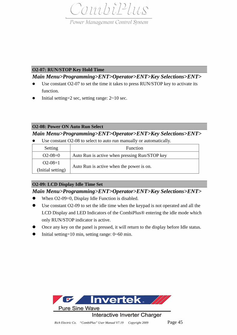
Rich Electric Co. “CombiPlus” User Manual V7.19 Copyright 2009 Page 45
O2-07: RUN/STOP Key Hold Time Main Menu>Programming>ENT>Operator>ENT>Key Selections>ENT>
Use constant O2-07 to set the time it takes to press RUN/STOP key to activate its function.
Initial setting=2 sec, setting range: 2~10 sec.
O2-08: Power ON Auto Run Select Main Menu>Programming>ENT>Operator>ENT>Key Selections>ENT>
Use constant O2-08 to select to auto run manually or automatically. Setting Function
O2-08=0 Auto Run is active when pressing Run/STOP key O2-08=1
(Initial setting) Auto Run is active when the power is on.
O2-09: LCD Display Idle Time Set Main Menu>Programming>ENT>Operator>ENT>Key Selections>ENT>
When O2-09=0, Display Idle Function is disabled. Use constant O2-09 to set the idle time when the keypad is not operated and all the
LCD Display and LED Indicators of the CombiPlus® entering the idle mode which only RUN/STOP indicator is active.
Once any key on the panel is pressed, it will return to the display before Idle status. Initial setting=10 min, setting range: 0~60 min.

Rich Electric Co. “CombiPlus” User Manual V7.19 Copyright 2009 Page 46
4.6 Main Menu :Operation “Monitor”
Main Menu: Operation
“Monitor” U1-01: AC IN Voltage Main Menu>Operation>ENT>Monitor>ENT>
Use U1-01 to monitor the current voltage value of AC IN power in unit of 0.1V.
U1-02: AC IN Current Main Menu>Operation>ENT>Monitor>ENT>
Use U1-02 to monitor the current value of AC IN power in unit of 0.1A. U1-03: AC OUT Voltage Main Menu>Operation>ENT>Monitor>ENT>
Use constant U1-03 to monitor AC OUT voltage value in unit of 0.1V.
U1-04: AC OUT Current Main Menu>Operation>ENT>Monitor>ENT>
Use constant U1-04 to monitor AC OUT current value in unit of 0.1A .
U1-05: Battery Voltage Main Menu>Operation>ENT>Monitor>ENT>
Use constant U1-05 to monitor the battery voltage in unit of 0.1V.
U1-06: Battery Ripple Voltage Main Menu>Operation>ENT>Monitor>ENT>
Use constant U1-06 to monitor the battery ripple voltage in unit of 0.1V.
U1-07: Battery Current Main Menu>Operation>ENT>Monitor>ENT>
Use constant U1-07 to monitor battery current value in unit of 0.1A.

Rich Electric Co. “CombiPlus” User Manual V7.19 Copyright 2009 Page 47
U1-08: Control Mode Main Menu>Operation>ENT>Monitor>ENT>
Use constant U1-08 to monitor the current control mode (MODE 1, MODE 2, MODE 3 or MODE 4)
U1-09: Operation Status Main Menu>Operation>ENT>Monitor>ENT>
There are 12 digits to account for each operation status. Please see NOTE 1 in Chapter 5 of the User Manual.
U1-10: Aux-Relay Status Main Menu>Operation>ENT>Monitor>ENT> Use constant U1-10 to monitor the ON/OFF status of 3 sets of Aux-Relay (RY1, RY2, RY3). Please see NOTE 2 in Chapter 5 of the User Manual. U1-11: Elapsed Time Main Menu>Operation>ENT>Monitor>ENT>
Use constant U1-11 to monitor the elapsed time after power ON (O2-03=0) or after RUN (O2-03=1) in unit of 1 hour.
U1-12: Battery Temperature Sensor Main Menu>Operation>ENT>Monitor>ENT>
Use constant U1-12 to monitor the temperature that has been detected by Battery Temperature Sensor (BTS-3) in unit of 1℃.
U1-13: CPU ID1 Main Menu>Operation>ENT>Monitor>ENT>
Use constant U1-13 to check the software version 1.

Rich Electric Co. “CombiPlus” User Manual V7.19 Copyright 2009 Page 48
U1-14: CPU ID2 Main Menu>Operation>ENT>Monitor>ENT>
Use constant U1-14 to check the software version 2. U1-15: Solar Charger Status Main Menu>Operation>ENT>Monitor>ENT>
Use constant U1-15 to monitor solar charger status after solar module is connected to the extension port (Port C).
U1-16: Solar Supply Current Main Menu>Operation>ENT>Monitor>ENT>
Use constant U1-16 to monitor the solar supply current value in unit of 0.1A. U1-17: Solar Supply Power Main Menu>Operation>ENT>Monitor>ENT>
Use constant U1-17 to monitor the solar supply power value in unit of 1W. U1-18: Solar Amp-Hours Main Menu>Operation>ENT>Monitor>ENT>
Use constant U1-18 to monitor solar Amp-Hours value in unit of 1AH. U1-19: Solar Total Amp-Hours Main Menu>Operation>ENT>Monitor>ENT>
Use constant U1-19 to monitor solar total Amp-Hours value in unit of 1AH. U1-35: External ATS Status
Main Menu> Operation>ENT> Monitor>ENT>
Use constant U1-35 to monitor the external ATS communication status. If it shows “COMM Fault”, the communication between ATS and the CombiPlus is not established.
When the AC power supply comes from the Master input of AC grid, this constant will show “Master Input” and the CombiPlus will switch to Mode 1 automatically.
When the AC power supply comes from the Slave input of AC generator, this constant will show “Slave Input” and the CombiPlus will switch to Mode 2 automatically.

Rich Electric Co. “CombiPlus” User Manual V7.19 Copyright 2009 Page 49
4.7 Main Menu : Operation “Fault Trace”
Main Menu: Operation
“Fault Trace” U2 Group (Fault Trace) U2-01: Current Fault Main Menu>Operation>ENT>Fault Trace>ENT>
Use constant U2-01 to monitor the current fault that results in “CombiPlus®” stopping operating.
U2-02: Last Fault Main Menu>Operation>ENT>Fault Trace>ENT>
Use constant U2-02 to monitor the last fault that has been recorded. U2-03: AC IN Voltage Main Menu>Operation>ENT>Fault Trace>ENT>
Use constant U2-03 to monitor the AC input voltage value in unit of 0.1V when the current fault occurs.
U2-04: AC IN Current Main Menu>Operation>ENT>Fault Trace>ENT>
Use constant U2-04 to monitor the AC input current value in unit of 0.1A when the current fault occurs.
U2-05: AC OUT Voltage Main Menu>Operation>ENT>Fault Trace>ENT>
Use constant U2-05 to monitor the AC output voltage value in unit of 0.1V when the current fault occurs.

Rich Electric Co. “CombiPlus” User Manual V7.19 Copyright 2009 Page 50
U2-06: AC OUT Current Main Menu>Operation>ENT>Fault Trace>ENT>
Use constant U2-06 to monitor the AC output current value in unit of 0.1A when the current fault occurs.
U2-07: Battery Voltage Main Menu>Operation>ENT>Fault Trace>ENT>
Use constant U2-07 to monitor the battery voltage value in unit of 0.1V when the current fault occurs.
U2-08: Battery Ripple Volt Main Menu>Operation>ENT>Fault Trace>ENT>
Use constant U2-08 to monitor the battery ripple voltage in unit of 0.1V when the current fault occurs.
U2-09: Battery Current Main Menu>Operation>ENT>Fault Trace>ENT>
Use constant U2-09 to monitor the battery current value in unit of 0.1A when the current fault occurs.
U2-10: Control Mode Main Menu>Operation>ENT>Fault Trace>ENT>
Use constant U2-10 to monitor what the control mode (MODE 1, MODE 2, MODE 3 or MODE 4) is when the current fault occurs.
U2-11: Operation Status Main Menu>Operation>ENT>Fault Trace>ENT>
Use constant U2-11 to monitor 12 digits which account for each operation status when the current fault occurs. Please see NOTE 1 in Chapter 8.
U2-12: Aux-Relay Status Main Menu>Operation>ENT>Fault Trace>ENT>
Use constant U2-12 to monitor the ON/OFF status of 3 sets of Aux-Relay (RY1, RY2, RY3) when the current fault occurs. Please see NOTE 2 in Chapter 8.
U2-13: Elapsed Time

Rich Electric Co. “CombiPlus” User Manual V7.19 Copyright 2009 Page 51
Main Menu>Operation>ENT>Fault Trace>ENT> Use constant U2-13 to monitor the elapsed time after power ON (O2-03=0) or after
RUN (O2-03=1) in unit of 1 hour when the current fault occurs. U2-14: Solar Charger Status Main Menu>Operation>ENT>Fault Trace>ENT>
Use constant U2-14 to monitor solar charger status when the current fault occurs. This constant is only visible when extension port is connected to solar module.
U2-15: Solar Charge Current Main Menu>Operation>ENT>Fault Trace>ENT>
Use constant U2-15 to monitor the solar charge current value in unit of 0.1A when the current fault occurs.
U2-16: Solar Supply Power Main Menu>Operation>ENT>Fault Trace>ENT>
Use constant U2-16 to monitor the solar supply power value in unit of 1W when the current fault occurs.
U2-17: Solar Amp-Hours Main Menu>Operation>ENT>Fault Trace>ENT>
Use constant U2-17 to monitor solar Amp-Hours value in unit of 1AH when the current fault occurs.
U2-18: Solar Total Amp-Hours Main Menu>Operation>ENT>Fault Trace>ENT>
Use constant U2-18 to monitor solar total Amp-Hours value in unit of 1AH when the current fault occurs.
U2-26: Battery Temperature Sensor Main Menu>Operation>ENT>Fault Trace>ENT>
Use constant U2-26 to monitor the current temperature that has been detected by Battery Temperature Sensor (BTS-3) in unit of 1℃ when the current fault occurs.
4.8 Main Menu : Operation “Fault History”

Rich Electric Co. “CombiPlus” User Manual V7.19 Copyright 2009 Page 52
Main Menu: Operation
“Fault History” U3 Group (Fault History) U3-01: Last Fault Main Menu>Operation>ENT>Fault History>ENT>
Use constant U3-01 to monitor the latest fault stored in the software.
U3-02: Fault Message 2 Main Menu>Operation>ENT>Fault History>ENT>
Use constant U3-02 to monitor the most recent second fault stored in the software.
U3-03: Fault Message 3 Main Menu>Operation>ENT>Fault History>ENT>
Use constant U3-03 to monitor the most recent third fault stored in the software.
U3-04: Fault Message 4 Main Menu>Operation>ENT>Fault History>ENT>
Use constant U3-04 to monitor the most recent fourth fault stored in the software.
U3-05: Elapsed Time 1 Main Menu>Operation>ENT>Fault History>ENT>
Use constant U3-05 to monitor the elapsed time before the latest fault occurs.

Rich Electric Co. “CombiPlus” User Manual V7.19 Copyright 2009 Page 53
U3-06: Elapsed Time 2 Main Menu>Operation>ENT>Fault History>ENT>
Use constant U3-06 to monitor the elapsed time before the most recent second fault occurs.
U3-07: Elapsed Time 3 Main Menu>Operation>ENT>Fault History>ENT>
Use constant U3-07 to monitor the elapsed time before the most recent third fault occurs.
U3-08: Elapsed Time 4 Main Menu>Operation>ENT>Fault History>ENT>
Use constant U3-08 to monitor the elapsed time before the most recent fourth fault occurs.
`

Rich Electric Co. “CombiPlus” User Manual V7.19 Copyright 2009 Page 54
Chapter 5 Mode Settings
5.1 Four Control Modes Applications
MODE 1:
AC Power as has Priority to Support the AC Load.
MODE 2:
AC Generator has Priority to Support the AC Load with Dynamic Power Shifting.
MODE 3:
Renewable Energy has Priority to Charge the batteries. The Combi Inverter has Priority to Support the AC load with AC Power Support.
MODE 4:
Renewable Energy has Priority to Charge the batteries with AC Charger Support. The Combi Inverter has Priority to Support the AC load with AC Power Support.

Rich Electric Co. “CombiPlus” User Manual V7.19 Copyright 2009 Page 55
MODE 1:
AC Power as has Priority to Support the AC Load.
(Example of CP-3000-242) When CombiPlus enters to MODE 1, B2-09 (AC IN DynaCur Limit)=0 (Disable) and the value of B2-18 (MODE1: ACINCurrent Lmt) will be loaded to B2-05.
INVERTER Mode: When AC IN=0 A, AC OUT load is completely supplied by INVERTER. It goes to the
inverter mode.
Battery
Grid,Shore,Generator Power Load
ATS OFFAC IN AC OUT
5A
5A
0A
75A

Rich Electric Co. “CombiPlus” User Manual V7.19 Copyright 2009 Page 56
Mode 1
Interactive Power Sharing Mode (a) In this example:
All AC loads are off, with the “CombiPlus” constant B2-05=5A (AC IN Current Limit), The AC CHARGER will not take more than 5A with limits to battery charge current to 75A.
Battery
Shore Power Max 5A Load
ATS ONAC IN AC OUT
5A
5A
0A
75A
5A
B2-05=5A

Rich Electric Co. “CombiPlus” User Manual V7.19 Copyright 2009 Page 57
Mode 1
Interactive Power Sharing Mode (b) Now some small loads are switched on and load increase to 3A. Only 5-3=2A is left to
Charge the batteries and charge current is reduced to about 30A. ※ Note: Shore current is automatically limited to 5A and the AC input circuit Breaker will not trip!
Battery
Shore Power Max 5A Load
ATS ONAC IN AC OUT
5A
2A
30A
5A
B2-05=5A
3A

Rich Electric Co. “CombiPlus” User Manual V7.19 Copyright 2009 Page 58
Mode 1
Interactive Power Sharing Mode (c) The load is switched on and current consumption increase to 5A. Nothing is left to charge
the battery. The charge current is automatically reduced to 0A, and the AC input circuit breaker does
not trip!
Battery
Shore Power Max 5A Load
ATS ONAC IN AC OUT
5A
0A
5A
B2-05=5A
5A
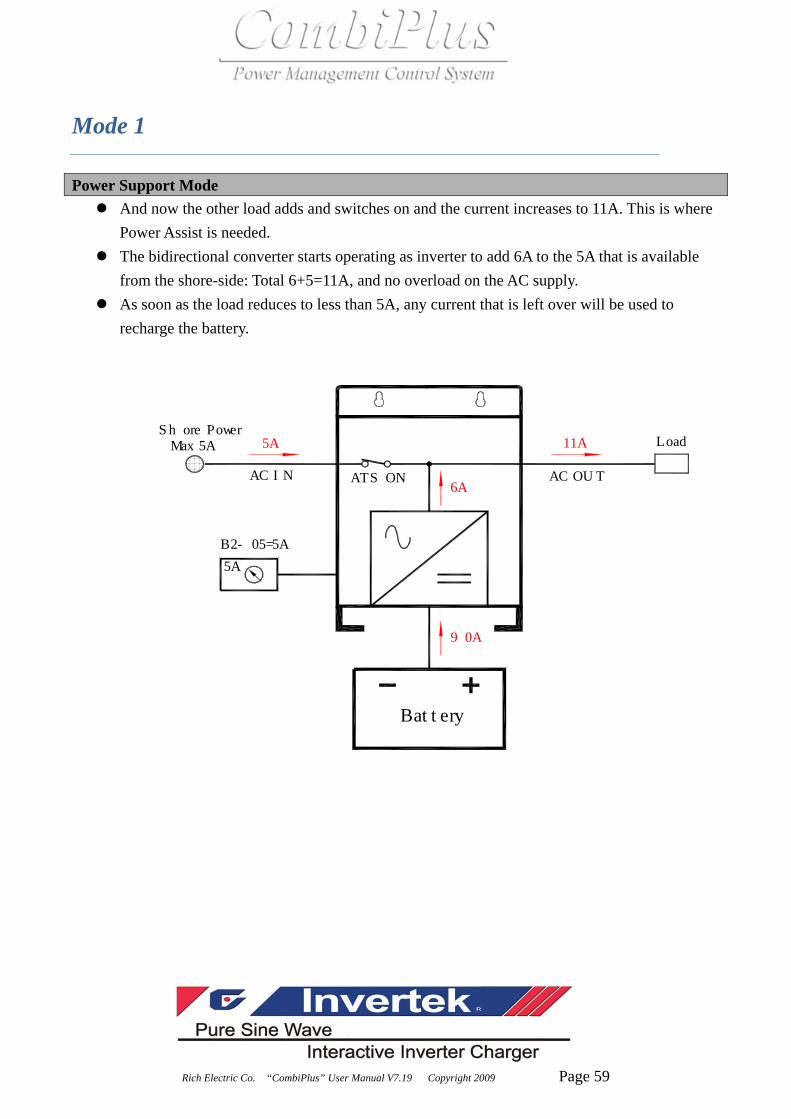
Rich Electric Co. “CombiPlus” User Manual V7.19 Copyright 2009 Page 59
Mode 1
Power Support Mode And now the other load adds and switches on and the current increases to 11A. This is where
Power Assist is needed. The bidirectional converter starts operating as inverter to add 6A to the 5A that is available
from the shore-side: Total 6+5=11A, and no overload on the AC supply. As soon as the load reduces to less than 5A, any current that is left over will be used to
recharge the battery.
Battery
Shore Power Max 5A Load
ATS ONAC IN AC OUT
5A
6A
5A
B2-05=5A
11A
90A

Rich Electric Co. “CombiPlus” User Manual V7.19 Copyright 2009 Page 60
MODE 2:
AC Generator has Priority to Support the AC Load
with Dynamic Power Shifting.
When CombiPlus enters to MODE 2, B2-09(AC IN DynaCur Limit)=1 (Enable) and the value of B2-19 (MODE 2: ACINCurrent Lmt) will be loaded to B2-05.
INVERTER Mode: When AC IN=0 A, AC OUT load is completely supplied by INVERTER. It goes to the
inverter mode.
Battery
Grid,Shore,Generator Power Load
ATS OFFAC IN AC OUT
5A
5A
0A
75A

Rich Electric Co. “CombiPlus” User Manual V7.19 Copyright 2009 Page 61
Mode 2
Interactive Power Sharing Mode (a) In this example:
All AC loads are off, with the “CombiPlus” constant B2-05=5A (AC IN Current Limit), The AC CHARGER will not take more than 5A with limits to battery charge current to 75A.
Battery
Shore Power Max 5A Load
ATS ONAC IN AC OUT
5A
5A
0A
75A
5A
B2-05=5A

Rich Electric Co. “CombiPlus” User Manual V7.19 Copyright 2009 Page 62
Mode 2
Interactive Power Sharing Mode (b) Now some small loads are switched on and load increase to 3A. Only 5-3=2A is left to
Charge the batteries and charge current is reduced to about 30A. ※ Note: Shore current is automatically limited to 5A and the AC input circuit Breaker will not trip!
Battery
Shore Power Max 5A Load
ATS ONAC IN AC OUT
5A
2A
30A
5A
B2-05=5A
3A

Rich Electric Co. “CombiPlus” User Manual V7.19 Copyright 2009 Page 63
Mode 2
Interactive Power Sharing Mode (c) The load is switched on and current consumption increase to 5A. Nothing is left to charge
the battery. The charge current is automatically reduced to 0A, and the AC input circuit breaker does
not trip!
Battery
Shore Power Max 5A Load
ATS ONAC IN AC OUT
5A
0A
5A
B2-05=5A
5A

Rich Electric Co. “CombiPlus” User Manual V7.19 Copyright 2009 Page 64
5.2 Green Power Smart Feature
Green Power Smart Feature
Renewable Energy MODES 3 & 4
Green Power Smart Feature: Green Power Smart Modes 3 and 4 are designed to conserve energy, whether you are connected to the mains grid power or for use in a standalone power system where there is no mains available. The Green Power Smart feature uses renewable energy such as solar, wind and hydro generation to recharge the batteries and will only connect to the mains grid or start the generator as a last resort. Even if the Combi unit cannot support the load, it will automatically connect to the grid or start the generator to help supply continuous power until the load has decreased. This ingenious smart power feature will make sure your batteries always get the charge they require, helping them to last longer in demanding installations.

Rich Electric Co. “CombiPlus” User Manual V7.19 Copyright 2009 Page 65
How does Green Power Smart work?
If the system is installed into a typical home with an array of solar panels that produce an average of 7kw per day, this renewable energy is used to re-charge the batteries and power appliances. During the night there is no “free energy” being produced from the solar panels; the appliances are powered from the storage batteries. If the daily energy used to power the fridge, lights, TV and other appliances total 10kw for the day, the Combi unit will automatically know the batteries need to be topped up or recharged from another source. The Combi unit will automatically connect to the mains grid or start a backup generator to replenish this charge. If the CombiPlus is installed in a boat or where there is no mains power available, a signal can be sent to the generator to automatically start and stop it in the same way as when the system is Connected to the grid power. The generator can be programmed to only operate for minimum run time to avoid intermittent starting of the generator. This ingenious power management will avoid the generator running longer than necessary taking the guess work out of when your generator should be on or off, making for a smart, more refined, fully automated power supply.
MODE 3:
Renewable Energy has Priority to Charge the batteries. The Combi Inverter has Priority to Support the AC load with AC Power Support
MODE 4:
Renewable Energy has Priority to Charge the batteries with AC Charger Support. The Combi Inverter has Priority to Support the AC load with AC Power Support.

Rich Electric Co. “CombiPlus” User Manual V7.19 Copyright 2009 Page 66
MODE 3:
Renewable Energy has Priority to Charge the batteries.
The Combi Inverter has Priority to Support the
AC load with AC Power Support.
When CombiPlus enters to MODE 3, B2-09(AC IN DynaCur Limit)=0 (Disable) and the value of B2-20 (MODE3: ACINCurrent Lmt) will be loaded to B2-05.
INVERTER Mode: When the battery voltage is not lower than (B2-14) voltage value, inverter mode takes
priority to supply voltage to AC OUT for load consumption. (INVERTER ON+ ATS OFF + AC CHARGER OFF)
Battery
Shore Power Ready Load
ATS OFFAC IN AC OUT3A
5A
B2-05=5A
3A
45A
SolarCharger
Solar Panel
or

Rich Electric Co. “CombiPlus” User Manual V7.19 Copyright 2009 Page 67
Mode 3
Interactive Power Sharing Mode When AC IN power is ready, INVERTER is active and battery voltage is lower than B2-14
voltage value and longer than the second time set in B2-15, ATS will be switched on to ensure AC OUT to continuously supply the load. At the moment, AC OUT will be supplied by AC IN power.
In Mode 3 The AC CHARGER will remain OFF. The batteries will only be recharged by renewable energy input such as solar, wind generator or DC generator charger.
The difference between MODE 3 and MODE 4 is that in MODE 3, when AC IN power is ready, AC CHARGER is off and the battery is charged only by other renewable energy sources. This is why MODE 3 is called Green Power as Priority Support Mode (INVERTER OFF+ ATS ON + AC CHARGER OFF)
Battery
Shore Power Load
ATS ONAC IN AC OUT
5A
B2-05=5A
3A
SolarCharger
Solar Panel
or
3A
AC Charger OFF

Rich Electric Co. “CombiPlus” User Manual V7.19 Copyright 2009 Page 68
Mode 3
Power Support Mode And now the other load adds and the current increases to 11A. This is where Power Support
function is needed! (ATS ON + AC CHARGER OFF + INVERTER ON + Power Support Mode ON)
As soon as the load reduces to less than 5A, power assist function stops.
Battery
Shore Power Load
ATS ONAC IN AC OUT
5A
B2-05=5A
11A
SolarCharger
Solar Panel
or
5A
6A
90A

Rich Electric Co. “CombiPlus” User Manual V7.19 Copyright 2009 Page 69
Mode 3
4. “INVERTER Mode” Repeat When the battery is recharged by other renewable energy source, battery voltage is higher
than B2-14 voltage value and longer than second time set in B2-15, inverter mode takes priority to supply voltage to AC OUT again for load consumption.
Battery
Shore Power Ready Load
ATS OFFAC IN AC OUT
3A
SolarCharger
Solar Panel
or
3A
45A
0A

Rich Electric Co. “CombiPlus” User Manual V7.19 Copyright 2009 Page 70
MODE 4:
Renewable Energy has Priority to Charge the batteries
with AC Charger Support. The Combi Inverter has Priority
to Support the AC load with AC Power Support.
When CombiPlus enters to MODE 4, B2-09(AC IN DynaCur Limit)=0 (Disable) and the value of B2-19 (MODE4: ACINCurrent Lmt)will be loaded to B2-05.
1. INVERTER Mode: When the battery voltage is not lower than (B2-10) voltage value, inverter mode takes
priority to supply voltage to AC OUT for load consumption. (INVERTER ON+ ATS OFF + AC CHARGER OFF)
Battery
Shore Power Ready Load
ATS OFFAC IN AC OUT3A
5A
B2-05=5A
3A
45A
SolarCharger
Solar Panel
or
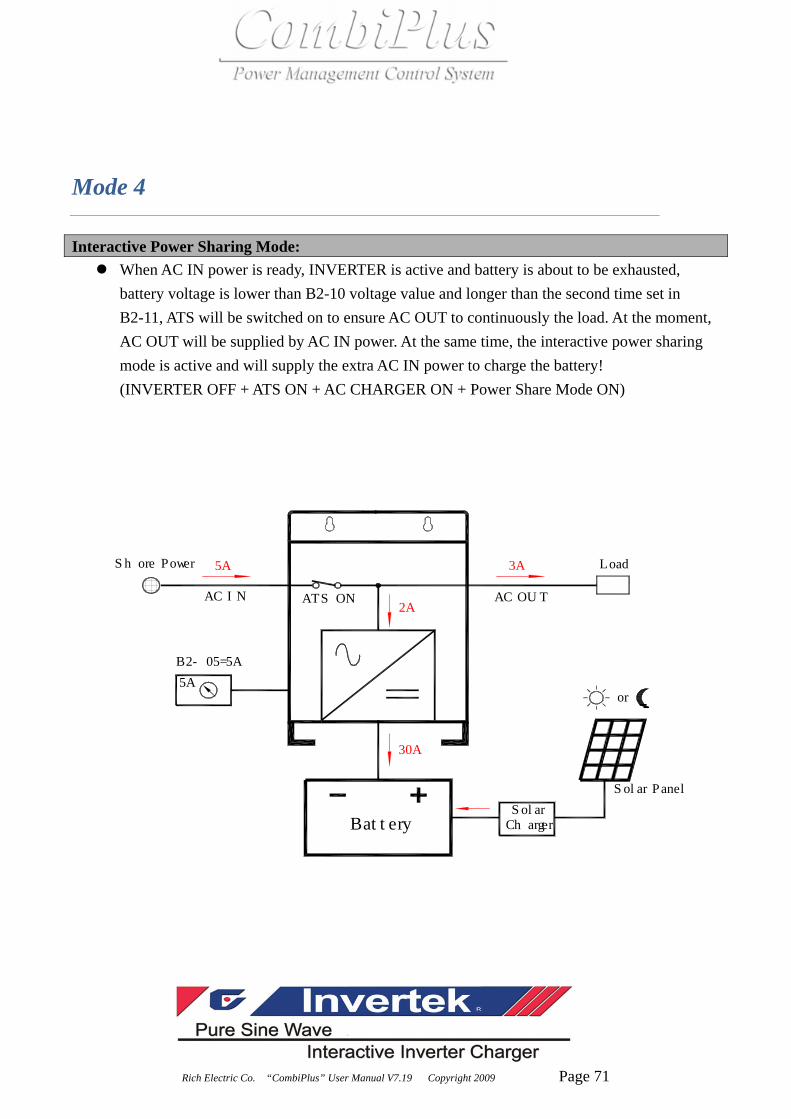
Rich Electric Co. “CombiPlus” User Manual V7.19 Copyright 2009 Page 71
Mode 4
Interactive Power Sharing Mode: When AC IN power is ready, INVERTER is active and battery is about to be exhausted,
battery voltage is lower than B2-10 voltage value and longer than the second time set in B2-11, ATS will be switched on to ensure AC OUT to continuously the load. At the moment, AC OUT will be supplied by AC IN power. At the same time, the interactive power sharing mode is active and will supply the extra AC IN power to charge the battery! (INVERTER OFF + ATS ON + AC CHARGER ON + Power Share Mode ON)
Battery
Shore Power Load
ATS ONAC IN AC OUT2A
5A
B2-05=5A
3A
30A
SolarCharger
Solar Panel
or
5A

Rich Electric Co. “CombiPlus” User Manual V7.19 Copyright 2009 Page 72
Mode 4
Power Support Mode And now the other load adds and the current increases to 11A. This is where Power Support
function is needed! (ATS ON + AC CHARGER OFF + INVERTER ON + Power Support Mode ON)
As soon as the load reduces to less than 5A, any current that is left over will be used to recharge the battery.
Battery
Shore Power Load
ATS ONAC IN AC OUT6A
5A
B2-05=5A
11A
90A
SolarCharger
Solar Panel
or
5A

Rich Electric Co. “CombiPlus” User Manual V7.19 Copyright 2009 Page 73
Mode 4
“INVERTER Mode” Repeat When the battery voltage is higher than B2-12 voltage value and longer than second time set
in B2-15, inverter mode takes priority to supply voltage to AC OUT again for load consumption.
Battery
Shore Power Ready Load
ATS OFFAC IN AC OUT3A
5A
B2-05=5A
3A
45A
SolarCharger
Solar Panel
or

Rich Electric Co. “CombiPlus” User Manual V7.19 Copyright 2009 Page 74
Chapter 6 Programming
Note: Settings should only be changed by a qualified engineer. Carefully read the user manual before any change is made.
Programming Constants A Group (Initialize): A1 Group (Initialize) A1-01: Access level
Use constant A1-01 to select the user constant access level. This level determines which user constants can be changed and displayed.
Setting Function
A1-01=0
This setting allows the “operation” and “initialize” to be changed or displayed. Use this setting to prevent user constant settings from being changed.
A1-01=1 (Initial setting)
This setting allows all user constants to be changed or displayed.

Rich Electric Co. “CombiPlus” User Manual V7.19 Copyright 2009 Page 75
A1-02: Select Language
Use constant A1-02 to select the language displayed by the CombiPlus®. A value of 0 set English and values of others set other language.
This user constant is not returned to factory setting when constants are initialized. It must be manually reset to factory setting. Setting Function
A1-02=0 (Initial setting)
English language
A1-02=1 Reserved, under development A1-02=2 Reserved, under development A1-02=3 Reserved, under development A1-02=4 Reserved, under development A1-02=5 Reserved, under development A1-02=6 Reserved, under development
A1-03: Init Parameters
Use constant A1-03 to initialize the user constants. When initialized, the user constants will return to their factory preset values. You should
normally record the setting of any constants that are changed from factory presets. Setting Function
A1-03=0 (Initial setting)
Returns to initialize Display without initializing any user constants.
A1-03=1 Initializes the user constants to factory settings.

Rich Electric Co. “CombiPlus” User Manual V7.19 Copyright 2009 Page 76
A1-04: Init Password 1
This constant is reserved for the factory to test and set the functions. Users are not allowed to set this constant.
Lock the constants setting (A1-01=1) 1. Finish setting all the programmable parameters to desired values. 2. Change A1-01=0 (Operation only), factory setting is A1-01=1 (Constants set). 3. Go to A1-04 and press RUN/STOP key and UP key at the same time till A1-05 parameter occurs. 4. Enter the desired password (max. 4 digits) 5. Press UP key to leave A1-05
Above procedure completes locking the constants setting and no more programming selection would appear. A1-01 would only display 0 (Operation only) and would not display 1 (Constants set).
Unlock the constants setting 1. Enter the password in A1-04 to be exactly the same as the one earlier set in A1-05 2. When the password in A1-04 matches the one earlier set in A1-05, the unlocking is completed.
A1-01=1 (Constants set) would appear again for programming.

Rich Electric Co. “CombiPlus” User Manual V7.19 Copyright 2009 Page 77
B Group (General): B1 Group (Output Frequency) B1-01: Output frequency Main Menu>Programming>ENT>General>ENT>Output Frequency>ENT
B1-01 is used to set the output frequency at INVERTER AC output Setting Function
B1-01=0 (Initial setting)
50Hz at INVERTER AC output
B1-01=1 60Hz at INVERTER AC output
B2-08: AC IN Frequency Range Setting Function
When B1-01=0: Acceptable AC input frequency is 50Hz ±5Hz (45~55Hz)
B2-08=0 When B1-01=1: Acceptable AC input frequency is 60Hz ±5Hz (55~65Hz)
B2-08=1 (Initial setting)
Accept wide AC input frequency range between 45~65Hz

Rich Electric Co. “CombiPlus” User Manual V7.19 Copyright 2009 Page 78
B2 Group (Auto Transfer Switch) B2-01: AC IN Low Disconnect Main Menu>Programming>ENT>General>ENT>Auto transfer Switch>ENT
Use constant B2-01 to determine the AC IN voltage below which level the ATS (Auto Transfer Switch) will switch off.
This voltage level will always lie below the AC IN Low Connect (B2-02) level. In fact, changing this level will also change the AC IN Low Connect (B2-02) level.
B2-02: AC IN Low Connect Main Menu>Programming>ENT>General>ENT>Auto transfer Switch>ENT
This setting forms a pair with AC IN Low Disconnect (B2-01). With this setting, one determines the AC IN low voltage at which level the ATS will switch on. This should lie above AC IN Low Disconnect (B2-01) level to prevent continuous switching off the ATS when the voltage is fluctuating around the level. The parameter which is changed is the difference between AC IN Low Disconnect (B2-01) and AC IN Low Connect (B2-02).
The result of this is that when changing B2-01 level, this level (B2-02) also changes. ※ Note: B2-02 can be ignored for a short time when AC IN Waveform Check (B2-06) is
Disabled (B2-06=0) When the AC IN voltage drops due to the increasing charge current, the AC CHARGER will
take care that the voltage does not drop below this level. B2-02=B2-01+offset voltage
For example: CP-1500-122, when B2-01=180V, B2-02=187V, offset voltage=7V (187-180), B2-02 will automatically go to 197V(190+7) after B2-01 is changed to 190V.
B2-03: AC IN High Connect Main Menu>Programming>ENT>General>ENT>Auto transfer Switch>ENT
This setting forms a pair with AC IN High Disconnect (B2-04). With this setting, one determines the AC IN high voltage at which level the ATS will switch on. This should lie below the AC IN High Disconnect (B2-04) level to prevent continuous switching of the ATS when the voltage is fluctuating around that level.
In fact, the parameter which is changed is the difference between AC IN High Disconnect (B2-04) and AC IN High Connect (B2-03).
The result of this is that when changing B2-04 level, this level (B2-03) also changes. B2-03=B2-04–offset voltage For example: CP-1500-122, when B2-03=265V, B2-04=270V,
offset voltage=5V (270-265), B2-03 will automatically go to 255V(260–5) after B2-04 is changed to 260V.

Rich Electric Co. “CombiPlus” User Manual V7.19 Copyright 2009 Page 79
B2-04: AC IN High Disconnect Main Menu>Programming>ENT>General>ENT>Auto transfer Switch>ENT
Use constant B2-04 to determine the AC IN voltage above which level the ATS will switch off. This voltage level will always lie above the AC IN High Connect (B2-03) level. In fact,
changing this level will also change the AC IN High Connect (B2-03) level. B2-05: Interactive Power Sharing “AC IN Current Limit” Main Menu>Programming>ENT>General>ENT>Auto transfer Switch>ENT
Use constant B2-05 to set the set the specific maximum AC input current. This value is very important for both battery charger and inverter output power Support.
When using constant B2-05, the values determine the actual AC current limit. ※Note: With Power Support enabled, there is a minimum value for the AC input current limit.
Please see the note at Power Support (page 71). B2-06: AC IN Waveform Check Main Menu>Programming>ENT>General>ENT>Auto transfer Switch>ENT
Use constant B2-06 to enable/disable the fast detection of input voltage wave shape. Setting Function
B2-06=0 (Ignore)
By disabling AC IN waveform check, AC IN Low Disconnect (B2-01) is ignored. When the load current is higher 1.5 times than AC In Current Limit (B2-05), this is used to prevent unnecessary switching to INVERTER due to voltage drop when a high load is connected.
B2-06=1 (Initial setting)
(Active)
This detection checks the wave shape, if it is not sinusoidal within certain limits, the AC input voltage is rejected.
However, certain generator or very weak mains supply have an ill shaped sinusoidal output especially when the load suddenly changes. The fast detection will detect a failure in such a case.
This will result in a slightly longer transfer time.

Rich Electric Co. “CombiPlus” User Manual V7.19 Copyright 2009 Page 80
B2-07: Ground Relay (MEN) Main Menu>Programming>ENT>General>ENT>Auto transfer Switch>ENT
Used to enable/disable the internal ground relay functionality. The ground relay is useful when an earth-leakage circuit-breaker is part of the installation.
When ATS (Auto Transfer Switch) is open (INVERTER mode), the Neutral of the inverter is connected to “G” terminal.
When ATS closes (AC IN is transferred to AC OUT), the Neutral is first disconnected from “G” terminal. Setting Function
B2-07=0 The internal ground relay is open with “G” terminal. B2-07=1
(Initial setting) The internal ground relay is closed with “G” terminal.
B2-08: AC IN Frequency Range Main Menu>Programming>ENT>General>ENT>Auto transfer Switch>ENT
B2-08: is used to set the AC IN Frequency Range Setting Function
When B1-01=0: Acceptable AC input frequency is 50Hz ±5Hz (45~55Hz)
B2-08=0 When B1-01=1: Acceptable AC input frequency is 60Hz ±5Hz (55~65Hz)
B2-08=1 (Initial setting)
Accept wide AC input frequency range between 45~65Hz

Rich Electric Co. “CombiPlus” User Manual V7.19 Copyright 2009 Page 81
B2-09: AC IN Dynamic Power Shifting Main Menu>Programming>ENT>General>ENT>Auto transfer Switch>ENT
This setting is an expansion of the AC IN Current Limit (B2-05) mechanism. Setting Function
B2-09=0 (Initial setting)
The AC current limit is specified by the AC IN Current Limit (B2-05) setting
B2-09=1
The effective AC input current limit depends on the load history. When the load is lower than the AC IN Current Limit (B2-05), the effective AC input current limit is also lower but slightly above the load.
When the load increase, the effective current limit also increases with a delay. The thought behind this is that when a generator is running at a low load, it can’t switch to full load immediately and it needs some time to increase the power.
An example: We have a 2KVA generator.
We adjust the AC IN Current Limit (B2-05) setting to 8A and we enable Power Support (C1-05=1). We have no load connected and the batteries are fully charged. Therefore, no current from generator is drawn.
At this moment, we connect a load of 7A to the CombiPlus® with this setting (B2-09) disabled, the CombiPlus® would not react because the load is below the AC IN Current Limit (B2-05) setting. The result is that the full load is connected to generator which will drop in voltage because it can’t deliver that current instantly which could result in switching to INVERTER.
If however we had this setting (Dynamic Power Shifting) enabled, the effective AC input current limit would be far lower than 8A because the load was zero. So connecting a load of 7A will result in CombiPlus® starting to power Support and no voltage drop is being examined on the AC OUT. The generator starts to supply the load and the effective AC input current limit will increase to 8A slowly. At the moment, the CombiPlus® will stop Power Support and the full load is on the generator.
This is powerful option in combination with Power Support but even without Power Support, it can prevent unnecessary switching to INVERTER because the charge current will reduce when AC input current becomes higher than the effective AC input current limit.

Rich Electric Co. “CombiPlus” User Manual V7.19 Copyright 2009 Page 82
B2-10: MODE4: Bat Lo?V ATS ON B2-11: MODE4: Bat Lo?S ATS ON B2-12: MODE4: Bat Hi?V ATSOFF B2-13: MODE4: Bat Hi?S ATSOFF B2-14: MODE3: Bat Lo?V ATS ON B2-15: MODE3: Bat Lo?S ATS ON B2-16: MODE3: Bat Hi?V ATSOFF B2-17: MODE3: Bat Lo?S ATSOFF
B2-10~B2-13 are used to set the condition of ATS to be ON/OFF in MODE4 B2-14~B2-17 are used to set the condition of ATS to be ON/OFF in MODE3
When CombiPlus® is in either MODE4 or MODE3, INVERTER mode takes priority to supply voltage to AC OUT for load consumption. When AC IN power is ready, INVERTER is active and battery is about to be exhausted, ATS will be switched on to ensure AC OUT to continuously supply the load. At the moment, AC OUT will be supplied by AC IN power. At the same time, the battery can be charged by other renewable energy such as solar charger, wind charger or DC generator charger (MODE3) which is normally the solar house application in no need of AC CHARGER.
MODE3: B2-14 and B2-15 are used to set ATS to be “ON” when the battery voltage is lower than B2-14 voltage value and longer than the second time set in B2-15 in MODE3.
(ATS ON+INVERTER OFF+AC CHARGER ON) MODE 3: B2-16 and B2-17 are used to set ATS to be “OFF” when the battery voltage is higher
than B2-16 voltage value and longer than the second time set in B2-17 in MODE3. (INVERTER ON+ATS OFF+ AC CHARGER OFF)
In (MODE 4) The battery can be charged by AC IN (AC CHARGER) or other renewable
energy such as solar charger, wind charger or DC generator charger which is normally the application requesting both AC charging and DC charging. When charging battery slowly reaches to certain level, this means battery will be fully charged soon and the ATS will be switched off for INVERTER to take over the ongoing supply to AC OUT for load.
MODE 4: B2-10 and B2-11 are used to set ATS to be “ON” when the battery voltage is lower than B2-10 voltage value and longer than the second time set in B2-11 in MODE4.
(INVERTER OFF+ATS ON+AC CHARGER ON) MODE 4: B2-12 and B2-13 are used to set ATS to be “OFF” when the battery voltage is higher
than B2-12 voltage value and longer than the second time set in B2-13 in MODE4. (INVERTER ON+ATS OFF+AC CHARGER OFF)

Rich Electric Co. “CombiPlus” User Manual V7.19 Copyright 2009 Page 83
B2-18: MODE1: ACIN Current Lmt Main Menu>Programming>ENT>General>ENT>Auto transfer Switch>ENT
Use constant B2-18 to set the set the specific maximum AC input current in MODE 1. This value is very important for both battery charger and inverter output power Support.
When using constant B2-18, the values determine the actual AC current limit. B2-19: MODE2: ACIN Current Lmt Main Menu>Programming>ENT>General>ENT>Auto transfer Switch>ENT
Use constant B2-19 to set the set the specific maximum AC input current in MODE 2. This value is very important for both battery charger and inverter output power Support.
When using constant B2-19, the values determine the actual AC current limit. B2-20: MODE3: ACIN Current Lmt Main Menu>Programming>ENT>General>ENT>Auto transfer Switch>ENT
Use constant B2-20 to set the set the specific maximum AC input current in MODE 3. This value is very important for both battery charger and inverter output power Support.
When using constant B2-20, the values determine the actual AC current limit. B2-21: MODE4: ACIN Current Lmt Main Menu>Programming>ENT>General>ENT>Auto transfer Switch>ENT
Use constant B2-21 to set the set the specific maximum AC input current in MODE 4. This value is very important for both battery charger and inverter output power Support.
When using constant B2-21, the values determine the actual AC current limit. B2-29: External ATS Select
Main Menu> Programming>ENT>General>ENT>Auto transfer Switch>
ENT Constant B2-29 is used to select to enable or disable the external ATS for the AC power supply
control selection.

Rich Electric Co. “CombiPlus” User Manual V7.19 Copyright 2009 Page 84
B3 Group (Parallel System) B3-01: Number of Slaves Main Menu>Programming>ENT>General>ENT>Parallel System>ENT
A parallel system is built with 1 master and up to 4 slaves with this setting, one can specify the number of slaves in system. This setting has only to be done in the master. It is not required to specify the number of slaves. The system will work just fine without this setting being specified.
This setting is added for convenience of the end-user when the AC IN power is larger than the total of B2-05* the number of the CombiPlus® (Master + Slaves) when B3-01=0. The only effect of this setting is on the scaling of AC IN Current Limit (B2-05). If B3-01=0, one must divide the available AC current by the number of CombiPlus® (Master + Slaves) and set the limit accordingly. So an example of setting the B2-05=10A in a parallel system with 3 CombiPlus® would result in a limit of 3*10A=30A
Please Note: If however in this system the number of slaves is set 2 (B3-01=2), then the division is done internally and setting the AC IN Current Limit to 10A (B2-05=10) will result in 10A for the whole system and shared by the Master and Slaves. This system is often applied when the AC IN power is limited such as the generator of limited small capacity.
B4 Group (2-3 Phase) B4-01: 2-3 Phase Connection Main Menu>Programming>ENT>General>ENT>2-3 Phase>ENT
All the CombiPlus® in a multi-phase system must have 2-3 phase enabled. Use this setting to perform this.
If more CombiPlus® per phase are connected in parallel, then only the masters of parallel system must have 2-3 phase enabled. Setting Function
B4-01=0 (Initial setting)
2-3 Phase connection disabled.
B4-01=1 2-3 Phase connection enabled.

Rich Electric Co. “CombiPlus” User Manual V7.19 Copyright 2009 Page 85
B4-02: 2-3 Phase Master Main Menu>Programming>ENT>General>ENT>2-3 Phase>ENT
In a multi-phase system, there is always one (and only one) master. The CombiPlus® for other phases are called followers.
Use this setting to designate one of the CombiPlus® is master. If this parameter is set (B4-02=0), the CombiPlus® is a follower. Setting Function
B4-02=0 (Initial setting)
2-3 Phase connection system is called Follower
B4-02=1 2-3 Phase connection system is called Master B4-03: 2-3 Phase Type Main Menu>Programming>ENT>General>ENT>2-3 Phase>ENT
Use constant B4-03 to determine the kind of multi-phase required. Setting Function
B4-03=0 (Initial setting)
3 Phase type: Three CombiPlus® are required. Output is 3-phase with 120°phase shift.
B4-03=1 Split Phase 180°Type: Two CombiPlus® are required. Output is 2-phase with phase 180°shift
B4-03=2
Two Leg 3 Phase 120°Type: Two CombiPlus® are required. Output is 2-phase of a normal 3-phase system so two phases with 120°phase shift.

Rich Electric Co. “CombiPlus” User Manual V7.19 Copyright 2009 Page 86
C Group (INVERTER): C1 Group (INVERTER) C1-01: INVERTER Output Voltage Main Menu>Programming>ENT>Inverter>ENT
Use constant C1-01 to change the RMS output voltage of the INVERTER. C1-02: Bat Low ?V Shut-down Main Menu>Programming>ENT>Inverter>ENT
With this setting, one can determine the battery voltage at which level the INVERTER will switch off. This can be useful to prevent drawing too much current from an exhausted battery.
This voltage level will always lie below the Bat Low ? V Restart (C1-03) level. In fact, changing this level will also change the Bat Low ? V Restart (C1-03) level.
C1-03=C1-02+offset voltage For example: CP-1500-122, when C1-02=9.3V, C1-03=10.9V, offset voltage=1.6V (10.9-9.3), C1-03 will automatically go to 11.6V(10.0+1.6) after C1-02 is changed to 10.0V.
C1-03: Battery Low ? V Restart Main Menu>Programming>ENT>Inverter>ENT
This setting forms a pair with Bat Low ? V Shut-down (C1-02). With this setting, one determines the battery voltage at which level the INVERTER will switch on.
In fact, the parameter which is changed is the difference between Bat Low ? V Shut-down (C1-02) and Bat Low ? V Restart (C1-03). The result of this is that when changing the Bat Low ? V Shut-down (C1-02) level, this level also changes.
C1-04: Power Saving Select Main Menu>Programming>ENT>Inverter>ENT
When there is no AC load connected to the CombiPlus, set C1-04=1 (Initial setting) to active the power saving function by reducing the AC output voltage to be 144V for 230V model and to be 72 for 110V model.
Setting C1-04=0 can disable the auto power saving and the output voltage would be Continuously supplied to the AC Output even when there is no load connected.

Rich Electric Co. “CombiPlus” User Manual V7.19 Copyright 2009 Page 87
C1-05: Power Support Select Main Menu>Programming>ENT>Inverter>ENT
Using this constant C1-05, the Power Support feature can be enabled or disabled. Use Power Support to prevent an external circuit breaker to trip when the load on the CombiPlus® is too high.
If the load exceeds the AC IN Current Limit (B2-05), the CombiPlus® will start inverting and will provide the extra current needed.
※ Note: When Power Support is enabled. C1-05=1 (Initial setting), there is a minimum AC input current limit of approximate 2-3 Amps. Setting a lower limit (B2-05) than this minimum value will result in the minimum limit. (Note: In a parallel system, this limits per CombiPlus®!
Setting Function C1-05=0 Power Support Function is disabled. C1-05=1
(Initial setting) Power Support Function is enabled.
C1-06: Power Support Level Main Menu>Programming>ENT>Inverter>ENT
This setting is a special setting for power Support mode when the CombiPlus® is charging and due to a sudden load, the AC IN current exceeds the AC IN Current Limit (B2-05), the CombiPlus® will switch to power Support mode (when C1-05=1)
At that moment, the current need is unknown. The CombiPlus® makes an assumption of the magnitude of this current. This assumption is equal to AC IN Current Limit (B2-05) multiplied by this Power Support Level (C1-06). The default factor is two.
This will prevent the circuit breaker from tripping because current provided by the INVERTER minus the current drawn by the load is always lower than the rating of the circuit breaker. This happens, of course, when the AC IN Current Limit (B2-05) is correctly adjusted to the circuit breaker.
If for instance in a generator application, the circuit breaker has a higher value than the AC IN Current Limit (B2-05) (Normal load of generator is lower than maximum peak load) and one knows that the load which is switched on always draws a certain current, one can consider to increase this factor (C1-06) to achieve better results with sudden load changes.

Rich Electric Co. “CombiPlus” User Manual V7.19 Copyright 2009 Page 88
Battery Charging
Note: Settings should only be changed by a qualified engineer. Do not use non-rechargeable batteries. Batteries should be placed in a dry and well-ventilated area during charging.
The product default settings are for charging gel batteries. For the recommended battery voltage initial settings, see D1 (Charger) Group parameters

Rich Electric Co. “CombiPlus” User Manual V7.19 Copyright 2009 Page 89
D Group (AC CHARGER): D1 Group (Charger) D1-02: Battery Charging Curve Main Menu>Programming>ENT>Charger>ENT
Setting Function D1-02=1 Fixed D1-02=2 Adaptive D1-02=3
(Initial setting) Adaptive + Battery safe
The Fixed (D1-02=1) charge curve will have a faxed Absorption Time (D1-06). The Adaptive (D1-02=2) and Adaptive + Battery safe (D1-02=3) curve derive the Absorption
time from the Bulk time. The maximum Absorption time of these charge curves is determined by Absorption Time (D1-06) setting.
The Adaptive + Battery safe (D1-02=3) curve has a special regulation in the absorption phase. The absorption phase will start when the battery voltage reaches 14.4V( for 12V batteries) regardless of the specified Absorption Voltage (D1-03). During the absorption phase, the voltage will increase with a fixed ramp until the voltage reaches the absorption voltage or the calculated absorption time is over in the latter case, the absorption phase will end before the absorption voltage is reached.

Rich Electric Co. “CombiPlus” User Manual V7.19 Copyright 2009 Page 90
D1-03: Absorption Voltage Main Menu>Programming>ENT>Charger>ENT
Use this setting to specify the absorption battery voltage. D1-04: Repeated Absorption Time Main Menu>Programming>ENT>Charger>ENT
Use this setting to specify the duration of the repeated absorption “pulses”. D1-05: Repeated Absorption Interval Main Menu>Programming>ENT>Charger>ENT
Use this setting to specify the interval between repeated absorptions intervals. D1-06: Maximum Absorption Time Main Menu>Programming>ENT>Charger>ENT
If the Charge Curve is fixed (D1-02=1), then this setting is used to determine the absorption time.
In all other cases, this setting determines the maximum absorption time. D1-07: Float Voltage Main Menu>Programming>ENT>Charger>ENT
Use this setting to specify the battery float voltage. D1-08: Charge Current Main Menu>Programming>ENT>Charger>ENT
Use this setting to specify the current with which the battery is charged in the bulk phase. ※ Note: The actual charge current depends on other conditions also. Therefore, under certain
circumstances, it is possible that the actual charge current is lower than this setting. This can, among others, be due to:
A low AC IN Current Limit (B2-05) in combination with a high load. A high environmental temperature A too high ripple voltage due to improper cabling.

Rich Electric Co. “CombiPlus” User Manual V7.19 Copyright 2009 Page 91
D1-09: Battery Safe Mode “Stop After 10Hr Bulk” Main Menu>Programming>ENT>Charger>ENT
The Battery safe setting is designed to shut down the charger when the bulk charging phase lasts more than 10 hours, this can be indication that a battery cell is damaged.
The absorption voltage (or the 14.4V for battery when Battery Safe (D1-02=3) mode is used) will never be reached in that case and the other cells will be over-charged resulting in the production of an explosive gas.
Therefore, the charger is disabled if the bulk phase lasts more than 10 hours. This setting can be disabled because it does not always indicate a problem when the bulk phase
lasts very long. The charge current can be very low due to limited AC input current and/or AC loads. Also, DC loads can “steal away” part of the charge current. In that case, the bulk phase will need more time to complete and this setting must be disabled.
※ Note: When this setting is disabled, there is no safety check against over-charging. Setting Function
D1-09=0 Stop After 10Hr Bulk setting is disabled D1-09=1
(Initial setting) Stop After 10Hr Bulk setting is enabled
D1-10: Equalize Mode Select (Storage Mode Select) Main Menu>Programming>ENT>Charger>ENT
This setting is used for enabling/disabling the Equalize Mode. Setting Function
D1-10=0 Equalize mode is disabled D1-10=1
(Initial setting) Equalize mode is enabled

Rich Electric Co. “CombiPlus” User Manual V7.19 Copyright 2009 Page 92
E Group (Auxiliary Relay): E1 Group (Setting Aux-Relay 1 ON Condition) E1-01: LOAD Higher than ? Amps E1-02: LOAD Higher for ? sec Main Menu>Programming>ENT>Aux-Relay>ENT
Use these settings to switch the Aux-Relay 1 ON. When the actual AC OUT load is above a certain value (E1-01) for a certain time (E1-02).
The corresponding Aux-Relay 1 OFF condition is E2-01: Load Lower than ? Amps and E2-02: Load Lower for ? sec.
※ Note: If setting E1-02=0 sec (Initial setting). Then the E1-01 is ignored. ※ Note: If setting E2-02=0 sec (Initial setting). Then the E2-01 is ignored. E1-03: Udc Lower than ? Voltage E1-04: Udc Lower for ? sec Main Menu>Programming>ENT>Aux-Relay>ENT
Use thse settings to switch the Aux-Relay 1 ON. When battery voltage becomes lower than a certain limit (E1-03) for a certain time (E1-04).
※ Note: If E1-04=0 sec (Initial setting), then E1-03 is ignored. E1-05: Udc Higher than ? Voltage E1-06: Udc Higher for ? sec Main Menu>Programming>ENT>Aux-Relay>ENT
Use these settings to switch the Aux-Relay 1 ON when battery voltage becomes higher than a certain limit (E1-05) for a certain time (E1-06).
※ Note: If E1-06=0 sec (Initial setting), then E1-05 is ignored. E1-07: Not Charge for ? sec Main Menu>Programming>ENT>Aux-Relay>ENT
Use this setting to switch on the Aux-Relay 1 when the AC CHARGER is not charging for a certain time (E1-07).
Normally used for generating an alarm situation. E1-08: Fan ON for ? sec Main Menu>Programming>ENT>Aux-Relay>ENT
This will switch the Aux-Relay 1 ON when the internal fan switches on. This can be used together with the E2-08: Fan OFF for ? sec setting to drive an external fan.

Rich Electric Co. “CombiPlus” User Manual V7.19 Copyright 2009 Page 93
E1-09: When bulk protection is activated. Main Menu>Programming>ENT>Aux-Relay>ENT
This will set the Aux-Relay1 ON when the “bulk protection” (D1-09=1) is activated. This condition will remain valid as long as the AC CHARGER is disabled due to that safety mechanism. One can use this setting to generate an alarm.
E1-10: System Fault Occurs Main Menu>Programming>ENT>Aux-Relay>ENT
This will switch on the Aux-Relay 1 when the CombiPlus® switches off due to an internal alarm situation.
E1-11: Temp. Alarm Select (When E1-12=0, ignore this setting) E1-12: Temp. Alarm for ? sec Main Menu>Programming>ENT>Aux-Relay>ENT
If you want to switch on the Aux-Relay 1 when there is a over temperature alarm, this setting (E1-11) can be used to choose between pre-alarm or normal alarm.
As with other Aux-Relay 1 settings, a delay value (E1-12) must be specified also. This can be done with Delay value for set Aux-Relay 1 ON when over temperature alarm (E1-12) setting.
E1-13: Low Batt. Alarm Select (When E1-14=0, ignore this setting) E1-14: Low Batt. Alarm for ? sec Main Menu>Programming>ENT>Aux-Relay>ENT
If you want to switch on the Aux-Relay 1 when there is a low battery alarm, this setting (E1-13) can be used to choose between pre-alarm or normal alarm.
As with other Aux-Relay 1 settings, a delay value (E1-14) must be specified also. This can be done with Delay value for set Aux-relay 1 ON when low battery alarm (E1-14) setting.
E1-15: OverLoad Alarm Select (When E1-16=0, ignore this setting) E1-16: OverLoad Alarm for ? sec Main Menu>Programming>ENT>Aux-Relay>ENT
If you want to switch on the Aux-Relay 1 when there is a OverLoad alarm, this setting (E1-15) can be used to choose between pre-alarm or normal alarm.
As with other Aux-Relay 1 setting, a delay value (E1-16) must be specified also. This can be done with Delay value for set Aux-Relay 1 ON when overload alarm (E1-16) setting.

Rich Electric Co. “CombiPlus” User Manual V7.19 Copyright 2009 Page 94
E1-17: Udc Ripple Alarm Select (When E1-18=0, ignore this setting) E1-18: OverLoad Alarm for ? sec Main Menu>Programming>ENT>Aux-Relay>ENT
If you want to switch on the Aux-Relay 1 when there is a battery voltage ripple alarm. This setting (E1-17) can be used to choose between pre-alarm or normal alarm.
As with other Aux-Relay 2, setting a delay value (E1-18) must be specified also. This can be done with Delay value for set Aux-Relay 1 ON when battery voltage ripple alarm (E1-18) setting.
E2 Group (Setting Aux-Relay 1 OFF Condition) E2-01: Load Lower than ? Amps E2-02: Load Lower for ? sec Main Menu>Programming>ENT>Aux-Relay>ENT
Use these settings to switch Aux-Relay 1 OFF. When the actual AC OUT Load is below a certain value (E2-01) for a certain time (E2-02).
The corresponding Aux-Relay ON condition is E1-01: Load Higher than ? Amps and E1-02: Load Higher for ? sec.
※ Note: If setting E2-02 (E1-02)=0 sec (Initial setting), then the E2-01 (E1-01) is ignored. E2-03: Udc Lower than ? Voltage E2-04: Udc Lower for ? sec Main Menu>Programming>ENT>Aux-Relay>ENT
Use these settings to switch off the Aux-Relay 1 when battery voltage becomes lower than a certain limit (E2-03) for a certain time (E2-04)
※ Note: If E2-04=0 sec (Initial Setting), then E2-03 is ignored. E2-05: Udc Higher than ? Voltage E2-06: Udc Higher for ? sec Main Menu>Programming>ENT>Aux-Relay>ENT
Use these settings to switch off the Aux-Relay 1 when battery voltage becomes higher than a certain limit (E2-05) for a certain time (E2-06)
※ Note: If E2-06=0 sec (Initial setting), then E2-05 is ignored.

Rich Electric Co. “CombiPlus” User Manual V7.19 Copyright 2009 Page 95
E2-07: Charging for ? sec Main Menu>Programming>ENT>Aux-Relay>ENT
This setting switches the Aux-Relay 1 OFF when the AC CHARGER started for a certain time (E2-07). This can be useful when the Aux-Relay 1 is for instance used a low battery alarm.
Use the Set Udc Lower than ? Voltage (E1-03) setting to start the alarm and use this setting (E2-07) to stop it.
※ Note: As along as the battery voltage is lower than the specified limit (E1-03), the alarm will be active.
E2-08: Fan OFF for ? sec Main Menu>Programming>ENT>Aux-Relay>ENT
This will switch the Aux-Relay 1 OFF when the internal fan switches off. This can be used together with the E1-08: Fan ON for ? sec setting to drive an external fan.
E2-09: Charge finished for ? Min (When E2-09=0, ignore this setting) Main Menu>Programming>ENT>Aux-Relay>ENT
This condition becomes active when the charge bulk phase is finished for a certain time (E2-09).
For the charge curve, take a look at for instance the Charge Current (D1-08) setting. This is useful when the Aux-Relay 1 is used to start a generator. Once started, one might want to
keep the generator on until the batteries are more or less charged. E2-10: Aux-Relay 1 not ON for ? minutes (When E2-10=0, ignore this setting) Main Menu>Programming>ENT>Aux-Relay>ENT
If one does not need special off condition, one can use this setting and the Aux-Relay 1 will switch off automatically when there has been no ON condition for a certain time (E2-10).
E2-11: AC IN loss for ? sec (When E2-11=0, ignore this setting) Main Menu>Programming>ENT>Aux-Relay>ENT
This setting will switch off Aux-Relay1 if the RMS value of AC IN voltage is too low for a certain time (E2-11).
This AC level is determined by the AC IN Low Disconnect (B2-01) setting. Use this setting (E2-11) to disable re-starting of a generator which is switched off by hand when
the Aux-Relay 1 is used to generate a start signal for that generator.
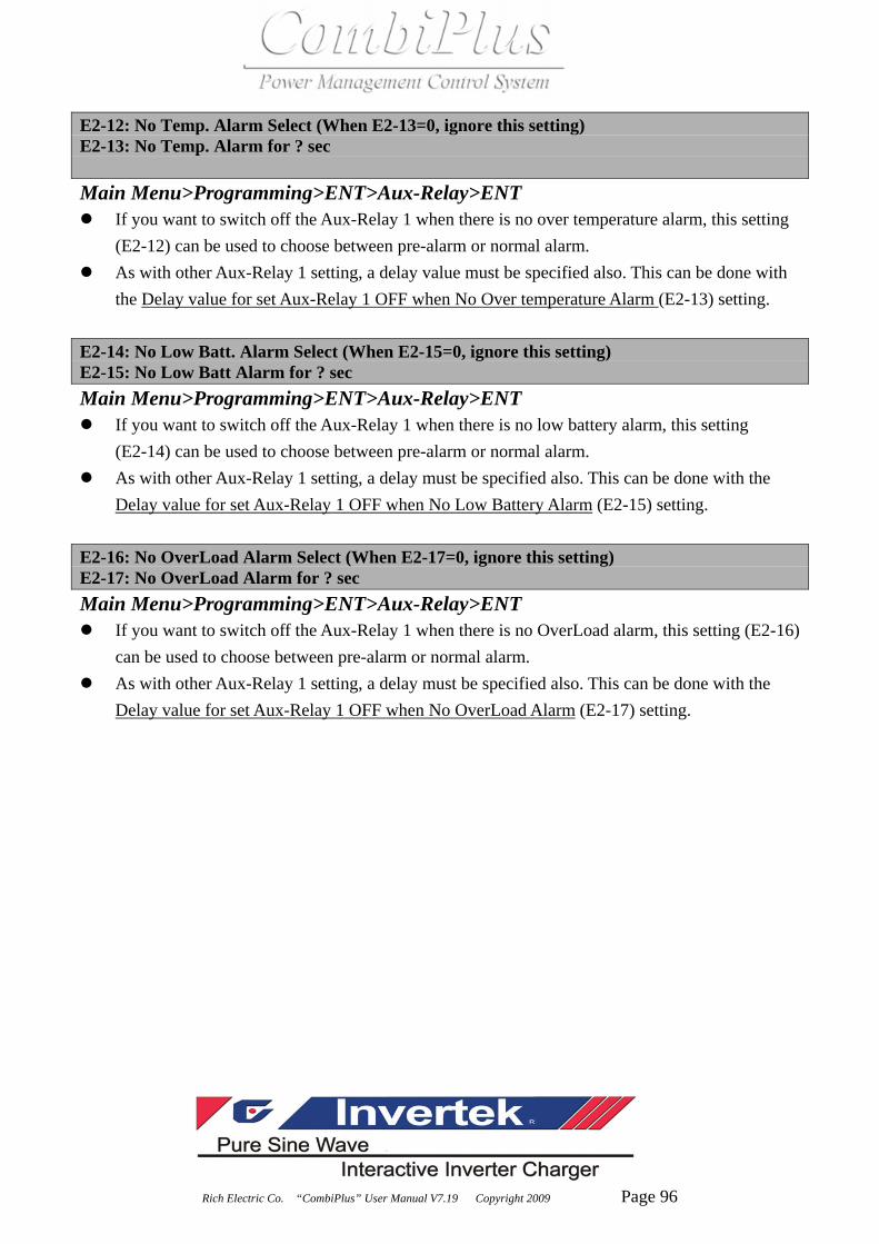
Rich Electric Co. “CombiPlus” User Manual V7.19 Copyright 2009 Page 96
E2-12: No Temp. Alarm Select (When E2-13=0, ignore this setting) E2-13: No Temp. Alarm for ? sec Main Menu>Programming>ENT>Aux-Relay>ENT
If you want to switch off the Aux-Relay 1 when there is no over temperature alarm, this setting (E2-12) can be used to choose between pre-alarm or normal alarm.
As with other Aux-Relay 1 setting, a delay value must be specified also. This can be done with the Delay value for set Aux-Relay 1 OFF when No Over temperature Alarm (E2-13) setting.
E2-14: No Low Batt. Alarm Select (When E2-15=0, ignore this setting) E2-15: No Low Batt Alarm for ? sec Main Menu>Programming>ENT>Aux-Relay>ENT
If you want to switch off the Aux-Relay 1 when there is no low battery alarm, this setting (E2-14) can be used to choose between pre-alarm or normal alarm.
As with other Aux-Relay 1 setting, a delay must be specified also. This can be done with the Delay value for set Aux-Relay 1 OFF when No Low Battery Alarm (E2-15) setting.
E2-16: No OverLoad Alarm Select (When E2-17=0, ignore this setting) E2-17: No OverLoad Alarm for ? sec Main Menu>Programming>ENT>Aux-Relay>ENT
If you want to switch off the Aux-Relay 1 when there is no OverLoad alarm, this setting (E2-16) can be used to choose between pre-alarm or normal alarm.
As with other Aux-Relay 1 setting, a delay must be specified also. This can be done with the Delay value for set Aux-Relay 1 OFF when No OverLoad Alarm (E2-17) setting.

Rich Electric Co. “CombiPlus” User Manual V7.19 Copyright 2009 Page 97
E2-18: No Udc Ripple Alarm Select (When E2-19=0, ignore this setting) E2-19: No Udc Ripple Alarm for ? sec Main Menu>Programming>ENT>Aux-Relay>ENT
If you want to switch off the Aux-Relay 1 when there is no battery voltage ripple alarm, this setting (E2-18) can be used to choose between pre-alarm or normal alarm.
As with other Aux-Relay 1 setting, a delay must be specified also. This can be done with the Delay value for set Aux-Relay 1 OFF when No Battery voltage Ripple Alarm (E2-19) setting.
E3 Group (Setting Aux-Relay 2 ON Condition) E4 Group (Setting Aux-Relay 2 OFF Condition) E5 Group (Setting Aux-Relay 3 ON Condition) E6 Group (Setting Aux-Relay 3 OFF Condition) ※ Note: The functions and the settings of E3, E4, E5 and E6 Groups are exactly the
same as those of E1 and E2 Group so please refer to above E1 and E2 Group description and setting for E3, E4, E5 and E6 Groups.

Rich Electric Co. “CombiPlus” User Manual V7.19 Copyright 2009 Page 98
E7 Group (Aux-Relay 1 Option) E7-01: Aux-Relay 1 Usage Select Main Menu>Programming>ENT>Aux-Relay>ENT
Setting Function E7-01=0
(Initial setting) Auxiliary Relay 1 is not allowed to be active (Idle).
E7-01=1 Auxiliary Relay 1 is allowed to be active. E7-02: Aux-Relay 1 Invert Select Main Menu>Programming>ENT>Aux-Relay>ENT
Setting Function E7-02=0
(Initial setting) Auxiliary Relay 1 is normal.
E7-02=1 Auxiliary Relay 1 is Invert switch and that is ON becomes off and OFF becomes ON.
This is used to invert the Aux-Relay 1 So ON becomes OFF and OFF becomes ON. In the
program, the labels are adapted to reflect this inversion. E7-03: Aux1 not Switch Off Time (Aux-Relay 1 does not switch off with certain period) Main Menu>Programming>ENT>Aux-Relay>ENT
Use constant E7-03 to determine the minimum ON time. The Aux-Relay 1 will not be switched off within the time specified here measured from the
moment that all on condition are inactive. ※ Note: OFF conditions with a delay of 0 minute, ignore this setting. E8 Group (Aux-Relay 2 Option) E9 Group (Aux-Relay 3 Option) ※ The functions and the settings of E8 and E9 Groups are exactly the same as those
of E7 Group so please refer to above E7 Group description and setting for E8 and E9 Groups.

Rich Electric Co. “CombiPlus” User Manual V7.19 Copyright 2009 Page 99
Chapter 7 User Constants 4.2 The following is the operation flow
MENU
*** Main Menu ***
Operation
*** Main Menu ***
Initialize
*** Main Menu ***
Programming
*** Main Menu ***
Modified Constants
*** Main Menu ***
Operation
MENU GROUP Function Parameters Parameter Edit
*** Main Menu ***
Operation
*** Main Menu ***
Initialize
*** Main Menu *** Group B Function B1 Output Frequency B1-01=0 ***
Programming General Output Frequency 50Hz 50Hz
MENU GROUP Function Parameters Parameter Edit
*** Main Menu *** Group B Function B1 Output Frequency B1-01=0 ***
Programming General Output Frequency 50Hz 50Hz
Main Menu
DSPL
DSPL
DSPL
DSPL
Quick Return Main Menu-Operation
DSPL
DSPLENTER
DSPL
ENTER
DSPL
ENTER
DSPL
ENTER
DSPL
MODE 1MODE 1 MODE 1MODE
Quick Return Main Menu-Progeamming
ENTER
DSPL
ENTER
DSPL
ENTER
DSPL
ENTER
DSPL
MODE 2MODE 2 MODE MODE 2

Rich Electric Co. “CombiPlus” User Manual V7.19 Copyright 2009 Page 100
MENU Function PARAMETERS
*** Main Menu *** Function U1 AC IN Voltage Control Mode Solar Charger Status
Operation Monitor U1-01 = 220V U1-08 = Mode1 U1-15 = xxx
AC IN Current Operation Status Solar Supply Current
U1-02 = 00.0A U1-09 = xxxxxxxxU1-16 = 0.0A
AC OUT Voltage Aux-Relay Status Solar Supply Power
U1-03 = 230V U1-10 = xxx U1-17 = 0.0W
AC OUT Current Elapsed Time Solar : Amp-Hours
U1-04 = 00.0A U1-11 = 0HR U1-18 = 0AH
Battery Voltage Bat. Temp. SensorSolar:TotalAmp-Hours
U1-05 = 24.0V U1-12=--℃ U1-19 = 0AH
Battery RippleVoltag CPU ID 1 AC IN Voltage
U1-06 = 0.0V U1-13 = CPD0706U1-01 = 220V
Battery Current CPU ID 2
U1-07 = 0A U1-14 = CPM0701
Function U2
Fault Trace
Function U3
Fault History
Function U1
Monitor
MENU GROUP Parameters Parameter Edit Enter
*** Main Menu ***
Operation
*** Main Menu *** Access Level A1-01 = 1 ***
Initialize Constant Set Constant Set Entry Accepted
A1-01 = 0
Operation Only
Select Language A1-02 = 0 ***
English English Entry Accepted
Init Parameters A1-03 = 0 ***
No Initialize No Initialize Entry Accepted
A1-03 = 1
Default Setting
Password 1 Password 1
A1-04 = 0 00"0" Entry Accepted
Access Level Password 1
Constant Set 00"1"
ENTER
DSPL
ENTER
DSPL
Main Menu : Operation
DSPL
Main Menu : Initialize
ENTER
DSPL
ENTER
DSPL
ENTER
DSPL
ENTER
ENTER
ENTER
DSPL
ENTER
ENTER
DSPL
ENTER

Rich Electric Co. “CombiPlus” User Manual V7.19 Copyright 2009 Page 101
MENU GROUP Function Parameters Parameter Edit
*** Main Menu ***
Operation
*** Main Menu ***
Initialize
*** Main Menu *** Group B Function B1 Output Frequency B1-01 = 0 ***
Programming General Output Frequency 50Hz 50Hz Entry Accepted
Group C Function B2 B1-01 = 1
Inverter Auto Transfer Switch 60Hz
Group D Function B3
Charger Parallel System
Group E Function B4
Aux-Relay 2-3 Phase
Group F Function B1
Solar Charger Output Frequency
Group O
Operator
Group B
General
Main Menu : Programing -Function B1 -B1-01
DSPL
DSPLENTER
DSPL
ENTER
DSPL
ENTER
DSPL
ENTER
DSPL
ENTER

Rich Electric Co. “CombiPlus” User Manual V7.19 Copyright 2009 Page 102
MENU GROUP Function Parameters Parameter Edit
*** Main Menu ***
Operation
*** Main Menu ***
Initialize
*** Main Menu *** Group B Function B1
Programming General Output Frequency
Group C Function B2 AC IN Low DisconnectAC IN Low Disconnect
Inverter Auto Transfer SwitchB2-01 = 180V 18"0"V Entry Accepted
Group D Function B3 AC IN Low connect AC IN Low Disconnect
Charger Parallel System B2-02 = 187V 18"1"V
Group E Function B4 AC IN High Connect
Aux-Relay 2-3 Phase B2-03 = 265V
AC IN Low Disconnect
1"8"1V
Group F Function B1 AC IN High Disconnect
Solar Charger Output Frequency B2-04 = 270V
Group O AC IN Current LimitAC IN Low Disconnect
Operator B2-05 = 16A 1"81V
Group B AC IN Waveform Check
General Active
AC IN Low Disconnect
18"1"V
Ground Relay
Connect
AC IN Frequency Range
45Hz~65Hz MODE 3: Udc Lower ? V
B2-14 = 23.5V
AC IN Dynamic Limit
Normal MODE 3: Lower for ? Sec
B2-15 = 0sec
MODE 2: Udc Lower ? V
B2-10 = 23.5V MODE 3: Udc Higher ?V
B2-16 = 28.8V
MODE 2: Lowre for ? Sec
B2-11 = 0sec MODE 3: HigherfFor ?sec
B2-17 = 0sec
MODE 2: Udc Higher ? V
B2-12 = 28.8V AC IN Low Disconnect
B2-01 = 180V
MODE 2: HigherFor ? Sec
B2-13 = 0sec
Main Menu : Programing -Function B2 -B2-01
DSPL
DSPLENTER
DSPL
ENTER
DSPL
ENTER
DSPL
ENTER
DSPL
ENTER
MODE 3
MODE 3
MODE 3
Press or
Key to enable the cursor to go
to the left or the right digit from
the current digit.
MODE 3MODE 4

Rich Electric Co. “CombiPlus” User Manual V7.19 Copyright 2009 Page 103
MENU GROUP Function Parameters Parameter Edit
*** Main Menu ***
Operation
*** Main Menu ***
Initialize
*** Main Menu *** Group B Function B1
Programming General Output Frequency
Group C Function B2
Inverter Auto Transfer Switch
Group D Function B3 Number of Slave Number of Slave
Charger Parallel System B3-01 = 0 "0" Entry Accepted
Group E Function B4 Number of Slave
Aux-Relay 2-3 Phase "1"
Group F Function B1
Solar Charger Output Frequency
Group O
Operator
Group B
General
Main Menu : Programing -Function B3 -B3-01
DSPL
DSPLENTER
DSPL
ENTER
DSPL
ENTER
DSPL
ENTER
DSPL
ENTER
MENU GROUP Function Parameters Parameter Edit
*** Main Menu ***
Operation
*** Main Menu ***
Initialize
*** Main Menu *** Group B Function B1
Programming General Output Frequency
Group C Function B2
Inverter Auto Transfer Switch
Group D Function B3
Charger Parallel System
Group E Function B4 2-3 Phase ConnectionB4-01 = 0 ***
Aux-Relay 2-3 Phase Disable Disable Entry Accepted
Group F Function B1 2-3 Phase Master B4-01 = 1
Solar Charger Output Frequency Slave Enable
Group O 2-3 Phase Type
Operator 3 Phase
Group B
General
Main Menu : Programing -Function B4 -B4-01
DSPL
DSPLENTER
DSPL
ENTER
DSPL
ENTER
DSPL
ENTER
DSPL
ENTER

Rich Electric Co. “CombiPlus” User Manual V7.19 Copyright 2009 Page 104
MENU GROUP Function Parameters Parameter Edit
*** Main Menu ***
Operation
*** Main Menu ***
Initialize
*** Main Menu *** Group B
Programming General
Group C Inverter Out VoltageInverter Out Voltage
Inverter C1-01 = 230V 23"0"V Entry Accepted
Group D DC In Low Shut-downInverter Out Voltage
Charger C1-02 = 18.00V 23"1"V
Group E DC In Low Restart
Aux-Relay C1-03 = 21.80V
Group F Power Assist Select
Solar Charger Enable
Group O Power Assist Level
Operator 2.0
Group B Inverter Out Voltage
General C1-01 = 230V
Main Menu : Programing -Function C1 -C1-01
DSPL
DSPLENTER
DSPL
ENTER
DSPL
ENTER
DSPL
ENTER

Rich Electric Co. “CombiPlus” User Manual V7.19 Copyright 2009 Page 105
MENU GROUP Function Parameters Parameter Edit
*** Main Menu ***
Operation
*** Main Menu ***
Initialize
*** Main Menu *** Group B
Programming General
Group C
Inverter
Group D AC CHARGER SelectionAC CHARGER Selection
Charger Enable Enable Entry Accepted
Group E Charge Curve AC CHARGER Selection
Aux-Relay Adaptive+Safe Disable
Group F Absorption Voltage Float Voltage
Solar Charger D1-03 = 28.80V D1-07 = 27.60V
Group O Rep-Absorption Time Charge Current
Operator D1-04 = 18.00Hr D1-08 = 52A
Group B Rep-Abs Interval Stop After 10Hr Bulk
General D1-05 = 7.00Days Enable
Max. Absorption TimeEqualize Mode Select
D1-06 = 4Hr Enable
AC CHARGER Selection
Enable
Main Menu : Programing -Function D1 -D1-01
DSPL
DSPLENTER
DSPL
ENTER
DSPL
ENTER
DSPL
ENTER
MENU GROUP Function Parameters Parameter Edit
*** Main Menu ***
Operation
*** Main Menu ***
Initialize
*** Main Menu *** Group B
Programming General
Group C
Inverter
Group D
Charger
Group E Function E1 Load Higher than ? ALoad Higher than ? A
Aux-Relay Set Aux1 ON E1-01 = 13.3A 13."3"A Entry Accepted
Group F Function E2 Load Higher than for ?secLoad Higher than ? A
Solar Charger Set Aux1 OFF E1-02 = 0sec 13."4"A
Group O Function E3 Udc Lower than ? V Not Charge for ? Sec
Operator Set Aux2 ON E1-03 = 23.5V E1-07 = 0sec
Group B Function E4 Udc Lower for ?sec Fan ON for ? Sec
General Set Aux2 OFF E1-04 = 0sec E1-08 = 0sec
Function E5 Udc Higher than ? VUdc Ripple Alarm Sel
Set Aux3 ON E1-05 = 32.0V Alarm
Function E6 Udc Higher for ?secUdcRipAlarm for ?sec
Set Aux3 OFF E1-06 = 0sec E1-18 = 0sec
Main Menu : Programing -Group E -Function E1 -E1-01
DSPL
DSPLENTER
DSPL
ENTER
DSPL
ENTER
DSPL
ENTER
DSPL
ENTER

Rich Electric Co. “CombiPlus” User Manual V7.19 Copyright 2009 Page 106
MENU GROUP Function Parameters Parameter Edit
*** Main Menu ***
Operation
*** Main Menu ***
Initialize
*** Main Menu *** Group B
Programming General
Group C
Inverter
Group D
Charger
Group E Function E1 Load Higher than ? ALoad Higher than ? A
Aux-Relay Set Aux-Relay1 ON E2-01 = 3.32A 3.3"2"A Entry Accepted
Group F Function E2 Load Higher than for ?secLoad Higher than ? A
Solar Charger Set Aux-Relay1 OFF E2-02 = 0sec 3.3"3"A
Group O Function E3 Udc Lower than ? V Not Charge for ? Sec
Operator Set Aux-Relay2 ON E2-03 = 23.50V E2-07 = 0sec
Group B Function E4 Udc Lower than for ?secFan ON for ?sec
General Set Aux-Relay2 OFF E2-04 = 0sec E2-08 = 0sec
Function E5 Udc Higher than ? VUdc Ripple Alarm Sel
Set Aux-Relay3 ON E2-05 = 32.00V Alarm
Function E6 Udc Higher than for ?secUdcRipAlarm for ?sec
Set Aux-Relay3 OFF E2-06 = 0sec E2-19 = 0sec
Main Menu : Programing -Group E -Function E2 -E2-01
DSPL
DSPLENTER
DSPL
ENTER
DSPL
ENTER
DSPL
ENTER
DSPL
ENTER

Rich Electric Co. “CombiPlus” User Manual V7.19 Copyright 2009 Page 107
MENU GROUP Function Parameters Parameter Edit
*** Main Menu ***
Operation
*** Main Menu ***
Initialize
*** Main Menu *** Group B
Programming General
Group C Solar Charger EnableF1-01 = 0 ***
Inverter Disable Disable Entry Accepted
Group D Reset Amp-Hours F1-01 = 1
Charger NO Enable
Group E
Aux-Relay
Group F
Solar Charger
Group O
Operator
Group B
General
Main Menu : Programing -Function F1 -F1-01
DSPL
DSPLENTER
DSPL
ENTER
DSPL
ENTER
DSPL
ENTER
MENU GROUP Function Parameters Parameter Edit
*** Main Menu ***
Operation
*** Main Menu ***
Initialize
*** Main Menu *** Group B Function O1 Power-On Monitor Sel O1-01 = 4 ***
Programming General Monitor Select Battery Voltage Battery Voltage Entry Accepted
Group C Function O2 Key Idle Detect TimeO1-01 = 5
Inverter Key Selections O1-02 = 180sec Battery RippleVoltage
Group D Power-On Monitor Sel
Charger Battery Voltage
Group E
Aux-Relay
Group F
Solar Charger
Group O
Operator
Group B
General
Main Menu : Programing -Group O -Function O1 -O1-01
DSPL
DSPLENTER
DSPL
ENTER
DSPL
ENTER
DSPL
ENTER
DSPL
ENTER

Rich Electric Co. “CombiPlus” User Manual V7.19 Copyright 2009 Page 108
MENU GROUP Function Parameters Parameter Edit
*** Main Menu ***
Operation
*** Main Menu ***
Initialize
*** Main Menu *** Group B Function O1
Programming General Monitor Select
Group C Function O2 Key Pressed Beep SelO2-01 = 1 ***
Inverter Key Selections Enable Enable Entry Accepted
Group D Elapsed Time Set O2-01 = 0
Charger O2-02 = 0Hr Disable
Group E Elapsed Time Select
Aux-Relay Power ON
Group F CombiPlus Model Auto Run Select
Solar Charger O2-04 = CP-1500W-242 Auto
Group O MODE Key Hold Time Display Idle Time Set
Operator O2-06 = 5sec O2-09 = 10 Minute
Group B RUNSTOP KeyHoldTime Key Pressed Beep Sel
General O2-07 = 5sec Enable
Main Menu : Programing -Group O -Function O2 -O2-01
DSPL
DSPLENTER
DSPL
ENTER
DSPL
ENTER
DSPL
ENTER
DSPL
ENTER

Rich Electric Co. “CombiPlus” User Manual V7.19 Copyright 2009 Page 109
Chapter 8 Constants list

Rich Electric Co. “CombiPlus” User Manual V7.19 Copyright 2009 Page 110
Menu Group Function Constant LCD Display Range Unit Factory Remark Page
U1-01 AC IN Voltage - 0.1V - 46
U1-02 AC IN Current - 0.1A - 46
U1-03 AC OUT Voltage - 0.1V - 46
U1-04 AC OUT Current - 0.1A - 46
U1-05 Battery Voltage - 0.1V - 46
U1-06 Battery Ripple Volt - 0.1V - 46
U1-07 Battery Current - 0.1A - 46
U1-08 Control Mode - - - 47
U1-09 Operation Status - - - NOTE 1 47
U1-10 Aux-Relay Status - - - NOTE 2 47
U1-11 Elapsed Time - 1hour - 47
U1-12 Bat.Temp.Sensor - 1°C - 47
U1-13 CPU ID 1 - - - 47
U1-14 CPU ID 2 - - - 48
U1-15 Solar Charger Status - - - NOTE 5 48
U1-16 Solar Supply Current - 0.1A - NOTE 5 48
U1-17 Solar Supply Power - 1W - NOTE 5 48
U1-18 Solar Amp-Hours - 0.1AH - NOTE 5 48
U1-19 Solar Total Amp-Hours - 0.1AH - NOTE 5 48
U1 Monitor
U1-35 External ATS Status - - - - 48
U2-01 Current Fault - - - 49
U2-02 Last Fault - - - 49
U2-03 AC IN Voltage - 0.1V - 49
U2-04 AC IN Current - 0.1A - 49
U2-05 AC OUT Voltage - 0.1V - 49
U2-06 AC OUT Current - 0.1A - 50
U2-07 Battery Voltage - 0.1V - 50
U2-08 Battery Ripple Volt - 0.1V - 50
U2-09 Battery Current - 0.1A - 50
U2-10 Control Mode - - - 50
U2-11 Operation Status - - - NOTE 1 50
U2-12 Aux-Relay Status - - - NOTE 2 50
U2-13 Elapsed Time - 1hour - 51
Operation
U
Monitor
U2 Fault Trace
U2-14 Solar Charger Status - - - NOTE 5 51
Menu Group Function Constant LCD Display Range Unit Factory Remark Page

Rich Electric Co. “CombiPlus” User Manual V7.19 Copyright 2009 Page 111
U2-15 Solar Charge Current - 0.1A - NOTE 5 51
U2-16 Solar Supply Power - 1W - NOTE 5 51
U2-17 Solar : Amp-Hours - 1AH - NOTE 5 51
U2-18 Solar:TotalAmp-Hours - 1AH - NOTE 5 51
U2 Fault
Trace
U2-26 Bat.Temp. Sensor - 1°C - 51
U3-01 Last Fault - - - 52
U3-02 Fault Message 2 - - - 52
U3-03 Fault Message 3 - - - 52
U3-04 Fault Message 4 - - - 52
U3-05 Elapsed Time 1 - 1hour - 52
U3-06 Elapsed Time 2 - 1hour - 53
U3-07 Elapsed Time 3 - 1hour - 53
Operation
U
Monitor
U3 Fault
History
U3-08 Elapsed Time 4 - 1hour - 53
A1-01 Access Level 0~1 1 1 0: Operation Only
1: Constant Set 74
A1-02 Select Language - - 0 0:English 75
A1-03 Init Parameters 0~1 1 0 0: No Initialize
1:Default Setting 75
Initialize A Initialize A1 Initialize
A1-04 Password 1 0~999 1 0 76
B1 Output
Frequency B1-01 Output Frequency 0~1 1 0 0: 50 Hz 1:60 Hz 77
B2-01 AC IN Low Disconnect NOTE 3 1V NOTE 3 78
B2-02 AC IN Low Connect NOTE 3 1V NOTE 3 78
B2-03 AC IN High Connect NOTE 3 1V NOTE 3 78
B2-04 AC IN High Disconnect NOTE 3 1V NOTE 3 79
B2-05 AC IN Current Limit NOTE 3 0.1A NOTE 3
79
B2-06 AC IN Waveform Check 0~1 1 1 0: Ignore 1: Active 79
B2-07 Ground Relay 0~1 1 1 0: Disconnect
1: Connect 80
B2-08 ACIN Frequency Range 0~1 1 1 0:50/60Hz+-5Hz
1:45Hz~65Hz 80
Programm-ing B General
B2 Auto
Transfer
Switch
B2-09 AC IN DynaCur Shift 0~1 1 0 0: Normal
1:Dynamic 89

Rich Electric Co. “CombiPlus” User Manual V7.19 Copyright 2009 Page 112
Menu Group Function Constant LCD Display Range Unit Factory Remark Page
B2-10 MODE 4: BatLo?V ATS
ON
0~32.00
0~16.00 0.01V
23.5V
11.75V 82
B2-11 MODE 4: BatLo?S ATS
ON 0~255 1 sec 10 sec 82
B2-12 MODE 4: BatHi?V
ATSOFF
0~32.0
0~16.0 0.01V
28.8V
14.4V 82
B2-13 MODE 4: BatHi?S
ATSOFF 0~255 1 sec 60 sec 82
B2-14 MODE 3: BatLo?V ATS
ON
0~32.0
0~16.0 0.01V
23.5V
11.75V 82
B2-15 MODE 3: BatLo?S ATS
ON 0~255 1 sec 10 sec 82
B2-16 MODE 3: BatHi?V
ATSOFF
0~32.0
0~16.0 0.01V
28.8V
14.4V 82
B2-17 MODE 3: BatHi?S
ATSOFF 0~255 1 sec 60 sec 82
B2-18 MODE1:ACINCurrent Lmt NOTE 3 0.1A NOTE 3 83
B2-19 MODE2:ACINCurrent Lmt NOTE 3 0.1A NOTE 3 83
B2-20 MODE3:ACINCurrent Lmt NOTE 3 0.1A NOTE 3 83
B2-21 MODE4:ACINCurrent Lmt NOTE 3 0.1A NOTE 3 83
B General B2 Auto
Transfer
Switch
B2-29 External ATS Select Disable/ enable - Disable 83
B3 Parallel B3-01 Number of Slave 0~4 1 0 84
B4-01 2-3 Phase Connection 0~1 1 0 0:Disable
1:Enable 84
B4-02 2-3 Phase Master 0~1 1 0 0:Slave
1:Master 85
B4 2-3 Phase
B4-03 2-3 Phase Type 0~2 1 0
0:3 phase
1: Split phase 180
2: Two Leg phase
120
85
C1-01 Inverter Out Voltage NOTE 3 1V NOTE 3 86
C1-02 Bat Low ? V Shut-down NOTE 3 0.01V NOTE 3 86
Programming
C Inverter C1 Inverter
C1-03 Bat Low ? V Restart NOTE 3 0.01V NOTE 3 86

Rich Electric Co. “CombiPlus” User Manual V7.19 Copyright 2009 Page 113
Menu Group Function Constant LCD Display Range Unit Factory Remark Page
C1-04 Auto Power Saving 0~1 1 1 0: Disable
1: Enable 86
C1-05 Power Support Select 0~1 1 1 0: Disable
1: Enable 87
C Inverter C1 Inverter
C1-06 Power Support Level 1.0~3.5 0.1 2.0 87
D1-02 Charge Curve 1~3 1 3
1: Fixed
2: Adaptive
3: Adaptive+safe
89
D1-03 Absorption Voltage NOTE 3 0.01V NOTE 3 90
D1-04 Rep-Absorption Time 1~72 0.25hour 4 4x0.25=1 hour 90
D1-05 Rep-Abs Interval 1~180 0.25day 28 28x0.25=7day 90
D1-06 Max. Absorption Time 1~8 1hour 4hour 90
D1-07 Float Voltage NOTE 3 0.01V NOTE 3 90
D1-08 Charge Current NOTE 3 1A NOTE 3 90
D1-09 Stop After 10Hr Bulk 0~1 1 1 0:Disable
1:Enable 91
D Charger D1 Charger
D1-10 Equalize Mode Select 0~1 1 1 0:Disable
1:Enable 91
E1-01 LOAD Higher than ? A NOTE 3 0.01A NOTE 3 92
E1-02 LOAD Higher for ? sec 0~255 1sec 0sec 92
E1-03 Udc Lower than ? V NOTE 3 0.01V NOTE 3 92
E1-04 Udc Lower for ? sec 0~255 1sec 0sec 92
E1-05 Udc Higher than ? V NOTE 3 0.01V NOTE 3 92
E1-06 Udc Higher for ? sec 0~255 1sec 0sec 92
E1-07 Not Charge for ? sec 0~255 1sec 0sec 92
E1-08 Fan On for ? sec 0~255 1sec 0sec 92
E1-09 When bulk Protection 0~1 1 0 0:Disable
1:Enable 93
E1-10 System Fault Occurs 0~1 1 0 0:Disable
1:Enable 93
E1-11 Temp. Alarm Sel 0~1 1 0 0:Alarm
1:Pre-alarm 93
Programming
E Aux-Relay E1 Set Aux-
Relay 1 ON
E1-12 Temp. Alarm for ?sec 0~255 1sec 0sec 93

Rich Electric Co. “CombiPlus” User Manual V7.19 Copyright 2009 Page 114
Menu Group Function Constant LCD Display Range Unit Factory Remark Page
E1-13 Low Batt. Alarm Sel 0~1 1 0 0:Alarm
1:Pre-alarm 93
E1-14 Low Batt. for ? sec 0~255 1sec 0sec 93
E1-15 Overload Alarm Sel 0~1 1 0 0:Alarm
1:Pre-alarm 93
E1-16 OL Alarm for ? sec 0~255 1sec 0sec 93
E1-17 Udc Ripple Alarm Sel 0~1 1 0 0:Alarm
1:Pre-alarm 94
E Aux-Relay E1 Set Aux-
Relay 1 ON
E1-18 UdcRipAlarm for ? sec 0~255 1sec 0sec 94
E2-01 Load Lower than ? A NOTE 3 0.01A NOTE 3 94
E2-02 Load Lower for ? sec 0~255 1sec 0sec 94
E2-03 Udc Lower than ? V NOTE 3 0.01V NOTE 3 94
E2-04 Udc Lower for ? sec 0~255 1sec 0sec 94
E2-05 Udc Higher than ? V NOTE 3 0.01V NOTE 3 94
E2-06 Udc Higher for ? sec 0~255 1sec 0sec 94
E2-07 Charging for ? sec 0~255 1sec 0sec 95
E2-08 Fan Off for ? sec 0~255 1sec 0sec 95
E2-09 Charge Finished ? Min 0~1000 1min 0 95
E2-10 RY1 not ON for ? mins 0~1000 1min 0 95
E2-11 AC IN Loss for ? sec 0~255 1sec 0sec 95
E2-12 No Temp. Alarm Sel 0~1 1 0 0:Alarm
1:Pre-alarm 96
E2-13 No Temp. Alarm ? sec 0~255 1sec 0sec 96
E2-14 No Low Bat. Alarm Sel 0~1 1 0 0:Alarm
1:Pre-alarm 96
E2-15 No Low Bat for ? sec 0~255 1sec 0sec 96
E2-16 No OL Alarm Sel 0~1 1 0 0:Alarm
1:Pre-alarm 96
E2-17 No OL Alarm for ? sec 0~255 1sec 0sec 96
E2-18 No UdcRipple Alarm Sel 0~1 1 0 0:Alarm
1:Pre-alarm 97
Programm-
ing
E Aux-Relay E2 Set Aux-
Relay 1
OFF
E2-19 No UdcRipple Alarm ?sec 0~255 1sec 0sec 97

Rich Electric Co. “CombiPlus” User Manual V7.19 Copyright 2009 Page 115
Menu Group Function Constant LCD Display Range Unit Factory Remark Page
E3-01 Load Higher than ? A NOTE 3 0.01A NOTE 3 97
E3-02 Load Higher for ?sec 0~255 1sec 0sec 97
E3-03 Udc Lower than ? V NOTE 3 0.01V NOTE 3 97
E3-04 Udc Lower for ? sec 0~255 1sec 0sec 97
E3-05 Udc Higher than ? V NOTE 3 0.01V NOTE 3 97
E3-06 Udc Higher for ? sec 0~255 1sec 0sec 97
E3-07 Not Charge for ? sec 0~255 1sec 0sec 97
E3-08 Fan On for ? sec 0~255 1sec 0sec 97
E3-09 When bulk Protection 0~1 1 0 0:Disable
1:Enable 97
E3-10 System Fault Occurs 0~1 1 0 0:Disable
1:Enable 97
E3-11 Temp. Alarm Sel 0~1 1 0 0:Alarm
1:Pre-alarm 97
E3-12 Temp. Alarm for ?sec 0~255 1sec 0sec 6-19
E3-13 Low Batt. Alarm Sel 0~1 1 0 0:Alarm
1:Pre-alarm 97
E3-14 Low Batt. for ? sec 0~255 1sec 0sec 97
E3-15 Overload Alarm Sel 0~1 1 0 0:Alarm
1:Pre-alarm 97
E3-16 OL Alarm for ? sec 0~255 1sec 0sec 97
E3-17 Udc Ripple Alarm Sel 0~1 1 0 0:Alarm
1:Pre-alarm 97
E3 Set Aux-
Relay 2 ON
E3-18 UdcRipAlarm for ?sec 0~255 1sec 0sec 97
E4-01 Load Lower than ? A NOTE 3 0.01A NOTE 3 97
E4-02 Load Lower for ? sec 0~255 1sec 0sec 97
E4-03 Udc Lower than ? V NOTE 3 0.01V NOTE 3 97
E4-04 Udc Lower for ? sec 0~255 1sec 0sec 97
E4-05 Udc Higher than ? V NOTE 3 0.01V NOTE 3 97
E4-06 Udc Higher for ? sec 0~255 1sec 0sec 97
E4-07 Charging for ? sec 0~255 1sec 0sec 97
E4-08 Fan OFF for ? sec 0~255 1sec 0sec 97
E4-09 Charge Finished ?Min 0~1000 1min 0 97
Programm-
ing
E Aux-Relay
E4 Set Aux-
Relay 2
OFF
E4-10 RY2 not ON for ?mins 0~1000 1min 0 97

Rich Electric Co. “CombiPlus” User Manual V7.19 Copyright 2009 Page 116
Menu Group Function Constant LCD Display Range Unit Factory Remark Page
E4-11 AC IN Loss for ?sec 0~255 1sec 0sec 97
E4-12 No Temp. Alarm Sel 0~1 1 0 0:Alarm
1:Pre-alarm 97
E4-13 No Temp. Alarm ? sec 0~255 1sec 0sec 97
E4-14 No Low Bat. Alarm Sel 0~1 1 0 0:Alarm
1:Pre-alarm 97
E4-15 No Low Bat for ? sec 0~255 1sec 0sec 97
E4-16 No OL Alarm Sel 0~1 1 0 0:Alarm
1:Pre-alarm 97
E4-17 No OL Alarm for ? sec 0~255 1sec 0sec 97
E4-18 No UdcRipple Alarm Sel 0~1 1 0 0:Alarm
1:Pre-alarm 97
E4 Set Aux-
Relay 2
OFF
E4-19 No UdcRipple Alarm ?sec 0~255 1sec 0sec 97
E5-01 Load Higher than ? A NOTE 3 0.01A NOTE 3 97
E5-02 Load Higher for ?sec 0~255 1sec 0sec 97
E5-03 Udc Lower than ? V NOTE 3 0.01V NOTE 3 97
E5-04 Udc Lower for ? sec 0~255 1sec 0sec 97
E5-05 Udc Higher than ? V NOTE 3 0.01V NOTE 3 97
E5-06 Udc Higher for ? sec 0~255 1sec 0sec 97
E5-07 Not Charge for ? sec 0~255 1sec 0sec 97
E5-08 Fan ON for ? sec 0~255 1sec 0sec 97
E5-09 When bulk Protection 0~1 1 0 0:Disable
1:Enable 97
E5-10 System Fault Occurs 0~1 1 0 0:Disable
1:Enable 97
E5-11 Temp. Alarm Sel 0~1 1 0 0:Alarm
1:Pre-alarm 97
E5-12 Temp. Alarm for ?sec 0~255 1sec 0sec 97
E5-13 Low Batt. Alarm Sel 0~1 1 0 0:Alarm
1:Pre-alarm 97
E5-14 Low Batt. for ? sec 0~255 1sec 0sec 97
E5-15 Overload Alarm Sel 0~1 1 0 0:Alarm
1:Pre-alarm 97
Programm-
ing
E Aux-Relay
E5 Set Aux-
Relay 3 ON
E5-16 OL Alarm for ? sec 0~255 1sec 0sec 97

Rich Electric Co. “CombiPlus” User Manual V7.19 Copyright 2009 Page 117
Menu Group Function Constant LCD Display Range Unit Factory Remark Page
E5-17 Udc Ripple Alarm Sel 0~1 1 0 0:Alarm
1:Pre-alarm 97
E5 Set Aux-
Relay 3 ON
E5-18 UdcRipAlarm for ?sec 0~255 1sec 0sec 97
E6-01 Load Lower than ? A NOTE 3 0.01A NOTE 3 97
E6-02 Load Lower for ? sec 0~255 1sec 0sec 97
E6-03 Udc Lower than ? V NOTE 3 0.01V NOTE 3 97
E6-04 Udc Lower for ? sec 0~255 1sec 0sec 97
E6-05 Udc Higher than ? V NOTE 3 0.01V NOTE 3 97
E6-06 Udc Higher for ? sec 0~255 1sec 0sec 97
E6-07 Charging for ? sec 0~255 1sec 0sec 97
E6-08 Fan OFF for ? sec 0~255 1sec 0sec 97
E6-09 Charge Finished ?Min 0~1000 1min 0 97
E6-10 RY3 not ON for ?mins 0~1000 1min 0 97
E6-11 AC IN Loss for ?sec 0~255 1sec 0sec 97
E6-12 No Temp. Alarm Sel 0~1 1 0
0:Alarm
1:Pre-alarm
97
E6-13 No Temp. Alarm ? sec 0~255 1sec 0sec 97
E6-14 No Low Bat. Alarm Sel 0~1 1 0 0:Alarm
1:Pre-alarm 97
E6-15 No Low Bat for ? sec 0~255 1sec 0sec 97
E6-16 No OL Alarm Sel 0~1 1 0 0:Alarm
1:Pre-alarm 97
E6-17 No OL Alarm for ? sec 0~255 1sec 0sec 97
E6-18 No UdcRipple Alarm Sel 0~1 1 0 0:Alarm
1:Pre-alarm 97
E6
Set Aux-
Relay 3
OFF
E6-19 No UdcRipple
Alarm ?sec 0~255 1sec 0sec
97
E7-01 Aux1 Usage Select 0~1 1 0 0:Do not use Aux
1: Use Aux 98
E7-02 Aux1 Invert Select 0~1 1 0 0: Normal
1: Invert switch 98
Programm-
ing
E Aux-Relay
E7 Aux-
Relay 1
Option
E7-03 Aux1 notSwitchOff T 0~1000 1 min 0 98

Rich Electric Co. “CombiPlus” User Manual V7.19 Copyright 2009 Page 118
Menu Group Function Constant LCD Display Range Unit Factory Remark Page
E8-01 Aux2 Usage Select 0~1 1 0 0:Do not use Aux
1: Use Aux 98
E8-02 Aux2 Invert Select 0~1 1 0 0: Normal
1: Invert switch 98
E8 Aux-
Relay 2
Option
E8-03 Aux2 notSwitchOff T 0~1000 1 min 0 98
E9-01 Aux3 Usage Select 0~1 1 0 0:Do not use Aux
1: Use Aux 98
E9-02 Aux3 Invert Select 0~1 1 0 0: Normal
1: Invert switch 98
E Aux-Relay
E9 Aux-
Relay 3
Option
E9-03 Aux3 notSwitchOff T 0~1000 1 min 0 98
F1-01 Solar Charger Enable 0~1 1 1
0: Disable
1: Enable
NOTE 5
-
F1-02 Reset Amp-Hours 0~1 1 0
0: No
1: Yes
NOTE 5
-
F Solar Charger F1 Solar
Charger
F1-03 Solar Monitor Sel 0~10 1 0
0: Sum of display
1~10: independent
display
NOTE 5
-
O1-01 Power-ON Monitor Sel 0~18 1 4 NOTE 4 43 O1 Monitor
Select O1-02 Key Idle Detect Time 10~600 1sec 180 sec 43
O2-01 Key Pressed Beep Sel 0~1 1 1 0:Disable
1:Enable 44
O2-02 Elapsed Time Reset 0~60000 1hour 0 44
O2-03 Elapsed Time Select 0~1 1 0 0:Power ON
1: Run Time 44
O2-04 CombiPlus® Model - - - 44
O2-06 MODE Key Hold Time 2~10 1sec 5 sec 44
O2-07 RUN/STOP KeyHoldTime 2~10 1sec 2 sec 45
O2-08 Auto Run Select 0~1 1 1 0: Manual
1: Auto 45
Programm-
ing
O Operator
O2 Key
Selections
O2-09 Display IdleTime Set 0~60 1min 10 min 45

Rich Electric Co. “CombiPlus” User Manual V7.19 Copyright 2009 Page 119
NOTE 1: Operation Status U1-09 = X X X X X X X X X X X X
Fault:
0=OK
1=Fault Udc ripple:
0=OK
1=Udc-ripple
Pre-alarm
OL:
0=OK
1=Over load pre-alarm
Battery Low:
0=OK
1=Battery low pre-alarm
Remoter:
0=Remoter disconnect
1=Remoter connect
AC OUT:
0=No output
1=output
AC IN:
0=AC IN disconnect
1=AC IN connect
OH:
0=OK
1=OH Pre-alarm
ATS:
0=OFF
1=ON
AC CHARGER:
0=OFF
1=ON
Inverter:
0=OFF
1=ON
RUN/STOP:
0=STOP
1=RUN
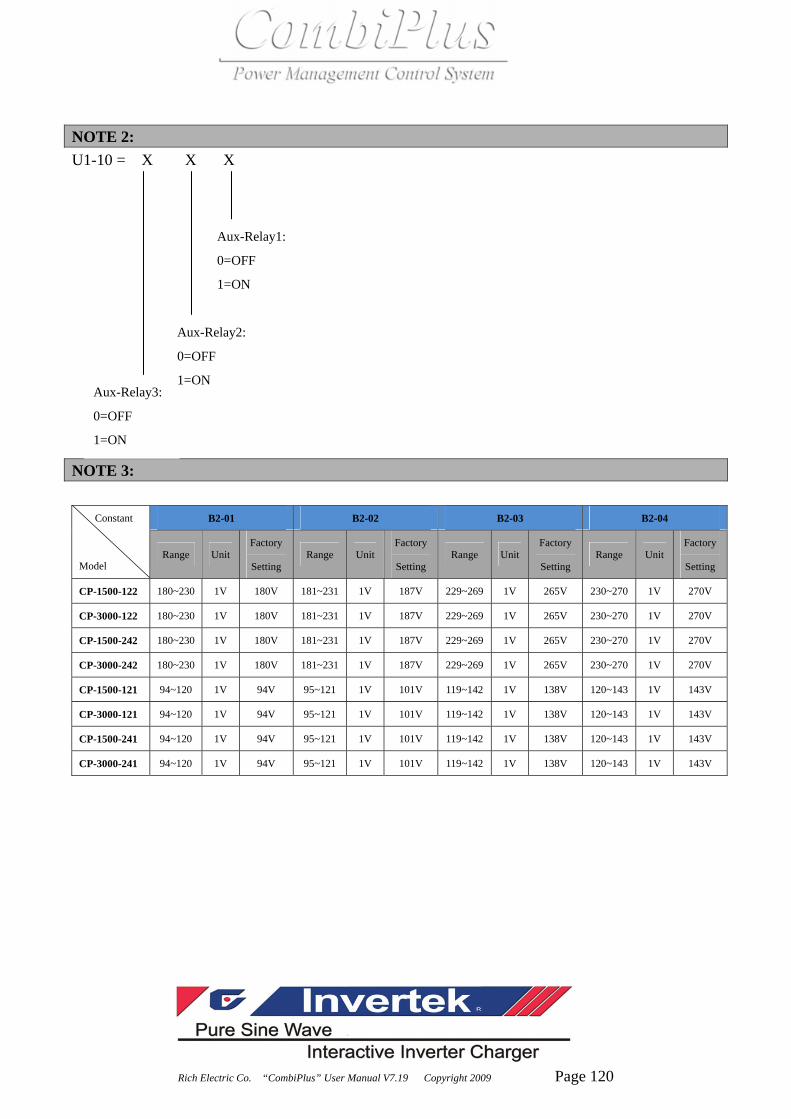
Rich Electric Co. “CombiPlus” User Manual V7.19 Copyright 2009 Page 120
NOTE 2: U1-10 = X X X
NOTE 3:
B2-01 B2-02 B2-03 B2-04 Constant
Model Range Unit
Factory
Setting Range Unit
Factory
Setting Range Unit
Factory
Setting Range Unit
Factory
Setting
CP-1500-122 180~230 1V 180V 181~231 1V 187V 229~269 1V 265V 230~270 1V 270V
CP-3000-122 180~230 1V 180V 181~231 1V 187V 229~269 1V 265V 230~270 1V 270V
CP-1500-242 180~230 1V 180V 181~231 1V 187V 229~269 1V 265V 230~270 1V 270V
CP-3000-242 180~230 1V 180V 181~231 1V 187V 229~269 1V 265V 230~270 1V 270V
CP-1500-121 94~120 1V 94V 95~121 1V 101V 119~142 1V 138V 120~143 1V 143V
CP-3000-121 94~120 1V 94V 95~121 1V 101V 119~142 1V 138V 120~143 1V 143V
CP-1500-241 94~120 1V 94V 95~121 1V 101V 119~142 1V 138V 120~143 1V 143V
CP-3000-241 94~120 1V 94V 95~121 1V 101V 119~142 1V 138V 120~143 1V 143V
Aux-Relay3:
0=OFF
1=ON
Aux-Relay2:
0=OFF
1=ON
Aux-Relay1:
0=OFF
1=ON

Rich Electric Co. “CombiPlus” User Manual V7.19 Copyright 2009 Page 121
B2-05 C1-01 C1-02 C1-03 Constant
Model Range Unit
Factory
Setting Range Unit
Factory
SettingRange Unit
Factory
Setting Range Unit
Factory
Setting
CP-1500-122 1.0~16.0 0.1A 16.0A 210~245 1V 230V 9.3~13.0 0.01V 9.3V 10.9~17.0 0.01V 10.9V
CP-3000-122 2.0~32.0 0.1A 32.0A 210~245 1V 230V 9.3~13.0 0.01V 9.3V 10.9~17.0 0.01V 10.9V
CP-1500-242 1.0~16.0 0.1A 16.0A 210~245 1V 230V 18.6~26.0 0.01V 18.6V 21.8~34.0 0.01V 21.8V
CP-3000-242 2.0~32.0 0.1A 32.0A 210~245 1V 230V 18.6~23.0 0.01V 18.6V 21.8~34.0 0.01V 21.8V
CP-1500-121 2.0~30.0 0.1A 30.0A 94~128 1V 120V 9.3~13.0 0.01V 9.3V 10.9~17.0 0.01V 10.9V
CP-3000-121 4.0~60.0 0.1A 60.0A 94~128 1V 120V 9.3~13.0 0.01V 9.3V 10.9~17.0 0.01V 10.9V
CP-1500-241 2.0~30.0 0.1A 30.0A 94~128 1V 120V 18.6~26.0 0.01V 18.6V 21.8~34.0 0.01V 21.8V
CP-3000-241 4.0~60.0 0.1A 60.0A 94~128 1V 120V 18.6~23.0 0.01V 18.6V 21.8~34.0 0.01V 21.8V
D1-03 D1-07 D1-08 E1-01,E3-01,E5-01 Constant
Model Range Unit
Factory
Setting Range Unit
Factory
Setting Range Unit
Factory
Setting Range Unit
Factory
Setting
CP-1500-122 12.0~16.0 0.01V 14.40V 12.0~16.0 0.01V 13.80V 0~70 1A 35A 0~29.3 0.01A 6.65A
CP-3000-122 12.0~16.0 0.01V 14.40V 12.0~16.0 0.01V 13.80V 0~140 1A 70A 0~58.6 0.01A 13.30A
CP-1500-242 24.0~32.0 0.01V 28.80V 24.0~32.0 0.01V 27.60V 0~35 1A 17A 0~29.3 0.01A 6.65A
CP-3000-242 24.0~32.0 0.01V 28.80V 24.0~32.0 0.01V 27.60V 0~70 1A 35A 0~58.6 0.01A 13.30A
CP-1500-121 12.0~16.0 0.01V 14.40V 12.0~16.0 0.01V 13.80V 0~70 1A 35A 0~44.7 0.01A 12.75A
CP-3000-121 12.0~16.0 0.01V 14.40V 12.0~16.0 0.01V 13.80V 0~140 1A 70A 0~113.0 0.01A 25.5A
CP-1500-241 24.0~32.0 0.01V 28.80V 24.0~32.0 0.01V 27.60V 0~35 1A 17A 0~44.7 0.01A 12.75A
CP-3000-241 24.0~32.0 0.01V 28.80V 24.0~32.0 0.01V 27.60V 0~70 1A 35A 0~113.0 0.01A 25.5A
E1-03,E3-03,E5-03 E1-05,E3-05,E5-05 E2-01,E4-01,E6-01 E2-03,E4-03,E6-03 Constant
Model Range Unit
Factory
Setting Range Unit
Factory
Setting Range Unit
Factory
Setting Range Unit
Factory
Setting
CP-1500-122 0~17.5 0.01V 11.75V 0~17.5 0.01V 16.0V 0~29.3 0.01A 1.66A 0~17.5 0.01V 11.75V
CP-3000-122 0~17.5 0.01V 11.75V 0~17.5 0.01V 16.0V 0~42.6 0.01A 3.32A 0~17.5 0.01V 11.75V
CP-1500-242 0~35.0 0.01V 23.5V 0~35.0 0.01V 32.0V 0~29.3 0.01A 1.66A 0~35.0 0.01V 23.5V
CP-3000-242 0~35.0 0.01V 23.5V 0~35.0 0.01V 32.0V 0~42.6 0.01A 3.32A 0~35.0 0.01V 23.5V
CP-1500-121 0~17.5 0.01V 11.75V 0~17.5 0.01V 16.0V 0~44.75 0.01A 3.18A 0~17.5 0.01V 11.75V
CP-3000-121 0~17.5 0.01V 11.75V 0~17.5 0.01V 16.0V 0~83.0 0.01A 6.37A 0~17.5 0.01V 11.75V
CP-1500-241 0~35.0 0.01V 23.5V 0~35.0 0.01V 32.0V 0~44.75 0.01A 3.18A 0~35.0 0.01V 23.5V
CP-3000-241 0~35.0 0.01V 23.5V 0~35.0 0.01V 32.0V 0~83.0 0.01A 6.37A 0~35.0 0.01V 23.5V
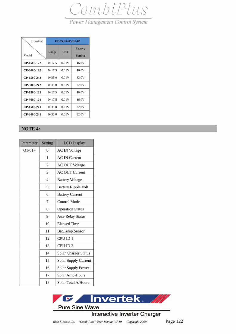
Rich Electric Co. “CombiPlus” User Manual V7.19 Copyright 2009 Page 122
E2-05,E4-05,E6-05 Constant
Model Range Unit
Factory
Setting
CP-1500-122 0~17.5 0.01V 16.0V
CP-3000-122 0~17.5 0.01V 16.0V
CP-1500-242 0~35.0 0.01V 32.0V
CP-3000-242 0~35.0 0.01V 32.0V
CP-1500-121 0~17.5 0.01V 16.0V
CP-3000-121 0~17.5 0.01V 16.0V
CP-1500-241 0~35.0 0.01V 32.0V
CP-3000-241 0~35.0 0.01V 32.0V
NOTE 4: Parameter Setting LCD Display
0 AC IN Voltage
1 AC IN Current
2 AC OUT Voltage
3 AC OUT Current
4 Battery Voltage
5 Battery Ripple Volt
6 Battery Current
7 Control Mode
8 Operation Status
9 Aux-Relay Status
10 Elapsed Time
11 Bat.Temp.Sensor
12 CPU ID 1
13 CPU ID 2
14 Solar Charger Status
15 Solar Supply Current
16 Solar Supply Power
17 Solar Amp-Hours
O1-01=
18 Solar Total A/Hours

Rich Electric Co. “CombiPlus” User Manual V7.19 Copyright 2009 Page 123
NOTE 5: The constants marked with NOTE 5 are only visible when extension port (Port C) is connected. After power on, the CombiPlus® will start to scan each built-in module and extension module. The constants marked with NOTE 5 will be visible only when the extension port (Port C) is connected with extension module. A1-04=Password 1 Lock the constants setting (A1-01=1) 6. Finish setting all the programmable parameters to desired values. 7. Change A1-01=0 (Operation only), factory setting is A1-01=1 (Constants set). 8. Go to A1-04 and press RUN/STOP key and UP key at the same time till A1-05 parameter occurs. 9. Enter the desired password (max. 4 digits) 10. Press UP key to leave A1-05
Above procedure completes locking the constants setting and no more programming selection would appear. A1-01 would only display 0 (Operation only) and would not display 1 (Constants set).
Unlock the constants setting 3. Enter the password in A1-04 to be exactly the same as the one earlier set in A1-05 4. When the password in A1-04 matches the one earlier set in A1-05, the unlocking is completed.
A1-01=1 (Constants set) would appear again for programming.

Rich Electric Co. “CombiPlus” User Manual V7.19 Copyright 2009 Page 124
Chapter 9 Trouble Shooting
Proceed as follows for a quick detection of common faults. DC loads must be disconnected from the batteries and the AC loads must be disconnected from
the INVERTER before the INVERTER and/or battery charger (AC CHARGER) is tested. Consult your Rich Electric dealer if the fault cannot be resolved. Problem/Error message Possible Cause Solution
The “CombiPlus®” fails to operate when power on.
The battery voltage is too high or too low.
Ensure that the battery voltage is within the correct value range.
‘ ’: blink
The battery voltage is low. Charge the battery or check the battery connections.
The “CombiPlus®” cuts out because the battery voltage is too low.
Charge the battery or check the battery connections.
‘ ’: blink
The load on the inverter of “CombiPlus®” is higher than the normal load.
Reduce the load.
“CombiPlus®” cuts out due to excessive load. Or “CombiPlus®” has been Over Loaded and caused Internal Damage.
Reduce the load. If Overload warning does not reset after restart the “CombiPlus®” will need to be sent to service for repair.
‘ ’: blink
The ambient temperature is too high, or the load is excessive.
Place the “CombiPlus®” in a cool and well-ventilated room, or reduce the load.
‘Udc-UV’ Battery under volt
Udc-UV Battery under volt
‘OL’ Inverter OverLoad
OL Inverter OverLoad
‘OH’ Heatsink Max Temp.

Rich Electric Co. “CombiPlus” User Manual V7.19 Copyright 2009 Page 125
The ambient temperature is too high, or the load is excessive.
Place the “CombiPlus®” in a cool and well-ventilated room, or reduce the load.
‘ ’: blink
Voltage ripple on the DC input exceeds 1.25Vrms
Check the battery cables and terminals. Check the battery capacity; increase it if necessary.
The INVERTER of “CombiPlus®” cuts out as a result of excessive voltage ripple on the DC input
Install batteries with a higher capacity. Use shorter and/or thicker battery cables and reset the CombiPlus® (Power OFF and ON again).
‘ ’: blink
Battery charger is not in normal charging status to cause battery voltage too high. Incorrect battery voltage connection (12V system but connected to 24V battery)
“CombiPlus®” will need to be sent to service for repair. Recheck if the CombiPlus® and the battery voltage is matched.
‘ ’: blink
The actual charge current is 1.5 times larger than the set current value (D1-08) when AC CHARGER is operating.
Stop the Charge mode of the “CombiPlus®”. “CombiPlus®” will need to be sent to service for repair.
OH Heatsink Max Temp.
‘Udc-ripple’ Volt Ripple Exceeds
Udc-ripple Volt Ripple Exceeds
‘Udc-OV’ Battery over voltage.
Udc-OV Battery over voltage.
‘Idc-OC’ Over current.
Idc-OC Over current.

Rich Electric Co. “CombiPlus” User Manual V7.19 Copyright 2009 Page 126
‘ ’: blink
The charging time of AC CHARGER has been over 10 hours and remains in Bulk Charge mode. (D1-09=1) shows the battery is at fault.
Replace the battery banks.
The AC IN voltage or frequency is out of range.
Ensure that the AC IN voltage is within the range 220V system: 180VAC~260VAC 110V system: 90VAC~130VAC And that the frequency matches the setting.
The charger is not functioning
“CombiPlus®” internal circuit breaker has tripped.
Reset the internal circuit breaker.
Incorrect charging current. Set the charging current at between (0.1~0.2)× battery capacity.
A defective battery connection.
Check the battery terminals.
The absorption voltage has been set to an incorrect value.
Adjust the absorption voltage to the correct value.
The float voltage has been set to an incorrect value.
Adjust the float voltage to the correct value.
The battery is not being charged fully.
The internal DC fuse is defective
“CombiPlus®” will need to be set to service for repair.
‘Bat-NG’ Battery Fault
Bat-NG Battery Fault

Rich Electric Co. “CombiPlus” User Manual V7.19 Copyright 2009 Page 127
The absorption voltage has been set to an incorrect value.
Adjust the absorption voltage to the correct value.
The battery is overcharged. The float voltage has been set to an incorrect value.
Adjust the float voltage to the correct value.
The battery is too small. Reduce the charging current or use a battery with a higher capacity.
A defective battery. Replace the battery. The battery is overcharged.
The battery is too hot. Connect a Battery Temperature Sensor (BTS-3)
Battery over temperature (> 50℃)
1. Allow battery to cool Down. 2. Place battery in a cool Environment. 3. Check for shorted cells.
Battery charge current drop to 0 A when the absorption voltage is reached.
Battery Temperature Sensor (BTS-3) is faulty
1. Unplug Battery Temperature Sensor (BTS-3) from “CombiPlus®” and power off the “CombiPlus®” then wait 5 seconds and Power on again. 2. If the “CombiPlus®” AC
CHARGE normally, the BTS-3 is faulty and
needs to be replaced.

Rich Electric Co. “CombiPlus” User Manual V7.19 Copyright 2009 Page 128
NOTES: