© siemens ag 2009. all rights reserved. industry sectorpage 1 “how to use sinasave” (status:...
TRANSCRIPT
© Siemens AG 2009. All rights reserved.
Industry SectorPage 1
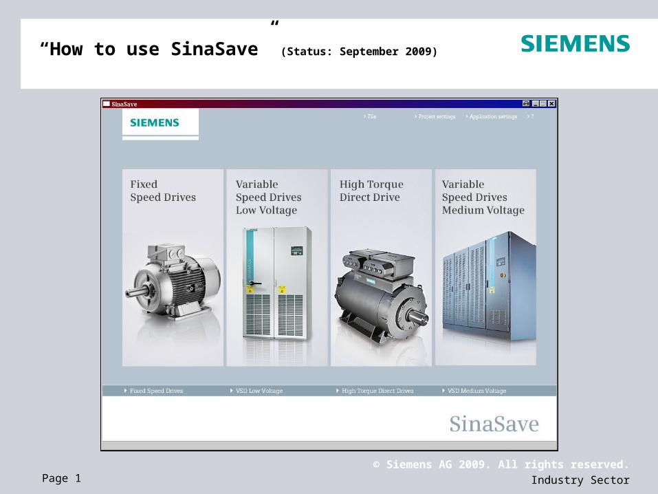
“How to use SinaSave” (Status: September 2009)

© Siemens AG 2009. All rights reserved.
Industry SectorPage 2
SinaSave® 4.0Products
SinaSave 3.0 SinaSave 4.0
VSD
(low voltage)
Micromaster 430 / 440 Micromaster 430 / 440
SINAMICS G150 SINAMICS G150
--- SINAMICS G110 / G120 /G130 (NEW)
VSD
(medium voltage)
--- Robicon Perfect Harmony (NEW)
--- SINAMICS GM150 (NEW)
HTDD --- HT-direct – air-cooled - (690V) (NEW)
FSDIEC motors IEC motors
NEMA motors NEMA motors
© Siemens AG 2009. All rights reserved.
Industry SectorPage 3
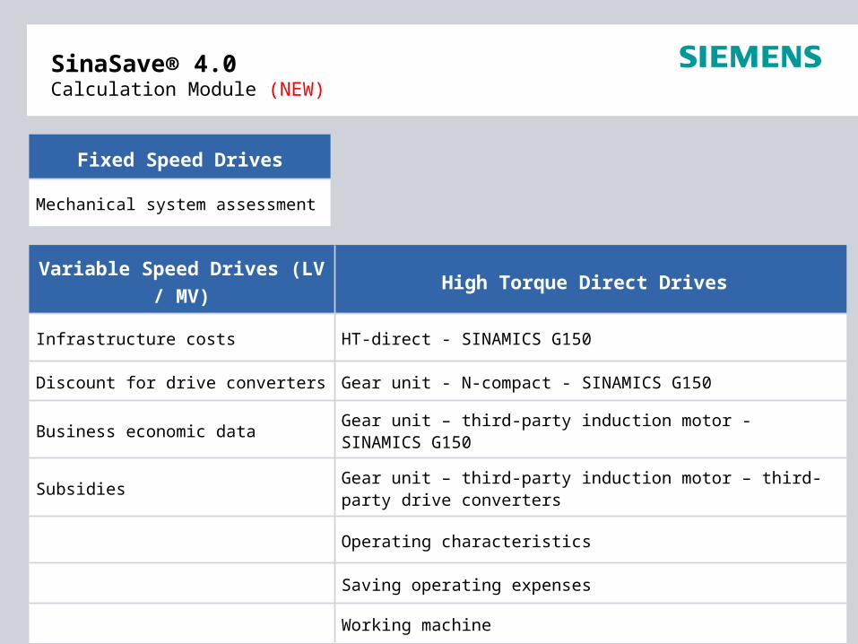
SinaSave® 4.0 Calculation Module (NEW)
Variable Speed Drives (LV / MV) High Torque Direct Drives
Infrastructure costs HT-direct - SINAMICS G150
Discount for drive converters Gear unit - N-compact - SINAMICS G150
Business economic data Gear unit – third-party induction motor - SINAMICS G150
SubsidiesGear unit – third-party induction motor – third-party drive converters
Operating characteristics
Saving operating expenses
Working machine
Fixed Speed Drives
Mechanical system assessment

© Siemens AG 2009. All rights reserved.
Industry SectorPage 4
SinaSave® 4.0 Functions (NEW)
Automatic update function
Resetting input values
Mechanical system assessment for 4-pole motors (Fixed Speed Drives)
Conversion – metric into the Anglo-American system of dimensions
Resetting input values
Central screen form to select the language, currency, pressure units / flow units and project data
Dynamic exchange rate update through EZB
Export to Microsoft Office
Optimized lifecycle cost calculation (VSD)

© Siemens AG 2009. All rights reserved.
Industry SectorPage 5
SinaSave® 4.0 User-friendliness
SinaSave 3.0 SinaSave 4.0
The information area for the help relating to the input and output fields is centrally arranged
The help for the particular input and output field is associated with the specific input and output field
When entering data, a check is not made for errors
When entering data, a check is made for errors
Result sheet Improved output structure of the result sheet

© Siemens AG 2009. All rights reserved.
Industry SectorPage 6
SinaSave® 4.0Download from the Internet - Part I
www.siemens.com/energysaving (general information about energy saving)
Link to SinaSave: www.siemens.com/sinasave
Click here and register
Fill in the form and submit
© Siemens AG 2009. All rights reserved.
Industry SectorPage 7
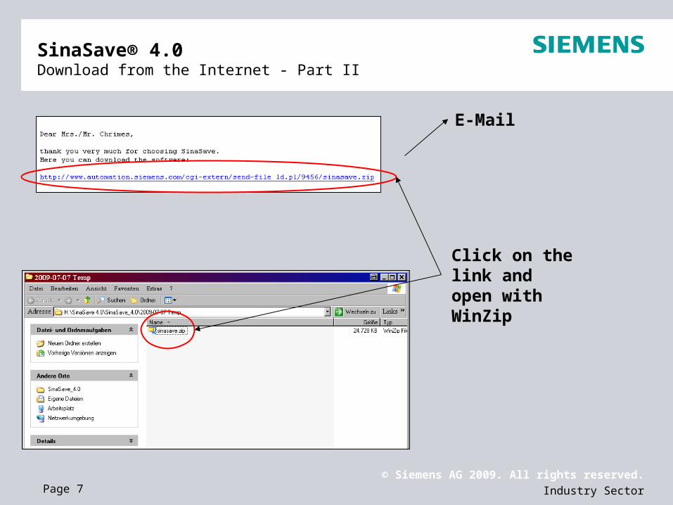
SinaSave® 4.0 Download from the Internet - Part II
Click on the link and open with WinZip
© Siemens AG 2009. All rights reserved.
Industry SectorPage 8
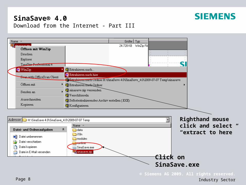
SinaSave® 4.0Download from the Internet - Part III
Righthand mouse click and select “extract to here”
Click on SinaSave.exe

© Siemens AG 2009. All rights reserved.
Industry SectorPage 9
SinaSave® 4.0 Start / update
Current version
NEW: Automatic update function runs when connecting with the internet (it involves, e.g. product prices)

© Siemens AG 2009. All rights reserved.
Industry SectorPage 10
SinaSave® 4.0 Project management
Set-up a new project, open and save

© Siemens AG 2009. All rights reserved.
Industry SectorPage 11
SinaSave® 4.0 Project settings
The following entries are possible :
Sales partner Customer data Project description
© Siemens AG 2009. All rights reserved.
Industry SectorPage 12
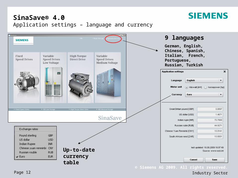
SinaSave® 4.0 Application settings – language and currency
9 languagesGerman, English, Chinese, Spanish, Italian, French, Portuguese,Russian, Turkish
Up-to-date currency table

© Siemens AG 2009. All rights reserved.
Industry SectorPage 13
SinaSave® 4.0 Additional functions
Export to (Project) setting Reset of the entered data Save Print
Conversion from the metric into the Anglo-American system of dimensions
Settings

© Siemens AG 2009. All rights reserved.
Industry SectorPage 14
Enter the motor power rating, pole number, frame material, motor load, operating hours, discount, price, quantity of motors (when calculating a plant or system with several motors)
Mechanical components (4-pole motors only) (NEW)
Fixed Speed DrivesBasic entries - (IEC energy-saving motors) - EFF1 to EFF2
© Siemens AG 2009. All rights reserved.
Industry SectorPage 15
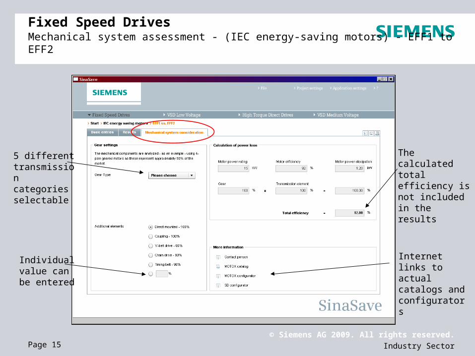
Fixed Speed Drives Mechanical system assessment - (IEC energy-saving motors) - EFF1 to EFF2
Internet links to actual catalogs and configurators
The calculated total efficiency is not included in the results
5 different transmission categories selectable
Individual value can be entered

© Siemens AG 2009. All rights reserved.
Industry SectorPage 16
Fixed Speed DrivesResults - (IEC energy-saving motors) - EFF1 to EFF2
Numerical analysis:
Analysis of the entered data: payback time, saving in kW and saving in € p.a.
Graphic analysis:
Visual analysis of the payback time with two graphs.
Breakeven point - it’s your cash from this
point onwards
© Siemens AG 2009. All rights reserved.
Industry SectorPage 17
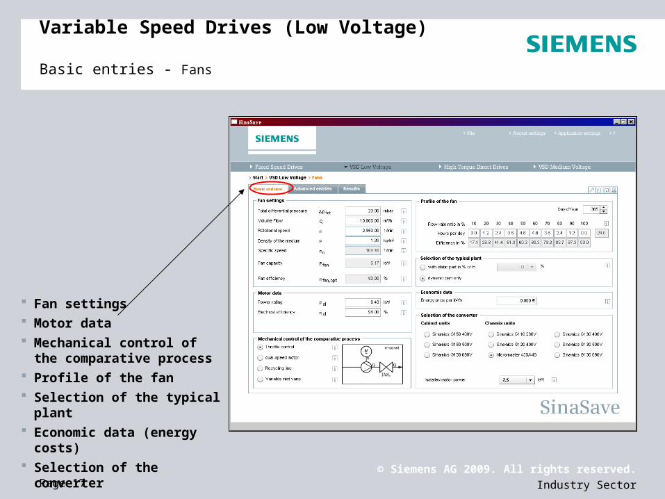
Variable Speed Drives (Low Voltage) Basic entries - Fans
Fan settings Motor data Mechanical control of the
comparative process Profile of the fan Selection of the typical plant Economic data (energy costs) Selection of the converter
© Siemens AG 2009. All rights reserved.
Industry SectorPage 18
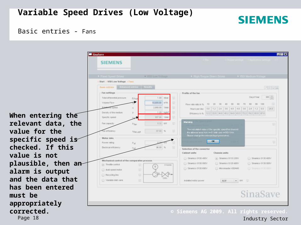
Variable Speed Drives (Low Voltage) Basic entries - Fans
When entering the relevant data, the value for the specific speed is checked. If this value is not plausible, then an alarm is output and the data that has been entered must be appropriately corrected.

© Siemens AG 2009. All rights reserved.
Industry SectorPage 19
Costs for infrastructure Discount Funding/subsidies Additional cost saving
Variable Speed Drives (Low Voltage) Advanced entries - Fans

© Siemens AG 2009. All rights reserved.
Industry SectorPage 20
Variable Speed Drives (Low Voltage) Results - Fans
Results:
Graphic analysis of the entered data
Numerical analysis of the entered data
Energy-saving
potential

© Siemens AG 2009. All rights reserved.
Industry SectorPage 21
Hinweisfeld
Variable Speed Drives (Medium Voltage) Entries - Pumps
Fan settings Motor data Mechanical control of the
comparative process Profile of the fan Selection of the typical plant Economic data (energy costs) Selection of the converter

© Siemens AG 2009. All rights reserved.
Industry SectorPage 22
Variable Speed Drives (Medium Voltage)Advanced entries - Pumps
Costs for infrastructure Discount Funding/subsidies Additional cost savings

© Siemens AG 2009. All rights reserved.
Industry SectorPage 23
Variable Speed Drives (Medium Voltage)Results - Pumps
Results:
Graphic analysis of the entered data
Numerical analysis of the entered data
Potential
for energy saving
© Siemens AG 2009. All rights reserved.
Industry SectorPage 24
High Torque Direct DrivesBackground
The “High Torque Direct Drive“ module determines potential savings relating to
Energy consumption and
Operational cost
using a High Torque Direct Drive instead of a conventional drive system with gearbox and induction motor.
HTDD also calculates
Investment costs and
Payback time

© Siemens AG 2009. All rights reserved.
Industry SectorPage 25
High Torque Direct DrivesComparison settings
The “High Torque Direct Drive” module of SinaSave 4.0 contains three different comparison settings.
A drive system comprising an HT direct drive fed from a SINAMICS G150 low-voltage converter is always compared to a conventional drive system existing of gearbox – induction motor – converter.
There, users can compare the system HT-direct – SINAMICS G150 with a drive system comprising user-defined products a system comprising a user-defined-motor and Siemens converter - or a system comprising Siemens motor and Siemens converter.
The HTDD module takes into consideration air cooled systems and a 690V power supply voltage.

© Siemens AG 2009. All rights reserved.
Industry SectorPage 26
High Torque Direct Drives Entries
The “Basic entries” tab is divided into three areas:
Left: The driven load (driven machine) is defined here
Center: The components of the drive system using an HT-direct motor are defined here
Right: The components of a conventional drive system using gearbox and induction motor are defined here

© Siemens AG 2009. All rights reserved.
Industry SectorPage 27
High Torque Direct Drives Entries - defining the load
The first step is to define the load.
For this purpose, a driven load with a constant load torque is used as basis. This means that the selected torque is available over the complete speed setting range (minimum speed up to maximum speed).
All comparison scenarios use this step in the same way.

© Siemens AG 2009. All rights reserved.
Industry SectorPage 28
High Torque Direct Drives Entries - defining the HT-direct drive system
After defining the load, the components of the HT-direct drive system are automatically selected by SinaSave and the associated technical data and customer prices are displayed in the associated fields.
Due to the fact that SinaSave applies an efficiency derating according to the degree of converter utilization (I/IR) it is possible that the SINAMICS G150 efficiency – which is displayed - differs from the value listed in the catalog.
All of the prices that are shown are estimated customer prices. The values in this field can be exceeded - which allows the user to adapt to the individual situation.
The “Savings basis” is a cost advantage and will be subtracted from the “Total investment”.
The value in this data field can be exceeded.

© Siemens AG 2009. All rights reserved.
Industry SectorPage 29
High Torque Direct DrivesEntries - defining a drive system comprising gearbox and induction motor
The differences between the three comparative scenarios is again shown in this area.
However, the basic configuration – with coupling – gear unit – coupling – motor – drive converter is however the same for all of the scenarios. The differences lie in the motor and drive converter components.
For the scenario “N-compact – Siemens drive converter”, after defining the drive train, all of the fields are automatically filled. The prices are pre-assigned analog to the systemology applied for the HT-direct drive train.
This scenario allows users to either select a 4-, 6- or 8-pole force-ventilated Siemens induction motor. The gear unit ratio is automatically adapted the same as the values of the drive converter.
The efficiencies of motor and converter are adjusted to the degree of utilization.

© Siemens AG 2009. All rights reserved.
Industry SectorPage 30
High Torque Direct Drives Entries - defining a drive system comprising gearbox and induction motor
Also for the scenario “user-defined motor – Siemens converter”, after defining the drive train, the data blocks for the gear unit and drive converter are filled. The fields for the motor data should only be considered as a space retainer. The catalog values of a matching induction motor must be entered into these fields.
The gear unit and converter data are automatically adapted.
The prices are pre-assigned according to the schematic already described.
The efficiencies of the motor and converter are adapted to the degree of utilization. This is the reason why the value of “system efficiency” is not the product of the individual efficiencies that are displayed.
The efficiency of motor is reduced based on the catalog value according to the degree of utilization.

© Siemens AG 2009. All rights reserved.
Industry SectorPage 31
High Torque Direct Drives Entries - defining a drive system comprising gearbox and induction motor
The default values shown in the data blocks of the motor and gear unit should initially be considered as space retainer in the scenario “user-defined motor – user-defined converter”. The catalog values of a suitable motor and drive converter must be entered into these data blocks.
In this case, as well, the value “system efficiency” is not the product of the individual efficiencies that are shown.
The efficiency of the motor and converter were reduced based on the catalog value according to the degree of utilization.

© Siemens AG 2009. All rights reserved.
Industry SectorPage 32
High Torque Direct Drives Entries - defining a drive system comprising gearbox and induction motor
If a motor or drive converter that is under-dimensioned is entered, then a popup window indicates the required minimum power rating or the required minimum rated current.
© Siemens AG 2009. All rights reserved.
Industry SectorPage 33
High Torque Direct Drives Advanced entries
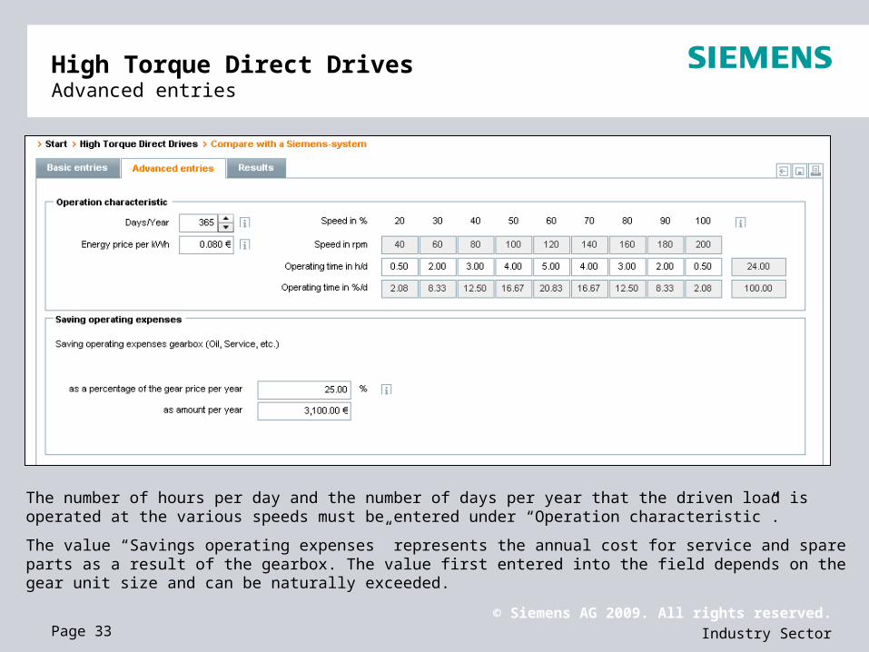
The number of hours per day and the number of days per year that the driven load is operated at the various speeds must be entered under “Operation characteristic”.
The value “Savings operating expenses” represents the annual cost for service and spare parts as a result of the gearbox. The value first entered into the field depends on the gear unit size and can be naturally exceeded.

© Siemens AG 2009. All rights reserved.
Industry SectorPage 34
High Torque Direct Drives Results
The “results“ tab contains a graphic representation of the breakeven point as well as numerical listing of the system differences regarding efficiency, cost of investment and energy costs.
This is followed by the data of the systems for which the values have been calculated under the “Entries” and “Advanced entries” tabs.

© Siemens AG 2009. All rights reserved.
Industry SectorPage 35
Exercise 1:
Exercise- Fixed Speed Drives -
How long is the payback time (in hours) for an EFF1 motor in comparison to an EFF2 motor with the following technical data?
15 kW
Pole number 4
Material: Aluminum
Motor load 4/4
Shift 4000 hours
Energy costs 0,12 €/kWh
Customer discount 50%

© Siemens AG 2009. All rights reserved.
Industry SectorPage 36
Exercise- Fixed Speed Drives -
Results:
© Siemens AG 2009. All rights reserved.
Industry SectorPage 37
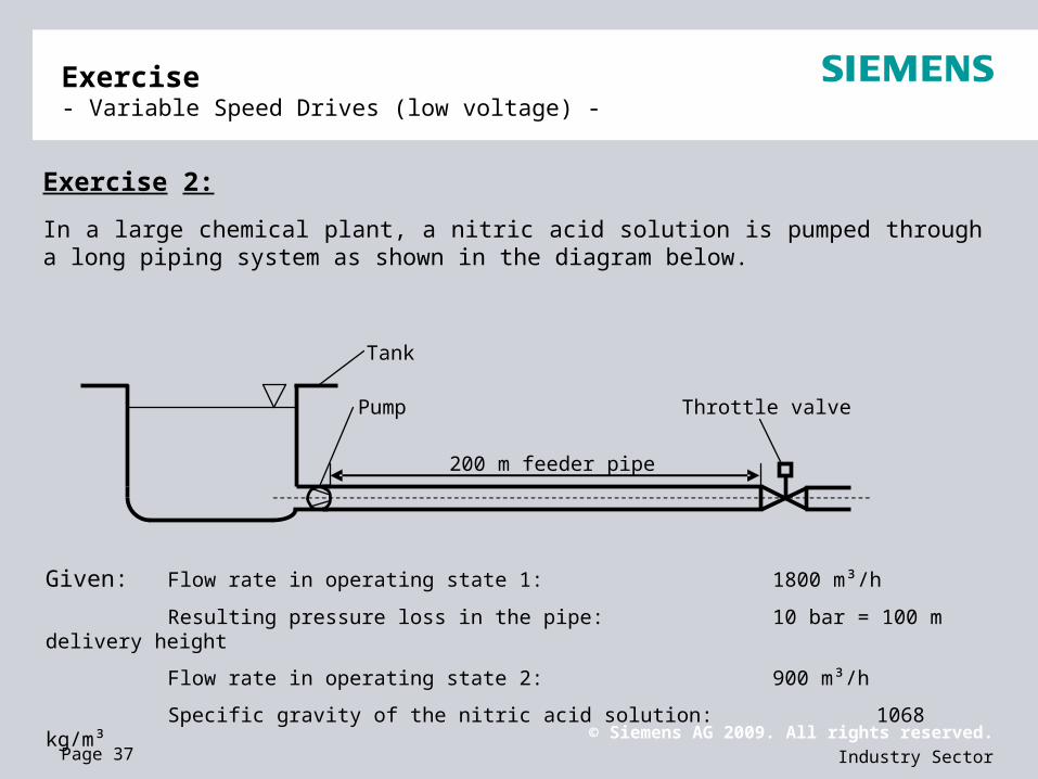
In a large chemical plant, a nitric acid solution is pumped through a long piping system as shown in the diagram below.
Exercise 2:
Exercise - Variable Speed Drives (low voltage) -
Given: Flow rate in operating state 1: 1800 m³/h
Resulting pressure loss in the pipe: 10 bar = 100 m delivery height
Flow rate in operating state 2: 900 m³/h
Specific gravity of the nitric acid solution: 1068 kg/m³
Pump
Tank
200 m feeder pipe
Throttle valve

© Siemens AG 2009. All rights reserved.
Industry SectorPage 38
The plant essentially comprises a tank to which a 200 m long horizontal steel pipe is connected – as well as a pump and a throttle, which are installed in the pipe. The pump has been dimensioned so that it operates at its optimum at operating point 1. Operating point 2 corresponds to a 50% pumping rate and this is adjusted using a throttle valve. The pump is operated 12 hours/per day at operating point 1 – and 12 hours/per day at operating point 2. Using Sinasave, the energy saving that can be expected when using a frequency converter is now calculated.
The following values are obtained for the base settings (refer to the diagram):
Flow rate and delivery height of the pumps at the optimum operating point (1800 m³/h / 100 m)
Specific gravity of the fluid/liquid being pumped (1068 kg/m³)
Operating hours per operating point per day (12 h, 100% flow rate, 12 h, 50 % flow rate)
Power costs per kWh (0.08 Euro/kWh)
Discount for the drive converter: (25%)
Exercise 2:
Exercise - Variable Speed Drives (low voltage) -

© Siemens AG 2009. All rights reserved.
Industry SectorPage 39
Exercise - Variable Speed Drives (low voltage) -
Results 2:

© Siemens AG 2009. All rights reserved.
Industry SectorPage 40
Exercise 3:
A factory is supplied with water as shown in the diagram below.
Exercise - Operating type, Variable Speed Drives (medium voltage) -
Given: Flow rate in operating state 1: 1800 m³/h
Resulting pressure loss in the pipe: 10 bar = 100 m delivery height
Flow rate in operating state 2: 900 m3/h
Specific gravity of water: 1000 kg/m³
Discount for the drive converter: 25%
Pump
Tank
200 m feeder pipe
Throttle valve
100 m

© Siemens AG 2009. All rights reserved.
Industry SectorPage 41
Exercise 3:
Exercise - Operating type, Variable Speed Drives (medium voltage) -
The plant essentially comprises a reservoir, to which a 200 m long pipe is connected. This pipe initially runs horizontally and then vertically upwards to the factory. A pump and a throttle valve are installed in the pipe. The pump is dimensioned so that at operating point 1 it operates at its optimum. Operating point 2 corresponds to a 50% flow rate and is adjusted using a throttle valve. The pump is operated 12 h per day at operating point 1 and 12 h/per day at operating point 2. The energy saving is calculated, which can be expected when using a frequency converter in the following.
The following values are obtained for the base settings (refer to the diagram):
Flow rate and delivery height of the pump at the optimum operating point (1800 m³/h / 200 m)
Speed (2950 rpm)
Specific gravity of the medium (1000 kg/m³)
Operating hours per operating point per day (12 h, 100% flow rate, 12 h, 50 % flow rate)
Energy costs per kWh (0.16 Euro/kWh)
Discount for the drive converter: (25%)
Selection of the typical system with a static component of H: 50 %

© Siemens AG 2009. All rights reserved.
Industry SectorPage 42
Exercise - Variable Speed Drives (low voltage) -
Results 3:

© Siemens AG 2009. All rights reserved.
Industry SectorPage 43
Exercise - Variable Speed Drives (low voltage) -
Results 3:
The characteristics graphically show (as difference between the red and blue lines) the different energy demand as a function of the flow rate. It can be clearly seen that the savings increase, the further the flow rate deviates from the optimum (100%).
For the plant being investigated here, the frequency converter payback time is just 10 months and that for an electricity price of 0.16 Euro per kilowatt hour. The higher the price of electricity, the faster the investment costs are paid back and the more profitable operation is with a frequency converter.
© Siemens AG 2009. All rights reserved.
Industry SectorPage 44
Exercise - High Torque Direct Drives - (new plant)
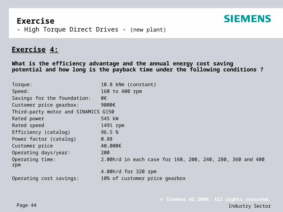
Exercise 4:
What is the efficiency advantage and the annual energy cost saving potential and how long is the payback time under the following conditions ?
Torque: 10.8 kNm (constant)Speed: 160 to 400 rpmSavings for the foundation: 0€Customer price gearbox: 9000€Third-party motor and SINAMICS G150Rated power 545 kWRated speed 1491 rpmEfficiency (catalog) 96.5 %Power factor (catalog) 0.88Customer price 40,000€Operating days/year: 200Operating time: 2.00h/d in each case for 160, 200, 240, 280, 360 and 400 rpm
4.00h/d for 320 rpmOperating cost savings: 10% of customer price gearbox

© Siemens AG 2009. All rights reserved.
Industry SectorPage 45
Exercise - High Torque Direct Drives - (new plant)
Results 4:
Efficiency advantage: 4.5 %
Annual energy cost
saving potential: 16,965 €
Payback-time: 3.88 months

© Siemens AG 2009. All rights reserved.
Industry SectorPage 46
Exercise - High Torque Direct Drives - (plant modernization)
Exercise 5:
How long is the payback time for plant modernization?
Torque: 11.2 kNm (constant)Speed: 180 to 600 rpm
Gear unitSavings for the foundation: 0€Coupling, gearbox- load: 0 €Customer price gearbox: 0 €Coupling, motor-gearbox: 0 €Operating costs per year 2000€Third-party motor Rated power 880 kWRated speed 1489 rpmEfficiency (catalog) 96.5 %Power factor (catalog) 0.86Customer price 0 €Third-party converterRated current 1050 AEfficiency (catalog) 96.8 %Customer price 0 €

© Siemens AG 2009. All rights reserved.
Industry SectorPage 47
Exercise - High Torque Direct Drives - (plant modernization)
Results 5:
Annual energy cost
saving potential: 55,854 €
Payback time: 2.12 years
© Siemens AG 2009. All rights reserved.
Industry SectorPage 48
Links
Downloads:
SinaSave 4.0: http://www.siemens.com/sinasave
Training slide – How to use SinaSave 4.0: http://www.siemens.com/sinasave
Website:
Energy saving: http://www.siemens.com/energysaving
Portfolio Motors and Converters:
Low- voltage-motors: http://www.siemens.com/low-voltage-motors
AC-converters: http://www.automation.siemens.com/_en/portal/html/products/products_ac-converters.htm
AC-motors: http://www.automation.siemens.com/_en/portal/html/products/products_ac-motors.htm