hoshizaki · q-0 september 2005 r-0 december 2005 r-1 november 2006 ... u-0 july 2009 v-0 march...
TRANSCRIPT

Hoshizaki
“A Superior Degreeof Reliability”
www.hoshizaki.com
Models
KM-1300SWH-EKM-1300SAH-E
KM-1300SRH-E
Stackable Crescent Cuber
Hoshizaki America, Inc.
Number: 71217Issued: 4-7-2003Revised: 3-7-2016
PARTS LIST
89/33673/23

2
CONTENTSAuxiliary Codes ...................................................................................................................... 3Note About Ordering Parts .................................................................................................... 3A. Main Assembly & Refrigeration Circuit .............................................................................. 4
KM-1300SAH-E ................................................................................................................. 4KM-1300SWH-E ................................................................................................................ 7KM-1300SRH-E ............................................................................................................... 10
B. Water Circuit .................................................................................................................... 13C. Control Box Assembly ..................................................................................................... 16D. Accessories & Labels ...................................................................................................... 17

3
Auxiliary Codes
KM-1300SAH-E M-0 December 2001M-1 February 2002M-2 August 2002N-0 January 2003N-1 March 2003P-0 December 2003P-1 July 2004 Q-0 March 2005 R-0 February 2006 R-1 June 2006 S-1 January 2007 T-0 January 2008 U-0 January 2009
KM-1300SWH-E P-0 May 2004Q-0 September 2005R-0 December 2005R-1 November 2006 S-1 January 2007 T-0 February 2008 U-0 July 2009 V-0 March 2010
KM-1300SRH-E N-1 April 2003P-0 September 2004 Q-0 October 2005 R-0 May 2006 R-1 November 2006 S-1 February 2007 T-0 February 2008 U-0 January 2009 V-0 January 2010
Auxiliary Code BreakdownThe auxiliary code is the first two characters in the serial number. The first character indicates the year. Years progress or regress in alphabetical order. The series runs from "A" through "V" and the letters "I" and "O" are skipped. The second character indicates significant part changes within a year. Base is "0" and this number advances for each change.
Note About Ordering PartsMost assemblies cannot be ordered as complete units; parts in the assemblies generally must be ordered separately.
IMPORTANTIEC standards require that the clamping means of earthing terminals be adequately secured against accidental loosening and that accessible metal parts of the icemaker which may become live in the event of an insulation fault be permanently and reliably connected to an earthing terminal within the icemaker or to the earthing contact of the icemaker inlet. This is accomplished in this icemaker through the use of stainless steel lock washers.
4
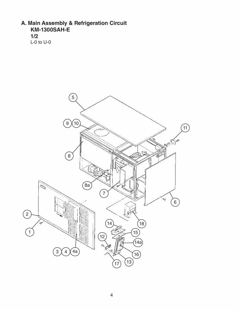
A. Main Assembly & Refrigeration CircuitKM-1300SAH-E1/2L-0 to U-0
1
2
43 4a
5
6
7
8
8a
9 1011
12
13
14
15
17
18
16
14a

5
A. Main Assembly & Refrigeration CircuitKM-1300SAH-E2/2L-0 to U-0
19
20
21 22
23 24
25 26
27 29
28 29
30
32 33
34 34a
35
36
37
38
31
6
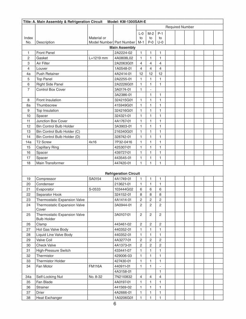
Title: A. Main Assembly & Refrigeration Circuit Model: KM-1300SAH-E
Index No. Description
Material or Model Number Part Number
Required Number
L-0 to
M-1
M-2 to
P-0
P-1 to
U-0
Main Assembly1 Front Panel 2A2224-02 1 1 1
2 Gasket L=1219 mm 4A0808L02 1 1 1
3 Air Filter 2A2063G01 4 4 4
4 Louver 1A0548-01 4 4 4
4a Push Retainer 4A2414-01 12 12 12
5 Top Panel 2A2255-01 1 1 1
6 Right Side Panel 2A2226G01 1 1 1
7 Control Box Cover 3A0174-01 1 -
3A2386-01 1 1
8 Front Insulation 324215G01 1 1 1
8a Thumbscrew 415949G01 1 1 1
9 Top Insulation 324216G01 1 1 1
10 Spacer 324321-01 1 1 1
11 Junction Box Cover 4A1767-01 1 1 1
12 Bin Control Bulb Holder 3A3903-01 1 1 1
13 Bin Control Bulb Holder (C) 216340G01 1 1 1
14 Bin Control Bulb Holder (D) 328742-01 1 1 1
14a T2 Screw 4x16 7P32-0416 1 1 1
15 Capillary Ring 425307-01 1 1 1
16 Spacer 439727-01 1 1 1
17 Spacer 443545-01 1 1 1
18 Main Transformer 447420-01 1 1 1
Refrigeration Circuit19 Compressor SA0154 4A1749-01 1 1 1
20 Condenser 213621-01 1 1 1
21 Evaporator S-0533 103444G02 6 6 6
22 Separator Hook 324152-01 8 8 8
23 Thermostatic Expansion Valve 4A1414-01 2 2 2
24 Thermostatic Expansion Valve Cover
3A0944-01 2 2 2
25 Thermostatic Expansion Valve Bulb Holder
3A0107-01 2 2 2
26 Clamp 443461-02 2 2 2
27 Hot Gas Valve Body 440352-01 1 1 1
28 Liquid Line Valve Body 440352-01 1 1 1
29 Valve Coil 4A3277-01 2 2 2
30 Check Valve 4A1373-01 2 2 2
31 High-Pressure Switch 433441-07 1 1 1
32 Thermistor 429006-03 1 1 1
33 Thermistor Holder 427430-01 1 1 1
34 Fan Motor FM116A 440911-01 1 1 -
4A3158-01 1
34a Self-Locking Nut No. 8-32 7N21I0832 4 4 4
35 Fan Blade 4A0197-01 1 1 1
36 Strainer 441569-02 1 1 1
37 Drier 4A2666-01 1 1 1
38 Heat Exchanger 1A0206G01 1 1 1

7
A. Main Assembly & Refrigeration CircuitKM-1300SWH-E1/2P-0 to V-0
1
3
24
5 6
8a
8
7
9
10
11
12
13
15
16
14
12a
8
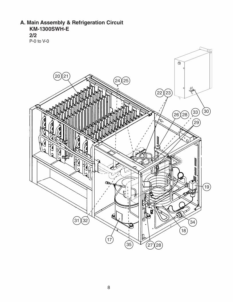
A. Main Assembly & Refrigeration CircuitKM-1300SWH-E2/2P-0 to V-0
17
18
19
20 21
22 23
24 25
26 28
27 28
29
31 32
35
33
34
30
9
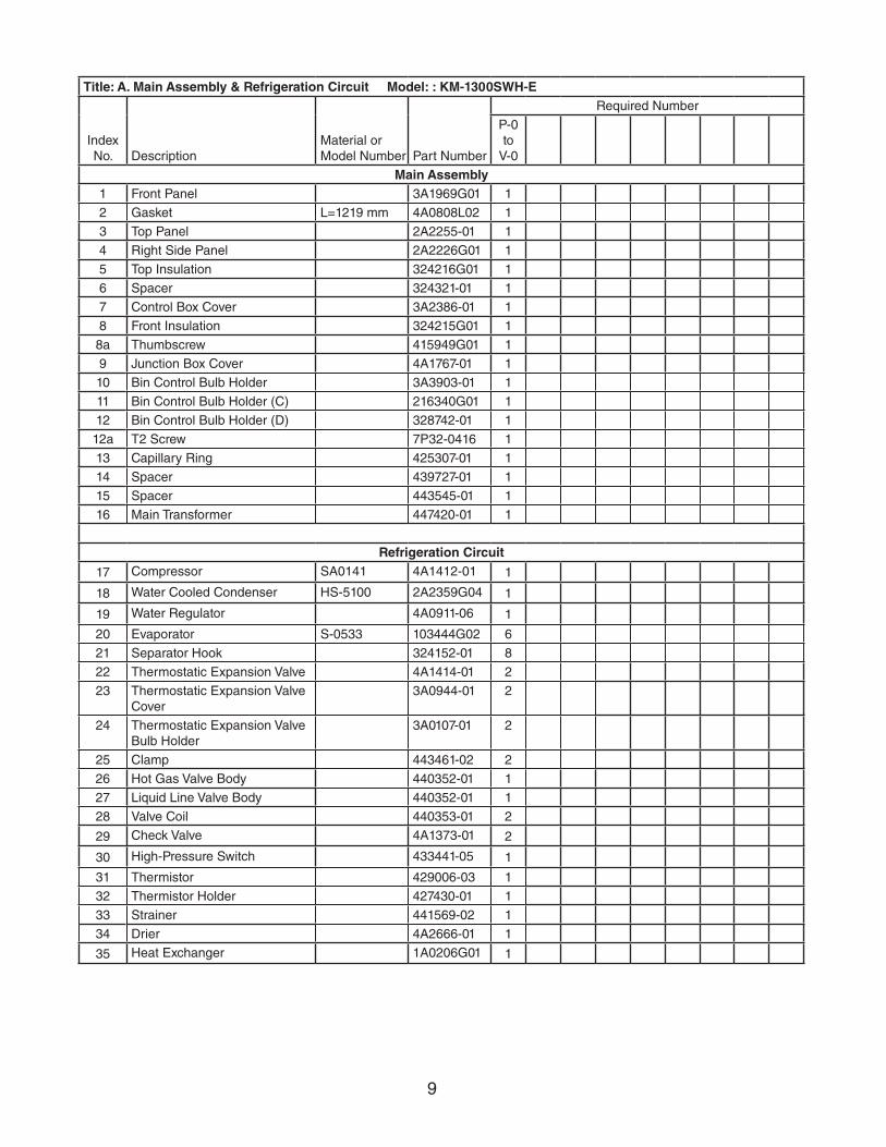
Title: A. Main Assembly & Refrigeration Circuit Model: : KM-1300SWH-E
Index No. Description
Material or Model Number Part Number
Required Number
P-0 to
V-0
Main Assembly1 Front Panel 3A1969G01 1
2 Gasket L=1219 mm 4A0808L02 1
3 Top Panel 2A2255-01 1
4 Right Side Panel 2A2226G01 1
5 Top Insulation 324216G01 1
6 Spacer 324321-01 1
7 Control Box Cover 3A2386-01 1
8 Front Insulation 324215G01 1
8a Thumbscrew 415949G01 1
9 Junction Box Cover 4A1767-01 1
10 Bin Control Bulb Holder 3A3903-01 1
11 Bin Control Bulb Holder (C) 216340G01 1
12 Bin Control Bulb Holder (D) 328742-01 1
12a T2 Screw 7P32-0416 1
13 Capillary Ring 425307-01 1
14 Spacer 439727-01 1
15 Spacer 443545-01 1
16 Main Transformer 447420-01 1
Refrigeration Circuit
17 Compressor SA0141 4A1412-01 1
18 Water Cooled Condenser HS-5100 2A2359G04 1
19 Water Regulator 4A0911-06 1
20 Evaporator S-0533 103444G02 6
21 Separator Hook 324152-01 8
22 Thermostatic Expansion Valve 4A1414-01 2
23 Thermostatic Expansion Valve Cover
3A0944-01 2
24 Thermostatic Expansion Valve Bulb Holder
3A0107-01 2
25 Clamp 443461-02 2
26 Hot Gas Valve Body 440352-01 1
27 Liquid Line Valve Body 440352-01 1
28 Valve Coil 440353-01 2
29 Check Valve 4A1373-01 2
30 High-Pressure Switch 433441-05 1
31 Thermistor 429006-03 1
32 Thermistor Holder 427430-01 1
33 Strainer 441569-02 1
34 Drier 4A2666-01 1
35 Heat Exchanger 1A0206G01 1

10
A. Main Assembly & Refrigeration CircuitKM-1300SRH-E1/2N-1 to V-0
1
2
4a
4
5 6
7
8
9
10
11
12
14
13
15
3
11a

11
A. Main Assembly & Refrigeration CircuitKM-1300SRH-E2/2N-1 to V-0
17
16
18 19
24 26
25 26
20 21
22 23
27
29 30
31
32
33
34
35
28

12
Title: A. Main Assembly & Refrigeration Circuit Model: KM-1300SRH-E
Index No. Description
Material or Model Number Part Number
Required Number
N-1 to
V-0
Main Assembly1 Front Panel 3A1969G01 1
2 Top Panel 2A2255-01 1
3 Right Side Panel 2A2226G01 1
4 Front Insulation 324215G01 1
4a Thumbscrew 415949G01 1
5 Top Insulation 324216G01 1
6 Spacer 324321-01 1
7 Control Box Cover 3A2386-01 1
8 Junction Box Cover 4A1767-01 2
9 Bin Control Bulb Holder 3A3903-01 1
10 Bin Control Bulb Holder (C) 216340G01 1
11 Bin Control Bulb Holder (D) 328742-01 1
11a T2 Screw 7P32-0416 1
12 Capillary Ring 425307-01 1
13 Spacer 439727-01 1
14 Spacer 443545-01 1
15 Main Transformer 447420-01 1
Refrigeration Circuit16 Compressor SA0154 4A1749-02 1
17 Receiver Tank 437652-01 1
18 Evaporator (S-0533) 103444G02 6
19 Separator Hook 324152-01 8
20 Thermostatic Expansion Valve 4A1414-01 2
21 Thermostatic Expansion Valve Cover
3A0944-01 2
22 Thermostatic Expansion Valve Bulb Holder
3A0107-01 2
23 Clamp 443461-02 2
24 Hot Gas Valve Body 440352-01 1
25 Liquid Line Valve Body 440352-01 1
26 Valve Coil 440353-01 2
27 Check Valve 4A1373-01 2
28 High-Pressure Switch 433441-07 1
29 Thermistor 429006-03 1
30 Thermistor Holder 427430-01 1
31 Strainer 441569-02 1
32 Drier 4A2666-01 1
33 Liquid Line Coupling 434136G01 1
34 Discharge Line Coupling 433751G01 1
35 Heat Exchanger 1A0206G01 1

13
B. Water CircuitKM-1300S_H-EL-0 to V-0
10
11
12
13
14
15
16
17
17
18
19
20
20
21
22
23
23
24
25
2627
28
29
31
30
32
3334
3536
37
38
39
40
41
42
43
Pump Motor Assembly
2 3
42a
2b
2c
2d
2e
5
6
7
89
9a
9b
1

14
Title: B. Water Circuit Model: KM-1300S_H-E
Index No. Description
Material or Model Number Part Number
Required Number
L-0 to
V-0
1 Pump Motor Assembly (includes items 2 through 9b)
S-0862 215692A02 1
2 Pump Motor 2U0106-01 1
2a Tooth Washer 7R22-0600 2
2b Hex Head Bolt 7B02-0640 4
2c Flat Washer 7F22-0600 4
2d Split Lock Washer 7L22-0600 4
2e Nut 7N12-0600 4
3 Pump Flange SA0101 215662-01 1
4 Pump Motor Bracket 323904-01 1
5 Mechnical Seal 4A3820-01 1
6 Packing 428547-01 1
7 Impeller 334706G01 1
8 Pin 4A0648-01 1
9 Pump Housing 213687-01 1
9a Hex Head Bolt 7B02-0455 4
9b Flange Nut 7J02-0400 4
10 Water Supply Pipe 4A0768G05 1
11 Rubber Gasket 413854-03 1
12 Inlet Water Valve 4A5251-02 1
13 Distributor Hose (A) 325738-01 1
14 Joint Pipe 439297-01 1
15 Distributor Hose (B) 325738-02 1
16 Spray Tube 437049G01 6
17 Spray Guide (A) 208586-01 18
18 Separator (A) 213622-01 2
19 Separator (B) 2A0100-01 2
20 Cube Guide 214243-01 2
21 Hose (A) 435091-01 1
22 Distributor (Tee) 438276G01 1
23 Distributor Hose (C) 323985-01 2
24 Hose (B) 436599-01 1
25 Drain Valve Housing 323613-01 1
26 Spring 322110-01 1
27 Valve Seat 433705-01 1
28 Overflow Cap 323978-01 1
29 Overflow Joint 323923-02 1
30 Float Switch Connector 426799-04 1
31 Float Switch 4A3624-01 1
32 O-Ring 7611-P018 1
33 O-Ring 7611-G035 1
34 Drain Hose 324757-01 1
35 Drain Plug 309246-01 1
36 O-Ring 7611-P015 1
37 Joint Hose 439296-01 1
38 Distributor (B) 439239-01 1

15
Title: B. Water Circuit Model: KM-1300S_H-E
Index No. Description
Material or Model Number Part Number
Required Number
L-0 to
V-0
39 Flange 439267-02 1
40 Vinyl Hose L=415 mm 7716-2732 1
41 Float Switch Stop 4A0137-01 1
42 Silicone Hose L=140 mm 7730I3812 1
43 Silicone Hose L=390 mm 7730I3896 1
Hose ClampsHose Clamp 25 mm 427443-03 8
Hose Clamp 18 mm 427443-05 1
Hose Clamp 13.5 mm 427443-07 6
Hose Clamp 32 mm 427443-09 2

16
C. Control Box AssemblyKM-1300S_H-EL-0 to V-0
Title: C. Control Box Assembly Model: KM-1300S_H-E
Index No. Description
Material or Model Number Part Number
Required Number
L-0 to
M-1
M-2 to
V-0
1 Start Capacitor 160MFD, 330VAC
4A1094-01 1 1
2 Run Capacitor 35MFD, 440VAC
3A2005-12 1 1
3 Start Relay 4A1107-13 1 1
4 Magnetic Contactor 4A3140-01 1 1
5 Capacitor 15MFD, 250VAC
4A2128-02 1 1
6 Control Transformer 3A0172-01 1 1
7 "E" Control Board 2A1410-01 1 1
7a Control Board Support 4A0336-03 4 4
8 Bin Control Thermostat 4A0824-02 1 -
4A2879-02 1
9 Power Switch 4A2436-01 1 1
10 Fan Motor Capacitor KM-1300SAH-E 5MFD, 250VAC
4A2128-04 1 1
11 Fuse Holder 4A0892-01 1
12 Fuse AGC-10A, 250VAC
4A0893-07 2
1
2
3
4 5
6
7a7
8
9
10
1211

17
D. Accessories & LabelsKM-1300S_H-EL-0 to V-0
1
2
3
Title: D. Accessories & Labels Model: KM-1300S_H-E
Index No. Description
Material or Model Number Part Number
Required Number
L-0to
V-0
1 Hoshizaki Emblem Label 4A0560-01 1
2 Penguin Label 4A0526-01 1
3 Air Filter Label KM-1300SAH-E 426177-01 1
4 Universal Brace 4A0363-01 2
4a Hex Bolt 5×12, SS 7B02-0512 4
5 Thermostat Extension Bracket 3A0408-01 1
6 Thumbscrew 415949G01 1
4a
4
5
6